EP3084755B1 - Antenne omnidirectionnelle compacte pour un sonar trempé - Google Patents
Antenne omnidirectionnelle compacte pour un sonar trempé Download PDFInfo
- Publication number
- EP3084755B1 EP3084755B1 EP14825337.0A EP14825337A EP3084755B1 EP 3084755 B1 EP3084755 B1 EP 3084755B1 EP 14825337 A EP14825337 A EP 14825337A EP 3084755 B1 EP3084755 B1 EP 3084755B1
- Authority
- EP
- European Patent Office
- Prior art keywords
- antenna
- hydrophones
- rings
- longitudinal axis
- sonar
- Prior art date
- Legal status (The legal status is an assumption and is not a legal conclusion. Google has not performed a legal analysis and makes no representation as to the accuracy of the status listed.)
- Active
Links
Images


Classifications
-
- G—PHYSICS
- G01—MEASURING; TESTING
- G01S—RADIO DIRECTION-FINDING; RADIO NAVIGATION; DETERMINING DISTANCE OR VELOCITY BY USE OF RADIO WAVES; LOCATING OR PRESENCE-DETECTING BY USE OF THE REFLECTION OR RERADIATION OF RADIO WAVES; ANALOGOUS ARRANGEMENTS USING OTHER WAVES
- G01S7/00—Details of systems according to groups G01S13/00, G01S15/00, G01S17/00
- G01S7/52—Details of systems according to groups G01S13/00, G01S15/00, G01S17/00 of systems according to group G01S15/00
- G01S7/521—Constructional features
-
- B—PERFORMING OPERATIONS; TRANSPORTING
- B63—SHIPS OR OTHER WATERBORNE VESSELS; RELATED EQUIPMENT
- B63G—OFFENSIVE OR DEFENSIVE ARRANGEMENTS ON VESSELS; MINE-LAYING; MINE-SWEEPING; SUBMARINES; AIRCRAFT CARRIERS
- B63G8/00—Underwater vessels, e.g. submarines; Equipment specially adapted therefor
- B63G8/39—Arrangements of sonic watch equipment, e.g. low-frequency, sonar
-
- G—PHYSICS
- G01—MEASURING; TESTING
- G01S—RADIO DIRECTION-FINDING; RADIO NAVIGATION; DETERMINING DISTANCE OR VELOCITY BY USE OF RADIO WAVES; LOCATING OR PRESENCE-DETECTING BY USE OF THE REFLECTION OR RERADIATION OF RADIO WAVES; ANALOGOUS ARRANGEMENTS USING OTHER WAVES
- G01S15/00—Systems using the reflection or reradiation of acoustic waves, e.g. sonar systems
- G01S15/88—Sonar systems specially adapted for specific applications
-
- G—PHYSICS
- G01—MEASURING; TESTING
- G01S—RADIO DIRECTION-FINDING; RADIO NAVIGATION; DETERMINING DISTANCE OR VELOCITY BY USE OF RADIO WAVES; LOCATING OR PRESENCE-DETECTING BY USE OF THE REFLECTION OR RERADIATION OF RADIO WAVES; ANALOGOUS ARRANGEMENTS USING OTHER WAVES
- G01S7/00—Details of systems according to groups G01S13/00, G01S15/00, G01S17/00
- G01S7/003—Transmission of data between radar, sonar or lidar systems and remote stations
-
- G—PHYSICS
- G10—MUSICAL INSTRUMENTS; ACOUSTICS
- G10K—SOUND-PRODUCING DEVICES; METHODS OR DEVICES FOR PROTECTING AGAINST, OR FOR DAMPING, NOISE OR OTHER ACOUSTIC WAVES IN GENERAL; ACOUSTICS NOT OTHERWISE PROVIDED FOR
- G10K11/00—Methods or devices for transmitting, conducting or directing sound in general; Methods or devices for protecting against, or for damping, noise or other acoustic waves in general
- G10K11/004—Mounting transducers, e.g. provided with mechanical moving or orienting device
- G10K11/006—Transducer mounting in underwater equipment, e.g. sonobuoys
- G10K11/008—Arrays of transducers
-
- G—PHYSICS
- G10—MUSICAL INSTRUMENTS; ACOUSTICS
- G10K—SOUND-PRODUCING DEVICES; METHODS OR DEVICES FOR PROTECTING AGAINST, OR FOR DAMPING, NOISE OR OTHER ACOUSTIC WAVES IN GENERAL; ACOUSTICS NOT OTHERWISE PROVIDED FOR
- G10K11/00—Methods or devices for transmitting, conducting or directing sound in general; Methods or devices for protecting against, or for damping, noise or other acoustic waves in general
- G10K11/18—Methods or devices for transmitting, conducting or directing sound
- G10K11/26—Sound-focusing or directing, e.g. scanning
- G10K11/34—Sound-focusing or directing, e.g. scanning using electrical steering of transducer arrays, e.g. beam steering
-
- G—PHYSICS
- G10—MUSICAL INSTRUMENTS; ACOUSTICS
- G10K—SOUND-PRODUCING DEVICES; METHODS OR DEVICES FOR PROTECTING AGAINST, OR FOR DAMPING, NOISE OR OTHER ACOUSTIC WAVES IN GENERAL; ACOUSTICS NOT OTHERWISE PROVIDED FOR
- G10K2200/00—Details of methods or devices for transmitting, conducting or directing sound in general
- G10K2200/11—Underwater, e.g. transducers for generating acoustic waves underwater
Definitions
- the present invention relates to the general field of sonar detection, particularly implemented in the fight against submarines. It relates more particularly to the field of airborne sonars known as "hardened sonars" used from a helicopter.
- sonars In the context of anti-submarine control activities, in order to be able to detect submarines submerged in a given area, use is generally made of sonars, in particular active sonars. In this context, the deployment of sonars from aerial platforms, airplanes or helicopters is particularly effective because such platforms have great mobility compared to submarines.
- maritime patrol aircraft deploy acoustic buoys, composed of sensors and sometimes acoustic transmitters and a VHF system acting as a communication relay to the aircraft.
- helicopters can also be used to operate sonar transmitters and receivers connected by a cable to their platform, in other words to the helicopter.
- the submerged sub-assembly connected by the cable is called the antenna. It includes the actual sonar transmitters and receivers and possibly electronic equipment associated with the transmitters and receivers. It can also include environmental sensors.
- the launching from the platform, the immersion control as well as the recovery on board of these antennas are carried out by means of a winch located inside the helicopter.
- the winch cable generally carries the sonar signals as well as the electrical energy necessary for acoustic emission and the operation of receivers.
- the helicopter there are equipments necessary for the generation of the acoustic signals and for the processing of the received acoustic data.
- the antenna generally cylindrical to be omnidirectional in bearing and directional in site, is hung by the cable which carries it.
- the largest vertical dimension of the sonar is constrained by the height of the antenna to which the cable hooking must be added to the top of the antenna and at least in part a winch pulley whose diameter depends on the radius of curvature that the cable can withstand. This dimension must be able to fit in height in the helicopter.
- the document US 2004/052160 A1 describes a hull sonar in which a receiving antenna is located around a transmitting antenna.
- the documents FR 2 604 530 A1 and GB 2,093,996 A describe a hardened sonar antenna in which hydrophones are mounted on movable arms.
- the invention aims to reduce the size and the mass of certain subsets of a hardened sonar, in particular the mass and the height of the antenna while maintaining similar acoustic performance.
- the invention also aims to reduce the complexity of certain sub-assemblies, in particular of the antenna. More precisely the invention makes it possible to do without of articulated arms carrying the hydrophones. By avoiding such moving parts, the reliability of the sonar is improved.
- the invention relates to an omnidirectional antenna intended to equip a hardened sonar, according to claim 1.
- the range of a sonar antenna is linked to the working frequency of hydrophones.
- An antenna according to the invention operates at a working frequency of less than 8 kHz.
- the elementary emission rings and the hydrophones operate at a working frequency of less than 8 kHz.
- Nonpilz acoustic components commonly called “Tonpilz” allowing both the emission and the reception of sound waves. For frequencies below 8 kHz, this type of component would be much too bulky and the antenna would be unsuitable for hardened sonar, especially on board a helicopter. To work at low frequency, it is advantageous to distinguish the emission rings from the hydrophones.
- the transmission rings occupy a volume distinct from that of hydrophones.
- volume is meant a space with a convex outline.
- the elementary emission rings and the hydrophones are nested, that is to say, that the volumes occupied by the emission rings and the volume occupied by the hydrophones have common parts.
- the distribution of hydrophones and transmission rings may or may not be regular. The fact of nesting the elementary emission rings and the hydrophone rings makes it possible to distribute the acoustic transmitters and receivers each over a larger volume.
- a first minimum cylindrical volume occupied by the elementary emission rings is defined and a second minimum cylindrical volume occupied by the hydrophones. These two volumes are the smallest possible cylinders including the emission rings or the hydrophones.
- the projections of the hydrophone phase centers in a horizontal plane perpendicular to the longitudinal axis or in a vertical plane containing the longitudinal axis are spaced less than ⁇ / 3, ⁇ being the wavelength at the frequency of job. Reducing the distance between hydrophones in a horizontal plane makes it possible to improve the directivity of the antenna in bearing and between hydrophones in a vertical plane makes it possible to improve the directivity of the antenna in elevation. Depending on the mission for which the antenna is intended, one can choose to favor one or the other of the directivities. It is of course possible to reduce the distance between hydrophones in the two planes.
- the subject of the invention is also a sonar comprising an antenna according to the invention.
- the sonar comprises a computer configured to perform sonar channel formation, parameters of the channel formation being calculated from the covariance of a spatially correlated noise according to a form of robust adaptive processing with respect to errors. antenna calibration.
- the invention is not limited to a sonar fitted to a helicopter.
- the carrier equipped with a hardened sonar according to the invention can be of any kind. By reducing the mass of a hardened sonar, it is for example possible to equip a drone with a sonar according to the invention.
- the figure 1 shows a helicopter 10 hovering over water.
- the helicopter 10 is equipped with an active hardened sonar 11. This type of sonar allows in particular the detection and classification of underwater objects.
- the sonar 11 essentially comprises a winch 12 installed on board the helicopter 10, a cable 13 and an omnidirectional antenna 14, shown immersed on the figure 1 .
- the antenna 14 is suspended from the cable 13 and the winch 12 makes it possible to unwind and wind the cable 13 as a function of the depth at which one wishes to immerse the antenna 14.
- the winch also makes it possible to raise the antenna 14 to the inside the helicopter 10.
- the sonar 11 also includes unrepresented electronic equipment on board the helicopter 10. The equipment makes it possible to operate the sonar, in particular for generating sound waves and for operating waves received echoing the waves emitted. The equipment also makes it possible to supply the antenna 14 with electrical energy.
- the cable 13 performs a dual function, firstly a mechanical support for the antenna 14 and then an electrical connection between the electronic equipment placed on board the helicopter 10 and the antenna 14.
- the electrical connection we include the power supply and the transmission of data to or from antenna 14.
- the antenna 14 then has its own source of electrical energy, for example in the form of a battery.
- Data transmission means for example by radio wave, can be implemented.
- the sonar 11 comprises a computer 15, for example placed at the foot of the winch 12.
- the computer 15 is configured to generate the data transmitted to the antenna 14 and to process the data from the antenna 14.
- the computer 15 is notably configured to perform sonar path training.
- the computer 15 is connected to the cable 13 for example at the through a rotating collector placed on the winch 12.
- the computer 15 is advantageously connected to a screen making it possible to display a sonar image.
- the computer 15 comprises for example a memory containing instructions and a processor capable of implementing the instructions making it possible to calculate the sonar channel formation.
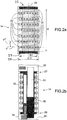
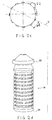
- the Figures 2a, 2b , 2c and 2d represent a first embodiment of the antenna 14.
- the figure 2a represents a schematic external view of the active part of the antenna 14.
- the figures 2b and 2c schematically represent in section the antenna 14 and the figure 2d represents in perspective the antenna 14.
- the antenna 14 is essentially cylindrical. It extends along a longitudinal axis 20. When the antenna 14 is suspended by its own weight from the cable 13, the latter also extends along the longitudinal axis 20.
- the active part of the antenna 14 is formed by sound transmitters and receivers.
- the transmitters are formed of elementary rings of emission of sound waves 21 formed around the axis 20 and the receivers are formed of hydrophones 22 distributed in rings formed around the axis 20.
- An exemplary embodiment of the elementary rings 21 is for example described in the patent EP 0 799 097 B1 .
- the hydrophones 22 are distributed around the axis 20 in a uniform manner.
- the hydrophones 22 are for example insulated in a polyurethane-based resin or immersed in an oil bath contained in a flexible envelope.
- the elementary emission rings 21 and the hydrophone rings 22 are distributed along the same height H measured along the longitudinal axis 20. This distribution over the entire height H allows hydrophones to improve the directivity of acoustic reception on site.
- the figure 2b represents the antenna 14 in section in a plane V containing the longitudinal axis 20, called the vertical plane
- the figure 2c represents the antenna 14 in section in a plane P perpendicular to the longitudinal axis 20, called the horizontal plane.
- a step p1 separating two neighboring hydrophones 22 in the same vertical plane containing the longitudinal axis 20.
- a ring of 12 hydrophones 22 distributed regularly over the perimeter of the ring.
- the different hydrophone rings are advantageously identical.
- a step p2 separating two neighboring hydrophones in the same ring.
- the step p2 separates the phase centers of each of the hydrophones 22. It is defined by the length of the cord on the perimeter of the ring separating two neighboring hydrophones.
- the steps p1 and p2 are advantageously regular. It is however possible to opt for an irregular distribution of the steps p1 and p2.
- the rings 21 and 22 are alternated. More specifically, the elementary emission rings 21 and the hydrophone rings 22 have substantially the same dimensions, in diameter around the axis 20. The elementary emission rings 21 and the hydrophone rings 22 are alternately stacked with on each other.
- the smallest cylindrical volume of axis 20 called minimum volume occupied by the elementary emission rings 21 is marked with the reference 23. Its diameter around the axis 20 is marked D1.
- the smallest cylindrical volume of axis 20 called minimum volume occupied by hydrophones 22 is marked with the reference 24. Its diameter around the axis 20 is marked D2.
- the diameters D1 and D2 are in a ratio less than 30%. In other words, the difference in absolute value between the two diameters D1 and D2 remains less than 30% of the smaller of the two diameters D1 or D2. In the example shown, the diameter D1 is less than the diameter D2. So we have : D 2 - D 1 / D 1 ⁇ 30 %
- this ratio can be less than 20%, even 10% and ideally less than 5%.
- the diameter ratio of the two volumes 23 and 24 is constant whether the antenna is in operation or in a storage position.
- the antenna does not include any folding arm as in the prior art known for this type of antenna operating at low frequency.
- the elementary emission rings 21 and the hydrophone rings 22 form a tube 25 extending along the longitudinal axis 20 between two ends 26 and 27.
- the tube has the largest diameter, D1 or D2 (D2 in the example shown) and is limited by the height H.
- the antenna 14 comprises two structures 28 and 29 closing the tube 25, each at one of the ends 26 and 27 of the tube 25.
- the interior of the tube 25 is then isolated from the medium in which the antenna 14 is diving.
- the cylindrical outer surface of the tube 25 can be covered with an elastomeric material such than for example a polyurethane-based material.
- the two structures 28 and 29 can be one-piece metal parts, for example made from a cast aluminum alloy.
- the upper structure 29 may include vertical fins making it possible to improve the hydrodynamics of the antenna 14 during its movements in the water, in particular when going down and when going up, when the winch 12 is in action.
- the emission rings 21 When the interior of the elementary emission rings 21 is isolated from the medium in which the antenna 14 is immersed, the emission rings 21 operate according to a technology where air is located inside the rings 21. This technology is known in Anglo-Saxon literature under the name of "Air Backed Ring” or ABR.
- the antenna 14 comprises an electronic transmitter 31 connected to the elementary transmission rings 21 and an electronic receiver 32 connected to the hydrophones 22.
- the transmitter 31 and the receiver 32 are arranged inside the tube 25
- Other components can be placed inside the tube 25, such as for example a battery 33. It is also possible to place inside the tube 25 environmental sensors 34.
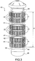
- the figure 3 shows a second embodiment of an antenna 40 according to the invention.
- the hydrophones 22 are arranged concentrically on each of the elementary emission rings 21.
- An elementary emission ring 21 is located inside a ring of hydrophones 22.
- the elementary emission rings 21 and the hydrophone rings 22 are, as in the first embodiment, distributed along the height H.
- the elementary emission rings 21 are in contact with each other.
- the elementary emission rings 21 then occupy the entire height H. It is the same for the hydrophone rings 22. This gives an antenna 40 very compact in height.
- the tube 25 can, as before, be sealed and the interior of the tube 25 can be used to have electronic equipment there.
- the elementary emission rings 21 then operate according to ABR technology.
- the antenna 40 comprises openings 41 arranged between the elementary emission rings 21. These openings allow the water, in which the antenna 40 is soaked, to circulate along internal walls 42 of the elementary rings 21.
- the emission rings 21 When the interior of the elementary emission rings 21 is immersed in the medium in which the antenna 40 is immersed, the emission rings 21 operate according to a technology or water circulates freely around the emission ring 21. This technology is known in Anglo-Saxon literature under the name of "Free Flooded Ring” or FFR.
- the antenna 40 comprises several uprights 44 connecting the two structures 28 and 29.
- the emission rings 21 are fixed on the uprights 44.
- the openings 41 are radial. It is also possible to make these openings in structures 28 and 29.
- the internal space of the emission rings 21 is no longer available to have electronic equipment there which can be placed in watertight compartments made in structures 28 and 29.
- the FFR technology can be implemented in the first embodiment shown using the Figures 2a, 2b and 2c by providing one or more openings for communicating the inside of the tube 25 and the outside.
- the figure 4 shows a third embodiment of an antenna 50 according to the invention.
- the hydrophones 22 are not arranged in rings but on bars 51 fixed to the emission rings 21.
- the bars 51 may be parallel to the longitudinal axis 20. In this embodiment, it is possible to keep the uprights 44 separate from the bars 51.
- the bars 51 can be used to connect the two structures 28 and 29 and replace the uprights 44.
- the bars 51 can be arranged inside or outside of the emission rings 21.
- the abandonment of the deployable antenna principle leads to a reduction in the diameter of the antenna 14, therefore a widening of the main lobe of the directivity diagram of the channel formed by summing the signals from the hydrophones 22 after compensation for the propagation delays for a signal arriving in the set direction.
- the width at -3 dB of this diagram in a horizontal plane perpendicular to the axis 20 thus passes from 22 ° to 52 °, when one passes from a cylindrical antenna with a diameter of 700 mm consisting of 12 arms deployable at a compact antenna with fixed cylindrical geometry with a diameter of 300 mm and consisting of 12 columns as described in the present invention.
- the horizontal pitch in a sub-array is much less than half the wavelength, and that consequently the ambient noise on two neighboring hydrophones is highly correlated, in order to achieve a lane formation which maximizes the signal to noise ratio, such lane formation being different from the previous conventional lane formation which maximizes the signal to noise ratio when the noise is spatially decorrelated.
- the complex coefficients of the channel formation performed in baseband can be calculated from the noise covariance matrix according to the well-known formalism of adaptive antenna processing. According to the prior art, the covariance matrix can either be calculated from the supposed angular distribution of the ambient noise, or estimated from the antenna signals.
- the gain in signal to noise ratio isotropic that is to say the directivity gain
- the aperture at -3 dB of the directivity diagram in the horizontal plane is reduced to 23 °, which brings the antenna directivity gain compact at 2 dB above that of the deployable antenna.
- the same adaptive processing on the deployable antenna only saves a little more than 1 dB due to the low spatial correlation of the noise on this antenna whose pitch between hydrophones is close to half the wavelength.
- the horizontal pitch p2 between two neighboring hydrophones is advantageously less than a third of the wavelength ⁇ / 3, it is around ⁇ / 5 in the example above, as well as the pitch p1 between neighboring hydrophones of the same vertical column.
- the projections of the phase centers of the respective hydrophones are considered.
- the wavelength can vary depending on many parameters such as the temperature and pressure of the water.
- the speed c of a sound wave in water is 1500m / s.
- the horizontal pitch between two hydrophones is the length of the cord between two neighboring hydrophones over the diameter considered.
- the wavelength is 0.375 m.
- the horizontal pitch between two neighboring hydrophones is therefore advantageously less than ⁇ / 3, that is to say: 0.125m.
- a pitch of the order of 0.08 m is obtained, that is to say of the order of ⁇ / 5.
- the gain compared to the conventional treatment of the treatment optimized with respect to the spatial correlation of an isotropic ambient noise becomes greater than 6 dB.
- the gain in directivity due to the tightening of the pitch between hydrophones and the taking into account of the spatial correlation of the isotropic noise in the calculation of the channel formation coefficients is particularly sensitive to the calibration errors of the antenna.
- a channel formation with coefficients calculated according to the same formalism as that optimal for a perfectly calibrated antenna then gives a performance which can be lower than that of conventional processing, reason for which this type of antenna has not been used until now.
- this sensitivity can be remedied by means of a calculation of the coefficients which aims to attenuate the negative effect thereof according to a so-called “robust adaptive” processing formalism which remains based on the noise covariance matrix but holds account for the uncertainty of the antenna response in the direction of the track.
Landscapes
- Engineering & Computer Science (AREA)
- Physics & Mathematics (AREA)
- Radar, Positioning & Navigation (AREA)
- Remote Sensing (AREA)
- Computer Networks & Wireless Communication (AREA)
- General Physics & Mathematics (AREA)
- Acoustics & Sound (AREA)
- Multimedia (AREA)
- Mechanical Engineering (AREA)
- Aviation & Aerospace Engineering (AREA)
- Transducers For Ultrasonic Waves (AREA)
- Measurement Of Velocity Or Position Using Acoustic Or Ultrasonic Waves (AREA)
Description
- La présente invention concerne le domaine général de la détection sonar notamment mise en œuvre dans la lutte anti sous-marine. Elle concerne plus particulièrement le domaine des sonars aéroportés dits "sonars trempés" mis en œuvre depuis un hélicoptère.
- Dans le cadre d'activités de lutte anti sous-marine, pour pouvoir détecter des sous-marins en immersion dans une zone donnée, on a généralement recours à l'utilisation de sonars, en particulier de sonars actifs. Dans ce contexte, le déploiement de sonars à partir de plateformes aériennes, avions ou hélicoptères, s'avère particulièrement efficace car de telles plateformes présentent une grande mobilité par rapport aux sous-marins.
- Ainsi des avions de patrouille maritime déploient des bouées acoustiques, composées de capteurs et parfois d'émetteurs acoustiques et d'un système VHF agissant comme un relais de communication vers l'aéronef.
- De façon analogue, des hélicoptères peuvent être également utilisés pour mettre en œuvre des émetteurs et récepteurs sonars reliés par un câble à leur plateforme, autrement dit à l'hélicoptère. On parle alors de "Sonars trempés". Par la suite, le sous ensemble immergé et relié par le câble est appelé antenne. Il comprend les émetteurs et les récepteurs sonars proprement dits et éventuellement des équipements électroniques associés aux émetteurs et récepteurs. Il peut comprendre également des capteurs d'environnement.
- La mise à l'eau depuis la plateforme, le contrôle en immersion ainsi que la récupération à bord de ces antennes sont effectués au moyen d'un treuil situé à l'intérieur de l'hélicoptère. En plus d'une fonction de déploiement et de récupération de l'antenne, le câble du treuil véhicule généralement les signaux sonar ainsi que l'énergie électrique nécessaire à l'émission acoustique et au fonctionnement des récepteurs. De plus, à bord de l'hélicoptère, on trouve des équipements nécessaires à la génération des signaux acoustiques et au traitement des données acoustiques reçues.
- La discrétion acoustique accrue des sous-marins modernes a nécessité une évolution des techniques de détection employées, vers des sonars de forte puissance fonctionnant à basse fréquence. Cette évolution se traduit par une augmentation des dimensions et de la masse des différents sous ensembles formant le sonar. Par exemple pour l'antenne, le fait d'abaisser sa fréquence de fonctionnement tend à augmenter ses dimensions. On a par exemple développé des antennes dans lesquelles des récepteurs d'ondes sonores ou hydrophones sont disposés sur des bras que l'on déploie lors du fonctionnement. Entre les phases de fonctionnement du sonar, les bras sont repliés et l'antenne, remontée par le treuil, dans une position dite de stockage, prend place à l'intérieur de l'hélicoptère. Il est quelque fois difficile de loger tous les sous ensembles d'un sonar à l'intérieur d'un hélicoptère. L'antenne, généralement cylindrique pour être omnidirectionnelle en gisement et directive en site, est pendue par le câble qui la porte. La plus grande dimension verticale du sonar est contrainte par la hauteur de l'antenne à laquelle il faut ajouter l'accrochage du câble au sommet de l'antenne et au moins en partie une poulie du treuil dont le diamètre est fonction du rayon de courbure minimale que le câble peut subir. Cette dimension doit pouvoir rentrer en hauteur dans l'hélicoptère.
- Concernant l'augmentation de masse des sous ensembles du sonar, celle-ci impacte la durée des missions qu'un porteur peut effectuer avec son sonar.
- Le document
US 2004/052160 A1 décrit un sonar de coque dans lequel une antenne de réception est située autour d'une antenne d'émission. - Le document
US 4 305 141 A décrit une antenne pour sonar trempé comprenant deux zones distinctes superposées : une zone comprenant des anneaux d'émission et une zone comprenant des hydrophones. - Les documents
FR 2 604 530 A1 GB 2 093 996 A - L'invention vise à réduire l'encombrement et la masse de certains sous-ensembles d'un sonar trempé, notamment la masse et la hauteur de l'antenne tout en conservant des performances acoustiques analogues. L'invention vise aussi à réduire la complexité de certains sous-ensembles, notamment de l'antenne. Plus précisément l'invention permet de se passer de bras articulés portant les hydrophones. En évitant de telles pièces mobiles, la fiabilité du sonar s'en trouve améliorée.
- A cet effet, l'invention a pour objet une antenne omnidirectionnelle destinée à équiper un sonar trempé, selon la revendication 1.
- La portée d'une antenne sonar est liée à la fréquence de travail des hydrophones. Une antenne conforme à l'invention fonctionne à une fréquence de travail inférieure à 8 kHz. Autrement dit, les anneaux élémentaires d'émission et les hydrophones fonctionnent à une fréquence de travail inférieure à 8 kHz. Avantageusement, on peut descendre à des fréquences inférieures à 6 kHz voire même inférieure à 4 kHz.
- Il existe des composants acoustiques couramment appelés « Tonpilz » permettant de réaliser à la fois l'émission et la réception d'ondes sonores. Pour des fréquences inférieures à 8 kHz ce type de composant serait beaucoup trop volumineux et l'antenne serait inadaptée à un sonar trempé, notamment embarqué à bord d'un hélicoptère. Pour travailler en basse fréquence, il est avantageux de distinguer les anneaux d'émission des hydrophones.
- Dans l'art antérieur des antennes sonar trempé basse fréquence, notamment dans les antennes cylindriques, les anneaux d'émission occupent un volume distinct de celui des hydrophones. On entend par volume, un espace au contour convexe. Au contraire, selon l'invention les anneaux élémentaires d'émission et les hydrophones sont imbriqués, c'est-à-dire, que les volumes occupés par les anneaux d'émission et le volume occupé par les hydrophones ont des parties communes. La répartition des hydrophones et des anneaux d'émission peut être régulière ou non. Le fait d'imbriquer les anneaux élémentaires d'émission et les anneaux d'hydrophones permet de répartir les émetteurs et les récepteurs acoustiques chacun sur un plus grand volume.
- Plus précisément, on définit un premier volume minimal cylindrique occupé par les anneaux élémentaires d'émission et un second volume minimal cylindrique occupé par les hydrophones. Ces deux volumes sont les plus petits cylindres possibles incluant les anneaux d'émission ou les hydrophones.
- Avantageusement, les projections des centres de phase des hydrophones dans un plan horizontal perpendiculaire à l'axe longitudinal ou dans un plan vertical contenant l'axe longitudinal sont espacées de moins de λ/3, λ étant la longueur d'onde à la fréquence de travail. La réduction de la distance entre hydrophones dans un plan horizontal permet d'améliorer la directivité de l'antenne en gisement et entre hydrophones dans un plan vertical permet d'améliorer la directivité de l'antenne en site. En fonction de la mission à laquelle l'antenne est destinée, on peut choisir de privilégier l'une ou l'autre des directivités. Il est bien entendu possible de réduire la distance entre hydrophones dans les deux plans.
- L'invention a également pour objet un sonar comprenant une antenne selon l'invention. Avantageusement, le sonar comprend un calculateur configuré pour réaliser une formation de voie sonar, des paramètres de la formation de voie étant calculés à partir de la covariance d'un bruit spatialement corrélé selon un formalisme de traitement adaptatif robuste vis-à-vis des erreurs de calibration de l'antenne.
- Il est bien entendu que l'invention n'est pas limitée à un sonar équipant un hélicoptère. Le porteur équipé d'un sonar trempé conforme à l'invention peut être de toute nature. En réduisant la masse d'un sonar trempé, il est par exemple possible d'équiper un drone avec un sonar selon l'invention.
- L'invention sera mieux comprise et d'autres avantages apparaîtront à la lecture de la description détaillée d'un mode de réalisation donné à titre d'exemple, description illustrée par le dessin joint dans lequel :
- la
figure 1 représente un hélicoptère équipé d'un sonar trempé ; - les
figures 2a, 2b ,2c et 2d représentent un premier mode de réalisation d'une antenne appartenant au sonar de lafigure 1 ; - la
figure 3 représente un second mode de réalisation d'une antenne appartenant au sonar de lafigure 1 ; - la
figure 4 représente un troisième mode de réalisation d'une antenne appartenant au sonar de lafigure 1 . - Par souci de clarté, les mêmes éléments porteront les mêmes repères dans les différentes figures.
- La
figure 1 représente un hélicoptère 10 en vol stationnaire au dessus de l'eau. L'hélicoptère 10 est équipé d'un sonar actif trempé 11. Ce type de sonar permet notamment la détection et la classification d'objets sous-marins. - Le sonar 11 comprend essentiellement un treuil 12 installé à bord de l'hélicoptère 10, un câble 13 et une antenne 14 omnidirectionnelle, représentée immergée sur la
figure 1 . L'antenne 14 est suspendue au câble 13 et le treuil 12 permet de dérouler et d'enrouler le câble 13 en fonction de la profondeur à laquelle on souhaite immerger l'antenne 14. Le treuil permet également de remonter l'antenne 14 à l'intérieur de l'hélicoptère 10. Le sonar 11 comprend également des équipements électroniques non représentés et embarqués à bord de l'hélicoptère 10. Les équipements permettent de faire fonctionner le sonar, notamment pour la génération d'onde sonores et pour l'exploitation des ondes reçues en écho des ondes émises. Les équipements permettent également d'alimenter l'antenne 14 en énergie électrique. - Le câble 13 assure une double fonction, tout d'abord un support mécanique de l'antenne 14 et ensuite une liaison électrique entre les équipements électroniques disposés à bord de l'hélicoptère 10 et l'antenne 14. Dans la liaison électrique, on englobe l'alimentation en énergie et la transmission de données vers l'antenne 14 ou en provenance de celle-ci. A titre d'alternative, il est possible de réaliser une antenne 14 autonome sans liaison électrique avec le porteur, le câble étant alors uniquement porteur. L'antenne 14 dispose alors de sa propre source d'énergie électrique, par exemple sous forme d'une batterie. Des moyens de transmission de données, par exemple par onde radio, peuvent être mis en œuvre.
- Le sonar 11 comprend un calculateur 15, par exemple disposé au pied du treuil 12. Le calculateur 15 est configuré pour générer les données transmises à l'antenne 14 et pour traiter les données issues de l'antenne 14. Le calculateur 15 est notamment configuré pour réaliser une formation de voie sonar. Le calculateur 15 est connecté au câble 13 par exemple au travers d'un collecteur tournant placé sur le treuil 12. Le calculateur 15 est avantageusement connecté à un écran permettant de visualiser une image sonar. Le calculateur 15 comprend par exemple une mémoire contenant des instructions et un processeur apte à mettre en œuvre les instructions permettant de calculer la formation de voie sonar.
- Les
figures 2a, 2b ,2c et 2d représentent un premier mode de réalisation de l'antenne 14. Lafigure 2a représente une vue schématique externe de la partie active de l'antenne 14. Lesfigures 2b et2c représentent schématiquement en coupe l'antenne 14 et lafigure 2d représente en perspective l'antenne 14. - L'antenne 14 est essentiellement cylindrique. Elle s'étend selon un axe longitudinal 20. Lorsque l'antenne 14 est suspendue par son propre poids au câble 13, ce dernier s'étend également selon l'axe longitudinal 20.
- La partie active de l'antenne 14 est formée d'émetteurs et de récepteurs sonores. Les émetteurs sont formés d'anneaux élémentaires d'émission d'ondes sonores 21 formés autour de l'axe 20 et les récepteurs sont formés d'hydrophones 22 répartis en anneaux formés autour de l'axe 20. Un exemple de réalisation des anneaux élémentaires d'émission 21 est par exemple décrit dans le brevet
EP 0 799 097 B1 . Les hydrophones 22 sont répartis autour de l'axe 20 de façon uniforme. Les hydrophones 22 sont par exemple isolés dans une résine à base polyuréthane ou immergés dans un bain d'huile contenu dans une enveloppe souple. - Selon l'invention, les anneaux élémentaires d'émission 21 et les anneaux d'hydrophones 22 sont répartis le long d'une même hauteur H mesurée selon l'axe longitudinal 20. Cette répartition sur toute la hauteur H permet pour les hydrophones d'améliorer la directivité de réception acoustique en site.
- La
figure 2b représente l'antenne 14 en coupe dans un plan V contenant l'axe longitudinal 20, appelé plan vertical, et lafigure 2c représente l'antenne 14 en coupe dans un plan P perpendiculaire à l'axe longitudinal 20, appelé plan horizontal. - On peut définir un pas p1 séparant deux hydrophones 22 voisins dans un même plan vertical contenant l'axe longitudinal 20. Sur la figure en coupe 2c apparait un anneau de 12 hydrophones 22 répartis de façon régulière sur le périmètre de l'anneau. Les différents anneaux d'hydrophones sont avantageusement identiques. On définit un pas p2 séparant deux hydrophones voisins dans un même anneau. Le pas p2 sépare les centres de phase de chacun des hydrophones 22. Il est défini par la longueur de la corde sur le périmètre de l'anneau séparant deux hydrophones voisins. Les pas p1 et p2 sont avantageusement réguliers. Il est toutefois possible d'opter pour une répartition irrégulière des pas p1 et p2.
- Dans l'exemple représenté sur les
figures 2a, 2b ,2c et 2d , les anneaux 21 et 22 sont alternés. Plus précisément, les anneaux élémentaires d'émission 21 et les anneaux d'hydrophones 22 ont sensiblement les mêmes dimensions, en diamètre autour de l'axe 20. Les anneaux élémentaires d'émission 21 et les anneaux d'hydrophones 22 sont empilés alternativement les uns sur les autres. - Le plus petit volume cylindrique d'axe 20 appelé volume minimal occupé par les anneaux élémentaires d'émission 21 porte la référence 23. Son diamètre autour de l'axe 20 est repéré D1. Le plus petit volume cylindrique d'axe 20 appelé volume minimal occupé par les hydrophones 22 porte la référence 24. Son diamètre autour de l'axe 20 est repéré D2. Les diamètres D1 et D2 sont dans un rapport inférieur à 30%. Autrement dit, la différence en valeur absolue entre les deux diamètres D1 et D2 reste inférieure à 30% du plus petit des deux diamètres D1 ou D2. Dans l'exemple représenté, Le diamètre D1 est inférieur au diamètre D2. On a donc :

- Avantageusement, afin d'améliorer l'hydrodynamisme de l'antenne ce rapport peut être inférieur à 20%, même à 10% et idéalement inférieur à 5%.
- Le rapport de diamètre des deux volumes 23 et 24 est constant que l'antenne soit en opération ou dans une position de stockage. Autrement dit, l'antenne ne comprend aucun bras dépliant comme dans l'art antérieur connu pour ce type d'antenne fonctionnant en basse fréquence.
- Avantageusement, les anneaux élémentaires d'émission 21 et les anneaux d'hydrophones 22 forment un tube 25 s'étendant selon l'axe longitudinal 20 entre deux extrémités 26 et 27. Le tube possède le diamètre le plus grand, D1 ou D2 (D2 dans l'exemple représenté) et est limité par la hauteur H. L'antenne 14 comprend deux structures 28 et 29 fermant le tube 25, chacune à l'une des extrémités 26 et 27 du tube 25. L'intérieur du tube 25 est alors isolé du milieu dans lequel l'antenne 14 est plongée. Pour assurer une bonne étanchéité du tube 25 sur sa surface extérieure et également pour assurer une protection mécanique des anneaux élémentaires d'émission 21 et des anneaux d'hydrophones 22, la surface extérieure cylindrique du tube 25 peut être recouverte d'un matériau élastomère tel que par exemple un matériau à base de polyuréthane. Les deux structures 28 et 29 peuvent être des pièces métalliques monobloc, par exemple réalisées dans un alliage d'aluminium moulé. La structure supérieure 29 peut comporter des ailettes verticales permettant d'améliorer l'hydrodynamisme de l'antenne 14 lors de ses mouvements dans l'eau, notamment à la descente et à montée, lorsque le treuil 12 est en action.
- Lorsque l'intérieur des anneaux élémentaires d'émission 21 est isolé du milieu dans lequel l'antenne 14 est plongée, les anneaux d'émission 21 fonctionnent selon une technologie où de l'air est situé à l'intérieur des anneaux 21. Cette technologie est connue dans la littérature anglo-saxonne sous le nom de « Air Backed Ring » ou ABR.
- Lorsque le tube 25 est fermé à ses deux extrémités, il forme une enceinte étanche à l'intérieure de laquelle on peut disposer des équipements électroniques. A titre l'exemple, l'antenne 14 comprend un émetteur électronique 31 relié aux anneaux élémentaires d'émission 21 et un récepteur électronique 32 relié aux hydrophones 22. L'émetteur 31 et le récepteur 32 sont disposés à l'intérieur du tube 25. D'autres composants peuvent être disposés à l'intérieur du tube 25, comme par exemple une batterie 33. On peut aussi placer à l'intérieur du tube 25 des capteurs d'environnement 34.
- La
figure 3 représente un second mode de réalisation d'une antenne 40 conforme à l'invention. Dans ce mode de réalisation, les hydrophones 22 sont disposés concentriquement sur chacun des anneaux élémentaires d'émission 21. Un anneau élémentaire d'émission 21 est situé à l'intérieur d'un anneau d'hydrophones 22. Les anneaux élémentaires d'émission 21 et les anneaux d'hydrophones 22 sont, comme dans le premier mode de réalisation, répartis le long de la hauteur H. - Il est possible de disposer les anneaux élémentaires d'émission 21 en contact les uns avec les autres. Les anneaux élémentaires d'émission 21 occupent alors toute la hauteur H. Il en est de même pour les anneaux d'hydrophones 22. On obtient ainsi une antenne 40 très compacte en hauteur. Dans cette disposition, le tube 25 peut, comme précédemment, être étanche et l'intérieur du tube 25 peut être utilisé pour y disposer des équipements électroniques. Les anneaux élémentaires d'émission 21 fonctionnent alors selon la technologie ABR.
- Alternativement, dans ce second mode de réalisation, des parois internes des anneaux élémentaires d'émission 21 sont en contact avec un fluide à l'état liquide. Ce liquide peut être enfermé à l'intérieur du tube 25. La présence de liquide permet d'améliorer les performances acoustiques de l'antenne. Pour bénéficier des avantages de la présence d'un liquide sans augmenter la masse de l'antenne, il est possible de laisser l'eau dans laquelle l'antenne 14 est plongée venir au contact des parois internes des anneaux élémentaires d'émission 21. A cet effet, l'antenne 40 comprend des ouvertures 41 disposées entre les anneaux élémentaires d'émission 21. Ces ouvertures permettent à l'eau, dans laquelle l'antenne 40 est trempée, de circuler le long de parois internes 42 des anneaux élémentaires d'émission 21. Ainsi, lorsque l'antenne 14 n'est pas immergée, l'eau baignant l'intérieur de l'antenne disparait et ne vient pas augmenter la masse de l'antenne. Lorsque l'intérieur des anneaux élémentaires d'émission 21 est baigné dans le milieu dans lequel l'antenne 40 est plongée, les anneaux d'émission 21 fonctionnent selon une technologie ou de l'eau circule librement autour de l'anneau d'émission 21. Cette technologie est connue dans la littérature anglo-saxonne sous le nom de « Free Flooded Ring » ou FFR.
- Pour permettre la présence des ouvertures 41, l'antenne 40 comprend plusieurs montants 44 reliant les deux structures 28 et 29. Les anneaux d'émission 21 sont fixés sur les montants 44.
- Sur la
figure 3 , les ouvertures 41 sont radiales. Il est également possible de réaliser ces ouvertures dans les structures 28 et 29. - En mettant en œuvre la technologie FFR, l'espace interne des anneaux d'émission 21 n'est plus disponible pour y disposer des équipements électroniques qui peuvent être placés dans des compartiments étanches réalisés dans les structures 28 et 29.
- La technologie FFR peut être mise en œuvre dans le premier mode de réalisation représenté à l'aide des
figures 2a, 2b et2c en prévoyant une ou plusieurs ouvertures permettant de faire communiquer l'intérieur du tube 25 et l'extérieur. - La
figure 4 représente un troisième mode de réalisation d'une antenne 50 conforme à l'invention. On retrouve les anneaux d'émission 21 et les deux structures 28 et 29. Dans ce mode de réalisation, les hydrophones 22 ne sont pas disposés en anneaux mais sur des barreaux 51 fixés aux anneaux d'émission 21. Les barreaux 51 peuvent être parallèles à l'axe longitudinal 20. Dans ce mode de réalisation, il est possible de conserver les montants 44 distincts des barreaux 51. Alternativement, les barreaux 51 peuvent être utilisés pour relier les deux structures 28 et 29 et remplacer les montants 44. Les barreaux 51 peuvent être disposés à l'intérieur ou à l'extérieur des anneaux d'émission 21. - Dans les différents modes de réalisation et notamment ceux mettant en œuvre la technologie FFR, il est possible de caréner l'antenne afin d'améliorer son comportement hydrodynamique.
- L'abandon du principe d'antenne déployable entraîne une réduction du diamètre de l'antenne 14, donc un élargissement du lobe principal du diagramme de directivité de la voie formée en sommant les signaux issus des hydrophones 22 après compensation des retards de propagation pour un signal arrivant dans la direction de consigne. A 4 kHz, la largeur à -3 dB de ce diagramme dans un plan horizontal perpendiculaire à l'axe 20 passe ainsi de 22° à 52°, quand on passe d'une antenne cylindrique de diamètre 700 mm constituée de 12 bras déployables à une antenne compacte à géométrie cylindrique fixe de diamètre 300 mm et constituée de 12 colonnes telle que décrite dans la présente invention. Une telle dégradation de la résolution en gisement pose un problème car elle se traduit non seulement par un moindre rapport signal sur bruit en sortie de formation de voie, environ -3 dB en bruit isotrope si les bras de l'antenne déployables et les colonnes de l'antenne compacte sont chacun constitués de 4 hydrophones espacées de 160 mm le long de l'axe vertical 20, mais aussi d'une perte en précision de localisation angulaire d'une cible proche d'un facteur 3.
- Dans l'invention, on tire parti du fait que le pas horizontal dans un sous-réseau est très inférieur à la demi-longueur d'onde, et qu'en conséquence le bruit ambiant sur deux hydrophones voisins est fortement corrélé, pour réaliser une formation de voie qui maximise le rapport signal sur bruit, une telle formation de voie étant différente de la formation de voie conventionnelle précédente qui maximise le rapport signal sur bruit quand le bruit est spatialement décorrélé. Les coefficients complexes de la formation de voie effectuée en bande de base peuvent être calculés à partir de la matrice de covariance du bruit selon le formalisme bien connu du traitement d'antenne adaptatif. Selon l'art connu, la matrice de covariance peut soit être calculée à partir de la distribution angulaire supposée du bruit ambiant, soit estimée à partir des signaux de l'antenne. Par rapport au traitement conventionnel, qui est la cas particulier de ce traitement pour une matrice de covariance du bruit égale au produit de la matrice identité et de la puissance du bruit en sortie d'un hydrophone, le gain en rapport signal sur bruit isotrope, c'est-à-dire le gain de directivité, est augmenté de 5 dB et l'ouverture à -3 dB du diagramme de directivité dans le plan horizontal est ramenée à 23°, ce qui amène la gain de directivité de l'antenne compacte à 2 dB au-dessus de celui de l'antenne déployable. Le même traitement adaptatif sur l'antenne déployable ne fait gagner qu'à peine plus de 1 dB en raison de la faible corrélation spatiale du bruit sur cette antenne dont le pas entre hydrophones est voisin de la demi-longueur d'onde.
- Dans l'art connu du sonar, des groupes d'un petit nombre d'hydrophones ont un pas inférieur à la demi-longueur d'onde et leurs signaux sont combinés au moyen d'une formation de voie de type cardioïde dont le diagramme de directivité a des zéros dans des directions prédéterminées. Une antenne peut être constituée de plusieurs groupes de ce type, le pas entre groupes ayant une valeur proche de la demi-longueur d'onde à la fréquence la plus élevée dans la bande du sonar. Dans l'invention, le pas horizontal p2 entre deux hydrophones voisins est avantageusement inférieur au tiers de la longueur d'onde λ/3, il est d'environ λ/5 dans l'exemple ci-dessus, ainsi que le pas p1 entre hydrophones voisins d'une même colonne verticale. Pour la mesure du pas entre hydrophones, on considère les projections des centres de phase des hydrophones respectifs. La longueur d'onde peut varier en fonction de nombreux paramètres tels que la température et la pression de l'eau. Pour la définition géométrique du pas entre hydrophones, on considère que la vitesse c d'une onde sonore dans l'eau est de 1500m/s. La longueur d'onde λ est donnée par la formule λ = c/f. Pour une antenne à section circulaire, le pas horizontal entre deux hydrophones est la longueur de la corde entre deux hydrophones voisins sur le diamètre considéré. Pour une fréquence de travail de 4kHz, la longueur d'onde est de 0,375m. Pour cette fréquence de travail, le pas horizontal entre deux hydrophones voisins est donc avantageusement inférieur à λ/3, c'est-à-dire : 0,125m. Pour une antenne compacte de 300mm de diamètre travaillant à 4kHz et possédant 12 hydrophones 22 dans chaque plan horizontal, on obtient un pas de l'ordre de 0,08m, c'est à dire de l'ordre de λ/5.
- Si les colonnes de l'antenne compacte de notre exemple sont constituées de 7 hydrophones au pas de 80 mm au lieu de 4 hydrophones au pas de 160 mm comme nous l'avons d'abord supposé, la hauteur entre les deux hydrophones extrêmes d'une colonne restant égale à 480 mm, le gain par rapport au traitement conventionnel du traitement optimisé vis-à-vis de la corrélation spatiale d'un bruit ambiant isotrope devient supérieur à 6 dB.
- Le gain de directivité dû au resserrement du pas entre hydrophones et à la prise en compte de la corrélation spatiale du bruit isotrope dans le calcul des coefficients de formation de voie est particulièrement sensible aux erreurs de calibration de l'antenne. Une formation de voie avec des coefficients calculés selon le même formalisme que celui optimal pour une antenne parfaitement calibrée donne alors une performance qui peut être inférieure à celle du traitement conventionnel, raison pour laquelle ce type d'antenne n'a pas été employé jusqu'à maintenant. Dans l'invention, on peut remédier à cette sensibilité au moyen d'un calcul des coefficients qui vise à en atténuer l'effet négatif selon un formalisme de traitement dit « adaptatif robuste » qui reste basé sur la matrice de covariance du bruit mais tient compte de l'incertitude sur la réponse de l'antenne dans la direction de la voie. Il existe plusieurs variantes de calcul des coefficients. On peut par exemple utiliser le traitement décrit dans l'article « On Robust Capon Beamforming and Diagonal Loading » de Jian LEE publié le 7 juillet 2003 (IEEE Transactions on signal processing, Vol. 51 NO. 7). Par rapport au cas idéal où la calibration de l'antenne est parfaite et pour des erreurs de calibration réalistes, par exemple d'écart type 1 dB en gain et 10° en phase, on perd dans l'exemple précédent l'avantage en gain de directivité de l'antenne compacte de diamètre 300 mm constituée de 12 colonnes de 7 hydrophones sur l'antenne déployable de diamètre 700 mm constituée de 12 bras portant chacun 4 hydrophones, les deux antennes ayant alors des gains de directivité quasi équivalents.
Claims (12)
- Antenne omnidirectionnelle destinée à équiper un sonar trempé (11), l'antenne (14 ; 40, 50) comprenant plusieurs anneaux élémentaires d'émission (21) formés autour d'un axe longitudinal (20) de l'antenne (14 ; 40 ; 50) et plusieurs hydrophones (22) répartis autour de l'axe longitudinal (20), l'antenne (14 ; 40 ; 50) étant destinée à être trempée dans de l'eau, les hydrophones (22) étant distincts des anneaux élémentaires d'émission (21), les hydrophones (22) et les anneaux élémentaires d'émission (21) étant fixés les uns aux autres dans l'antenne (14 ; 40 ; 50), un premier volume minimal cylindrique (23) autour de l'axe longitudinal (20) occupé par les anneaux élémentaires d'émission (21) étant de diamètre D1, un second volume minimal cylindrique (24) autour de l'axe longitudinal (20) occupé par les hydrophones (22) étant de diamètre D2, le rapport de diamètre des deux volumes étant constant que l'antenne (14 ; 40, 50) soit en opération ou dans une position de stockage, caractérisée en ce que les anneaux élémentaires d'émission (21) et les hydrophones (22) sont imbriqués le long d'une même hauteur (H) mesurée selon l'axe longitudinal (20) en ce que les anneaux élémentaires d'émission (21) et les hydrophones (22) fonctionnent à une fréquence de travail inférieure à 8 kHz,
en ce que la différence en valeur absolue entre les deux diamètres D1 et D2 reste inférieure à 30% du plus petit des deux diamètres D1 ou D2,
et en ce que les projections des centres de phase des hydrophones (22) dans un plan horizontal (P) perpendiculaire à l'axe longitudinal (20) ou dans un plan vertical (V) contenant l'axe longitudinal (20) sont espacées d'un pas de moins de λ/3, λ étant la longueur d'onde à la fréquence de travail, les hydrophones (22) étant répartis en anneaux formés autour de l'axe longitudinal (20), dans la plan horizontal (P), le pas (p2) dit pas horizontal entre deux hydrophones (22) est la longueur de la corde entre deux hydrophones voisins sur le diamètre considéré. - Antenne selon la revendication 1, caractérisée en ce que les hydrophones (22) sont disposés sur des barreaux (51) fixés aux anneaux d'émission (21).
- Antenne selon la revendication 1, caractérisée en ce que hydrophones (22) sont répartis en anneaux formés autour de l'axe longitudinal (20).
- Antenne selon la revendication 3, caractérisée en ce que les anneaux élémentaires d'émission (21) et les anneaux d'hydrophones (22) sont alternés sur la hauteur (H).
- Antenne selon l'une quelconque des revendications 1 à 3, caractérisée en ce que les hydrophones (22) sont superposés aux anneaux élémentaires d'émission (21).
- Antenne selon l'une quelconque des revendications 3 ou 4, caractérisée en ce que les anneaux élémentaires d'émission (21) et les anneaux d'hydrophones (22) forment un tube (25) s'étendant selon l'axe longitudinal (20) entre deux extrémités (26, 27), en ce que l'antenne (14, 40, 50) comprend deux structures (28, 29) fermant le tube (25), chacune à l'une des extrémités (26, 27) du tube (25).
- Antenne selon l'une quelconque des revendications 1 à 5, caractérisée en ce que des parois internes des anneaux élémentaires d'émission (21) sont en contact avec un fluide à l'état liquide.
- Antenne selon la revendication 7, caractérisée en ce qu'elle comprend des ouvertures (41) permettant à l'eau dans laquelle l'antenne (40) est trempée de circuler le long de parois internes des anneaux élémentaires d'émission (21).
- Antenne selon la revendication 8, caractérisée en ce que les ouvertures (41) sont disposées entre les anneaux d'émission (21).
- Sonar trempé (11) comprenant un câble (13) et une antenne (14) selon l'une des revendications précédentes, l'antenne (14 ; 40, 50) étant suspendue au câble (13).
- Sonar trempé (11) selon la revendication 10, caractérisé en ce qu'il comprend en outre un treuil (12) permettant d'enrouler et de dérouler le câble (13).
- Sonar trempé (11) comprenant un calculateur (15) et une antenne (14) selon l'une des revendications 1 à 9, le calculateur (15) étant configuré pour réaliser une formation de voie sonar, des paramètres de la formation de voie étant calculés à partir de la covariance d'un bruit spatialement corrélé selon un formalisme de traitement adaptatif robuste vis-à-vis des erreurs de calibration de l'antenne (14).
Applications Claiming Priority (2)
| Application Number | Priority Date | Filing Date | Title |
|---|---|---|---|
| FR1303023A FR3015785B1 (fr) | 2013-12-20 | 2013-12-20 | Antenne omnidirectionnelle compacte pour sonar trempe |
| PCT/EP2014/079002 WO2015092066A1 (fr) | 2013-12-20 | 2014-12-22 | Antenne omnidirectionnelle compacte pour sonar trempe |
Publications (2)
| Publication Number | Publication Date |
|---|---|
| EP3084755A1 EP3084755A1 (fr) | 2016-10-26 |
| EP3084755B1 true EP3084755B1 (fr) | 2020-06-03 |
Family
ID=50828950
Family Applications (1)
| Application Number | Title | Priority Date | Filing Date |
|---|---|---|---|
| EP14825337.0A Active EP3084755B1 (fr) | 2013-12-20 | 2014-12-22 | Antenne omnidirectionnelle compacte pour un sonar trempé |
Country Status (9)
| Country | Link |
|---|---|
| US (1) | US10379207B2 (fr) |
| EP (1) | EP3084755B1 (fr) |
| JP (1) | JP6545686B2 (fr) |
| KR (1) | KR102232745B1 (fr) |
| AU (1) | AU2014369782B2 (fr) |
| CA (1) | CA2934561C (fr) |
| FR (1) | FR3015785B1 (fr) |
| SG (2) | SG11201605064VA (fr) |
| WO (1) | WO2015092066A1 (fr) |
Families Citing this family (17)
| Publication number | Priority date | Publication date | Assignee | Title |
|---|---|---|---|---|
| FR3026569B1 (fr) * | 2014-09-26 | 2017-12-08 | Thales Sa | Antenne omnidirectionnelle |
| KR101835107B1 (ko) * | 2016-10-13 | 2018-04-19 | (주)지이에스 | 어군 탐지용 드론 |
| CN109374108A (zh) * | 2018-10-30 | 2019-02-22 | 中国船舶重工集团公司第七〇九研究所 | 一种适用于大深度开阔湖面的水声测量装置 |
| FR3088731B1 (fr) * | 2018-11-15 | 2022-01-21 | Thales Sa | Multiplexeur de signaux pour sonar |
| JP6915886B2 (ja) * | 2018-12-14 | 2021-08-04 | Necネットワーク・センサ株式会社 | 探査装置および探査方法 |
| FR3097287B1 (fr) | 2019-06-13 | 2022-12-23 | Thales Sa | Dispositif de verouillage d'un objet pendu a un cable |
| FR3097286B1 (fr) | 2019-06-13 | 2022-12-23 | Thales Sa | Dispositif de verrouillage d'un objet le long d'un cáble |
| FR3097333B1 (fr) * | 2019-06-13 | 2021-05-21 | Thales Sa | Sonar trempé à faible trainée |
| CN110988887B (zh) * | 2019-12-25 | 2025-07-08 | 中国船舶重工集团公司七五0试验场 | 一种吊放式搜救声呐装置、系统和方位测量方法 |
| US11682373B2 (en) | 2020-03-25 | 2023-06-20 | Raytheon Company | Interleaf packing and deployment system |
| JP6961266B1 (ja) * | 2020-07-20 | 2021-11-05 | 株式会社amuse oneself | 検出システム、被吊下装置及び検出方法 |
| CN112317286B (zh) * | 2020-09-07 | 2022-06-21 | 江苏大学 | 一种基于仿生原理的水下声波辐射器 |
| AU2022400925A1 (en) | 2021-11-30 | 2024-05-16 | Raytheon Company | Line array winding and deployment system |
| CN114740461B (zh) * | 2022-06-07 | 2022-09-02 | 深圳市晟达通讯设备有限公司 | 一种声呐系统、以及用于该声呐系统的水下定位天线 |
| US12105235B2 (en) | 2022-07-14 | 2024-10-01 | Raytheon Company | Triplet acoustic ring assembly, nested array, and method |
| CN115675775B (zh) * | 2022-11-11 | 2023-10-10 | 中国船舶集团有限公司第七一六研究所 | 一种面向水面舰艇的吊放声纳水下分机集成装置 |
| FR3143046A1 (fr) | 2022-12-08 | 2024-06-14 | Thales | Câble porteur |
Family Cites Families (26)
| Publication number | Priority date | Publication date | Assignee | Title |
|---|---|---|---|---|
| FR2290812A1 (fr) * | 1974-11-08 | 1976-06-04 | Thomson Csf | Transducteur electroacoustique pour immersion profonde |
| US4193129A (en) * | 1976-01-05 | 1980-03-11 | The United States Of America As Represented By The Secretary Of The Navy | Charging circuit for sonar systems |
| US4305141A (en) * | 1978-06-09 | 1981-12-08 | The Stoneleigh Trust | Low-frequency directional sonar systems |
| FR2431419A1 (fr) * | 1978-07-18 | 1980-02-15 | Thomson Csf | Bouee aeroportee largable |
| FR2450193A1 (fr) * | 1979-02-27 | 1980-09-26 | Thomson Csf | Bouee aeroportee largable a declenchement inertiel |
| FR2464179A2 (fr) * | 1979-08-28 | 1981-03-06 | Thomson Csf | Bouee aeroportee largable |
| GB2093996B (en) * | 1980-05-03 | 1984-03-21 | Plessey Co Ltd | Improvements in or relating to sonar arrays |
| US4641290A (en) * | 1984-11-13 | 1987-02-03 | Fred M. Dellorfano, Jr. | Low frequency portable lightweight sonar systems and their method of deployment for greatly increasing the efficiency of submarine surveillance over large areas |
| US5729507A (en) * | 1985-05-13 | 1998-03-17 | Massa Products Corporation | Directional energy receiving systems for use in the indication of the direction of arrival of the received signal |
| FR2604530B1 (fr) * | 1986-09-26 | 1988-12-09 | Thomson Csf | Sonar cylindrique deployable |
| JPH0445358Y2 (fr) * | 1987-05-28 | 1992-10-26 | ||
| JPH0273898U (fr) * | 1988-11-25 | 1990-06-06 | ||
| US5515342A (en) * | 1988-12-22 | 1996-05-07 | Martin Marietta Corporation | Dual frequency sonar transducer assembly |
| JPH02309799A (ja) * | 1989-05-24 | 1990-12-25 | Nec Corp | 送受波器 |
| JP3170348B2 (ja) * | 1992-04-22 | 2001-05-28 | 日本無線株式会社 | 超音波送受波器 |
| JPH07294631A (ja) * | 1994-04-27 | 1995-11-10 | Nec Eng Ltd | ソナー装置用送波器 |
| FR2725684A1 (fr) * | 1994-10-18 | 1996-04-19 | Thomson Csf | Bouee aeroportee largable |
| FR2728755B1 (fr) * | 1994-12-23 | 1997-01-24 | Thomson Csf | Transducteur acoustique en anneau precontraint |
| FR2764160B1 (fr) * | 1997-05-27 | 1999-08-27 | Thomson Marconi Sonar Sas | Transducteur electrodynamique pour acoustique sous-marine |
| FR2776161B1 (fr) * | 1998-03-10 | 2000-05-26 | Thomson Marconi Sonar Sas | Antenne d'emission acoustique annulaire demontable |
| FR2800229B1 (fr) * | 1999-10-22 | 2002-04-05 | Thomson Marconi Sonar Sas | Transducteur acoustique sous-marin a large bande |
| FR2809580B1 (fr) * | 2000-05-26 | 2002-08-30 | Thomson Marconi Sonar Sas | Transducteur electrodynamique pour acoustique sous-marine |
| FR2818081B1 (fr) * | 2000-12-08 | 2003-04-11 | Thomson Marconi Sonar Sas | Sonar de coque pour batiment naval |
| US6671228B1 (en) * | 2002-08-06 | 2003-12-30 | The United States Of America As Represented By The Secretary Of The Navy | Sonar tracking array |
| DE102009018624B3 (de) * | 2009-04-23 | 2010-11-04 | Atlas Elektronik Gmbh | Elektroakustische Unterwasserantenne |
| JP5550092B2 (ja) * | 2009-06-22 | 2014-07-16 | Necネットワーク・センサ株式会社 | 水中画像全方位表示処理装置及び方法 |
-
2013
- 2013-12-20 FR FR1303023A patent/FR3015785B1/fr not_active Expired - Fee Related
-
2014
- 2014-12-22 KR KR1020167019803A patent/KR102232745B1/ko active Active
- 2014-12-22 AU AU2014369782A patent/AU2014369782B2/en active Active
- 2014-12-22 US US15/106,169 patent/US10379207B2/en active Active
- 2014-12-22 CA CA2934561A patent/CA2934561C/fr active Active
- 2014-12-22 EP EP14825337.0A patent/EP3084755B1/fr active Active
- 2014-12-22 JP JP2016541608A patent/JP6545686B2/ja active Active
- 2014-12-22 WO PCT/EP2014/079002 patent/WO2015092066A1/fr not_active Ceased
- 2014-12-22 SG SG11201605064VA patent/SG11201605064VA/en unknown
- 2014-12-22 SG SG10201805295QA patent/SG10201805295QA/en unknown
Non-Patent Citations (1)
| Title |
|---|
| None * |
Also Published As
| Publication number | Publication date |
|---|---|
| SG10201805295QA (en) | 2018-07-30 |
| KR20160101166A (ko) | 2016-08-24 |
| US20160327640A1 (en) | 2016-11-10 |
| AU2014369782A1 (en) | 2016-07-14 |
| AU2014369782B2 (en) | 2019-11-07 |
| FR3015785A1 (fr) | 2015-06-26 |
| SG11201605064VA (en) | 2016-07-28 |
| CA2934561A1 (fr) | 2015-06-25 |
| WO2015092066A1 (fr) | 2015-06-25 |
| JP6545686B2 (ja) | 2019-07-17 |
| KR102232745B1 (ko) | 2021-03-25 |
| US10379207B2 (en) | 2019-08-13 |
| CA2934561C (fr) | 2021-11-16 |
| EP3084755A1 (fr) | 2016-10-26 |
| JP2017509863A (ja) | 2017-04-06 |
| FR3015785B1 (fr) | 2015-12-25 |
Similar Documents
| Publication | Publication Date | Title |
|---|---|---|
| WO2015092066A1 (fr) | Antenne omnidirectionnelle compacte pour sonar trempe | |
| FR2940838A1 (fr) | Procede et dispositif ameliores de prospection sismique marine | |
| CA3086865A1 (fr) | Drone marin de surface et procede de caracterisation d'un milieu subaquatique mis en oeuvre par un tel drone | |
| EP3027499B1 (fr) | Objet marin apte à flotter sur l'eau comprenant un dispositif d'émission et/ou de réception d'ondes électromagnétiques déployable | |
| EP3198586B1 (fr) | Antenne omnidirectionnelle | |
| EP2010937B1 (fr) | Procede pour optimiser l'alimentation d'une antenne lineaire d'emission remorquee pour emettre en mode omnidirectionnel | |
| FR3046129A1 (fr) | ||
| EP3164595B1 (fr) | Installation pour la recuperation de l'energie d'une houle et/ou pour l'attenuation active de ladite houle | |
| WO2012032251A1 (fr) | Procede d'aide a la localisation d'objets immerges emettant un signal acoustique | |
| WO2015097130A1 (fr) | Antenne marine compacte a diversite ajustable | |
| WO2021104986A1 (fr) | Procede de surveillance d'une zone maritime | |
| WO1999064897A1 (fr) | Dispositif d'acquisition sismique a haute resolution | |
| EP0912906B1 (fr) | Procede et dispositif de lutte heliportee contre les mines sous-marines | |
| WO2018114997A1 (fr) | Ligne destinee a etre immergee en milieu aquatique | |
| FR3079620A1 (fr) | Vibrateur marin sismique | |
| FR3076355A1 (fr) | Dispositif de mesure destine a etre immerge | |
| WO2021104988A1 (fr) | Dispositif sonar | |
| EP3871001A1 (fr) | Procede d'utilisation d'un sonar actif a large bande spectrale d'emission et systeme sonar | |
| FR3003359A1 (fr) | Aile pour le remorquage large de sources de recherche geophysique | |
| WO1990013475A1 (fr) | Procede et dispositif d'assistance aux personnes dans l'eau | |
| FR2913147A1 (fr) | Sonar monte sur mat | |
| FR2902194A1 (fr) | Dispositif et procedes associes de mesure de la signature magnetique d'un bateau | |
| FR2902893A1 (fr) | Recepteur sonar a lobes lateraux reduits. | |
| CA3008910A1 (fr) | Bouee de communication et vehicule aquatique comprenant une telle bouee | |
| FR3074473A1 (fr) | Procede de recuperation de dispositifs flottants et dispositif flottant associe |
Legal Events
| Date | Code | Title | Description |
|---|---|---|---|
| PUAI | Public reference made under article 153(3) epc to a published international application that has entered the european phase |
Free format text: ORIGINAL CODE: 0009012 |
|
| 17P | Request for examination filed |
Effective date: 20160617 |
|
| AK | Designated contracting states |
Kind code of ref document: A1 Designated state(s): AL AT BE BG CH CY CZ DE DK EE ES FI FR GB GR HR HU IE IS IT LI LT LU LV MC MK MT NL NO PL PT RO RS SE SI SK SM TR |
|
| AX | Request for extension of the european patent |
Extension state: BA ME |
|
| DAX | Request for extension of the european patent (deleted) | ||
| STAA | Information on the status of an ep patent application or granted ep patent |
Free format text: STATUS: EXAMINATION IS IN PROGRESS |
|
| 17Q | First examination report despatched |
Effective date: 20180125 |
|
| GRAP | Despatch of communication of intention to grant a patent |
Free format text: ORIGINAL CODE: EPIDOSNIGR1 |
|
| STAA | Information on the status of an ep patent application or granted ep patent |
Free format text: STATUS: GRANT OF PATENT IS INTENDED |
|
| RIC1 | Information provided on ipc code assigned before grant |
Ipc: G01S 7/521 20060101ALI20191203BHEP Ipc: G10K 11/00 20060101AFI20191203BHEP |
|
| INTG | Intention to grant announced |
Effective date: 20200103 |
|
| RIN1 | Information on inventor provided before grant (corrected) |
Inventor name: ANDREIS, DANIEL Inventor name: LAGIER, YVES Inventor name: SERNIT, ERIC Inventor name: LARDAT, RAPHAEL Inventor name: BILLON, DIDIER Inventor name: SEITE, FRANCOIS |
|
| GRAS | Grant fee paid |
Free format text: ORIGINAL CODE: EPIDOSNIGR3 |
|
| GRAJ | Information related to disapproval of communication of intention to grant by the applicant or resumption of examination proceedings by the epo deleted |
Free format text: ORIGINAL CODE: EPIDOSDIGR1 |
|
| GRAL | Information related to payment of fee for publishing/printing deleted |
Free format text: ORIGINAL CODE: EPIDOSDIGR3 |
|
| STAA | Information on the status of an ep patent application or granted ep patent |
Free format text: STATUS: EXAMINATION IS IN PROGRESS |
|
| GRAR | Information related to intention to grant a patent recorded |
Free format text: ORIGINAL CODE: EPIDOSNIGR71 |
|
| STAA | Information on the status of an ep patent application or granted ep patent |
Free format text: STATUS: GRANT OF PATENT IS INTENDED |
|
| GRAA | (expected) grant |
Free format text: ORIGINAL CODE: 0009210 |
|
| STAA | Information on the status of an ep patent application or granted ep patent |
Free format text: STATUS: THE PATENT HAS BEEN GRANTED |
|
| INTC | Intention to grant announced (deleted) | ||
| AK | Designated contracting states |
Kind code of ref document: B1 Designated state(s): AL AT BE BG CH CY CZ DE DK EE ES FI FR GB GR HR HU IE IS IT LI LT LU LV MC MK MT NL NO PL PT RO RS SE SI SK SM TR |
|
| INTG | Intention to grant announced |
Effective date: 20200429 |
|
| REG | Reference to a national code |
Ref country code: GB Ref legal event code: FG4D Free format text: NOT ENGLISH |
|
| REG | Reference to a national code |
Ref country code: AT Ref legal event code: REF Ref document number: 1277848 Country of ref document: AT Kind code of ref document: T Effective date: 20200615 Ref country code: CH Ref legal event code: EP |
|
| REG | Reference to a national code |
Ref country code: DE Ref legal event code: R096 Ref document number: 602014066305 Country of ref document: DE |
|
| REG | Reference to a national code |
Ref country code: LT Ref legal event code: MG4D |
|
| PG25 | Lapsed in a contracting state [announced via postgrant information from national office to epo] |
Ref country code: FI Free format text: LAPSE BECAUSE OF FAILURE TO SUBMIT A TRANSLATION OF THE DESCRIPTION OR TO PAY THE FEE WITHIN THE PRESCRIBED TIME-LIMIT Effective date: 20200603 Ref country code: SE Free format text: LAPSE BECAUSE OF FAILURE TO SUBMIT A TRANSLATION OF THE DESCRIPTION OR TO PAY THE FEE WITHIN THE PRESCRIBED TIME-LIMIT Effective date: 20200603 Ref country code: LT Free format text: LAPSE BECAUSE OF FAILURE TO SUBMIT A TRANSLATION OF THE DESCRIPTION OR TO PAY THE FEE WITHIN THE PRESCRIBED TIME-LIMIT Effective date: 20200603 Ref country code: NO Free format text: LAPSE BECAUSE OF FAILURE TO SUBMIT A TRANSLATION OF THE DESCRIPTION OR TO PAY THE FEE WITHIN THE PRESCRIBED TIME-LIMIT Effective date: 20200903 Ref country code: GR Free format text: LAPSE BECAUSE OF FAILURE TO SUBMIT A TRANSLATION OF THE DESCRIPTION OR TO PAY THE FEE WITHIN THE PRESCRIBED TIME-LIMIT Effective date: 20200904 |
|
| REG | Reference to a national code |
Ref country code: NL Ref legal event code: MP Effective date: 20200603 |
|
| PG25 | Lapsed in a contracting state [announced via postgrant information from national office to epo] |
Ref country code: RS Free format text: LAPSE BECAUSE OF FAILURE TO SUBMIT A TRANSLATION OF THE DESCRIPTION OR TO PAY THE FEE WITHIN THE PRESCRIBED TIME-LIMIT Effective date: 20200603 Ref country code: LV Free format text: LAPSE BECAUSE OF FAILURE TO SUBMIT A TRANSLATION OF THE DESCRIPTION OR TO PAY THE FEE WITHIN THE PRESCRIBED TIME-LIMIT Effective date: 20200603 Ref country code: HR Free format text: LAPSE BECAUSE OF FAILURE TO SUBMIT A TRANSLATION OF THE DESCRIPTION OR TO PAY THE FEE WITHIN THE PRESCRIBED TIME-LIMIT Effective date: 20200603 Ref country code: BG Free format text: LAPSE BECAUSE OF FAILURE TO SUBMIT A TRANSLATION OF THE DESCRIPTION OR TO PAY THE FEE WITHIN THE PRESCRIBED TIME-LIMIT Effective date: 20200903 |
|
| REG | Reference to a national code |
Ref country code: AT Ref legal event code: MK05 Ref document number: 1277848 Country of ref document: AT Kind code of ref document: T Effective date: 20200603 |
|
| PG25 | Lapsed in a contracting state [announced via postgrant information from national office to epo] |
Ref country code: NL Free format text: LAPSE BECAUSE OF FAILURE TO SUBMIT A TRANSLATION OF THE DESCRIPTION OR TO PAY THE FEE WITHIN THE PRESCRIBED TIME-LIMIT Effective date: 20200603 Ref country code: AL Free format text: LAPSE BECAUSE OF FAILURE TO SUBMIT A TRANSLATION OF THE DESCRIPTION OR TO PAY THE FEE WITHIN THE PRESCRIBED TIME-LIMIT Effective date: 20200603 |
|
| PG25 | Lapsed in a contracting state [announced via postgrant information from national office to epo] |
Ref country code: EE Free format text: LAPSE BECAUSE OF FAILURE TO SUBMIT A TRANSLATION OF THE DESCRIPTION OR TO PAY THE FEE WITHIN THE PRESCRIBED TIME-LIMIT Effective date: 20200603 Ref country code: SM Free format text: LAPSE BECAUSE OF FAILURE TO SUBMIT A TRANSLATION OF THE DESCRIPTION OR TO PAY THE FEE WITHIN THE PRESCRIBED TIME-LIMIT Effective date: 20200603 Ref country code: CZ Free format text: LAPSE BECAUSE OF FAILURE TO SUBMIT A TRANSLATION OF THE DESCRIPTION OR TO PAY THE FEE WITHIN THE PRESCRIBED TIME-LIMIT Effective date: 20200603 Ref country code: IT Free format text: LAPSE BECAUSE OF FAILURE TO SUBMIT A TRANSLATION OF THE DESCRIPTION OR TO PAY THE FEE WITHIN THE PRESCRIBED TIME-LIMIT Effective date: 20200603 Ref country code: RO Free format text: LAPSE BECAUSE OF FAILURE TO SUBMIT A TRANSLATION OF THE DESCRIPTION OR TO PAY THE FEE WITHIN THE PRESCRIBED TIME-LIMIT Effective date: 20200603 Ref country code: PT Free format text: LAPSE BECAUSE OF FAILURE TO SUBMIT A TRANSLATION OF THE DESCRIPTION OR TO PAY THE FEE WITHIN THE PRESCRIBED TIME-LIMIT Effective date: 20201006 Ref country code: ES Free format text: LAPSE BECAUSE OF FAILURE TO SUBMIT A TRANSLATION OF THE DESCRIPTION OR TO PAY THE FEE WITHIN THE PRESCRIBED TIME-LIMIT Effective date: 20200603 Ref country code: AT Free format text: LAPSE BECAUSE OF FAILURE TO SUBMIT A TRANSLATION OF THE DESCRIPTION OR TO PAY THE FEE WITHIN THE PRESCRIBED TIME-LIMIT Effective date: 20200603 |
|
| PG25 | Lapsed in a contracting state [announced via postgrant information from national office to epo] |
Ref country code: IS Free format text: LAPSE BECAUSE OF FAILURE TO SUBMIT A TRANSLATION OF THE DESCRIPTION OR TO PAY THE FEE WITHIN THE PRESCRIBED TIME-LIMIT Effective date: 20201003 Ref country code: PL Free format text: LAPSE BECAUSE OF FAILURE TO SUBMIT A TRANSLATION OF THE DESCRIPTION OR TO PAY THE FEE WITHIN THE PRESCRIBED TIME-LIMIT Effective date: 20200603 Ref country code: SK Free format text: LAPSE BECAUSE OF FAILURE TO SUBMIT A TRANSLATION OF THE DESCRIPTION OR TO PAY THE FEE WITHIN THE PRESCRIBED TIME-LIMIT Effective date: 20200603 |
|
| REG | Reference to a national code |
Ref country code: DE Ref legal event code: R097 Ref document number: 602014066305 Country of ref document: DE |
|
| PLBE | No opposition filed within time limit |
Free format text: ORIGINAL CODE: 0009261 |
|
| STAA | Information on the status of an ep patent application or granted ep patent |
Free format text: STATUS: NO OPPOSITION FILED WITHIN TIME LIMIT |
|
| PG25 | Lapsed in a contracting state [announced via postgrant information from national office to epo] |
Ref country code: DK Free format text: LAPSE BECAUSE OF FAILURE TO SUBMIT A TRANSLATION OF THE DESCRIPTION OR TO PAY THE FEE WITHIN THE PRESCRIBED TIME-LIMIT Effective date: 20200603 |
|
| 26N | No opposition filed |
Effective date: 20210304 |
|
| PG25 | Lapsed in a contracting state [announced via postgrant information from national office to epo] |
Ref country code: SI Free format text: LAPSE BECAUSE OF FAILURE TO SUBMIT A TRANSLATION OF THE DESCRIPTION OR TO PAY THE FEE WITHIN THE PRESCRIBED TIME-LIMIT Effective date: 20200603 |
|
| REG | Reference to a national code |
Ref country code: CH Ref legal event code: PL |
|
| PG25 | Lapsed in a contracting state [announced via postgrant information from national office to epo] |
Ref country code: MC Free format text: LAPSE BECAUSE OF FAILURE TO SUBMIT A TRANSLATION OF THE DESCRIPTION OR TO PAY THE FEE WITHIN THE PRESCRIBED TIME-LIMIT Effective date: 20200603 |
|
| REG | Reference to a national code |
Ref country code: BE Ref legal event code: MM Effective date: 20201231 |
|
| PG25 | Lapsed in a contracting state [announced via postgrant information from national office to epo] |
Ref country code: IE Free format text: LAPSE BECAUSE OF NON-PAYMENT OF DUE FEES Effective date: 20201222 Ref country code: LU Free format text: LAPSE BECAUSE OF NON-PAYMENT OF DUE FEES Effective date: 20201222 |
|
| PG25 | Lapsed in a contracting state [announced via postgrant information from national office to epo] |
Ref country code: CH Free format text: LAPSE BECAUSE OF NON-PAYMENT OF DUE FEES Effective date: 20201231 Ref country code: LI Free format text: LAPSE BECAUSE OF NON-PAYMENT OF DUE FEES Effective date: 20201231 |
|
| PG25 | Lapsed in a contracting state [announced via postgrant information from national office to epo] |
Ref country code: MT Free format text: LAPSE BECAUSE OF FAILURE TO SUBMIT A TRANSLATION OF THE DESCRIPTION OR TO PAY THE FEE WITHIN THE PRESCRIBED TIME-LIMIT Effective date: 20200603 Ref country code: CY Free format text: LAPSE BECAUSE OF FAILURE TO SUBMIT A TRANSLATION OF THE DESCRIPTION OR TO PAY THE FEE WITHIN THE PRESCRIBED TIME-LIMIT Effective date: 20200603 |
|
| PG25 | Lapsed in a contracting state [announced via postgrant information from national office to epo] |
Ref country code: MK Free format text: LAPSE BECAUSE OF FAILURE TO SUBMIT A TRANSLATION OF THE DESCRIPTION OR TO PAY THE FEE WITHIN THE PRESCRIBED TIME-LIMIT Effective date: 20200603 |
|
| PG25 | Lapsed in a contracting state [announced via postgrant information from national office to epo] |
Ref country code: BE Free format text: LAPSE BECAUSE OF NON-PAYMENT OF DUE FEES Effective date: 20201231 |
|
| P01 | Opt-out of the competence of the unified patent court (upc) registered |
Effective date: 20230606 |
|
| PGFP | Annual fee paid to national office [announced via postgrant information from national office to epo] |
Ref country code: DE Payment date: 20251119 Year of fee payment: 12 |
|
| PGFP | Annual fee paid to national office [announced via postgrant information from national office to epo] |
Ref country code: GB Payment date: 20251113 Year of fee payment: 12 |
|
| PGFP | Annual fee paid to national office [announced via postgrant information from national office to epo] |
Ref country code: FR Payment date: 20251124 Year of fee payment: 12 |
|
| PGFP | Annual fee paid to national office [announced via postgrant information from national office to epo] |
Ref country code: TR Payment date: 20251219 Year of fee payment: 12 |