EP3084071B1 - Zellstoffherstellungsanordnung und -verfahren - Google Patents
Zellstoffherstellungsanordnung und -verfahren Download PDFInfo
- Publication number
- EP3084071B1 EP3084071B1 EP14871933.9A EP14871933A EP3084071B1 EP 3084071 B1 EP3084071 B1 EP 3084071B1 EP 14871933 A EP14871933 A EP 14871933A EP 3084071 B1 EP3084071 B1 EP 3084071B1
- Authority
- EP
- European Patent Office
- Prior art keywords
- mantle
- support structure
- dewatering
- envelope
- radius
- Prior art date
- Legal status (The legal status is an assumption and is not a legal conclusion. Google has not performed a legal analysis and makes no representation as to the accuracy of the status listed.)
- Active
Links
Images



Classifications
-
- B—PERFORMING OPERATIONS; TRANSPORTING
- B01—PHYSICAL OR CHEMICAL PROCESSES OR APPARATUS IN GENERAL
- B01D—SEPARATION
- B01D33/00—Filters with filtering elements which move during the filtering operation
- B01D33/06—Filters with filtering elements which move during the filtering operation with rotary cylindrical filtering surfaces, e.g. hollow drums
- B01D33/067—Construction of the filtering drums, e.g. mounting or sealing arrangements
-
- B—PERFORMING OPERATIONS; TRANSPORTING
- B01—PHYSICAL OR CHEMICAL PROCESSES OR APPARATUS IN GENERAL
- B01D—SEPARATION
- B01D33/00—Filters with filtering elements which move during the filtering operation
- B01D33/06—Filters with filtering elements which move during the filtering operation with rotary cylindrical filtering surfaces, e.g. hollow drums
- B01D33/073—Filters with filtering elements which move during the filtering operation with rotary cylindrical filtering surfaces, e.g. hollow drums arranged for inward flow filtration
-
- B—PERFORMING OPERATIONS; TRANSPORTING
- B30—PRESSES
- B30B—PRESSES IN GENERAL
- B30B9/00—Presses specially adapted for particular purposes
- B30B9/02—Presses specially adapted for particular purposes for squeezing-out liquid from liquid-containing material, e.g. juice from fruits, oil from oil-containing material
- B30B9/20—Presses specially adapted for particular purposes for squeezing-out liquid from liquid-containing material, e.g. juice from fruits, oil from oil-containing material using rotary pressing members, other than worms or screws, e.g. rollers, rings, discs
-
- D—TEXTILES; PAPER
- D21—PAPER-MAKING; PRODUCTION OF CELLULOSE
- D21C—PRODUCTION OF CELLULOSE BY REMOVING NON-CELLULOSE SUBSTANCES FROM CELLULOSE-CONTAINING MATERIALS; REGENERATION OF PULPING LIQUORS; APPARATUS THEREFOR
- D21C9/00—After-treatment of cellulose pulp, e.g. of wood pulp, or cotton linters ; Treatment of dilute or dewatered pulp or process improvement taking place after obtaining the raw cellulosic material and not provided for elsewhere
- D21C9/02—Washing ; Displacing cooking or pulp-treating liquors contained in the pulp by fluids, e.g. wash water or other pulp-treating agents
- D21C9/06—Washing ; Displacing cooking or pulp-treating liquors contained in the pulp by fluids, e.g. wash water or other pulp-treating agents in filters ; Washing of concentrated pulp, e.g. pulp mats, on filtering surfaces
-
- D—TEXTILES; PAPER
- D21—PAPER-MAKING; PRODUCTION OF CELLULOSE
- D21C—PRODUCTION OF CELLULOSE BY REMOVING NON-CELLULOSE SUBSTANCES FROM CELLULOSE-CONTAINING MATERIALS; REGENERATION OF PULPING LIQUORS; APPARATUS THEREFOR
- D21C9/00—After-treatment of cellulose pulp, e.g. of wood pulp, or cotton linters ; Treatment of dilute or dewatered pulp or process improvement taking place after obtaining the raw cellulosic material and not provided for elsewhere
- D21C9/18—De-watering; Elimination of cooking or pulp-treating liquors from the pulp
-
- D—TEXTILES; PAPER
- D21—PAPER-MAKING; PRODUCTION OF CELLULOSE
- D21F—PAPER-MAKING MACHINES; METHODS OF PRODUCING PAPER THEREON
- D21F1/00—Wet end of machines for making continuous webs of paper
- D21F1/48—Suction apparatus
- D21F1/50—Suction boxes with rolls
-
- D—TEXTILES; PAPER
- D21—PAPER-MAKING; PRODUCTION OF CELLULOSE
- D21F—PAPER-MAKING MACHINES; METHODS OF PRODUCING PAPER THEREON
- D21F1/00—Wet end of machines for making continuous webs of paper
- D21F1/66—Pulp catching, de-watering, or recovering; Re-use of pulp-water
- D21F1/74—Pulp catching, de-watering, or recovering; Re-use of pulp-water using cylinders
- D21F1/76—Pulp catching, de-watering, or recovering; Re-use of pulp-water using cylinders with suction
-
- D—TEXTILES; PAPER
- D21—PAPER-MAKING; PRODUCTION OF CELLULOSE
- D21F—PAPER-MAKING MACHINES; METHODS OF PRODUCING PAPER THEREON
- D21F3/00—Press section of machines for making continuous webs of paper
- D21F3/02—Wet presses
- D21F3/10—Suction rolls, e.g. couch rolls
- D21F3/105—Covers thereof
-
- D—TEXTILES; PAPER
- D21—PAPER-MAKING; PRODUCTION OF CELLULOSE
- D21F—PAPER-MAKING MACHINES; METHODS OF PRODUCING PAPER THEREON
- D21F5/00—Dryer section of machines for making continuous webs of paper
- D21F5/02—Drying on cylinders
- D21F5/021—Construction of the cylinders
Definitions
- the present document relates in general to fibre dewatering devices in pulp production and in particular to dewatering roll arrangements.
- dewatering of the pulp may be performed from an inlet pulp concentration of 2-10 % by weight to an output pulp concentration of 20-50 % by weight.
- One type of dewatering device is the twin-roll dewatering device.
- the fibre suspension is brought into contact with the mantle plate of a roll.
- the mantle surface is typically perforated with dewatering channels in a relatively dense pattern.
- Two such rolls are rotated in opposite directions to bring the fibre suspension into a small gap between the rolls.
- the water is thereby pressed out from the suspension through the dewatering channels of the mantle plate and into flow paths within the structures of the rolls.
- the majority of the fibres remain outside the mantle and a pulp with much lower water content exits in the small gap on the other side.
- the dewatered liquid is typically transported axially along the rolls and exits the device in the vicinity of one or both of the roll ends.
- the dewatering efficiency depends to a high degree on the nip between the rolls.
- the gap at the middle parts of the rolls will therefore be somewhat larger than the gap in the vicinity of the ends of the rolls. For short rolls, such bending of the rolls may be small enough to be neglected or at least acceptable.
- a dewatering roll comprises a roll body, a mantle support structure and a mantle.
- the mantle support structure is attached, in a radial direction, around the roll body.
- the mantle is attached, in the radial direction, against an outer surface of the mantle support structure.
- the mantle has a plurality of through holes constituting mantle flow paths from an, in the radial direction, outer surface of the mantle to an, in the radial direction, inner surface of the mantle.
- the mantle support structure presents support flow paths from the outer surface of the mantle support structure. The support flow paths are in fluid contact with the mantle flow paths.
- the outer surface of the mantle support structure has a static geometric shape defining an envelope having a smaller radius in vicinity of each axial end of the mantle support structure than in vicinity of a centre of the mantle support structure. Thereby, the inner surface of the mantle assumes the shape of the envelope.
- a dewatering press comprises at least one dewatering roll according to the first aspect.
- a method for producing a dewatering roll comprises providing of a mantle support structure with support flow paths from an, in a radial direction, outer surface of the mantle support structure.
- the mantle support structure is attached around a roll body.
- a mantle is provided with a plurality of through holes constituting mantle flow paths from an, in the radial direction, outer surface of the mantle to an, in the radial direction, inner surface of the mantle.
- the outer surface of the mantle support structure is formed to obtain a static geometric shape defining an envelope having a smaller radius in vicinity of each axial end of the mantle support structure than in vicinity of a centre of the mantle support structure.
- the mantle is fitted against the outer surface of the mantle support structure.
- the support flow paths are thereby brought in fluid contact with the mantle flow paths.
- the forming of the outer surface of the mantle support structure is performed before fitting the mantle against the outer surface of the mantle support structure.
- Fig. 1 illustrates schematically a twin-roll press 1.
- the twin-roll press 1 comprises two dewatering rolls 10.
- Each dewatering roll 10 has a mantle 40, which is perforated by holes in a radial direction.
- the dewatering rolls 10 are rotating in opposite directions, indicated by the arrows r.
- Fibre suspension 3, e.g. pulp suspension, is entered by a suspension inlet 2 into an enclosing volume 11 provided around, in a tangential direction, at least a part of the respective dewatering roll 10.
- the enclosing volumes 11 of the two dewatering rolls 10 are merging close to a nip section 6 between the dewatering rolls 10.
- the dewatering rolls are positioned at a predetermined distance from each other, leaving a gap within the nip section 6.
- the suspension 3 entered into the enclosing volume 11 is transported by the rotation of the dewatering rolls 10 along in the rotation. Most of the free liquids of the suspension 3 entered into the enclosing volume 11 can during this transportation pass through, indicated by arrows 7, the holes of the mantle 40, due to the vat pressure used when entering the suspension 3.
- the suspension 3 reaches the nip section 6 the volumes is reduced and the suspension will be exposed for a load, pressing the suspension towards the mantles 40 of the dewatering rolls 10.
- the dewatering rolls are pushed towards each other with a force F. This pressing squeezes the filtrate out of the fibre suspension. A large portion of the remaining liquids in the suspension is thereby forced through the holes of the mantle 40.
- about 70-95 % of the input liquids can be removed in this way, leaving a pulp with a consistency of about 30%.
- a fibre-containing material 8 is provided at the exit from the nip section, which is transported away by suitable transportation means 9.
- a washing liquid 5 can be introduced through a wash liquid inlet 4 into the enclosing volume 11 for displacing "dirty" liquids from the suspension. Note, however, that this washing step is optional.
- Fig. 2 illustrates a part of a dewatering roll 10 in a cross-sectional view.
- the mantle 40 has a large number of through holes 42 constituting mantle flow paths 44 for liquids passing 7 through the mantle 40 from an outer surface 46 into the interior of the dewatering roll 10.
- the mantle 40 is supported by a mantle support structure 30, in this embodiment comprising ring elements 34 attached on support ribs 32 provided in an axial direction.
- the mantle 40 is fitted with an inner surface 48 against an outer surface 36 of the mantle support structure 30.
- the mantle support structure 30 is in turn attached to a roll body 20. The liquids resulting from the dewatering process are thus provided into the interior of the dewatering roll 10 inside the mantle 40.
- the mantle 40 is relatively thin in order to provide low flow resistance through the mantle flow paths 44. Once the liquids exit the mantle flow paths 44, they enter into support flow paths 38 provided by the geometrical structure of the mantle support structure 30. In this embodiment, there are radially directed part flow paths between the ring elements 34 flowing into axially directed part flow paths between the support ribs 32. The support flow paths 38 are thus in fluid contact with the mantle flow paths 44.
- the support flow paths 38 could be provided in other ways.
- the support flow paths 38 could in one alternative e.g. have an axial flow direction in the volumes that are in direct contact with the mantle flow paths.
- the support flow paths 38 could have a substantially radial flow direction, delivering the liquids from the mantle inwards towards the axis of the roll body.
- the roll body could then be arranged for receiving the dewatering liquids, e.g. by channels through the roll body surface, and remove the dewatering liquids from the system, e.g. through a hollow roll body.
- Fig. 3 illustrates schematically a twin-roll press 1, in which two dewatering rolls 10 are pressed together by forces F.
- the fibre suspension in the nip section 6 applies a load, illustrates by the arrows 12 onto the dewatering rolls 10 in a direction out from the nip section 6 perpendicular to the direction of the axes of the dewatering rolls 10.
- the load 12 causes the dewatering rolls 10 to bend, which is illustrated (extremely exaggerated) by the dotted line 13.
- the bending is largest in the middle part 16 of the dewatering rolls 10, in an axial direction A.
- the deflection of the dewatering rolls 10 also influences the local load on the dewatering rolls 10. It has been found in experiments that the local load close to the ends 15 of the dewatering rolls 10 increases whereas the local load in the middle 16 of the dewatering rolls 10 decreases. Since the relationship between actual gap size and local load is highly non-linear, the load close to the ends 15 of the dewatering rolls 10 may increase considerably, thereby increasing the risk for overloading the mantle.
- FIG. 4 schematically illustrates a twin-roll press 1, in which two dewatering rolls 10 are pressed together by forces F.
- the load 12 in the nip section 6 causes the dewatering rolls 10 to deform their cross-sections, illustrated in an extremely exaggerated way by the dotted line 14.
- a straight-forward approach in e.g. paper machines to solve analogous problems is to machine the outer surface of the rolls to assume a slightly differing radius along the axis of the roll.
- the mantle is perforated to provide mantle flow paths.
- the aspect ratio of the hole length to hole diameter has to be kept as low as possible. It is therefore advantageous to have a thin mantle plate.
- a typical thickness is around 3 mm.
- deflections caused by the load can be in the order of several millimetres.
- a machining of the mantle plate thereby becomes impossible.
- using a thick mantle plate that would allow machining depths of a couple of millimetres will instead give rise to mantle flow paths with too high flow resistance.
- the basic solution according to the present invention is based on the idea of leaving the mantle thickness essentially unmodified, but instead provide a static mantle support structure that has the required deflection measures.
- Fig. 5 illustrates one embodiment of a dewatering press, in this embodiment a twin roll press 1 with two dewatering rolls 10.
- Each of the dewatering rolls comprises a roll body 20, a mantle support structure 30 and a mantle 40.
- the mantle support structure 30 is attached, in a radial direction R, around the roll body 20.
- the mantle 40 is attached, in the radial direction R, against an outer surface 36 of the mantle support structure 30.
- the mantle 40 has a plurality of through holes 42 constituting mantle flow paths 44 from an, in the radial direction R, outer surface 46 of the mantle 40 to an, in the radial direction R, inner surface 48 of the mantle 40.
- the mantle support structure 30 presents support flow paths 38 from the outer surface 36 of the mantle support structure 30.
- the support flow paths 38 are in fluid contact with the mantle flow paths 44.
- the structure of the mantle support structure 30 should be as open as possible without any unnecessary disturbing parts.
- the open structure preferably provides flow paths of low flow resistance.
- the exact geometrical composition of the mantle support structure 30 can, however, be varied in very different manners.
- the contact area between the mantle support structure 30 and the mantle 40 has to be kept relatively small, in order to allow the connection of the support flow paths 38 and the mantle flow paths 44.
- the contact surface is less than 1/3 of the mantle surface.
- the actual contact surface pattern can be designed in different ways. In the embodiment of Fig. 5 , the contact is provided in circular paths around the roll body 20.
- contacts directed in an axial direction or as helical structures can also be used.
- contact patterns of mesh types are feasible. The actual pattern of the contact surface is, however, not influencing the basic technical effect of the here presented technology as long as a good connection of the support flow paths 38 and the mantle flow paths 44 is provided.
- mantle flow paths 44 can in different embodiments also be designed in different ways.
- Non-exclusive example can e.g. be different types of slits or holes with circular or non-circular cross-sections.
- the outer surface 36 of the mantle support structure 30 has a static geometric shape defining an envelope having a smaller radius in vicinity of each axial end 15 of the mantle support structure 30 than in vicinity of a centre 16 of the mantle support structure 30.
- the inner surface 48 of the mantle assumes the shape of that envelope.
- the mantle has an essentially uniform thickness in the radial direction.
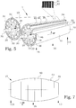
- Fig. 6 illustrates schematically an embodiment of a dewatering roll 10 with the mantle removed.
- the mantle support structure 30 has an outer surface 36 with a geometric shape.
- This geometric shape defines an envelope 39 connecting the outer surface 36 parts.
- This envelope 39 thus corresponds to the shape the mantle assumes when being fitted onto the mantle support structure 30.
- the envelope 39 has a smaller radius in vicinity of each axial end 15 of the mantle support structure 30 than in vicinity of a centre 16 of the mantle support structure 30. Note, that this changing radius is extremely exaggerated in Fig. 6 , in order to be visualized.
- the difference is typically in the order of a fraction of a millimeter up to a couple of millimeters, whereas the dewatering roll 10 length typically is from 0.5 m up to more than 10 m.
- a radius of the envelope 39 is changing monotonously from the centre 16 of the mantle support structure 30 towards each of the axial ends 15 of the mantle support structure 30.
- the envelope 39 is thus preferably given a shape that compensates for deflection and deformation of the dewatering roll 10 at a pre-defined operation load. When being in operation, the changing radius and the deflection and deformation will ideally cancel each other and a more or less constant gap is provided in the nip section.
- the radius of the envelope 39 is not changing monotonously all the way from the centre 16.
- the radius of the envelope 39 is changing monotonously over a major part of the distance from the centre 16 of the mantle support structure 30 towards each of the axial ends 15 of the mantle support structure 30.
- the dewatering press is a twin roll press 1, where both the dewatering rolls 10 are provided with the changing radius according to Fig. 6 .
- one of the dewatering rolls could be manufactured according to prior-art as a straight roll, whereas the other dewatering roll could be given a changing radius compensating for the deflection and deformation of both dewatering rolls. This will give rise to a nip section that is slightly bent between the dewatering rolls, but any disadvantages of having such a bent nip section are expected to be very small. In such a way, the deflection compensation only has to be performed on one of the dewatering rolls, thereby saving production time and complexity.
- a dewatering press may also be designed only having one dewatering roll.
- the counteracting surface can be a non-dewatering roll or more or less any relatively flat surface.
- the same principles about deflection compensation of the dewatering roll can, however, by advantage also be used in such dewatering presses.
- This acceptable deviance from a perfectly compensated deflection also opens up for different shapes of the envelope.
- the envelope shape can thereby be modified from the ideal deflection compensation shape without causing any significant disadvantages.
- the resulting gap of a twin-roll arrangement varies less than 0.2 mm, almost no reduction in dewatering efficiency can be detected. If the resulting gap varies less than 1 mm, the effect on the dewatering efficiency is still small, however, noticeable. Also resulting gap varying less than 2 mm could be used, at least if the absolute measure of the gap is relatively wide.
- the radius of the envelope is manufactured to vary piecewise linearly in the axial direction.
- FIG. 7 an envelope 39 of a mantle support structure is schematically depicted.
- the radius of the envelope 39 decreases piecewise linearly in the axial direction A from the centre 16 of the mantle support structure towards each of the axial ends 15 of the mantle support structure.
- the envelope consists of linearly varying sections 51, connected to each other at the ends thereof.
- an envelope 39 of a mantle support structure of another embodiment is schematically depicted.
- the radius of the envelope is manufactured to be piecewise linearly in the axial direction.
- the radius of the envelope 39 is piecewise constant in the axial direction A.
- the envelope consists of sections 52 having a constant radius. The sections 52 are connected to each other at the ends thereof, thereby creating a step in the radius. By selecting the widths and step sizes of these sections 52 in a suitable manner, the difference in radius compared to an ideal deflection compensating curve 50 can anyway be kept very small. Note that the illustrated changes in radius are extremely exaggerated.
- Fig. 9 illustrated a flow diagram of steps of an embodiment of a method for producing a dewatering roll.
- the procedure starts in step 200.
- a mantle support structure is provided with support flow paths from an, in a radial direction, outer surface of the mantle support structure.
- the mantle support structure is attached around a roll body.
- a mantle is provided with a plurality of through holes. The through holes constitute mantle flow paths from an, in the radial direction, outer surface of the mantle to an, in the radial direction, inner surface of the mantle.
- step 216 the outer surface of the mantle support structure is formed to obtain a static geometric shape defining an envelope having a smaller radius in vicinity of each axial end of the mantle support structure than in vicinity of a centre of the mantle support structure.
- step 218, occurring after step 216 the mantle is fitted against the outer surface of the mantle support structure. The support flow paths are thus brought in fluid contact with the mantle flow paths. The procedure ends in step 299.
- the step of fitting 218 the mantle against the outer surface of the mantle support structure is performed by shrink-fitting.
- the mantle is typically provided with an inner radius that is somewhat smaller than the smallest radius of the portion of the mantle support structure it is intended to cover.
- the mantle is heated, whereby it expands. During this elevated temperature, the mantle is fitted around the mantle support structure and is then allowed to cool down.
- the mantle will be shrink-fitted onto the mantle support structure. This means that the inner surface of the mantle assumes the shape of the envelope as a result of the shrink-fitting.
- the mantle is fitted onto the mantle support structure in sections, whereby the original radius of the mantle is adapted to the respective mantle support structure section. If the changes in radius within such a mantle support structure section is moderate, the mantle can be originally provided before the shrink-fitting with a constant radius, whereby the shrink-fitting will cause the mantle to assume a shape similar to the envelope.
- the step of providing a mantle then comprises shaping the mantle to by its inner surface assume the shape of the envelope.
- the mantle can then be stuck onto the mantle support structure and attached by any appropriate means.
Landscapes
- Engineering & Computer Science (AREA)
- Life Sciences & Earth Sciences (AREA)
- Wood Science & Technology (AREA)
- Mechanical Engineering (AREA)
- Chemical & Material Sciences (AREA)
- Chemical Kinetics & Catalysis (AREA)
- Paper (AREA)
Claims (14)
- Entwässerungswalze (10), umfassend
einen Walzenkörper (20);
eine Mantelstützstruktur (30), die in einer radialen Richtung (R) um den Walzenkörper (20) befestigt ist; und
einen Mantel (40), der in der radialen Richtung (R) an einer Außenfläche (36) der Mandelstützstruktur (30) befestigt ist;
wobei der Mantel (40) eine Vielzahl von Durchgangslöchern (42) aufweist, die Mantelflusswege (44) von einer, in der radialen Richtung (R), Außenfläche (46) des Mantels (40) zu einer, in der radialen Richtung (R), Innenfläche (48) des Mantels (40) darstellen;
wobei die Mantelstützstruktur (30) Stützflusswege (38) von der Außenfläche (36) der Mantelstützstruktur (30) aufweist, wobei die Stützflusswege (38) in Fluidverbindung mit den Mantelflusswegen (44) stehen,
dadurch gekennzeichnet, dass
die Außenfläche (36) der Mantelstützstruktur (30) eine statische geometrische Form aufweist, die eine Hülle (39) mit einem kleineren Radius in der Nähe von jedem axialen Ende (15) der Mantelstützstruktur (30) als in der Nähe eines Mittelpunkts (16) der Mantelstützstruktur (30) aufweist, wobei die Innenfläche (48) des Mantels (40) die Form der Hülle (39) annimmt. - Entwässerungswalze nach Anspruch 1, dadurch gekennzeichnet, dass der Hülle (39) eine Form gegeben wird, die die Ablenkung und Verformung der Entwässerungsrolle (10) bei einer vorbestimmten Betriebslast ausgleicht.
- Entwässerungswalze nach Anspruch 2, dadurch gekennzeichnet, dass der Hülle (39) eine Form mit einem Radius an dem Mittelpunkt (16) gegeben wird, in einer axialen Richtung (A), der mindestens 0,5 mm größer ist als ein Radius, der einem axialen Ende (15) der Mantelstützstruktur (30) nahesteht.
- Entwässerungswalze nach einem der Ansprüche 1 bis 3, dadurch gekennzeichnet, dass sich ein Radius der Hülle (39) über einen großen Teil des Abstands von dem Mittelpunkt (16) der Mantelstützstruktur (30) zu jedem der axialen Enden (15) der Mantelstützstruktur (30) monoton verändert.
- Entwässerungswalze nach Anspruch 4, dadurch gekennzeichnet, dass sich ein Radius der Hülle (39) von dem Mittelpunkt (16) der Mantelstützstruktur (30) zu jedem der axialen Enden (15) der Mantelstützstruktur (30) monoton verändert.
- Entwässerungswalze nach einem der Ansprüche 1 bis 5, dadurch gekennzeichnet, dass der Radius der Hülle (39) in der axialen Richtung (A) stückweise linear variiert.
- Entwässerungswalze nach Anspruch 6, dadurch gekennzeichnet, dass sich der Radius der Hülle (39) von dem Mittelpunkt (16) der Mantelstützstruktur (30) zu jedem der axialen Enden (15) der Mantelstützstruktur (30) in der axialen Richtung (A) stückweise linear verringert.
- Entwässerungswalze nach einem der Ansprüche 1 bis 5, dadurch gekennzeichnet, dass der Radius der Hülle (39) in der axialen Richtung (A) stückweise konstant ist.
- Entwässerungswalze nach einem der Ansprüche 1 bis 8, dadurch gekennzeichnet, dass der Mantel (40) in der radialen Richtung (R) eine im Wesentlichen uniforme Dicke aufweist.
- Entwässerungspresse (1), umfassend mindestens eine Entwässerungswalze (10) nach einem der Ansprüche 1 bis 9.
- Entwässerungspresse nach Anspruch 10, dadurch gekennzeichnet, dass die Entwässerungspresse (1) zwei Entwässerungswalzen (10) nach einem der Ansprüche 1 bis 8 umfasst, die nebeneinander parallel zueinander angeordnet sind.
- Verfahren zum Herstellen einer Entwässerungswalze, umfassend die folgenden Schritte:Bereitstellen (210) einer Mantelstützstruktur mit Stützflusswegen von einer, in einer radialen Richtung, Außenfläche der Mantelstützstruktur;Befestigen (212) der Mantelstützstruktur um einen Walzenkörper;Bereitstellen (214) eines Mantels mit einer Vielzahl von Durchgangslöchern, die Mantelflusswege von einer, in der radialen Richtung, Außenfläche des Mantels zu einer, in der radialen Richtung, Innenfläche des Mantels darstellt;Anpassen (218) des Mantels an die Außenfläche der Mantelstützstruktur;wobei die Stützflusswege in Fluidkontakt mit den Mantelflusswegen gebracht werden,gekennzeichnet durch den folgenden weiteren Schritt:
Bilden (216), vor dem Anpassungsschritt (218), der Außenfläche der Mantelstützstruktur, um eine statische geometrische Form zu erhalten, die eine Hülle mit einem kleineren Radius in der Nähe von jedem axialen Ende der Mantelstützstruktur als in der Nähe eines Mittelpunkts der Mantelstützstruktur aufweist. - Verfahren nach Anspruch 12, dadurch gekennzeichnet, dass der Schritt des Anpassens (218) des Mantels an die Außenfläche der Mantelstützstruktur durch Aufschrumpfen durchgeführt wird, wobei die Innenfläche des Mantels durch das Aufschrumpfen die Form der Hülle annimmt.
- Verfahren nach Anspruch 12, dadurch gekennzeichnet, dass der Schritt des Bereitstellens (214) eines Mantels die Formgebung des Mantels umfasst, so dass seine Innenfläche die Form des Mantels annimmt.
Applications Claiming Priority (2)
| Application Number | Priority Date | Filing Date | Title |
|---|---|---|---|
| SE1351529A SE538068C2 (sv) | 2013-12-19 | 2013-12-19 | Arrangemang och förfarande för massaproduktion |
| PCT/SE2014/051495 WO2015094093A1 (en) | 2013-12-19 | 2014-12-15 | Pulp production arrangement and method |
Publications (3)
| Publication Number | Publication Date |
|---|---|
| EP3084071A1 EP3084071A1 (de) | 2016-10-26 |
| EP3084071A4 EP3084071A4 (de) | 2017-08-02 |
| EP3084071B1 true EP3084071B1 (de) | 2018-08-08 |
Family
ID=53403245
Family Applications (1)
| Application Number | Title | Priority Date | Filing Date |
|---|---|---|---|
| EP14871933.9A Active EP3084071B1 (de) | 2013-12-19 | 2014-12-15 | Zellstoffherstellungsanordnung und -verfahren |
Country Status (7)
| Country | Link |
|---|---|
| US (1) | US10227728B2 (de) |
| EP (1) | EP3084071B1 (de) |
| CN (1) | CN105829603B (de) |
| BR (1) | BR112016014054B1 (de) |
| CA (1) | CA2928826A1 (de) |
| SE (1) | SE538068C2 (de) |
| WO (1) | WO2015094093A1 (de) |
Families Citing this family (4)
| Publication number | Priority date | Publication date | Assignee | Title |
|---|---|---|---|---|
| US11202451B2 (en) * | 2018-05-26 | 2021-12-21 | Oganes MELKONYAN | Culinary device |
| CN109487611B (zh) * | 2018-12-28 | 2021-03-05 | 四川凤生纸业科技股份有限公司 | 一种高效纸浆压滤脱水设备 |
| SE546043C2 (en) * | 2021-09-24 | 2024-04-23 | Valmet Oy | Apparatus for washing cellulose pulp comprising a liquid distributor |
| AT527520B1 (de) | 2023-08-31 | 2025-06-15 | Valmet Technologies Oy | Prozesswasserentwässerungssystem |
Family Cites Families (34)
| Publication number | Priority date | Publication date | Assignee | Title |
|---|---|---|---|---|
| US2191144A (en) * | 1937-12-31 | 1940-02-20 | Beloit Iron Works | Press roll |
| US2338465A (en) * | 1938-05-19 | 1944-01-04 | Downingtown Mfg Co | Suction roll |
| US3590453A (en) * | 1968-06-19 | 1971-07-06 | Metal Tech Inc | Honeycomb roll |
| US3562883A (en) * | 1968-06-26 | 1971-02-16 | Shogo Kobayashi | Suction press roll for papermaking |
| CA973860A (en) | 1971-09-24 | 1975-09-02 | Gerhard W. Dorfel | Supporting-roller reeling apparatus |
| US3991669A (en) * | 1973-01-17 | 1976-11-16 | Imperial Chemical Industries Limited | Calender presses |
| AT333120B (de) * | 1973-11-24 | 1976-11-10 | Voith Gmbh J M | Zylinder fur papiermaschinen od.dgl. |
| US4121968A (en) * | 1977-01-03 | 1978-10-24 | Weyerhaeuser Company | Secondary vacuum box for a rotary vacuum filter |
| US4366025A (en) * | 1981-06-04 | 1982-12-28 | Beloit Corporation | Suction press roll |
| US4683774A (en) * | 1984-03-08 | 1987-08-04 | Delta Elettronica S.R.L. | Bowden cable |
| US4683744A (en) * | 1985-06-18 | 1987-08-04 | Wean United Rolling Mills, Inc. | Flexible edge roll |
| SE454187B (sv) * | 1985-10-31 | 1988-04-11 | Kamyr Ab | Apparat for behandling av fibermaterial |
| SE448311B (sv) * | 1986-04-08 | 1987-02-09 | Sunds Defibrator | Avvattningspress |
| CN86206333U (zh) * | 1986-09-02 | 1987-09-30 | 轻工业部杭州轻工机械设计研究所 | 成对工作辊筒挠度调节机构 |
| FI83841C (fi) * | 1989-04-07 | 1991-09-10 | Salomans Oy | Foerfarande foer kontinuerligt utbyte av vaetskan i en suspension av ett fibroest eller finkornigt material. |
| FI92733C (fi) | 1990-08-15 | 1994-12-27 | Valmet Paper Machinery Inc | Kuumennettava tela |
| US5275024A (en) * | 1992-05-04 | 1994-01-04 | The Black Clawson Company | Paper pulp washing |
| DE4241040A1 (de) * | 1992-12-05 | 1994-06-09 | Voith Gmbh J M | Entwässerungsmaschine |
| FI92734C (fi) * | 1993-02-11 | 1994-12-27 | Valmet Paper Machinery Inc | Menetelmä paperikoneen telan pinnoituksessa ja pinnoitettu paperikoneen tela |
| FI98089C (fi) * | 1995-05-18 | 1997-04-10 | Valmet Corp | Öljynsyöttökanavisto taipumakompensoitua telaa varten |
| AT405420B (de) * | 1997-05-26 | 1999-08-25 | Andritz Patentverwaltung | Vorrichtung zur entwässerung und wäsche von faserstoffsuspensionen |
| SE512876C2 (sv) * | 1999-06-18 | 2000-05-29 | Kvaerner Pulping Tech | Tätningsorgan i en anordning för avvattning av massa |
| SE0102811L (sv) | 2001-08-23 | 2003-04-08 | Metso Paper Inc | Tätning vid pressvalsar |
| CN2500704Y (zh) * | 2001-09-12 | 2002-07-17 | 章丘市造纸机械辅机厂 | 一种双辊置换压榨洗浆机 |
| ITFI20030134A1 (it) | 2003-05-15 | 2004-11-16 | Perini Fabio Spa | Rullo a bombatura variabile per dispositivi di lavorazione di materiale nastriforme continuo e dispositivo comprendente detto rullo |
| US7285180B2 (en) * | 2004-04-19 | 2007-10-23 | Gl&V Management Hungary Kft. | Perforated deck made out of a plurality of segments |
| FI20041518L (fi) | 2004-11-25 | 2006-05-26 | Andritz Oy | Menetelmä ja laite meesan käsittelemiseksi |
| SE528867C2 (sv) * | 2005-07-04 | 2007-03-06 | Metso Paper Inc | Valskropp för pressvals samt valspress innefattande två pressvalsar |
| SE530578C2 (sv) | 2006-11-23 | 2008-07-08 | Metso Paper Inc | Pressvals för tvättning och/eller avvattning av massa och förfarande för tillverkning eller reparation av sådan pressvals |
| SE531844E (sv) * | 2007-12-13 | 2013-06-04 | Metso Paper Inc | Apparat för tvättning och avvattning av massa |
| SE0802029A2 (sv) * | 2008-09-24 | 2010-07-20 | Metso Paper Inc | Apparat för tvättning och/eller avvattning av massa |
| SE0802028A2 (sv) | 2008-09-24 | 2010-07-20 | Metso Paper Inc | Apparat för tvättning och/eller avvattning av massa |
| SE533760C2 (sv) * | 2008-12-19 | 2010-12-28 | Metso Paper Inc | Metod och arrangemang för att sätta fast en vira |
| US8187125B2 (en) | 2009-04-14 | 2012-05-29 | Alexander Kaufman | Tennis throw trainer |
-
2013
- 2013-12-19 SE SE1351529A patent/SE538068C2/sv not_active IP Right Cessation
-
2014
- 2014-12-15 BR BR112016014054-0A patent/BR112016014054B1/pt active IP Right Grant
- 2014-12-15 US US15/102,021 patent/US10227728B2/en active Active
- 2014-12-15 WO PCT/SE2014/051495 patent/WO2015094093A1/en not_active Ceased
- 2014-12-15 CN CN201480068496.4A patent/CN105829603B/zh active Active
- 2014-12-15 EP EP14871933.9A patent/EP3084071B1/de active Active
- 2014-12-15 CA CA2928826A patent/CA2928826A1/en not_active Abandoned
Non-Patent Citations (1)
| Title |
|---|
| None * |
Also Published As
| Publication number | Publication date |
|---|---|
| SE1351529A1 (sv) | 2015-06-20 |
| EP3084071A4 (de) | 2017-08-02 |
| EP3084071A1 (de) | 2016-10-26 |
| CN105829603B (zh) | 2018-09-28 |
| BR112016014054B1 (pt) | 2021-12-21 |
| SE538068C2 (sv) | 2016-02-23 |
| US20160305067A1 (en) | 2016-10-20 |
| BR112016014054A2 (pt) | 2017-08-08 |
| CN105829603A (zh) | 2016-08-03 |
| US10227728B2 (en) | 2019-03-12 |
| CA2928826A1 (en) | 2015-06-25 |
| WO2015094093A1 (en) | 2015-06-25 |
Similar Documents
| Publication | Publication Date | Title |
|---|---|---|
| US10227728B2 (en) | Pulp production arrangement and method | |
| EP2152960B1 (de) | Anordnung zur waschung und entwässerung einer cellulose-pulpe | |
| US4781795A (en) | Heated drum having high thermal flux and belt press using same | |
| EP0302884B1 (de) | Gurt-Walzenpresse | |
| US4758310A (en) | Belt and drum-type pressing apparatus | |
| US8092653B2 (en) | Roll body for a press roll | |
| CA2657627A1 (en) | Twin wire press | |
| CN102159766B (zh) | 用于造纸机、纸板机或薄纸机的压紧单元 | |
| US5971160A (en) | Fibresaver screen basket support | |
| KR101270437B1 (ko) | 실린더 성형기 상의 연장된 카우치 닙 | |
| CN107059459B (zh) | 用于纤维幅材机的辊的铸造轴和配备铸造轴的辊 | |
| EP4132676B1 (de) | Anordnung einer zellstoffverteilungskammer, zellstofffiltergerät und zellstoffeinbringungsverfahren | |
| EP1831456B1 (de) | Rollpresse und rollkörper für pressrolle | |
| EP1807567A1 (de) | Verfahren und vorrichtung mit doppelsiebpresse | |
| WO2000073579A1 (en) | Screen cylinder for a screw press | |
| EP1609907B1 (de) | Breitnipkalander und Verfahren zum Satinieren einer Materialbahn |
Legal Events
| Date | Code | Title | Description |
|---|---|---|---|
| PUAI | Public reference made under article 153(3) epc to a published international application that has entered the european phase |
Free format text: ORIGINAL CODE: 0009012 |
|
| 17P | Request for examination filed |
Effective date: 20160719 |
|
| AK | Designated contracting states |
Kind code of ref document: A1 Designated state(s): AL AT BE BG CH CY CZ DE DK EE ES FI FR GB GR HR HU IE IS IT LI LT LU LV MC MK MT NL NO PL PT RO RS SE SI SK SM TR |
|
| AX | Request for extension of the european patent |
Extension state: BA ME |
|
| DAX | Request for extension of the european patent (deleted) | ||
| A4 | Supplementary search report drawn up and despatched |
Effective date: 20170705 |
|
| RIC1 | Information provided on ipc code assigned before grant |
Ipc: B01D 33/073 20060101ALI20170629BHEP Ipc: D21C 9/06 20060101AFI20170629BHEP Ipc: D21C 9/18 20060101ALI20170629BHEP |
|
| GRAP | Despatch of communication of intention to grant a patent |
Free format text: ORIGINAL CODE: EPIDOSNIGR1 |
|
| INTG | Intention to grant announced |
Effective date: 20180405 |
|
| GRAS | Grant fee paid |
Free format text: ORIGINAL CODE: EPIDOSNIGR3 |
|
| GRAA | (expected) grant |
Free format text: ORIGINAL CODE: 0009210 |
|
| AK | Designated contracting states |
Kind code of ref document: B1 Designated state(s): AL AT BE BG CH CY CZ DE DK EE ES FI FR GB GR HR HU IE IS IT LI LT LU LV MC MK MT NL NO PL PT RO RS SE SI SK SM TR |
|
| REG | Reference to a national code |
Ref country code: GB Ref legal event code: FG4D |
|
| REG | Reference to a national code |
Ref country code: CH Ref legal event code: EP Ref country code: AT Ref legal event code: REF Ref document number: 1027168 Country of ref document: AT Kind code of ref document: T Effective date: 20180815 |
|
| REG | Reference to a national code |
Ref country code: IE Ref legal event code: FG4D |
|
| REG | Reference to a national code |
Ref country code: DE Ref legal event code: R096 Ref document number: 602014030233 Country of ref document: DE |
|
| REG | Reference to a national code |
Ref country code: NL Ref legal event code: MP Effective date: 20180808 |
|
| REG | Reference to a national code |
Ref country code: LT Ref legal event code: MG4D |
|
| PG25 | Lapsed in a contracting state [announced via postgrant information from national office to epo] |
Ref country code: NL Free format text: LAPSE BECAUSE OF FAILURE TO SUBMIT A TRANSLATION OF THE DESCRIPTION OR TO PAY THE FEE WITHIN THE PRESCRIBED TIME-LIMIT Effective date: 20180808 Ref country code: SE Free format text: LAPSE BECAUSE OF FAILURE TO SUBMIT A TRANSLATION OF THE DESCRIPTION OR TO PAY THE FEE WITHIN THE PRESCRIBED TIME-LIMIT Effective date: 20180808 Ref country code: BG Free format text: LAPSE BECAUSE OF FAILURE TO SUBMIT A TRANSLATION OF THE DESCRIPTION OR TO PAY THE FEE WITHIN THE PRESCRIBED TIME-LIMIT Effective date: 20181108 Ref country code: IS Free format text: LAPSE BECAUSE OF FAILURE TO SUBMIT A TRANSLATION OF THE DESCRIPTION OR TO PAY THE FEE WITHIN THE PRESCRIBED TIME-LIMIT Effective date: 20181208 Ref country code: PL Free format text: LAPSE BECAUSE OF FAILURE TO SUBMIT A TRANSLATION OF THE DESCRIPTION OR TO PAY THE FEE WITHIN THE PRESCRIBED TIME-LIMIT Effective date: 20180808 Ref country code: LT Free format text: LAPSE BECAUSE OF FAILURE TO SUBMIT A TRANSLATION OF THE DESCRIPTION OR TO PAY THE FEE WITHIN THE PRESCRIBED TIME-LIMIT Effective date: 20180808 Ref country code: GR Free format text: LAPSE BECAUSE OF FAILURE TO SUBMIT A TRANSLATION OF THE DESCRIPTION OR TO PAY THE FEE WITHIN THE PRESCRIBED TIME-LIMIT Effective date: 20181109 Ref country code: NO Free format text: LAPSE BECAUSE OF FAILURE TO SUBMIT A TRANSLATION OF THE DESCRIPTION OR TO PAY THE FEE WITHIN THE PRESCRIBED TIME-LIMIT Effective date: 20181108 Ref country code: RS Free format text: LAPSE BECAUSE OF FAILURE TO SUBMIT A TRANSLATION OF THE DESCRIPTION OR TO PAY THE FEE WITHIN THE PRESCRIBED TIME-LIMIT Effective date: 20180808 |
|
| PG25 | Lapsed in a contracting state [announced via postgrant information from national office to epo] |
Ref country code: HR Free format text: LAPSE BECAUSE OF FAILURE TO SUBMIT A TRANSLATION OF THE DESCRIPTION OR TO PAY THE FEE WITHIN THE PRESCRIBED TIME-LIMIT Effective date: 20180808 Ref country code: AL Free format text: LAPSE BECAUSE OF FAILURE TO SUBMIT A TRANSLATION OF THE DESCRIPTION OR TO PAY THE FEE WITHIN THE PRESCRIBED TIME-LIMIT Effective date: 20180808 Ref country code: LV Free format text: LAPSE BECAUSE OF FAILURE TO SUBMIT A TRANSLATION OF THE DESCRIPTION OR TO PAY THE FEE WITHIN THE PRESCRIBED TIME-LIMIT Effective date: 20180808 |
|
| PG25 | Lapsed in a contracting state [announced via postgrant information from national office to epo] |
Ref country code: CZ Free format text: LAPSE BECAUSE OF FAILURE TO SUBMIT A TRANSLATION OF THE DESCRIPTION OR TO PAY THE FEE WITHIN THE PRESCRIBED TIME-LIMIT Effective date: 20180808 Ref country code: RO Free format text: LAPSE BECAUSE OF FAILURE TO SUBMIT A TRANSLATION OF THE DESCRIPTION OR TO PAY THE FEE WITHIN THE PRESCRIBED TIME-LIMIT Effective date: 20180808 Ref country code: EE Free format text: LAPSE BECAUSE OF FAILURE TO SUBMIT A TRANSLATION OF THE DESCRIPTION OR TO PAY THE FEE WITHIN THE PRESCRIBED TIME-LIMIT Effective date: 20180808 Ref country code: IT Free format text: LAPSE BECAUSE OF FAILURE TO SUBMIT A TRANSLATION OF THE DESCRIPTION OR TO PAY THE FEE WITHIN THE PRESCRIBED TIME-LIMIT Effective date: 20180808 Ref country code: ES Free format text: LAPSE BECAUSE OF FAILURE TO SUBMIT A TRANSLATION OF THE DESCRIPTION OR TO PAY THE FEE WITHIN THE PRESCRIBED TIME-LIMIT Effective date: 20180808 |
|
| REG | Reference to a national code |
Ref country code: DE Ref legal event code: R097 Ref document number: 602014030233 Country of ref document: DE |
|
| PG25 | Lapsed in a contracting state [announced via postgrant information from national office to epo] |
Ref country code: SK Free format text: LAPSE BECAUSE OF FAILURE TO SUBMIT A TRANSLATION OF THE DESCRIPTION OR TO PAY THE FEE WITHIN THE PRESCRIBED TIME-LIMIT Effective date: 20180808 Ref country code: SM Free format text: LAPSE BECAUSE OF FAILURE TO SUBMIT A TRANSLATION OF THE DESCRIPTION OR TO PAY THE FEE WITHIN THE PRESCRIBED TIME-LIMIT Effective date: 20180808 Ref country code: DK Free format text: LAPSE BECAUSE OF FAILURE TO SUBMIT A TRANSLATION OF THE DESCRIPTION OR TO PAY THE FEE WITHIN THE PRESCRIBED TIME-LIMIT Effective date: 20180808 |
|
| PLBE | No opposition filed within time limit |
Free format text: ORIGINAL CODE: 0009261 |
|
| STAA | Information on the status of an ep patent application or granted ep patent |
Free format text: STATUS: NO OPPOSITION FILED WITHIN TIME LIMIT |
|
| REG | Reference to a national code |
Ref country code: DE Ref legal event code: R119 Ref document number: 602014030233 Country of ref document: DE |
|
| 26N | No opposition filed |
Effective date: 20190509 |
|
| REG | Reference to a national code |
Ref country code: CH Ref legal event code: PL |
|
| GBPC | Gb: european patent ceased through non-payment of renewal fee |
Effective date: 20181215 |
|
| PG25 | Lapsed in a contracting state [announced via postgrant information from national office to epo] |
Ref country code: SI Free format text: LAPSE BECAUSE OF FAILURE TO SUBMIT A TRANSLATION OF THE DESCRIPTION OR TO PAY THE FEE WITHIN THE PRESCRIBED TIME-LIMIT Effective date: 20180808 Ref country code: MC Free format text: LAPSE BECAUSE OF FAILURE TO SUBMIT A TRANSLATION OF THE DESCRIPTION OR TO PAY THE FEE WITHIN THE PRESCRIBED TIME-LIMIT Effective date: 20180808 Ref country code: LU Free format text: LAPSE BECAUSE OF NON-PAYMENT OF DUE FEES Effective date: 20181215 |
|
| REG | Reference to a national code |
Ref country code: IE Ref legal event code: MM4A |
|
| REG | Reference to a national code |
Ref country code: BE Ref legal event code: MM Effective date: 20181231 |
|
| PG25 | Lapsed in a contracting state [announced via postgrant information from national office to epo] |
Ref country code: FR Free format text: LAPSE BECAUSE OF NON-PAYMENT OF DUE FEES Effective date: 20181231 Ref country code: IE Free format text: LAPSE BECAUSE OF NON-PAYMENT OF DUE FEES Effective date: 20181215 Ref country code: DE Free format text: LAPSE BECAUSE OF NON-PAYMENT OF DUE FEES Effective date: 20190702 |
|
| PG25 | Lapsed in a contracting state [announced via postgrant information from national office to epo] |
Ref country code: BE Free format text: LAPSE BECAUSE OF NON-PAYMENT OF DUE FEES Effective date: 20181231 |
|
| PG25 | Lapsed in a contracting state [announced via postgrant information from national office to epo] |
Ref country code: GB Free format text: LAPSE BECAUSE OF NON-PAYMENT OF DUE FEES Effective date: 20181215 Ref country code: LI Free format text: LAPSE BECAUSE OF NON-PAYMENT OF DUE FEES Effective date: 20181231 Ref country code: CH Free format text: LAPSE BECAUSE OF NON-PAYMENT OF DUE FEES Effective date: 20181231 |
|
| PG25 | Lapsed in a contracting state [announced via postgrant information from national office to epo] |
Ref country code: MT Free format text: LAPSE BECAUSE OF NON-PAYMENT OF DUE FEES Effective date: 20181215 |
|
| PG25 | Lapsed in a contracting state [announced via postgrant information from national office to epo] |
Ref country code: TR Free format text: LAPSE BECAUSE OF FAILURE TO SUBMIT A TRANSLATION OF THE DESCRIPTION OR TO PAY THE FEE WITHIN THE PRESCRIBED TIME-LIMIT Effective date: 20180808 |
|
| PG25 | Lapsed in a contracting state [announced via postgrant information from national office to epo] |
Ref country code: PT Free format text: LAPSE BECAUSE OF FAILURE TO SUBMIT A TRANSLATION OF THE DESCRIPTION OR TO PAY THE FEE WITHIN THE PRESCRIBED TIME-LIMIT Effective date: 20180808 |
|
| PG25 | Lapsed in a contracting state [announced via postgrant information from national office to epo] |
Ref country code: HU Free format text: LAPSE BECAUSE OF FAILURE TO SUBMIT A TRANSLATION OF THE DESCRIPTION OR TO PAY THE FEE WITHIN THE PRESCRIBED TIME-LIMIT; INVALID AB INITIO Effective date: 20141215 Ref country code: MK Free format text: LAPSE BECAUSE OF NON-PAYMENT OF DUE FEES Effective date: 20180808 Ref country code: CY Free format text: LAPSE BECAUSE OF FAILURE TO SUBMIT A TRANSLATION OF THE DESCRIPTION OR TO PAY THE FEE WITHIN THE PRESCRIBED TIME-LIMIT Effective date: 20180808 |
|
| REG | Reference to a national code |
Ref country code: AT Ref legal event code: UEP Ref document number: 1027168 Country of ref document: AT Kind code of ref document: T Effective date: 20180808 |
|
| PGFP | Annual fee paid to national office [announced via postgrant information from national office to epo] |
Ref country code: AT Payment date: 20251219 Year of fee payment: 12 |
|
| PGFP | Annual fee paid to national office [announced via postgrant information from national office to epo] |
Ref country code: FI Payment date: 20251216 Year of fee payment: 12 |