EP3083225B1 - Shaping tool, shaping apparatus and method of forming a semi-finished product containing reinforcing fibres - Google Patents
Shaping tool, shaping apparatus and method of forming a semi-finished product containing reinforcing fibres Download PDFInfo
- Publication number
- EP3083225B1 EP3083225B1 EP14825125.9A EP14825125A EP3083225B1 EP 3083225 B1 EP3083225 B1 EP 3083225B1 EP 14825125 A EP14825125 A EP 14825125A EP 3083225 B1 EP3083225 B1 EP 3083225B1
- Authority
- EP
- European Patent Office
- Prior art keywords
- shaping
- semi
- finished product
- tool
- conveyance
- Prior art date
- Legal status (The legal status is an assumption and is not a legal conclusion. Google has not performed a legal analysis and makes no representation as to the accuracy of the status listed.)
- Active
Links
- 239000011265 semifinished product Substances 0.000 title claims description 227
- 238000007493 shaping process Methods 0.000 title claims description 163
- 230000003014 reinforcing effect Effects 0.000 title claims description 28
- 238000000034 method Methods 0.000 title claims description 17
- 239000000463 material Substances 0.000 claims description 94
- 238000003825 pressing Methods 0.000 claims description 78
- 239000004033 plastic Substances 0.000 claims description 35
- 229920003023 plastic Polymers 0.000 claims description 35
- 238000010438 heat treatment Methods 0.000 claims description 22
- 238000010924 continuous production Methods 0.000 claims description 19
- 239000011208 reinforced composite material Substances 0.000 claims description 13
- 239000012530 fluid Substances 0.000 claims description 5
- 229920001971 elastomer Polymers 0.000 claims description 4
- 239000000806 elastomer Substances 0.000 claims description 4
- 239000008187 granular material Substances 0.000 claims description 3
- 239000000835 fiber Substances 0.000 description 51
- 238000004519 manufacturing process Methods 0.000 description 10
- 229920005989 resin Polymers 0.000 description 6
- 239000011347 resin Substances 0.000 description 6
- 239000011159 matrix material Substances 0.000 description 4
- 239000011230 binding agent Substances 0.000 description 3
- 238000005520 cutting process Methods 0.000 description 3
- 238000006073 displacement reaction Methods 0.000 description 3
- 239000003822 epoxy resin Substances 0.000 description 3
- 238000002347 injection Methods 0.000 description 3
- 239000007924 injection Substances 0.000 description 3
- 229920000647 polyepoxide Polymers 0.000 description 3
- 229920001169 thermoplastic Polymers 0.000 description 3
- 238000011144 upstream manufacturing Methods 0.000 description 3
- 229910000838 Al alloy Inorganic materials 0.000 description 2
- OKTJSMMVPCPJKN-UHFFFAOYSA-N Carbon Chemical compound [C] OKTJSMMVPCPJKN-UHFFFAOYSA-N 0.000 description 2
- 229920002430 Fibre-reinforced plastic Polymers 0.000 description 2
- 229910000831 Steel Inorganic materials 0.000 description 2
- 239000004411 aluminium Substances 0.000 description 2
- 229910052782 aluminium Inorganic materials 0.000 description 2
- XAGFODPZIPBFFR-UHFFFAOYSA-N aluminium Chemical compound [Al] XAGFODPZIPBFFR-UHFFFAOYSA-N 0.000 description 2
- 229910052799 carbon Inorganic materials 0.000 description 2
- 238000006243 chemical reaction Methods 0.000 description 2
- 239000002131 composite material Substances 0.000 description 2
- 238000004132 cross linking Methods 0.000 description 2
- 239000011151 fibre-reinforced plastic Substances 0.000 description 2
- -1 for example Substances 0.000 description 2
- 229910052751 metal Inorganic materials 0.000 description 2
- 239000002184 metal Substances 0.000 description 2
- 239000000203 mixture Substances 0.000 description 2
- 239000004810 polytetrafluoroethylene Substances 0.000 description 2
- 229920001343 polytetrafluoroethylene Polymers 0.000 description 2
- 239000010959 steel Substances 0.000 description 2
- 239000004416 thermosoftening plastic Substances 0.000 description 2
- 230000004913 activation Effects 0.000 description 1
- 230000004888 barrier function Effects 0.000 description 1
- 230000002457 bidirectional effect Effects 0.000 description 1
- 230000015572 biosynthetic process Effects 0.000 description 1
- 239000003795 chemical substances by application Substances 0.000 description 1
- 238000010276 construction Methods 0.000 description 1
- 238000011437 continuous method Methods 0.000 description 1
- 238000010894 electron beam technology Methods 0.000 description 1
- 239000000499 gel Substances 0.000 description 1
- 238000009499 grossing Methods 0.000 description 1
- 230000001678 irradiating effect Effects 0.000 description 1
- 238000005259 measurement Methods 0.000 description 1
- 239000003607 modifier Substances 0.000 description 1
- 230000003287 optical effect Effects 0.000 description 1
- 239000002245 particle Substances 0.000 description 1
- 239000000047 product Substances 0.000 description 1
- 229920006395 saturated elastomer Polymers 0.000 description 1
- 239000002344 surface layer Substances 0.000 description 1
- 230000008719 thickening Effects 0.000 description 1
Images


Classifications
-
- B—PERFORMING OPERATIONS; TRANSPORTING
- B29—WORKING OF PLASTICS; WORKING OF SUBSTANCES IN A PLASTIC STATE IN GENERAL
- B29C—SHAPING OR JOINING OF PLASTICS; SHAPING OF MATERIAL IN A PLASTIC STATE, NOT OTHERWISE PROVIDED FOR; AFTER-TREATMENT OF THE SHAPED PRODUCTS, e.g. REPAIRING
- B29C70/00—Shaping composites, i.e. plastics material comprising reinforcements, fillers or preformed parts, e.g. inserts
- B29C70/04—Shaping composites, i.e. plastics material comprising reinforcements, fillers or preformed parts, e.g. inserts comprising reinforcements only, e.g. self-reinforcing plastics
- B29C70/28—Shaping operations therefor
- B29C70/40—Shaping or impregnating by compression not applied
- B29C70/50—Shaping or impregnating by compression not applied for producing articles of indefinite length, e.g. prepregs, sheet moulding compounds [SMC] or cross moulding compounds [XMC]
- B29C70/504—Shaping or impregnating by compression not applied for producing articles of indefinite length, e.g. prepregs, sheet moulding compounds [SMC] or cross moulding compounds [XMC] using rollers or pressure bands
-
- B—PERFORMING OPERATIONS; TRANSPORTING
- B29—WORKING OF PLASTICS; WORKING OF SUBSTANCES IN A PLASTIC STATE IN GENERAL
- B29C—SHAPING OR JOINING OF PLASTICS; SHAPING OF MATERIAL IN A PLASTIC STATE, NOT OTHERWISE PROVIDED FOR; AFTER-TREATMENT OF THE SHAPED PRODUCTS, e.g. REPAIRING
- B29C33/00—Moulds or cores; Details thereof or accessories therefor
- B29C33/02—Moulds or cores; Details thereof or accessories therefor with incorporated heating or cooling means
-
- B—PERFORMING OPERATIONS; TRANSPORTING
- B29—WORKING OF PLASTICS; WORKING OF SUBSTANCES IN A PLASTIC STATE IN GENERAL
- B29C—SHAPING OR JOINING OF PLASTICS; SHAPING OF MATERIAL IN A PLASTIC STATE, NOT OTHERWISE PROVIDED FOR; AFTER-TREATMENT OF THE SHAPED PRODUCTS, e.g. REPAIRING
- B29C33/00—Moulds or cores; Details thereof or accessories therefor
- B29C33/38—Moulds or cores; Details thereof or accessories therefor characterised by the material or the manufacturing process
- B29C33/40—Plastics, e.g. foam or rubber
- B29C33/405—Elastomers, e.g. rubber
-
- B—PERFORMING OPERATIONS; TRANSPORTING
- B29—WORKING OF PLASTICS; WORKING OF SUBSTANCES IN A PLASTIC STATE IN GENERAL
- B29C—SHAPING OR JOINING OF PLASTICS; SHAPING OF MATERIAL IN A PLASTIC STATE, NOT OTHERWISE PROVIDED FOR; AFTER-TREATMENT OF THE SHAPED PRODUCTS, e.g. REPAIRING
- B29C70/00—Shaping composites, i.e. plastics material comprising reinforcements, fillers or preformed parts, e.g. inserts
- B29C70/04—Shaping composites, i.e. plastics material comprising reinforcements, fillers or preformed parts, e.g. inserts comprising reinforcements only, e.g. self-reinforcing plastics
- B29C70/28—Shaping operations therefor
- B29C70/40—Shaping or impregnating by compression not applied
- B29C70/50—Shaping or impregnating by compression not applied for producing articles of indefinite length, e.g. prepregs, sheet moulding compounds [SMC] or cross moulding compounds [XMC]
-
- B—PERFORMING OPERATIONS; TRANSPORTING
- B29—WORKING OF PLASTICS; WORKING OF SUBSTANCES IN A PLASTIC STATE IN GENERAL
- B29D—PRODUCING PARTICULAR ARTICLES FROM PLASTICS OR FROM SUBSTANCES IN A PLASTIC STATE
- B29D99/00—Subject matter not provided for in other groups of this subclass
- B29D99/0003—Producing profiled members, e.g. beams
-
- B—PERFORMING OPERATIONS; TRANSPORTING
- B29—WORKING OF PLASTICS; WORKING OF SUBSTANCES IN A PLASTIC STATE IN GENERAL
- B29B—PREPARATION OR PRETREATMENT OF THE MATERIAL TO BE SHAPED; MAKING GRANULES OR PREFORMS; RECOVERY OF PLASTICS OR OTHER CONSTITUENTS OF WASTE MATERIAL CONTAINING PLASTICS
- B29B15/00—Pretreatment of the material to be shaped, not covered by groups B29B7/00 - B29B13/00
- B29B15/08—Pretreatment of the material to be shaped, not covered by groups B29B7/00 - B29B13/00 of reinforcements or fillers
- B29B15/10—Coating or impregnating independently of the moulding or shaping step
- B29B15/12—Coating or impregnating independently of the moulding or shaping step of reinforcements of indefinite length
- B29B15/122—Coating or impregnating independently of the moulding or shaping step of reinforcements of indefinite length with a matrix in liquid form, e.g. as melt, solution or latex
-
- B—PERFORMING OPERATIONS; TRANSPORTING
- B29—WORKING OF PLASTICS; WORKING OF SUBSTANCES IN A PLASTIC STATE IN GENERAL
- B29K—INDEXING SCHEME ASSOCIATED WITH SUBCLASSES B29B, B29C OR B29D, RELATING TO MOULDING MATERIALS OR TO MATERIALS FOR MOULDS, REINFORCEMENTS, FILLERS OR PREFORMED PARTS, e.g. INSERTS
- B29K2063/00—Use of EP, i.e. epoxy resins or derivatives thereof, as moulding material
-
- B—PERFORMING OPERATIONS; TRANSPORTING
- B29—WORKING OF PLASTICS; WORKING OF SUBSTANCES IN A PLASTIC STATE IN GENERAL
- B29K—INDEXING SCHEME ASSOCIATED WITH SUBCLASSES B29B, B29C OR B29D, RELATING TO MOULDING MATERIALS OR TO MATERIALS FOR MOULDS, REINFORCEMENTS, FILLERS OR PREFORMED PARTS, e.g. INSERTS
- B29K2105/00—Condition, form or state of moulded material or of the material to be shaped
- B29K2105/06—Condition, form or state of moulded material or of the material to be shaped containing reinforcements, fillers or inserts
-
- B—PERFORMING OPERATIONS; TRANSPORTING
- B29—WORKING OF PLASTICS; WORKING OF SUBSTANCES IN A PLASTIC STATE IN GENERAL
- B29K—INDEXING SCHEME ASSOCIATED WITH SUBCLASSES B29B, B29C OR B29D, RELATING TO MOULDING MATERIALS OR TO MATERIALS FOR MOULDS, REINFORCEMENTS, FILLERS OR PREFORMED PARTS, e.g. INSERTS
- B29K2821/00—Use of unspecified rubbers as mould material
-
- B—PERFORMING OPERATIONS; TRANSPORTING
- B29—WORKING OF PLASTICS; WORKING OF SUBSTANCES IN A PLASTIC STATE IN GENERAL
- B29L—INDEXING SCHEME ASSOCIATED WITH SUBCLASS B29C, RELATING TO PARTICULAR ARTICLES
- B29L2031/00—Other particular articles
- B29L2031/30—Vehicles, e.g. ships or aircraft, or body parts thereof
- B29L2031/3076—Aircrafts
-
- Y—GENERAL TAGGING OF NEW TECHNOLOGICAL DEVELOPMENTS; GENERAL TAGGING OF CROSS-SECTIONAL TECHNOLOGIES SPANNING OVER SEVERAL SECTIONS OF THE IPC; TECHNICAL SUBJECTS COVERED BY FORMER USPC CROSS-REFERENCE ART COLLECTIONS [XRACs] AND DIGESTS
- Y02—TECHNOLOGIES OR APPLICATIONS FOR MITIGATION OR ADAPTATION AGAINST CLIMATE CHANGE
- Y02T—CLIMATE CHANGE MITIGATION TECHNOLOGIES RELATED TO TRANSPORTATION
- Y02T50/00—Aeronautics or air transport
- Y02T50/40—Weight reduction
Definitions
- the invention relates to a shaping tool, a shaping apparatus and a method of forming a semi-finished product containing reinforcing fibres in a continuous process.
- the invention also relates to a device for the continuous production of components, in particular structural components for aircraft, made of fibre-reinforced composite materials.
- a multilayer laminate may first of all be built up from fibre prepregs.
- Said fibre prepregs may comprise a woven or nonwoven made of reinforcing fibres which are provided with a surface layer made of an uncured plastic material, for example an epoxy resin material.
- the building-up of the laminate may take place manually or in an automated manner.
- the fibre prepregs may then be brought into a desired shape for a surface section which forms the outer skin of an aircraft or for a reinforcing section which forms a frame or stringer.
- the plastic material which has been applied to the surfaces of the fibres is cured in an autoclave cycle under pressure and/or elevated temperature, so that a composite material having a matrix made of a cured plastic and reinforcing fibres embedded in said matrix is brought into being.
- An autoclave process is particularly well suited to the individual production of components having even a complex shape.
- EP 1 819 503 B1 describes a method for the continuous production of structural profiles which are suitable for use as structural components for aircraft.
- a multilayer fibre-plies arrangement is produced first of all.
- dry fibre plies are unwound from suitable rolls and fed to a pre-forming tool which brings said fibre plies into a desired preform under pressure.
- the pre-formed stack of fibre plies produced in the pre-forming tool is impregnated with a mixture of an epoxy resin and a curing agent, which mixture is brought, by supplying heat, to a partial reaction which brings about an increase in the viscosity of the resin.
- the resin-impregnated stack of fibre plies is then heated further in a cycle press and subjected to pressure so that the resin gels, that is to say the crosslinking of the resin proceeds until dimensional stability is achieved. Finally, the complete curing of the resin takes place in a tunnel oven.
- the fibre plies, the stack of fibre plies or the resin-impregnated stack of fibre plies are continuously conveyed to, and through, the individual stations of the process by means of suitable take-off devices.
- the cycle press is movably mounted so that it can be moved, together with the resin-impregnated stack of fibre plies to be pressed, over a specific distance.
- said cycle press is opened and moved, counter to the direction of movement of the resin-impregnated stack of fibre plies, until it has reached a suitable position in which the cycle press can be closed again for treating another section of the resin-impregnated stack of fibre plies.
- the continuous method described in EP 1 819 503 B1 is suitable for manufacturing structural profiles with a constant cross-section in large numbers.
- US 2013/142997 A1 discloses a forming chain system through which a preform batch formed by a number of continuous fiber strains is guided.
- the system includes forming chains, which are each guided over a pair of deflective rollers and, if necessary, driven in the direction of movement through the forming chain system by the preform batch.
- the shaping of the forming chains take into account cross-sectional changes or thickenings in that chain links of the forming chains are contoured accordingly on the outside thereof, that is, on the side thereof facing the perform batch.
- the forming chains are each formed of exchangeable units.
- the production can be converted to profile components with a different cross-section course.
- the forming chains are adapted accordingly in terms of their surface contour or are exchanged.
- a matrix material is fed to the strains or webs and to any additionally cut to pre-impregnate the fed strains or webs. In order to accelerate the curing, the forming chains are heated by heating elements.
- US 2007/0175575 A1 and US 2010/0059169 A1 relate to systems which allow the production of curved thermoplastic composite parts, the cross-sections of which are the same throughout the length of the parts.
- the object of the invention is to indicate a shaping tool, a shaping apparatus and a method which make it possible to bring a semi-finished product containing reinforcing fibres into a curved shape.
- Another object of the invention is to indicate a device which makes possible the continuous production of curved components, in particular structural components for an aircraft, made of fibre-reinforced composite materials.
- a shaping tool for forming a semi-finished product which contains reinforcing fibres and is fed to said shaping tool in a continuous process comprises a first shaping-tool element and also a second shaping-tool element which is located opposite said first shaping-tool element.
- the semi-finished product containing reinforcing fibres may be fed to the shaping tool at a constant or varying speed.
- the shaping-tool elements have shaping faces which face towards the semi-finished product, at least in certain operating phases of the shaping tool, and which are curved and/or inclined, at least in certain sections, in the direction of conveyance of said semi-finished product, and/or curved and/or inclined in a direction perpendicular to said direction of conveyance of said semi-finished product.
- the shaping faces of the shaping-tool elements may be rigidly shaped and may consequently always be curved and/or inclined in the direction of conveyance of the semi-finished product, and/or curved and/or inclined in the direction perpendicular to said direction of conveyance of said semi-finished product.
- shaping-tool elements whose shaping faces are merely temporarily curved and/or inclined in the direction of conveyance of the semi-finished product, and/or curved and/or inclined in the direction perpendicular to said direction of conveyance of said semi-finished product, whereas they have no curvature or inclination in other operating phases of the shaping tool.
- shaping-tool elements which have at least one section which is curved and/or inclined in the direction of conveyance of the semi-finished product, and/or curved and/or inclined in the direction perpendicular to said direction of conveyance of said semi-finished product, and also another section which is neither inclined nor curved.
- the shaping tool is suitable for providing a semi-finished product, which contains reinforcing fibres and which may be fed to the shaping tool, for example in the form of an endless strand, with a complex curved or twisted shape in a continuous process.
- the shaping tool is suitable for bringing elongated structural profiles, for example frames, stringers or the like which can be used as primary structural components in an aircraft, into a desired curved and/or twisted shape. It is thus possible to manufacture even complexly curved and/or twisted components, in particular structural components for aircraft, in large numbers with short production times.
- the shaping face of at least one of the shaping-tool elements consists of an elastically deformable material.
- the shaping faces of both shaping-tool elements may consist of an elastically deformable material.
- the shaping tool may be designed in the form of an elastically deformable sleeve which receives the semi-finished product.
- a shaping face consisting of an elastically deformable material may, for example, be produced from an elastomer material or be formed by a surface of a flexible container which is filled, for example, with a granular material or a fluid.
- a shaping face consisting of an elastically deformable material can easily be brought temporarily into a curved and/or inclined or twisted shape and is preferably designed in such a way that it distributes pressure applied to the shaping-tool element as evenly as possible.
- the shaping tool may comprise a shaping-tool element with a shaping face made of a rigid material.
- a shaping face made of a rigid material use may be made, for example, of a metal such as, for example, steel or aluminium or an aluminium alloy.
- a rigid plastic material for manufacturing the shaping face.
- a shaping-tool element which comprises a shaping face made of a rigid material can be combined, in a particularly advantageous manner, with a shaping-tool element which comprises a shaping face consisting of an elastically deformable material.
- Said shaping face consisting of an elastically deformable material can then be adapted in a flexible manner to the curved and/or inclined or twisted shape of the shaping face consisting of a rigid material, for example when the shaping tool is subjected to pressure.
- the shaping face consisting of an elastically deformable material may then have a shape which substantially corresponds to the shape of the shaping face consisting of a rigid material.
- the other shaping-tool element should comprise a shaping face which consists of an elastically deformable material and which likewise has an omega-profile contour.
- a shaping face belonging to a shaping-tool element and consisting of a rigid material preferably has a plurality of sections which differ with regard to a curvature and/or inclination in the direction of conveyance of the semi-finished product through the shaping tool and/or in the direction perpendicular to said direction of conveyance of said semi-finished product.
- the shaping-tool element having the shaping face consisting of a rigid material and the other shaping-tool element, which preferably has a shaping face consisting of an elastically deformable material may also be movable, relative to one another, in order to bring different sections of the shaping-tool element into contact with the semi-finished product to be formed.
- the shaping-tool elements can then be moved, relative to one another, in order to bring the shaping face of the one shaping-tool element, which shaping face consists of an elastically deformable material, into coincidence with different sections of the shaping face, which consists of a rigid material, of the other shaping-tool element, and to thereby shape differently, in certain sections, a semi-finished product which is guided between the shaping faces.
- the shaping tool may also comprise a heating apparatus which is adapted to heat the semi-finished product which is arranged between the shaping-tool elements, at least in certain sections.
- a heating apparatus which is adapted to heat the semi-finished product which is arranged between the shaping-tool elements, at least in certain sections.
- the semi-finished product containing reinforcing fibres comprises a plastic material which forms, in a component which is to be produced from said semi-finished product, a matrix in which said reinforcing fibres are embedded.
- the reinforcing fibres may be present in the semi-finished product in the form of individual fibres or in the form of a fibre nonwoven or a woven.
- the semi-finished product may contain other components which influence the properties of the material, such as, for example, binding threads, impact strength modifiers, binder particles, surface materials, such as peel-ply for example, for subsequent surface activation, or general functional elements, such as electrical or optical lines for example.
- the plastic material in question may be a thermoplastic plastic material or a curable plastic material, for example a resin, in particular an epoxy resin.
- the heating apparatus may also be used for curing, at least partly or else completely, a plastic material which is contained in the semi-finished product.
- the heating apparatus use may be made, for example, of electric resistance heating.
- the heating apparatus may comprise fluid ducts through which a heating fluid can flow.
- the shaping tool may also comprise a plastic-feeding apparatus which is adapted to impregnate the semi-finished product arranged between the shaping-tool elements with a plastic material, at least in certain sections.
- Said plastic-feeding apparatus may comprise, for example, an injection duct which is routed through at least one of the shaping-tool elements and through which plastic material can be conducted to the semi-finished product.
- a pressurising operation within the shaping tool may be used for forcing air which is enclosed in a dry reinforcing-fibre woven, that is to say one which is not impregnated with a plastic material, out of said reinforcing-fibre woven, and replacing said air by a plastic material which is poured over said reinforcing-fibre woven before said woven is subjected to pressure.
- a shaping apparatus for forming a semi-finished product containing reinforcing fibres comprises a shaping tool, which has been described above, and a press having a first pressing element and a second pressing element which is located opposite said first pressing element, the first and second pressing elements being adapted to subject the semi-finished product, which is fed to the shaping tool in a continuous process between the first and second shaping-tool elements, to pressure in a direction perpendicular to a direction of conveyance of said semi-finished product.
- the two pressing elements may be movable, relative to one another.
- the press may comprise a suitable driving apparatus such as, for example, a hydraulic or pneumatic apparatus or an electric driving apparatus with an electric motor and a driving spindle.
- the pressing elements preferably have pressing faces which face towards the semi-finished product, at least in certain operating phases of the shaping apparatus, and which are curved and/or inclined, at least in certain sections, in the direction of conveyance of said semi-finished product, and/or curved and/or inclined in a direction perpendicular to said direction of conveyance of said semi-finished product.
- the pressing faces of the pressing elements may therefore be rigidly shaped and consequently always curved and/or inclined in the direction of conveyance of the semi-finished product, and/or curved and/or inclined in the direction perpendicular to said direction of conveyance of said semi-finished product.
- pressing elements whose pressing faces are merely temporarily curved and/or inclined in the direction of conveyance of the semi-finished product, and/or curved and/or inclined in the direction perpendicular to said direction of conveyance of said semi-finished product while, in other operating phases of the shaping tool, they have no curvature or inclination.
- a configuration of the pressing elements is conceivable with pressing faces which have at least one section which is curved and/or inclined in the direction of conveyance of the semi-finished product, and/or curved and/or inclined in the direction perpendicular to said direction of conveyance of said semi-finished product, and also another section which is neither inclined nor curved.
- the first and/or the second pressing element may be movably mounted via a plurality of movable mounting elements.
- Said mounting elements may be movable by means of an active driving apparatus in order to bring the pressing face(s) of the first and/or the second pressing element into the desired shape.
- the first and/or the second pressing element may be mounted via mounting elements which can be brought into a desired position by means of a suitable pneumatic, hydraulic or electric driving apparatus.
- the two pressing elements may be mounted via a plurality of movable mounting elements which can be moved by means of an active driving apparatus.
- an active driving apparatus only for mounting elements belonging to one pressing element, and to mount the other pressing element via passive, movable mounting elements which are then moved as well in a suitable manner when the mounting elements connected to an active driving apparatus are brought into a desired position.
- the first and/or the second pressing element may comprise a plurality of rollers or pairs of rollers which are arranged one behind another in the direction of conveyance of the semi-finished product. At least some of the rollers may be displaceable in a direction perpendicular to the direction of conveyance of the semi-finished product, in order to impart a desired curvature to said semi-finished product, which is guided between the first and second pressing elements, in its direction of conveyance.
- an axis of rotation of the rollers which extends perpendicularly to the direction of conveyance of the semi-finished product and perpendicularly to the direction of displacement of said rollers may be tiltable, relative to the direction of conveyance of said semi-finished product. It is thereby possible to achieve a shape of the semi-finished product which is inclined, relative to its direction of conveyance, or, in combination with a curvature, a twist within said semi-finished product.
- the first and/or the second pressing element may be constructed in the form of a conveyor belt.
- Said conveyor belt may be mounted via a plurality of rollers.
- a pressing element which is constructed in the form of a conveyor belt can be brought into a curved and/or twisted shape temporarily by means of a suitable driving apparatus in a comparatively simple manner.
- the semi-finished product may be conveyed by means of a conveying apparatus which can be operated independently of the shaping apparatus.
- a conveying apparatus of this kind may be constructed, for example, in the form of a toothed-rack drive or comprise a first and a second gripping device.
- Said first and second gripping devices may each be adjustable between an open position, in which they free the semi-finished product, and a closed position, in which they grip said semi-finished product fast between two gripping jaws, and may be movable, in the direction of conveyance or counter to the direction of conveyance of said semi-finished product, between a gripping position and a releasing position.
- the operation of the first and second gripping devices may be controlled in such a way that the first gripping device is located in its open position and is moved, counter to the direction of conveyance of the semi-finished product, out of its releasing position and into its gripping position, relative to said semi-finished product, when the second gripping device is located in its closed position and is moved in the direction of conveyance of said semi-finished product, together with said semi-finished product, out of its gripping position and into its releasing position.
- the first gripping device may be located in its closed position and be moved in the direction of conveyance of the semi-finished product, together with said semi-finished product, out of its gripping position and into its releasing position, when the second gripping device is located in its open position and is moved, relative to the semi-finished product, counter to said direction of conveyance of said semi-finished product, out of its releasing position and into its gripping position. Consequently, in the case of a conveying apparatus which is constructed in this way, the first and second gripping devices alternately ensure movement of the semi-finished product in the direction of conveyance.
- the shaping apparatus may also comprise a fixing apparatus which is adapted to fix the shaping tool in a form-locking manner, at least in certain operating phases of said shaping tool.
- Said fixing apparatus may, for example, comprise a housing consisting of a rigid material for receiving a shaping face which consists of an elastically deformable material.
- Said fixing apparatus may also comprise a toothed-rack drive which may then fulfil the double function of, on the one hand, moving the shaping tool, relative to the semi-finished product which is conveyed through it and, on the other hand, fixing the shaping-tool elements in a form-locking manner until they are sufficiently dimensionally stable.
- the use of a fixing apparatus is particularly advantageous if the shaping-tool elements contain an elastomer material, for example a PTFE material, which has a coefficient of thermal expansion which is not constant and is difficult to monitor.
- the fixing apparatus may then ensure that the shaping-tool elements are forced into the desired shape until the semi-finished product has the desired shape and also has sufficient dimensional stability, if necessary as a result of suitable (partial) curing of the plastic material contained in said semi-finished product.
- the shaping apparatus may also comprise a control apparatus which is adapted to control the shaping-tool elements into a closed position in order to subject a first section of the semi-finished product, which first section is arranged between said shaping-tool elements, to pressure.
- the control apparatus may also be adapted to move the shaping-tool elements, together with the first section of the semi-finished product, in the direction of conveyance of said semi-finished product, as long as the shaping-tool elements are subjecting said first section of the semi-finished product to pressure.
- the shaping-tool elements may, for example, be mounted so as to be movable along a guiding apparatus.
- control apparatus may be adapted to control the shaping-tool elements into an open position and move them, relative to the first section of the semi-finished product, counter to the direction of conveyance of said semi-finished product until said shaping-tool elements are arranged in a position in which they can be controlled into a closed position again, in order to subject a second section of the semi-finished product, which second section is arranged behind the first section of said semi-finished product, referred to the direction of conveyance of said semi-finished product, to pressure.
- the shaping-tool elements may be moved, relative to said semi-finished product, counter to its direction of conveyance until they can be controlled into their closed position again and, in the process, subject the second section of said semi-finished product to pressure.
- a shaping tool which is configured in this way may also serve as part of a conveying apparatus. Said shaping tool then forms one of the gripping devices of a conveying apparatus which has been described above and downstream of which, or upstream of which, the other gripping device is incorporated. The shaping tool that forms a gripping device, and the other gripping device, can then be operated as described above in order to convey the semi-finished product containing reinforcing fibres.
- the control apparatus may also be adapted to cause a movement of the shaping-tool elements, relative to one another, when said shaping-tool elements are located in their open position.
- different sections of the shaping-tool element can be brought into contact with the semi-finished product which is to be formed.
- shaping-tool elements can be moved, relative to one another, in order to bring a shaping face of one shaping-tool element, which shaping face consists of an elastically deformable material, into coincidence with different sections of a shaping face, which consists of a rigid material, of the other shaping-tool element, and thereby shape differently, in certain sections, a semi-finished product which is guided between the shaping faces.
- a semi-finished product containing reinforcing fibres
- said semi-finished product is fed to a shaping tool which comprises a first shaping-tool element and also a second shaping-tool element which is located opposite said first shaping-tool element.
- the semi-finished product is subjected to pressure, in a direction perpendicular to a direction of conveyance of said semi-finished product, by means of a press which comprises a first pressing element and a second pressing element which is located opposite said first pressing element.
- the semi-finished product is subjected to pressure via shaping faces of said first and second shaping-tool elements, which shaping faces, at least in certain operating phases of the shaping tool, are curved and/or inclined, at least in certain sections, in a direction of conveyance of the semi-finished product through the shaping tool, and/or curved and/or inclined, at least in certain sections, in a direction perpendicular to said direction of conveyance of said semi-finished product.
- the pressing elements may have pressing faces which face towards the semi-finished product, at least in certain operating phases of the press, and which are curved and/or inclined, at least in certain sections, in a direction of conveyance of the semi-finished product through the shaping tool, and/or curved or inclined in a direction perpendicular to said direction of conveyance of said semi-finished product.
- the first and/or the second pressing element may be mounted via a plurality of movable mounting elements, said mounting elements being moved by means of an active driving apparatus in order to bring the pressing face(s) of the first and/or the second pressing element into the desired shape.
- the first and/or the second pressing element may comprise a plurality of rollers which are arranged one behind another in the direction of conveyance of the semi-finished product, at least some of the rollers being displaced in a direction perpendicular to the direction of conveyance of said semi-finished product and/or an axis of rotation of the rollers being tilted, relative to said direction of conveyance of said semi-finished product.
- the first and/or the second pressing element may be constructed in the form of a conveyor belt.
- the shaping tool may be fixed in a form-locking manner, at least in certain operating phases of said shaping tool, by a fixing apparatus.
- a control apparatus may control the operation of the shaping-tool elements in such a way that said shaping-tool elements are controlled into a closed position in order to subject a first section of the semi-finished product, which first section is arranged between the shaping-tool elements, to pressure, said shaping-tool elements are moved, together with the first section of the semi-finished product, in the direction of conveyance of said semi-finished product as long as the shaping-tool elements are subjecting said first section of the semi-finished product to pressure, and said shaping-tool elements are controlled into an open position and moved, relative to said first section of the semi-finished product, counter to the direction of conveyance of said semi-finished product, until the shaping-tool elements are arranged in a position in which they can be controlled into a closed position again, in order to subject a second section of said semi-finished product, which second section is arranged behind the first section of said semi-finished product, referred to the direction of conveyance of said semi-finished product, to pressure.
- the control apparatus may also cause a movement of the shaping-tool elements, relative to one another, when said shaping-tool elements are located in their open position. It is also conceivable to heat the semi-finished product arranged behind the shaping-tool elements, at least in certain sections. In addition, the semi-finished product arranged between the shaping-tool elements may be impregnated, at least in certain sections, with a plastic material.
- a device for the continuous production of components made of fibre-reinforced composite material comprises a conveying apparatus which is adapted to convey a semi-finished product containing reinforcing fibres through said device.
- the device also comprises a shaping apparatus which is described above.
- FIG. 1 shows a device 10 for the continuous production of components 12 made of fibre-reinforced composite materials.
- Said device 10 comprises a feeding apparatus 14 for feeding in a semi-finished product 16 containing a reinforcing-fibre material.
- the feeding apparatus 14 comprises a plurality of rollers 18, onto each of which an endless strand of a reinforcing-fibre material is wound.
- the reinforcing-fibre material in question is a dry reinforcing-fibre woven, the reinforcing fibres of which are not saturated with a plastic material.
- the reinforcing-fibre wovens wound onto the individual rollers 18 may differ from one another with regard to the nature and orientation of the reinforcing fibres contained in the woven.
- the reinforcing fibres in the individual reinforcing-fibre wovens may be oriented in a unidirectional or bidirectional manner or in any desired manner.
- the plies of reinforcing-fibre woven unwound from the rollers 18 are stacked one above another in a sequence which depends, for example, upon the desired mechanical properties of the component 12 to be manufactured.
- reinforcing-fibre wovens with different fibre orientations may be stacked one above another in order to selectively control the mechanical properties of the component 12 to be produced.
- the rollers 18 of the feeding apparatus 14 may comprise an orientating device (not shown in Figure 1 ) for orientating the rollers along their axes of rotation.
- Said orientating device may comprise a detecting apparatus constructed, for example, in the form of a light barrier or the like, which preferably continuously detects a position, on the roller 18, of the reinforcing-fibre woven which is wound onto said roller 18.
- a suitable control apparatus may then ensure displacement of the position of the rollers 18 along their axis of rotation, so that the plies of reinforcing-fibre woven unwound from said rollers 18 can be arranged one above another in a precise manner when they are unwound from said rollers 18.
- Said rollers 18 may, for example, be displaced along their axis of rotation by means of an electric motor and a spindle drive.
- the feeding apparatus may also comprise a guiding and/or smoothing device (not shown in Figure 1 ) which comprises rollers or sliding shoes and which guides and smoothes the plies of reinforcing-fibre woven unwound from the individual rollers of the feeding apparatus when stacking them one above another.
- a heating apparatus (likewise not shown in Figure 1 ) which serves to activate a binder, for example a thermoplastic binder, contained in the plies of reinforcing-fibre woven, in order to join said plies of reinforcing-fibre woven, which are stacked one above another, to one another.
- the heating apparatus may, for example, comprise a heat source constructed as an infrared radiator or some other suitable heat source.
- the plies of reinforcing-fibre woven unwound from the rollers 18 are stacked one above another in a sequence which depends, for example, upon the desired mechanical properties of the component 12 to be manufactured.
- the stack of plies of reinforcing woven is then fed to a pre-forming apparatus 20.
- Said pre-forming apparatus 20 comprises a pre-forming tool, of which no further details are illustrated in Figure 1 and in which there is constructed a cavity through which the stack of plies of reinforcing-fibre woven can be passed.
- Said cavity has a cross-section which varies along a direction of conveyance F of the stack of plies of reinforcing-fibre woven through the pre-forming apparatus 20.
- the cavity has, in the region of an inlet to the pre-forming tool, a shallow cross-section which substantially corresponds to the shape of the stack of plies of reinforcing-fibre woven.
- the cavity constructed in the pre-forming tool has a cross-section which already approximates to a cross-section of a component 12 which is to be manufactured from the semi-finished product 16.
- the semi-finished product 16 is fed to an impregnating apparatus 22.
- the reinforcing fibres of the reinforcing-fibre woven are impregnated with a plastic material, in particular a curable plastic material, such as a resin for example.
- the impregnating apparatus 22 may comprise an impregnating bath through which the stack of reinforcing-fibre woven is drawn.
- the impregnating apparatus 22 may also comprise an impregnating shaping tool into which the plastic material can be injected at a specific pressure.
- said impregnating shaping tool is preferably provided with a cavity, the shape of which already substantially corresponds to the desired shape of a component 12 which is to be produced. As will be explained in still greater detail later, however, it is also possible to integrate the impregnating step into a shaping step for forming the semi-finished product 16.
- Said semi-finished product 16 is conveyed through the device 10 by means of a conveying apparatus 24.
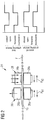
- Said conveying apparatus 24, which is illustrated in greater detail in Figure 2 , comprises a first and a second gripping device 26, 28, which can each be adjusted between an open position, in which they free the semi-finished product 16, and a closed position, in which they grip said semi-finished product 16 fast between two gripping jaws 26a, 26b, 28a, 28b.
- the gripping devices 26, 28 can also be moved through the device 10, as indicated by the arrows P K1 , P k2 in Figure 2 , in a direction of conveyance F of the reinforcing-fibre material 16 or counter to the direction of conveyance of the semi-finished product 16, between a gripping position and a releasing position.
- the operation of the conveying apparatus 24 is controlled, just like the operation of the other components of the device 10, by means of a central electronic control apparatus 30.
- a central electronic control apparatus 30 controls the operation of the two gripping devices 26, 28 in such a way that the first gripping device 26 is located in its open position and is moved, relative to the semi-finished product 16, counter to the direction of conveyance of said semi-finished product 16, out of its releasing position and into its gripping position when the second gripping device 28 is located in its closed position and is moved, in the direction of conveyance F of said semi-finished product 16, out of its gripping position and into its releasing position, together with said semi-finished product 16.
- first gripping device 26 is located in its closed position and is moved, together with the reinforcing-fibre material 16, out of its gripping position and into its releasing position in the direction of conveyance F of the semi-finished product 16, when the second gripping device 28 is located in its open position and is moved, relative to the semi-finished product 16, counter to said direction of conveyance F of said semi-finished product 16, out of its releasing position and into its gripping position.
- This oppositely directed operation of the two gripping devices 26, 28 is also illustrated in the diagrammatic chart in Figure 2 .
- said conveying apparatus 24 may also be constructed in a manner integrated with a shaping apparatus 36 to which the reinforcing-fibre material, which has been impregnated with a curable plastic material in the impregnating apparatus 22, is fed by means of said conveying apparatus 24.
- the shaping apparatus 36 the reinforcing-fibre material 16 impregnated with a curable plastic material is brought into a desired shape, as will be explained in still greater detail below.
- the device 10 may also comprise a pre-heating apparatus (not shown in Figure 1 ) which serves to pre-heat the semi-finished product 16 impregnated with a plastic material, before it is fed to the shaping apparatus 36.
- the operation of the pre-heating device is preferably controlled in such a way that the viscosity of an impregnating material consisting of a curable plastic material is increased, but there are still no substantial cross-linking reactions taking place in said curable plastic material.
- the pre-heating apparatus may comprise, for example, a convection-tunnel oven, a device for irradiating the reinforcing-fibre woven impregnated with a plastic material with electron beams, or an infrared radiator.
- the device 10 also comprises a curing apparatus 44 which serves to partly or completely cure the curable plastic material with which the reinforcing-fibre material is impregnated.
- the curing apparatus 44 may comprise, for example, a tunnel oven, an infrared radiator, a heating device that works inductively or a microwave-type heating device.
- the operation of the curing apparatus 44 that is to say the operation of a heating apparatus belonging to the curing apparatus 44, is preferably controlled by the control apparatus 30 in such a way that the curable plastic material with which the reinforcing-fibre material is impregnated is completely cured by the supplying of heat from the heating apparatus. If desired, however, it is also possible for only a partial curing of the plastic material to take place in the curing apparatus 44.
- Said cutting device 46 which cuts the semi-finished product 16 discharged from the curing apparatus 44 to a desired length in order to finally produce the components 12.
- Said cutting device 46 may, for example, comprise a band saw which is mounted in a movable manner, so that it can be moved, together with the semi-finished product 16 to be cut, through the device 10 in the direction of conveyance F of said semi-finished product 16, in order to produce a cut which extends perpendicularly to said direction of conveyance F.
- the cutting device 46 may also comprise a guiding and/or holding apparatus (not shown in Figure 1 ) which may be arranged upstream or downstream of the saw, referred to the direction of conveyance F of the semi-finished product 16, and may serve to avoid undesired displacements of said semi-finished product or vibrations in said semi-finished product 16.
- the position of the guiding and/or holding apparatus may be controlled by means of a control apparatus 30 in dependence upon a varying shape of the semi-finished product 16 which is to be cut.
- the conveying apparatus 24 may also comprise two mutually opposed conveyor belts or, as represented in Figure 3 , a toothed-rack drive with two mutually opposed toothed racks 32, 34.
- Said toothed racks 32, 34 can be adjusted, in a manner similar to the gripping devices 26, 28 of the conveying apparatus 24 shown in Figure 2 , between an open position, in which they are not in contact with one another, and an engaging position, in which they are in engagement with one another.
- a first toothed rack 32 can also be moved, as indicated by the arrow P z in Figure 3 , through the device 10 in a direction of conveyance F of the reinforcing-fibre material 16 or counter to said direction of conveyance F of said reinforcing-fibre material 16, between an engaging position and a releasing position.
- the operation of the toothed-rack drive takes place as has been described above with regard to the gripping devices 26, 28 of the conveying apparatus 24 shown in Figure 2 .
- FIGs 4 and 5 show various embodiments of a shaping apparatus 36 which may be used in the device 10.
- the shaping apparatus 36 illustrated in Figures 4a and b comprises a shaping tool 48 which has a first shaping-tool element 48a and also a second shaping-tool element 48b which is located opposite said first shaping-tool element 48a.
- the two shaping-tool elements 48a, 48b each consist of an elastically deformable material, for example PTFE, and consequently have shaping faces 49a, 49b which face towards the semi-finished product 16 and which likewise consist of an elastically deformable material.
- a press 38 which comprises a first pressing element 50 and also a second pressing element 52 which is located opposite said first pressing element 50, serves to subject the semi-finished product 16, which is arranged between the first and second shaping-tool elements 48a, 48b, to pressure in a direction perpendicular to a direction of conveyance F of said semi-finished product, see arrow P D in Figure 4a .
- the press 38 comprises a suitable driving apparatus (not shown in the Figures).
- the pressing elements 50, 52 of the press 38 are each constructed in the form of a conveyor belt.
- the conveyor belts which form the first and pressing elements 50, 52 can be moved in opposite directions and exert a gripping force on the shaping tool 48 arranged between said conveyor belts, such that said shaping tool 48 can be moved in the direction of conveyance F of the semi-finished product 16 or counter to said direction of conveyance F of said semi-finished product 16 as a result of the conveying movement of the conveyor belts.
- the first pressing element 50 comprises a number of rollers 54 which are arranged one behind another in the direction of conveyance F of the semi-finished product 16.
- the second pressing element 50 likewise comprises a number of rollers 56 which are arranged one behind another in the direction of conveyance F of the semi-finished product 16, said rollers 54, 56 of the pressing elements 50, 52 being positioned opposite one another in each case.
- the rollers 54, 56 can be displaced, in a direction perpendicular to the direction of conveyance F of the semi-finished product 16, in the direction of an arrow R v in Figure 4b , and thereby form movable mounting elements for the first and second pressing elements 50, 52.
- the rollers 54 of the first pressing element 50 can be displaced, by means of an active driving apparatus (not shown in the Figures) which is constructed, for example, in the form of a hydraulic apparatus, in a direction perpendicular to the direction of conveyance F of the semi-finished product 16, that is to say in the direction of the arrow R v in Figure 4b .
- the movably mounted rollers 56 of the second pressing element 52 are entrained when a movement of the rollers 54 of the first shaping-tool element 50 occurs, and are likewise displaced in a direction perpendicular to the direction of conveyance F of the semi-finished product 16, that is to say in the direction of the arrow R v in Figure 4b .
- Axes of rotation R A of the rollers 54 of the first pressing element 50 can also be actively tilted by an angle of, for example, 10°, relative to the direction of conveyance F of the semi-finished product 16, by means of the active driving apparatus, while the rollers 56 of the second pressing element 52 once again follow this tilting movement passively.
- a first pressing face 58 belonging to the first pressing element 50 and facing towards the semi-finished product 16 to be curved temporarily in the direction of conveyance F of said semi-finished product 16, and also to be curved, that is to say twisted, with regard to the direction of the pressing force applied to said semi-finished product.
- a second pressing face 60 which is constructed on the second pressing element 52 and faces towards the semi-finished product 16, assumes a corresponding curved and twisted shape.
- This deformation of the pressing faces 58, 60 of the pressing elements 50, 52 is transferred, because the shaping-tool elements 48, 50 are configured from an elastically deformable material, to said shaping-tool elements 48, 50, so that those shaping faces 49a, 49b of the shaping-tool elements 48a, 48b which face towards the semi-finished product 16 are likewise temporarily curved in the direction of conveyance F of said semi-finished product 16 and also curved, that is to say twisted, with regard to the direction of the pressing force which is applied to said semi-finished product.
- This shape of the shaping faces 49a, 49b of the shaping-tool elements 48a, 48b is then accordingly transferred to the semi-finished product 16.
- the shaping tool 48 also comprises a heating apparatus 66 which may be designed, for example, as electric resistance heating and which serves to heat the semi-finished product 16 arranged between the shaping-tool elements 50, 52, at least in certain sections.
- a heating apparatus 66 which may be designed, for example, as electric resistance heating and which serves to heat the semi-finished product 16 arranged between the shaping-tool elements 50, 52, at least in certain sections.
- the heating apparatus 66 may also be used for curing, at least partly or else completely, the plastic material contained in the semi-finished product 16.
- the first shaping-tool element 48a of the shaping tool 48 consists of a rigid material
- the second shaping-tool element 48b consists of an elastically deformable material.
- the first shaping-tool element 48a may, for example, consist of metal, such as, for example, steel or aluminium or an aluminium alloy.
- the second shaping-tool element 48b which consists of an elastically deformable material, may, for example, be produced from an elastomer material or be formed by a flexible container which is filled, for example, with a granular material or a fluid.
- the shape of the shaping face 49b of the second shaping-tool element 48b that consists of an elastically deformable material can then be adapted, as shown in Figure 5 , to the curved or twisted shape of the shaping face 49a of the first shaping-tool element 48 that consists of a rigid material, when the semi-finished product 16 arranged between the shaping-tool elements 48a, 48b is subjected to pressure by means of a press, of which no further details are illustrated.
- the shaping face 49a of the shaping-tool element 48a which face consists of a rigid material, has a first section 49a' which differs from a second section 49a" of said shaping face 49a with regard to a curvature in the direction of conveyance F of the semi-finished product 16 through the shaping tool 48.
- the first section 49a' of the shaping face 49a is curved in the direction of conveyance F of the semi-finished product 16, whereas the second section 49a" of said shaping face 49a has no curvature.
- the shaping-tool element 48a having the shaping face 49a that consists of a rigid material and the shaping-tool element 48b having the shaping face 49b that consists of an elastically deformable material can be moved, relative to one another, in order to bring different sections of the shaping-tool element 48a, that is to say the different sections 49a', 49a" of the shaping face 49a of said shaping-tool element 48a, into contact, as required, with the semi-finished product 16 which is to be formed.
- the operation of the shaping tool 48 is controlled in such a way that the shaping-tool elements 48a, 48b are controlled into a closed position in order to subject a first section of the semi-finished product 16, which first section is arranged between the shaping-tool elements 48a, 48b, to pressure.
- the control apparatus 30 also controls the operation of the shaping tool 48 in such a way that the shaping-tool elements 48a, 48b are moved, together with the first section of the semi-finished product 16, in the direction of conveyance F of said semi-finished product 16, as long as the shaping-tool elements 48a, 48b are subjecting said first section of the semi-finished product 16 to pressure.
- the shaping-tool elements 48a, 48b are mounted so as to be movable along a guiding apparatus, which is not shown. Finally, the shaping-tool elements 48a, 48b are guided by the control apparatus 30 into an open position and are moved, relative to the first section of the semi-finished product 16, counter to the direction of conveyance F of said semi-finished product 16 until said shaping-tool elements 48a, 48b are arranged in a position in which they can be controlled into a closed position again, in order to subject a second section of the semi-finished product 16, which second section is arranged behind the first section of said semi-finished product 16, referred to the direction of conveyance of said semi-finished product 16, to pressure.
- a shaping tool 48 which is configured in this way may also serve as part of a conveying apparatus 24.
- the shaping tool 48 then forms one of the gripping devices 26, 28 of a conveying apparatus 24, which has been described above and downstream of which, or upstream of which, the other gripping device 28, 26 is incorporated.
- the shaping tool 48 that forms one gripping device 26, 28, and the other gripping device 28, 26 can then be operated, as described above, in order to convey the semi-finished product 16 through the device 10.
- control apparatus 30 causes, if necessary, a movement of the shaping-tool elements 48a, 48b relative to one another, when said shaping-tool elements 48a, 48b are located in their open position, in order to bring the different sections of the shaping-tool element 48a into contact with the semi-finished product 16 which is to be formed.
- This is illustrated in Figure 5 , in which, in the first representation of the shaping apparatus 36 at the top left, a left-hand end of the shaping-tool element 48a is in contact with the semi-finished product 16 which is to be formed, while in the other representations, sections of the shaping-tool element 48a for forming the semi-finished product 16 which are located further to the right are used in order to shape said semi-finished product differently in certain sections.
- the shaping tools 48 shown in Figures 4 and 5 may comprise a plastic-feeding apparatus 70 which is adapted to impregnate the semi-finished product 16 arranged between the shaping-tool elements 48a, 48b with a plastic material, see Figure 6 .
- Said plastic-feeding apparatus 70 comprises a plurality of injection ducts 72 which are routed through the shaping-tool elements 48a, 48b and through which plastic material can be conducted to the semi-finished product 16.
- the pressurising operation within the shaping tool 48 may be used for forcing air which is enclosed in a dry reinforcing-fibre woven, out of said woven, and replacing said air by a plastic material which is conducted through the injection ducts 72 into the reinforcing-fibre woven before said woven is subjected to pressure.
- the semi-finished product 16 containing reinforcing fibres can be provided, in a continuous process, with a complex curved or twisted shape, for example in order to manufacture a structural component 12 for an aircraft, which component is shown in Figure 7 .
- the shaping apparatus 36 may also comprise an fixing apparatus which is adapted to fix the shaping tool in a form-locking manner, at least in certain operating phases of said shaping tool.
- Said fixing apparatus may, for example, comprise a housing consisting of a rigid material for receiving a shaping-tool element 48a, 48b which consists of an elastically deformable material.
- Said fixing apparatus may also comprise a toothed-rack drive which is illustrated in Figures 3a to c and which may then fulfil the double function of, on the one hand, moving the shaping tool relative to the semi-finished product which is conveyed through said tool, and on the other hand, fixing the shaping-tool elements 48a, 48b in a form-locking manner until they have sufficient dimensional stability.
Landscapes
- Engineering & Computer Science (AREA)
- Mechanical Engineering (AREA)
- Chemical & Material Sciences (AREA)
- Composite Materials (AREA)
- Manufacturing & Machinery (AREA)
- Casting Or Compression Moulding Of Plastics Or The Like (AREA)
- Moulding By Coating Moulds (AREA)
- Moulds For Moulding Plastics Or The Like (AREA)
Applications Claiming Priority (2)
| Application Number | Priority Date | Filing Date | Title |
|---|---|---|---|
| DE102013226739.8A DE102013226739A1 (de) | 2013-12-19 | 2013-12-19 | Formwerkzeug, Formgebungseinrichtung und Verfahren zum Verformen eines Verstärkungsfasern enthaltenden Halbzeugs |
| PCT/EP2014/078139 WO2015091600A1 (en) | 2013-12-19 | 2014-12-17 | Shaping tool, shaping apparatus and method of forming a semi-finished product containing reinforcing fibres |
Publications (2)
| Publication Number | Publication Date |
|---|---|
| EP3083225A1 EP3083225A1 (en) | 2016-10-26 |
| EP3083225B1 true EP3083225B1 (en) | 2020-03-25 |
Family
ID=52339099
Family Applications (1)
| Application Number | Title | Priority Date | Filing Date |
|---|---|---|---|
| EP14825125.9A Active EP3083225B1 (en) | 2013-12-19 | 2014-12-17 | Shaping tool, shaping apparatus and method of forming a semi-finished product containing reinforcing fibres |
Country Status (7)
| Country | Link |
|---|---|
| US (1) | US10703054B2 (zh) |
| EP (1) | EP3083225B1 (zh) |
| JP (1) | JP6453889B2 (zh) |
| CN (1) | CN105829090B (zh) |
| CA (1) | CA2931594A1 (zh) |
| DE (1) | DE102013226739A1 (zh) |
| WO (1) | WO2015091600A1 (zh) |
Families Citing this family (11)
| Publication number | Priority date | Publication date | Assignee | Title |
|---|---|---|---|---|
| DE102013226753A1 (de) * | 2013-12-19 | 2015-06-25 | Airbus Operations Gmbh | Vorrichtung und Verfahren zur kontinuierlichen Fertigung von Strukturbauteilen aus faserverstärkten Verbundmaterialien sowie Formwerkzeugset |
| US10913222B2 (en) | 2017-06-02 | 2021-02-09 | Jamco Corporation | Method for producing composite material component and device for producing composite material component |
| DE102018203360B4 (de) * | 2018-03-07 | 2021-12-30 | Volkswagen Aktiengesellschaft | Temperiervorrichtung für und eine Organobandmaterialanlage zur Herstellung von flächigen Faserverbundhalbzeugen, sowie ein entsprechendes Herstellungsverfahren |
| US11738530B2 (en) * | 2018-03-22 | 2023-08-29 | General Electric Company | Methods for manufacturing wind turbine rotor blade components |
| JP7324344B2 (ja) * | 2018-05-31 | 2023-08-09 | 川崎重工業株式会社 | 複合材料構造物の製造方法 |
| ES2880625T3 (es) * | 2018-09-11 | 2021-11-25 | Airbus Operations Sl | Métodos para la fabricación de larguerillos curvos en omega y larguerillos en forma de Z de material compuesto y para la fabricación de un panel rigidizado de material compuesto con curvatura |
| CN109435277B (zh) * | 2018-12-07 | 2024-02-20 | 中南大学 | 一种树脂基复合材料的加热固化装置 |
| DE102019100207A1 (de) * | 2019-01-07 | 2020-07-09 | Bayerische Motoren Werke Aktiengesellschaft | Verfahren und Vorrichtung zum Herstellen eines Profilbauteiles aus einem Faserverbundkunststoff |
| DE102019120378A1 (de) * | 2019-07-29 | 2021-02-04 | Airbus Operations Gmbh | Verfahren zum Herstellen eines Bauteils aus thermoplastischem Faserverbundwerkstoff und durch dieses Verfahren erhältliche Bauteile |
| CN111203996B (zh) * | 2019-12-13 | 2022-04-19 | 中国航空工业集团公司基础技术研究院 | 一种带有弯折截面预制体的制备设备及方法 |
| WO2024029019A1 (ja) * | 2022-08-04 | 2024-02-08 | 株式会社ジャムコ | 複合材部品の製造方法、および、複合材部品製造装置 |
Family Cites Families (20)
| Publication number | Priority date | Publication date | Assignee | Title |
|---|---|---|---|---|
| US3873399A (en) * | 1973-05-09 | 1975-03-25 | Goldsworthy Eng Inc | Apparatus and method for producing elongated reinforced plastic articles |
| US3987542A (en) * | 1975-08-22 | 1976-10-26 | Visco Luigi P | Scissors |
| DK92684D0 (da) * | 1983-04-20 | 1984-02-23 | Itt | Profil eller konstruktionselement af et armeret kompositmateriale samt maskine og fremgangsmade til fremstilling heraf |
| US5102609A (en) * | 1986-02-03 | 1992-04-07 | The Board Of Trustees Of The Leland Stanford Junior University | Process for forming fiber composite materials |
| JPS63278811A (ja) * | 1987-05-09 | 1988-11-16 | Mitsubishi Rayon Eng Co Ltd | 連続加圧装置 |
| JPH0569450A (ja) * | 1991-03-12 | 1993-03-23 | Takeda Chem Ind Ltd | 繊維強化樹脂材の成形方法および成形装置 |
| DE69225733T2 (de) * | 1991-03-12 | 1998-10-01 | Takeda Chemical Industries Ltd | Formverfahren und -vorrichtung |
| JP3611506B2 (ja) * | 2000-05-26 | 2005-01-19 | 住友ベークライト株式会社 | 積層板の製造方法 |
| JP3742082B2 (ja) * | 2003-08-08 | 2006-02-01 | 株式会社ジャムコ | 曲率を有した繊維強化プラスチック部材の連続成形方法及び装置 |
| DE102004001078B8 (de) | 2004-01-05 | 2013-06-13 | Airbus Operations Gmbh | Flugzeugrumpf |
| JP5021315B2 (ja) | 2004-01-05 | 2012-09-05 | エアバス オペレーションズ ゲーエムベーハー | 航空機胴体 |
| EP1621323A1 (en) | 2004-07-27 | 2006-02-01 | Hexcel Composites GmbH | Continuous pultrusion process for producing high performance structural profiles |
| US8333858B2 (en) * | 2006-02-02 | 2012-12-18 | The Boeing Company | Method for fabricating curved thermoplastic composite parts |
| DE102007013902A1 (de) * | 2007-03-20 | 2008-09-25 | Universität Dortmund | Vorrichtung zum Profilbiegen |
| DE102007062111A1 (de) | 2007-12-21 | 2009-07-02 | Airbus Deutschland Gmbh | Abschirmanordnung für insbesondere elektrische Leitungen in Flugzeugen |
| DE102008011410B4 (de) * | 2008-02-27 | 2010-05-12 | Airbus Deutschland Gmbh | Pultrusionsverfahren zur Herstellung eines profilierten Preforms oder eines profilierten FVK-Bauteils, Pultrusionsanlage sowie Press-Vorrichtung zur Durchführung des Verfahrens |
| DE102008041832B4 (de) * | 2008-09-05 | 2013-03-21 | Airbus Operations Gmbh | Vorrichtung und Verfahren |
| DE102010002988B4 (de) * | 2010-03-17 | 2014-07-17 | Zf Friedrichshafen Ag | Verfahren und Vorrichtung zur kontinuierlichen Herstellung von Profilbauteilen aus Faserverbundwerkstoff |
| JP2012213982A (ja) * | 2011-04-01 | 2012-11-08 | Mitsubishi Heavy Ind Ltd | 引抜き成形品の製造装置および引抜き成形品の製造方法 |
| JP5937894B2 (ja) * | 2012-06-04 | 2016-06-22 | 株式会社ジャムコ | 複合材ストリンガーの連続プリフォーム装置 |
-
2013
- 2013-12-19 DE DE102013226739.8A patent/DE102013226739A1/de not_active Withdrawn
-
2014
- 2014-12-17 CA CA2931594A patent/CA2931594A1/en not_active Abandoned
- 2014-12-17 CN CN201480068179.2A patent/CN105829090B/zh active Active
- 2014-12-17 WO PCT/EP2014/078139 patent/WO2015091600A1/en active Application Filing
- 2014-12-17 JP JP2016541575A patent/JP6453889B2/ja active Active
- 2014-12-17 EP EP14825125.9A patent/EP3083225B1/en active Active
-
2016
- 2016-06-16 US US15/184,606 patent/US10703054B2/en active Active
Non-Patent Citations (1)
| Title |
|---|
| None * |
Also Published As
| Publication number | Publication date |
|---|---|
| JP6453889B2 (ja) | 2019-01-16 |
| DE102013226739A1 (de) | 2015-06-25 |
| WO2015091600A1 (en) | 2015-06-25 |
| JP2017501057A (ja) | 2017-01-12 |
| US10703054B2 (en) | 2020-07-07 |
| CN105829090A (zh) | 2016-08-03 |
| CN105829090B (zh) | 2018-06-08 |
| CA2931594A1 (en) | 2015-06-25 |
| EP3083225A1 (en) | 2016-10-26 |
| US20160368230A1 (en) | 2016-12-22 |
Similar Documents
| Publication | Publication Date | Title |
|---|---|---|
| EP3083225B1 (en) | Shaping tool, shaping apparatus and method of forming a semi-finished product containing reinforcing fibres | |
| US8562881B2 (en) | Fibre composite profile component and process and apparatus for continuous production | |
| EP3083177B1 (en) | Apparatus and method for continuously manufacturing components from fibre-reinforced composites | |
| EP3083174B1 (en) | Impregnating tool and method of continuously impregnating a reinforcing fibre material with a plastics material | |
| EP2941344B1 (en) | Fabrication of reinforced thermoplastic composite parts | |
| US9044905B2 (en) | Forming device for manufacturing profiled semifinished products, system with such a forming device and method for manufacturing profiled semifinished products | |
| US6592795B2 (en) | Continuous forming method and device for H-shaped FRP member | |
| RU2534245C2 (ru) | Способ и устройство для изготовления заготовок из армированного волокном синтетического материала | |
| US10913217B2 (en) | Method and device for series production of components made of a fiber-reinforced composite material | |
| RU2715662C1 (ru) | Способ и устройство для производства композитного материала | |
| KR20180073280A (ko) | 복합소재 성형장치 | |
| EP2881242B1 (en) | Continuous preform device for composite stringer | |
| CN111746005A (zh) | 变曲率连续增强塑料纤维拉挤设备及其加工方法 |
Legal Events
| Date | Code | Title | Description |
|---|---|---|---|
| PUAI | Public reference made under article 153(3) epc to a published international application that has entered the european phase |
Free format text: ORIGINAL CODE: 0009012 |
|
| 17P | Request for examination filed |
Effective date: 20160510 |
|
| AK | Designated contracting states |
Kind code of ref document: A1 Designated state(s): AL AT BE BG CH CY CZ DE DK EE ES FI FR GB GR HR HU IE IS IT LI LT LU LV MC MK MT NL NO PL PT RO RS SE SI SK SM TR |
|
| AX | Request for extension of the european patent |
Extension state: BA ME |
|
| RIN1 | Information on inventor provided before grant (corrected) |
Inventor name: GAITZSCH, ROBERT Inventor name: BACKHAUS, SASCHA Inventor name: FUERSTE, CHRISTIAN Inventor name: LENARTOWICZ, KRZYSZTOF |
|
| DAX | Request for extension of the european patent (deleted) | ||
| STAA | Information on the status of an ep patent application or granted ep patent |
Free format text: STATUS: EXAMINATION IS IN PROGRESS |
|
| 17Q | First examination report despatched |
Effective date: 20190702 |
|
| GRAP | Despatch of communication of intention to grant a patent |
Free format text: ORIGINAL CODE: EPIDOSNIGR1 |
|
| STAA | Information on the status of an ep patent application or granted ep patent |
Free format text: STATUS: GRANT OF PATENT IS INTENDED |
|
| INTG | Intention to grant announced |
Effective date: 20191021 |
|
| GRAS | Grant fee paid |
Free format text: ORIGINAL CODE: EPIDOSNIGR3 |
|
| GRAA | (expected) grant |
Free format text: ORIGINAL CODE: 0009210 |
|
| STAA | Information on the status of an ep patent application or granted ep patent |
Free format text: STATUS: THE PATENT HAS BEEN GRANTED |
|
| AK | Designated contracting states |
Kind code of ref document: B1 Designated state(s): AL AT BE BG CH CY CZ DE DK EE ES FI FR GB GR HR HU IE IS IT LI LT LU LV MC MK MT NL NO PL PT RO RS SE SI SK SM TR |
|
| REG | Reference to a national code |
Ref country code: GB Ref legal event code: FG4D |
|
| REG | Reference to a national code |
Ref country code: AT Ref legal event code: REF Ref document number: 1248092 Country of ref document: AT Kind code of ref document: T Effective date: 20200415 Ref country code: IE Ref legal event code: FG4D |
|
| REG | Reference to a national code |
Ref country code: DE Ref legal event code: R096 Ref document number: 602014062914 Country of ref document: DE |
|
| PG25 | Lapsed in a contracting state [announced via postgrant information from national office to epo] |
Ref country code: RS Free format text: LAPSE BECAUSE OF FAILURE TO SUBMIT A TRANSLATION OF THE DESCRIPTION OR TO PAY THE FEE WITHIN THE PRESCRIBED TIME-LIMIT Effective date: 20200325 Ref country code: NO Free format text: LAPSE BECAUSE OF FAILURE TO SUBMIT A TRANSLATION OF THE DESCRIPTION OR TO PAY THE FEE WITHIN THE PRESCRIBED TIME-LIMIT Effective date: 20200625 Ref country code: FI Free format text: LAPSE BECAUSE OF FAILURE TO SUBMIT A TRANSLATION OF THE DESCRIPTION OR TO PAY THE FEE WITHIN THE PRESCRIBED TIME-LIMIT Effective date: 20200325 |
|
| PG25 | Lapsed in a contracting state [announced via postgrant information from national office to epo] |
Ref country code: BG Free format text: LAPSE BECAUSE OF FAILURE TO SUBMIT A TRANSLATION OF THE DESCRIPTION OR TO PAY THE FEE WITHIN THE PRESCRIBED TIME-LIMIT Effective date: 20200625 Ref country code: GR Free format text: LAPSE BECAUSE OF FAILURE TO SUBMIT A TRANSLATION OF THE DESCRIPTION OR TO PAY THE FEE WITHIN THE PRESCRIBED TIME-LIMIT Effective date: 20200626 Ref country code: HR Free format text: LAPSE BECAUSE OF FAILURE TO SUBMIT A TRANSLATION OF THE DESCRIPTION OR TO PAY THE FEE WITHIN THE PRESCRIBED TIME-LIMIT Effective date: 20200325 Ref country code: LV Free format text: LAPSE BECAUSE OF FAILURE TO SUBMIT A TRANSLATION OF THE DESCRIPTION OR TO PAY THE FEE WITHIN THE PRESCRIBED TIME-LIMIT Effective date: 20200325 Ref country code: SE Free format text: LAPSE BECAUSE OF FAILURE TO SUBMIT A TRANSLATION OF THE DESCRIPTION OR TO PAY THE FEE WITHIN THE PRESCRIBED TIME-LIMIT Effective date: 20200325 |
|
| REG | Reference to a national code |
Ref country code: NL Ref legal event code: MP Effective date: 20200325 |
|
| REG | Reference to a national code |
Ref country code: LT Ref legal event code: MG4D |
|
| PG25 | Lapsed in a contracting state [announced via postgrant information from national office to epo] |
Ref country code: NL Free format text: LAPSE BECAUSE OF FAILURE TO SUBMIT A TRANSLATION OF THE DESCRIPTION OR TO PAY THE FEE WITHIN THE PRESCRIBED TIME-LIMIT Effective date: 20200325 |
|
| PG25 | Lapsed in a contracting state [announced via postgrant information from national office to epo] |
Ref country code: SK Free format text: LAPSE BECAUSE OF FAILURE TO SUBMIT A TRANSLATION OF THE DESCRIPTION OR TO PAY THE FEE WITHIN THE PRESCRIBED TIME-LIMIT Effective date: 20200325 Ref country code: IS Free format text: LAPSE BECAUSE OF FAILURE TO SUBMIT A TRANSLATION OF THE DESCRIPTION OR TO PAY THE FEE WITHIN THE PRESCRIBED TIME-LIMIT Effective date: 20200725 Ref country code: RO Free format text: LAPSE BECAUSE OF FAILURE TO SUBMIT A TRANSLATION OF THE DESCRIPTION OR TO PAY THE FEE WITHIN THE PRESCRIBED TIME-LIMIT Effective date: 20200325 Ref country code: CZ Free format text: LAPSE BECAUSE OF FAILURE TO SUBMIT A TRANSLATION OF THE DESCRIPTION OR TO PAY THE FEE WITHIN THE PRESCRIBED TIME-LIMIT Effective date: 20200325 Ref country code: PT Free format text: LAPSE BECAUSE OF FAILURE TO SUBMIT A TRANSLATION OF THE DESCRIPTION OR TO PAY THE FEE WITHIN THE PRESCRIBED TIME-LIMIT Effective date: 20200818 Ref country code: LT Free format text: LAPSE BECAUSE OF FAILURE TO SUBMIT A TRANSLATION OF THE DESCRIPTION OR TO PAY THE FEE WITHIN THE PRESCRIBED TIME-LIMIT Effective date: 20200325 Ref country code: SM Free format text: LAPSE BECAUSE OF FAILURE TO SUBMIT A TRANSLATION OF THE DESCRIPTION OR TO PAY THE FEE WITHIN THE PRESCRIBED TIME-LIMIT Effective date: 20200325 Ref country code: EE Free format text: LAPSE BECAUSE OF FAILURE TO SUBMIT A TRANSLATION OF THE DESCRIPTION OR TO PAY THE FEE WITHIN THE PRESCRIBED TIME-LIMIT Effective date: 20200325 |
|
| REG | Reference to a national code |
Ref country code: AT Ref legal event code: MK05 Ref document number: 1248092 Country of ref document: AT Kind code of ref document: T Effective date: 20200325 |
|
| REG | Reference to a national code |
Ref country code: DE Ref legal event code: R097 Ref document number: 602014062914 Country of ref document: DE |
|
| PG25 | Lapsed in a contracting state [announced via postgrant information from national office to epo] |
Ref country code: DK Free format text: LAPSE BECAUSE OF FAILURE TO SUBMIT A TRANSLATION OF THE DESCRIPTION OR TO PAY THE FEE WITHIN THE PRESCRIBED TIME-LIMIT Effective date: 20200325 Ref country code: IT Free format text: LAPSE BECAUSE OF FAILURE TO SUBMIT A TRANSLATION OF THE DESCRIPTION OR TO PAY THE FEE WITHIN THE PRESCRIBED TIME-LIMIT Effective date: 20200325 Ref country code: AT Free format text: LAPSE BECAUSE OF FAILURE TO SUBMIT A TRANSLATION OF THE DESCRIPTION OR TO PAY THE FEE WITHIN THE PRESCRIBED TIME-LIMIT Effective date: 20200325 Ref country code: ES Free format text: LAPSE BECAUSE OF FAILURE TO SUBMIT A TRANSLATION OF THE DESCRIPTION OR TO PAY THE FEE WITHIN THE PRESCRIBED TIME-LIMIT Effective date: 20200325 |
|
| PLBE | No opposition filed within time limit |
Free format text: ORIGINAL CODE: 0009261 |
|
| STAA | Information on the status of an ep patent application or granted ep patent |
Free format text: STATUS: NO OPPOSITION FILED WITHIN TIME LIMIT |
|
| PG25 | Lapsed in a contracting state [announced via postgrant information from national office to epo] |
Ref country code: PL Free format text: LAPSE BECAUSE OF FAILURE TO SUBMIT A TRANSLATION OF THE DESCRIPTION OR TO PAY THE FEE WITHIN THE PRESCRIBED TIME-LIMIT Effective date: 20200325 |
|
| 26N | No opposition filed |
Effective date: 20210112 |
|
| PG25 | Lapsed in a contracting state [announced via postgrant information from national office to epo] |
Ref country code: SI Free format text: LAPSE BECAUSE OF FAILURE TO SUBMIT A TRANSLATION OF THE DESCRIPTION OR TO PAY THE FEE WITHIN THE PRESCRIBED TIME-LIMIT Effective date: 20200325 |
|
| REG | Reference to a national code |
Ref country code: CH Ref legal event code: PL |
|
| PG25 | Lapsed in a contracting state [announced via postgrant information from national office to epo] |
Ref country code: MC Free format text: LAPSE BECAUSE OF FAILURE TO SUBMIT A TRANSLATION OF THE DESCRIPTION OR TO PAY THE FEE WITHIN THE PRESCRIBED TIME-LIMIT Effective date: 20200325 |
|
| REG | Reference to a national code |
Ref country code: BE Ref legal event code: MM Effective date: 20201231 |
|
| PG25 | Lapsed in a contracting state [announced via postgrant information from national office to epo] |
Ref country code: LU Free format text: LAPSE BECAUSE OF NON-PAYMENT OF DUE FEES Effective date: 20201217 Ref country code: IE Free format text: LAPSE BECAUSE OF NON-PAYMENT OF DUE FEES Effective date: 20201217 |
|
| PG25 | Lapsed in a contracting state [announced via postgrant information from national office to epo] |
Ref country code: CH Free format text: LAPSE BECAUSE OF NON-PAYMENT OF DUE FEES Effective date: 20201231 Ref country code: LI Free format text: LAPSE BECAUSE OF NON-PAYMENT OF DUE FEES Effective date: 20201231 |
|
| PG25 | Lapsed in a contracting state [announced via postgrant information from national office to epo] |
Ref country code: TR Free format text: LAPSE BECAUSE OF FAILURE TO SUBMIT A TRANSLATION OF THE DESCRIPTION OR TO PAY THE FEE WITHIN THE PRESCRIBED TIME-LIMIT Effective date: 20200325 Ref country code: MT Free format text: LAPSE BECAUSE OF FAILURE TO SUBMIT A TRANSLATION OF THE DESCRIPTION OR TO PAY THE FEE WITHIN THE PRESCRIBED TIME-LIMIT Effective date: 20200325 Ref country code: CY Free format text: LAPSE BECAUSE OF FAILURE TO SUBMIT A TRANSLATION OF THE DESCRIPTION OR TO PAY THE FEE WITHIN THE PRESCRIBED TIME-LIMIT Effective date: 20200325 |
|
| PG25 | Lapsed in a contracting state [announced via postgrant information from national office to epo] |
Ref country code: MK Free format text: LAPSE BECAUSE OF FAILURE TO SUBMIT A TRANSLATION OF THE DESCRIPTION OR TO PAY THE FEE WITHIN THE PRESCRIBED TIME-LIMIT Effective date: 20200325 Ref country code: AL Free format text: LAPSE BECAUSE OF FAILURE TO SUBMIT A TRANSLATION OF THE DESCRIPTION OR TO PAY THE FEE WITHIN THE PRESCRIBED TIME-LIMIT Effective date: 20200325 |
|
| PG25 | Lapsed in a contracting state [announced via postgrant information from national office to epo] |
Ref country code: BE Free format text: LAPSE BECAUSE OF NON-PAYMENT OF DUE FEES Effective date: 20201231 |
|
| PGFP | Annual fee paid to national office [announced via postgrant information from national office to epo] |
Ref country code: GB Payment date: 20231220 Year of fee payment: 10 |
|
| PGFP | Annual fee paid to national office [announced via postgrant information from national office to epo] |
Ref country code: FR Payment date: 20231221 Year of fee payment: 10 Ref country code: DE Payment date: 20231214 Year of fee payment: 10 |