EP3083136B1 - Exhaust device and machine tool - Google Patents
Exhaust device and machine tool Download PDFInfo
- Publication number
- EP3083136B1 EP3083136B1 EP14816210.0A EP14816210A EP3083136B1 EP 3083136 B1 EP3083136 B1 EP 3083136B1 EP 14816210 A EP14816210 A EP 14816210A EP 3083136 B1 EP3083136 B1 EP 3083136B1
- Authority
- EP
- European Patent Office
- Prior art keywords
- air
- channel
- exhaust
- workpiece
- processing area
- Prior art date
- Legal status (The legal status is an assumption and is not a legal conclusion. Google has not performed a legal analysis and makes no representation as to the accuracy of the status listed.)
- Active
Links
- 239000002245 particle Substances 0.000 claims description 44
- 238000003754 machining Methods 0.000 claims description 26
- 238000000034 method Methods 0.000 claims description 26
- 230000008569 process Effects 0.000 claims description 24
- 238000001914 filtration Methods 0.000 claims description 19
- 238000000926 separation method Methods 0.000 claims description 14
- 230000005484 gravity Effects 0.000 claims description 7
- 239000000428 dust Substances 0.000 claims description 6
- 239000002131 composite material Substances 0.000 claims description 3
- 239000007769 metal material Substances 0.000 claims description 3
- 239000004033 plastic Substances 0.000 claims description 3
- 229920003023 plastic Polymers 0.000 claims description 3
- 238000003860 storage Methods 0.000 claims description 3
- 239000002023 wood Substances 0.000 claims description 3
- 239000000835 fiber Substances 0.000 claims 1
- 239000003570 air Substances 0.000 description 93
- 238000003801 milling Methods 0.000 description 11
- 238000000605 extraction Methods 0.000 description 10
- 230000029058 respiratory gaseous exchange Effects 0.000 description 7
- 239000012080 ambient air Substances 0.000 description 4
- 238000005422 blasting Methods 0.000 description 4
- 230000000694 effects Effects 0.000 description 4
- 238000005286 illumination Methods 0.000 description 4
- 230000004888 barrier function Effects 0.000 description 3
- 230000008901 benefit Effects 0.000 description 3
- 239000004918 carbon fiber reinforced polymer Substances 0.000 description 3
- 238000001514 detection method Methods 0.000 description 3
- 238000004880 explosion Methods 0.000 description 3
- 238000004519 manufacturing process Methods 0.000 description 3
- 230000008859 change Effects 0.000 description 2
- 238000000151 deposition Methods 0.000 description 2
- 239000000463 material Substances 0.000 description 2
- 238000005299 abrasion Methods 0.000 description 1
- 230000015572 biosynthetic process Effects 0.000 description 1
- 238000007664 blowing Methods 0.000 description 1
- 239000011362 coarse particle Substances 0.000 description 1
- 238000011109 contamination Methods 0.000 description 1
- 238000001816 cooling Methods 0.000 description 1
- 230000001419 dependent effect Effects 0.000 description 1
- 230000008021 deposition Effects 0.000 description 1
- 230000008030 elimination Effects 0.000 description 1
- 238000003379 elimination reaction Methods 0.000 description 1
- 238000005538 encapsulation Methods 0.000 description 1
- 238000004134 energy conservation Methods 0.000 description 1
- 239000002657 fibrous material Substances 0.000 description 1
- 230000005855 radiation Effects 0.000 description 1
- 230000009467 reduction Effects 0.000 description 1
- 230000000241 respiratory effect Effects 0.000 description 1
Images


Classifications
-
- B—PERFORMING OPERATIONS; TRANSPORTING
- B23—MACHINE TOOLS; METAL-WORKING NOT OTHERWISE PROVIDED FOR
- B23Q—DETAILS, COMPONENTS, OR ACCESSORIES FOR MACHINE TOOLS, e.g. ARRANGEMENTS FOR COPYING OR CONTROLLING; MACHINE TOOLS IN GENERAL CHARACTERISED BY THE CONSTRUCTION OF PARTICULAR DETAILS OR COMPONENTS; COMBINATIONS OR ASSOCIATIONS OF METAL-WORKING MACHINES, NOT DIRECTED TO A PARTICULAR RESULT
- B23Q11/00—Accessories fitted to machine tools for keeping tools or parts of the machine in good working condition or for cooling work; Safety devices specially combined with or arranged in, or specially adapted for use in connection with, machine tools
- B23Q11/0042—Devices for removing chips
- B23Q11/006—Devices for removing chips by sucking and blowing simultaneously
-
- B—PERFORMING OPERATIONS; TRANSPORTING
- B08—CLEANING
- B08B—CLEANING IN GENERAL; PREVENTION OF FOULING IN GENERAL
- B08B15/00—Preventing escape of dirt or fumes from the area where they are produced; Collecting or removing dirt or fumes from that area
- B08B15/04—Preventing escape of dirt or fumes from the area where they are produced; Collecting or removing dirt or fumes from that area from a small area, e.g. a tool
Definitions
- the invention relates to a suction device for the extraction of particles such as chips or dusts from the machining area during machining or dry machining according to the preamble of claim 1, a machine tool according to the preamble of claim 13 and a method for sucking particles according to the preamble of the claim 16th
- a suction device for the extraction of particles such as chips or dusts from the machining area during machining or dry machining according to the preamble of claim 1
- a machine tool according to the preamble of claim 13 and a method for sucking particles according to the preamble of the claim 16th
- suck chips such as in the wood or composite material processing and dry machining of metallic materials.
- space- and ground-level extraction systems are used.
- a dust extractor hood for machine tools is known, which is used in the vicinity of the processing area.
- the extracted, contaminated air must conventionally be cleaned of the particles before it is released to the environment.
- a suction device according to the preamble of the appended claim 1 is known from DE 196 51 662 A1 known.
- the object of the invention is to provide a suction device or a machine tool as well as a method for suction available, which allow energy savings.
- the suction device according to the invention is used for the extraction of particles such as chips or dusts from the processing area in the machining of wood, fiber or composite materials or plastic and optionally in the dry machining of metallic materials.
- the suction device according to the invention comprises a suction channel for the removal of air together with the chips or dusts to be sucked out of the processing area.
- a supply channel for supplying air is provided in the processing area, wherein the suction channel and the feed channel are coupled together so that at least a portion of the suctioned through the suction air into the supply channel for returning the air passed into the processing area becomes.
- the feed channel is designed to directly irradiate a tool or workpiece in the processing area. For illuminating the machining tool or the workpiece to be machined process air is thus used, which has been previously sucked through the suction. This process air then comes from the processing area and is regularly enriched with particles from the processing.
- the targeted irradiation of the tool or workpiece with process air can prevent the particles formed during machining from depositing at undesired points and thus lead to contamination of the machined workpiece or even hinder this during the machining process.
- an air supply for illuminating the tool or workpiece and an extraction of the process air from the processing area are advantageously carried out, wherein the tool or the workpiece is irradiated directly, an effective removal of the particles in the processing area.
- the quality of the machining process can be increased significantly.
- the illumination of the workpiece or tool can basically contribute to the cooling during machining process.
- the measure that the suction channel and feed channel are coupled together, whereby at least a portion of the extracted air is then used for direct illumination of the tool or the workpiece, can make a significant contribution to energy conservation.
- the process air, which is to be sucked off anyway, is used once again to illuminate the processing area itself.
- a separate compressed air supply for lighting up in the processing area is therefore basically not necessary.
- the air used to illuminate a tool or workpiece does not have such high requirements as are used for the breathing air outside the processing area. It is therefore not necessary to filter and process the process air used for illuminating in the processing area such that it equals the purity of breathing air outside the processing area.
- the process air is guided in a circuit that is formed substantially closed and the airborne particles that come from the machining process, not with a Operator via the breathing air in contact.
- the type of particles produced during processing depends, among other things, on the machining process itself.
- a pre-separator for filtering in particular for coarse filtration is provided. This pre-separator filters the air extracted via the suction channel. By using such a pre-separator can also be ensured that the processing process itself is not affected by the particles contained in the air when illuminated.
- the pre-separator can be designed, for example, as a fly-power separator, as a gravity separator or as a deduster.
- a fly-power separator By means of centrifugal force separators and gravitational separators, in particular coarse, mass-rich particles can be separated out.
- a deduster is particularly advantageous if, for example actually finer particles must be filtered out, since otherwise, for example, the lower explosion limit can be exceeded.
- the suction channel comprises a branch which branches off into at least two separation channels connected in parallel. So it can be created optional ways to guide the process air.
- At least one of the separation channels may comprise at least one pre-separator for coarse filtering of the air extracted via the suction channel. If, for example, different types of pre-separators or even (in at least one channel) no pre-separator at all are provided in the parallel-connected separation channels, advantageously different particle sizes can be filtered out.
- the suction device according to this embodiment can therefore account for different machining processes, for example on different workpieces.
- a switchover between the separation channels can advantageously be provided by means of a switch in a development of the invention, so that the dusts are then filtered out into a separation channel via a deduster. If, in turn, mainly rough shavings occur during processing, they can be filtered out, for example, by means of a gravity separator as a pre-separator. For this purpose can be switched to a corresponding separation channel with matching Vorseparator.
- a portion of the extracted process air is discharged via a branch channel, to this pass through a fine filter device fine filtering allow. For example, 5% to 10% more air can be sucked off than blown in for irradiation.
- the actual cycle which includes the return of the extracted process air, thereby moves about 90% to 95% of the extracted air.
- the branch leading to the fine filter system is provided. Part of the contaminated process air is therefore filtered fine and can then be released to the environment.
- the process air routed to the circuit is usually subject to the stipulation that the lower explosion limit is not exceeded.
- the branch channel is connected downstream of the pre-separator, so that the air supplied to the fine filter device is prefiltered already in a first filter stage in the sense of coarse filtering.
- Feed channel and suction channel can basically be formed or arranged in different ways depending on the nature of the machining process.
- the suction channel is designed as a suction hood.
- a suction hood usually has the advantage that it has at least a partial encapsulation of the processing area allows, whereby advantageously a majority of the resulting particles in the processing of the suction is detected and removed.
- a suction hood usually allows a defined removal of the particle-enriched air, which takes place away from the workpiece to be machined. This means that the contact between particle and workpiece can be significantly reduced.
- the suction hood can almost completely enclose the machining area (with the exception of the area adjacent to the workpiece).
- the supply duct can advantageously be integrated in the extraction hood. Suction and supply area then form a largely closed unit, so that the resulting particles can hardly get out of this area and can be sucked off to a very large extent.
- a fully enclosing suction hood can also interfere with the tool change.
- exhaust nozzles and / or supply air nozzles can be flexibly positionable, for example via joints on the respective ducts.
- a flow device for generating the air flow may be provided, in particular for the production of compressed air.
- a blower can be used, with which the air is sucked in and finally supplied for illumination.
- a constriction of the feed channel can be used to increase the flow velocity of the jet air and thus achieve a greater pressure effect when blasting.
- an additional blower device is provided, with the pressure effect is increased again when you shine.
- a machine tool according to the invention for machining a workpiece with a machining area for supporting or machining the workpiece is characterized in that a suction device according to the invention or an embodiment of the invention is present. The processing area is then the area in which the workpiece is stored or processed.
- the area of storage of the workpiece is significantly greater than, for example, the processing area in connection with the proposed suction device is of particular importance in which area the particles produced during processing reach and are suitably sucked off.
- the advantages of the suction device according to the invention can be utilized.
- the suction channel can be integrated internally into the tool of a machine tool. The extraction is then carried out directly at the place where the machining of the workpiece is actually carried out and where then arise on the particles. This can reduce the effect that the particles spread in the ambient air in the processing area; they are therefore removed immediately after their formation. This measure allows a similar effect, namely an extraction with increased efficiency, wherein advantageously the resulting particles are scattered less in space.
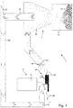
- FIG. 1 2 shows a drive spindle 3 (in a housing) for driving a tool, in this case a milling cutter 5 clamped in the chuck 4.
- a workpiece 7 to be machined is mounted on a workpiece table 6 clamped.
- the milling cutter 5 generates particles 8, in particular chips.
- the suction channel has an in FIG. 1 not shown blower device. From the processing area, immediately in the vicinity of the machining tool 5 and the workpiece 7 air is sucked in, which also contains the accrued particles 8 accordingly. The direction of the air flow is indicated by the arrows 10. Air, including the particles 8 is transported on via the suction and passes into a pre-separator 11th
- the pre-separator 11 is a gravitational separator.
- the air flow with the particles enters a funnel 12 and is guided substantially down the side walls thereof.
- the funnel 12 opens into a container 13, which closes tightly with the funnel 12.
- the air flow is thus carried away substantially over the funnel mouth and the container 13, so that the particles 8 emerge from the stream and fall down into the container 13 as a result of gravity.
- the conduit is continued via a pipe 14.
- the line 14 finally has a branch 15, and the main flow is continued via the line 16, so that the air is finally passed into the feed channel 17, with which the cutter 5 is irradiated.
- the air is thus passed from the channel 14 partially into the channel 16 and 17, respectively.
- the remaining air enters the branch 15, which eventually leads into a fine filter device (in FIG. 1 not shown).
- the branched off via the channel 15 stream comprises about 5% to 10% of the total extracted air flow over the channel 9 is withdrawn.
- the remaining 90% to 95% of the air is injected via the channel 16 under pressure into the processing area.
- the workpiece 7 and the tool 5 are illuminated directly with the air.
- This suction device 1 allows a much higher detection rate of the particles 8 than is otherwise possible in conventional machines, in particular, the suction device according to the invention offers the possibility of energy saving compared to conventional suction devices.
- blowing blowers or compressed air lances have been used in the prior art to date, for example, which can agitate the particles;
- these conventional measures have the disadvantage that they work very energy consuming.
- the circuit of extracted and recirculated air, which is used for irradiation in the processing area is formed closed. Even if strict regulations exist that filtered or finely filtered air can not be used as breathing air in the production hall, a corresponding suction device according to the invention can still be used, especially since the branched off for fine filtration air can be led to the outside, while the vast majority of at least 95% is enclosed in a closed circuit and is not used as breathing air.
- the suction device according to the invention because, as already stated, smaller amounts of air must be finely filtered. On the one hand, this results in a much lower intrinsic resistance of the line in which the filter device is arranged. On the other hand, a line with pre-separator has a significantly lower air resistance than a line in which a fine filter system is arranged. Thus, the energy requirement is lowered accordingly. Overall, it can be achieved that much less fresh air is contaminated, since on the one hand less air is sucked and on the other hand, the majority of the air used is already embedded as process air in a circuit anyway.
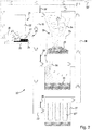
- FIG. 2 shows a suction device 20 with a machine tool 21, with a spindle housing 22, a chuck 23 and a cutter 24.
- a workpiece 26 is supported, which is processed by the cutter 24.
- the device comprises a suction line 27 and a feed line 28.
- the tool 24 or the workpiece 26 are irradiated directly at the corresponding point with air from the feed channel 28.
- the air, plus a small amount of air from the vicinity of the processing area is sucked through the channel 27. Simultaneously with the air, particles 29 produced during processing are sucked in.
- Branch 30 leads to a gravity pre-separator 33, which also has a funnel 34 and a connected thereto Container 35 has.
- the pre-separator 33 is a gravity separator. The particles 29 can not follow the movement which the accelerated air mass passes through the funnel 34 and thus fall into the container 35.
- the branch 31 leads to a further separator, in which also a barrier is used on which the incoming air streams bounce.
- a barrier is used on which the incoming air streams bounce.
- the further branch 32 leads as Vorseparator to a finger-like filter structure 37 ', which is arranged in a container 37.
- This pre-separator 37 is designed as a deduster. The sucked air there bounces first on a wall, is forwarded until it finally enters the channel, which is continued within the suction device or machine tool. Via the corresponding channel 38, the majority of the air with the corresponding particles passes back into the feed channel and is used to illuminate workpieces / tools. Via the branch 38 ', a small percentage of the air passes for fine filtering.
- shut-off plates or switches 39 are provided with which the respective channels 30, 31 and 32 can be closed individually.
- the channels 31 and 32 can be shut off, so that a device similar to that FIG. 1 known device is present.
- individual pre-separators can be "deactivated” because their access is blocked. If, for example, only the channel 30 is open, then a device similar to that is out FIG. 1 in front.
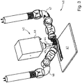
- FIG. 3 shows a processing area 40 in which a workpiece 41 is processed by a machine tool 42, namely a milling machine 42.
- the cutter consists of a spindle housing 43, a chuck 44 and a cutter 45.
- a feed channel for direct illumination of the processing area namely the channel 46.
- This channel 46 has multiple joints and thus can be set arbitrarily.
- the discharge channel 47. Both are placed with their respective openings in the vicinity of the cutter 45 and can thus provide directly for a corresponding material removal. It is also conceivable to use a suction hood, which is mounted directly above the corresponding tool.
- FIG. 4 is also the machine tool 50 with the spindle housing 51, the chuck 52 and the cutter 53 shown.
- a hood 54 is arranged to the chuck 52 and the cutter 53.
- the hood 54 is usually made of plastic and has a connection to the feed channel 57 and the exhaust air duct 56, wherein the irradiation takes place through the feed channel 57. Particles that originate from the machining process are sucked in via the suction channel and transported on.
- the milling cutter 53 processes the workpiece 55.
- the particles formed during machining remain largely within the milling hood 54 in this arrangement.
- Such a milling hood 54 thus provides very good protection so that the corresponding particles can not escape to the outside.
- the hood can therefore be removed removed or replaced.
- a tool-based extraction has basically prevailed especially in the CFRP processing of board materials (CFRP: abbreviation for carbon fiber reinforced plastic).
- FIG. 5 again shows a processing area 60 with a Machine tool 61, consisting of a spindle housing 62, a chuck 63 and a cutter 64.
- a feed channel 65 and a suction channel 66 are arranged accordingly. These channels 65 can be aligned with the router 64, but do not have individual joints. The cutter then processes the workpiece 67.
- All embodiments of the invention have in common that a feed channel is provided for supplying air into the processing area and the suction channel and the feed channel are coupled together so that at least a portion of the suctioned through the suction air into the feed channel for returning the air into the processing area becomes.
- the feed channel serves in particular to directly irradiate the workpiece or tool. This measure allows a significant energy saving and a better detection / elimination of chips / dusts.
Description
Die Erfindung betrifft eine Absaugvorrichtung zur Absaugung von Partikeln wie Spänen beziehungsweise Stäuben aus dem Bearbeitungsbereich bei der Zerspanung oder bei der Trockenbearbeitung nach dem Oberbegriff des Anspruchs 1, eine Werkzeugmaschine nach dem Oberbegriff des Anspruchs 13 sowie ein Verfahren zum Absaugen von Partikeln nach dem Oberbegriff des Anspruchs 16.
Aus dem Stand der Technik ist bekannt, Späne, etwa bei der Holz- oder Verbundwerkstoffverarbeitung sowie bei der Trockenbearbeitung von metallischen Werkstoffen abzusaugen. Dabei werden hauptsächlich raum- und bodennahe Absauganlagen eingesetzt. Aus der
From the prior art is known to suck chips, such as in the wood or composite material processing and dry machining of metallic materials. In this case, mainly space- and ground-level extraction systems are used. From the
Die Aufgabe wird, ausgehend von einer Absaugvorrichtung und einer Werkzeugmaschine durch die kennzeichnenden Merkmale der Ansprüche 1 und 10 gelöst. Durch die in den abhängigen Ansprüchen genannten Maßnahmen sind vorteilhafte Ausführungen und Weiterbildung der Erfindung möglich.
Dementsprechend dient die erfindungsgemäße Absaugvorrichtung zur Absaugung von Partikeln wie Spänen beziehungsweise Stäuben aus dem Bearbeitungsbereich bei der Zerspanung von Holz-, Faser- oder Verbundwerkstoffen oder von Kunststoff sowie gegebenenfalls bei der Trockenbearbeitung von metallischen Werkstoffen.
Die erfindungsgemäße Absaugvorrichtung umfasst einen Absaugkanal zur Abführung von Luft zusammen mit dem abzusaugenden Spänen beziehungsweise Stäuben aus dem Bearbeitungsbereich. Sie zeichnet sich dadurch aus, dass ein Zuführkanal zur Zuführung von Luft in den Bearbeitungsbereich vorgesehen ist, wobei der Absaugkanal und der Zuführkanal miteinander gekoppelt sind, sodass wenigstens ein Teil der über den Absaugkanal abgesaugten Luft in den Zuführkanal zur Rückführung der Luft in den Bearbeitungsbereich geleitet wird. Ferner ist der Zuführkanal dazu ausgebildet, ein Werkzeug beziehungsweise Werkstück im Bearbeitungsbereich unmittelbar anzustrahlen. Zum Anstrahlen des bearbeitenden Werkzeugs beziehungsweise des zu bearbeitenden Werkstücks wird demnach Prozessluft verwendet, die zuvor über den Absaugkanal abgesaugt wurde. Diese Prozessluft stammt sodann aus dem Bearbeitungsbereich und ist regelmäßig mit Partikel aus der Bearbeitung angereichert.The object is achieved on the basis of a suction device and a machine tool by the characterizing features of claims 1 and 10. The measures mentioned in the dependent claims advantageous embodiments and development of the invention are possible.
Accordingly, the suction device according to the invention is used for the extraction of particles such as chips or dusts from the processing area in the machining of wood, fiber or composite materials or plastic and optionally in the dry machining of metallic materials.
The suction device according to the invention comprises a suction channel for the removal of air together with the chips or dusts to be sucked out of the processing area. It is characterized in that a supply channel for supplying air is provided in the processing area, wherein the suction channel and the feed channel are coupled together so that at least a portion of the suctioned through the suction air into the supply channel for returning the air passed into the processing area becomes. Furthermore, the feed channel is designed to directly irradiate a tool or workpiece in the processing area. For illuminating the machining tool or the workpiece to be machined process air is thus used, which has been previously sucked through the suction. This process air then comes from the processing area and is regularly enriched with particles from the processing.
Durch das gezielte Anstrahlen des Werkzeugs oder Werkstücks mit Prozessluft kann verhindert werden, dass sich die bei der Bearbeitung entstehenden Partikel an ungewollten Stellen ablagern und somit zu Verunreinigungen des bearbeitenden Werkstücks führen oder sogar während des Bearbeitungsprozesses diesen behindern. Dadurch also, dass in vorteilhafter Weise eine Luftzuführung zum Anstrahlen des Werkzeugs beziehungsweise Werkstücks und eine Absaugung der Prozessluft aus dem Bearbeitungsbereich vorgenommen werden, wobei das Werkzeug oder das Werkstück unmittelbar angestrahlt wird, kann eine effektive Beseitigung der Partikel im Bearbeitungsbereich erfolgen. Die Qualität des Bearbeitungsprozesses kann dadurch sehr deutlich erhöht werden. Zudem kann auch die Anstrahlung des Werkstücks oder Werkzeugs grundsätzlich zur Kühlung bei Bearbeitungsprozess beitragen.The targeted irradiation of the tool or workpiece with process air can prevent the particles formed during machining from depositing at undesired points and thus lead to contamination of the machined workpiece or even hinder this during the machining process. As a result, that an air supply for illuminating the tool or workpiece and an extraction of the process air from the processing area are advantageously carried out, wherein the tool or the workpiece is irradiated directly, an effective removal of the particles in the processing area. The quality of the machining process can be increased significantly. In addition, the illumination of the workpiece or tool can basically contribute to the cooling during machining process.
Die Maßnahme, dass Absaugkanal und Zuführkanal miteinander gekoppelt sind, wodurch wenigstens ein Teil der abgesaugten Luft sodann zur unmittelbaren Anstrahlung des Werkzeugs oder des Werkstücks verwendet wird, kann ein deutlicher Beitrag zur Energieeinsparung erfolgen. Die ohnehin abzusaugende Prozessluft wird noch einmal zum Anstrahlen im Bearbeitungsbereich selbst verwendet. Eine gesonderte Druckluftversorgung zum Anstrahlen im Bearbeitungsbereich ist also grundsätzlich nicht notwendig.The measure that the suction channel and feed channel are coupled together, whereby at least a portion of the extracted air is then used for direct illumination of the tool or the workpiece, can make a significant contribution to energy conservation. The process air, which is to be sucked off anyway, is used once again to illuminate the processing area itself. A separate compressed air supply for lighting up in the processing area is therefore basically not necessary.
Zudem ist zu beachten, dass für die zum Anstrahlen eines Werkzeugs oder Werkstücks verwendete Luft keine derart hohen Anforderungen bestehen, wie sie für die Atemluft außerhalb des Bearbeitungsbereiches angesetzt werden. Es ist daher nicht t notwendig, die zum Anstrahlen im Bearbeitungsbereich verwendete Prozessluft derart zu filtern und aufzubereiten, dass sie der Reinheit von Atemluft außerhalb des Bearbeitungsbereichs gleichkommt.In addition, it should be noted that the air used to illuminate a tool or workpiece does not have such high requirements as are used for the breathing air outside the processing area. It is therefore not necessary to filter and process the process air used for illuminating in the processing area such that it equals the purity of breathing air outside the processing area.
Ferner wird ermöglicht, dass die Prozessluft in einem Kreislauf geführt wird, der im Wesentlichen geschlossen ausgebildet ist und die in der Luft befindlichen Partikel, die aus dem Bearbeitungsprozess stammen, nicht mit einer Bedienperson über die Atemluft in Kontakt treten.
Die Art der bei der Bearbeitung anfallenden Partikel hängt unter anderem vom Bearbeitungsprozess selbst ab. Um in vorteilhafter Weise sicherzustellen, dass die zum Anstrahlen verwendete Prozessluft nicht etwa aufgrund hoher Staubkonzentration die untere Explosionsgrenze überschreitet, ist ein Vorseparator zur Filterung, insbesondere zur Grobfilterung vorgesehen. Dieser Vorseparator filtert die über den Absaugkanal abgesaugt Luft. Durch die Verwendung eines derartigen Vorseparators kann zudem sichergestellt werden, dass der Bearbeitungsprozess selbst durch die in der Luft enthaltenen Partikel beim Anstrahlen nicht beeinträchtigt wird. Zum Beispiel könnten andernfalls grobe Partikel, die beim Anstrahlen des Werkzeugs oder Werkstücks mit Druck hohe Geschwindigkeiten aufnehmen können, einen Abtrieb verursachen und somit Werkzeug oder Werkstück beschädigen. Regelmäßig ist in vorteilhafterweise nur eine Grobfilterung notwendig, weil die zum Anstrahlen verwendete Prozessluft nicht den Reinheitsgrad wie zum Beispiel Atemluft aufweisen muss.
Zum einen können dadurch Kosten eingespart werden, da eine Anlage zur Grobfilterung regelmäßig weniger kostenintensiv als eine Feinfilteranlage ist. Insbesondere kann jedoch noch einmal eine Reduzierung des Energiebedarfs erzielt werden, weil eine Anlage zur Grobfilterung in der Regel einen deutlich geringeren Luftwiderstand als eine Feinfilterungsanlage besitzt. Es können daher in der Regel auch niedriger dimensionierte Gebläse beziehungsweise Lüfter verwendet werden, die weniger Kosten aufwendig bezogen werden und arbeiten können.
Je nach Art der Bearbeitung kann der Vorseparator beispielsweise als Fliegkraftabscheider, als Schwerkraftabscheider oder als Entstauber ausgebildet sein. Über Fliegkraftabscheider und Schwerkraftabscheider können insbesondere grobe, massenreiche Partikel ausgesondert werden. Ein Entstauber ist insbesondere dann vorteilhaft, wenn etwa tatsächlich feinere Partikel herausgefiltert werden müssen, da ansonsten zum Beispiel die untere Explosionsgrenze überschritten werden kann.
Um bei einem Ausführungsbeispiel der Erfindung eine flexiblere Handhabung der Absaugvorrichtung zu ermöglichen, umfasst der Absaugkanal eine Verzweigung, die in wenigstens zwei parallel geschaltete Separationskanäle abzweigt. Es können also optionale Wege zur Führung der Prozessluft geschaffen werden. Durch diese Maßnahme wird insbesondere ermöglicht, dass die abgesaugte Prozessluft in unterschiedlichster Weise behandelt werden kann. Beispielsweise kann wenigstens einer der Separationskanäle wenigstens einen Vorseparator zur Grobfilterung der über den Absaugkanal abgesaugten Luft umfassen. Sind zum Beispiel in den parallel geschalteten Separationskanälen unterschiedliche Arten von Vorseparatoren oder sogar (in wenigstens einem Kanal) überhaupt kein Vorseparator vorgesehen, so können vorteilhafterweise verschiedene Partikelgrößen herausgefiltert werden. Die Absaugvorrichtung gemäß diesem Ausführungsbeispiel kann also unterschiedlichen Bearbeitungsprozessen, beispielsweise an unterschiedlichen Werkstücken, Rechnung tragen.
Werden bei der Bearbeitung eines Werkstücks Stäube freigesetzt, so kann in vorteilhafterweise mittels einer Weiche eine Umschaltung zwischen den Separationskanälen bei einer Weiterbildung der Erfindung vorgesehen sein, sodass die Stäube dann in einen Separationskanal über einen Entstauber herausgefiltert werden. Fallen bei der Bearbeitung wiederum hauptsächlich grobe Späne an, so können diese zum Beispiel über einen Schwerkraftabscheider als Vorseparator herausgefiltert werden. Zu diesem Zweck kann auf einen entsprechenden Separationskanal mit passendem Vorseparator umgeschaltet werden.Further, it is possible that the process air is guided in a circuit that is formed substantially closed and the airborne particles that come from the machining process, not with a Operator via the breathing air in contact.
The type of particles produced during processing depends, among other things, on the machining process itself. In order to advantageously ensure that the process air used for blasting does not exceed the lower explosion limit due to high dust concentration, a pre-separator for filtering, in particular for coarse filtration is provided. This pre-separator filters the air extracted via the suction channel. By using such a pre-separator can also be ensured that the processing process itself is not affected by the particles contained in the air when illuminated. For example, otherwise coarse particles, which can pick up high speeds when the tool or workpiece is blasted with pressure, could cause downforce and thus damage the tool or workpiece. Regularly only a coarse filtration is advantageously necessary because the process air used for blasting does not have to have the degree of purity, such as breathing air.
On the one hand, this can save costs since a system for coarse filtration is usually less expensive than a fine filter system. In particular, however, once again a reduction of the energy requirement can be achieved because a system for coarse filtration usually has a significantly lower air resistance than a fine filtration system. It is therefore usually also lower-dimensioned fan or fan can be used, which are consuming less expensive and can work.
Depending on the type of processing, the pre-separator can be designed, for example, as a fly-power separator, as a gravity separator or as a deduster. By means of centrifugal force separators and gravitational separators, in particular coarse, mass-rich particles can be separated out. A deduster is particularly advantageous if, for example actually finer particles must be filtered out, since otherwise, for example, the lower explosion limit can be exceeded.
In order to enable a more flexible handling of the suction device in one embodiment of the invention, the suction channel comprises a branch which branches off into at least two separation channels connected in parallel. So it can be created optional ways to guide the process air. This measure makes it possible, in particular, for the extracted process air to be treated in a wide variety of ways. For example, at least one of the separation channels may comprise at least one pre-separator for coarse filtering of the air extracted via the suction channel. If, for example, different types of pre-separators or even (in at least one channel) no pre-separator at all are provided in the parallel-connected separation channels, advantageously different particle sizes can be filtered out. The suction device according to this embodiment can therefore account for different machining processes, for example on different workpieces.
If dusts are released during the machining of a workpiece, a switchover between the separation channels can advantageously be provided by means of a switch in a development of the invention, so that the dusts are then filtered out into a separation channel via a deduster. If, in turn, mainly rough shavings occur during processing, they can be filtered out, for example, by means of a gravity separator as a pre-separator. For this purpose can be switched to a corresponding separation channel with matching Vorseparator.
Darüber hinaus wird über einen Abzweigkanal einen Teil der abgesaugten Prozessluft abgeführt, um dieser über eine Feinfiltervorrichtung eine Feinfilterung durchlaufen zu lassen. Beispielsweise können 5% bis 10% mehr Luft abgesaugt als zur Anstrahlung eingeblasen werden. Der eigentliche Kreislauf, der die Rückführung der abgesaugten Prozessluft umfasst, bewegt dadurch etwa 90% bis 95% der abgesaugten Luft. Hierdurch kann in vorteilhafterweise sichergestellt werden, dass die vorgereinigte Prozessluft wieder vollständig erfasst wird, sodass grob gereinigte Prozessluft nicht als Atemluft freigesetzt wird. Um diese Differenz zwischen der zum Anstrahlen verwendeten Luft und der abgesaugten Luft herzustellen, ist die Abzweigung, die zur Feinfilteranlage führt, vorgesehen. Ein Teil der verunreinigten Prozessluft wird also fein gefiltert und kann anschließend an die Umwelt abgegeben werden.
Regelmäßig unterliegt die dem Kreislauf geführte Prozessluft vor allem der Bestimmung, dass die untere Explosionsgrenze nicht überschritten wird. Es können zudem noch Vorschriften bestehen, ob die fein gefilterte Luft in einer Fertigungshalle an die Atemluft abgegeben werden kann oder ob diese außerhalb der Halle in die Umwelt geleitet werden muss. Grundsätzlich werden jedoch beide Möglichkeiten bei der erfindungsgemäßen Absaugvorrichtung beziehungsweise bei einer Ausführungsform der Erfindung ermöglicht.In addition, a portion of the extracted process air is discharged via a branch channel, to this pass through a fine filter device fine filtering allow. For example, 5% to 10% more air can be sucked off than blown in for irradiation. The actual cycle, which includes the return of the extracted process air, thereby moves about 90% to 95% of the extracted air. As a result, it can be ensured in an advantageous manner that the prepurified process air is again completely detected, so that roughly purified process air is not released as breathing air. In order to produce this difference between the air used for blasting and the extracted air, the branch leading to the fine filter system is provided. Part of the contaminated process air is therefore filtered fine and can then be released to the environment.
The process air routed to the circuit is usually subject to the stipulation that the lower explosion limit is not exceeded. In addition, there may still be regulations as to whether the finely filtered air in a production hall can be released to the respiratory air or whether it has to be discharged outside the hall into the environment. Basically, however, both possibilities are made possible with the suction device according to the invention or in one embodiment of the invention.
Der Abzweigkanal ist dem Vorseparator nachgeschaltet, so dass die der Feinfiltervorrichtung zugeführte Luft bereits in einer ersten Filterstufe im Sinne einer Grobfilterung vorgefiltert wird. Zuführkanal und Absaugkanal können grundsätzlich je nach Art des Bearbeitungsprozesses in verschiedener Weise ausgebildet oder angeordnet sein. Bei einer Ausführungsform der Erfindung ist der Absaugkanal als Absaughaube ausgebildet. Eine Absaughaube besitzt in der Regel den Vorteil, dass sie zumindest eine teilweise Kapselung des Bearbeitungsbereichs ermöglicht, wodurch in vorteilhafterweise ein Großteil der bei der Bearbeitung anfallenden Partikel vom Absaugstrom erfasst und abgeführt wird. Zudem erlaubt eine Absaughaube in der Regel eine definierte Abführung der mit Partikel angereicherten Luft, die vom zu bearbeitenden Werkstück weg erfolgt. D.h. der Kontakt zwischen Partikel und Werkstück kann deutlich reduziert werden. Somit wird auch die Anlagerung von Partikeln am Werkstück oder der Abrieb am Werkstück deutlich reduziert. Die Absaughaube kann den Bearbeitungsbereich (mit Ausnahme des an das Werkstück angrenzenden Bereichs) fast vollständig umschließen. Gerade dann, wenn die Absaughaube den Bearbeitungsbereich möglichst umfassend abgrenzen soll, kann in vorteilhafterweise der Zuführkanal in der Absaughaube integriert sein. Absaug- und Zuführbereich bilden sodann eine weitgehend abgeschlossene Einheit, sodass die entstehenden Partikel kaum aus diesem Bereich herausgelangen können und zu einem sehr großen Teil abgesaugt können.The branch channel is connected downstream of the pre-separator, so that the air supplied to the fine filter device is prefiltered already in a first filter stage in the sense of coarse filtering. Feed channel and suction channel can basically be formed or arranged in different ways depending on the nature of the machining process. In one embodiment of the invention, the suction channel is designed as a suction hood. A suction hood usually has the advantage that it has at least a partial encapsulation of the processing area allows, whereby advantageously a majority of the resulting particles in the processing of the suction is detected and removed. In addition, a suction hood usually allows a defined removal of the particle-enriched air, which takes place away from the workpiece to be machined. This means that the contact between particle and workpiece can be significantly reduced. Thus, the deposition of particles on the workpiece or the abrasion on the workpiece is significantly reduced. The suction hood can almost completely enclose the machining area (with the exception of the area adjacent to the workpiece). Especially when the suction hood is intended to delimit the processing area as comprehensively as possible, the supply duct can advantageously be integrated in the extraction hood. Suction and supply area then form a largely closed unit, so that the resulting particles can hardly get out of this area and can be sucked off to a very large extent.
Gerade dann, wenn die Absaugvorrichtung beispielsweise im Zusammenhang mit einer CNC-Maschine eingesetzt wird, die über einen Werkzeugwechsler zum Wechseln der Bearbeitungswerkzeuge verfügt, kann eine voll umschließende Absaughaube beim Werkzeugwechsel auch störend wirken. In diesen Fall kann es erwünscht sein, den Absaugkanal in einen Absaugstutzen und den Zuführkanal entsprechend in ein Zuluftstutzen zu integrieren. Insbesondere können Absaugstutzen und/oder Zuluftstutzen flexibel positionierbar ausgebildet sein, beispielsweise über Gelenke an den jeweiligen Leitungskanälen.Just when the suction device is used, for example, in connection with a CNC machine that has a tool changer for changing the processing tools, a fully enclosing suction hood can also interfere with the tool change. In this case, it may be desirable to integrate the suction channel into a suction nozzle and the supply channel in accordance with a Zuluftstutzen. In particular, exhaust nozzles and / or supply air nozzles can be flexibly positionable, for example via joints on the respective ducts.
Außerdem kann bei einer Ausführungsform der Erfindung eine Strömungsvorrichtung zur Erzeugung des Luftstroms vorgesehen sein, insbesondere zur Erzeugung von Druckluft. Grundsätzlich kann ein Gebläse verwendet werdem, mit dem die Luft angesaugt und schließlich zum Anstrahlen zugeführt wird. Eine Verengung des Zuführkanals kann dazu genutzt werden, dass die Strömungsgeschwindigkeit der Anstrahlluft sich erhöht und somit eine größere Druckwirkung beim Anstrahlen erzielt wird. Denkbar ist aber auch, dass eine zusätzliche Gebläsevorrichtung vorgesehen ist, mit der die Druckwirkung beim Anstrahlen noch einmal erhöht wird.
Dementsprechend zeichnet sich eine erfindungsgemäße Werkzeugmaschine zur Bearbeitung eines Werkstücks mit einem Bearbeitungsbereichs zur Lagerung beziehungsweise Bearbeitung des Werkstücks dadurch aus, dass eine erfindungsgemäße Absaugvorrichtung beziehungsweise ein Ausführungsbeispiel der Erfindung vorhanden ist. Der Bearbeitungsbereich ist sodann der Bereich, in dem das Werkstück gelagert beziehungsweise bearbeitet wird. Es ist denkbar, dass der Bereich der Lagerung des Werkstücks deutlich größer ist als zum Beispiel der Bearbeitungsbereich im Zusammenhang mit der vorgeschlagenen Absaugvorrichtung ist insbesondere von Bedeutung, in welchem Bereich die bei der Bearbeitung entstehenden Partikel gelangen und zweckmäßig abgesaugt werden.
Bei einer erfindungsgemäßen Werkzeugmaschine können dementsprechend die Vorteile der Absaugvorrichtung gemäß der Erfindung genutzt werden.
Bei einer vorteilhaften Weiterbildung der Erfindung kann der Absaugkanal intern in das Werkzeug einer Werkzeugmaschine integriert sein. Die Absaugung erfolgt dann direkt am Ort, wo die Bearbeitung des Werkstücks tatsächlich vorgenommen wird und wo sodann auf die Partikel entstehen. Dadurch kann die Wirkung reduziert werden, dass sich die Partikel in der Umgebungsluft im Bearbeitungsbereich ausbreiten; sie werden also direkt nach ihrer Entstehung abgeführt. Diese Maßnahme ermöglicht einen ähnlichen Effekt, nämlich eine Absaugung mit gesteigerter Effektivität, wobei in vorteilhafter Weise die entstehenden Partikel weniger im Raum gestreut werden.In addition, in one embodiment of the invention, a flow device for generating the air flow may be provided, in particular for the production of compressed air. In principle, a blower can be used, with which the air is sucked in and finally supplied for illumination. A constriction of the feed channel can be used to increase the flow velocity of the jet air and thus achieve a greater pressure effect when blasting. It is also conceivable that an additional blower device is provided, with the pressure effect is increased again when you shine.
Accordingly, a machine tool according to the invention for machining a workpiece with a machining area for supporting or machining the workpiece is characterized in that a suction device according to the invention or an embodiment of the invention is present. The processing area is then the area in which the workpiece is stored or processed. It is conceivable that the area of storage of the workpiece is significantly greater than, for example, the processing area in connection with the proposed suction device is of particular importance in which area the particles produced during processing reach and are suitably sucked off.
In a machine tool according to the invention, accordingly, the advantages of the suction device according to the invention can be utilized.
In an advantageous development of the invention, the suction channel can be integrated internally into the tool of a machine tool. The extraction is then carried out directly at the place where the machining of the workpiece is actually carried out and where then arise on the particles. This can reduce the effect that the particles spread in the ambient air in the processing area; they are therefore removed immediately after their formation. This measure allows a similar effect, namely an extraction with increased efficiency, wherein advantageously the resulting particles are scattered less in space.
Ausführungsbeispiele der Erfindung sind in den Zeichnungen dargestellt und werden nachstehend unter Angabe weiterer Einzelheiten und Vorteile näher erläutert.
Im Einzelnen zeigen:
- Figur 1
- eine schematische Darstellung einer Absaugvorrichtung für eine Werkzeugmaschine gemäß der Erfindung;
- Figur 2
- eine schematische Darstellung einer Absaugvorrichtung für eine Werkzeugmaschine gemäß der Erfindung mit Separationskanälen;
- Figur 3
- eine schematische Darstellung eines Bearbeitungsbereichs mit Zuführ- und Abführkanal, jeweils mit Gelenken, gemäß der Erfindung;
- Figur 4
- eine schematische Darstellung eines Bearbeitungsbereichs mit einer Absaughaube, gemäß der Erfindung, sowie
- Figur 5
- eine schematische Darstellung eines Bearbeitungsbereichs mit einem Zuführ- und Abführrohr, gemäß der Erfindung.
In detail show:
- FIG. 1
- a schematic representation of a suction device for a machine tool according to the invention;
- FIG. 2
- a schematic representation of a suction device for a machine tool according to the invention with separation channels;
- FIG. 3
- a schematic representation of a processing area with supply and discharge channel, each with joints, according to the invention;
- FIG. 4
- a schematic representation of a processing area with a suction hood, according to the invention, as well as
- FIG. 5
- a schematic representation of a processing area with a supply and discharge pipe, according to the invention.
Bei dem Vorseparator 11 handelt es sich um einen Schwerkraftabscheider. Der Luftstrom mit den Partikeln gelangt in einen Trichter 12 und wird im Wesentlichen an dessen Seitenwänden entlang nach unten geführt. Der Trichter 12 mündet in einen Behälter 13, welcher dicht mit dem Trichter 12 abschließt. Der Luftstrom wird also im Wesentlichen über die Trichtermündung und den Behälter 13 hinweggeführt, sodass die Partikel 8 aus dem Strom heraustreten und in Folge der Schwerkraft nach unten in den Behälter 13 fallen. Im oberen Bereich des Trichters 12 wird die Leitung über ein Rohr 14 weitergeführt. Die Leitung 14 besitzt schließlich eine Abzweigung 15, und der Hauptstrom wird über die Leitung 16 weitergeführt, sodass die Luft schließlich in den Zuführkanal 17 geleitet wird, mit dem der Fräser 5 angestrahlt wird. Die Luft wird also aus dem Kanal 14 teilweise in den Kanal 16 beziehungsweise 17 geleitet. Die restliche Luft gelangt in die Abzweigung 15, die schließlich weiter in eine Feinfiltervorrichtung führt (in
Über den Absaugkanal 9 wird zum Teil auch Umgebungsluft mit angesaugt, die nicht unmittelbar aus dem Zuführkanal 17 stammt. Es handelt sich dabei um die Luft 18 aus der näheren Umgebung im Bearbeitungsbereich.About the suction channel 9 is also partially sucked in ambient air, which does not come directly from the feed channel 17. These are the
Diese Absaugvorrichtung 1 ermöglicht eine wesentlich höhere Erfassungsrate der Partikel 8, als dies sonst bei herkömmlichen Maschinen möglich ist, insbesondere bietet die Absaugvorrichtung gemäß der Erfindung die Möglichkeit der Energieeinsparung gegenüber herkömmlichen Absaugvorrichtungen. Um Erfassungsraten der bei der Bearbeitung entstandenen Stäube erhöhen zu können, wurden im Stand der Technik bislang unter anderem zum Beispiel Blasventilatoren oder Druckluftlanzen eingesetzt, welche die Partikel aufwirbeln können; diese herkömmlichen Maßnahmen besitzen jedoch den Nachteil, dass sie sehr energieaufwendig arbeiten.This suction device 1 allows a much higher detection rate of the particles 8 than is otherwise possible in conventional machines, in particular, the suction device according to the invention offers the possibility of energy saving compared to conventional suction devices. In order to be able to increase the detection rates of the dusts produced during processing, blowing blowers or compressed air lances have been used in the prior art to date, for example, which can agitate the particles; However, these conventional measures have the disadvantage that they work very energy consuming.
Der Kreislauf aus abgesaugter und rückgeführter Luft, die zur Anstrahlung im Bearbeitungsbereich verwendet wird, ist geschlossen ausgebildet. Auch dann, wenn strenge Vorschriften bestehen, dass gefilterte bzw. fein gefilterte Luft nicht als Atemluft in der Produktionshalle eingesetzt werden kann, kann eine entsprechende Absaugvorrichtung gemäß der Erfindung immer noch verwendet werden, zumal die zur Feinfiltration abgezweigte Luft nach außen geführt werden kann, während der überwiegende Rest von mindestens 95% in einen geschlossenen Kreislauf eingebunden ist und nicht als Atemluft verwendet wird.The circuit of extracted and recirculated air, which is used for irradiation in the processing area is formed closed. Even if strict regulations exist that filtered or finely filtered air can not be used as breathing air in the production hall, a corresponding suction device according to the invention can still be used, especially since the branched off for fine filtration air can be led to the outside, while the vast majority of at least 95% is enclosed in a closed circuit and is not used as breathing air.
Die Absaugung einer größeren Luftmenge als die tatsächlich zurückgeführte Luftmenge, die zur Anstrahlung verwendet wird, ist deshalb notwendig, weil beim Absaugen zwangsläufig auch Umgebungsluft mit eingesaugt wird. Es wird in der Regel also nicht nur die Luft eingesaugt werden können, die zur Anstrahlung selbst verwendet wird. Besonders vorteilhaft ist an einer Absaugvorrichtung gemäß der Erfindung, dass nur die Luft verunreinigt wird, die für den Absaugprozess benötigt wird. Es müssen demnach wesentlich geringere Luftmengen endgefiltert werden (ca. 5% bis 10% der Absaugluft).The extraction of a larger amount of air than the actually recirculated amount of air that is used for irradiation, is necessary because inevitably ambient air is sucked in with suction. As a rule, not only the air that can be sucked in will be sucked in Irradiation itself is used. It is particularly advantageous in a suction device according to the invention that only the air that is required for the suction process is contaminated. Accordingly, considerably smaller amounts of air must be filtered out (about 5% to 10% of the exhaust air).
Die Absaugung ist dadurch deutlich effizienter, da zudem auch die Anstrahlung wesentlich kraftvoller ist. Besonders vorteilhaft ist die erfindungsgemäße Absaugvorrichtung, weil, wie bereits dargestellt, geringere Mengen an Luft fein gefiltert werden müssen. Zum einen ergibt sich dadurch ein wesentlich geringerer Eigenwiderstand der Leitung, in der die Filtervorrichtung angeordnet ist. Zum anderen besitzt eine Leitung mit Vorseparator einen deutlich geringeren Luftwiderstand als eine Leitung, in der eine Feinfilteranlage angeordnet ist. Somit wird entsprechend auch der Energiebedarf gesenkt. Insgesamt kann erreicht werden, dass wesentlich weniger Frischluft verunreinigt wird, da einerseits weniger Luft abgesaugt wird und andererseits ohnehin der größte Teil der verwendeten Luft als Prozessluft in einen Kreislauf eingebettet ist.The extraction is thus much more efficient, as well as the radiation is much more powerful. Particularly advantageous is the suction device according to the invention, because, as already stated, smaller amounts of air must be finely filtered. On the one hand, this results in a much lower intrinsic resistance of the line in which the filter device is arranged. On the other hand, a line with pre-separator has a significantly lower air resistance than a line in which a fine filter system is arranged. Thus, the energy requirement is lowered accordingly. Overall, it can be achieved that much less fresh air is contaminated, since on the one hand less air is sucked and on the other hand, the majority of the air used is already embedded as process air in a circuit anyway.
Im Unterschied zur
Die Abzweigung 31 führt zu einem weiteren Separator, bei dem ebenfalls eine Barriere verwendet wird, auf welche die eintreffenden Luftströme prallen. Auf diese Weise können sich Partikel einfacher im Behälter ablagern, da diese gegen die Barriere 36 prallen, die Partikel sodann an Geschwindigkeit verlieren und schließlich über einen Schwerkraftabscheider abgesondert werden. Die Luft wird ohne die abgeschiedenen Partikel weitertransportiert, während sich die Partikel 29 auf dem Boden des Behälters 35 ablagern.The
Die weitere Abzweigung 32 führt als Vorseparator zu einer fingerartigen Filterstruktur 37', die in einem Behälter 37 angeordnet ist. Dieser Vorseparator 37 ist als Entstauber ausgebildet. Die angesaugte Luft prallt dort zunächst auf eine Wand, wird weitergeleitet, bis sie schließlich in den Kanal gelangt, der innerhalb der Absaugvorrichtung oder Werkzeugmaschine weitergeführt wird. Über den entsprechenden Kanal 38 gelangt der überwiegende Teil der Luft mit den entsprechenden Partikeln wieder zurück in den Zuführkanal und wird zur Anstrahlung von Werkstücken / Werkzeugen verwendet. Über die Abzweigung 38' gelangt ein geringer Prozentsatz der Luft zur Feinfilterung.The
Zusätzlich sind bei der Absaugvorrichtung gemäß
In
Eine werkzeugnahe Absaugung hat sich grundsätzlich vor allem in der CFK-Bearbeitung von Plattenwerkstoffen durchgesetzt (CFK: Abkürzung für kohlenstofffaserverstärkter Kunststoff).A tool-based extraction has basically prevailed especially in the CFRP processing of board materials (CFRP: abbreviation for carbon fiber reinforced plastic).
Allen Ausführungsbeispielen der Erfindung ist gemeinsam, dass ein Zuführkanal zur Zuführung von Luft in den Bearbeitungsbereich vorgesehen ist und der Absaugkanal und der Zuführkanal miteinander gekoppelt sind, sodass wenigstens ein Teil der über den Absaugkanal abgesaugten Luft in den Zuführkanal zur Rückführung der Luft in den Bearbeitungsbereich geleitet wird. Der Zuführkanal dient insbesondere dazu, das Werkstück beziehungsweise Werkzeug unmittelbar anzustrahlen. Diese Maßnahme ermöglicht eine deutliche Energieeinsparung und eine bessere Erfassung/Beseitigung der Späne/Stäube.All embodiments of the invention have in common that a feed channel is provided for supplying air into the processing area and the suction channel and the feed channel are coupled together so that at least a portion of the suctioned through the suction air into the feed channel for returning the air into the processing area becomes. The feed channel serves in particular to directly irradiate the workpiece or tool. This measure allows a significant energy saving and a better detection / elimination of chips / dusts.
- 11
- Absaugvorrichtungsuction
- 22
- Werkzeugmaschinemachine tool
- 33
- Spindelgehäusespindle housing
- 44
- Futterfeed
- 55
- Fräser/WerkzeugRouter / tool
- 66
- WerkstücktischWorktable
- 77
- Werkstückworkpiece
- 88th
- Partikelparticle
- 99
- Absaugkanalsuction
- 1010
- Strömungsrichtungflow direction
- 1111
- Vorseparatorpre-separator
- 1212
- Trichterfunnel
- 1313
- Behältercontainer
- 1414
- Kanal zur WeiterleitungChannel for forwarding
- 1515
- Abzweigkanalbranch channel
- 1616
- RückführungskanalReturn passage
- 1717
- Zuführkanalfeed
- 1818
- Umgebungsluft aus BearbeitungsbereichAmbient air from processing area
- 2020
- Absaugvorrichtungsuction
- 2121
- Werkzeugmaschinemachine tool
- 2222
- Gehäusespindelhousing spindle
- 2323
- Futterfeed
- 2424
- Fräsermilling cutter
- 2525
- WerkstücktischWorktable
- 2626
- Werkstückworkpiece
- 2727
- Absaugkanalsuction
- 2828
- Zuführkanalfeed
- 2929
- Partikelparticle
- 3030
- Separationskanalseparation channel
- 3131
- Separationskanalseparation channel
- 3232
- Separationskanalseparation channel
- 3333
- Vorseparator/SchwerkraftabscheiderPre-separator vessel /
- 3434
- Trichterfunnel
- 3535
- Behältercontainer
- 3636
- Hindernisobstacle
- 3737
- EntstaubungsfilterDust
- 37'37 '
- Filterstrukturfilter structure
- 3838
- RückführkanalReturn channel
- 38'38 '
- Abzweigung zur FeinfilterungBranch for fine filtration
- 3939
- Weiche/AbsperrungSoft / barrier
- 4040
- Absaugvorrichtungsuction
- 4141
- Werkstückworkpiece
- 4242
- Werkzeugmaschinemachine tool
- 4343
- Spindelgehäusespindle housing
- 4444
- Futterfeed
- 4545
- Fräsermilling cutter
- 4646
- Zuführkanalfeed
- 4747
- Absaugkanalsuction
- 5050
- Bearbeitungsbereichediting area
- 5151
- Gewindespindelscrew
- 5252
- Futterfeed
- 5353
- Fräsermilling cutter
- 5454
- Absaughaubeexhaust hood
- 5555
- Werkstückworkpiece
- 5656
- Absaugkanalsuction
- 5757
- Zuführkanalfeed
- 6060
- Bearbeitungsbereichediting area
- 6161
- Werkzeugmaschinemachine tool
- 6262
- Gehäuse für die GewindespindelHousing for the threaded spindle
- 6363
- Futterfeed
- 6464
- Fräsermilling cutter
- 6565
- Zuführkanalfeed
- 6666
- Absaugkanalsuction
- 6767
- Werkstückworkpiece
Claims (12)
- An exhaust device (1, 20, 40) for the exhausting of particles (8, 29) such as chips and/or dust from the processing area in the machining of wood, fibre or composite materials or plastics and/or in the dry processing of metal materials with an exhaust channel (9, 27, 47, 56, 66) for the removal of air together with the exhausted chips and/or dust from the processing area, wherein a supply channel (17, 28, 46, 57, 65) is provided for supplying air into the processing area, and the exhaust channel and the supply channel are coupled together so that at least a portion of the air exhausted in the exhaust channel is guided into the supply channel for the recirculation of the air into the processing area, and the supply channel is designed so as to directly radiate a tool (5, 24, 45, 53, 64) and/or workpiece (7, 26, 41, 55, 67) in the processing area (50), characterised in that
a pre-separator (11, 33, 36, 37) is provided for the filtering, particularly for the coarse filtering, of the air exhausted via the exhaust channel (9, 27, 47, 56, 66),
wherein a branch channel (15, 38') with a fine filtering device for fine filtering is provided to guide at least one portion of the air into the fine filtering device,
and wherein the branch channel (15, 38') is downstream of the pre-separator,
to produce the differential between the air used for radiating and the exhausted air, and to release a portion of the finely filtered contaminated process air to the environment. - The exhaust device (1, 20, 40) according to claim 1, characterised in that the pre-separator (11, 33, 36, 37) comprises a cyclone separator and/or a gravity separator and/or a dust collector.
- The exhaust device (1, 20, 40) according to one of the preceding claims, characterised in that the exhaust channel (27) comprises a branching that branches off into at least two separation channels connected in parallel, wherein at least one of the separation channels (30, 31, 32) comprises at least one pre-separator (11, 33, 36, 37) for the coarse filtering of exhausted air via the exhaust channel.
- The exhaust device (1, 20, 40) according to claim 3, characterised in that the separation channels (30, 31, 32) comprise pre-separators (33, 36, 37) respectively different from each other for the filtering of different particle sizes.
- The exhaust device (1, 20, 40) according to claim 3 or claim 4, characterised in that a switch (39) is provided for the switching between the separation channels.
- The exhaust device (1, 20, 40) according to one of the preceding claims, characterised in that the exhaust channel comprises an exhaust hood (54).
- The exhaust device (1, 20, 40) according to one of the preceding claims, characterised in that the supply channel is integrated into the exhaust hood (54).
- The exhaust device (1, 20, 40) according to one of the preceding claims, characterised in that the exhaust channel (9, 27, 47, 56, 66) is integrated into an exhaust outlet and the supply channel (17, 28, 46, 57, 65) is integrated into an air inlet, wherein in particular the exhaust outlet and/or the air inlet are formed to be flexibly positionable.
- The exhaust device (1, 20, 40) according to one of the preceding claims, characterised in that a flow device for the creation of the air flow is provided, in particular for the creation of pressurized air.
- A machine tool (2, 21, 61) for the processing of a workpiece with a processing area (50) for the storage and/or processing of the workpiece (7, 26, 41, 55, 67), characterised in that an exhaust device (1, 20, 40) according to one of the preceding claims is available.
- The machine tool (2, 21, 61) according to claim 10, characterised in that a tool is provided for the processing of the workpiece, and the exhaust channel is integrated internally in the tool.
- The machine tool according to one of claim 10 or claim 11, characterised in that the exhaust hood (54) is arranged such that it at least partially encompasses the tool.
Applications Claiming Priority (2)
| Application Number | Priority Date | Filing Date | Title |
|---|---|---|---|
| DE102013020820.3A DE102013020820B4 (en) | 2013-12-17 | 2013-12-17 | Suction device and machine tool |
| PCT/EP2014/077734 WO2015091341A1 (en) | 2013-12-17 | 2014-12-15 | Exhaust device, machine tool and exhaust method |
Publications (2)
| Publication Number | Publication Date |
|---|---|
| EP3083136A1 EP3083136A1 (en) | 2016-10-26 |
| EP3083136B1 true EP3083136B1 (en) | 2018-05-30 |
Family
ID=52144675
Family Applications (1)
| Application Number | Title | Priority Date | Filing Date |
|---|---|---|---|
| EP14816210.0A Active EP3083136B1 (en) | 2013-12-17 | 2014-12-15 | Exhaust device and machine tool |
Country Status (3)
| Country | Link |
|---|---|
| EP (1) | EP3083136B1 (en) |
| DE (1) | DE102013020820B4 (en) |
| WO (1) | WO2015091341A1 (en) |
Families Citing this family (8)
| Publication number | Priority date | Publication date | Assignee | Title |
|---|---|---|---|---|
| JP6618720B2 (en) * | 2015-06-29 | 2019-12-11 | ローランドディー.ジー.株式会社 | Artificial tooth preparation device |
| JP6817210B2 (en) * | 2015-09-02 | 2021-01-20 | ホーコス株式会社 | Machine tool chip evacuation device |
| CN106838515A (en) * | 2016-12-21 | 2017-06-13 | 中冶焦耐(大连)工程技术有限公司 | A kind of coke oven dust movement docking ball seal device and method |
| DE102017110981A1 (en) * | 2017-05-19 | 2018-11-22 | Homag Plattenaufteiltechnik Gmbh | Workpiece processing system and method for operating a workpiece processing system |
| CN108620940A (en) * | 2018-05-11 | 2018-10-09 | 曾袁 | A kind of numerically-controlled machine tool is machined into cleaning plant |
| CN111085503A (en) * | 2019-12-25 | 2020-05-01 | 龙口市蓝牙数控装备有限公司 | Machine tool dust removal device |
| WO2022162253A1 (en) * | 2021-01-29 | 2022-08-04 | Thyssenkrupp Galmed, S.A.U. | Particle blower and suction device at the outlet of the edge guillotine in a galvanisation line |
| CN114433918B (en) * | 2022-01-27 | 2023-09-08 | 江苏隆宝重工科技有限公司 | Full-mechanical automatic control numerical control edge milling machine and application method thereof |
Family Cites Families (9)
| Publication number | Priority date | Publication date | Assignee | Title |
|---|---|---|---|---|
| US4201256A (en) * | 1979-01-10 | 1980-05-06 | Andrew Truhan | Sawdust collector |
| JPH03130735U (en) * | 1990-04-18 | 1991-12-27 | ||
| JP3483602B2 (en) * | 1993-12-01 | 2004-01-06 | 富士重工業株式会社 | Cooling dust collector for machine tools |
| DE29505721U1 (en) * | 1995-04-03 | 1995-05-24 | Bornemann Werkzeugtechnik Gmbh | Device for extracting chips removed by means of a hollow milling tool |
| DE19651662C2 (en) | 1996-12-12 | 2002-10-02 | Ringler Bernhard | Device for extracting processing residues from a processing area of a processing machine |
| WO1998036869A1 (en) * | 1997-02-19 | 1998-08-27 | Rolf Haberstock | Dust collector for a machining machine head |
| DE10144724B4 (en) * | 2001-09-11 | 2006-07-06 | Liqui Filter Gmbh | Method and device for disposing of chips produced during metal working and dust |
| ITBO20040218A1 (en) | 2004-04-16 | 2004-07-16 | Jobs Spa | SUCTION DEVICE FOR MACHINE TOOLS |
| JP3130735U (en) * | 2007-01-26 | 2007-04-05 | 株式会社アンレット | Cutting waste collection device |
-
2013
- 2013-12-17 DE DE102013020820.3A patent/DE102013020820B4/en active Active
-
2014
- 2014-12-15 WO PCT/EP2014/077734 patent/WO2015091341A1/en active Application Filing
- 2014-12-15 EP EP14816210.0A patent/EP3083136B1/en active Active
Non-Patent Citations (1)
| Title |
|---|
| None * |
Also Published As
| Publication number | Publication date |
|---|---|
| DE102013020820B4 (en) | 2018-12-20 |
| EP3083136A1 (en) | 2016-10-26 |
| DE102013020820A1 (en) | 2015-06-18 |
| WO2015091341A1 (en) | 2015-06-25 |
Similar Documents
| Publication | Publication Date | Title |
|---|---|---|
| EP3083136B1 (en) | Exhaust device and machine tool | |
| DE19651662C2 (en) | Device for extracting processing residues from a processing area of a processing machine | |
| DE4425765A1 (en) | Process and system for cleaning workpieces using a compressed air jet | |
| DE2546920C3 (en) | Electrostatic powder coating system | |
| EP0738477B1 (en) | Method and device for treating the exhaust air in the production of articles in the tobacco industry | |
| DE3045299A1 (en) | A method and device for extracting contaminated air by suction | |
| EP1711307B1 (en) | System comprising a chip collector and a protective hood for a machine tool | |
| DE3525092C2 (en) | ||
| AT412147B (en) | CLOSED AIR CIRCUIT SYSTEM | |
| EP0774289A1 (en) | Filter installation and use thereof | |
| WO2019025542A1 (en) | Suctioning device having optimized dust suctioning | |
| DE102014013129B4 (en) | Machine tool for machining a workpiece by means of minimal quantity lubrication and method for cleaning such a machine tool | |
| EP4144450A1 (en) | Method for cleaning exhaust air generated in a processing process in a clean room/dry room, and system for carrying out the method | |
| DE102016123179A1 (en) | Machine tool with dust collecting device | |
| EP3375539B1 (en) | Bodywork station for processing vehicle bodywork | |
| WO2011131539A1 (en) | Mechanical plant for the thermal processing of workpieces | |
| DE4116897A1 (en) | Booth for spray painting and powder coating - has suction system connected to powder recover device, for use during powder coating, and conventional spray mist precipitation | |
| DE2000696C3 (en) | Air extraction device | |
| WO2015158335A2 (en) | Method and device for detecting, separating, and reprocessing solid particle cooling-laden lubricants from a processing device | |
| DE2854127A1 (en) | COLLECTING DEVICE FOR COLLECTING SOLID PARTICLES | |
| DE19532576A1 (en) | Plant for cleaning of workpieces | |
| DE102021004571A1 (en) | Method for cleaning exhaust air produced during a machining process in a clean room/dry room and system for carrying out the method | |
| DE10139295C1 (en) | Device used in machine tools for removing contaminants from air comprises housing having inlet for air to be purified, separating device, outlet, and secondary inlet for ambient air | |
| EP3999291A1 (en) | Unit for machining grooves and separating cuts, having a chip-guiding function | |
| DE102013105280A1 (en) | Tobacco feeding device with air cleaning unit |
Legal Events
| Date | Code | Title | Description |
|---|---|---|---|
| PUAI | Public reference made under article 153(3) epc to a published international application that has entered the european phase |
Free format text: ORIGINAL CODE: 0009012 |
|
| 17P | Request for examination filed |
Effective date: 20160712 |
|
| AK | Designated contracting states |
Kind code of ref document: A1 Designated state(s): AL AT BE BG CH CY CZ DE DK EE ES FI FR GB GR HR HU IE IS IT LI LT LU LV MC MK MT NL NO PL PT RO RS SE SI SK SM TR |
|
| AX | Request for extension of the european patent |
Extension state: BA ME |
|
| RBV | Designated contracting states (corrected) |
Designated state(s): AL AT BE BG CH CY CZ DK EE ES FI FR GB GR HR HU IE IS IT LI LT LU LV MC MK MT NL NO PL PT RO RS SE SI SK SM TR |
|
| REG | Reference to a national code |
Ref country code: DE Ref legal event code: R108 |
|
| DAX | Request for extension of the european patent (deleted) | ||
| GRAP | Despatch of communication of intention to grant a patent |
Free format text: ORIGINAL CODE: EPIDOSNIGR1 |
|
| INTG | Intention to grant announced |
Effective date: 20180130 |
|
| GRAS | Grant fee paid |
Free format text: ORIGINAL CODE: EPIDOSNIGR3 |
|
| GRAA | (expected) grant |
Free format text: ORIGINAL CODE: 0009210 |
|
| AK | Designated contracting states |
Kind code of ref document: B1 Designated state(s): AL AT BE BG CH CY CZ DK EE ES FI FR GB GR HR HU IE IS IT LI LT LU LV MC MK MT NL NO PL PT RO RS SE SI SK SM TR |
|
| REG | Reference to a national code |
Ref country code: GB Ref legal event code: FG4D Free format text: NOT ENGLISH |
|
| REG | Reference to a national code |
Ref country code: CH Ref legal event code: EP |
|
| REG | Reference to a national code |
Ref country code: AT Ref legal event code: REF Ref document number: 1003126 Country of ref document: AT Kind code of ref document: T Effective date: 20180615 |
|
| REG | Reference to a national code |
Ref country code: IE Ref legal event code: FG4D Free format text: LANGUAGE OF EP DOCUMENT: GERMAN |
|
| REG | Reference to a national code |
Ref country code: NL Ref legal event code: MP Effective date: 20180530 |
|
| RAP2 | Party data changed (patent owner data changed or rights of a patent transferred) |
Owner name: SCHUKO BAD SAULGAU GMBH & CO. KG |
|
| REG | Reference to a national code |
Ref country code: LT Ref legal event code: MG4D |
|
| PG25 | Lapsed in a contracting state [announced via postgrant information from national office to epo] |
Ref country code: CY Free format text: LAPSE BECAUSE OF FAILURE TO SUBMIT A TRANSLATION OF THE DESCRIPTION OR TO PAY THE FEE WITHIN THE PRESCRIBED TIME-LIMIT Effective date: 20180530 Ref country code: FI Free format text: LAPSE BECAUSE OF FAILURE TO SUBMIT A TRANSLATION OF THE DESCRIPTION OR TO PAY THE FEE WITHIN THE PRESCRIBED TIME-LIMIT Effective date: 20180530 Ref country code: LT Free format text: LAPSE BECAUSE OF FAILURE TO SUBMIT A TRANSLATION OF THE DESCRIPTION OR TO PAY THE FEE WITHIN THE PRESCRIBED TIME-LIMIT Effective date: 20180530 Ref country code: BG Free format text: LAPSE BECAUSE OF FAILURE TO SUBMIT A TRANSLATION OF THE DESCRIPTION OR TO PAY THE FEE WITHIN THE PRESCRIBED TIME-LIMIT Effective date: 20180830 Ref country code: ES Free format text: LAPSE BECAUSE OF FAILURE TO SUBMIT A TRANSLATION OF THE DESCRIPTION OR TO PAY THE FEE WITHIN THE PRESCRIBED TIME-LIMIT Effective date: 20180530 Ref country code: SE Free format text: LAPSE BECAUSE OF FAILURE TO SUBMIT A TRANSLATION OF THE DESCRIPTION OR TO PAY THE FEE WITHIN THE PRESCRIBED TIME-LIMIT Effective date: 20180530 Ref country code: NO Free format text: LAPSE BECAUSE OF FAILURE TO SUBMIT A TRANSLATION OF THE DESCRIPTION OR TO PAY THE FEE WITHIN THE PRESCRIBED TIME-LIMIT Effective date: 20180830 |
|
| PG25 | Lapsed in a contracting state [announced via postgrant information from national office to epo] |
Ref country code: LV Free format text: LAPSE BECAUSE OF FAILURE TO SUBMIT A TRANSLATION OF THE DESCRIPTION OR TO PAY THE FEE WITHIN THE PRESCRIBED TIME-LIMIT Effective date: 20180530 Ref country code: HR Free format text: LAPSE BECAUSE OF FAILURE TO SUBMIT A TRANSLATION OF THE DESCRIPTION OR TO PAY THE FEE WITHIN THE PRESCRIBED TIME-LIMIT Effective date: 20180530 Ref country code: GR Free format text: LAPSE BECAUSE OF FAILURE TO SUBMIT A TRANSLATION OF THE DESCRIPTION OR TO PAY THE FEE WITHIN THE PRESCRIBED TIME-LIMIT Effective date: 20180831 Ref country code: RS Free format text: LAPSE BECAUSE OF FAILURE TO SUBMIT A TRANSLATION OF THE DESCRIPTION OR TO PAY THE FEE WITHIN THE PRESCRIBED TIME-LIMIT Effective date: 20180530 |
|
| PG25 | Lapsed in a contracting state [announced via postgrant information from national office to epo] |
Ref country code: NL Free format text: LAPSE BECAUSE OF FAILURE TO SUBMIT A TRANSLATION OF THE DESCRIPTION OR TO PAY THE FEE WITHIN THE PRESCRIBED TIME-LIMIT Effective date: 20180530 |
|
| PG25 | Lapsed in a contracting state [announced via postgrant information from national office to epo] |
Ref country code: PL Free format text: LAPSE BECAUSE OF FAILURE TO SUBMIT A TRANSLATION OF THE DESCRIPTION OR TO PAY THE FEE WITHIN THE PRESCRIBED TIME-LIMIT Effective date: 20180530 Ref country code: RO Free format text: LAPSE BECAUSE OF FAILURE TO SUBMIT A TRANSLATION OF THE DESCRIPTION OR TO PAY THE FEE WITHIN THE PRESCRIBED TIME-LIMIT Effective date: 20180530 Ref country code: CZ Free format text: LAPSE BECAUSE OF FAILURE TO SUBMIT A TRANSLATION OF THE DESCRIPTION OR TO PAY THE FEE WITHIN THE PRESCRIBED TIME-LIMIT Effective date: 20180530 Ref country code: SK Free format text: LAPSE BECAUSE OF FAILURE TO SUBMIT A TRANSLATION OF THE DESCRIPTION OR TO PAY THE FEE WITHIN THE PRESCRIBED TIME-LIMIT Effective date: 20180530 Ref country code: EE Free format text: LAPSE BECAUSE OF FAILURE TO SUBMIT A TRANSLATION OF THE DESCRIPTION OR TO PAY THE FEE WITHIN THE PRESCRIBED TIME-LIMIT Effective date: 20180530 Ref country code: DK Free format text: LAPSE BECAUSE OF FAILURE TO SUBMIT A TRANSLATION OF THE DESCRIPTION OR TO PAY THE FEE WITHIN THE PRESCRIBED TIME-LIMIT Effective date: 20180530 |
|
| PG25 | Lapsed in a contracting state [announced via postgrant information from national office to epo] |
Ref country code: SM Free format text: LAPSE BECAUSE OF FAILURE TO SUBMIT A TRANSLATION OF THE DESCRIPTION OR TO PAY THE FEE WITHIN THE PRESCRIBED TIME-LIMIT Effective date: 20180530 Ref country code: IT Free format text: LAPSE BECAUSE OF FAILURE TO SUBMIT A TRANSLATION OF THE DESCRIPTION OR TO PAY THE FEE WITHIN THE PRESCRIBED TIME-LIMIT Effective date: 20180530 |
|
| PLBE | No opposition filed within time limit |
Free format text: ORIGINAL CODE: 0009261 |
|
| STAA | Information on the status of an ep patent application or granted ep patent |
Free format text: STATUS: NO OPPOSITION FILED WITHIN TIME LIMIT |
|
| 26N | No opposition filed |
Effective date: 20190301 |
|
| PG25 | Lapsed in a contracting state [announced via postgrant information from national office to epo] |
Ref country code: SI Free format text: LAPSE BECAUSE OF FAILURE TO SUBMIT A TRANSLATION OF THE DESCRIPTION OR TO PAY THE FEE WITHIN THE PRESCRIBED TIME-LIMIT Effective date: 20180530 |
|
| PG25 | Lapsed in a contracting state [announced via postgrant information from national office to epo] |
Ref country code: LU Free format text: LAPSE BECAUSE OF NON-PAYMENT OF DUE FEES Effective date: 20181215 Ref country code: MC Free format text: LAPSE BECAUSE OF FAILURE TO SUBMIT A TRANSLATION OF THE DESCRIPTION OR TO PAY THE FEE WITHIN THE PRESCRIBED TIME-LIMIT Effective date: 20180530 |
|
| REG | Reference to a national code |
Ref country code: IE Ref legal event code: MM4A |
|
| REG | Reference to a national code |
Ref country code: BE Ref legal event code: MM Effective date: 20181231 |
|
| PG25 | Lapsed in a contracting state [announced via postgrant information from national office to epo] |
Ref country code: IE Free format text: LAPSE BECAUSE OF NON-PAYMENT OF DUE FEES Effective date: 20181215 Ref country code: FR Free format text: LAPSE BECAUSE OF NON-PAYMENT OF DUE FEES Effective date: 20181231 |
|
| PG25 | Lapsed in a contracting state [announced via postgrant information from national office to epo] |
Ref country code: AL Free format text: LAPSE BECAUSE OF FAILURE TO SUBMIT A TRANSLATION OF THE DESCRIPTION OR TO PAY THE FEE WITHIN THE PRESCRIBED TIME-LIMIT Effective date: 20180530 Ref country code: BE Free format text: LAPSE BECAUSE OF NON-PAYMENT OF DUE FEES Effective date: 20181231 |
|
| PG25 | Lapsed in a contracting state [announced via postgrant information from national office to epo] |
Ref country code: MT Free format text: LAPSE BECAUSE OF FAILURE TO SUBMIT A TRANSLATION OF THE DESCRIPTION OR TO PAY THE FEE WITHIN THE PRESCRIBED TIME-LIMIT Effective date: 20180530 |
|
| PG25 | Lapsed in a contracting state [announced via postgrant information from national office to epo] |
Ref country code: TR Free format text: LAPSE BECAUSE OF FAILURE TO SUBMIT A TRANSLATION OF THE DESCRIPTION OR TO PAY THE FEE WITHIN THE PRESCRIBED TIME-LIMIT Effective date: 20180530 |
|
| PG25 | Lapsed in a contracting state [announced via postgrant information from national office to epo] |
Ref country code: PT Free format text: LAPSE BECAUSE OF FAILURE TO SUBMIT A TRANSLATION OF THE DESCRIPTION OR TO PAY THE FEE WITHIN THE PRESCRIBED TIME-LIMIT Effective date: 20180530 |
|
| PG25 | Lapsed in a contracting state [announced via postgrant information from national office to epo] |
Ref country code: HU Free format text: LAPSE BECAUSE OF FAILURE TO SUBMIT A TRANSLATION OF THE DESCRIPTION OR TO PAY THE FEE WITHIN THE PRESCRIBED TIME-LIMIT; INVALID AB INITIO Effective date: 20141215 Ref country code: MK Free format text: LAPSE BECAUSE OF NON-PAYMENT OF DUE FEES Effective date: 20180530 |
|
| PG25 | Lapsed in a contracting state [announced via postgrant information from national office to epo] |
Ref country code: IS Free format text: LAPSE BECAUSE OF FAILURE TO SUBMIT A TRANSLATION OF THE DESCRIPTION OR TO PAY THE FEE WITHIN THE PRESCRIBED TIME-LIMIT Effective date: 20180930 |
|
| PGFP | Annual fee paid to national office [announced via postgrant information from national office to epo] |
Ref country code: CH Payment date: 20230103 Year of fee payment: 9 |
|
| PGFP | Annual fee paid to national office [announced via postgrant information from national office to epo] |
Ref country code: GB Payment date: 20231220 Year of fee payment: 10 |
|
| PGFP | Annual fee paid to national office [announced via postgrant information from national office to epo] |
Ref country code: AT Payment date: 20231214 Year of fee payment: 10 |