EP3082947B1 - Trans-spinal direct current modulation systems - Google Patents
Trans-spinal direct current modulation systems Download PDFInfo
- Publication number
- EP3082947B1 EP3082947B1 EP14872635.9A EP14872635A EP3082947B1 EP 3082947 B1 EP3082947 B1 EP 3082947B1 EP 14872635 A EP14872635 A EP 14872635A EP 3082947 B1 EP3082947 B1 EP 3082947B1
- Authority
- EP
- European Patent Office
- Prior art keywords
- stimulation
- spinal
- nerve
- electrodes
- electrode
- Prior art date
- Legal status (The legal status is an assumption and is not a legal conclusion. Google has not performed a legal analysis and makes no representation as to the accuracy of the status listed.)
- Active
Links
- 230000000638 stimulation Effects 0.000 claims description 186
- 210000003205 muscle Anatomy 0.000 claims description 131
- 210000005036 nerve Anatomy 0.000 claims description 128
- 210000000056 organ Anatomy 0.000 claims description 65
- 239000012636 effector Substances 0.000 claims description 53
- 238000011282 treatment Methods 0.000 claims description 38
- 210000000278 spinal cord Anatomy 0.000 claims description 34
- 230000000694 effects Effects 0.000 claims description 28
- 230000033228 biological regulation Effects 0.000 claims description 26
- 210000005250 spinal neuron Anatomy 0.000 claims description 4
- 241000251539 Vertebrata <Metazoa> Species 0.000 claims description 2
- 230000001537 neural effect Effects 0.000 description 63
- 230000001734 parasympathetic effect Effects 0.000 description 36
- 230000002889 sympathetic effect Effects 0.000 description 36
- 230000001965 increasing effect Effects 0.000 description 34
- 208000037265 diseases, disorders, signs and symptoms Diseases 0.000 description 33
- 230000004007 neuromodulation Effects 0.000 description 30
- 230000006870 function Effects 0.000 description 28
- 210000005070 sphincter Anatomy 0.000 description 26
- 210000003932 urinary bladder Anatomy 0.000 description 26
- 208000035475 disorder Diseases 0.000 description 25
- 239000000835 fiber Substances 0.000 description 25
- 230000002093 peripheral effect Effects 0.000 description 23
- 238000000034 method Methods 0.000 description 22
- 206010001497 Agitation Diseases 0.000 description 21
- 208000008238 Muscle Spasticity Diseases 0.000 description 19
- 230000008602 contraction Effects 0.000 description 19
- 210000000578 peripheral nerve Anatomy 0.000 description 19
- 208000018198 spasticity Diseases 0.000 description 19
- 210000002161 motor neuron Anatomy 0.000 description 17
- 230000003190 augmentative effect Effects 0.000 description 15
- 210000003403 autonomic nervous system Anatomy 0.000 description 15
- 230000003828 downregulation Effects 0.000 description 15
- 230000005284 excitation Effects 0.000 description 14
- 230000005764 inhibitory process Effects 0.000 description 14
- 210000002569 neuron Anatomy 0.000 description 14
- 230000010287 polarization Effects 0.000 description 14
- 230000007423 decrease Effects 0.000 description 13
- 230000002829 reductive effect Effects 0.000 description 13
- 230000003247 decreasing effect Effects 0.000 description 12
- 230000002496 gastric effect Effects 0.000 description 12
- 210000001617 median nerve Anatomy 0.000 description 12
- 230000003827 upregulation Effects 0.000 description 12
- 210000001153 interneuron Anatomy 0.000 description 11
- 230000000392 somatic effect Effects 0.000 description 11
- 230000005856 abnormality Effects 0.000 description 10
- 230000004899 motility Effects 0.000 description 10
- 230000001105 regulatory effect Effects 0.000 description 10
- 208000020431 spinal cord injury Diseases 0.000 description 10
- 208000003098 Ganglion Cysts Diseases 0.000 description 9
- 208000005400 Synovial Cyst Diseases 0.000 description 9
- 210000004556 brain Anatomy 0.000 description 9
- 210000005072 internal anal sphincter Anatomy 0.000 description 9
- 230000028327 secretion Effects 0.000 description 9
- 241000282412 Homo Species 0.000 description 8
- 230000004913 activation Effects 0.000 description 8
- 201000010099 disease Diseases 0.000 description 8
- 230000004064 dysfunction Effects 0.000 description 8
- 238000002567 electromyography Methods 0.000 description 8
- 230000008855 peristalsis Effects 0.000 description 8
- 230000001953 sensory effect Effects 0.000 description 8
- 210000001186 vagus nerve Anatomy 0.000 description 8
- XLYOFNOQVPJJNP-UHFFFAOYSA-N water Substances O XLYOFNOQVPJJNP-UHFFFAOYSA-N 0.000 description 8
- 206010020852 Hypertonia Diseases 0.000 description 7
- 206010021118 Hypotonia Diseases 0.000 description 7
- 206010028343 Muscle tone abnormalities Diseases 0.000 description 7
- 230000002567 autonomic effect Effects 0.000 description 7
- 210000003811 finger Anatomy 0.000 description 7
- 210000002216 heart Anatomy 0.000 description 7
- 230000001976 improved effect Effects 0.000 description 7
- 210000003734 kidney Anatomy 0.000 description 7
- 230000007383 nerve stimulation Effects 0.000 description 7
- 210000001428 peripheral nervous system Anatomy 0.000 description 7
- 230000008569 process Effects 0.000 description 7
- 210000000813 small intestine Anatomy 0.000 description 7
- 201000010374 Down Syndrome Diseases 0.000 description 6
- 208000034347 Faecal incontinence Diseases 0.000 description 6
- 208000001089 Multiple system atrophy Diseases 0.000 description 6
- 206010044688 Trisomy 21 Diseases 0.000 description 6
- 238000013459 approach Methods 0.000 description 6
- 210000003169 central nervous system Anatomy 0.000 description 6
- 206010008129 cerebral palsy Diseases 0.000 description 6
- 210000002414 leg Anatomy 0.000 description 6
- 230000013011 mating Effects 0.000 description 6
- 210000000118 neural pathway Anatomy 0.000 description 6
- 230000010004 neural pathway Effects 0.000 description 6
- 210000001002 parasympathetic nervous system Anatomy 0.000 description 6
- 210000001032 spinal nerve Anatomy 0.000 description 6
- 210000002466 splanchnic nerve Anatomy 0.000 description 6
- 230000004936 stimulating effect Effects 0.000 description 6
- 210000002784 stomach Anatomy 0.000 description 6
- 210000000331 sympathetic ganglia Anatomy 0.000 description 6
- 210000002820 sympathetic nervous system Anatomy 0.000 description 6
- 210000003384 transverse colon Anatomy 0.000 description 6
- 206010046543 Urinary incontinence Diseases 0.000 description 5
- 206010046555 Urinary retention Diseases 0.000 description 5
- 230000003187 abdominal effect Effects 0.000 description 5
- 230000002490 cerebral effect Effects 0.000 description 5
- 230000001684 chronic effect Effects 0.000 description 5
- 230000006735 deficit Effects 0.000 description 5
- 230000002222 downregulating effect Effects 0.000 description 5
- 230000000574 ganglionic effect Effects 0.000 description 5
- 210000004907 gland Anatomy 0.000 description 5
- 210000000194 hypogastric plexus Anatomy 0.000 description 5
- 210000002429 large intestine Anatomy 0.000 description 5
- 230000014759 maintenance of location Effects 0.000 description 5
- 230000000926 neurological effect Effects 0.000 description 5
- 230000004044 response Effects 0.000 description 5
- 210000003497 sciatic nerve Anatomy 0.000 description 5
- 210000002460 smooth muscle Anatomy 0.000 description 5
- 210000003699 striated muscle Anatomy 0.000 description 5
- 239000000758 substrate Substances 0.000 description 5
- 210000000225 synapse Anatomy 0.000 description 5
- 210000002700 urine Anatomy 0.000 description 5
- 206010003840 Autonomic nervous system imbalance Diseases 0.000 description 4
- 206010007559 Cardiac failure congestive Diseases 0.000 description 4
- 206010019280 Heart failures Diseases 0.000 description 4
- 206010020772 Hypertension Diseases 0.000 description 4
- DGAQECJNVWCQMB-PUAWFVPOSA-M Ilexoside XXIX Chemical compound C[C@@H]1CC[C@@]2(CC[C@@]3(C(=CC[C@H]4[C@]3(CC[C@@H]5[C@@]4(CC[C@@H](C5(C)C)OS(=O)(=O)[O-])C)C)[C@@H]2[C@]1(C)O)C)C(=O)O[C@H]6[C@@H]([C@H]([C@@H]([C@H](O6)CO)O)O)O.[Na+] DGAQECJNVWCQMB-PUAWFVPOSA-M 0.000 description 4
- 241000699670 Mus sp. Species 0.000 description 4
- 208000006011 Stroke Diseases 0.000 description 4
- 210000000133 brain stem Anatomy 0.000 description 4
- 230000029087 digestion Effects 0.000 description 4
- 208000019479 dysautonomia Diseases 0.000 description 4
- 208000017561 flaccidity Diseases 0.000 description 4
- 230000003993 interaction Effects 0.000 description 4
- 230000003907 kidney function Effects 0.000 description 4
- 210000003127 knee Anatomy 0.000 description 4
- 210000004185 liver Anatomy 0.000 description 4
- 210000003141 lower extremity Anatomy 0.000 description 4
- 201000006417 multiple sclerosis Diseases 0.000 description 4
- 210000000653 nervous system Anatomy 0.000 description 4
- 208000018290 primary dysautonomia Diseases 0.000 description 4
- 238000012545 processing Methods 0.000 description 4
- 210000000664 rectum Anatomy 0.000 description 4
- 230000029058 respiratory gaseous exchange Effects 0.000 description 4
- 230000002441 reversible effect Effects 0.000 description 4
- 210000002027 skeletal muscle Anatomy 0.000 description 4
- 229910052708 sodium Inorganic materials 0.000 description 4
- 239000011734 sodium Substances 0.000 description 4
- 230000001148 spastic effect Effects 0.000 description 4
- 230000001225 therapeutic effect Effects 0.000 description 4
- 210000003813 thumb Anatomy 0.000 description 4
- 230000001515 vagal effect Effects 0.000 description 4
- 230000002747 voluntary effect Effects 0.000 description 4
- 208000026350 Inborn Genetic disease Diseases 0.000 description 3
- 241000124008 Mammalia Species 0.000 description 3
- 208000007379 Muscle Hypotonia Diseases 0.000 description 3
- 208000008589 Obesity Diseases 0.000 description 3
- 208000018737 Parkinson disease Diseases 0.000 description 3
- 210000001015 abdomen Anatomy 0.000 description 3
- 210000004100 adrenal gland Anatomy 0.000 description 3
- 239000008280 blood Substances 0.000 description 3
- 210000004369 blood Anatomy 0.000 description 3
- 210000003461 brachial plexus Anatomy 0.000 description 3
- 208000029028 brain injury Diseases 0.000 description 3
- 210000005056 cell body Anatomy 0.000 description 3
- 230000008859 change Effects 0.000 description 3
- 238000004891 communication Methods 0.000 description 3
- 238000004590 computer program Methods 0.000 description 3
- 230000001276 controlling effect Effects 0.000 description 3
- 230000008878 coupling Effects 0.000 description 3
- 238000010168 coupling process Methods 0.000 description 3
- 238000005859 coupling reaction Methods 0.000 description 3
- 230000000254 damaging effect Effects 0.000 description 3
- 210000003099 femoral nerve Anatomy 0.000 description 3
- 210000000609 ganglia Anatomy 0.000 description 3
- 208000016361 genetic disease Diseases 0.000 description 3
- 230000003902 lesion Effects 0.000 description 3
- 230000000670 limiting effect Effects 0.000 description 3
- 230000007774 longterm Effects 0.000 description 3
- 238000004519 manufacturing process Methods 0.000 description 3
- 229910052751 metal Inorganic materials 0.000 description 3
- 239000002184 metal Substances 0.000 description 3
- 210000004126 nerve fiber Anatomy 0.000 description 3
- 235000020824 obesity Nutrition 0.000 description 3
- 230000037361 pathway Effects 0.000 description 3
- 210000004345 peroneal nerve Anatomy 0.000 description 3
- 239000007787 solid Substances 0.000 description 3
- 210000001519 tissue Anatomy 0.000 description 3
- 210000000658 ulnar nerve Anatomy 0.000 description 3
- 210000001364 upper extremity Anatomy 0.000 description 3
- 230000002485 urinary effect Effects 0.000 description 3
- 208000003116 Adie Syndrome Diseases 0.000 description 2
- 206010066131 Congenital central hypoventilation syndrome Diseases 0.000 description 2
- 206010010774 Constipation Diseases 0.000 description 2
- WQZGKKKJIJFFOK-GASJEMHNSA-N Glucose Natural products OC[C@H]1OC(O)[C@H](O)[C@@H](O)[C@@H]1O WQZGKKKJIJFFOK-GASJEMHNSA-N 0.000 description 2
- 206010020352 Holmes-Adie pupil Diseases 0.000 description 2
- 208000016297 Holmes-Adie syndrome Diseases 0.000 description 2
- 206010031127 Orthostatic hypotension Diseases 0.000 description 2
- 206010063080 Postural orthostatic tachycardia syndrome Diseases 0.000 description 2
- 102100028255 Renin Human genes 0.000 description 2
- 108090000783 Renin Proteins 0.000 description 2
- 208000009106 Shy-Drager Syndrome Diseases 0.000 description 2
- 208000030886 Traumatic Brain injury Diseases 0.000 description 2
- 206010047139 Vasoconstriction Diseases 0.000 description 2
- 208000004557 Vasovagal Syncope Diseases 0.000 description 2
- 230000002159 abnormal effect Effects 0.000 description 2
- 210000004079 adrenergic fiber Anatomy 0.000 description 2
- 210000004960 anterior grey column Anatomy 0.000 description 2
- 210000001815 ascending colon Anatomy 0.000 description 2
- 230000001363 autoimmune Effects 0.000 description 2
- 210000000467 autonomic pathway Anatomy 0.000 description 2
- 230000009286 beneficial effect Effects 0.000 description 2
- 210000004204 blood vessel Anatomy 0.000 description 2
- 230000007883 bronchodilation Effects 0.000 description 2
- 210000004027 cell Anatomy 0.000 description 2
- 230000006378 damage Effects 0.000 description 2
- 230000001419 dependent effect Effects 0.000 description 2
- 210000001731 descending colon Anatomy 0.000 description 2
- 230000009977 dual effect Effects 0.000 description 2
- 201000006549 dyspepsia Diseases 0.000 description 2
- 210000003238 esophagus Anatomy 0.000 description 2
- 230000002550 fecal effect Effects 0.000 description 2
- 238000010304 firing Methods 0.000 description 2
- 210000000232 gallbladder Anatomy 0.000 description 2
- 210000001035 gastrointestinal tract Anatomy 0.000 description 2
- 239000008103 glucose Substances 0.000 description 2
- 208000014674 injury Diseases 0.000 description 2
- 230000000968 intestinal effect Effects 0.000 description 2
- 230000033001 locomotion Effects 0.000 description 2
- 210000001595 mastoid Anatomy 0.000 description 2
- 230000007246 mechanism Effects 0.000 description 2
- 239000002207 metabolite Substances 0.000 description 2
- 238000001465 metallisation Methods 0.000 description 2
- 230000027939 micturition Effects 0.000 description 2
- 230000008035 nerve activity Effects 0.000 description 2
- 230000007830 nerve conduction Effects 0.000 description 2
- 230000003227 neuromodulating effect Effects 0.000 description 2
- 230000003287 optical effect Effects 0.000 description 2
- 210000000496 pancreas Anatomy 0.000 description 2
- 230000002085 persistent effect Effects 0.000 description 2
- 238000002360 preparation method Methods 0.000 description 2
- 230000011514 reflex Effects 0.000 description 2
- 230000036332 sexual response Effects 0.000 description 2
- 201000007770 spastic cerebral palsy Diseases 0.000 description 2
- 210000000952 spleen Anatomy 0.000 description 2
- 238000003860 storage Methods 0.000 description 2
- 208000003755 striatonigral degeneration Diseases 0.000 description 2
- 238000011477 surgical intervention Methods 0.000 description 2
- 238000001356 surgical procedure Methods 0.000 description 2
- 206010042772 syncope Diseases 0.000 description 2
- 208000011580 syndromic disease Diseases 0.000 description 2
- 238000002560 therapeutic procedure Methods 0.000 description 2
- 210000000115 thoracic cavity Anatomy 0.000 description 2
- 230000008733 trauma Effects 0.000 description 2
- 230000009529 traumatic brain injury Effects 0.000 description 2
- 210000003708 urethra Anatomy 0.000 description 2
- 230000025033 vasoconstriction Effects 0.000 description 2
- 210000001835 viscera Anatomy 0.000 description 2
- SFLSHLFXELFNJZ-QMMMGPOBSA-N (-)-norepinephrine Chemical compound NC[C@H](O)C1=CC=C(O)C(O)=C1 SFLSHLFXELFNJZ-QMMMGPOBSA-N 0.000 description 1
- UCTWMZQNUQWSLP-VIFPVBQESA-N (R)-adrenaline Chemical compound CNC[C@H](O)C1=CC=C(O)C(O)=C1 UCTWMZQNUQWSLP-VIFPVBQESA-N 0.000 description 1
- 229930182837 (R)-adrenaline Natural products 0.000 description 1
- 208000004998 Abdominal Pain Diseases 0.000 description 1
- 206010000060 Abdominal distension Diseases 0.000 description 1
- 206010000087 Abdominal pain upper Diseases 0.000 description 1
- 206010052813 Aerophagia Diseases 0.000 description 1
- 206010056948 Automatic bladder Diseases 0.000 description 1
- 206010009900 Colitis ulcerative Diseases 0.000 description 1
- 206010010539 Congenital megacolon Diseases 0.000 description 1
- 208000011231 Crohn disease Diseases 0.000 description 1
- 208000019505 Deglutition disease Diseases 0.000 description 1
- 208000012239 Developmental disease Diseases 0.000 description 1
- 206010051153 Diabetic gastroparesis Diseases 0.000 description 1
- 206010012735 Diarrhoea Diseases 0.000 description 1
- 208000008279 Dumping Syndrome Diseases 0.000 description 1
- 208000014094 Dystonic disease Diseases 0.000 description 1
- 108090000790 Enzymes Proteins 0.000 description 1
- 102000004190 Enzymes Human genes 0.000 description 1
- 102000003951 Erythropoietin Human genes 0.000 description 1
- 108090000394 Erythropoietin Proteins 0.000 description 1
- 208000000289 Esophageal Achalasia Diseases 0.000 description 1
- LFQSCWFLJHTTHZ-UHFFFAOYSA-N Ethanol Chemical compound CCO LFQSCWFLJHTTHZ-UHFFFAOYSA-N 0.000 description 1
- 208000001730 Familial dysautonomia Diseases 0.000 description 1
- 208000004592 Hirschsprung disease Diseases 0.000 description 1
- 206010020853 Hypertonic bladder Diseases 0.000 description 1
- 206010021518 Impaired gastric emptying Diseases 0.000 description 1
- 206010021639 Incontinence Diseases 0.000 description 1
- 206010027439 Metal poisoning Diseases 0.000 description 1
- 241000699666 Mus <mouse, genus> Species 0.000 description 1
- 208000029578 Muscle disease Diseases 0.000 description 1
- 208000021642 Muscular disease Diseases 0.000 description 1
- 206010028813 Nausea Diseases 0.000 description 1
- 208000012902 Nervous system disease Diseases 0.000 description 1
- 208000025966 Neurological disease Diseases 0.000 description 1
- 206010030136 Oesophageal achalasia Diseases 0.000 description 1
- 208000009722 Overactive Urinary Bladder Diseases 0.000 description 1
- 208000012868 Overgrowth Diseases 0.000 description 1
- 206010033892 Paraplegia Diseases 0.000 description 1
- 208000032395 Post gastric surgery syndrome Diseases 0.000 description 1
- 208000005793 Restless legs syndrome Diseases 0.000 description 1
- 201000001638 Riley-Day syndrome Diseases 0.000 description 1
- BQCADISMDOOEFD-UHFFFAOYSA-N Silver Chemical compound [Ag] BQCADISMDOOEFD-UHFFFAOYSA-N 0.000 description 1
- 208000032930 Spastic paraplegia Diseases 0.000 description 1
- 201000006704 Ulcerative Colitis Diseases 0.000 description 1
- 208000009911 Urinary Calculi Diseases 0.000 description 1
- 206010047700 Vomiting Diseases 0.000 description 1
- 201000000621 achalasia Diseases 0.000 description 1
- 230000009471 action Effects 0.000 description 1
- 230000036982 action potential Effects 0.000 description 1
- 230000001154 acute effect Effects 0.000 description 1
- 239000000853 adhesive Substances 0.000 description 1
- 230000001070 adhesive effect Effects 0.000 description 1
- 230000001800 adrenalinergic effect Effects 0.000 description 1
- 230000032683 aging Effects 0.000 description 1
- 230000004075 alteration Effects 0.000 description 1
- 230000003321 amplification Effects 0.000 description 1
- 210000000436 anus Anatomy 0.000 description 1
- 230000037007 arousal Effects 0.000 description 1
- 238000003491 array Methods 0.000 description 1
- 230000001174 ascending effect Effects 0.000 description 1
- 230000001580 bacterial effect Effects 0.000 description 1
- 208000024330 bloating Diseases 0.000 description 1
- 230000036772 blood pressure Effects 0.000 description 1
- 230000036760 body temperature Effects 0.000 description 1
- 210000000621 bronchi Anatomy 0.000 description 1
- 230000000747 cardiac effect Effects 0.000 description 1
- 238000012512 characterization method Methods 0.000 description 1
- 208000014797 chronic intestinal pseudoobstruction Diseases 0.000 description 1
- 230000000295 complement effect Effects 0.000 description 1
- 230000007547 defect Effects 0.000 description 1
- 206010012601 diabetes mellitus Diseases 0.000 description 1
- 238000010586 diagram Methods 0.000 description 1
- 210000002249 digestive system Anatomy 0.000 description 1
- 230000003292 diminished effect Effects 0.000 description 1
- 230000009429 distress Effects 0.000 description 1
- 238000009826 distribution Methods 0.000 description 1
- 208000010118 dystonia Diseases 0.000 description 1
- 239000003792 electrolyte Substances 0.000 description 1
- 230000008030 elimination Effects 0.000 description 1
- 238000003379 elimination reaction Methods 0.000 description 1
- 230000007368 endocrine function Effects 0.000 description 1
- 230000007613 environmental effect Effects 0.000 description 1
- 229960005139 epinephrine Drugs 0.000 description 1
- 229940105423 erythropoietin Drugs 0.000 description 1
- 230000029142 excretion Effects 0.000 description 1
- 238000002474 experimental method Methods 0.000 description 1
- 210000005071 external anal sphincter Anatomy 0.000 description 1
- 210000003608 fece Anatomy 0.000 description 1
- 208000021302 gastroesophageal reflux disease Diseases 0.000 description 1
- 230000005176 gastrointestinal motility Effects 0.000 description 1
- 210000005095 gastrointestinal system Anatomy 0.000 description 1
- 208000001288 gastroparesis Diseases 0.000 description 1
- 230000014509 gene expression Effects 0.000 description 1
- 230000004110 gluconeogenesis Effects 0.000 description 1
- 230000009229 glucose formation Effects 0.000 description 1
- 210000004247 hand Anatomy 0.000 description 1
- 208000024798 heartburn Diseases 0.000 description 1
- 208000010501 heavy metal poisoning Diseases 0.000 description 1
- 230000000004 hemodynamic effect Effects 0.000 description 1
- 230000002440 hepatic effect Effects 0.000 description 1
- 210000000514 hepatopancreas Anatomy 0.000 description 1
- 229940088597 hormone Drugs 0.000 description 1
- 239000005556 hormone Substances 0.000 description 1
- 239000007943 implant Substances 0.000 description 1
- 230000001939 inductive effect Effects 0.000 description 1
- 230000002757 inflammatory effect Effects 0.000 description 1
- 230000002401 inhibitory effect Effects 0.000 description 1
- 230000000977 initiatory effect Effects 0.000 description 1
- 238000009434 installation Methods 0.000 description 1
- 230000003585 interneuronal effect Effects 0.000 description 1
- 208000002551 irritable bowel syndrome Diseases 0.000 description 1
- 238000011866 long-term treatment Methods 0.000 description 1
- 210000004072 lung Anatomy 0.000 description 1
- 238000007726 management method Methods 0.000 description 1
- 238000005259 measurement Methods 0.000 description 1
- 210000000412 mechanoreceptor Anatomy 0.000 description 1
- 230000001404 mediated effect Effects 0.000 description 1
- 230000004060 metabolic process Effects 0.000 description 1
- 244000005700 microbiome Species 0.000 description 1
- 239000000203 mixture Substances 0.000 description 1
- 238000012544 monitoring process Methods 0.000 description 1
- 230000007659 motor function Effects 0.000 description 1
- 230000004118 muscle contraction Effects 0.000 description 1
- 108091008709 muscle spindles Proteins 0.000 description 1
- 230000008693 nausea Effects 0.000 description 1
- 230000024717 negative regulation of secretion Effects 0.000 description 1
- 230000003767 neural control Effects 0.000 description 1
- 230000007971 neurological deficit Effects 0.000 description 1
- 229960002748 norepinephrine Drugs 0.000 description 1
- SFLSHLFXELFNJZ-UHFFFAOYSA-N norepinephrine Natural products NCC(O)C1=CC=C(O)C(O)=C1 SFLSHLFXELFNJZ-UHFFFAOYSA-N 0.000 description 1
- 238000003199 nucleic acid amplification method Methods 0.000 description 1
- 210000004789 organ system Anatomy 0.000 description 1
- 210000004798 organs belonging to the digestive system Anatomy 0.000 description 1
- 208000020629 overactive bladder Diseases 0.000 description 1
- 238000006213 oxygenation reaction Methods 0.000 description 1
- 210000000192 parasympathetic ganglia Anatomy 0.000 description 1
- 210000005034 parasympathetic neuron Anatomy 0.000 description 1
- 230000001575 pathological effect Effects 0.000 description 1
- 230000007170 pathology Effects 0.000 description 1
- 230000000144 pharmacologic effect Effects 0.000 description 1
- 238000011458 pharmacological treatment Methods 0.000 description 1
- 230000037081 physical activity Effects 0.000 description 1
- 230000035479 physiological effects, processes and functions Effects 0.000 description 1
- 230000035790 physiological processes and functions Effects 0.000 description 1
- 231100000857 poor renal function Toxicity 0.000 description 1
- 210000004664 postganglionic parasympathetic fiber Anatomy 0.000 description 1
- 210000001089 postganglionic sympathetic fiber Anatomy 0.000 description 1
- 230000000291 postprandial effect Effects 0.000 description 1
- OXCMYAYHXIHQOA-UHFFFAOYSA-N potassium;[2-butyl-5-chloro-3-[[4-[2-(1,2,4-triaza-3-azanidacyclopenta-1,4-dien-5-yl)phenyl]phenyl]methyl]imidazol-4-yl]methanol Chemical compound [K+].CCCCC1=NC(Cl)=C(CO)N1CC1=CC=C(C=2C(=CC=CC=2)C2=N[N-]N=N2)C=C1 OXCMYAYHXIHQOA-UHFFFAOYSA-N 0.000 description 1
- 210000000063 presynaptic terminal Anatomy 0.000 description 1
- 210000002307 prostate Anatomy 0.000 description 1
- 108090000623 proteins and genes Proteins 0.000 description 1
- 102000004169 proteins and genes Human genes 0.000 description 1
- 210000002979 radial nerve Anatomy 0.000 description 1
- 238000011084 recovery Methods 0.000 description 1
- 230000009467 reduction Effects 0.000 description 1
- 230000008085 renal dysfunction Effects 0.000 description 1
- 230000033764 rhythmic process Effects 0.000 description 1
- 210000001044 sensory neuron Anatomy 0.000 description 1
- 238000000926 separation method Methods 0.000 description 1
- 230000001568 sexual effect Effects 0.000 description 1
- 230000011664 signaling Effects 0.000 description 1
- 229910052709 silver Inorganic materials 0.000 description 1
- 239000004332 silver Substances 0.000 description 1
- 208000013363 skeletal muscle disease Diseases 0.000 description 1
- 230000037377 skin turgor Effects 0.000 description 1
- 210000003625 skull Anatomy 0.000 description 1
- 210000000329 smooth muscle myocyte Anatomy 0.000 description 1
- 210000004514 sphincter of oddi Anatomy 0.000 description 1
- 210000003594 spinal ganglia Anatomy 0.000 description 1
- 238000007920 subcutaneous administration Methods 0.000 description 1
- 210000004281 subthalamic nucleus Anatomy 0.000 description 1
- 230000035900 sweating Effects 0.000 description 1
- 230000001256 tonic effect Effects 0.000 description 1
- 230000036409 touch and pain Effects 0.000 description 1
- 239000003053 toxin Substances 0.000 description 1
- 210000005239 tubule Anatomy 0.000 description 1
- 201000001988 urethral stricture Diseases 0.000 description 1
- 208000029584 urinary system neoplasm Diseases 0.000 description 1
- 230000008673 vomiting Effects 0.000 description 1
- 238000009736 wetting Methods 0.000 description 1
- 210000003857 wrist joint Anatomy 0.000 description 1
Images


Classifications
-
- A—HUMAN NECESSITIES
- A61—MEDICAL OR VETERINARY SCIENCE; HYGIENE
- A61N—ELECTROTHERAPY; MAGNETOTHERAPY; RADIATION THERAPY; ULTRASOUND THERAPY
- A61N1/00—Electrotherapy; Circuits therefor
- A61N1/02—Details
- A61N1/04—Electrodes
- A61N1/0404—Electrodes for external use
- A61N1/0408—Use-related aspects
- A61N1/0456—Specially adapted for transcutaneous electrical nerve stimulation [TENS]
-
- A—HUMAN NECESSITIES
- A61—MEDICAL OR VETERINARY SCIENCE; HYGIENE
- A61N—ELECTROTHERAPY; MAGNETOTHERAPY; RADIATION THERAPY; ULTRASOUND THERAPY
- A61N1/00—Electrotherapy; Circuits therefor
- A61N1/02—Details
- A61N1/04—Electrodes
- A61N1/05—Electrodes for implantation or insertion into the body, e.g. heart electrode
- A61N1/0551—Spinal or peripheral nerve electrodes
-
- A—HUMAN NECESSITIES
- A61—MEDICAL OR VETERINARY SCIENCE; HYGIENE
- A61N—ELECTROTHERAPY; MAGNETOTHERAPY; RADIATION THERAPY; ULTRASOUND THERAPY
- A61N1/00—Electrotherapy; Circuits therefor
- A61N1/02—Details
- A61N1/08—Arrangements or circuits for monitoring, protecting, controlling or indicating
-
- A—HUMAN NECESSITIES
- A61—MEDICAL OR VETERINARY SCIENCE; HYGIENE
- A61N—ELECTROTHERAPY; MAGNETOTHERAPY; RADIATION THERAPY; ULTRASOUND THERAPY
- A61N1/00—Electrotherapy; Circuits therefor
- A61N1/18—Applying electric currents by contact electrodes
- A61N1/20—Applying electric currents by contact electrodes continuous direct currents
- A61N1/205—Applying electric currents by contact electrodes continuous direct currents for promoting a biological process
-
- A—HUMAN NECESSITIES
- A61—MEDICAL OR VETERINARY SCIENCE; HYGIENE
- A61N—ELECTROTHERAPY; MAGNETOTHERAPY; RADIATION THERAPY; ULTRASOUND THERAPY
- A61N1/00—Electrotherapy; Circuits therefor
- A61N1/18—Applying electric currents by contact electrodes
- A61N1/32—Applying electric currents by contact electrodes alternating or intermittent currents
- A61N1/36—Applying electric currents by contact electrodes alternating or intermittent currents for stimulation
- A61N1/36003—Applying electric currents by contact electrodes alternating or intermittent currents for stimulation of motor muscles, e.g. for walking assistance
-
- A—HUMAN NECESSITIES
- A61—MEDICAL OR VETERINARY SCIENCE; HYGIENE
- A61N—ELECTROTHERAPY; MAGNETOTHERAPY; RADIATION THERAPY; ULTRASOUND THERAPY
- A61N1/00—Electrotherapy; Circuits therefor
- A61N1/18—Applying electric currents by contact electrodes
- A61N1/32—Applying electric currents by contact electrodes alternating or intermittent currents
- A61N1/36—Applying electric currents by contact electrodes alternating or intermittent currents for stimulation
- A61N1/36014—External stimulators, e.g. with patch electrodes
- A61N1/3603—Control systems
-
- A—HUMAN NECESSITIES
- A61—MEDICAL OR VETERINARY SCIENCE; HYGIENE
- A61N—ELECTROTHERAPY; MAGNETOTHERAPY; RADIATION THERAPY; ULTRASOUND THERAPY
- A61N1/00—Electrotherapy; Circuits therefor
- A61N1/18—Applying electric currents by contact electrodes
- A61N1/32—Applying electric currents by contact electrodes alternating or intermittent currents
- A61N1/36—Applying electric currents by contact electrodes alternating or intermittent currents for stimulation
- A61N1/3605—Implantable neurostimulators for stimulating central or peripheral nerve system
- A61N1/3606—Implantable neurostimulators for stimulating central or peripheral nerve system adapted for a particular treatment
- A61N1/36062—Spinal stimulation
-
- A—HUMAN NECESSITIES
- A61—MEDICAL OR VETERINARY SCIENCE; HYGIENE
- A61N—ELECTROTHERAPY; MAGNETOTHERAPY; RADIATION THERAPY; ULTRASOUND THERAPY
- A61N1/00—Electrotherapy; Circuits therefor
- A61N1/18—Applying electric currents by contact electrodes
- A61N1/32—Applying electric currents by contact electrodes alternating or intermittent currents
- A61N1/36—Applying electric currents by contact electrodes alternating or intermittent currents for stimulation
- A61N1/3605—Implantable neurostimulators for stimulating central or peripheral nerve system
- A61N1/36128—Control systems
- A61N1/36146—Control systems specified by the stimulation parameters
- A61N1/3615—Intensity
- A61N1/36157—Current
-
- A—HUMAN NECESSITIES
- A61—MEDICAL OR VETERINARY SCIENCE; HYGIENE
- A61N—ELECTROTHERAPY; MAGNETOTHERAPY; RADIATION THERAPY; ULTRASOUND THERAPY
- A61N1/00—Electrotherapy; Circuits therefor
- A61N1/18—Applying electric currents by contact electrodes
- A61N1/32—Applying electric currents by contact electrodes alternating or intermittent currents
- A61N1/36—Applying electric currents by contact electrodes alternating or intermittent currents for stimulation
- A61N1/3605—Implantable neurostimulators for stimulating central or peripheral nerve system
- A61N1/36128—Control systems
- A61N1/36146—Control systems specified by the stimulation parameters
- A61N1/3615—Intensity
- A61N1/3616—Voltage density or current density
Definitions
- the present invention relates to an apparatus for modulating spinal cord excitability for regulation of effector organs, such as regulation of muscle tone and regulation of autonomic system functions.
- the nervous system includes the Central Nervous System (CNS) and the Peripheral Nervous System (PNS), the latter including the Somatic Nervous System (SNS) and Autonomic Nervous System (ANS).
- the CNS includes the brain and the spinal cord.
- the spinal cord is the main communication route for signals between the body and the brain.
- the PNS carries signals outside the brain and spinal cord throughout the rest of the body, including carrying motor signals to muscles and carrying sending feedback to the brain, including touch and pain signals from the skin.
- the SNS and ANS overlap the CNS and PNS.
- the spinal nerves contain both sensory and motor fibers.
- Efferent nerves are the nerves leading from the central nervous system to an effector organ, and efferent neural outflow refers to neural signals from the brain that are transmitted via spinal cord pathways to effector organs.
- the SNS is the part of the peripheral nervous system associated with the voluntary control of movement via the skeletal muscles.
- the ANS consists of two divisions, the sympathetic nervous system and the parasympathetic nervous system, and is responsible for regulating bodily functions including heart rate, respiration, digestion, bladder tone, sexual response and other functions.
- Activation of the sympathetic nervous system results in preparation of the body for stressful or emergency situations, while activation of the parasympathetic nervous system results in conservation and restoration and controls body processes during normal situations.
- the autonomic nervous system includes both sensory and motor neurons. Preganglionic neurons start in the CNS and project to a ganglion in the body where they connect with postganglionic neurons that connect with a specific organ.
- tsDCS trans-spinal direct current stimulation
- Muscle tone abnormalities are associated with many neurological pathologies and can severely limit motor function and control. Muscle tone depends on the level of excitability of spinal motoneurons and interneurons. Muscle tone abnormalities can be due to either decreased tone (hypotonus) or increased tone (hypertonus). Hypotonia is commonly observed, for example, in patients with cerebellar deficits and spinocerebellar lesions and in developmentally-delayed children, including those with Down's syndrome. Hypertonia is commonly observed, for example, in patients with cerebral palsy, stroke, spinal cord injury (SCI), brain injury, multiple sclerosis and numerous other neurological disorders. Hypertonia includes spasticity and rigidity and is characterized by a velocity-dependent increase in tonic stretch reflexes and increased muscle activity during passive stretch. Spasticity can range from mild to severe and can cause striking impairments in functional movement. There is a long felt need for better ability to control and regulate muscle tone. Spinal cord injury is one indication where an increase in muscle tone is often seen.
- Increases in reflex excitability following SCI may be caused by a number of factors, including increased excitability of spinal motoneurons and changes in interneuronal physiology and connectivity.
- increased excitation and reduced inhibition of the mechanisms controlling motoneurons causes abnormal generation of force, resulting in spasticity.
- Pharmacological, surgical, and physical treatments to manage spasticity have at best short-term efficacy and are confounded by side effects.
- dysautonomias can be due to failure or disruption of either the sympathetic or parasympathetic divisions of the ANS.
- Specific such disorders include familial dysautonomia, autoimmune autonomic ganglionopathy, congenital central hypoventilation syndrome, Holmes-Adie syndrome, multiple system atrophy, Shy-Drager syndrome, neurally mediated syncope, orthostatic hypotension, postural tachycardia syndrome, striatonigral degeneration and vasovagal syncope.
- a novel approach to autonomic neuromodulation would not only open new treatment options for these patients, but would enable the harnessing of the autonomic nervous system to modulate the activity of all the organ systems innervated autonomically.
- the system of these teachings includes a first stimulation component configured to provide stimulation of a nerve associated with a target effector organ and a second stimulation component configured to provide spinal direct current stimulation associated with modulation of said target effector organ.
- stimulation refers to either excitation or inhibition of nerve fibers, also referred to as up regulation or down regulation.
- electrical stimulation refers to the production or introduction of current into spinal nerve, neuron, circuit or pathway, whether by applying a voltage or magnetically inducing a current.
- the system of these teachings includes a first stimulation component configured to provide stimulation of a nerve associated with a target effector organ and a second stimulation component configured to provide spinal direct current stimulation associated with modulation of said target effector organ.
- an embodiment of the system of these teachings also includes a controller component configured to simultaneously control the range of current supplied by the first and second stimulation components.
- the first stimulation component includes a first electrical source with positive and negative terminals providing stimulation current to stimulation electrodes, including two electrodes disposed for stimulation of a nerve associated with a target effector organ; one electrode operatively connected to the positive terminal and another electrode operatively connected to the negative terminal; each one of the two electrodes being electrically insulated from the other one of the two electrodes.
- the two electrodes are located noninvasively and are skin-surface electrodes.
- the two electrodes are implanted electrodes.
- the first electrical sources also implanted and the controller component is operatively connected to the first electrical source by a wireless connection.
- the second stimulation component includes a second electrical source having a second positive terminal and a second negative terminal, a first electrode disposed to be placed at a spinal cord location and a second electrode disposed to be placed at a location selected from another location at the spinal column or a location distal from the spine.
- One of the first and second electrodes is operatively connected to the second positive terminal and another one of the first and second electrodes is operatively connected to the second negative terminal.
- the first and second electrical sources are the same source. In another embodiment, the first and second electrical sources and the control component are located in a wearable housing. In one embodiment, the source is a DC source. It should be noted that embodiments in which the first electrical source is a pulsed source, such as a pulsed DC source, are also within the scope of these teachings. Although less frequently used, embodiments in which the source is a pulsed AC source are also within the scope of these teachings.
- Embodiments of the present teachings are directed to meeting the need for stimulation systems utilizing improved neuromodulation for control of abnormalities associated with effector organs in vertebrate beings.
- Embodiments of the present teachings feature applications of direct current stimulation (DCS) at the spinal cord and in various embodiment includes stimulation of an associated nerve.
- DCS direct current stimulation
- Such associated nerve may include a nerve associated with a particular effector organ for modulating control thereof or may be a peripheral nerve associated with a muscle for modulating control thereof.
- Trans-spinal direct current stimulation modulates spinal nerves, neurons, circuits and pathways.
- Embodiments of the present teachings include tsDCS paired with a second neural stimulation set apart from the location of tsDCS spinal stimulation, and in that sense separated from or peripheral or distal to the location of spinal stimulation, and is therefore referred to herein as non-spinal or peripheral DCS (pDCS) for affecting an associated body part.
- This second stimulation includes applied-energy stimulation of a nerve associated with a target body part, such as a nerve to an effector organ, a peripheral nerve to a target muscle, or other nerve of interest, for achieving a particular outcome associated with the target body part.
- a target body part may include any part of the body having an associated nerve whose stimulation can modulate an associated function.
- reference herein to the PNS and peripheral nerves will be understood as a reference to a subset of the systems and nerves associated with application of pDCS stimulation according to the present teachings.
- nerves outside of the PNS and peripheral or distal to the spinal cord are within the term pDCS.
- spinal stimulation is delivered as non-varying (e.g., non-time varying) constant-current tsDCS.
- the tsDCS and a pDCS stimulation are delivered as non-varying constant direct current stimulations.
- systems are configured for up-regulation and/or down-regulation of target effector organs for improved activity.
- the present teaching is configured to provide down-regulation of muscle tone to reduce spasticity or up-regulation of muscle tone to reduce flaccidity.
- Embodiments of the present teachings for treating hypertonia and reducing muscle tone feature anodal tsDCS and cathodal pDCS, as generated by cooperation of the anode of a spinal direct current stimulation circuit and the cathode of a peripheral nerve direct current stimulation circuit of the present teachings ("spine-to-nerve").
- Embodiments of the present teachings for treating hypotonia and increasing muscle tone feature anodal pDCS and cathodal tsDCS, as generated by cooperation of the anode of a peripheral nerve direct current stimulation circuit and the cathode of a spinal direct current stimulation circuit of present teachings ("nerve-to-spine).
- a spinal stimulation circuit is established by placing a spinal stimulation electrode at a spinal location adjacent to a selected spinal nerve communicating via a connecting neural pathway with a nerve associated with regulation of said body part, and the spinal stimulation circuit having a reference electrode placed anterior to the spine.
- a neural stimulation circuit is also established at a peripheral (i.e., non-spinal) nerve associated with regulation of that body part, such nerve normally communicating via the connecting neural pathway to that selected spinal nerve.
- a pair of electrodes are located across a section of such peripheral nerve, a first electrode being proximal to the spine and a second electrode being relatively distal to the spine relative to that neural pathway.
- this array of electrodes is provided as a charge-balancing electrode device including a first electrode and second electrode arrayed as insulated electrodes on a flexible substrate and having exposed electrode surfaces and configured to be placed or affixed across a section of the target nerve associated with the effector organ of interest for polarization of the nerve section.
- the first and second electrodes are either anode or cathode and cooperate as opposite poles of the neural stimulation circuit to deliver the pDCS non-spinal, peripheral direct current stimulation of the present teachings.
- the spinal stimulation electrode and the spinal reference electrode are either anode or cathode and cooperate as opposite poles of the spinal stimulation circuit. Interaction of a pair of proximal poles between these two circuits, spinal and peripheral, as anode and cathode, establish a third resulting polarization circuit of these teachings to modulate the level of excitability of spinal motoneurons and interneurons as will address the neurological abnormality of interest, such as, for example, for regulation of muscle tone.
- These stimulation circuits have directional current flow between positive and negative poles, i.e., between defining electrodes. It is the interaction between respective poles of these stimulation circuits that produces the desired polarizing current flow of the third circuit.
- a polarizing current flow of the resulting polarization circuit is defined between a respective anode and cathode of a spinal stimulation circuit and a neural stimulation circuit, for polarizing neurons, motoneurons and interneurons, along the connecting neural pathway between such spinal location and target nerve, e.g. a peripheral nerve.
- the resulting polarization circuit is defined by: (1) direct current flowing from spinal cord to nerve, spine-to-nerve, anode-to-cathode inhibits spinal motor neurons and interneurons, hence down-regulating the nerve of interest and reducing muscle tone at the muscle of interest; or (2) direct current flowing in the opposite direction from nerve to spinal cord, nerve-to-spine, cathode-to-anode, excites spinal motor neurons and interneurons, hence up-regulating the nerve of interest and increasing muscle tone at the muscle of interest.
- Current intensity is constrained to be equal to or greater at the spinal stimulation circuit versus at the neural stimulation circuit.
- the present teachings have been demonstrated in mammals, including mice and humans. Significant to human therapeutic application, a six year old male child with chronic fisted hands, diagnosed with spastic cerebral palsy, was treated in practice of these teachings. After 10 minutes stimulation in practice of the teachings on the right hand, exceptionally high muscle tone and spasticity was reduced and the fisted hand unfolded. The result has been persistent. In a second session, after 10 minutes stimulation in practice of these teachings on the left hand, exceptionally high muscle tone and spasticity was reduced and the fisted hand also unfolded. The result also has been persistent.
- Embodiments of the present teachings provide method and apparatus for control and modulation of effector organ activity, such as modulation of muscle tone through dual applications of direct current stimulation: trans-spinal direct current stimulation tsDCS at the spinal cord coupled with other direct current stimulation pDCS at a peripheral location and nerve associated with treatment of an abnormality.
- dual simultaneous DCS affects effector organs by modulating spinal cord excitability, wherein these teachings modulates background activity level of the motoneuron pool to change the firing threshold of the motoneurons.
- a neuromodulation system includes two sources of constant DCS for simultaneous provision of stimulation applied independently to the spine and to nerve(s) associated with a target to be treated.
- tsDCS modulation of spinal cord excitability coupled with pDCS (the latter preferably featuring a segment of polarized nerve achieved with a charge-balancing electrode device of these teachings).
- simultaneous trans-spinal tsDCS and peripheral pDCS are provided for up or down regulation of various effector organ functions of interest.
- the present work demonstrates effects of trans-spinal sciatic-to-spinal or spinal-to-sciatic direct current stimulation on physiological and pathological abnormalities in treatment of effector organs such as in regulation of muscle tone.
- DCS affects muscle tone by modulating spinal cord excitability and that simultaneous stimulation with the presently disclosed tsDCS combined with pDCS resolves muscle tone dysfunction with long term effect. This has substantial clinical value in treatment of a wide range of effector organ disorders.
- Embodiments of the present teachings utilize special circuits:
- the first circuit involves current flow between a skin surface electrode positioned above the spinal cord and a reference electrode, the latter at an abdominal skin or other non-neural area, for delivery of tsDCS.
- this current path fosters inhibition with an anodal spinal electrode and cathodal abdominal electrode or excitation when these polarities are reversed and current flows in the reverse direction.
- relatively higher current intensity is needed in the spinal-abdominal current path to have consistent effects on spinal motor neurons and interneurons.
- the need for higher current intensities at the spinal cord might be due to the larger conductive volume and relatively greater distance between the spinal cord and the electrode.
- This circuit can be used to deliver tsDCS without other stimulation.
- the second circuit supplies peripheral nerve direct current stimulation, pDCS, and in conjunction with tsDCS, long term effects in spinal neuromodulation is achieved.
- Trans-spinal DCS can be applied non-invasively to humans to treat or manage various muscle tone abnormalities.
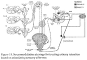
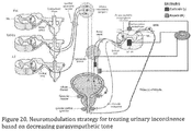
- tsDCS can be applied through implantable electrodes to manage severe conditions (e.g., dysfunctional bladder; dysfunctional anal sphincter and many others) using a benchtop, wearable or implantable stimulation system of these teachings.
- spinal-to-sciatic DCS can increase muscle tone, it has the potential to amplify muscle tone in conditions in which muscle tone is abnormally low (e.g., patients with cerebellar deficits, spinocerebellar lesions and in developmentally-delayed children, including those with Down's syndrome).
- tsDCS + pDCS spinal-to-nerve (positive to negative) or nerve-to-spinal (positive to negative) modulates spinal neuron excitability and activity, down or up, as indicated, respectively.
- the present teachings teach applications of trans-spinal DCS to affect muscle tone by modulating spinal cord excitability and is applied in treatment of living beings, in both human and veterinary applications.
- Practices of the present teachings treat hypertonic or hypotonic conditions.
- we treat a spastic hand in patients having spastic cerebral palsy by down-regulation of the high muscle tone.
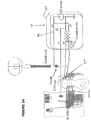
- FIGS 1-2 show an embodiment of the present teachings providing an effector organ regulating device 10 having a tsDCS - pDCS stimulation circuit 11 for modulating spinal cord excitability.
- Circuit 11 is driven by variable constant DC source S at inputs S1 and S2 (either internal to the system or from external power source).
- S1 and S2 are positive or negative.
- source S1 and the spinal electrode 20 are positive, and source S2 and the proximal distal nerve electrode 26 are negative.
- source S is switched accordingly to apply DC with S1 negative and S2 positive, and thus the spinal electrode would be cathodal and the proximal nerve electrode anodal. This switching can be accomplished internal or external to device 10, although it is preferred that all electrode sources are switched internally and simultaneously so as to avoid unwanted combinations of polarities being presented to the electrodes.
- the modulation circuit is shown having nomenclature a1, c1, a2, c2, indicating specific anodal and cathodal branches as would apply to the down-regulating embodiment of anodal spinal and cathodal nerve. More specifically, in Figure 1 this would be correct where input S1 is positive and S2 is negative, however this is a matter of illustration and not a matter of limitation of the disclosure and reversal of S1 and S2 will convert the same circuit to anodal nerve and cathodal spinal for muscle tone up-regulation. Safe operating condition is spinal current I1 equals or is greater than neural current 12.
- Regulating device 10 will either down-regulate (inhibit) or up-regulate (excite) to modulate activity associated with a target effector organ.
- the present method and apparatus can be applied to down-regulate muscle tone to relieve a fisted spastic hand and fingers or can be similarly applied to other muscles of interest.
- Direction of current flow determines function.
- Anodal spine to cathodal nerve stimulation will down-regulate muscle tone so as to reduce spasticity and rigidity, while anodal nerve to cathodal spine stimulation will up-regulate muscle tone so as to reverse flaccidity.
- FIGS 1 and 2 illustrate an example of regulation of the median nerve for resolving a chronic fisted hand and fingers with high muscle tone.
- Stimulation circuit 11 has a spinal branch 12 for supplying sub-threshold stimulation to the spinal cord 14 at a first current level I1, measured at ammeter 15, and has a neural branch 16 for supplying to the nerve of interest (e.g., median nerve) sub-threshold stimulation at a second current level 12, measured at ammeter 17.
- the current 12 is brought up to measurable EMG and then reduced to subthreshold (no apparent nerve activity).
- spinal DC is always subthreshold because of its low intensity (about 2 to 4 mA) when applied on the surface of the skin.
- these intensities might produce activity and in this case adjustment would be made to reduce currents until no apparent nerve activity is observed.
- Spinal branch 12 includes spinal electrode 20 positioned at the spinal cord 14.
- the location of electrode 20 on the spinal cord is at the cervical enlargement for upper limb muscles to be treated and at the lumbar enlargement for lower limb muscles to be treated, as will be appreciated by a person skilled in the art.
- a reference electrode 22 (return electrode) is positioned on an anterior location, such as the abdomen, as shown, or a bony location or the like.
- the nerve stimulation is charge-balanced, wherein the nerve is stimulated using an electrode array presented as charge-balancing electrode device 27 for the neural electrodes.
- This charge-balancing electrode array of device 27 has two insulated and oppositely charged electrodes 26, 28 which are mated in fixed relation on an insulating layer 29.
- This fixed device 27 is placed with the two opposite charged electrodes across the nerve segment 30, with minimized separation for the purpose of reducing the risk of damaging effects of monopolar stimulation along a greater length of the nerve as may have a long term polarizing effect.
- the rationale for creating and placing our charge-balancing electrode device 27 upon the target nerve is to reduce the potential for damaging effects of monopolar stimulation at the nerve.
- the charge-balancing electrode device 27 as described above works at the neural location to assure safe application of neural stimulation, maintaining fixed and close relation between fixed electrodes 26, 28. This shortened length of nerve that is enervated bounded by the fixed cathodal and anodal electrodes will obviate and minimize risk of any such damaging effects.
- Neural branch 16 includes a charge-balancing circuit 24 comprising variable resistor VR1 defining a first leg L1 resistively connected between input S2 and proximal electrode 26 of charge-balancing electrode device 27, and also a variable resistor VR2 defining a second leg L2 resistively connected between input S1 and distal electrode 28 of the electrode device 27. Electrodes 26, 28 of charge-balancing electrode device 27 are mounted in fixed relationship on over local nerve segment 30' of nerve 30, in this example median nerve 30 on arm 31 shown in Figure 2 .
- a first pair of electrodes 20, 22 are part of a first stimulation circuit 12 to apply trans-spinal direct current stimulation (tsDCS) to the spine 14 and a second pair of electrodes 26, 28 are part of a second stimulation circuit 16, the latter to apply stimulation to nerve 30 associated with the target body part.
- tsDCS trans-spinal direct current stimulation
- these two circuits define a resulting polarization circuit 33 defined between respective electrodes 20 and 26, shown in Figure 1 as between an anodal electrode 20 of the spinal circuit 12 and a cathodal electrode 26 of the neural circuit 16.
- the resulting polarization circuit 33 stimulates the spine and achieves a desired regulation of excitability of effected spinal motoneurons and interneurons that enables the desired outcome of regulation of muscle tone.
- the active spinal electrode 20 is preferably located at a spinal enlargement 1,2 Figure10 .
- the spinal enlargement is selected as being associated with a nerve that is associated with control of the body part of interest,
- a reference spinal electrode (second pole) is affixed at an anterior location such as at the abdomen.
- the tsDCS is applied between these two electrodes/poles to electrically polarize the zone of tissue between the two electrodes.
- the second polar circuit 16 is located at and energizes peripheral nerve 30 associated with control of the target body part (arm/hand).
- the proximal and distal electrodes 26, 28 i.e., two poles of this circuit 16 are arrayed over the target nerve 30 to define a short stimulation section 30' of that nerve between these two electrodes (poles) this limits the reach of polarization at this nerve 30.
- Such second stimulation circuit can be applied to locations in many parts of the body and the character of stimulation energy will be selected accordingly.
- peripheral nerve direct current stimulation pDCS
- pDCS peripheral nerve direct current stimulation
- Down regulation and up regulation of muscle tone are guided by the direction of the interaction between these adjacent electrodes of the spinal and neural circuits 12, 16 that define the polarization circuit 33.
- the spinal electrode 20 is positive ("anodal") and proximal peripheral nerve electrode 26 must be negative (“cathodal”).
- the proximal nerve electrode 26 is positive (“anodal") and spinal electrode must be negative (“cathodal”). This defines the needed nerve-to-spine polarization circuit 33 (polarizing current flow path) between these two energized electrodes of the two polar circuits for up-regulation.
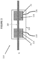
- FIG 3 shows another embodiment of charge-balancing electrode device 27 having electrode conductive pads 114, 116 mounted on non-conductive substrate 112, and as applied in contact with nerve N. Electrodes 114, 116 are attached to substrate 112 in inset metal pockets PI, P2 which are in contact with electrical leads 118, 120 (or alternatively electrodes 114, 116 are attached in direct contact with ends of the leads without using the metal pockets PI, P2).
- the electrodes are preferably sponge electrodes with conductive gel.
- the substrate 112 is 8 cm X 6 cm and the sponge pads 114, 116 are 2.5 cm square affixed in the metal pockets PI, P2 on insulating substrate 112, wherein the sponge pads are separated by 2 cm as affixed.
- neural proximal and distal electrodes 26, 28 always have opposed polarities from each other, and the polarity of spinal electrode 20 is always opposite polarity to its own reference electrode 22 and to the polarity of the proximal neural electrode 26. Reversal of polarity of the adjustable Source S and thus at S1/S2 reverses the polarity of the entire circuit 11, thus maintaining this oppositional relationship.
- the spinal electrode 20 is positive (and its reference electrode 22 is negative)
- the neural proximal electrode 26 is negative and the distal electrode 28 is positive; and vice versa when polarities of S1,S2 are reversed.
- the present teachings provides a regulating device 10 having tsDCS-pDCS stimulator 11 circuits that form the desired resulting polarization circuit 33 and that can be used either for down-regulating or up-regulating effector organ activity including muscle tone.
- an isolated power supply having two separate 18 volt battery sets supply isolated constant current to the two circuits 12, 16 from the adjustable DC source S, at S1 and S2.
- the circuit inhibits spinal motoneurons and interneurons and reduces muscle tone at the muscles associated with the stimulated nerve.
- the signals at S1 and S2 are reversed, i.e., where S2 is anode and S1 cathode, the device operates to excite spinal motoneurons and interneurons and increases activity at the effector organs, e.g., muscle(s) of interest associated with the chosen nerve being stimulated.
- current in circuit 11 was applied in the relation of spinal current I1 to distal neural current I2 sometimes at around 160:1 in mice and around 2:1 to 3:1 in humans. But in all subjects the ratio can range depending upon body size, type, age, fat level, etc., as well as the specific neurological deficit, or whether the nerve of interest is less responsive or not easily stimulated from the surface, and this will impact needed levels of current stimulation. Even so, the present teaching is easily setup and operated in veterinary and human practices even where these ratios may vary widely patient to patient.
- the electrodes of regulation device 10 are attached to the subject and the spinal circuit is properly set.
- An electromyography (EMG) device 32 is connected to monitor increased stimulation at the muscle of interest associated with the nerve as stimulated by the current flow.
- EMG electromyography
- the EMG was attached across the thumb to measure action potential at the abductor pollicis brevis muscle (on the palm side of the hand).
- the pretreatment clenched fist and EMG attachment at the thumb is indicated in Figure 1 and Figure 2 .
- Post-treatment, spasticity was reduced as the hand and thumb were now relaxed and extendable, and no longer clenched.
- the following method was followed for treatment of spastic hand in a seated patient.
- the method featured anodal spinal electrode and cathodal proximal electrode at median nerve to decrease muscle tone of a rigid hand and fingers. This is shown by way of illustration and not as limitation of the spirit and scope of the present teachings.
- Abdominal electrode cathode electrode placed over anterior abdominal skin or other location that is not a major neural location.
- Median nerve electrode placement a charge-balancing electrode device with two separate electrodes: the distal electrode (toward the hand) as anode; the proximal electrode (toward the head / cervical enlargement) as cathode.
- the double electrode set is placed over the front aspect of the wrist joint across and over a section of the median nerve.
- Electromyography electrode placement bipolar electrodes record EMG from thumb muscles, placed over the abductor pollicis brevis (APB).
- the stimulator output is brought to threshold and reduced to produce no EMG activity from the nerve/muscle.
- about 4 mA at the spinal-abdominal circuit and about 2-3.5 mA at the median nerve circuit achieves desired results in a human.
- the branch values may converge, such as 2-2.5 mA at both the nerve and spinal column.
- the adjustable power source S would be adjusted to bring the spinal circuit to about 2-2.5 mA and the variable resistor VR1-VR2 would be adjusted, thus bringing the nerve electrode set also to about 2-2.5 mA.
- the current ratio I1:I2 would be as close as 1:1.
- Typical treatment duration The duration is for 20 min. (At beginning/end of treatment ramping up/down is recommended for comfort.)
- End of treatment Turn the stimulator off (after ramping down to zero input). Inspect the skin under the electrodes for any skin changes.
- current at the spinal cord is first adjusted typically 2 - 4mA on average, depending on age and body type / size, and access to nerve, etc., as would be appreciated by a person skilled in the art.
- larger and stronger patients require higher current level, and the spinal cord accepts a much higher dose versus the current at the more sensitive target nerve.
- the nerve is buried or accessed through much tissue - possibly scarred or fatty -- a higher stimulation level of the nerve may be required.
- there is low or no divergence of the spinal and nerve values such as, for example, for an infant 2.5 mA at both spine and at nerve can be used.
- Spinal current may be reduced to reduce artifact at spinal electrode.
- electrodes are sponge-type and are applied with conductive gel.
- the direct current for spinal stimulation ranges from about 2 mA to about 5 mA for treatment of muscle tone of humans.
- peripheral stimulation is at the level of the median nerve, ulnar nerve, radial nerve, brachial plexus, or smaller branches thereof, and for treating lower limb conditions, peripheral stimulation is at the level of the femoral nerve, sciatic nerve, peroneal nerve or smaller branches thereof.
- tsDCS devices are applicable to the treatment of disorders and dysfunctions of effector organs, including treatment of muscle tone impairments in patients with cerebral palsy, Parkinson's disease, stroke, traumatic brain injury, spinal cord injury, restless leg syndrome, spastic paraplegia, cerebellar lesions, developmental disorders such as Down's syndrome, specific genetic diseases with muscle tone impairment, and many other disorders affecting control of skeletal muscle.
- Anodal spinal to cathodal proximal nerve treatment is used for high muscle tone treatment, for example: spasticity and rigidity from various sources, including after stroke; spasticity after spinal cord injury; spasticity and rigidity in cerebral palsy; rigidity in Parkinson's patients; spasticity after traumatic brain injury; dystonia.
- Anodal nerve to cathodal spinal treatment is used for low muscle tone and flaccidity, such as due to genetic disorders (e.g. Down's syndrome) or due to disease, or cerebellar and other traumas including those caused by surgical interventions; among other cases.
- Electrode placement depends upon location of the muscles of interest and then upon identifying the associated nerve to be stimulated.
- Major nerve associations are shown in Figure 4 for preferred electrode placement in human subjects for down-regulating muscle tone.
- cervical or lumbar spinal electrodes are biased positive and the electrodes of the charge-balancing electrode device at the nerve of interest are presented negative (proximal) / positive (distal).
- peripheral stimulation is applied to the listed nerves associated with spinal stimulation with the indicated result of reduced muscle tone and reduced spasticity in the following combinations:
- the spinal branch 12 biases spinal electrodes 20, 22 and the nerve branch 16 biases the nerve set of electrodes of charge-balancing electrode array of device 27 in their complementary arrangements to achieve the desired current flow from anodal spine to cathodal nerve (muscle tone reducing) or from anodal nerve to cathodal spine (muscle tone increasing).
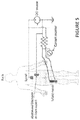
- Figure 5 shows spinal-to-sciatic or sciatic-to-spinal treatment for muscles innervated by the sciatic nerve for either down or up-regulating muscle tone in the leg, depending upon signal polarity applied from the source.
- the configuration shown in Figure 5 with anodal spinal electrode is for down-regulation.
- a packaged regulator system 50 includes a stimulator system and may be wearable, implantable, or stationary.
- a stimulator system in an exemplary system 50 incorporating the stimulation system 10 and muscle tone stimulator circuit 11 as earlier described, has an external spinal circuit 12* formed by coupling spinal electrodes 20, 22 via wires 72, 76 to male jack 70 having pins 74, 77 connecting to pins 56,58 at mating female receptacle 54 on the system 50 housing, and which then is connected to the earlier described spinal branch 12.
- An external neural circuit 16* is established by coupling neural electrodes 26 and 28 of charge-balancing electrode device 27 via wires 84, 86 to male jack 82 having pins 87, 89 for mating with receiver pins 62, 64 at mating female receptacle 60 on the system 50 housing, and which then is connected to the earlier described neural branch 16.
- spinal jack 70 preferably includes a detent feature 80 which must be accommodated by a cooperating detent feature 60 so as to enable mating of jack 70 and receptacle 54 in only one position to assure correct circuit connection. This arrangement assures that spinal electrode 20 will always be coupled via wire 72 and jack 70 to pin 56 of receptacle 54 and reference electrode 22 will always be coupled via wire 76 and jack 70 to pin 58 of receptacle 54.
- neural jack 82 preferably includes a detent feature 88 which must be accommodated by a cooperating detent feature 68 so as to enable specific mating of jack 82 and receptacle 60 in only one orientation to assure correct circuit connection for the charge-balancing electrode device 27. This arrangement assures that to assure correct signals are delivered to the correct electrodes and lessens the opportunity for human error in operation of the system.
- electrode 20 is a sponge electrode and is color-coded such as with a blue marking ("B") and correspondingly electrode 26 of charge-balancing electrode device 27 is of opposite polarity and is color-coded with a marking ("B").
- Reference electrode 22 and distal electrode 28 are black.
- the spinal electrodes 20, 22 are attached via jack 70 to system 50 and polarities are set for down-regulation or up-regulation, respectively, by user interaction with controller 90 and touch display 92. Controller 90 then assures that charge-balancing electrode device 27, attached via jack 82 to system 50, presents the blue-coded electrode 26 at opposite polarity to the other polarity of the blue-coded spinal electrode 20. This then assures that the resulting polarization circuit 33 is properly formed.
- the user applies the spinal electrode 20 to the spine as earlier described.
- the user notes the blue-tagging and is reminded that the charge-balancing electrode device 27 must be placed over the nerve of interest with the blue-coded electrode 26 oriented proximal to the spinal electrode 20 and electrode 28 oriented distal to the spinal electrode 20.
- the trained administrator always affixes the blue-coded spinal electrode 20 at the spine at the desired location and black-coded reference electrode 22 on a non-nerve location, as earlier discussed, and affixes the charge-balancing electrode device 27, preferably at an angle, e.g., at 90 degrees, across the nerve of interest (e.g., nerve 30, Figure 1 ), to define a short length of nerve segment 30' to be stimulated, such that the oppositely-biased blue-coded electrode 26 of charge balancing electrode device 27 will be proximal to the blue-coded spinal electrode 20 and the black-coded reference electrode 28 of charge-balancing electrode device 27 will be distal to spinal electrode 20, all with appropriate polarities fixed. Signal levels are again adjusted as earlier discussed.
- Blue spinal electrode 20 is positive for down-regulation (or negative for up-regulation) and is paired with proximal blue-coded electrode 26 which is oppositely negative (or positive) biased, while black reference electrode 22 is negative (or positive) and distal black electrode 28 is positive (or negative), respectively.
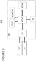
- a regulation system 100 of these teachings shown in Figure 9 includes the above electrodes and jacks, formed as spinal connection device 12* and neural connection device 16*, for mating with receptacles 54, 60, of the included system 50, respectively.
- the system 100 includes DC power as part of or as supplied at DC source 94 which is controlled by controller circuit 90 for supplying and driving circuit 11 and for biasing electrodes 20, 22, 26, 28 via connection devices 12* and 16*.
- Figure 6 shows an external power source but either internal or external power source can be used for portable or workstation installation within practice of these teachings. Rechargeable batteries would be adequate.
- User control interface is provided at touch screen and display 92. Power is adjusted at variable resistor 51 and VR1-VR2 resistive set 52 according to indications at ammeters 15/17.
- the present teachings teach benchtop, wearable and implantable stimulation systems utilizing trans-spinal direct current stimulation for control of effector organs.
- Embodiments of these teachings enable regulation of effector organs and in one embodiment control of muscle tone. This may be achieved with a medical device with two sets of electrodes that are attached to the patient to provide spinal stimulation and peripheral stimulation, and may be presented as a benchtop stimulation system.
- wearable or implantable stimulation devices may be employed.
- administration of tsDCS therapy for disorders at effector organs will be sufficient if done between 1-5 times a week for a number of sessions on an outpatient basis. Indeed, we have seen beneficial results after a single treatment in a child with cerebral palsy who had clenched fists that had never been able to open spontaneously until treatment with an embodiment of the present teachings enable resolution of his hypertonia.
- tsDCS for some patients, treatment on such a schedule will be insufficient. Constant application of tsDCS, or application for several hours or sessions per day, for practical beneficial effects may be indicated for some. This can be assisted by enabling mobile delivery of such therapy.
- embodiments of the present teachings are presented as a wearable on-skin device or implantable device as shown in Figures 4 and 13 . Such devices are compact versions of these teachings.
- the device footprint is shrunk to the approximate diameter of a silver dollar, and is attached to the skin surface of the spine with adhesive mounting, implanted magnets, or other methodologies.
- Pre-programming of microprocessor with memory 91 ( Figure 9 ) provides the capability to accommodate such long-term treatment, with adequate internal monitoring.
- a tsDCS stimulation device delivers either anodal or cathodal direct current stimulation to the desired location on the spine, and in one practice with the tsDCS device here taught, device 120, Figure 10 , serves as the dorsal electrode 122 and the reference electrode 124 is placed on the skin surface of either the neck, abdomen, or other level depending on the spinal level of stimulation, neck attachment shown in Figure 10 .
- An electrode lead 126 runs along the skin from the wearable tsDCS device to the ventral skin-surface electrode 124.
- the wearable tsDCS device 120 comes in different sizes and form factors depending on whether it is being used with adults or children, and depending on the spinal location it is being used for.
- the wearable tsDCS device can be rechargeable, and removed at night for charging and comfort of sleep.
- the wearable tsDCS device attaches to the skin surface of the spine at either the cervical, thoracic, lumbar or sacral levels depending on the effector organ to be stimulated.
- Peripheral nerve stimulation can be done through skin-surface electrodes, subcutaneous electrodes, or implanted electrodes.
- the autonomic nervous system controls and regulates numerous bodily functions including heart rate, respiration, digestion, urination, sexual response and others and consists of two major divisions, the sympathetic nervous system and the parasympathetic nervous system, shown in Figure 11 .
- Activation of the sympathetic nervous system results in preparation of the body for stressful or emergency situations, while activation of the parasympathetic nervous system results in conservation and restoration and controls body processes during normal situations.
- the present teaching including our wearable tsDCS device, by modulating spinal circuits at relevant spinal levels, can either activate or inhibit various parts of the sympathetic nervous system or the parasympathetic nervous system.
- Normal functions to be regulated by a tsDCS device of these teachings that modulate sympathetic or parasympathetic activity include modulating bronchodilation in the airways, modulating vasoconstriction in the skin and organs, stimulating gluconeogenesis and glucose release from the liver, stimulating secretion of epinephrine and norepinephrine by the adrenal gland, modulation of sweating, slowing or increasing heart rate, modulating tidal volume and rate of respiration, slowing or increasing intestinal processes involved with digestion, modulating urine production, modulating bladder contraction, modulating sphincter control, stimulating erection and sexual arousal, and others.
- Table 5 shows spinal levels of sympathetic outflow for various organs. Table 5.
- Segmental sympathetic supplies Location or organ Spinal level Head and neck T1-5 Upper limb T2-5 Lower limb T10-L2 Heart T1-5 Bronchi and lungs T2-4 Esophagus T5-6 Stomach T6-10 Small intestine T9-10 Large intestine (to splenic flexure) T11-L1 Large intestine (splenic flexure to rectum) L1-2 Liver and gallbladder T7-9 Spleen T6-10 Pancreas T6-10 Kidney T10-L1 Suprarenal T8-L1 Urinary bladder T11-L2
- dysautonomias there are numerous disorders of the ANS that have been described and are referred to as dysautonomias, and can be due to failure or disruption of either the sympathetic or parasympathetic divisions of the ANS.
- Specific such disorders include autoimmune autonomic ganglionopathy, congenital central hypoventilation syndrome, familiar dysautonomia, Holmes-Adie syndrome, multiple system atrophy, Shy-Drager syndrome, neurally mediated syncope, orthostatic hypotension, postural tachycardia syndrome, striatonigral degeneration, vasovagal syncope and others.
- our tsDCS devices treat autonomic disorders that currently have no effective treatments.
- tsDCS is paired with stimulation of a peripheral nerve to an effector organ (e.g., muscle).
- Applications include modulating muscle tone in skeletal muscle, with surface or implantable electrodes.
- Implantable electrodes and an implantable tsDCS stimulator embodiment of these teachings enable stimulation of smooth muscle such as that of bladder and bladder sphincters, anal sphincters, visceral organs, airways, heart, digestive organs, glands and other.
- the processes and disorders of the ANS listed above can in some instances be modulated more efficiently via an implanted electrode.
- the implanted electrodes preferably are at the nerve leading to the smooth muscle, striated muscle or at a ganglion or plexus associated with the ANS. This location can be directly at the sympathetic trunk or ganglia, celiac ganglion, superior mesenteric ganglion, inferior mesenteric ganglion, or by applying stimulation at the post-ganglionic nerve.
- the parasympathetic nervous system has ganglia in close proximity to or located in the organs being innervated, and implantable electrodes can be placed in proximity to these parasympathetic ganglia.
- regulating device 10 is provided as a wearable or implantable regulating device 50, having the tsDCS-pDCS stimulation circuit 11 in a housing H. This would be for use with implantable electrode leads used for stimulation in practice of embodiments of these teachings. This may also include use as an implantable DC stimulator.
- implantable electrode leads used for stimulation in practice of embodiments of these teachings.
- This may also include use as an implantable DC stimulator.
- we can treat flaccid, spastic or rigid conditions by use of an implantable electrode for deep nerves to resolve a need for on-demand, frequent or continuous stimulation.
- FIG 14 An illustrative use is shown in Figure 14 for treating incontinence, such as fecal or urinary, as muscle tone abnormalities.
- the muscle of the bladder can suffer either from excessive muscle tone or low muscle tone.
- a table top, wearable or implantable stimulator of these teachings can be used to up or down regulate that muscle tone.
- the anode would be implanted over the epidural surface of the sacral segments of the spinal cord and an implantable electrode cathode 27* would be implanted over the sacral nerves at the level of S2 to S4 as shown.
- the reverse polarities would be used for low muscle tone (flaccid bladder)
- Device 100 is also provided with a microprocessor with memory 91 in Figure 9 , which enables pre-programmed operation, or responsive remote operation via a communication link 99.
- Controller circuit 90 monitors the DC source and depending upon direction of the current establishes either anodal-spinal down-regulate mode or the opposite up-regulate mode, and illuminates either a down-regulate indicator 96 or an up-regulate indicator 98 for the reverse, for further assuring safe operation of system 100.
- This configuration may be used for urinary control as shown or for fecal control when applied to control the anal sphincter. This configuration may also be used for any other muscle problem that requires specific muscle tone control. Embodiments of these teachings thus enable treatment of humans using a wearable or implantable stimulation system.
- the kidney is responsible for excretion of the products of metabolism and removal of excess water, also having endocrine functions by producing erythropoietin, renin and other factors.
- Neural control of kidney and adrenal gland is shown in Figure 15 .
- Sympathetic control is by sympathetic efferents from T10-L1 that run via the sympathetic trunk and the splanchnic nerves to the celiac ganglion and aortiocorenal ganglion.
- Post-ganglionic fibers contribute to the renal plexus which gives rise to the renal nerves that supply the kidney and its blood vessels, glomeruli and tubules.
- Stimulation of the renal nerves leads to increased vasoconstriction of the blood vessels supplying the kidney, decreased removal of water and sodium from the blood, and increased renin secretion.
- Parasympathetic control is from the vagus nerve, which arises from the dorsal motor nucleus of the vagus nerve in the brainstem.
- HTN hypertension
- CHF congestive heart failure
- this is achieved by applying anodal tsDCS with cathodal and anodal electrodes applied at the spinal level of T10-L1 as shown in Figure 15 .
- this is augmented with electrical inhibition of the renal nerves using implanted neural electrodes, and in one embodiment further including respective cathodal and anodal neural electrodes applied as shown in Figure 15 .
- Such an approach can be used to treat HTN, CHF, obesity and other disorders.
- cathodal tsDCS is applied at the level of the dorsal motor nucleus of the vagus nerve in the brainstem and electrical stimulation is applied to the pre-ganglionic fibers of the vagus nerve using implanted electrodes, as shown in Figure 13 .
- Cathodal tsDC to the vagal nucleus in this embodiment is applied with electrodes at T1-T2 and at the cranial apex.
- cathodal tsDCS to the vagal nucleus is applied with electrodes applied bilaterally to the mastoid processes of the skull. Such an approach could be used to treat HTN, CHF, obesity and other diseases.
- the bladder functions as a reservoir and is responsible for storing urine that has been formed by the kidneys in the process of eliminating metabolites and excess water from the blood.
- the stored urine is released via the urethra in the process of micturition.
- sympathetic control is from sympathetic efferents from T11-L2 that run via the sympathetic trunk and the splanchnic nerves to the inferior mesenteric ganglion.
- Post-ganglionic fibers contribute to the hypogastric plexus and reach the bladder where they synapse on the detrusor muscle, and also synapse on the sphincter vesicae at the bladder neck.
- Parasympathetic control is from parasympathetic fibers that arise from S2-S4 and travel via the pelvic splanchnic nerves to synapse on post-ganglionic neurons located in a dense plexus among the detrusor smooth muscle cells in the wall of the bladder.
- Post-ganglionic parasympathetic fibers cause contraction of the bladder detrusor muscle and relaxation of the sphincter vesicae.
- the external urethral sphincter (EUS) consists of striated muscle and is under voluntary control via alpha motor neurons in Onuf's nucleus in the ventral horns of S2-S4.
- Urinary retention is an inability to empty the bladder completely and can be acute or chronic. Retention can be due to numerous issues, including constipation, prostatic enlargement, urethral strictures, urinary tract stones, tumors, and nerve conduction problems. Such nerve conduction problems are seen in brain and spinal cord injuries, diabetes, multiple sclerosis, stroke, pelvic surgery, heavy metal poisoning, aging and idiopathically. These result in either weak bladder contraction and/or excess sphincter activation. As such, modulation strategies that enable improved emptying of the bladder are of therapeutic interest.
- Urinary incontinence is loss of bladder control leading to mild leaking all the way up to uncontrollable wetting. It results from weak sphincter muscles, overactive bladder muscles, damage to nerves that control the bladder from diseases such as multiple sclerosis and Parkinson's disease, and can occur after prostate surgery. As such, modulation strategies that treat urinary incontinence are of therapeutic interest.
- parasympathetic tone A decrease in parasympathetic tone would result in relaxation of bladder contraction and contraction of the sphincter vesicae.
- this is achieved by applying anodal tsDCS with cathodal and anodal electrodes applied at the spinal level of S2-S4 as shown in Figure 20 .
- this is augmented with electrical inhibition of the parasympathetic preganglionic fibers in pelvic splanchnic nerves using implanted electrodes, and in one embodiment further including respective cathodal and anodal neural electrodes applied as shown in Figure 20 .
- the gastrointestinal (GI) system is responsible for digesting our food.
- the GI system is a series of hollow organs joined in a long tube going from mouth to anus, and includes the esophagus, stomach, small intestines, large intestines and rectum.
- the liver, pancreas and gallbladder are solid organs of the digestive system. Proper functioning of these hollow organs, together with the enzymes and molecules produced by these solid organs, and the collection of microrganisms colonizing the GI system referred to as the microbiome, is critical for processing, digestion and elimination of foodstuffs.
- Sympathetic control of the stomach, small intestines and large intestines is by sympathetic efferents from T6-L2 that traverse the sympathetic trunk and the splanchnic nerves (greater, lesser, least and lumbar splanchnics) to reach a network of three ganglia.
- These ganglia are the celiac ganglion, superior mesenteric ganglion (SMG) and the inferior mesenteric ganglion (IMG), which contain the cell bodies of post-ganglionic sympathetic neurons.
- Parasympathetic control of the stomach, small intestines, ascending colon and transverse colon is from the vagus nerve, while parasympathetic control of the distal transverse colon, descending colon and rectum is from S2-S4.
- Cell bodies of parasympathetic neurons located in the ventral horns of S2-S4 send fibers through the pelvic nerves to post-ganglionic neurons located in Auerbach's (myenteric) and Meissner's (submucosal) plexuses. These post-ganglionic neurons synapse on the smooth muscle and glands of the gastrointestinal tract they innervate. Stimulation of the parasympathetic system results in peristalsis, secretion from glands, and relaxation of sphincters, leading to increased GI motility.
- GI motility disorders are due to either decreased or increased motility, a term used to describe the contraction of the muscles that mix and propel contents in the GI tract. These include disorders such as chronic intestinal pseudo-obstruction, irritable bowel syndrome, constipation, gastroesophageal reflux disease, dumping syndrome, intestinal dysmotility, diabetic gastroparesis, Hirschsprung's disease, gastroparesis, achalasia, small bowel bacterial overgrowth, diarrhea, functional heartburn, functional dysphagia, functional dyspepsia, postprandial distress syndrome, epigastric pain syndrome, aerophagia, functional vomiting, chronic idiopathic nausea, functional bloating, functional abdominal pain disorder, functional sphincter of Oddi disorder, and other functional disorders. Beyond motility disorders, inflammatory immune-mediated disorders such as Crohn's disease and ulcerative colitis also have mechanisms that are responsive to autonomic control.
- increased motility is achieved by applying anodal tsDCS with cathodal and anodal electrodes applied at the spinal level of T6-L2 as shown in Figure 22 .
- this is augmented with electrical inhibition of the post-ganglionic nerve fibers distal to the celiac ganglion, SMG and IMG, using implanted electrodes, and in one embodiment further including respective cathodal and anodal neural electrodes applied as shown in Figure 22
- Increase parasympathetic tone results in increased peristalsis and secretion.
- increased motility is achieved by applying cathodal tsDCS with cathodal and anodal electrodes applied at the spinal level of S2-S4 as shown in Figure 23 .
- this is augmented with electrical excitation of the pre-ganglionic pelvic nerves using implanted neural electrodes, and in one embodiment further including respective cathodal and anodal neural electrodes applied as shown in Figure 23 .
- cathodal tsDCS is applied at the level of the dorsal motor nucleus of the vagus nerve in the brainstem and electrical stimulation is applied to the pre-ganglionic fibers of the vagus nerve using implanted electrodes.
- Cathodal tsDC to the vagal nucleus in this embodiment is applied with electrodes at T1-T2 and at the cranial apex.
- cathodal tsDCS to the vagal nucleus is applied with electrodes applied bilaterally on the mastoid process.
- this decreased motility is achieved by applying cathodal tsDCS with cathodal and anodal electrodes applied at the spinal level of T6-L2.
- this is augmented with electrical excitation of the post-ganglionic nerve fibers in and distal to the hypogastric plexus using implanted neural electrodes, and in one embodiment further including respective cathodal and anodal neural electrodes in practice of the invention.
- this decreased motility is achieved by applying anodal tsDCS with cathodal and anodal electrodes applied at the spinal level of S2-S4. In a further embodiment, this is augmented with electrical inhibition of the pre-ganglionic pelvic nerves using implanted neural electrodes, and in one embodiment further including respective cathodal and anodal neural electrodes in practice of these teachings.
- the anal sphincters are responsible for maintaining control over rectal contents. Sympathetic outflow is from L1-L2, with pre-ganglionic fibers traversing the sympathetic chain and synapsing on post-ganglionic neurons in the IMG. Post-ganglionic sympathetic fibers run via the hypogastric nerve, hypogastric plexus and pelvic nerves to innervate the internal anal sphincter (IAS). Sympathetic stimulation maintains IAS contraction.
- the internal anal sphincter receives parasympathetic supply from S2-S4 outflow, and its contraction is inhibited by parasympathetic fiber stimulation.
- the striated sphincter muscles (external anal sphincter and puborectalis muscle) are under voluntary control and are innervated by somatic efferent fibers traveling in the pudendal nerve (S2-S4).
- Dysfunction of the anal sphincter leads to fecal incontinence, which results in leakage or inability to retain gas and/or solid feces. It results from weak or damaged sphincter muscles, and damage to nerves that control the sphincters from disorders such as multiple sclerosis, Parkinson's disease, spinal cord injury, brain injury and stroke. As such, modulation strategies that treat fecal incontinence are of significant therapeutic interest.
- Increase sympathetic tone results in increased contraction of the IAS.
- increased IAS contraction is achieved by applying cathodal tsDCS with cathodal and anodal electrodes applied at the spinal level of L1-L2 as shown in Figure 24 .
- this is augmented with electrical excitation is applied to the post-hypogastric plexus pelvic nerves using implanted neural electrodes, and in one embodiment further including respective cathodal and anodal neural electrodes applied as shown in Figure 24 .
- cathodal tsDCS is applied at the level of S2-S4 with cathodal and anodal electrodes applied as shown in Figure 26 .
- this is augmented with electrical excitation of the pudendal nerve applied using implanted neural electrodes, and in one embodiment further including respective cathodal and anodal neural electrodes applied as shown in Figure 26 .
- embodiments of the present teachings feature tsDCS spinal stimulation.
- this tsDCS stimulation is augmented with a neural stimulation.
- peripheral pDCS is continuous, non-varying, steady-state direct current stimulation
- stimulation of a peripheral nerve or autonomic nerve fiber associated with an effector organ may include pulsed electrical stimulation, functional electrical stimulation, continuous DCS, pulsed DCS, or other alternating signals.
- the present teachings also may be practiced with wireless microstimulators (see, for example, US Patent 5,193,539 , A Programmable Implantable Microstimulator SoC, IEEE TRANSACTIONS ON BIOMEDICAL CIRCUITS AND SYSTEMS, VOL. 5, NO. 6, DECEMBER 2011 , both of which are incorporated by reference herein in their entirety and for all purposes) with Wireless Telemetry, micro-coil magnetic stimulation (see, for example, Magnetic Stimulation of Subthalamic Nucleus Neurons using
- peripheral stimulation is continuous steady-state and non-varying.
- excitation or inhibition of a stimulated autonomic nerve fiber depends on the frequency of the applied electrical stimulation.
- inhibition of parasympathetic fibers is achieved with high-frequency electrical stimulation (greater than about 50-100 Hz), while excitation of parasympathetic fibers is achieved with low-frequency electrical stimulation (less than about 50-100 Hz).
- inhibition of sympathetic fibers is achieved with high-frequency electrical stimulation (greater than about 50-100 Hz), while excitation of sympathetic fibers is achieved with low-frequency electrical stimulation (less than about 50-100 Hz).
- a series of implanted electrode leads for stimulation of multiple nerves leading to multiple organs is provided.
- one useful constellation of functions to modulate for a specific scenario includes increasing airway bronchodilation, increasing adrenal gland production of adrenergic hormones, and increasing hepatic glucose production and release in anticipation of an intense burst of physical activity.
- Brain signals to the sympathetic nervous system traversing the spinal cord are amplified by the wearable tsDCS device, which may also stimulate multiple nerves involved in multiple functions.
- a neuromodulatory approach to the amplification of the "fight-or-flight" response is enabled.
- the tsDCS device is fully implantable, with electrode leads from the device to dorsal spinal location and ventral location tunneled subcutaneously. Electrode leads from the tsDCS device which function for peripheral stimulation are also tunneled subcutaneously with electrodes implanted on the appropriate nerves of the effector organ being modulated. In another embodiment, the tsDCS device remains external to the body and wearable, but has electrode leads for peripheral stimulation that are either surface mounted or implanted.
- a wearable tsDCS unit that wirelessly controls an implanted stimulator is combined with a sensor that detects a relevant physiological state to form a closed-loop system.
- the wearable tsDCS unit wirelessly communicates with the sensor, which could be either implanted or wearable, and activates tsDCS spinal stimulation and stimulation of an effector organ via the implanted stimulator, when it detects a relevant state.
- the sensor can be configured to detect blood pressure, heart rate, body temperature, respiration rate, skin turgor, skin conductivity, oxygenation state, bladder pressure, urine osmolarity, hemodynamic parameters, specific cardiac rhythms by EKG, urethral pressure, anal sphincter pressure, muscle contraction state by EMG, specific brain waves by EEG, electrolytes, specific proteins and signaling molecules in specific tissue compartments, blood glucose concentration, gastric pH, gastrointestinal motility sounds, environmental cues such as specific sights, sounds and signals, and other parameters depending on intended application.
- the neuromodulation system is thus activated upon sensing a specific state, and inactivated when that state no longer holds.
- the system also includes a sensor configured to detect a predetermined parameter, such as those listed herein above, and configured to provide a sensed value of the predetermined parameter to the controller component.
- the controller component is further configured to initiate stimulation, initiation of stimulation determined by whether the sensed value is less than or exceeds a predetermined value denoting the specific state.
- Another embodiment includes method and apparatus for neuromodulatory regulation of effector organs by modulation of spinal neurons, having anode and cathode sources, having a spinal circuit for biasing a spinal electrode at a first polarity and biasing a distal reference electrode at a second polarity, and having a neural circuit for biasing a nerve associated with the muscle, the neural circuit having a charge-balancing electrode device having a first and second neural electrodes for limiting the polarizing effect of current flow in the nerve, the neural circuit biasing the first neural electrode to the second polarity and the second neural electrode at the first polarity, wherein the spinal electrode and the second neural electrode are connected to one of the sources and the first electrode is connected to the other of the sources, for activation of the effector organ of interest, as described in embodiments above.
- a communication device may constitute a form of a computing device and may at least include a computing device.
- the computing device may include an inter-connect (e.g., bus and system core logic), which can interconnect such components of a computing device to a data processing device, such as a processor(s) or microprocessor(s), or other form of partly or completely programmable or pre-programmed device, e.g., hard wired and or application specific integrated circuit ("ASIC") customized logic circuitry, such as a controller or microcontroller, a digital signal processor, or any other form of device that can fetch instructions, operate on pre-loaded/pre-programmed instructions, and/or followed instructions found in hard-wired or customized circuitry to carry out logic operations that, together, perform steps of and whole processes and functionalities as described in the present disclosure.
- a data processing device such as a processor(s) or microprocessor(s), or other form of partly or completely programmable or pre-programmed device, e.g., hard wired and or application specific integrated circuit (“ASIC") customized logic circuitry, such as a controller or microcontroller, a digital signal
- Each computer program may be implemented in any programming language, such as assembly language, machine language, a high-level procedural programming language, or an object-oriented programming language.
- the programming language may be a compiled or interpreted programming language.
- Each computer program may be implemented in a computer program product tangibly embodied in a computer-readable storage device for execution by a computer processor. Method steps of these teachings may be performed by a computer processor executing a program tangibly embodied on a computer-readable medium to perform functions of these teachings by operating on input and generating output.
- various functions, functionalities and/or operations may be described as being performed by or caused by software program code to simplify description.
- a computing device e.g., including a processor, such as a microprocessor, microcontroller, logic circuit or the like.
- the functions and operations can be implemented using special purpose circuitry, with or without software instructions, such as using Application-Specific Integrated Circuit (ASIC) or Field-Programmable Gate Array (FPGA), which may be programmable, partly programmable or hard wired.
- ASIC Application-Specific Integrated Circuit
- FPGA Field-Programmable Gate Array
- the application specific integrated circuit (“ASIC") logic may be such as gate arrays or standard cells, or the like, implementing customized logic by metalization(s) interconnects of the base gate array ASIC architecture or selecting and providing metalization(s) interconnects between standard cell functional blocks included in a manufacturer's library of functional blocks, etc.
- ASIC application specific integrated circuit
- Embodiments can thus be implemented using hardwired circuitry without program software code/instructions, or in combination with circuitry using programmed software code/instructions.
- the techniques are limited neither to any specific combination of hardware circuitry and software, nor to any particular tangible source for the instructions executed by the data processor(s) within the computing device. While some embodiments can be implemented in fully functioning computers and computer systems, various embodiments are capable of being distributed as a computing device including, e.g., a variety of forms and capable of being applied regardless of the particular type of machine or tangible computer-readable media used to actually effect the performance of the functions and operations and/or the distribution of the performance of the functions, functionalities and/or operations.
- the interconnect may connect the data processing device to define logic circuitry including memory.
- the interconnect may be internal to the data processing device, such as coupling a microprocessor to on-board cache memory or external (to the microprocessor) memory such as main memory, or a disk drive or external to the computing device, such as a remote memory, a disc farm or other mass storage device, etc.
- microprocessors one or more of which could be a computing device or part of a computing device, include a PA-RISC series microprocessor from Hewlett-Packard Company, an 80x86 or Pentium series microprocessor from Intel Corporation, a PowerPC microprocessor from IBM, a Sparc microprocessor from Sun Microsystems, Inc, or a 68xxx series microprocessor from Motorola Corporation as examples.
- PA-RISC series microprocessor from Hewlett-Packard Company
- 80x86 or Pentium series microprocessor from Intel Corporation
- PowerPC microprocessor from IBM
- Sparc microprocessor from Sun Microsystems, Inc
- 68xxx series microprocessor from Motorola Corporation as examples.
- the inter-connect in addition to interconnecting such as microprocessor(s) and memory may also interconnect such elements to a display controller and display device, and/or to other peripheral devices such as input/output (I/O) devices, e.g., through an input/output controller(s).
- I/O devices can include a mouse, a keyboard(s), a modem(s), a network interface(s), printers, scanners, video cameras and other devices which are well known in the art.
- the inter-connect may include one or more buses connected to one another through various bridges, controllers and/or adapters.
- the I/O controller includes a USB (Universal Serial Bus) adapter for controlling USB peripherals, and/or an IEEE- 1394 bus adapter for controlling IEEE- 1394 peripherals.
- USB Universal Serial Bus
- the memory may include any tangible computer-readable media, which may include but are not limited to recordable and non-recordable type media such as volatile and non-volatile memory devices, such as volatile RAM (Random Access Memory), typically implemented as dynamic RAM (DRAM) which requires power continually in order to refresh or maintain the data in the memory, and non-volatile RAM (Read Only Memory), and other types of non-volatile memory, such as a hard drive, flash memory, detachable memory stick, etc.
- Non-volatile memory typically may include a magnetic hard drive, a magnetic optical drive, or an optical drive (e.g., a DVD RAM, a CD RAM, a DVD or a CD), or 'other type of memory system which maintains data even after power is removed from the system.
- the term “substantially” is utilized herein to represent the inherent degree of uncertainty that may be attributed to any quantitative comparison, value, measurement, or other representation.
- the term “substantially” is also utilized herein to represent the degree by which a quantitative representation may vary from a stated reference without resulting in a change in the basic function of the subject matter at issue.
Landscapes
- Health & Medical Sciences (AREA)
- Life Sciences & Earth Sciences (AREA)
- Engineering & Computer Science (AREA)
- Biomedical Technology (AREA)
- Nuclear Medicine, Radiotherapy & Molecular Imaging (AREA)
- Radiology & Medical Imaging (AREA)
- Animal Behavior & Ethology (AREA)
- General Health & Medical Sciences (AREA)
- Public Health (AREA)
- Veterinary Medicine (AREA)
- Neurology (AREA)
- Neurosurgery (AREA)
- Orthopedic Medicine & Surgery (AREA)
- Heart & Thoracic Surgery (AREA)
- Molecular Biology (AREA)
- Cardiology (AREA)
- Physical Education & Sports Medicine (AREA)
- Biophysics (AREA)
- Electrotherapy Devices (AREA)
- Magnetic Treatment Devices (AREA)
- Stabilization Of Oscillater, Synchronisation, Frequency Synthesizers (AREA)
- Amplifiers (AREA)
- Amplitude Modulation (AREA)
- Steroid Compounds (AREA)
- Gastroenterology & Hepatology (AREA)
Priority Applications (4)
| Application Number | Priority Date | Filing Date | Title |
|---|---|---|---|
| PL14872635T PL3082947T3 (pl) | 2013-12-22 | 2014-12-22 | Systemy przezrdzeniowej modulacji prądem stałym |
| EP19161879.2A EP3581239B1 (en) | 2013-12-22 | 2014-12-22 | Trans-spinal direct current modulation systems |
| SI201431236T SI3082947T1 (sl) | 2013-12-22 | 2014-12-22 | Sistemi trans-spinalne modulacije z enosmernim tokom |
| HRP20191032TT HRP20191032T1 (hr) | 2013-12-22 | 2019-06-07 | Trans-spinalni modulacijski sustavi istosmjerne struje |
Applications Claiming Priority (4)
| Application Number | Priority Date | Filing Date | Title |
|---|---|---|---|
| US201361919806P | 2013-12-22 | 2013-12-22 | |
| US201461925423P | 2014-01-09 | 2014-01-09 | |
| US201462092214P | 2014-12-15 | 2014-12-15 | |
| PCT/US2014/071959 WO2015095880A2 (en) | 2013-12-22 | 2014-12-22 | Trans-spinal direct current modulation systems |
Related Child Applications (1)
| Application Number | Title | Priority Date | Filing Date |
|---|---|---|---|
| EP19161879.2A Division EP3581239B1 (en) | 2013-12-22 | 2014-12-22 | Trans-spinal direct current modulation systems |
Publications (3)
| Publication Number | Publication Date |
|---|---|
| EP3082947A2 EP3082947A2 (en) | 2016-10-26 |
| EP3082947A4 EP3082947A4 (en) | 2018-08-22 |
| EP3082947B1 true EP3082947B1 (en) | 2019-03-13 |
Family
ID=53403908
Family Applications (2)
| Application Number | Title | Priority Date | Filing Date |
|---|---|---|---|
| EP19161879.2A Active EP3581239B1 (en) | 2013-12-22 | 2014-12-22 | Trans-spinal direct current modulation systems |
| EP14872635.9A Active EP3082947B1 (en) | 2013-12-22 | 2014-12-22 | Trans-spinal direct current modulation systems |
Family Applications Before (1)
| Application Number | Title | Priority Date | Filing Date |
|---|---|---|---|
| EP19161879.2A Active EP3581239B1 (en) | 2013-12-22 | 2014-12-22 | Trans-spinal direct current modulation systems |
Country Status (20)
| Country | Link |
|---|---|
| US (3) | US9283391B2 (sl) |
| EP (2) | EP3581239B1 (sl) |
| JP (1) | JP6518251B2 (sl) |
| KR (2) | KR102431161B1 (sl) |
| CN (2) | CN106029164B (sl) |
| AU (1) | AU2014368874B2 (sl) |
| CA (1) | CA2932000C (sl) |
| CY (1) | CY1122116T1 (sl) |
| DK (1) | DK3082947T3 (sl) |
| ES (2) | ES2889099T3 (sl) |
| HR (1) | HRP20191032T1 (sl) |
| HU (1) | HUE045175T2 (sl) |
| IL (1) | IL246430B (sl) |
| LT (1) | LT3082947T (sl) |
| MX (1) | MX366919B (sl) |
| PL (1) | PL3082947T3 (sl) |
| PT (1) | PT3082947T (sl) |
| SG (1) | SG11201604288WA (sl) |
| SI (1) | SI3082947T1 (sl) |
| WO (1) | WO2015095880A2 (sl) |
Families Citing this family (72)
| Publication number | Priority date | Publication date | Assignee | Title |
|---|---|---|---|---|
| US11051744B2 (en) | 2009-11-17 | 2021-07-06 | Setpoint Medical Corporation | Closed-loop vagus nerve stimulation |
| CA2864473C (en) | 2011-11-11 | 2021-10-19 | The Regents Of The University Of California | Transcutaneous spinal cord stimulation: noninvasive tool for activation of locomotor circuitry |
| EP3572121A1 (en) | 2012-06-15 | 2019-11-27 | Case Western Reserve University | Therapy delivery devices and methods for non-damaging neural tissue conduction block |
| US10195434B2 (en) | 2012-06-15 | 2019-02-05 | Case Western Reserve University | Treatment of pain using electrical nerve conduction block |
| CN108211110B (zh) | 2013-01-21 | 2022-04-19 | 卡拉健康公司 | 用于控制震颤的设备和方法 |
| EP3878507A1 (en) | 2013-03-15 | 2021-09-15 | The Regents Of The University Of California | Multi-site transcutaneous electrical stimulation of the spinal cord for facilitation of locomotion |
| US20150238764A1 (en) | 2013-05-10 | 2015-08-27 | Case Western Reserve University | Systems and methods for preventing noise in an electric waveform for neural stimulation, block, or sensing |
| WO2014194200A1 (en) | 2013-05-30 | 2014-12-04 | Creasey Graham H | Topical neurological stimulation |
| US11229789B2 (en) | 2013-05-30 | 2022-01-25 | Neurostim Oab, Inc. | Neuro activator with controller |
| CN109998483B (zh) | 2013-09-16 | 2023-02-28 | 斯坦福大学董事会 | 用于电磁能量生成的多元件耦合器 |
| US10137299B2 (en) | 2013-09-27 | 2018-11-27 | The Regents Of The University Of California | Engaging the cervical spinal cord circuitry to re-enable volitional control of hand function in tetraplegic subjects |
| SI3082947T1 (sl) * | 2013-12-22 | 2019-08-30 | Research Foundation Of The City University Of New York | Sistemi trans-spinalne modulacije z enosmernim tokom |
| US9707391B2 (en) * | 2013-12-22 | 2017-07-18 | The Research Foundation Of The City University Of New York | Method for modulation of effector organs |
| US9707390B2 (en) * | 2013-12-22 | 2017-07-18 | The Research Foundation Of The City University Of New York | Apparatus for modulation of effector organs |
| EP3753517B1 (en) | 2014-05-18 | 2022-05-11 | Neuspera Medical Inc. | Midfield coupler |
| US20160336813A1 (en) | 2015-05-15 | 2016-11-17 | NeuSpera Medical Inc. | Midfield coupler |
| EP3145581B1 (de) * | 2014-05-23 | 2019-07-03 | Albrecht Molsberger | Therapeutisch anwendbare mehrkanal- gleichstromabgabevorrichtung |
| EP3148640B1 (en) | 2014-06-02 | 2024-01-24 | Cala Health, Inc. | Systems for peripheral nerve stimulation to treat tremor |
| US10751533B2 (en) | 2014-08-21 | 2020-08-25 | The Regents Of The University Of California | Regulation of autonomic control of bladder voiding after a complete spinal cord injury |
| WO2016033369A1 (en) | 2014-08-27 | 2016-03-03 | The Regents Of The University Of California | Multi-electrode array for spinal cord epidural stimulation |
| US11077301B2 (en) | 2015-02-21 | 2021-08-03 | NeurostimOAB, Inc. | Topical nerve stimulator and sensor for bladder control |
| JP2018516702A (ja) | 2015-06-10 | 2018-06-28 | カラ ヘルス, インコーポレイテッドCala Health, Inc. | 取り外し可能な治療装置および監視装置で振戦を治療するための末梢神経刺激用のシステムおよび方法 |
| AU2016303549A1 (en) * | 2015-08-03 | 2018-03-15 | Duke University | Neuromodulation device |
| US11007368B2 (en) | 2015-08-19 | 2021-05-18 | University Of Louisville Research Foundation, Inc. | Methods for providing optimized neurostimulation |
| US11298533B2 (en) | 2015-08-26 | 2022-04-12 | The Regents Of The University Of California | Concerted use of noninvasive neuromodulation device with exoskeleton to enable voluntary movement and greater muscle activation when stepping in a chronically paralyzed subject |
| CA2997621A1 (en) * | 2015-09-08 | 2017-03-16 | Case Western Reserve University | Systems and methods for transcutaneous direct current block to alter nerve conduction |
| WO2017053847A1 (en) | 2015-09-23 | 2017-03-30 | Cala Health, Inc. | Systems and methods for peripheral nerve stimulation in the finger or hand to treat hand tremors |
| EP3359244B1 (en) | 2015-10-06 | 2020-12-23 | Case Western Reserve University | High-charge capacity electrodes to deliver direct current nerve conduction block |
| US11097122B2 (en) | 2015-11-04 | 2021-08-24 | The Regents Of The University Of California | Magnetic stimulation of the spinal cord to restore control of bladder and/or bowel |
| US10864373B2 (en) | 2015-12-15 | 2020-12-15 | Case Western Reserve University | Systems for treatment of a neurological disorder using electrical nerve conduction block |
| US11471681B2 (en) | 2016-01-20 | 2022-10-18 | Setpoint Medical Corporation | Batteryless implantable microstimulators |
| CN108778411B (zh) * | 2016-01-21 | 2022-06-03 | 卡拉健康公司 | 用来治疗与膀胱过动症相关的疾病的用于外周神经调制的系统、方法和装置 |
| WO2018009680A1 (en) * | 2016-07-08 | 2018-01-11 | Cala Health, Inc. | Systems and methods for stimulating n nerves with exactly n electrodes and improved dry electrodes |
| AU2017251817A1 (en) * | 2016-11-04 | 2018-05-24 | Gimer Medical. Co. Ltd. | Method for reducing overactive bladder syndrome and computer-readable medium thereof |
| AU2017254920B2 (en) * | 2016-11-10 | 2019-04-04 | Gimer Medical Co. Ltd. | Method of reducing renal hypertension and computer-readable medium |
| EP4233999A3 (en) | 2016-12-12 | 2023-11-22 | The Regents of The University of California | Implantable and non-invasive stimulators for gastrointestinal therapeutics |
| US11752328B2 (en) | 2016-12-20 | 2023-09-12 | Galvani Bioelectronics Limited | Neuromodulation device |
| WO2021067751A1 (en) | 2019-10-03 | 2021-04-08 | Noctrix Health, Inc. | Peripheral nerve stimulation for restless legs syndrome |
| CN117100245A (zh) | 2017-01-05 | 2023-11-24 | 诺克特丽克丝健康公司 | 不宁腿综合征或过度活跃神经治疗 |
| CA3058786A1 (en) | 2017-04-03 | 2018-10-11 | Cala Health, Inc. | Systems, methods and devices for peripheral neuromodulation for treating diseases related to overactive bladder |
| EP3606599A4 (en) | 2017-04-03 | 2021-01-13 | Presidio Medical, Inc. | SYSTEMS AND PROCEDURES FOR A DC NERVOUS GUIDE BLOCK |
| DE20168827T1 (de) | 2017-06-30 | 2021-01-21 | Gtx Medical B.V. | System zur neuromodulierung |
| US11173307B2 (en) | 2017-08-14 | 2021-11-16 | Setpoint Medical Corporation | Vagus nerve stimulation pre-screening test |
| CA3082390C (en) | 2017-11-07 | 2023-01-31 | Neurostim Oab, Inc. | Non-invasive nerve activator with adaptive circuit |
| EP3720338A1 (en) | 2017-12-05 | 2020-10-14 | Ecole Polytechnique Federale de Lausanne (EPFL) | A system for planning and/or providing neuromodulation |
| CN109999341A (zh) * | 2018-01-04 | 2019-07-12 | 精能医学股份有限公司 | 电刺激器、制造电刺激器的方法及电刺激系统 |
| CN110013605A (zh) * | 2018-01-10 | 2019-07-16 | 精能医学股份有限公司 | 电刺激器、治疗方法及电刺激系统 |
| US11857778B2 (en) | 2018-01-17 | 2024-01-02 | Cala Health, Inc. | Systems and methods for treating inflammatory bowel disease through peripheral nerve stimulation |
| ES2947433T3 (es) | 2018-02-20 | 2023-08-09 | Presidio Medical Inc | Sistemas para bloqueo de conducción nerviosa |
| KR102141550B1 (ko) | 2018-03-14 | 2020-08-05 | 이화여자대학교 산학협력단 | 비침습적 방광 배뇨 관리 시스템 |
| WO2019183536A1 (en) | 2018-03-22 | 2019-09-26 | Research Foundation Of The City University Of New York | Modulation of neuronal nkcc1 as a therapeutic strategy for spasticity and related disorders |
| US11207520B2 (en) | 2018-05-17 | 2021-12-28 | Regents Of The University Of Minnesota | System and method for controlling blood pressure |
| US11752329B2 (en) | 2018-07-01 | 2023-09-12 | Presidio Medical, Inc. | Systems and methods for nerve conduction block |
| AU2019301128A1 (en) | 2018-07-11 | 2021-02-18 | Dignify Therapeutics, Llc | Method of treating voiding dysfunction |
| JP2021533918A (ja) * | 2018-08-21 | 2021-12-09 | ザ リージェンツ オブ ザ ユニバーシティ オブ カリフォルニアThe Regents Of The University Of California | 中枢神経系損傷のない対象において膀胱または腸を制御するための経皮的電気及び/または磁気脊髄刺激 |
| EP3843831B1 (en) | 2018-08-31 | 2022-10-19 | Avation Medical, Inc. | System, method, and apparatus for applying transcutaneous electrical stimulation |
| CN109173056B (zh) * | 2018-10-19 | 2022-03-22 | 南通大学 | 一种大鼠脊髓神经信号检测与评估系统及方法 |
| US11602633B2 (en) * | 2018-10-22 | 2023-03-14 | Pathmaker Neurosystems Inc. | Method and apparatus for controlling multi-site neurostimulation |
| ES2911465T3 (es) | 2018-11-13 | 2022-05-19 | Onward Medical N V | Sistema de control para la reconstrucción y/o restauración del movimiento de un paciente |
| EP3695878B1 (en) | 2019-02-12 | 2023-04-19 | ONWARD Medical N.V. | A system for neuromodulation |
| US11617884B2 (en) | 2019-03-15 | 2023-04-04 | Case Western Reserve University | Electrically anesthetizing a peripheral nerve with on-demand electrical nerve block for chronic pain management |
| WO2020254796A1 (en) * | 2019-06-19 | 2020-12-24 | Galvani Bioelectronics Limited | Neuromodulation device |
| KR20220025834A (ko) | 2019-06-26 | 2022-03-03 | 뉴로스팀 테크놀로지스 엘엘씨 | 적응적 회로를 갖는 비침습적 신경 활성화기 |
| US11890468B1 (en) | 2019-10-03 | 2024-02-06 | Cala Health, Inc. | Neurostimulation systems with event pattern detection and classification |
| CN110585597B (zh) * | 2019-10-21 | 2024-04-16 | 中南大学湘雅三医院 | 肠道蠕动智能调节系统 |
| EP4061476A4 (en) | 2019-11-24 | 2023-12-13 | Presidio Medical, Inc. | PULSE GENERATION AND STIMULATION MOTOR SYSTEMS |
| DE19211698T1 (de) | 2019-11-27 | 2021-09-02 | Onward Medical B.V. | Neuromodulation system |
| WO2021126921A1 (en) | 2019-12-16 | 2021-06-24 | Neurostim Solutions, Llc | Non-invasive nerve activator with boosted charge delivery |
| US20210393958A1 (en) * | 2020-05-26 | 2021-12-23 | Research Foundation Of The City University Of New York | Multi-site neuromodulation for treatment of als and related disorders |
| EP3915470A1 (en) * | 2020-05-26 | 2021-12-01 | ONWARD Medical B.V. | Neuromodulation and/or neurostimulation system |
| KR102554540B1 (ko) * | 2020-07-30 | 2023-07-12 | 재단법인대구경북과학기술원 | 맞춤형 전기 자극 제공 시스템 및 그 방법 |
| WO2023141609A2 (en) * | 2022-01-20 | 2023-07-27 | Setpoint Medical Corporation | Treatment of inflammatory disorders |
Family Cites Families (29)
| Publication number | Priority date | Publication date | Assignee | Title |
|---|---|---|---|---|
| US5193539A (en) | 1991-12-18 | 1993-03-16 | Alfred E. Mann Foundation For Scientific Research | Implantable microstimulator |
| US20060122660A1 (en) * | 1998-10-26 | 2006-06-08 | Boveja Birinder R | Method and system for modulating sacral nerves and/or its branches in a patient to provide therapy for urological disorders and/or fecal incontinence, using rectangular and/or complex electrical pulses |
| US6366814B1 (en) * | 1998-10-26 | 2002-04-02 | Birinder R. Boveja | External stimulator for adjunct (add-on) treatment for neurological, neuropsychiatric, and urological disorders |
| US6353762B1 (en) * | 1999-04-30 | 2002-03-05 | Medtronic, Inc. | Techniques for selective activation of neurons in the brain, spinal cord parenchyma or peripheral nerve |
| US7155278B2 (en) * | 2003-04-21 | 2006-12-26 | Medtronic, Inc. | Neurostimulation to treat effects of sleep apnea |
| US20100016929A1 (en) * | 2004-01-22 | 2010-01-21 | Arthur Prochazka | Method and system for controlled nerve ablation |
| US20080071321A1 (en) * | 2004-06-10 | 2008-03-20 | Ndi Medical, Inc. | Systems and methods of neuromodulation stimulation for the restoration of sexual function |
| US9205261B2 (en) * | 2004-09-08 | 2015-12-08 | The Board Of Trustees Of The Leland Stanford Junior University | Neurostimulation methods and systems |
| CN101048194B (zh) * | 2004-09-08 | 2011-04-13 | 脊髓调制公司 | 神经刺激方法和系统 |
| EP1904160B1 (en) * | 2005-06-09 | 2011-12-21 | Medtronic, Inc. | Peripheral nerve field stimulation and spinal cord stimulation |
| WO2007082382A1 (en) * | 2006-01-23 | 2007-07-26 | Rehabtronics Inc. | Method of routing electrical current to bodily tissues via implanted passive conductors |
| US8612019B2 (en) * | 2007-05-23 | 2013-12-17 | Boston Scientific Neuromodulation Corporation | Coupled monopolar and multipolar pulsing for conditioning and stimulation |
| US20090204173A1 (en) * | 2007-11-05 | 2009-08-13 | Zi-Ping Fang | Multi-Frequency Neural Treatments and Associated Systems and Methods |
| US8532779B2 (en) * | 2008-10-31 | 2013-09-10 | Medtronic, Inc. | Implantable medical device crosstalk evaluation and mitigation |
| US8996116B2 (en) * | 2009-10-30 | 2015-03-31 | Setpoint Medical Corporation | Modulation of the cholinergic anti-inflammatory pathway to treat pain or addiction |
| US20130053922A1 (en) * | 2009-10-22 | 2013-02-28 | Zaghloul Ahmed | Dipole electrical stimulation employing direct current for recovery from spinal cord injury |
| KR101866252B1 (ko) * | 2010-03-22 | 2018-06-11 | 리서치 파운데이션 오브 더 시티 유니버시티 오브 뉴욕 | 차지 강화된 신경의 전기적 자극 시스템 |
| US8989861B2 (en) * | 2010-06-07 | 2015-03-24 | Medtronic, Inc. | Stimulation therapy for bladder dysfunction |
| WO2012003451A2 (en) * | 2010-07-01 | 2012-01-05 | Stimdesigns Llc | Universal closed-loop electrical stimulation system |
| BR112013024491A2 (pt) * | 2011-03-24 | 2017-03-21 | California Inst Of Techn | neuroestimulador. |
| WO2013036880A1 (en) * | 2011-09-08 | 2013-03-14 | Thacker James R | Selective high frequency spinal cord modulation for inhibiting pain, including cephalic and/or total body pain with reduced side effects, and associated systems and methods |
| EP2785412B1 (en) * | 2011-11-29 | 2017-07-12 | Cardiac Pacemakers, Inc. | Autonomic modulation using peripheral nerve field stimulation |
| US8706240B2 (en) * | 2011-12-09 | 2014-04-22 | Boston Scientific Neuromodulation Corporation | Method for direct modulation of the spinothalamic tract |
| JP6212105B2 (ja) * | 2012-03-16 | 2017-10-11 | ボストン サイエンティフィック ニューロモデュレイション コーポレイション | 刺激デバイスと共に使用するための外部制御デバイス |
| EP2825253A1 (en) * | 2012-03-16 | 2015-01-21 | Boston Scientific Neuromodulation Corporation | Field augmented current steering using voltage sources |
| CN105283219A (zh) * | 2013-04-05 | 2016-01-27 | 瓦萨姆·艾哈迈德 | 用于气流诊断和恢复的设备和方法 |
| US9707391B2 (en) * | 2013-12-22 | 2017-07-18 | The Research Foundation Of The City University Of New York | Method for modulation of effector organs |
| SI3082947T1 (sl) * | 2013-12-22 | 2019-08-30 | Research Foundation Of The City University Of New York | Sistemi trans-spinalne modulacije z enosmernim tokom |
| US9707390B2 (en) * | 2013-12-22 | 2017-07-18 | The Research Foundation Of The City University Of New York | Apparatus for modulation of effector organs |
-
2014
- 2014-12-22 SI SI201431236T patent/SI3082947T1/sl unknown
- 2014-12-22 WO PCT/US2014/071959 patent/WO2015095880A2/en active Application Filing
- 2014-12-22 ES ES19161879T patent/ES2889099T3/es active Active
- 2014-12-22 PT PT14872635T patent/PT3082947T/pt unknown
- 2014-12-22 CN CN201480070353.7A patent/CN106029164B/zh active Active
- 2014-12-22 MX MX2016007586A patent/MX366919B/es active IP Right Grant
- 2014-12-22 KR KR1020197036685A patent/KR102431161B1/ko active IP Right Grant
- 2014-12-22 DK DK14872635.9T patent/DK3082947T3/da active
- 2014-12-22 CN CN201811512717.9A patent/CN109432596B/zh active Active
- 2014-12-22 KR KR1020167020164A patent/KR20160105822A/ko not_active Application Discontinuation
- 2014-12-22 JP JP2016534630A patent/JP6518251B2/ja active Active
- 2014-12-22 CA CA2932000A patent/CA2932000C/en active Active
- 2014-12-22 HU HUE14872635A patent/HUE045175T2/hu unknown
- 2014-12-22 EP EP19161879.2A patent/EP3581239B1/en active Active
- 2014-12-22 US US14/579,829 patent/US9283391B2/en active Active
- 2014-12-22 SG SG11201604288WA patent/SG11201604288WA/en unknown
- 2014-12-22 ES ES14872635T patent/ES2732734T3/es active Active
- 2014-12-22 EP EP14872635.9A patent/EP3082947B1/en active Active
- 2014-12-22 AU AU2014368874A patent/AU2014368874B2/en active Active
- 2014-12-22 LT LTEP14872635.9T patent/LT3082947T/lt unknown
- 2014-12-22 PL PL14872635T patent/PL3082947T3/pl unknown
-
2016
- 2016-02-18 US US15/046,797 patent/US9844668B2/en active Active
- 2016-06-20 IL IL246430A patent/IL246430B/en active IP Right Grant
-
2017
- 2017-11-02 US US15/802,020 patent/US10493270B2/en active Active
-
2019
- 2019-06-07 HR HRP20191032TT patent/HRP20191032T1/hr unknown
- 2019-06-13 CY CY20191100617T patent/CY1122116T1/el unknown
Non-Patent Citations (1)
| Title |
|---|
| None * |
Also Published As
Similar Documents
| Publication | Publication Date | Title |
|---|---|---|
| US10493270B2 (en) | Trans-spinal direct current modulation systems | |
| US9707390B2 (en) | Apparatus for modulation of effector organs | |
| US9707391B2 (en) | Method for modulation of effector organs | |
| US20130123877A1 (en) | Electrical stimulation of the sympathetic nerve chain | |
| US20130131753A1 (en) | Non-invasive magnetic or electrical nerve stimulation to treat gastroparesis, functional dyspepsia, and other functional gastrointestinal disorders | |
| US20090149912A1 (en) | Method for electrical modulation of neural conduction | |
| US10363414B1 (en) | Combined bladder scanner and (functional) interferential electrical stimulation device | |
| EP3319685B1 (en) | Apparatus for modulation of effector organs | |
| US20220395686A1 (en) | Neural Block by Super-Threshold Low Frequency Electrical Stimulation | |
| AU2019204642B2 (en) | Method for reducing overactive bladder syndrome and computer-readable medium thereof | |
| BR102013033095A2 (pt) | equipamento para tratamento domiciliar da hiperatividade vesical e incontinência mista e de urgência e processo de tratamento da hiperatividade vesical e incontinência mista e de urgência empregando neuromodulação via estimulação tibial | |
| CN114949599A (zh) | 一种颈动脉窦刺激装置以及水凝胶的制备方法 | |
| UA134741U (uk) | Спосіб інвазивної електростимуляції спинного мозку |
Legal Events
| Date | Code | Title | Description |
|---|---|---|---|
| PUAI | Public reference made under article 153(3) epc to a published international application that has entered the european phase |
Free format text: ORIGINAL CODE: 0009012 |
|
| 17P | Request for examination filed |
Effective date: 20160722 |
|
| AK | Designated contracting states |
Kind code of ref document: A2 Designated state(s): AL AT BE BG CH CY CZ DE DK EE ES FI FR GB GR HR HU IE IS IT LI LT LU LV MC MK MT NL NO PL PT RO RS SE SI SK SM TR |
|
| AX | Request for extension of the european patent |
Extension state: BA ME |
|
| DAX | Request for extension of the european patent (deleted) | ||
| A4 | Supplementary search report drawn up and despatched |
Effective date: 20180720 |
|
| RIC1 | Information provided on ipc code assigned before grant |
Ipc: A61N 1/36 20060101AFI20180716BHEP Ipc: A61N 1/20 20060101ALI20180716BHEP Ipc: A61N 1/05 20060101ALI20180716BHEP |
|
| GRAP | Despatch of communication of intention to grant a patent |
Free format text: ORIGINAL CODE: EPIDOSNIGR1 |
|
| STAA | Information on the status of an ep patent application or granted ep patent |
Free format text: STATUS: GRANT OF PATENT IS INTENDED |
|
| RIC1 | Information provided on ipc code assigned before grant |
Ipc: A61N 1/36 20060101AFI20180927BHEP Ipc: A61N 1/05 20060101ALI20180927BHEP Ipc: A61N 1/20 20060101ALI20180927BHEP |
|
| INTG | Intention to grant announced |
Effective date: 20181025 |
|
| GRAS | Grant fee paid |
Free format text: ORIGINAL CODE: EPIDOSNIGR3 |
|
| GRAA | (expected) grant |
Free format text: ORIGINAL CODE: 0009210 |
|
| STAA | Information on the status of an ep patent application or granted ep patent |
Free format text: STATUS: THE PATENT HAS BEEN GRANTED |
|
| RAP1 | Party data changed (applicant data changed or rights of an application transferred) |
Owner name: RESEARCH FOUNDATION OF THE CITY UNIVERSITY OF NEW |
|
| AK | Designated contracting states |
Kind code of ref document: B1 Designated state(s): AL AT BE BG CH CY CZ DE DK EE ES FI FR GB GR HR HU IE IS IT LI LT LU LV MC MK MT NL NO PL PT RO RS SE SI SK SM TR |
|
| REG | Reference to a national code |
Ref country code: GB Ref legal event code: FG4D |
|
| REG | Reference to a national code |
Ref country code: CH Ref legal event code: EP Ref country code: AT Ref legal event code: REF Ref document number: 1106891 Country of ref document: AT Kind code of ref document: T Effective date: 20190315 |
|
| REG | Reference to a national code |
Ref country code: IE Ref legal event code: FG4D |
|
| REG | Reference to a national code |
Ref country code: DE Ref legal event code: R096 Ref document number: 602014043038 Country of ref document: DE |
|
| REG | Reference to a national code |
Ref country code: HR Ref legal event code: TUEP Ref document number: P20191032 Country of ref document: HR |
|
| REG | Reference to a national code |
Ref country code: DK Ref legal event code: T3 Effective date: 20190613 |
|
| REG | Reference to a national code |
Ref country code: NL Ref legal event code: FP |
|
| REG | Reference to a national code |
Ref country code: CH Ref legal event code: NV Representative=s name: STOLMAR AND PARTNER INTELLECTUAL PROPERTY S.A., CH |
|
| REG | Reference to a national code |
Ref country code: SE Ref legal event code: TRGR |
|
| REG | Reference to a national code |
Ref country code: PT Ref legal event code: SC4A Ref document number: 3082947 Country of ref document: PT Date of ref document: 20190708 Kind code of ref document: T Free format text: AVAILABILITY OF NATIONAL TRANSLATION Effective date: 20190625 |
|
| REG | Reference to a national code |
Ref country code: HR Ref legal event code: T1PR Ref document number: P20191032 Country of ref document: HR |
|
| PG25 | Lapsed in a contracting state [announced via postgrant information from national office to epo] |
Ref country code: LV Free format text: LAPSE BECAUSE OF FAILURE TO SUBMIT A TRANSLATION OF THE DESCRIPTION OR TO PAY THE FEE WITHIN THE PRESCRIBED TIME-LIMIT Effective date: 20190313 Ref country code: BG Free format text: LAPSE BECAUSE OF FAILURE TO SUBMIT A TRANSLATION OF THE DESCRIPTION OR TO PAY THE FEE WITHIN THE PRESCRIBED TIME-LIMIT Effective date: 20190613 Ref country code: RS Free format text: LAPSE BECAUSE OF FAILURE TO SUBMIT A TRANSLATION OF THE DESCRIPTION OR TO PAY THE FEE WITHIN THE PRESCRIBED TIME-LIMIT Effective date: 20190313 |
|
| REG | Reference to a national code |
Ref country code: NO Ref legal event code: T2 Effective date: 20190313 |
|
| REG | Reference to a national code |
Ref country code: GR Ref legal event code: EP Ref document number: 20190401766 Country of ref document: GR Effective date: 20190906 |
|
| REG | Reference to a national code |
Ref country code: SK Ref legal event code: T3 Ref document number: E 31522 Country of ref document: SK |
|
| PG25 | Lapsed in a contracting state [announced via postgrant information from national office to epo] |
Ref country code: EE Free format text: LAPSE BECAUSE OF FAILURE TO SUBMIT A TRANSLATION OF THE DESCRIPTION OR TO PAY THE FEE WITHIN THE PRESCRIBED TIME-LIMIT Effective date: 20190313 Ref country code: RO Free format text: LAPSE BECAUSE OF FAILURE TO SUBMIT A TRANSLATION OF THE DESCRIPTION OR TO PAY THE FEE WITHIN THE PRESCRIBED TIME-LIMIT Effective date: 20190313 |
|
| REG | Reference to a national code |
Ref country code: ES Ref legal event code: FG2A Ref document number: 2732734 Country of ref document: ES Kind code of ref document: T3 Effective date: 20191125 |
|
| PG25 | Lapsed in a contracting state [announced via postgrant information from national office to epo] |
Ref country code: SM Free format text: LAPSE BECAUSE OF FAILURE TO SUBMIT A TRANSLATION OF THE DESCRIPTION OR TO PAY THE FEE WITHIN THE PRESCRIBED TIME-LIMIT Effective date: 20190313 |
|
| REG | Reference to a national code |
Ref country code: DE Ref legal event code: R097 Ref document number: 602014043038 Country of ref document: DE |
|
| REG | Reference to a national code |
Ref country code: HR Ref legal event code: ODRP Ref document number: P20191032 Country of ref document: HR Payment date: 20191204 Year of fee payment: 6 |
|
| REG | Reference to a national code |
Ref country code: HU Ref legal event code: AG4A Ref document number: E045175 Country of ref document: HU |
|
| PLBE | No opposition filed within time limit |
Free format text: ORIGINAL CODE: 0009261 |
|
| STAA | Information on the status of an ep patent application or granted ep patent |
Free format text: STATUS: NO OPPOSITION FILED WITHIN TIME LIMIT |
|
| 26N | No opposition filed |
Effective date: 20191216 |
|
| REG | Reference to a national code |
Ref country code: HR Ref legal event code: ODRP Ref document number: P20191032 Country of ref document: HR Payment date: 20201204 Year of fee payment: 7 |
|
| REG | Reference to a national code |
Ref country code: HU Ref legal event code: HC9C Owner name: RESEARCH FOUNDATION OF THE CITY UNIVERSITY OF , US |
|
| REG | Reference to a national code |
Ref country code: AT Ref legal event code: UEP Ref document number: 1106891 Country of ref document: AT Kind code of ref document: T Effective date: 20190313 |
|
| PG25 | Lapsed in a contracting state [announced via postgrant information from national office to epo] |
Ref country code: MK Free format text: LAPSE BECAUSE OF FAILURE TO SUBMIT A TRANSLATION OF THE DESCRIPTION OR TO PAY THE FEE WITHIN THE PRESCRIBED TIME-LIMIT Effective date: 20190313 |
|
| REG | Reference to a national code |
Ref country code: HR Ref legal event code: ODRP Ref document number: P20191032 Country of ref document: HR Payment date: 20220620 Year of fee payment: 8 |
|
| REG | Reference to a national code |
Ref country code: HU Ref legal event code: HC9C Owner name: RESEARCH FOUNDATION OF THE CITY UNIVERSITY OF NEW YORK, US |
|
| REG | Reference to a national code |
Ref country code: HR Ref legal event code: ODRP Ref document number: P20191032 Country of ref document: HR Payment date: 20230619 Year of fee payment: 9 |
|
| P01 | Opt-out of the competence of the unified patent court (upc) registered |
Effective date: 20230530 |
|
| PGFP | Annual fee paid to national office [announced via postgrant information from national office to epo] |
Ref country code: PT Payment date: 20230619 Year of fee payment: 9 Ref country code: NO Payment date: 20230622 Year of fee payment: 9 Ref country code: NL Payment date: 20230620 Year of fee payment: 9 Ref country code: MC Payment date: 20230619 Year of fee payment: 9 Ref country code: LT Payment date: 20230619 Year of fee payment: 9 Ref country code: IE Payment date: 20230621 Year of fee payment: 9 Ref country code: FR Payment date: 20230622 Year of fee payment: 9 Ref country code: DK Payment date: 20230617 Year of fee payment: 9 Ref country code: DE Payment date: 20230630 Year of fee payment: 9 Ref country code: CZ Payment date: 20230619 Year of fee payment: 9 Ref country code: CY Payment date: 20230620 Year of fee payment: 9 Ref country code: CH Payment date: 20230619 Year of fee payment: 9 |
|
| PGFP | Annual fee paid to national office [announced via postgrant information from national office to epo] |
Ref country code: TR Payment date: 20230619 Year of fee payment: 9 Ref country code: SK Payment date: 20230616 Year of fee payment: 9 Ref country code: SI Payment date: 20230619 Year of fee payment: 9 Ref country code: SE Payment date: 20230617 Year of fee payment: 9 Ref country code: PL Payment date: 20230619 Year of fee payment: 9 Ref country code: LU Payment date: 20230619 Year of fee payment: 9 Ref country code: IS Payment date: 20230621 Year of fee payment: 9 Ref country code: HU Payment date: 20230619 Year of fee payment: 9 Ref country code: HR Payment date: 20230619 Year of fee payment: 9 Ref country code: GR Payment date: 20230620 Year of fee payment: 9 Ref country code: FI Payment date: 20230619 Year of fee payment: 9 Ref country code: AT Payment date: 20230619 Year of fee payment: 9 |
|
| PGFP | Annual fee paid to national office [announced via postgrant information from national office to epo] |
Ref country code: BE Payment date: 20230626 Year of fee payment: 9 |
|
| PGFP | Annual fee paid to national office [announced via postgrant information from national office to epo] |
Ref country code: MT Payment date: 20230619 Year of fee payment: 9 Ref country code: IT Payment date: 20230620 Year of fee payment: 9 Ref country code: GB Payment date: 20230620 Year of fee payment: 9 Ref country code: ES Payment date: 20230703 Year of fee payment: 9 |
|
| PGFP | Annual fee paid to national office [announced via postgrant information from national office to epo] |
Ref country code: SE Payment date: 20230617 Year of fee payment: 9 Ref country code: AL Payment date: 20230617 Year of fee payment: 9 |