EP3082939B1 - Delivery adapter - Google Patents
Delivery adapter Download PDFInfo
- Publication number
- EP3082939B1 EP3082939B1 EP14871442.1A EP14871442A EP3082939B1 EP 3082939 B1 EP3082939 B1 EP 3082939B1 EP 14871442 A EP14871442 A EP 14871442A EP 3082939 B1 EP3082939 B1 EP 3082939B1
- Authority
- EP
- European Patent Office
- Prior art keywords
- connector
- adapter
- distal
- catheter hub
- tube
- Prior art date
- Legal status (The legal status is an assumption and is not a legal conclusion. Google has not performed a legal analysis and makes no representation as to the accuracy of the status listed.)
- Active
Links
- 230000003073 embolic effect Effects 0.000 claims description 21
- 238000000034 method Methods 0.000 claims description 5
- 239000000463 material Substances 0.000 claims description 3
- 239000007788 liquid Substances 0.000 description 17
- IAZDPXIOMUYVGZ-UHFFFAOYSA-N Dimethylsulphoxide Chemical compound CS(C)=O IAZDPXIOMUYVGZ-UHFFFAOYSA-N 0.000 description 14
- 239000011344 liquid material Substances 0.000 description 5
- 230000013011 mating Effects 0.000 description 4
- FAPWRFPIFSIZLT-UHFFFAOYSA-M Sodium chloride Chemical compound [Na+].[Cl-] FAPWRFPIFSIZLT-UHFFFAOYSA-M 0.000 description 3
- 238000011010 flushing procedure Methods 0.000 description 3
- 229920000642 polymer Polymers 0.000 description 3
- 239000011780 sodium chloride Substances 0.000 description 3
- 239000002904 solvent Substances 0.000 description 3
- 210000005166 vasculature Anatomy 0.000 description 3
- 238000010790 dilution Methods 0.000 description 2
- 239000012895 dilution Substances 0.000 description 2
- 239000012530 fluid Substances 0.000 description 2
- 239000003292 glue Substances 0.000 description 2
- 239000007769 metal material Substances 0.000 description 2
- 206010002329 Aneurysm Diseases 0.000 description 1
- 208000022211 Arteriovenous Malformations Diseases 0.000 description 1
- 206010003226 Arteriovenous fistula Diseases 0.000 description 1
- 208000009443 Vascular Malformations Diseases 0.000 description 1
- 230000005744 arteriovenous malformation Effects 0.000 description 1
- 230000015572 biosynthetic process Effects 0.000 description 1
- 230000006835 compression Effects 0.000 description 1
- 238000007906 compression Methods 0.000 description 1
- 238000007865 diluting Methods 0.000 description 1
- 239000013013 elastic material Substances 0.000 description 1
- 230000003890 fistula Effects 0.000 description 1
- 230000036244 malformation Effects 0.000 description 1
- 239000000203 mixture Substances 0.000 description 1
- 238000012986 modification Methods 0.000 description 1
- 230000004048 modification Effects 0.000 description 1
- 210000003101 oviduct Anatomy 0.000 description 1
- 230000002093 peripheral effect Effects 0.000 description 1
- 238000010926 purge Methods 0.000 description 1
- 230000000717 retained effect Effects 0.000 description 1
Images


Classifications
-
- A—HUMAN NECESSITIES
- A61—MEDICAL OR VETERINARY SCIENCE; HYGIENE
- A61M—DEVICES FOR INTRODUCING MEDIA INTO, OR ONTO, THE BODY; DEVICES FOR TRANSDUCING BODY MEDIA OR FOR TAKING MEDIA FROM THE BODY; DEVICES FOR PRODUCING OR ENDING SLEEP OR STUPOR
- A61M39/00—Tubes, tube connectors, tube couplings, valves, access sites or the like, specially adapted for medical use
- A61M39/10—Tube connectors; Tube couplings
-
- A—HUMAN NECESSITIES
- A61—MEDICAL OR VETERINARY SCIENCE; HYGIENE
- A61M—DEVICES FOR INTRODUCING MEDIA INTO, OR ONTO, THE BODY; DEVICES FOR TRANSDUCING BODY MEDIA OR FOR TAKING MEDIA FROM THE BODY; DEVICES FOR PRODUCING OR ENDING SLEEP OR STUPOR
- A61M39/00—Tubes, tube connectors, tube couplings, valves, access sites or the like, specially adapted for medical use
- A61M2039/0009—Assemblies therefor designed for particular applications, e.g. contrast or saline injection, suction or irrigation
-
- A—HUMAN NECESSITIES
- A61—MEDICAL OR VETERINARY SCIENCE; HYGIENE
- A61M—DEVICES FOR INTRODUCING MEDIA INTO, OR ONTO, THE BODY; DEVICES FOR TRANSDUCING BODY MEDIA OR FOR TAKING MEDIA FROM THE BODY; DEVICES FOR PRODUCING OR ENDING SLEEP OR STUPOR
- A61M39/00—Tubes, tube connectors, tube couplings, valves, access sites or the like, specially adapted for medical use
- A61M39/10—Tube connectors; Tube couplings
- A61M2039/1077—Adapters, e.g. couplings adapting a connector to one or several other connectors
-
- Y—GENERAL TAGGING OF NEW TECHNOLOGICAL DEVELOPMENTS; GENERAL TAGGING OF CROSS-SECTIONAL TECHNOLOGIES SPANNING OVER SEVERAL SECTIONS OF THE IPC; TECHNICAL SUBJECTS COVERED BY FORMER USPC CROSS-REFERENCE ART COLLECTIONS [XRACs] AND DIGESTS
- Y10—TECHNICAL SUBJECTS COVERED BY FORMER USPC
- Y10T—TECHNICAL SUBJECTS COVERED BY FORMER US CLASSIFICATION
- Y10T29/00—Metal working
- Y10T29/49—Method of mechanical manufacture
- Y10T29/49716—Converting
Definitions
- a delivery adapter may be used as an interface between a syringe and a catheter hub.
- the syringe may contain a liquid material, in particular a high viscosity liquid material such as liquid embolic.
- Liquid embolic can be thought of as biocompatible glue which can be used to fill various vascular malformations such as aneurysm, arteriovenous malformation, fistula, or other malformations. Liquid embolic can also be used for various occlusive purposes such as vessel shutdown, fallopian tube occlusion, or occlusion of the peripheral vasculature.
- the delivery adapter helps to minimize or even eliminate altogether the dilution of the viscous liquid material in the catheter used to deliver said viscous liquid material to a treatment site within the vasculature.
- EP1243285 discloses a connector that includes a substantially cylindrical connector main body, a valve disc made of elastic material and disposed at one of the opening ends of the connector main body, and a substantially cylindrical connecting member disposed on the outer periphery of the connector main body on the side of the valve disc and coaxially with the connector main body to be movable in an axial direction of the connector main body.
- US4187848 discloses an adapter assembly comprising, a syringe having a tip, a catheter, and a connector having a body member, a compressible plug, and a compression member.
- the body member has a bore to receive the plug, and an opening communicating with the bore.
- the plug has a channel to receive the catheter through the body member opening into the plug channel.
- a delivery adapter is described.
- a delivery adapter includes a proximal connector, distal connector, micro-tube, and bridging piece.
- a delivery adapter in another embodiment includes a proximal connector, distal connector, micro-tube, bridging piece, and distal rotating element.
- proximal and distal are used in regards to particular Figures. Please note generally the term proximal refers to items at the top part of the Figures and the term distal refers to items at the bottom part.
- the delivery adapter described is connected to a syringe at the top or proximal end, and to a catheter hub at the bottom or distal end.
- the delivery adapter when oriented for delivery, may not necessarily sit in a vertical, top-down manner as shown in most of the figures (i.e. adapter may sit laterally, left-to-right or right-to-left depending on the delivery configuration).
- Liquid embolic is generally delivered from a syringe to a catheter and then from the catheter to a location within the vasculature of a patient.
- the embolic material flows through the syringe, into the catheter hub, where the hub 22 includes a tapered reservoir 24 which leads into a smaller diameter channel 26 and the rest of the catheter (see Figure 1 ).
- saline or DMSO or other fluids may remain in the reservoir after those liquids have been used to flush the catheter reservoir 24 and hub 22.
- the remaining flushing liquid e.g., saline or DMSO
- An adapter provides an interface to deliver the liquid embolic from the syringe to the catheter while minimizing contact with the catheter hub reservoir and thereby minimize or even eliminate any dilution of the liquid embolic by the flushing liquid.
- the adapter includes a micro-tube 20 through which the liquid embolic is delivered and which sits within the catheter hub.
- the micro-tube 20 sits in the distal part of the catheter reservoir 24, thus minimizing potential mixing with any flushing fluid retained in the reservoir 24.
- the micro-tube 20 bypasses the reservoir entirely and sits within the smaller diameter channel 26.
- the adapter described may adopt either configuration within the catheter hub 22 shown in Figures 1-2 , based on the size of the reservoir 24 and length of the micro-tube 20.
- Figure 3 shows an embodiment of a delivery adapter comprising a proximal connector 12, distal connector 28, micro-tube 20, and bridging piece 30 which sits between the proximal and distal connectors 12, 28.
- the proximal connector 12 may be made of a polymer and may include a mating section 10 in the form of a male luer which connects with the female connector of a syringe.
- the proximal connector 12 may also include a roughed section 14 to aid the user in gripping the adapter to screw and unscrew said adapter from the syringe.
- the micro-tube 20 is recessed and captured within a portion of the proximal connector 12.
- the proximal connector 12 contains a channel in which the micro-tube sits. The micro-tube 20 runs from the proximal connector 12 past distal connector 28. Bridging piece 30 sits between proximal connector 12 and distal connector 28.
- the bridging piece 30 is shown as a spring which can be made of a metallic material.
- distal connector 28 may be made of a polymer.
- Distal connector 28 may include a channel 32 which runs through said connector 28.
- Micro-tube 20 runs through channel 32.
- the bridging piece 30 is glued within proximal connector 12 and sits within channels in distal connector 28. This configuration would enable rotation of the bridging piece 30 (e.g., a spring) when the distal connector 28 is not connected to the catheter hub and the user torques proximal connector 12.
- the distal end of micro-tube 20 extends about 5-40 mm past distal connector 28.
- the distal end of micro-tube 20 extends about 10-20 mm past distal connector 28. In another example, the distal end of micro-tube 20 extends about 15 mm past distal connector 28.
- the syringe when mated to proximal connector 12 via mating section 10, connects directly to micro-tube 20 which sits within the proximal connector 12. Thus the syringe contents are directly transferred into the micro-tube of the adapter, and out the distal end of the micro-tube 20 into the catheter hub when the catheter hub is connected to distal connector 28.
- Figures 4-5 show another embodiment of a delivery adapter showing an additional distal rotating element 34 which sits just distal of distal connector 28.
- bridging piece 30 is glued into proximal connector 12 (e.g., via UV glue) and glued into distal connector 28. Any torquing of the proximal connector 12 by the user prior to attaching the adapter to the catheter hub will result in twisting of distal connector 28.
- distal rotating element 34 is free to rotate independent of and/or relative to distal connector 28. The rotational capability of element 34 eases some of the stress on spring bridging element 30 that can otherwise be caused by unilateral torsional stress which may build up on one part of the spring/bridging element, particularly after the adapter is secured to the catheter hub.
- Micro-tube 20 may be comprised of a polymer in one example, or a metallic material in another example.
- FIG. 3 Another embodiment could utilize a threaded bridging piece 30 instead of the spring bridging piece 30 shown in Figures 3-5 .
- the threaded bridging piece 30 could be formed of a metallic or polymeric material and would have threads on the surface.
- the bridging piece 30 has external projecting threads and distal connector 28 has corresponding recesses to mate with said threads as shown in Fig. 6 , thus rotation of the distal connector 28 will cause upwards or downwards (proximal or distal) movement of distal connector 28.
- the bridging piece 30 has internal recesses and distal connector 28 has corresponding threads to mate with said recesses, thus rotation of the distal connector 28 will cause upwards or downwards
- distal connector 28 may have the threads or recesses to mate with the bridging element 30.
- both distal connector 28 and distal rotating element 34 may have the threads or recesses to mate with the bridging element 30.
- micro-tube 20 of the embodiments shown in Figures 3-5 may terminate within the catheter reservoir 24 or may bypass the catheter reservoir 24 entirely.
- the distal end of micro-tube 20 extends about 5-40 mm past distal connector 28.
- the distal end of micro-tube 20 extends about 10-20 mm past distal connector 28.
- the distal end of micro-tube 20 extends about 15 mm past distal connector 28.
- FIG. 3-7 can be thought of as a universal adapter since the micro-tube length does not have to be customized to fit various catheter hubs.
- Micro-tube 20 is placed as distally as possible within the catheter hub 22.
- Distal connector 28 and/or distal rotating element 34 is then pulled (spring bridging piece embodiment) or rotated (threaded bridging piece embodiment) so distal connector 28 ( Figure 3 embodiment) or distal rotating element 34 ( Figures 4-6 embodiment) mates to the catheter hub.
- the rotating element 34 or distal connector 28 (depending on the embodiment) is then screwed over the catheter hub to secure the connection.
- a method of using the universal delivery adapter of Figures 3-6 for delivery of a high viscosity liquid is as follows:
- the catheter, microcatheter, or delivery device is flushed with saline and navigated to the target site.
- the catheter is flushed with solvent (e.g., a biocompatible solvent such as DMSO/dimethyl sulfoxide).
- solvent e.g., a biocompatible solvent such as DMSO/dimethyl sulfoxide
- the catheter hub 22 is filled with solvent (DMSO) in order to remove air bubbles and minimize chances of air bubble formation.
- DMSO solvent
- the proximal connector 12 of the delivery adapter is connected to the syringe, and liquid embolic is injected through the delivery adapter to purge the delivery adapter of air.
- the micro-tube 20 is placed within the catheter hub 22.
- the distal connector 28 ( Figure 3 embodiment) and/or distal rotating element 34 ( Figures 4-6 embodiments) is pulled (spring bridging piece 30) or rotated (threaded bridging piece 30) to connect to the catheter.
- the rotating element 34 or distal connector 28 (depending on the embodiment) is then screwed over the catheter hub to secure the connection.
- Liquid embolic may then be delivered from the syringe, via the delivery adapter, to the target treatment site via the catheter once the catheter is navigated to the target treatment site.
- Proximal connector 12 mates with threaded bridging piece 30 via external threads 30A on the bridging piece and internal threads 30B on the proximal connector 12.
- the mating surfaces of the threads 30A, 30B are such that a threshold axial force (i.e., up or down) exerted on the proximal connector 12 will cause the walls of the proximal connector 12 to expand and to disengage the threads 30A/30B. This allows axial movement (either up or down) of the proximal connector 12 relative to the threaded bridging piece 30 in a ratchet-type action.
- the walls of the proximal connector 12 will return to a normal position and the threads 30A, 30B will re-engage.
- the mating surfaces of the threads 30A/30B are ramped as illustrated in Fig. 7B .
- the proximal connector 12 is configured such that the user can squeeze together the outer top edges of the proximal connector 12 and thereby force the lower edges of the proximal connector to flex outwardly. This results in the disengagement of the threads 30A, 30B and allows the user to move the proximal connector 12 up and down freely. Once the desired position is reached, the user releases outer top edges of the proximal connector 12 and the lower edges of the proximal connector 12 return to the unflexed state and thereby threads 30A/30B reengage.
- the proximal connector 12 may adopt a slightly concave shape in this embodiment to enable such flexing in response to this squeezing pressure.
- a grasping portion i.e. a roughened portion for the user to grip
- the user determines the desired distance for the microtube 20 to extend beyond the distal connector 28.
- the user then exerts an axial force on the proximal connector 12 in the manner described above to move the proximal connector 12 and its attached microtube 20 to the aforesaid distance.
- the user can "fine tune" the desired distance through rotation of the proximal connector 12 relative to the threaded bridge piece 30.
- the adapter is then ready for inserting the microtube 20 into the catheter hub.
- the user then fastens the catheter to the adapter via screwing the distal connector 28 onto the catheter hub (e.g., via a luer lock connection).
- the user also attaches the syringe to the luer lock 10 at the top of the proximal connector 12.
Description
- A delivery adapter may be used as an interface between a syringe and a catheter hub. The syringe may contain a liquid material, in particular a high viscosity liquid material such as liquid embolic. Liquid embolic can be thought of as biocompatible glue which can be used to fill various vascular malformations such as aneurysm, arteriovenous malformation, fistula, or other malformations. Liquid embolic can also be used for various occlusive purposes such as vessel shutdown, fallopian tube occlusion, or occlusion of the peripheral vasculature. The delivery adapter helps to minimize or even eliminate altogether the dilution of the viscous liquid material in the catheter used to deliver said viscous liquid material to a treatment site within the vasculature.
-
EP1243285 discloses a connector that includes a substantially cylindrical connector main body, a valve disc made of elastic material and disposed at one of the opening ends of the connector main body, and a substantially cylindrical connecting member disposed on the outer periphery of the connector main body on the side of the valve disc and coaxially with the connector main body to be movable in an axial direction of the connector main body. -
US4187848 discloses an adapter assembly comprising, a syringe having a tip, a catheter, and a connector having a body member, a compressible plug, and a compression member. The body member has a bore to receive the plug, and an opening communicating with the bore. The plug has a channel to receive the catheter through the body member opening into the plug channel. - The invention is defined by the independent claims
- A delivery adapter is described.
- In one embodiment a delivery adapter includes a proximal connector, distal connector, micro-tube, and bridging piece.
- In another embodiment a delivery adapter includes a proximal connector, distal connector, micro-tube, bridging piece, and distal rotating element.
- In another embodiment methods of delivering a viscous liquid material using the delivery adapter embodiments are described.
-
-
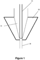
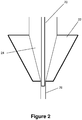
Figures 1-2 are schematic views of a catheter hub in accordance with the present invention; -
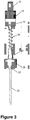
Figure 3 is a plan view of a delivery adapter according to one embodiment of the present invention; -
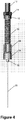
Figure 4 is a plan view of a delivery adapter according to another embodiment of the present invention; -
Figure 5 is a perspective view of the delivery adapter ofFigure 4 . -
Figure 6 is a plan view of a delivery adapter according a further embodiment of the present invention. -
Figure 7A depict a further embodiment of a delivery adapter according to the present invention. -
Figure 7B illustrates a cross-sectional view of a thread configuration of the embodiment ofFigure 7A . - For the description below the terms proximal and distal are used in regards to particular Figures. Please note generally the term proximal refers to items at the top part of the Figures and the term distal refers to items at the bottom part. The delivery adapter described is connected to a syringe at the top or proximal end, and to a catheter hub at the bottom or distal end. The delivery adapter, when oriented for delivery, may not necessarily sit in a vertical, top-down manner as shown in most of the figures (i.e. adapter may sit laterally, left-to-right or right-to-left depending on the delivery configuration).
- Liquid embolic is generally delivered from a syringe to a catheter and then from the catheter to a location within the vasculature of a patient. The embolic material flows through the syringe, into the catheter hub, where the
hub 22 includes atapered reservoir 24 which leads into asmaller diameter channel 26 and the rest of the catheter (seeFigure 1 ). - Due to the tapered shape of the
reservoir 24, it is possible for saline or DMSO or other fluids to remain in the reservoir after those liquids have been used to flush thecatheter reservoir 24 andhub 22. When liquid embolic is subsequently delivered, the remaining flushing liquid (e.g., saline or DMSO) may mix with the liquid embolic, thereby diluting the liquid embolic. An adapter provides an interface to deliver the liquid embolic from the syringe to the catheter while minimizing contact with the catheter hub reservoir and thereby minimize or even eliminate any dilution of the liquid embolic by the flushing liquid. - The adapter includes a
micro-tube 20 through which the liquid embolic is delivered and which sits within the catheter hub. InFigure 1 the micro-tube 20 sits in the distal part of thecatheter reservoir 24, thus minimizing potential mixing with any flushing fluid retained in thereservoir 24. - In
Figure 2 , themicro-tube 20 bypasses the reservoir entirely and sits within thesmaller diameter channel 26. The adapter described may adopt either configuration within thecatheter hub 22 shown inFigures 1-2 , based on the size of thereservoir 24 and length of themicro-tube 20. -
Figure 3 shows an embodiment of a delivery adapter comprising aproximal connector 12,distal connector 28, micro-tube 20, andbridging piece 30 which sits between the proximal anddistal connectors proximal connector 12 may be made of a polymer and may include amating section 10 in the form of a male luer which connects with the female connector of a syringe. Theproximal connector 12 may also include a roughedsection 14 to aid the user in gripping the adapter to screw and unscrew said adapter from the syringe. In one example the micro-tube 20 is recessed and captured within a portion of theproximal connector 12. In one example theproximal connector 12 contains a channel in which the micro-tube sits. Themicro-tube 20 runs from theproximal connector 12 pastdistal connector 28. Bridgingpiece 30 sits betweenproximal connector 12 anddistal connector 28. - In the embodiment shown in
Figure 3 , thebridging piece 30 is shown as a spring which can be made of a metallic material. In one example,distal connector 28 may be made of a polymer.Distal connector 28 may include achannel 32 which runs through saidconnector 28. Micro-tube 20 runs throughchannel 32. In one example, thebridging piece 30 is glued withinproximal connector 12 and sits within channels indistal connector 28. This configuration would enable rotation of the bridging piece 30 (e.g., a spring) when thedistal connector 28 is not connected to the catheter hub and the user torquesproximal connector 12. In one example, the distal end ofmicro-tube 20 extends about 5-40 mm pastdistal connector 28. In another example, the distal end ofmicro-tube 20 extends about 10-20 mm pastdistal connector 28. In another example, the distal end ofmicro-tube 20 extends about 15 mm pastdistal connector 28. The syringe, when mated toproximal connector 12 viamating section 10, connects directly to micro-tube 20 which sits within theproximal connector 12. Thus the syringe contents are directly transferred into the micro-tube of the adapter, and out the distal end of themicro-tube 20 into the catheter hub when the catheter hub is connected todistal connector 28. -
Figures 4-5 show another embodiment of a delivery adapter showing an additional distal rotatingelement 34 which sits just distal ofdistal connector 28. In one example,bridging piece 30 is glued into proximal connector 12 (e.g., via UV glue) and glued intodistal connector 28. Any torquing of theproximal connector 12 by the user prior to attaching the adapter to the catheter hub will result in twisting ofdistal connector 28. In one embodiment, distal rotatingelement 34 is free to rotate independent of and/or relative todistal connector 28. The rotational capability ofelement 34 eases some of the stress onspring bridging element 30 that can otherwise be caused by unilateral torsional stress which may build up on one part of the spring/bridging element, particularly after the adapter is secured to the catheter hub. - Micro-tube 20 may be comprised of a polymer in one example, or a metallic material in another example.
- Another embodiment could utilize a threaded
bridging piece 30 instead of thespring bridging piece 30 shown inFigures 3-5 . The threadedbridging piece 30 could be formed of a metallic or polymeric material and would have threads on the surface. - In one example the
bridging piece 30 has external projecting threads anddistal connector 28 has corresponding recesses to mate with said threads as shown inFig. 6 , thus rotation of thedistal connector 28 will cause upwards or downwards (proximal or distal) movement ofdistal connector 28. In another example thebridging piece 30 has internal recesses anddistal connector 28 has corresponding threads to mate with said recesses, thus rotation of thedistal connector 28 will cause upwards or downwards - (proximal or distal) movement of
distal connector 28. For the embodiment shown inFigures 4-5 , eitherdistal connector 28 or distalrotating element 34 may have the threads or recesses to mate with the bridgingelement 30. Alternatively, for the embodiment shown inFigures 4-5 , bothdistal connector 28 and distalrotating element 34 may have the threads or recesses to mate with the bridgingelement 30. - The
micro-tube 20 of the embodiments shown inFigures 3-5 may terminate within thecatheter reservoir 24 or may bypass thecatheter reservoir 24 entirely. In one example the distal end ofmicro-tube 20 extends about 5-40 mm pastdistal connector 28. In another example the distal end ofmicro-tube 20 extends about 10-20 mm pastdistal connector 28. In another example the distal end ofmicro-tube 20 extends about 15 mm pastdistal connector 28. - Different catheters have different hub and reservoir sizes. The embodiments shown in
Figures 3-7 can be thought of as a universal adapter since the micro-tube length does not have to be customized to fit various catheter hubs.Micro-tube 20 is placed as distally as possible within thecatheter hub 22.Distal connector 28 and/or distalrotating element 34 is then pulled (spring bridging piece embodiment) or rotated (threaded bridging piece embodiment) so distal connector 28 (Figure 3 embodiment) or distal rotating element 34 (Figures 4-6 embodiment) mates to the catheter hub. When pulled/rotated into this position, the rotatingelement 34 or distal connector 28 (depending on the embodiment) is then screwed over the catheter hub to secure the connection. - A method of using the universal delivery adapter of
Figures 3-6 for delivery of a high viscosity liquid (e.g., a liquid embolic) is as follows: The catheter, microcatheter, or delivery device is flushed with saline and navigated to the target site. The catheter is flushed with solvent (e.g., a biocompatible solvent such as DMSO/dimethyl sulfoxide). Thecatheter hub 22 is filled with solvent (DMSO) in order to remove air bubbles and minimize chances of air bubble formation. Theproximal connector 12 of the delivery adapter is connected to the syringe, and liquid embolic is injected through the delivery adapter to purge the delivery adapter of air. Once purged, the micro-tube 20 is placed within thecatheter hub 22. Once the micro-tube 20 is placed within thecatheter hub 22, the distal connector 28 (Figure 3 embodiment) and/or distal rotating element 34 (Figures 4-6 embodiments) is pulled (spring bridging piece 30) or rotated (threaded bridging piece 30) to connect to the catheter. When pulled/rotated into this position, the rotatingelement 34 or distal connector 28 (depending on the embodiment) is then screwed over the catheter hub to secure the connection. Liquid embolic may then be delivered from the syringe, via the delivery adapter, to the target treatment site via the catheter once the catheter is navigated to the target treatment site. - Referring to
Figs. 7A-7B , an additional embodiment of the adapter is shown.Proximal connector 12 mates with threadedbridging piece 30 viaexternal threads 30A on the bridging piece andinternal threads 30B on theproximal connector 12. However, the mating surfaces of thethreads proximal connector 12 will cause the walls of theproximal connector 12 to expand and to disengage thethreads 30A/30B. This allows axial movement (either up or down) of theproximal connector 12 relative to the threadedbridging piece 30 in a ratchet-type action. Once the threshold axial force is removed, the walls of theproximal connector 12 will return to a normal position and thethreads threads 30A/30B are ramped as illustrated inFig. 7B . - In one embodiment, the
proximal connector 12 is configured such that the user can squeeze together the outer top edges of theproximal connector 12 and thereby force the lower edges of the proximal connector to flex outwardly. This results in the disengagement of thethreads proximal connector 12 up and down freely. Once the desired position is reached, the user releases outer top edges of theproximal connector 12 and the lower edges of theproximal connector 12 return to the unflexed state and therebythreads 30A/30B reengage. Theproximal connector 12 may adopt a slightly concave shape in this embodiment to enable such flexing in response to this squeezing pressure. In one example, a grasping portion (i.e. a roughened portion for the user to grip) can be included on theproximal connector 12 where the user would squeeze to initiate the flexing in order to freely moveproximal connector 12. - Continuing to refer to
Figs 7A, 7B , in use, the user determines the desired distance for themicrotube 20 to extend beyond thedistal connector 28. The user then exerts an axial force on theproximal connector 12 in the manner described above to move theproximal connector 12 and its attached microtube 20 to the aforesaid distance. The user can "fine tune" the desired distance through rotation of theproximal connector 12 relative to the threadedbridge piece 30. The adapter is then ready for inserting themicrotube 20 into the catheter hub. The user then fastens the catheter to the adapter via screwing thedistal connector 28 onto the catheter hub (e.g., via a luer lock connection). The user also attaches the syringe to theluer lock 10 at the top of theproximal connector 12. - Although the invention has been described in terms of particular embodiments and applications, one of ordinary skill in the art, in light of this teaching, can generate additional embodiments and modifications without departing from or exceeding the scope of the claimed invention. Accordingly, it is to be understood that the drawings and descriptions herein are proffered by way of example to facilitate comprehension of the invention and should not be construed to limit the scope thereof.
The scope of the claimed invention is defined by the independent claims.
Claims (15)
- An adapter comprising:a first connector adapted for connection to a syringe;a second connector independent of the first connector adapted for connection to a catheter hub (22);a bridging piece (30) disposed between and connecting the first connector (12) and the second connector (28);the first connector being a proximal connector,the second connector being a distal connector (28); characterized bya tube (20) connected to and extending from the proximal connector through and past the distal connector (28); whereinsaid bridging piece is configured to allow adjustment of a position of the distal connector (28) relative to and over the tube (20) and between the proximal connector and the distal connector.
- The adapter of claim 1, wherein the bridging piece (30) comprises a spring.
- The adapter of claim 1, wherein the bridging piece (30) comprises threads.
- The adapter of claim 1, wherein said tube (20) of said adapter extends beyond said distal connector (28) so as to bypass a reservoir of the catheter hub (22) when said distal connector (28) is connected to the catheter hub (22).
- The adapter of claim 1, wherein an end of said tube (20) of said adapter extends beyond said distal connector (28) such that said end of said tube (20) resides within a reservoir of the catheter hub (22) when said distal connector (28) is connected to the catheter hub (22).
- The adapter of claim 1, wherein said distal connector (28) independently rotates relative to the proximal connector (12).
- A method of adapting a syringe to a catheter by means of the adapter as defined in any of the preceding claims comprising the steps of:connecting the proximal connector (12) of the adapter to a syringe;inserting the tubular member (20) of said adapter that is connected to the proximal connector (12) and that extends distally beyond the distal connector (28) of said adaptor within a catheter hub (22);moving the distal connector (28) of said adapter relative to and over said tubular member (20); andsecuring said distal connector (28) of said adapter to said catheter hub(22).
- The method of claim 7, wherein inserting the tubular member (20) of said adapter within the catheter hub (22) comprises bypassing a reservoir of said catheter hub with the tubular member.
- The method of claim 7, wherein inserting the tubular member (20) of said adapter that is connected to the proximal connector (12) and that extends distally beyond the distal connector of said adaptor within the catheter hub (22) comprises disposing an end of the tubular member within a reservoir of said catheter hub.
- An embolic delivery system comprising the adapter of claim 1 and a syringe containing an embolic material.
- The embolic delivery system of claim 10, wherein the bridging piece (30) comprises a spring.
- The embolic delivery system of claim 10, wherein said bridging piece (30) comprises helical threads.
- The embolic delivery system of claim 10, wherein said distal connector (28) is independently rotatable relative to the proximal connector (12).
- The embolic delivery system of claim 10, wherein said tube (20) extends beyond said distal connector (28) so as to bypass a reservoir of the catheter hub (22) when said distal connector (28) is connected to the catheter hub (22).
- The embolic delivery system of claim 10, wherein the said tube (20) of said adapter extends beyond said distal connector (20) such that an end of said tube (20) resides within a reservoir of the catheter hub (22) when said distal connector (28) is connected to the catheter hub (22).
Applications Claiming Priority (2)
| Application Number | Priority Date | Filing Date | Title |
|---|---|---|---|
| US201361919664P | 2013-12-20 | 2013-12-20 | |
| PCT/US2014/071711 WO2015095815A1 (en) | 2013-12-20 | 2014-12-19 | Delivery adapter |
Publications (3)
| Publication Number | Publication Date |
|---|---|
| EP3082939A1 EP3082939A1 (en) | 2016-10-26 |
| EP3082939A4 EP3082939A4 (en) | 2017-08-16 |
| EP3082939B1 true EP3082939B1 (en) | 2020-12-02 |
Family
ID=53398945
Family Applications (1)
| Application Number | Title | Priority Date | Filing Date |
|---|---|---|---|
| EP14871442.1A Active EP3082939B1 (en) | 2013-12-20 | 2014-12-19 | Delivery adapter |
Country Status (5)
| Country | Link |
|---|---|
| US (3) | US9833604B2 (en) |
| EP (1) | EP3082939B1 (en) |
| JP (2) | JP6412137B2 (en) |
| CN (1) | CN106029157B (en) |
| WO (1) | WO2015095815A1 (en) |
Families Citing this family (124)
| Publication number | Priority date | Publication date | Assignee | Title |
|---|---|---|---|---|
| WO2007047851A2 (en) | 2005-10-19 | 2007-04-26 | Pulsar Vascular, Inc. | Methods and systems for endovascularly clipping and repairing lumen and tissue defects |
| US9402707B2 (en) | 2008-07-22 | 2016-08-02 | Neuravi Limited | Clot capture systems and associated methods |
| WO2010028314A1 (en) | 2008-09-05 | 2010-03-11 | Pulsar Vascular, Inc. | Systems and methods for supporting or occluding a physiological opening or cavity |
| US9463036B2 (en) | 2010-10-22 | 2016-10-11 | Neuravi Limited | Clot engagement and removal system |
| US11259824B2 (en) | 2011-03-09 | 2022-03-01 | Neuravi Limited | Clot retrieval device for removing occlusive clot from a blood vessel |
| US9301769B2 (en) | 2011-03-09 | 2016-04-05 | Neuravi Limited | Clot retrieval device for removing clot from a blood vessel |
| WO2012167156A1 (en) | 2011-06-03 | 2012-12-06 | Pulsar Vascular, Inc. | Aneurysm devices with additional anchoring mechanisms and associated systems and methods |
| EP3735916A1 (en) | 2011-10-05 | 2020-11-11 | Pulsar Vascular, Inc. | Devices for enclosing an anatomical opening |
| US10561509B2 (en) | 2013-03-13 | 2020-02-18 | DePuy Synthes Products, Inc. | Braided stent with expansion ring and method of delivery |
| US10603157B2 (en) | 2013-03-13 | 2020-03-31 | DePuy Synthes Products, Inc. | Braid implant delivery and retraction device with distal engagement |
| US9433429B2 (en) | 2013-03-14 | 2016-09-06 | Neuravi Limited | Clot retrieval devices |
| EP2967611B1 (en) | 2013-03-14 | 2019-01-16 | Neuravi Limited | Devices for removal of acute blockages from blood vessels |
| CN109157304B (en) | 2013-03-14 | 2021-12-31 | 尼尔拉维有限公司 | A clot retrieval device for removing a clogged clot from a blood vessel |
| US9833604B2 (en) * | 2013-12-20 | 2017-12-05 | Microvention, Inc. | Delivery adapter |
| US10285720B2 (en) | 2014-03-11 | 2019-05-14 | Neuravi Limited | Clot retrieval system for removing occlusive clot from a blood vessel |
| US11076860B2 (en) | 2014-03-31 | 2021-08-03 | DePuy Synthes Products, Inc. | Aneurysm occlusion device |
| US11154302B2 (en) | 2014-03-31 | 2021-10-26 | DePuy Synthes Products, Inc. | Aneurysm occlusion device |
| US10441301B2 (en) | 2014-06-13 | 2019-10-15 | Neuravi Limited | Devices and methods for removal of acute blockages from blood vessels |
| US10265086B2 (en) | 2014-06-30 | 2019-04-23 | Neuravi Limited | System for removing a clot from a blood vessel |
| US9918718B2 (en) | 2014-08-08 | 2018-03-20 | DePuy Synthes Products, Inc. | Embolic coil delivery system with retractable mechanical release mechanism |
| US10206796B2 (en) | 2014-08-27 | 2019-02-19 | DePuy Synthes Products, Inc. | Multi-strand implant with enhanced radiopacity |
| US9782178B2 (en) | 2014-09-19 | 2017-10-10 | DePuy Synthes Products, Inc. | Vasculature occlusion device detachment system with tapered corewire and heater activated fiber detachment |
| EP3223723B1 (en) | 2014-11-26 | 2020-01-08 | Neuravi Limited | A clot retrieval device for removing occlusive clot from a blood vessel |
| US11253278B2 (en) | 2014-11-26 | 2022-02-22 | Neuravi Limited | Clot retrieval system for removing occlusive clot from a blood vessel |
| US10617435B2 (en) | 2014-11-26 | 2020-04-14 | Neuravi Limited | Clot retrieval device for removing clot from a blood vessel |
| US10285710B2 (en) | 2016-06-01 | 2019-05-14 | DePuy Synthes Products, Inc. | Endovascular detachment system with flexible distal end and heater activated detachment |
| CN109862835B (en) | 2016-08-17 | 2022-09-13 | 尼尔拉维有限公司 | Clot retrieval system for removing an occluded clot from a blood vessel |
| US10076428B2 (en) | 2016-08-25 | 2018-09-18 | DePuy Synthes Products, Inc. | Expansion ring for a braided stent |
| AU2017324233A1 (en) | 2016-09-06 | 2019-04-04 | Neuravi Limited | A clot retrieval device for removing occlusive clot from a blood vessel |
| US10292851B2 (en) | 2016-09-30 | 2019-05-21 | DePuy Synthes Products, Inc. | Self-expanding device delivery apparatus with dual function bump |
| US10517708B2 (en) | 2016-10-26 | 2019-12-31 | DePuy Synthes Products, Inc. | Multi-basket clot capturing device |
| US10905853B2 (en) | 2017-01-17 | 2021-02-02 | DePuy Synthes Products, Inc. | System and method for delivering a catheter |
| US10881497B2 (en) | 2017-01-26 | 2021-01-05 | DePuy Synthes Products, Inc. | Composite vascular flow diverter |
| EP3576810B1 (en) * | 2017-02-06 | 2023-11-29 | Microvention, Inc. | Delivery adapter |
| MX2019010041A (en) | 2017-02-23 | 2020-01-13 | Depuy Synthes Products Inc | Aneurysm device and delivery system. |
| US10806462B2 (en) | 2017-12-21 | 2020-10-20 | DePuy Synthes Products, Inc. | Implantable medical device detachment system with split tube and cylindrical coupling |
| US10751065B2 (en) | 2017-12-22 | 2020-08-25 | DePuy Synthes Products, Inc. | Aneurysm device and delivery system |
| US10905430B2 (en) | 2018-01-24 | 2021-02-02 | DePuy Synthes Products, Inc. | Aneurysm device and delivery system |
| US10786259B2 (en) | 2018-03-30 | 2020-09-29 | DePuy Synthes Products, Inc. | Split balloon assist device and method for using the same |
| US10918390B2 (en) | 2018-03-30 | 2021-02-16 | DePuy Synthes Products, Inc. | Helical balloon assist device and method for using the same |
| US10806461B2 (en) | 2018-04-27 | 2020-10-20 | DePuy Synthes Products, Inc. | Implantable medical device detachment system with split tube |
| US11058430B2 (en) | 2018-05-25 | 2021-07-13 | DePuy Synthes Products, Inc. | Aneurysm device and delivery system |
| US11596412B2 (en) | 2018-05-25 | 2023-03-07 | DePuy Synthes Products, Inc. | Aneurysm device and delivery system |
| US10939915B2 (en) | 2018-05-31 | 2021-03-09 | DePuy Synthes Products, Inc. | Aneurysm device and delivery system |
| US10667833B2 (en) | 2018-06-08 | 2020-06-02 | Neuravi Limited | Guidewire with an atraumatic clot-circumventing configured distal end for use in an endovascular medical system |
| US10898216B2 (en) | 2018-06-13 | 2021-01-26 | DePuy Synthes Products, Inc. | Vasculature obstruction capture device |
| AU2019204522A1 (en) | 2018-07-30 | 2020-02-13 | DePuy Synthes Products, Inc. | Systems and methods of manufacturing and using an expansion ring |
| US10905431B2 (en) | 2018-08-03 | 2021-02-02 | DePuy Synthes Products, Inc. | Spiral delivery system for embolic braid |
| US10278848B1 (en) | 2018-08-06 | 2019-05-07 | DePuy Synthes Products, Inc. | Stent delivery with expansion assisting delivery wire |
| US10456280B1 (en) | 2018-08-06 | 2019-10-29 | DePuy Synthes Products, Inc. | Systems and methods of using a braided implant |
| US11051825B2 (en) | 2018-08-08 | 2021-07-06 | DePuy Synthes Products, Inc. | Delivery system for embolic braid |
| US10813780B2 (en) | 2018-08-08 | 2020-10-27 | DePuy Synthes Products, Inc. | Intraluminal implant delivery system and method |
| US10842498B2 (en) | 2018-09-13 | 2020-11-24 | Neuravi Limited | Systems and methods of restoring perfusion to a vessel |
| BR102019019522A2 (en) | 2018-09-20 | 2020-04-07 | Depuy Synthes Products Inc | stent with conformed wires |
| US11123077B2 (en) | 2018-09-25 | 2021-09-21 | DePuy Synthes Products, Inc. | Intrasaccular device positioning and deployment system |
| US11406416B2 (en) | 2018-10-02 | 2022-08-09 | Neuravi Limited | Joint assembly for vasculature obstruction capture device |
| US11253287B2 (en) | 2018-10-04 | 2022-02-22 | Neuravi Limited | Retrograde blood flow occlusion flushing device |
| US11076861B2 (en) | 2018-10-12 | 2021-08-03 | DePuy Synthes Products, Inc. | Folded aneurysm treatment device and delivery method |
| US11406392B2 (en) | 2018-12-12 | 2022-08-09 | DePuy Synthes Products, Inc. | Aneurysm occluding device for use with coagulating agents |
| US11147562B2 (en) | 2018-12-12 | 2021-10-19 | DePuy Synthes Products, Inc. | Systems and methods for embolic implant detachment |
| US11272939B2 (en) | 2018-12-18 | 2022-03-15 | DePuy Synthes Products, Inc. | Intrasaccular flow diverter for treating cerebral aneurysms |
| US11039944B2 (en) | 2018-12-27 | 2021-06-22 | DePuy Synthes Products, Inc. | Braided stent system with one or more expansion rings |
| US11134953B2 (en) | 2019-02-06 | 2021-10-05 | DePuy Synthes Products, Inc. | Adhesive cover occluding device for aneurysm treatment |
| US11273285B2 (en) | 2019-02-07 | 2022-03-15 | DePuy Synthes Products, Inc. | Ancillary device for detaching implants |
| EP3705066B1 (en) | 2019-03-04 | 2021-12-29 | Neuravi Limited | Actuated clot retrieval catheter |
| US11382633B2 (en) | 2019-03-06 | 2022-07-12 | DePuy Synthes Products, Inc. | Strut flow diverter for cerebral aneurysms and methods for preventing strut entanglement |
| US11337706B2 (en) | 2019-03-27 | 2022-05-24 | DePuy Synthes Products, Inc. | Aneurysm treatment device |
| US11185334B2 (en) | 2019-03-28 | 2021-11-30 | DePuy Synthes Products, Inc. | Single lumen reduced profile occlusion balloon catheter |
| US11051928B2 (en) | 2019-04-11 | 2021-07-06 | Neuravi Limited | Floating carotid filter |
| US11571553B2 (en) | 2019-05-09 | 2023-02-07 | Neuravi Limited | Balloon guide catheter with thermally expandable material |
| US11607531B2 (en) | 2019-05-09 | 2023-03-21 | Neuravi Limited | Balloon catheter with venting of residual air in a proximal direction |
| US11931522B2 (en) | 2019-05-09 | 2024-03-19 | Neuravi Limited | Inflation lumen kink protection and balloon profile |
| USD959659S1 (en) | 2019-05-10 | 2022-08-02 | DePuy Synthes Products, Inc. | Implant release handle |
| US11672542B2 (en) | 2019-05-21 | 2023-06-13 | DePuy Synthes Products, Inc. | Aneurysm treatment with pushable ball segment |
| US11413046B2 (en) | 2019-05-21 | 2022-08-16 | DePuy Synthes Products, Inc. | Layered braided aneurysm treatment device |
| US11497504B2 (en) | 2019-05-21 | 2022-11-15 | DePuy Synthes Products, Inc. | Aneurysm treatment with pushable implanted braid |
| US11607226B2 (en) | 2019-05-21 | 2023-03-21 | DePuy Synthes Products, Inc. | Layered braided aneurysm treatment device with corrugations |
| US11602350B2 (en) | 2019-12-05 | 2023-03-14 | DePuy Synthes Products, Inc. | Intrasaccular inverting braid with highly flexible fill material |
| US10653425B1 (en) | 2019-05-21 | 2020-05-19 | DePuy Synthes Products, Inc. | Layered braided aneurysm treatment device |
| US11278292B2 (en) | 2019-05-21 | 2022-03-22 | DePuy Synthes Products, Inc. | Inverting braided aneurysm treatment system and method |
| US11109939B2 (en) | 2019-06-14 | 2021-09-07 | DePuy Synthes Products, Inc. | Intravascular devices with radiopaque body markers |
| US11406403B2 (en) | 2019-06-14 | 2022-08-09 | Neuravi Limited | Visibility of mechanical thrombectomy device during diagnostic imaging |
| US11253265B2 (en) | 2019-06-18 | 2022-02-22 | DePuy Synthes Products, Inc. | Pull wire detachment for intravascular devices |
| US11207494B2 (en) | 2019-07-03 | 2021-12-28 | DePuy Synthes Products, Inc. | Medical device delivery member with flexible stretch resistant distal portion |
| US11426174B2 (en) | 2019-10-03 | 2022-08-30 | DePuy Synthes Products, Inc. | Medical device delivery member with flexible stretch resistant mechanical release |
| US11266427B2 (en) | 2019-07-10 | 2022-03-08 | Neuravi Limited | Self-expanding intravascular medical device |
| US11266426B2 (en) | 2019-07-10 | 2022-03-08 | DePuy Synthes Products, Inc. | Streamlined treatment of clot removal, angioplasty and prevention of restenosis using a single integrated intravascular device |
| US11395675B2 (en) | 2019-07-11 | 2022-07-26 | DePuy Synthes Products, Inc. | Clot retriever cleaning for reinsertion |
| JP2021041169A (en) | 2019-09-11 | 2021-03-18 | ニューラヴィ・リミテッド | Expandable mouth catheter |
| US11439403B2 (en) | 2019-09-17 | 2022-09-13 | DePuy Synthes Products, Inc. | Embolic coil proximal connecting element and stretch resistant fiber |
| US11712231B2 (en) | 2019-10-29 | 2023-08-01 | Neuravi Limited | Proximal locking assembly design for dual stent mechanical thrombectomy device |
| US11376013B2 (en) | 2019-11-18 | 2022-07-05 | DePuy Synthes Products, Inc. | Implant delivery system with braid cup formation |
| US11628282B2 (en) | 2019-11-25 | 2023-04-18 | Neuravi Limited | No preparation balloon guide catheter |
| US11839725B2 (en) | 2019-11-27 | 2023-12-12 | Neuravi Limited | Clot retrieval device with outer sheath and inner catheter |
| US11779364B2 (en) | 2019-11-27 | 2023-10-10 | Neuravi Limited | Actuated expandable mouth thrombectomy catheter |
| US11517340B2 (en) | 2019-12-03 | 2022-12-06 | Neuravi Limited | Stentriever devices for removing an occlusive clot from a vessel and methods thereof |
| US11457926B2 (en) | 2019-12-18 | 2022-10-04 | DePuy Synthes Products, Inc. | Implant having an intrasaccular section and intravascular section |
| CN111134756B (en) * | 2019-12-30 | 2021-01-19 | 西安交通大学 | Fibrous chronic embolism device for preventing ectopic embolism |
| US11457922B2 (en) | 2020-01-22 | 2022-10-04 | DePuy Synthes Products, Inc. | Medical device delivery member with flexible stretch resistant distal portion |
| US11432822B2 (en) | 2020-02-14 | 2022-09-06 | DePuy Synthes Products, Inc. | Intravascular implant deployment system |
| US11944327B2 (en) | 2020-03-05 | 2024-04-02 | Neuravi Limited | Expandable mouth aspirating clot retrieval catheter |
| US11633198B2 (en) | 2020-03-05 | 2023-04-25 | Neuravi Limited | Catheter proximal joint |
| US11883043B2 (en) | 2020-03-31 | 2024-01-30 | DePuy Synthes Products, Inc. | Catheter funnel extension |
| US11759217B2 (en) | 2020-04-07 | 2023-09-19 | Neuravi Limited | Catheter tubular support |
| US11717308B2 (en) | 2020-04-17 | 2023-08-08 | Neuravi Limited | Clot retrieval device for removing heterogeneous clots from a blood vessel |
| US11871946B2 (en) | 2020-04-17 | 2024-01-16 | Neuravi Limited | Clot retrieval device for removing clot from a blood vessel |
| US11730501B2 (en) | 2020-04-17 | 2023-08-22 | Neuravi Limited | Floating clot retrieval device for removing clots from a blood vessel |
| US11523831B2 (en) | 2020-04-30 | 2022-12-13 | DePuy Synthes Products, Inc. | Intrasaccular flow diverter |
| US11737771B2 (en) | 2020-06-18 | 2023-08-29 | Neuravi Limited | Dual channel thrombectomy device |
| US11937836B2 (en) | 2020-06-22 | 2024-03-26 | Neuravi Limited | Clot retrieval system with expandable clot engaging framework |
| US11395669B2 (en) | 2020-06-23 | 2022-07-26 | Neuravi Limited | Clot retrieval device with flexible collapsible frame |
| US11439418B2 (en) | 2020-06-23 | 2022-09-13 | Neuravi Limited | Clot retrieval device for removing clot from a blood vessel |
| US11951026B2 (en) | 2020-06-30 | 2024-04-09 | DePuy Synthes Products, Inc. | Implantable medical device detachment system with flexible braid section |
| US11864781B2 (en) | 2020-09-23 | 2024-01-09 | Neuravi Limited | Rotating frame thrombectomy device |
| US11786698B2 (en) | 2020-12-08 | 2023-10-17 | DePuy Synthes Products, Inc. | Catheter with textured surface |
| US11826520B2 (en) | 2020-12-08 | 2023-11-28 | DePuy Synthes Products, Inc. | Catheter designs for enhanced column strength |
| US11937837B2 (en) | 2020-12-29 | 2024-03-26 | Neuravi Limited | Fibrin rich / soft clot mechanical thrombectomy device |
| US11872354B2 (en) | 2021-02-24 | 2024-01-16 | Neuravi Limited | Flexible catheter shaft frame with seam |
| US11937839B2 (en) | 2021-09-28 | 2024-03-26 | Neuravi Limited | Catheter with electrically actuated expandable mouth |
| US11751881B2 (en) | 2021-11-26 | 2023-09-12 | DePuy Synthes Products, Inc. | Securement wire withstanding forces during deployment of implantable intravascular treatment device using a delivery and detachment system |
| US11937824B2 (en) | 2021-12-30 | 2024-03-26 | DePuy Synthes Products, Inc. | Implant detachment systems with a modified pull wire |
| US11844490B2 (en) | 2021-12-30 | 2023-12-19 | DePuy Synthes Products, Inc. | Suture linkage for inhibiting premature embolic implant deployment |
| US11937825B2 (en) | 2022-03-02 | 2024-03-26 | DePuy Synthes Products, Inc. | Hook wire for preventing premature embolic implant detachment |
| US11937826B2 (en) | 2022-03-14 | 2024-03-26 | DePuy Synthes Products, Inc. | Proximal link wire for preventing premature implant detachment |
Family Cites Families (10)
| Publication number | Priority date | Publication date | Assignee | Title |
|---|---|---|---|---|
| US4187848A (en) * | 1977-07-18 | 1980-02-12 | The Kendall Company | Adapter assembly |
| JP2923298B2 (en) * | 1989-02-06 | 1999-07-26 | テルモ株式会社 | Medical guidewire |
| US5122123A (en) * | 1991-01-30 | 1992-06-16 | Vaillancourt Vincent L | Closed system connector assembly |
| US5509911A (en) * | 1992-11-27 | 1996-04-23 | Maxxim Medical, Inc. | Rotating adapter for a catheterization system |
| CA2361129A1 (en) * | 1999-05-21 | 2000-11-30 | Douglas R. Hayman | Interface needle and method for creating a blunt interface between delivered liquids |
| JP2001170187A (en) * | 1999-12-17 | 2001-06-26 | Terumo Corp | Connector |
| US7195615B2 (en) * | 2003-05-14 | 2007-03-27 | Boston Scientific Scimed, Inc. | System for providing a medical device with anti-microbial properties |
| WO2009045793A1 (en) * | 2007-09-28 | 2009-04-09 | Access Closure, Inc. | Apparatus and methods for sealing a vascular puncture |
| US9414990B2 (en) * | 2013-03-15 | 2016-08-16 | Becton Dickinson and Company Ltd. | Seal system for cannula |
| US9833604B2 (en) * | 2013-12-20 | 2017-12-05 | Microvention, Inc. | Delivery adapter |
-
2014
- 2014-12-19 US US14/578,164 patent/US9833604B2/en active Active
- 2014-12-19 CN CN201480076090.0A patent/CN106029157B/en active Active
- 2014-12-19 WO PCT/US2014/071711 patent/WO2015095815A1/en active Application Filing
- 2014-12-19 EP EP14871442.1A patent/EP3082939B1/en active Active
- 2014-12-19 JP JP2016541572A patent/JP6412137B2/en active Active
-
2017
- 2017-11-03 US US15/803,694 patent/US10668264B2/en active Active
-
2018
- 2018-09-27 JP JP2018183008A patent/JP6577111B2/en active Active
-
2020
- 2020-04-23 US US16/856,727 patent/US11666742B2/en active Active
Non-Patent Citations (1)
| Title |
|---|
| None * |
Also Published As
| Publication number | Publication date |
|---|---|
| JP6577111B2 (en) | 2019-09-18 |
| US9833604B2 (en) | 2017-12-05 |
| CN106029157B (en) | 2019-09-17 |
| EP3082939A4 (en) | 2017-08-16 |
| CN106029157A (en) | 2016-10-12 |
| US20150174389A1 (en) | 2015-06-25 |
| US11666742B2 (en) | 2023-06-06 |
| WO2015095815A1 (en) | 2015-06-25 |
| JP2019048065A (en) | 2019-03-28 |
| EP3082939A1 (en) | 2016-10-26 |
| JP2017503574A (en) | 2017-02-02 |
| US20180064922A1 (en) | 2018-03-08 |
| JP6412137B2 (en) | 2018-10-24 |
| US20200246607A1 (en) | 2020-08-06 |
| US10668264B2 (en) | 2020-06-02 |
Similar Documents
| Publication | Publication Date | Title |
|---|---|---|
| US11666742B2 (en) | Delivery adapter | |
| EP2174687B1 (en) | Luer lock adapter | |
| KR101800984B1 (en) | Double male connector | |
| RU2668110C2 (en) | Fluid transfer connector | |
| US9861752B2 (en) | Mixing nozzle | |
| CN102548587A (en) | Medical implement cleaning device with friction-based fitting | |
| CA3054003C (en) | Adaptor for connecting a connector to a drug delivery device | |
| JP2013505755A (en) | Medical tube connection device | |
| JP6807835B2 (en) | Drug delivery device with coated end piece | |
| US20220362538A1 (en) | Delivery Adapter | |
| JP6709073B2 (en) | Medical connector | |
| CN104822413B (en) | For giving product to the component of the medical usage of patient | |
| JP2010137043A (en) | Male connector, enteral feeding set, and enteral feeding extension tube | |
| US20190175824A1 (en) | Portable liquid drug delivery device | |
| CN116889657A (en) | intravenous prefilled cap | |
| WO2012122189A2 (en) | Retractable syringe with conical frustum tip |
Legal Events
| Date | Code | Title | Description |
|---|---|---|---|
| PUAI | Public reference made under article 153(3) epc to a published international application that has entered the european phase |
Free format text: ORIGINAL CODE: 0009012 |
|
| 17P | Request for examination filed |
Effective date: 20160617 |
|
| AK | Designated contracting states |
Kind code of ref document: A1 Designated state(s): AL AT BE BG CH CY CZ DE DK EE ES FI FR GB GR HR HU IE IS IT LI LT LU LV MC MK MT NL NO PL PT RO RS SE SI SK SM TR |
|
| AX | Request for extension of the european patent |
Extension state: BA ME |
|
| DAX | Request for extension of the european patent (deleted) | ||
| A4 | Supplementary search report drawn up and despatched |
Effective date: 20170717 |
|
| RIC1 | Information provided on ipc code assigned before grant |
Ipc: A61M 39/10 20060101AFI20170711BHEP |
|
| STAA | Information on the status of an ep patent application or granted ep patent |
Free format text: STATUS: EXAMINATION IS IN PROGRESS |
|
| 17Q | First examination report despatched |
Effective date: 20181106 |
|
| GRAP | Despatch of communication of intention to grant a patent |
Free format text: ORIGINAL CODE: EPIDOSNIGR1 |
|
| STAA | Information on the status of an ep patent application or granted ep patent |
Free format text: STATUS: GRANT OF PATENT IS INTENDED |
|
| INTG | Intention to grant announced |
Effective date: 20200623 |
|
| GRAS | Grant fee paid |
Free format text: ORIGINAL CODE: EPIDOSNIGR3 |
|
| GRAA | (expected) grant |
Free format text: ORIGINAL CODE: 0009210 |
|
| STAA | Information on the status of an ep patent application or granted ep patent |
Free format text: STATUS: THE PATENT HAS BEEN GRANTED |
|
| RAP1 | Party data changed (applicant data changed or rights of an application transferred) |
Owner name: MICROVENTION, INC. |
|
| AK | Designated contracting states |
Kind code of ref document: B1 Designated state(s): AL AT BE BG CH CY CZ DE DK EE ES FI FR GB GR HR HU IE IS IT LI LT LU LV MC MK MT NL NO PL PT RO RS SE SI SK SM TR |
|
| REG | Reference to a national code |
Ref country code: GB Ref legal event code: FG4D |
|
| REG | Reference to a national code |
Ref country code: AT Ref legal event code: REF Ref document number: 1340227 Country of ref document: AT Kind code of ref document: T Effective date: 20201215 Ref country code: CH Ref legal event code: EP |
|
| REG | Reference to a national code |
Ref country code: IE Ref legal event code: FG4D |
|
| REG | Reference to a national code |
Ref country code: DE Ref legal event code: R096 Ref document number: 602014073061 Country of ref document: DE |
|
| PG25 | Lapsed in a contracting state [announced via postgrant information from national office to epo] |
Ref country code: RS Free format text: LAPSE BECAUSE OF FAILURE TO SUBMIT A TRANSLATION OF THE DESCRIPTION OR TO PAY THE FEE WITHIN THE PRESCRIBED TIME-LIMIT Effective date: 20201202 Ref country code: FI Free format text: LAPSE BECAUSE OF FAILURE TO SUBMIT A TRANSLATION OF THE DESCRIPTION OR TO PAY THE FEE WITHIN THE PRESCRIBED TIME-LIMIT Effective date: 20201202 Ref country code: NO Free format text: LAPSE BECAUSE OF FAILURE TO SUBMIT A TRANSLATION OF THE DESCRIPTION OR TO PAY THE FEE WITHIN THE PRESCRIBED TIME-LIMIT Effective date: 20210302 Ref country code: GR Free format text: LAPSE BECAUSE OF FAILURE TO SUBMIT A TRANSLATION OF THE DESCRIPTION OR TO PAY THE FEE WITHIN THE PRESCRIBED TIME-LIMIT Effective date: 20210303 |
|
| REG | Reference to a national code |
Ref country code: NL Ref legal event code: MP Effective date: 20201202 |
|
| REG | Reference to a national code |
Ref country code: AT Ref legal event code: MK05 Ref document number: 1340227 Country of ref document: AT Kind code of ref document: T Effective date: 20201202 |
|
| PG25 | Lapsed in a contracting state [announced via postgrant information from national office to epo] |
Ref country code: BG Free format text: LAPSE BECAUSE OF FAILURE TO SUBMIT A TRANSLATION OF THE DESCRIPTION OR TO PAY THE FEE WITHIN THE PRESCRIBED TIME-LIMIT Effective date: 20210302 Ref country code: LV Free format text: LAPSE BECAUSE OF FAILURE TO SUBMIT A TRANSLATION OF THE DESCRIPTION OR TO PAY THE FEE WITHIN THE PRESCRIBED TIME-LIMIT Effective date: 20201202 Ref country code: SE Free format text: LAPSE BECAUSE OF FAILURE TO SUBMIT A TRANSLATION OF THE DESCRIPTION OR TO PAY THE FEE WITHIN THE PRESCRIBED TIME-LIMIT Effective date: 20201202 Ref country code: PL Free format text: LAPSE BECAUSE OF FAILURE TO SUBMIT A TRANSLATION OF THE DESCRIPTION OR TO PAY THE FEE WITHIN THE PRESCRIBED TIME-LIMIT Effective date: 20201202 |
|
| PG25 | Lapsed in a contracting state [announced via postgrant information from national office to epo] |
Ref country code: NL Free format text: LAPSE BECAUSE OF FAILURE TO SUBMIT A TRANSLATION OF THE DESCRIPTION OR TO PAY THE FEE WITHIN THE PRESCRIBED TIME-LIMIT Effective date: 20201202 Ref country code: HR Free format text: LAPSE BECAUSE OF FAILURE TO SUBMIT A TRANSLATION OF THE DESCRIPTION OR TO PAY THE FEE WITHIN THE PRESCRIBED TIME-LIMIT Effective date: 20201202 |
|
| REG | Reference to a national code |
Ref country code: LT Ref legal event code: MG9D |
|
| PG25 | Lapsed in a contracting state [announced via postgrant information from national office to epo] |
Ref country code: SK Free format text: LAPSE BECAUSE OF FAILURE TO SUBMIT A TRANSLATION OF THE DESCRIPTION OR TO PAY THE FEE WITHIN THE PRESCRIBED TIME-LIMIT Effective date: 20201202 Ref country code: PT Free format text: LAPSE BECAUSE OF FAILURE TO SUBMIT A TRANSLATION OF THE DESCRIPTION OR TO PAY THE FEE WITHIN THE PRESCRIBED TIME-LIMIT Effective date: 20210405 Ref country code: RO Free format text: LAPSE BECAUSE OF FAILURE TO SUBMIT A TRANSLATION OF THE DESCRIPTION OR TO PAY THE FEE WITHIN THE PRESCRIBED TIME-LIMIT Effective date: 20201202 Ref country code: LT Free format text: LAPSE BECAUSE OF FAILURE TO SUBMIT A TRANSLATION OF THE DESCRIPTION OR TO PAY THE FEE WITHIN THE PRESCRIBED TIME-LIMIT Effective date: 20201202 Ref country code: SM Free format text: LAPSE BECAUSE OF FAILURE TO SUBMIT A TRANSLATION OF THE DESCRIPTION OR TO PAY THE FEE WITHIN THE PRESCRIBED TIME-LIMIT Effective date: 20201202 Ref country code: EE Free format text: LAPSE BECAUSE OF FAILURE TO SUBMIT A TRANSLATION OF THE DESCRIPTION OR TO PAY THE FEE WITHIN THE PRESCRIBED TIME-LIMIT Effective date: 20201202 Ref country code: CZ Free format text: LAPSE BECAUSE OF FAILURE TO SUBMIT A TRANSLATION OF THE DESCRIPTION OR TO PAY THE FEE WITHIN THE PRESCRIBED TIME-LIMIT Effective date: 20201202 |
|
| REG | Reference to a national code |
Ref country code: CH Ref legal event code: PL |
|
| PG25 | Lapsed in a contracting state [announced via postgrant information from national office to epo] |
Ref country code: AT Free format text: LAPSE BECAUSE OF FAILURE TO SUBMIT A TRANSLATION OF THE DESCRIPTION OR TO PAY THE FEE WITHIN THE PRESCRIBED TIME-LIMIT Effective date: 20201202 |
|
| REG | Reference to a national code |
Ref country code: DE Ref legal event code: R097 Ref document number: 602014073061 Country of ref document: DE Ref country code: BE Ref legal event code: MM Effective date: 20201231 |
|
| PG25 | Lapsed in a contracting state [announced via postgrant information from national office to epo] |
Ref country code: MC Free format text: LAPSE BECAUSE OF FAILURE TO SUBMIT A TRANSLATION OF THE DESCRIPTION OR TO PAY THE FEE WITHIN THE PRESCRIBED TIME-LIMIT Effective date: 20201202 Ref country code: IS Free format text: LAPSE BECAUSE OF FAILURE TO SUBMIT A TRANSLATION OF THE DESCRIPTION OR TO PAY THE FEE WITHIN THE PRESCRIBED TIME-LIMIT Effective date: 20210402 |
|
| PLBE | No opposition filed within time limit |
Free format text: ORIGINAL CODE: 0009261 |
|
| STAA | Information on the status of an ep patent application or granted ep patent |
Free format text: STATUS: NO OPPOSITION FILED WITHIN TIME LIMIT |
|
| PG25 | Lapsed in a contracting state [announced via postgrant information from national office to epo] |
Ref country code: IT Free format text: LAPSE BECAUSE OF FAILURE TO SUBMIT A TRANSLATION OF THE DESCRIPTION OR TO PAY THE FEE WITHIN THE PRESCRIBED TIME-LIMIT Effective date: 20201202 Ref country code: IE Free format text: LAPSE BECAUSE OF NON-PAYMENT OF DUE FEES Effective date: 20201219 Ref country code: LU Free format text: LAPSE BECAUSE OF NON-PAYMENT OF DUE FEES Effective date: 20201219 Ref country code: AL Free format text: LAPSE BECAUSE OF FAILURE TO SUBMIT A TRANSLATION OF THE DESCRIPTION OR TO PAY THE FEE WITHIN THE PRESCRIBED TIME-LIMIT Effective date: 20201202 |
|
| 26N | No opposition filed |
Effective date: 20210903 |
|
| PG25 | Lapsed in a contracting state [announced via postgrant information from national office to epo] |
Ref country code: LI Free format text: LAPSE BECAUSE OF NON-PAYMENT OF DUE FEES Effective date: 20201231 Ref country code: DK Free format text: LAPSE BECAUSE OF FAILURE TO SUBMIT A TRANSLATION OF THE DESCRIPTION OR TO PAY THE FEE WITHIN THE PRESCRIBED TIME-LIMIT Effective date: 20201202 Ref country code: ES Free format text: LAPSE BECAUSE OF FAILURE TO SUBMIT A TRANSLATION OF THE DESCRIPTION OR TO PAY THE FEE WITHIN THE PRESCRIBED TIME-LIMIT Effective date: 20201202 Ref country code: CH Free format text: LAPSE BECAUSE OF NON-PAYMENT OF DUE FEES Effective date: 20201231 Ref country code: SI Free format text: LAPSE BECAUSE OF FAILURE TO SUBMIT A TRANSLATION OF THE DESCRIPTION OR TO PAY THE FEE WITHIN THE PRESCRIBED TIME-LIMIT Effective date: 20201202 |
|
| PG25 | Lapsed in a contracting state [announced via postgrant information from national office to epo] |
Ref country code: IS Free format text: LAPSE BECAUSE OF FAILURE TO SUBMIT A TRANSLATION OF THE DESCRIPTION OR TO PAY THE FEE WITHIN THE PRESCRIBED TIME-LIMIT Effective date: 20210402 Ref country code: TR Free format text: LAPSE BECAUSE OF FAILURE TO SUBMIT A TRANSLATION OF THE DESCRIPTION OR TO PAY THE FEE WITHIN THE PRESCRIBED TIME-LIMIT Effective date: 20201202 Ref country code: MT Free format text: LAPSE BECAUSE OF FAILURE TO SUBMIT A TRANSLATION OF THE DESCRIPTION OR TO PAY THE FEE WITHIN THE PRESCRIBED TIME-LIMIT Effective date: 20201202 Ref country code: CY Free format text: LAPSE BECAUSE OF FAILURE TO SUBMIT A TRANSLATION OF THE DESCRIPTION OR TO PAY THE FEE WITHIN THE PRESCRIBED TIME-LIMIT Effective date: 20201202 |
|
| PG25 | Lapsed in a contracting state [announced via postgrant information from national office to epo] |
Ref country code: MK Free format text: LAPSE BECAUSE OF FAILURE TO SUBMIT A TRANSLATION OF THE DESCRIPTION OR TO PAY THE FEE WITHIN THE PRESCRIBED TIME-LIMIT Effective date: 20201202 |
|
| PG25 | Lapsed in a contracting state [announced via postgrant information from national office to epo] |
Ref country code: BE Free format text: LAPSE BECAUSE OF NON-PAYMENT OF DUE FEES Effective date: 20201231 |
|
| P01 | Opt-out of the competence of the unified patent court (upc) registered |
Effective date: 20230526 |
|
| PGFP | Annual fee paid to national office [announced via postgrant information from national office to epo] |
Ref country code: GB Payment date: 20231208 Year of fee payment: 10 |
|
| PGFP | Annual fee paid to national office [announced via postgrant information from national office to epo] |
Ref country code: FR Payment date: 20231208 Year of fee payment: 10 Ref country code: DE Payment date: 20231211 Year of fee payment: 10 |