EP2174687B1 - Luer lock adapter - Google Patents
Luer lock adapter Download PDFInfo
- Publication number
- EP2174687B1 EP2174687B1 EP09012835.6A EP09012835A EP2174687B1 EP 2174687 B1 EP2174687 B1 EP 2174687B1 EP 09012835 A EP09012835 A EP 09012835A EP 2174687 B1 EP2174687 B1 EP 2174687B1
- Authority
- EP
- European Patent Office
- Prior art keywords
- adapter
- skirt
- seat
- receptacle
- thread
- Prior art date
- Legal status (The legal status is an assumption and is not a legal conclusion. Google has not performed a legal analysis and makes no representation as to the accuracy of the status listed.)
- Active
Links
- 238000000034 method Methods 0.000 claims description 21
- 239000012530 fluid Substances 0.000 claims description 12
- 238000004891 communication Methods 0.000 claims description 8
- 230000007704 transition Effects 0.000 claims 2
- 239000000463 material Substances 0.000 description 5
- 229920003023 plastic Polymers 0.000 description 4
- 239000004033 plastic Substances 0.000 description 4
- 230000002411 adverse Effects 0.000 description 2
- 230000004075 alteration Effects 0.000 description 2
- 238000005336 cracking Methods 0.000 description 2
- 238000002347 injection Methods 0.000 description 2
- 239000007924 injection Substances 0.000 description 2
- 238000012986 modification Methods 0.000 description 2
- 230000004048 modification Effects 0.000 description 2
- 230000000712 assembly Effects 0.000 description 1
- 238000000429 assembly Methods 0.000 description 1
- 238000005219 brazing Methods 0.000 description 1
- 239000002131 composite material Substances 0.000 description 1
- 238000010276 construction Methods 0.000 description 1
- 229940039231 contrast media Drugs 0.000 description 1
- 239000002872 contrast media Substances 0.000 description 1
- 230000007423 decrease Effects 0.000 description 1
- 238000011161 development Methods 0.000 description 1
- 230000018109 developmental process Effects 0.000 description 1
- 238000003306 harvesting Methods 0.000 description 1
- 239000007788 liquid Substances 0.000 description 1
- 239000002184 metal Substances 0.000 description 1
- 210000000056 organ Anatomy 0.000 description 1
- 238000003825 pressing Methods 0.000 description 1
- 238000009877 rendering Methods 0.000 description 1
- 238000012360 testing method Methods 0.000 description 1
- 230000000007 visual effect Effects 0.000 description 1
- 238000003466 welding Methods 0.000 description 1
Images


Classifications
-
- A—HUMAN NECESSITIES
- A61—MEDICAL OR VETERINARY SCIENCE; HYGIENE
- A61M—DEVICES FOR INTRODUCING MEDIA INTO, OR ONTO, THE BODY; DEVICES FOR TRANSDUCING BODY MEDIA OR FOR TAKING MEDIA FROM THE BODY; DEVICES FOR PRODUCING OR ENDING SLEEP OR STUPOR
- A61M39/00—Tubes, tube connectors, tube couplings, valves, access sites or the like, specially adapted for medical use
- A61M39/10—Tube connectors; Tube couplings
- A61M2039/1044—Verifying the connection, e.g. audible feedback, tactile feedback, visual feedback, using external light sources
-
- A—HUMAN NECESSITIES
- A61—MEDICAL OR VETERINARY SCIENCE; HYGIENE
- A61M—DEVICES FOR INTRODUCING MEDIA INTO, OR ONTO, THE BODY; DEVICES FOR TRANSDUCING BODY MEDIA OR FOR TAKING MEDIA FROM THE BODY; DEVICES FOR PRODUCING OR ENDING SLEEP OR STUPOR
- A61M39/00—Tubes, tube connectors, tube couplings, valves, access sites or the like, specially adapted for medical use
- A61M39/10—Tube connectors; Tube couplings
- A61M2039/1066—Tube connectors; Tube couplings having protection means, e.g. sliding sleeve to protect connector itself, shrouds to protect a needle present in the connector, protective housing, isolating sheath
-
- A—HUMAN NECESSITIES
- A61—MEDICAL OR VETERINARY SCIENCE; HYGIENE
- A61M—DEVICES FOR INTRODUCING MEDIA INTO, OR ONTO, THE BODY; DEVICES FOR TRANSDUCING BODY MEDIA OR FOR TAKING MEDIA FROM THE BODY; DEVICES FOR PRODUCING OR ENDING SLEEP OR STUPOR
- A61M39/00—Tubes, tube connectors, tube couplings, valves, access sites or the like, specially adapted for medical use
- A61M39/10—Tube connectors; Tube couplings
- A61M2039/1077—Adapters, e.g. couplings adapting a connector to one or several other connectors
-
- A—HUMAN NECESSITIES
- A61—MEDICAL OR VETERINARY SCIENCE; HYGIENE
- A61M—DEVICES FOR INTRODUCING MEDIA INTO, OR ONTO, THE BODY; DEVICES FOR TRANSDUCING BODY MEDIA OR FOR TAKING MEDIA FROM THE BODY; DEVICES FOR PRODUCING OR ENDING SLEEP OR STUPOR
- A61M2205/00—General characteristics of the apparatus
- A61M2205/58—Means for facilitating use, e.g. by people with impaired vision
- A61M2205/582—Means for facilitating use, e.g. by people with impaired vision by tactile feedback
-
- A—HUMAN NECESSITIES
- A61—MEDICAL OR VETERINARY SCIENCE; HYGIENE
- A61M—DEVICES FOR INTRODUCING MEDIA INTO, OR ONTO, THE BODY; DEVICES FOR TRANSDUCING BODY MEDIA OR FOR TAKING MEDIA FROM THE BODY; DEVICES FOR PRODUCING OR ENDING SLEEP OR STUPOR
- A61M39/00—Tubes, tube connectors, tube couplings, valves, access sites or the like, specially adapted for medical use
- A61M39/10—Tube connectors; Tube couplings
- A61M39/12—Tube connectors; Tube couplings for joining a flexible tube to a rigid attachment
Definitions
- the invention pertains to medical equipment, and more particularly to an adapter for medical receptacles, and to a method of attaching an adapter to a medical receptacle.
- the document US 2004/0155457 A1 relates to a connecting element comprising a first body with a through-going axial opening situated in the first body for liquid communication between the first end portion of the first end body and the second end portion of the first body, said first end portion comprising a cavity, and wherein the cavity comprises a female part with a through-going opening and manufactured from a first plastics material and comprising an inner area for mounting of a tube by means of first attachment means; and wherein the first body is manufactured from a second plastics material different from the first plastics material.
- the document EP 1 872 824 A1 relates to a luer-locking fitting connection mechanism, which is structured with a female connector and male connector.
- Luer receptacles are widely used to connect syringes to medical instruments, such as needles, and to connect medical conduits to one another.
- luer lock receptacles have a standard configuration that allows different sizes and types of instruments to be connected to the same receptacle.
- a conventional luer connection assembly typically includes a male luer tip component or fitting having a frustoconical shape which is inserted into a female luer component or fitting having a frustoconical shaped receiving cavity. Opposing conical surfaces come into contact with each other to form a sealed friction fit.
- luer connection assemblies There are two general types of luer connection assemblies. One type is generally referred to as the luer slip, where the connection is maintained by the friction fit between the male luer tip and female luer component. The other type is generally referred to as a luer lock connection, whereby the male luer tip is encircled by an annular locking skirt having a threaded internal surface.
- the female component includes a corresponding single thread formed about the outer surface. Engaging the threaded skirt to the threaded outside surface establishes the connection between the male luer tip and female component while preventing accidental disconnects.
- This conventional luer lock receptacle is used effectively throughout the world, but still has several disadvantages.
- One disadvantage is that the receptacle is prone to crack and break, particularly at the intersection of the skirt with the syringe barrel and at the intersection of the tapered post with the syringe barrel. This cracking- and breaking compromises the strength of the mechanical connection between the receptacle and the adapter, and compromises the fluid tight seals between the receptacle and the adapter. Fluids leaking from the syringe are a particular problem as they can adversely affect a medical procedure, and also present a biological hazard to patients and medical personnel.
- This situation may be compounded by medical devices or other instruments connected to a syringe receptacle, which may be relatively long or require aggressive manipulation by medical personnel. For example, harvesting of tissue and cells from different organs of the body, may require a relatively long cannula and aggressive manipulation by physicians, which may damage the receptacle. As there is only one point of contact between the thread on the female adapter and the threaded internal surface of the skirt, aggressive manipulation may cause the thread on the female component to crack or to completely shear off of the component, compromising the integrity of the luer connection.
- the twisting motion required to lock the adapter to the receptacle can cause the skirt to expand outwardly during engagement of the male threads on the adapter with the female threads on the receptacle. This expansion can also cause cracking and breaking to occur, or can cause micro cracks that lead to cracking and breaking.
- one receptacle may be used during more than one medical procedure. As each procedure requires the old adapter to be removed from the receptacle and a new adapter to be affixed thereto, there are multiple opportunities for an adapter to be over-torqued. Over-torqueing may result when the individual connecting the adapter to the syringe receptacle continues to twist the adapter after the opposing conical surfaces come into contact with each other to form a sealed friction fit. This over-torqueing may cause the tip of the tapered post to deform at the location where the tip interfaces with the adapter.
- Such deformation may cause the tip of the tapered post to become occluded, thereby reducing the amount of fluid that may flow through luer connection, thereby rendering the syringe receptacle effectively useless.
- over-torqueing may cause the tapered post to fracture at the interface with the syringe receptacle. Over-torqueing may also result in damage at the intersection of the skirt with the syringe barrel and at the intersection of the tapered post with the syringe barrel.
- luer connections may be used to connect medical devices which are exposed to high pressure, such as injection of contrast media during angiographic procedures. During such procedures, the connection may be exposed to pressures that may reach approximately 8.274 MPa (1200 pounds per square inch). As the rate of fluid injection is monitored and controlled during such angiographic procedures, any occlusion which decreases the amount of fluid being injected will adversely impact the administration of the procedure and result in inaccurate or wholly unusable test results.
- an adapter for use in a luer lock connection which may permit users to securely tighten the adapter to the receptacle while preventing the user from over-torqueing the adapter.
- an adapter which may reduce damage to the adapter and the receptacle from forces exerted perpendicular to the longitudinal axis of the adapter.
- the object underlying the present invention is solved by a luer adapter as defined in independent claim 1, and by a method for securing a luer adapter to a medical receptacle according to independent claim 10. Further developments of the inventive adaptor and method are defined in the respective sub-claims.
- an adapter for a medical receptacle having a skirt with an outside diameter and a threaded inside diameter, and a tapered post within the skirt includes a proximal end portion having a threaded surface including at least one thread configured to threadingly engage the threaded inside diameter of the skirt; a distal end portion having a surface portion and a cylindrical recess; a conduit positioned between the tapered recess and the cylindrical recess such that the conduit is in fluid communication with both the tapered recess and the cylindrical recess; and a longitudirial axis.
- the proximal end portion includes a tapered recess defined by a wall, a chamfer, and a seat and the surface portion includes a means for gripping.
- the seat is perpendicular to the longitudinal axis.
- the angle formed between the seat and the wall is approximately 90°.
- the angle formed between the seat and the wall is less than 90°.
- the angle formed between the seat and the chamfer is greater than approximately 90° and less than approximately 180°.
- the at least one thread is a plurality of threads.
- the plurality of threads is two threads.
- the means for gripping is at least two wings extending from the surface portion.
- the at least two wings are substantially parallel to the longitudinal axis.
- the at least two wings are angled axially at least 5° from the longitudinal axis.
- the means for gripping is a plurality of ribs.
- the means for gripping is a plurality of knurls.
- the surface portion further includes a collar projecting therefrom.
- a method for securing an adapter to a medical receptacle having a skirt with an outside diameter and a threaded inside diameter, and a tapered post within the skirt includes the steps of (a) providing an adapter including a proximal end portion having a threaded surface including at least one thread configured to threadingly engage the threaded inside diameter of the skirt, a distal end portion having a surface portion and a cylindrical recess a conduit positioned between the tapered recess and the cylindrical recess such that the conduit is in fluid communication with both the tapered recess and the cylindrical recess; and a longitudinal axis, where the proximal end portion includes a tapered recess defined by a wall, a chamfer, and a seat and the surface portion includes a means for gripping; (b) inserting the tapered post into the tapered recess; and (c) twisting the adapter to engage the at least one thread of the adapter with the threaded inside
- a method for securing an adapter to a medical receptacle having a skirt with an outside diameter, a threaded inside diameter, and an upper surface, and a tapered post within the skirt includes the steps of (a) providing an adapter comprising a proximal end portion having a threaded surface including at least one thread configured to threadingly engage the threaded inside diameter of the skirt, the proximal end portion including a tapered recess defined by a wall, a chamfer, and a seat, a distal end portion having a surface portion and a cylindrical recess, a conduit positioned between the tapered recess and the cylindrical recess such that the conduit is in fluid communication with both the tapered recess and the cylindrical recess, and a longitudinal axis, wherein the surface portion includes a means for gripping and the proximal end further includes a collar projecting from the threaded surface; (b) inserting the tapered post into the tapered rece
- the adapter 10 may include a proximal end 20 having a tapered recess 22 formed therein.
- the adapter 10 may also include a distal end 30 having a cylindrical recess 32 formed therein.
- the adapter 10 may also include a conduit 40 formed between the tapered recess 22 and the cylindrical recess 32.
- the conduit 40 may be in fluid communication with both the tapered recess 22 and the cylindrical recess 32.
- the adapter 10 may comprise a rigid or semi-rigid material such as metal, hard plastic or a composite.
- the adapter 10 may be molded, machined or otherwise formed with the required features and dimensions.
- the adapter 10 may be generally cylindrical in shape and may have a longitudinal axis L.
- the adapter may also include a surface portion 33 which includes a means for gripping 34.
- the means for gripping 34 may comprise at least two wings which extend outwardly from the surface portion 33. It is envisioned that the means for gripping 34 are dimensioned such that they may not permit an individual twisting the adapter 10 to achieve sufficient mechanical advantage to over-torque the adapter 10, thereby damaging the adapter and/or the medical device to which the adapter 10 may be attached.
- the receptacle may be susceptible to damage, for example, at the intersection of the skirt with the syringe barrel as well as at the intersection of the tapered post with the syringe barrel.
- the means for gripping 34' may include at least two wings which may be spaced approximately 180° apart about the surface portion 33 and are angled axially by an angle a.
- the angle a may be chosen such that when a user attempts to over-torque the adapter 10, the user's fingers may slip off of the means for gripping, thereby preventing over-torqueing.
- angle a may be 5°.
- the means for gripping may be ribs 34", as shown in FIG. 3B , or knurls 341"', as shown in FIG. 3C .
- the adapter 10 may include a tapered recess 22 defined by an, interior wall 26, a chamfer 27, and a seat 28.
- the seat 28 may be perpendicular to the longitudinal axis L.
- angle ß may be approximately 90°.
- angle ß may be less than 90° in instances where the seat 28 is angled toward and into the tapered recess 22, rather than being oriented approximately perpendicular to the longitudinal axis L.
- angle between the seat 28 and the chamfer 27, angle y may be between approximately 90° and less than 180°.
- the distal end of the adapter 30 may also include a cylindrical recess 32, into which a medical instrument, including medical tubing or needles, may be affixed by a suitable method such as such as welding, brazing or press fitting.
- a medical instrument including medical tubing or needles
- the adapter 10 and the medical instrument may be machined or molded from a same piece of material.
- the adapter 10 may also include a proximal end 20 having a threaded surface 23.
- the threaded surface 23 may include at least one thread 24 extending therefrom.
- the at least one thread 24 may facilitate threading engagement with a medical receptacle which may have a skirt with an outside diameter and a threaded inside diameter.
- the at least one thread 24 may be a plurality of threads.
- the at least one thread 24 may be two threads.
- the thread configuration may be of the double-start, double-thread variety.
- the adapter 10 may be threadingly attached to medical receptacle 100 having a skirt 110 with an outside diameter 112 and an inside diameter 114 which may include threads 116.
- the at least one thread 24 may be configured such that the at least one tread 24 may threadingly engage the threads 116 of the inside diameter of the skirt 110. Providing the at least one thread 24 as two threads may result in increased contact between the at least one thread 24 and the threads 116 of the medical receptacle 116. As indicated by the configuration of the at least one thread 24 in FIG. 4 , the at least one thread 24 contacts the skirt threads 116 at two points spaced approximately 180° apart on the diameter of the adapter 10.
- the at least one thread 24 on the side of the adapter 10 from which the force is applied may tend to deflect upward and contact the top surface of the corresponding thread 116.
- the at least one thread 24 on the opposite side of the adapter 10 from which the force is applied may tend to deflect downward and contact the bottom surface of the corresponding thread 116, thereby creating two points of contact between the adapter 10 and the receptacle 100 and providing additional resistance to the applied force.
- prior art adapters may include only one thread and thus have only one point of contact with the receptacle.
- the force applied to a prior art adapter may likely crack the threads attached to the adapter or in extreme cases, shear the threads from the adapter completely.
- the at least one thread 24 is designed to achieve sufficient mechanical advantage such that this type of damage to the adapter 10, as well damage at the intersection of the skirt 110 with the syringe barrel and at the intersection of the tapered post 120 with the syringe barrel, is thereby reduced when the adapter 10 is subjected to forces perpendicular to its longitudinal axis.
- the adapter 10 may be attached to the receptacle 100 by aligning the tapered post 120 of the receptacle 110 with the tapered recess 22 and pressing the adapter 10 onto the tapered post 120 while simultaneously engaging the at least one thread 24 with the threads 116 of the skirt 110. While twisting the adapter 10, the end of the tapered post 120 may contact the seat 28, at which point the user may feel resistance, which may indicate that the adapter 10 has been fully engaged with the receptacle 100.
- prior art tapered recesses have not included seats such as those presently disclosed, whereby over-torqueing and resultant damage to tapered posts are therefore common occurrences.
- the adapter 10' may include a collar 50 which extends from the surface portion 32.
- the collar 50 may contact a top surface 118 of the skirt 100, such that the collar 50 acts as a mechanical stop which may prevent a user from over-torqueing the adapter 10', thus preventing damage to the adapter 10' and the medical receptacle 100.
- the collar 50 may also act as a visual cue to the user attaching the adapter 10' to the receptacle 100, in that a gap between the collar 50 and the top surface 118 may be present until the adapter 10' has been sufficiently tightened. Thus, a user may be signaled that the adapter 10' has been sufficiently tightened once any gap has disappeared.
Description
- The invention pertains to medical equipment, and more particularly to an adapter for medical receptacles, and to a method of attaching an adapter to a medical receptacle.
- The document
US 2004/0155457 A1 relates to a connecting element comprising a first body with a through-going axial opening situated in the first body for liquid communication between the first end portion of the first end body and the second end portion of the first body, said first end portion comprising a cavity, and wherein the cavity comprises a female part with a through-going opening and manufactured from a first plastics material and comprising an inner area for mounting of a tube by means of first attachment means; and wherein the first body is manufactured from a second plastics material different from the first plastics material. - The document
EP 1 872 824 A1 relates to a luer-locking fitting connection mechanism, which is structured with a female connector and male connector. - One well known receptacle used to connect and establish fluid communication between different medical components is known as a luer lock. Luer receptacles are widely used to connect syringes to medical instruments, such as needles, and to connect medical conduits to one another. In addition, luer lock receptacles have a standard configuration that allows different sizes and types of instruments to be connected to the same receptacle.
- A conventional luer connection assembly typically includes a male luer tip component or fitting having a frustoconical shape which is inserted into a female luer component or fitting having a frustoconical shaped receiving cavity. Opposing conical surfaces come into contact with each other to form a sealed friction fit.
- There are two general types of luer connection assemblies. One type is generally referred to as the luer slip, where the connection is maintained by the friction fit between the male luer tip and female luer component. The other type is generally referred to as a luer lock connection, whereby the male luer tip is encircled by an annular locking skirt having a threaded internal surface. The female component includes a corresponding single thread formed about the outer surface. Engaging the threaded skirt to the threaded outside surface establishes the connection between the male luer tip and female component while preventing accidental disconnects.
- This conventional luer lock receptacle is used effectively throughout the world, but still has several disadvantages. One disadvantage is that the receptacle is prone to crack and break, particularly at the intersection of the skirt with the syringe barrel and at the intersection of the tapered post with the syringe barrel. This cracking- and breaking compromises the strength of the mechanical connection between the receptacle and the adapter, and compromises the fluid tight seals between the receptacle and the adapter. Fluids leaking from the syringe are a particular problem as they can adversely affect a medical procedure, and also present a biological hazard to patients and medical personnel.
- This situation may be compounded by medical devices or other instruments connected to a syringe receptacle, which may be relatively long or require aggressive manipulation by medical personnel. For example, harvesting of tissue and cells from different organs of the body, may require a relatively long cannula and aggressive manipulation by physicians, which may damage the receptacle. As there is only one point of contact between the thread on the female adapter and the threaded internal surface of the skirt, aggressive manipulation may cause the thread on the female component to crack or to completely shear off of the component, compromising the integrity of the luer connection.
- In addition, the twisting motion required to lock the adapter to the receptacle, can cause the skirt to expand outwardly during engagement of the male threads on the adapter with the female threads on the receptacle. This expansion can also cause cracking and breaking to occur, or can cause micro cracks that lead to cracking and breaking.
- In some instances, one receptacle may be used during more than one medical procedure. As each procedure requires the old adapter to be removed from the receptacle and a new adapter to be affixed thereto, there are multiple opportunities for an adapter to be over-torqued. Over-torqueing may result when the individual connecting the adapter to the syringe receptacle continues to twist the adapter after the opposing conical surfaces come into contact with each other to form a sealed friction fit. This over-torqueing may cause the tip of the tapered post to deform at the location where the tip interfaces with the adapter. Such deformation may cause the tip of the tapered post to become occluded, thereby reducing the amount of fluid that may flow through luer connection, thereby rendering the syringe receptacle effectively useless. In extreme instances, over-torqueing may cause the tapered post to fracture at the interface with the syringe receptacle. Over-torqueing may also result in damage at the intersection of the skirt with the syringe barrel and at the intersection of the tapered post with the syringe barrel.
- Additionally, luer connections may be used to connect medical devices which are exposed to high pressure, such as injection of contrast media during angiographic procedures. During such procedures, the connection may be exposed to pressures that may reach approximately 8.274 MPa (1200 pounds per square inch). As the rate of fluid injection is monitored and controlled during such angiographic procedures, any occlusion which decreases the amount of fluid being injected will adversely impact the administration of the procedure and result in inaccurate or wholly unusable test results.
- Thus, there is a need in the art for an adapter for use in a luer lock connection which may permit users to securely tighten the adapter to the receptacle while preventing the user from over-torqueing the adapter. There is also a need in the art for an adapter which may reduce damage to the adapter and the receptacle from forces exerted perpendicular to the longitudinal axis of the adapter.
- The object underlying the present invention is solved by a luer adapter as defined in independent claim 1, and by a method for securing a luer adapter to a medical receptacle according to
independent claim 10. Further developments of the inventive adaptor and method are defined in the respective sub-claims. - In one embodiment of the subject invention, an adapter for a medical receptacle having a skirt with an outside diameter and a threaded inside diameter, and a tapered post within the skirt, includes a proximal end portion having a threaded surface including at least one thread configured to threadingly engage the threaded inside diameter of the skirt; a distal end portion having a surface portion and a cylindrical recess; a conduit positioned between the tapered recess and the cylindrical recess such that the conduit is in fluid communication with both the tapered recess and the cylindrical recess; and a longitudirial axis. The proximal end portion includes a tapered recess defined by a wall, a chamfer, and a seat and the surface portion includes a means for gripping.
- In one aspect of the embodiments of the subject invention, the seat is perpendicular to the longitudinal axis.
- In another aspect of the embodiments of the subject invention, the angle formed between the seat and the wall is approximately 90°.
- In a further aspect of the embodiments of the subject invention, the angle formed between the seat and the wall is less than 90°.
- In a still further aspect of the embodiments of the subject invention, the angle formed between the seat and the chamfer is greater than approximately 90° and less than approximately 180°.
- In yet another aspect of the embodiments of the subject invention, the at least one thread is a plurality of threads.
- In still yet another aspect of the embodiments of the subject invention, the plurality of threads is two threads.
- In even another aspect of the embodiments of the subject invention, the means for gripping is at least two wings extending from the surface portion.
- In another aspect of the embodiments of the subject invention, the at least two wings are substantially parallel to the longitudinal axis.
- In still another aspect of the embodiments of the subject invention, the at least two wings are angled axially at least 5° from the longitudinal axis.
- In yet another aspect of the embodiments of the subject invention, the means for gripping is a plurality of ribs.
- In a further aspect of the embodiments of the subject invention, the means for gripping is a plurality of knurls.
- In even another aspect of the embodiments of the subject invention, the surface portion further includes a collar projecting therefrom.
- In another embodiment of the subject invention, a method for securing an adapter to a medical receptacle having a skirt with an outside diameter and a threaded inside diameter, and a tapered post within the skirt includes the steps of (a) providing an adapter including a proximal end portion having a threaded surface including at least one thread configured to threadingly engage the threaded inside diameter of the skirt, a distal end portion having a surface portion and a cylindrical recess a conduit positioned between the tapered recess and the cylindrical recess such that the conduit is in fluid communication with both the tapered recess and the cylindrical recess; and a longitudinal axis, where the proximal end portion includes a tapered recess defined by a wall, a chamfer, and a seat and the surface portion includes a means for gripping; (b) inserting the tapered post into the tapered recess; and (c) twisting the adapter to engage the at least one thread of the adapter with the threaded inside diameter of the skirt.
- In still another embodiment of the subject invention, a method for securing an adapter to a medical receptacle having a skirt with an outside diameter, a threaded inside diameter, and an upper surface, and a tapered post within the skirt includes the steps of (a) providing an adapter comprising a proximal end portion having a threaded surface including at least one thread configured to threadingly engage the threaded inside diameter of the skirt, the proximal end portion including a tapered recess defined by a wall, a chamfer, and a seat, a distal end portion having a surface portion and a cylindrical recess, a conduit positioned between the tapered recess and the cylindrical recess such that the conduit is in fluid communication with both the tapered recess and the cylindrical recess, and a longitudinal axis, wherein the surface portion includes a means for gripping and the proximal end further includes a collar projecting from the threaded surface; (b) inserting the tapered post into the tapered recess; and (c) twisting the adapter to engage the at least one thread of the adapter with the threaded inside diameter of the skirt until the collar contacts the upper surface of the skirt.
-
-
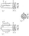
FIG. 1A is side view of a luer lock adapter; -
FIG. 1B is a side view of the luer lock adapter ofFIG. 1A rotated 90°; -
FIG. 1C is a top view of the luer-lock adapter ofFIG. 1A ; -
FIG. 2 is a cross-sectional view of the luer lock adapter ofFIG. 1A ; -
FIG. 3A is a side view of another embodiment of a luer lock adapter; -
FIG. 3B is a side view of another alternate embodiment of a luer lock adapter; -
FIG. 3C is a side view of another alternate embodiment of a luer lock adapter. -
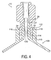
FIG. 4 is a cross-sectional view of the luer lock adapter ofFIG. 1A attached to a medical receptacle; and -
FIG. 5 is a cross-sectional view of an alternate embodiment of a luer lock adapter attached to a medical receptacle. - Referring now to
FIGS. 1A, 1B, 1C and2 , anadapter 10 for attachment to a medical device is illustrated. Theadapter 10 may include aproximal end 20 having a taperedrecess 22 formed therein. Theadapter 10 may also include adistal end 30 having acylindrical recess 32 formed therein. Theadapter 10 may also include aconduit 40 formed between thetapered recess 22 and thecylindrical recess 32. Theconduit 40 may be in fluid communication with both the taperedrecess 22 and thecylindrical recess 32. - In construction, the
adapter 10 may comprise a rigid or semi-rigid material such as metal, hard plastic or a composite. Theadapter 10 may be molded, machined or otherwise formed with the required features and dimensions. - As shown in
FIGS. 1A and 1B , theadapter 10 may be generally cylindrical in shape and may have a longitudinal axis L. The adapter may also include asurface portion 33 which includes a means for gripping 34. In one embodiment, the means for gripping 34 may comprise at least two wings which extend outwardly from thesurface portion 33. It is envisioned that the means for gripping 34 are dimensioned such that they may not permit an individual twisting theadapter 10 to achieve sufficient mechanical advantage to over-torque theadapter 10, thereby damaging the adapter and/or the medical device to which theadapter 10 may be attached. The receptacle may be susceptible to damage, for example, at the intersection of the skirt with the syringe barrel as well as at the intersection of the tapered post with the syringe barrel. In an alternate embodiment as shown inFIG. 3A , the means for gripping 34' may include at least two wings which may be spaced approximately 180° apart about thesurface portion 33 and are angled axially by an angle a. The angle a may be chosen such that when a user attempts to over-torque theadapter 10, the user's fingers may slip off of the means for gripping, thereby preventing over-torqueing. For example, angle a may be 5°. In other alternate embodiments, the means for gripping may beribs 34", as shown inFIG. 3B , or knurls 341"', as shown inFIG. 3C . - As shown in
FIG 2 , theadapter 10 may include atapered recess 22 defined by an,interior wall 26, achamfer 27, and aseat 28. In one embodiment, theseat 28 may be perpendicular to the longitudinal axis L. It is also envisioned that the angle between theseat 28 and thewall 26, angle ß, may be approximately 90°. Furthermore, it is envisioned that the angle ß may be less than 90° in instances where theseat 28 is angled toward and into the taperedrecess 22, rather than being oriented approximately perpendicular to the longitudinal axis L. It is also envisioned that the angle between theseat 28 and thechamfer 27, angle y, may be between approximately 90° and less than 180°. - Referring now to
FIG. 4 , the distal end of theadapter 30 may also include acylindrical recess 32, into which a medical instrument, including medical tubing or needles, may be affixed by a suitable method such as such as welding, brazing or press fitting. Alternately, theadapter 10 and the medical instrument may be machined or molded from a same piece of material. - Referring again to
FIG. 1A , Theadapter 10 may also include aproximal end 20 having a threadedsurface 23. The threadedsurface 23 may include at least onethread 24 extending therefrom. The at least onethread 24 may facilitate threading engagement with a medical receptacle which may have a skirt with an outside diameter and a threaded inside diameter. In one embodiment, the at least onethread 24 may be a plurality of threads. In another embodiment, the at least onethread 24 may be two threads. Specifically, the thread configuration may be of the double-start, double-thread variety. - With reference again to
FIG. 4 , theadapter 10 may be threadingly attached tomedical receptacle 100 having askirt 110 with anoutside diameter 112 and aninside diameter 114 which may includethreads 116. The at least onethread 24 may be configured such that the at least onetread 24 may threadingly engage thethreads 116 of the inside diameter of theskirt 110. Providing the at least onethread 24 as two threads may result in increased contact between the at least onethread 24 and thethreads 116 of themedical receptacle 116. As indicated by the configuration of the at least onethread 24 inFIG. 4 , the at least onethread 24 contacts theskirt threads 116 at two points spaced approximately 180° apart on the diameter of theadapter 10. Thus, if a force perpendicular to the longitudinal axis is applied to theadapter 10 from one direction, the at least onethread 24 on the side of theadapter 10 from which the force is applied may tend to deflect upward and contact the top surface of thecorresponding thread 116. In contrast, the at least onethread 24 on the opposite side of theadapter 10 from which the force is applied may tend to deflect downward and contact the bottom surface of thecorresponding thread 116, thereby creating two points of contact between theadapter 10 and thereceptacle 100 and providing additional resistance to the applied force. In contrast, prior art adapters may include only one thread and thus have only one point of contact with the receptacle. As there is no second point of contact between the receptacle and the adapters of the prior art, the force applied to a prior art adapter may likely crack the threads attached to the adapter or in extreme cases, shear the threads from the adapter completely. Thus, it is envisioned that the at least onethread 24 is designed to achieve sufficient mechanical advantage such that this type of damage to theadapter 10, as well damage at the intersection of theskirt 110 with the syringe barrel and at the intersection of the taperedpost 120 with the syringe barrel, is thereby reduced when theadapter 10 is subjected to forces perpendicular to its longitudinal axis. - With continued reference to
FIG. 4 , theadapter 10 may be attached to thereceptacle 100 by aligning the taperedpost 120 of thereceptacle 110 with the taperedrecess 22 and pressing theadapter 10 onto the taperedpost 120 while simultaneously engaging the at least onethread 24 with thethreads 116 of theskirt 110. While twisting theadapter 10, the end of the taperedpost 120 may contact theseat 28, at which point the user may feel resistance, which may indicate that theadapter 10 has been fully engaged with thereceptacle 100. By contrast, prior art tapered recesses have not included seats such as those presently disclosed, whereby over-torqueing and resultant damage to tapered posts are therefore common occurrences. - In an alternate embodiment shown in
FIG. 5 , the adapter 10' may include acollar 50 which extends from thesurface portion 32. Thus, as the adapter 10' is attached to thereceptacle 100, thecollar 50 may contact atop surface 118 of theskirt 100, such that thecollar 50 acts as a mechanical stop which may prevent a user from over-torqueing the adapter 10', thus preventing damage to the adapter 10' and themedical receptacle 100. Furthermore, thecollar 50 may also act as a visual cue to the user attaching the adapter 10' to thereceptacle 100, in that a gap between thecollar 50 and thetop surface 118 may be present until the adapter 10' has been sufficiently tightened. Thus, a user may be signaled that the adapter 10' has been sufficiently tightened once any gap has disappeared. - The invention has been described herein with reference to the disclosed embodiments. Obviously, modifications and alterations will occur to others upon a reading and understanding of this specification. It is intended to include all such modifications and alterations insofar as they come within the scope of the appended claims or the equivalence thereof.
Claims (15)
- A luer adapter (10) for a medical receptacle (100), said receptacle (100) having a skirt (110) with an outside diameter (112) and a threaded inside diameter (114), and a tapered post (120) within the skirt (110), the adapter (10) comprising:- a proximal end (20) portion having a threaded surface (23) including at least one thread (2) configured to threadingly engage the threaded inside diameter of the skirt (110);- a distal end (30) portion having a surface portion (33) which includes a means for gripping and a cylindrical recess (32);- a conduit (40) positioned between the tapered recess (22) and the cylindrical recess (32) such that the conduit (40) is in fluid communication with both the tapered recess (22) and the cylindrical recess (32); and- a longitudinal axis;
characterized in that
the proximal end (20) portion including a tapered recess (22) defined by a wall (26), a chamfer (27), and a seat (28), the chamfer (27) having a flat transition from the wall (26) to the seat (28). - The adapter (10) of claim 1, wherein the seat (28) is perpendicular to the longitudinal axis.
- The adapter (10) of claim 1, wherein the angle formed between the seat (28) and the wall (26) is approximately 90°.
- The adapter (10) of claim 1, wherein the angle formed between the seat (28) and the wall (26) is less than 90°.
- The adapter (10) of claim 1, wherein the angle formed between the seat (28) and the chamfer (27) is greater than approximately 90° and less than approximately 180°.
- The adapter (10) of claim 1, wherein the at least one thread (24) is a plurality of threads.
- The adapter (10) of claim 1, wherein the means for gripping is at least two wings extending from the surface portion (33).
- The adapter (10) of claim 1, wherein the means for gripping is selected from the group consisting of a plurality of ribs and a plurality of knurls.
- The adapter (10) of claim 1, wherein the surface portion (33) further includes a collar (50) projecting therefrom.
- A method for securing a luer adapter (10) to a medical receptacle (100), said receptacle (100) having a skirt (110) with an outside diameter (112) and a threaded inside diameter (114), and a tapered post (120) within a hub, the method characterized by the steps of:(a) providing a luer adapter (10) comprising a proximal end (20) portion having a threaded surface (23) including at least one thread (24) configured to threadingly engage the threaded inside diameter of the skirt (110), the proximal end (20) portion including a tapered recess (22) defined by a wall (26), a chamfer (27), and a seat (28), the chamfer (27) having a flat transition from the wall (26) to the seat (28), a distal end (30) portion having a surface portion (33) and cylindrical recess (32); a conduit (40) positioned between the tapered recess (22) and the cylindrical recess (32) such that the conduit (40) is in fluid communication with both the tapered recess (22) and the cylindrical recess (32);
and a longitudinal axis;
wherein the surface portion (33) includes a means for gripping;(b) inserting the tapered post (120) into the tapered recess (22); and(c) twisting the adapter (10) to engage the at least one thread (24) of the adapter (10) with the threaded inside diameter of the skirt (110) of the medical receptacle (100). - The method of claim 10, wherein the seat (28) is perpendicular to the longitudinal axis.
- The method of claim 10, wherein the means for gripping is at least two wings extending from the surface portion (33).
- The method of claim 10, wherein the at least on thread (24) is a plurality of threads.
- The method of claim 10, wherein the surface portion (33) further includes a collar (50) projecting therefrom.
- The method of claim 10,
wherein the proximal end (20) further includes a collar (50) projecting from the threaded surface (23), and wherein the method further comprises the following step:- twisting the adapter (10) to engage the at least one thread (24) of the adapter (10) with the threaded inside diameter of the skirt (110) until the collar (50) contacts the upper surface (118) of the skirt (110).
Applications Claiming Priority (1)
| Application Number | Priority Date | Filing Date | Title |
|---|---|---|---|
| US12/249,199 US8372057B2 (en) | 2008-10-10 | 2008-10-10 | Luer lock adapter |
Publications (3)
| Publication Number | Publication Date |
|---|---|
| EP2174687A2 EP2174687A2 (en) | 2010-04-14 |
| EP2174687A3 EP2174687A3 (en) | 2011-02-09 |
| EP2174687B1 true EP2174687B1 (en) | 2016-03-16 |
Family
ID=41634719
Family Applications (1)
| Application Number | Title | Priority Date | Filing Date |
|---|---|---|---|
| EP09012835.6A Active EP2174687B1 (en) | 2008-10-10 | 2009-10-09 | Luer lock adapter |
Country Status (4)
| Country | Link |
|---|---|
| US (2) | US8372057B2 (en) |
| EP (1) | EP2174687B1 (en) |
| CN (1) | CN101756785B (en) |
| ES (1) | ES2572814T3 (en) |
Families Citing this family (154)
| Publication number | Priority date | Publication date | Assignee | Title |
|---|---|---|---|---|
| US10285694B2 (en) | 2001-10-20 | 2019-05-14 | Covidien Lp | Surgical stapler with timer and feedback display |
| US10041822B2 (en) | 2007-10-05 | 2018-08-07 | Covidien Lp | Methods to shorten calibration times for powered devices |
| US11311291B2 (en) | 2003-10-17 | 2022-04-26 | Covidien Lp | Surgical adapter assemblies for use between surgical handle assembly and surgical end effectors |
| US10022123B2 (en) | 2012-07-09 | 2018-07-17 | Covidien Lp | Surgical adapter assemblies for use between surgical handle assembly and surgical end effectors |
| WO2006015319A2 (en) | 2004-07-30 | 2006-02-09 | Power Medical Interventions, Inc. | Flexible shaft extender and method of using same |
| US11291443B2 (en) | 2005-06-03 | 2022-04-05 | Covidien Lp | Surgical stapler with timer and feedback display |
| US7918230B2 (en) | 2007-09-21 | 2011-04-05 | Tyco Healthcare Group Lp | Surgical device having a rotatable jaw portion |
| US10498269B2 (en) | 2007-10-05 | 2019-12-03 | Covidien Lp | Powered surgical stapling device |
| US8517241B2 (en) | 2010-04-16 | 2013-08-27 | Covidien Lp | Hand-held surgical devices |
| US10779818B2 (en) | 2007-10-05 | 2020-09-22 | Covidien Lp | Powered surgical stapling device |
| GB0906640D0 (en) * | 2009-04-17 | 2009-06-03 | Owen Mumford Ltd | A needle cap assembly |
| US9364651B2 (en) | 2010-02-23 | 2016-06-14 | Smiths Medical Asd, Inc. | Adapter with special fitting |
| US8292150B2 (en) | 2010-11-02 | 2012-10-23 | Tyco Healthcare Group Lp | Adapter for powered surgical devices |
| US9700709B2 (en) * | 2011-01-31 | 2017-07-11 | Shl Group Ab | Coupling arrangement |
| US8870238B2 (en) * | 2011-06-27 | 2014-10-28 | Smiths Medical Asd, Inc. | Fitting for medicament infusion systems |
| US9220833B2 (en) | 2011-06-27 | 2015-12-29 | Smiths Medical Asd, Inc. | Medicament infusion systems |
| US8986226B2 (en) | 2011-10-05 | 2015-03-24 | Coeur, Inc. | Guidewire positioning tool |
| US8899462B2 (en) | 2011-10-25 | 2014-12-02 | Covidien Lp | Apparatus for endoscopic procedures |
| US8672206B2 (en) | 2011-10-25 | 2014-03-18 | Covidien Lp | Apparatus for endoscopic procedures |
| US9492146B2 (en) | 2011-10-25 | 2016-11-15 | Covidien Lp | Apparatus for endoscopic procedures |
| US8657177B2 (en) | 2011-10-25 | 2014-02-25 | Covidien Lp | Surgical apparatus and method for endoscopic surgery |
| US9480492B2 (en) | 2011-10-25 | 2016-11-01 | Covidien Lp | Apparatus for endoscopic procedures |
| US11207089B2 (en) | 2011-10-25 | 2021-12-28 | Covidien Lp | Apparatus for endoscopic procedures |
| US9364231B2 (en) | 2011-10-27 | 2016-06-14 | Covidien Lp | System and method of using simulation reload to optimize staple formation |
| US10737087B2 (en) | 2012-04-17 | 2020-08-11 | Smiths Medical Asd, Inc. | Filling fitting |
| US9868198B2 (en) | 2012-06-01 | 2018-01-16 | Covidien Lp | Hand held surgical handle assembly, surgical adapters for use between surgical handle assembly and surgical loading units, and methods of use |
| US10080563B2 (en) | 2012-06-01 | 2018-09-25 | Covidien Lp | Loading unit detection assembly and surgical device for use therewith |
| US9597104B2 (en) | 2012-06-01 | 2017-03-21 | Covidien Lp | Handheld surgical handle assembly, surgical adapters for use between surgical handle assembly and surgical end effectors, and methods of use |
| US9364220B2 (en) | 2012-06-19 | 2016-06-14 | Covidien Lp | Apparatus for endoscopic procedures |
| US10492814B2 (en) | 2012-07-09 | 2019-12-03 | Covidien Lp | Apparatus for endoscopic procedures |
| US9839480B2 (en) | 2012-07-09 | 2017-12-12 | Covidien Lp | Surgical adapter assemblies for use between surgical handle assembly and surgical end effectors |
| US9955965B2 (en) | 2012-07-09 | 2018-05-01 | Covidien Lp | Switch block control assembly of a medical device |
| US9402604B2 (en) | 2012-07-20 | 2016-08-02 | Covidien Lp | Apparatus for endoscopic procedures |
| US9421014B2 (en) | 2012-10-18 | 2016-08-23 | Covidien Lp | Loading unit velocity and position feedback |
| US9782187B2 (en) | 2013-01-18 | 2017-10-10 | Covidien Lp | Adapter load button lockout |
| US10918364B2 (en) | 2013-01-24 | 2021-02-16 | Covidien Lp | Intelligent adapter assembly for use with an electromechanical surgical system |
| US9216013B2 (en) | 2013-02-18 | 2015-12-22 | Covidien Lp | Apparatus for endoscopic procedures |
| US9421003B2 (en) | 2013-02-18 | 2016-08-23 | Covidien Lp | Apparatus for endoscopic procedures |
| US9492189B2 (en) | 2013-03-13 | 2016-11-15 | Covidien Lp | Apparatus for endoscopic procedures |
| US9775610B2 (en) | 2013-04-09 | 2017-10-03 | Covidien Lp | Apparatus for endoscopic procedures |
| US9700318B2 (en) | 2013-04-09 | 2017-07-11 | Covidien Lp | Apparatus for endoscopic procedures |
| US9968771B2 (en) | 2013-05-16 | 2018-05-15 | Becton Dickinson and Company Limited | Mechanical friction enhancement for threaded connection incorporating crushable ribs |
| US10098816B2 (en) * | 2013-05-16 | 2018-10-16 | Becton Dickinson and Company Ltd. | Mechanical friction enhancement for threaded connection incorporating micro-threads |
| US9895290B2 (en) * | 2013-05-16 | 2018-02-20 | Becton Dickinson and Company Ltd. | Mechanical friction enhancement for threaded connection incorporating opposing barb |
| US9801646B2 (en) | 2013-05-30 | 2017-10-31 | Covidien Lp | Adapter load button decoupled from loading unit sensor |
| US9797486B2 (en) | 2013-06-20 | 2017-10-24 | Covidien Lp | Adapter direct drive with manual retraction, lockout and connection mechanisms |
| US9757129B2 (en) | 2013-07-08 | 2017-09-12 | Covidien Lp | Coupling member configured for use with surgical devices |
| US9955966B2 (en) | 2013-09-17 | 2018-05-01 | Covidien Lp | Adapter direct drive with manual retraction, lockout, and connection mechanisms for improper use prevention |
| US9962157B2 (en) | 2013-09-18 | 2018-05-08 | Covidien Lp | Apparatus and method for differentiating between tissue and mechanical obstruction in a surgical instrument |
| US9974540B2 (en) | 2013-10-18 | 2018-05-22 | Covidien Lp | Adapter direct drive twist-lock retention mechanism |
| US9295522B2 (en) | 2013-11-08 | 2016-03-29 | Covidien Lp | Medical device adapter with wrist mechanism |
| US10236616B2 (en) | 2013-12-04 | 2019-03-19 | Covidien Lp | Adapter assembly for interconnecting surgical devices and surgical attachments, and surgical systems thereof |
| ES2755485T3 (en) | 2013-12-09 | 2020-04-22 | Covidien Lp | Adapter assembly for the interconnection of electromechanical surgical devices and surgical load units, and surgical systems thereof |
| US9918713B2 (en) | 2013-12-09 | 2018-03-20 | Covidien Lp | Adapter assembly for interconnecting electromechanical surgical devices and surgical loading units, and surgical systems thereof |
| CN105813582B (en) | 2013-12-11 | 2019-05-28 | 柯惠Lp公司 | Wrist units and clamp assemblies for robotic surgical system |
| CN105813580B (en) | 2013-12-12 | 2019-10-15 | 柯惠Lp公司 | Gear train for robotic surgical system |
| US9808245B2 (en) | 2013-12-13 | 2017-11-07 | Covidien Lp | Coupling assembly for interconnecting an adapter assembly and a surgical device, and surgical systems thereof |
| US9839424B2 (en) | 2014-01-17 | 2017-12-12 | Covidien Lp | Electromechanical surgical assembly |
| US9655616B2 (en) | 2014-01-22 | 2017-05-23 | Covidien Lp | Apparatus for endoscopic procedures |
| US10226305B2 (en) | 2014-02-12 | 2019-03-12 | Covidien Lp | Surgical end effectors and pulley assemblies thereof |
| US9301691B2 (en) | 2014-02-21 | 2016-04-05 | Covidien Lp | Instrument for optically detecting tissue attributes |
| CN106132322B (en) | 2014-03-31 | 2019-11-08 | 柯惠Lp公司 | The wrist units and clamp assemblies of robotic surgical system |
| US10164466B2 (en) | 2014-04-17 | 2018-12-25 | Covidien Lp | Non-contact surgical adapter electrical interface |
| US10080552B2 (en) | 2014-04-21 | 2018-09-25 | Covidien Lp | Adapter assembly with gimbal for interconnecting electromechanical surgical devices and surgical loading units, and surgical systems thereof |
| CN106413663B (en) * | 2014-04-21 | 2019-02-12 | 贝克顿迪金森有限公司 | The syringe adapter being disengaged with compound motion |
| US9861366B2 (en) | 2014-05-06 | 2018-01-09 | Covidien Lp | Ejecting assembly for a surgical stapler |
| US9713466B2 (en) | 2014-05-16 | 2017-07-25 | Covidien Lp | Adaptor for surgical instrument for converting rotary input to linear output |
| US9763661B2 (en) | 2014-06-26 | 2017-09-19 | Covidien Lp | Adapter assembly for interconnecting electromechanical surgical devices and surgical loading units, and surgical systems thereof |
| US10561418B2 (en) | 2014-06-26 | 2020-02-18 | Covidien Lp | Adapter assemblies for interconnecting surgical loading units and handle assemblies |
| US9839425B2 (en) | 2014-06-26 | 2017-12-12 | Covidien Lp | Adapter assembly for interconnecting electromechanical surgical devices and surgical loading units, and surgical systems thereof |
| US9987095B2 (en) | 2014-06-26 | 2018-06-05 | Covidien Lp | Adapter assemblies for interconnecting electromechanical handle assemblies and surgical loading units |
| US10163589B2 (en) | 2014-06-26 | 2018-12-25 | Covidien Lp | Adapter assemblies for interconnecting surgical loading units and handle assemblies |
| WO2016057225A1 (en) | 2014-10-07 | 2016-04-14 | Covidien Lp | Handheld electromechanical surgical system |
| US10226254B2 (en) | 2014-10-21 | 2019-03-12 | Covidien Lp | Adapter, extension, and connector assemblies for surgical devices |
| US10729443B2 (en) | 2014-10-21 | 2020-08-04 | Covidien Lp | Adapter, extension, and connector assemblies for surgical devices |
| US9949737B2 (en) | 2014-10-22 | 2018-04-24 | Covidien Lp | Adapter assemblies for interconnecting surgical loading units and handle assemblies |
| US10085750B2 (en) | 2014-10-22 | 2018-10-02 | Covidien Lp | Adapter with fire rod J-hook lockout |
| US20180014998A1 (en) * | 2015-01-19 | 2018-01-18 | Jms Co., Ltd. | Medical liquid collection injector |
| US20170348196A1 (en) * | 2015-01-19 | 2017-12-07 | Jms Co., Ltd. | Medical liquid collection tip, liquid collection nozzle, and injector set |
| US10111665B2 (en) | 2015-02-19 | 2018-10-30 | Covidien Lp | Electromechanical surgical systems |
| US10190888B2 (en) | 2015-03-11 | 2019-01-29 | Covidien Lp | Surgical stapling instruments with linear position assembly |
| US10226239B2 (en) | 2015-04-10 | 2019-03-12 | Covidien Lp | Adapter assembly with gimbal for interconnecting electromechanical surgical devices and surgical loading units, and surgical systems thereof |
| US11432902B2 (en) | 2015-04-10 | 2022-09-06 | Covidien Lp | Surgical devices with moisture control |
| US10327779B2 (en) | 2015-04-10 | 2019-06-25 | Covidien Lp | Adapter, extension, and connector assemblies for surgical devices |
| WO2016171947A1 (en) | 2015-04-22 | 2016-10-27 | Covidien Lp | Handheld electromechanical surgical system |
| US11278286B2 (en) | 2015-04-22 | 2022-03-22 | Covidien Lp | Handheld electromechanical surgical system |
| US10751058B2 (en) | 2015-07-28 | 2020-08-25 | Covidien Lp | Adapter assemblies for surgical devices |
| US10806454B2 (en) | 2015-09-25 | 2020-10-20 | Covidien Lp | Robotic surgical assemblies and instrument drive connectors thereof |
| US10371238B2 (en) | 2015-10-09 | 2019-08-06 | Covidien Lp | Adapter assembly for surgical device |
| US10413298B2 (en) | 2015-10-14 | 2019-09-17 | Covidien Lp | Adapter assembly for surgical devices |
| US10292705B2 (en) | 2015-11-06 | 2019-05-21 | Covidien Lp | Surgical apparatus |
| US10729435B2 (en) | 2015-11-06 | 2020-08-04 | Covidien Lp | Adapter assemblies for interconnecting surgical loading units and handle assemblies |
| US10939952B2 (en) | 2015-11-06 | 2021-03-09 | Covidien Lp | Adapter, extension, and connector assemblies for surgical devices |
| US10617411B2 (en) | 2015-12-01 | 2020-04-14 | Covidien Lp | Adapter assembly for surgical device |
| US10433841B2 (en) | 2015-12-10 | 2019-10-08 | Covidien Lp | Adapter assembly for surgical device |
| US10420554B2 (en) | 2015-12-22 | 2019-09-24 | Covidien Lp | Personalization of powered surgical devices |
| US10253847B2 (en) | 2015-12-22 | 2019-04-09 | Covidien Lp | Electromechanical surgical devices with single motor drives and adapter assemblies therfor |
| US10314579B2 (en) | 2016-01-07 | 2019-06-11 | Covidien Lp | Adapter assemblies for interconnecting surgical loading units and handle assemblies |
| US10524797B2 (en) | 2016-01-13 | 2020-01-07 | Covidien Lp | Adapter assembly including a removable trocar assembly |
| US10660623B2 (en) | 2016-01-15 | 2020-05-26 | Covidien Lp | Centering mechanism for articulation joint |
| WO2017123907A2 (en) | 2016-01-15 | 2017-07-20 | Neomed, Inc. | Large bore enteral connector |
| US10508720B2 (en) | 2016-01-21 | 2019-12-17 | Covidien Lp | Adapter assembly with planetary gear drive for interconnecting electromechanical surgical devices and surgical loading units, and surgical systems thereof |
| US10398439B2 (en) | 2016-02-10 | 2019-09-03 | Covidien Lp | Adapter, extension, and connector assemblies for surgical devices |
| WO2017192287A1 (en) * | 2016-05-02 | 2017-11-09 | Amgen Inc. | Syringe adapter and guide for filling an on-body injector |
| US10799239B2 (en) | 2016-05-09 | 2020-10-13 | Covidien Lp | Adapter assembly with pulley system and worm gear drive for interconnecting electromechanical surgical devices and surgical end effectors |
| US10588610B2 (en) | 2016-05-10 | 2020-03-17 | Covidien Lp | Adapter assemblies for surgical devices |
| US10736637B2 (en) | 2016-05-10 | 2020-08-11 | Covidien Lp | Brake for adapter assemblies for surgical devices |
| US10702302B2 (en) | 2016-05-17 | 2020-07-07 | Covidien Lp | Adapter assembly including a removable trocar assembly |
| US10463374B2 (en) | 2016-05-17 | 2019-11-05 | Covidien Lp | Adapter assembly for a flexible circular stapler |
| AU2017269262B2 (en) | 2016-05-26 | 2021-09-09 | Covidien Lp | Robotic surgical assemblies |
| EP3266496B1 (en) * | 2016-07-08 | 2021-04-14 | Fenwal, Inc. | Adapter for medical connectors |
| US10653398B2 (en) | 2016-08-05 | 2020-05-19 | Covidien Lp | Adapter assemblies for surgical devices |
| US11116594B2 (en) | 2016-11-08 | 2021-09-14 | Covidien Lp | Surgical systems including adapter assemblies for interconnecting electromechanical surgical devices and end effectors |
| US10631945B2 (en) | 2017-02-28 | 2020-04-28 | Covidien Lp | Autoclavable load sensing device |
| US10299790B2 (en) | 2017-03-03 | 2019-05-28 | Covidien Lp | Adapter with centering mechanism for articulation joint |
| US11272929B2 (en) | 2017-03-03 | 2022-03-15 | Covidien Lp | Dynamically matching input and output shaft speeds of articulating adapter assemblies for surgical instruments |
| US10660641B2 (en) | 2017-03-16 | 2020-05-26 | Covidien Lp | Adapter with centering mechanism for articulation joint |
| US10390858B2 (en) | 2017-05-02 | 2019-08-27 | Covidien Lp | Powered surgical device with speed and current derivative motor shut off |
| US10603035B2 (en) | 2017-05-02 | 2020-03-31 | Covidien Lp | Surgical loading unit including an articulating end effector |
| US11324502B2 (en) | 2017-05-02 | 2022-05-10 | Covidien Lp | Surgical loading unit including an articulating end effector |
| US11311295B2 (en) | 2017-05-15 | 2022-04-26 | Covidien Lp | Adaptive powered stapling algorithm with calibration factor |
| US10772700B2 (en) | 2017-08-23 | 2020-09-15 | Covidien Lp | Contactless loading unit detection |
| US11583358B2 (en) | 2017-09-06 | 2023-02-21 | Covidien Lp | Boundary scaling of surgical robots |
| WO2019136041A1 (en) | 2018-01-04 | 2019-07-11 | Covidien Lp | Robotic surgical instrument including high articulation wrist assembly with torque transmission and mechanical manipulation |
| US11160556B2 (en) | 2018-04-23 | 2021-11-02 | Covidien Lp | Threaded trocar for adapter assemblies |
| US11534172B2 (en) | 2018-05-07 | 2022-12-27 | Covidien Lp | Electromechanical surgical stapler including trocar assembly release mechanism |
| US11399839B2 (en) | 2018-05-07 | 2022-08-02 | Covidien Lp | Surgical devices including trocar lock and trocar connection indicator |
| US11896230B2 (en) | 2018-05-07 | 2024-02-13 | Covidien Lp | Handheld electromechanical surgical device including load sensor having spherical ball pivots |
| US20190388091A1 (en) | 2018-06-21 | 2019-12-26 | Covidien Lp | Powered surgical devices including strain gauges incorporated into flex circuits |
| US11241233B2 (en) | 2018-07-10 | 2022-02-08 | Covidien Lp | Apparatus for ensuring strain gauge accuracy in medical reusable device |
| EP3593840A1 (en) * | 2018-07-12 | 2020-01-15 | Becton Dickinson France | Glass made luer tip with marking means and method for manufacturing the same |
| US11596496B2 (en) | 2018-08-13 | 2023-03-07 | Covidien Lp | Surgical devices with moisture control |
| EP3836847A4 (en) * | 2018-08-14 | 2022-09-21 | Covidien LP | Surgical devices including features to facilitate cleaning |
| US11076858B2 (en) | 2018-08-14 | 2021-08-03 | Covidien Lp | Single use electronics for surgical devices |
| US11510669B2 (en) | 2020-09-29 | 2022-11-29 | Covidien Lp | Hand-held surgical instruments |
| US11717276B2 (en) | 2018-10-30 | 2023-08-08 | Covidien Lp | Surgical devices including adapters and seals |
| US11241228B2 (en) | 2019-04-05 | 2022-02-08 | Covidien Lp | Surgical instrument including an adapter assembly and an articulating surgical loading unit |
| US11369378B2 (en) | 2019-04-18 | 2022-06-28 | Covidien Lp | Surgical instrument including an adapter assembly and an articulating surgical loading unit |
| US11446035B2 (en) | 2019-06-24 | 2022-09-20 | Covidien Lp | Retaining mechanisms for trocar assemblies |
| US11058429B2 (en) | 2019-06-24 | 2021-07-13 | Covidien Lp | Load sensing assemblies and methods of manufacturing load sensing assemblies |
| US11464541B2 (en) | 2019-06-24 | 2022-10-11 | Covidien Lp | Retaining mechanisms for trocar assembly |
| US11123101B2 (en) | 2019-07-05 | 2021-09-21 | Covidien Lp | Retaining mechanisms for trocar assemblies |
| US11426168B2 (en) | 2019-07-05 | 2022-08-30 | Covidien Lp | Trocar coupling assemblies for a surgical stapler |
| US11076850B2 (en) | 2019-11-26 | 2021-08-03 | Covidien Lp | Surgical instrument including an adapter assembly and an articulating surgical loading unit |
| US11737747B2 (en) | 2019-12-17 | 2023-08-29 | Covidien Lp | Hand-held surgical instruments |
| US11291446B2 (en) | 2019-12-18 | 2022-04-05 | Covidien Lp | Surgical instrument including an adapter assembly and an articulating surgical loading unit |
| US11583275B2 (en) | 2019-12-27 | 2023-02-21 | Covidien Lp | Surgical instruments including sensor assembly |
| US11504117B2 (en) | 2020-04-02 | 2022-11-22 | Covidien Lp | Hand-held surgical instruments |
| US11660091B2 (en) | 2020-09-08 | 2023-05-30 | Covidien Lp | Surgical device with seal assembly |
| US11571192B2 (en) | 2020-09-25 | 2023-02-07 | Covidien Lp | Adapter assembly for surgical devices |
| US11786248B2 (en) | 2021-07-09 | 2023-10-17 | Covidien Lp | Surgical stapling device including a buttress retention assembly |
| US11819209B2 (en) | 2021-08-03 | 2023-11-21 | Covidien Lp | Hand-held surgical instruments |
| US11862884B2 (en) | 2021-08-16 | 2024-01-02 | Covidien Lp | Surgical instrument with electrical connection |
| WO2024026363A2 (en) * | 2022-07-29 | 2024-02-01 | Maduro Discovery, Llc | Improved catheter hub |
Citations (1)
| Publication number | Priority date | Publication date | Assignee | Title |
|---|---|---|---|---|
| EP1872824A1 (en) * | 2006-06-28 | 2008-01-02 | Covidien AG | Connecting structures for luer fitting |
Family Cites Families (18)
| Publication number | Priority date | Publication date | Assignee | Title |
|---|---|---|---|---|
| GB632317A (en) | 1947-03-24 | 1949-11-21 | Samuel James Everett | Improvements relating to hypodermic syringes |
| US2564804A (en) * | 1947-03-24 | 1951-08-21 | Everett Samuel James | Needle mount for hypodermic syringes |
| US4294250A (en) * | 1979-12-07 | 1981-10-13 | Baxter Travenol Laboratories, Inc. | Luer lock connection device |
| DE3242238C2 (en) | 1982-11-15 | 1985-02-14 | Peter Dr. März | Catheter coupling |
| US5312377A (en) * | 1993-03-29 | 1994-05-17 | Dalton Michael J | Tapered luer connector |
| US5591143A (en) * | 1993-04-02 | 1997-01-07 | Medrad Inc. | Luer connector with torque indicator |
| US5651776A (en) * | 1995-03-22 | 1997-07-29 | Angiodynamics, Inc. | Luer-type connector |
| US5620427A (en) * | 1995-04-27 | 1997-04-15 | David R. Kipp | Luer lock system |
| US5782505A (en) * | 1996-08-29 | 1998-07-21 | Becton, Dickinson And Company | Catheter adapter assembly |
| US20020173748A1 (en) * | 1998-10-29 | 2002-11-21 | Mcconnell Susan | Reservoir connector |
| US6332633B1 (en) * | 1999-12-15 | 2001-12-25 | Elcam Plastic Kibbutz Bar-Am | Luer-type connector |
| DE20017013U1 (en) | 2000-09-28 | 2000-12-21 | Transcoject Gmbh | Lock for a Luer lock connection |
| US6802836B2 (en) * | 2002-02-19 | 2004-10-12 | Scimed Life Systems, Inc. | Low profile adaptor for use with a medical catheter |
| US20040155457A1 (en) * | 2003-02-12 | 2004-08-12 | Maersk Medical A/S | Connecting element comprising a first body and a method for injection moulding a connecting element |
| ATE346646T1 (en) * | 2003-02-12 | 2006-12-15 | Unomedical As | MEDICAL CONNECTOR AND METHOD FOR INJECTION MOLDING SUCH A CONNECTOR |
| JP4273971B2 (en) * | 2004-01-07 | 2009-06-03 | ニプロ株式会社 | Female connector |
| US8852167B2 (en) | 2005-12-01 | 2014-10-07 | Bayer Medical Care Inc. | Medical connector |
| US20090243281A1 (en) * | 2008-03-28 | 2009-10-01 | Icu Medical Inc. | Connectors having features to facilitate or hamper tightening and/or loosening |
-
2008
- 2008-10-10 US US12/249,199 patent/US8372057B2/en active Active
-
2009
- 2009-10-09 EP EP09012835.6A patent/EP2174687B1/en active Active
- 2009-10-09 ES ES09012835.6T patent/ES2572814T3/en active Active
- 2009-10-10 CN CN2009102097994A patent/CN101756785B/en active Active
-
2013
- 2013-02-11 US US13/764,343 patent/US9579497B2/en active Active
Patent Citations (1)
| Publication number | Priority date | Publication date | Assignee | Title |
|---|---|---|---|---|
| EP1872824A1 (en) * | 2006-06-28 | 2008-01-02 | Covidien AG | Connecting structures for luer fitting |
Also Published As
| Publication number | Publication date |
|---|---|
| US20100094260A1 (en) | 2010-04-15 |
| EP2174687A2 (en) | 2010-04-14 |
| US20130158520A1 (en) | 2013-06-20 |
| EP2174687A3 (en) | 2011-02-09 |
| CN101756785B (en) | 2013-11-06 |
| US8372057B2 (en) | 2013-02-12 |
| US9579497B2 (en) | 2017-02-28 |
| ES2572814T3 (en) | 2016-06-02 |
| CN101756785A (en) | 2010-06-30 |
Similar Documents
| Publication | Publication Date | Title |
|---|---|---|
| EP2174687B1 (en) | Luer lock adapter | |
| US6569118B2 (en) | Adapter and method of attachment for “LUER LOK” receptacles | |
| US8652094B2 (en) | Syringe with universal end-piece | |
| US7128348B2 (en) | Female connector | |
| CA3030073C (en) | Infusion reservoir with push-on connector features and/or attachments therefor | |
| US20110178496A1 (en) | Method of preventing inadvertent interconnection in medical systems using adapter | |
| US9017291B2 (en) | Luer connector | |
| US20020147429A1 (en) | Syringes, connectors, and syringe and connector systems for use in fluid delivery systems | |
| EP1051988A2 (en) | Threaded latching mechanism | |
| JP2009006164A (en) | Needleless connector | |
| MX2007004474A (en) | Safety medical syringe with retractable needle. | |
| JP7138655B2 (en) | Adapter for connecting connector to drug delivery device | |
| JP2020523044A (en) | Syringe with luer lock connection | |
| CN113939331B (en) | Luer with a microporous tube retention pocket integrated with an axial spline | |
| EP2872202B1 (en) | Low residual volume syringe/conduit combination and syringe for such a syringe/conduit combination | |
| US20130079754A1 (en) | Connection system | |
| CN108014415B (en) | Large-pitch anti-torsion guide pipe joint | |
| KR20230110767A (en) | CATHETER ADAPTER SYSTEM FOR PROXIMALLY TRIMMABLE CATHETER |
Legal Events
| Date | Code | Title | Description |
|---|---|---|---|
| PUAI | Public reference made under article 153(3) epc to a published international application that has entered the european phase |
Free format text: ORIGINAL CODE: 0009012 |
|
| AK | Designated contracting states |
Kind code of ref document: A2 Designated state(s): AT BE BG CH CY CZ DE DK EE ES FI FR GB GR HR HU IE IS IT LI LT LU LV MC MK MT NL NO PL PT RO SE SI SK SM TR |
|
| AX | Request for extension of the european patent |
Extension state: AL BA RS |
|
| PUAL | Search report despatched |
Free format text: ORIGINAL CODE: 0009013 |
|
| RIC1 | Information provided on ipc code assigned before grant |
Ipc: A61M 39/12 20060101ALI20101228BHEP Ipc: A61M 39/10 20060101AFI20100210BHEP |
|
| AK | Designated contracting states |
Kind code of ref document: A3 Designated state(s): AT BE BG CH CY CZ DE DK EE ES FI FR GB GR HR HU IE IS IT LI LT LU LV MC MK MT NL NO PL PT RO SE SI SK SM TR |
|
| AX | Request for extension of the european patent |
Extension state: AL BA RS |
|
| 17P | Request for examination filed |
Effective date: 20110809 |
|
| 17Q | First examination report despatched |
Effective date: 20130103 |
|
| GRAP | Despatch of communication of intention to grant a patent |
Free format text: ORIGINAL CODE: EPIDOSNIGR1 |
|
| INTG | Intention to grant announced |
Effective date: 20151113 |
|
| GRAS | Grant fee paid |
Free format text: ORIGINAL CODE: EPIDOSNIGR3 |
|
| GRAA | (expected) grant |
Free format text: ORIGINAL CODE: 0009210 |
|
| AK | Designated contracting states |
Kind code of ref document: B1 Designated state(s): AT BE BG CH CY CZ DE DK EE ES FI FR GB GR HR HU IE IS IT LI LT LU LV MC MK MT NL NO PL PT RO SE SI SK SM TR |
|
| REG | Reference to a national code |
Ref country code: GB Ref legal event code: FG4D |
|
| REG | Reference to a national code |
Ref country code: CH Ref legal event code: EP |
|
| REG | Reference to a national code |
Ref country code: IE Ref legal event code: FG4D |
|
| REG | Reference to a national code |
Ref country code: AT Ref legal event code: REF Ref document number: 780663 Country of ref document: AT Kind code of ref document: T Effective date: 20160415 |
|
| REG | Reference to a national code |
Ref country code: DE Ref legal event code: R096 Ref document number: 602009036767 Country of ref document: DE |
|
| REG | Reference to a national code |
Ref country code: ES Ref legal event code: FG2A Ref document number: 2572814 Country of ref document: ES Kind code of ref document: T3 Effective date: 20160602 |
|
| REG | Reference to a national code |
Ref country code: NL Ref legal event code: MP Effective date: 20160316 |
|
| REG | Reference to a national code |
Ref country code: LT Ref legal event code: MG4D |
|
| PG25 | Lapsed in a contracting state [announced via postgrant information from national office to epo] |
Ref country code: FI Free format text: LAPSE BECAUSE OF FAILURE TO SUBMIT A TRANSLATION OF THE DESCRIPTION OR TO PAY THE FEE WITHIN THE PRESCRIBED TIME-LIMIT Effective date: 20160316 Ref country code: GR Free format text: LAPSE BECAUSE OF FAILURE TO SUBMIT A TRANSLATION OF THE DESCRIPTION OR TO PAY THE FEE WITHIN THE PRESCRIBED TIME-LIMIT Effective date: 20160617 Ref country code: HR Free format text: LAPSE BECAUSE OF FAILURE TO SUBMIT A TRANSLATION OF THE DESCRIPTION OR TO PAY THE FEE WITHIN THE PRESCRIBED TIME-LIMIT Effective date: 20160316 Ref country code: NO Free format text: LAPSE BECAUSE OF FAILURE TO SUBMIT A TRANSLATION OF THE DESCRIPTION OR TO PAY THE FEE WITHIN THE PRESCRIBED TIME-LIMIT Effective date: 20160616 |
|
| REG | Reference to a national code |
Ref country code: AT Ref legal event code: MK05 Ref document number: 780663 Country of ref document: AT Kind code of ref document: T Effective date: 20160316 |
|
| PG25 | Lapsed in a contracting state [announced via postgrant information from national office to epo] |
Ref country code: SE Free format text: LAPSE BECAUSE OF FAILURE TO SUBMIT A TRANSLATION OF THE DESCRIPTION OR TO PAY THE FEE WITHIN THE PRESCRIBED TIME-LIMIT Effective date: 20160316 Ref country code: LV Free format text: LAPSE BECAUSE OF FAILURE TO SUBMIT A TRANSLATION OF THE DESCRIPTION OR TO PAY THE FEE WITHIN THE PRESCRIBED TIME-LIMIT Effective date: 20160316 Ref country code: NL Free format text: LAPSE BECAUSE OF FAILURE TO SUBMIT A TRANSLATION OF THE DESCRIPTION OR TO PAY THE FEE WITHIN THE PRESCRIBED TIME-LIMIT Effective date: 20160316 Ref country code: LT Free format text: LAPSE BECAUSE OF FAILURE TO SUBMIT A TRANSLATION OF THE DESCRIPTION OR TO PAY THE FEE WITHIN THE PRESCRIBED TIME-LIMIT Effective date: 20160316 |
|
| REG | Reference to a national code |
Ref country code: FR Ref legal event code: PLFP Year of fee payment: 8 |
|
| PG25 | Lapsed in a contracting state [announced via postgrant information from national office to epo] |
Ref country code: PL Free format text: LAPSE BECAUSE OF FAILURE TO SUBMIT A TRANSLATION OF THE DESCRIPTION OR TO PAY THE FEE WITHIN THE PRESCRIBED TIME-LIMIT Effective date: 20160316 Ref country code: IS Free format text: LAPSE BECAUSE OF FAILURE TO SUBMIT A TRANSLATION OF THE DESCRIPTION OR TO PAY THE FEE WITHIN THE PRESCRIBED TIME-LIMIT Effective date: 20160716 Ref country code: EE Free format text: LAPSE BECAUSE OF FAILURE TO SUBMIT A TRANSLATION OF THE DESCRIPTION OR TO PAY THE FEE WITHIN THE PRESCRIBED TIME-LIMIT Effective date: 20160316 |
|
| PG25 | Lapsed in a contracting state [announced via postgrant information from national office to epo] |
Ref country code: SM Free format text: LAPSE BECAUSE OF FAILURE TO SUBMIT A TRANSLATION OF THE DESCRIPTION OR TO PAY THE FEE WITHIN THE PRESCRIBED TIME-LIMIT Effective date: 20160316 Ref country code: SK Free format text: LAPSE BECAUSE OF FAILURE TO SUBMIT A TRANSLATION OF THE DESCRIPTION OR TO PAY THE FEE WITHIN THE PRESCRIBED TIME-LIMIT Effective date: 20160316 Ref country code: CZ Free format text: LAPSE BECAUSE OF FAILURE TO SUBMIT A TRANSLATION OF THE DESCRIPTION OR TO PAY THE FEE WITHIN THE PRESCRIBED TIME-LIMIT Effective date: 20160316 Ref country code: RO Free format text: LAPSE BECAUSE OF FAILURE TO SUBMIT A TRANSLATION OF THE DESCRIPTION OR TO PAY THE FEE WITHIN THE PRESCRIBED TIME-LIMIT Effective date: 20160316 Ref country code: PT Free format text: LAPSE BECAUSE OF FAILURE TO SUBMIT A TRANSLATION OF THE DESCRIPTION OR TO PAY THE FEE WITHIN THE PRESCRIBED TIME-LIMIT Effective date: 20160718 Ref country code: AT Free format text: LAPSE BECAUSE OF FAILURE TO SUBMIT A TRANSLATION OF THE DESCRIPTION OR TO PAY THE FEE WITHIN THE PRESCRIBED TIME-LIMIT Effective date: 20160316 |
|
| REG | Reference to a national code |
Ref country code: DE Ref legal event code: R097 Ref document number: 602009036767 Country of ref document: DE |
|
| PG25 | Lapsed in a contracting state [announced via postgrant information from national office to epo] |
Ref country code: BE Free format text: LAPSE BECAUSE OF FAILURE TO SUBMIT A TRANSLATION OF THE DESCRIPTION OR TO PAY THE FEE WITHIN THE PRESCRIBED TIME-LIMIT Effective date: 20160316 |
|
| PLBE | No opposition filed within time limit |
Free format text: ORIGINAL CODE: 0009261 |
|
| STAA | Information on the status of an ep patent application or granted ep patent |
Free format text: STATUS: NO OPPOSITION FILED WITHIN TIME LIMIT |
|
| PG25 | Lapsed in a contracting state [announced via postgrant information from national office to epo] |
Ref country code: DK Free format text: LAPSE BECAUSE OF FAILURE TO SUBMIT A TRANSLATION OF THE DESCRIPTION OR TO PAY THE FEE WITHIN THE PRESCRIBED TIME-LIMIT Effective date: 20160316 |
|
| 26N | No opposition filed |
Effective date: 20161219 |
|
| PG25 | Lapsed in a contracting state [announced via postgrant information from national office to epo] |
Ref country code: BG Free format text: LAPSE BECAUSE OF FAILURE TO SUBMIT A TRANSLATION OF THE DESCRIPTION OR TO PAY THE FEE WITHIN THE PRESCRIBED TIME-LIMIT Effective date: 20160616 |
|
| PG25 | Lapsed in a contracting state [announced via postgrant information from national office to epo] |
Ref country code: SI Free format text: LAPSE BECAUSE OF FAILURE TO SUBMIT A TRANSLATION OF THE DESCRIPTION OR TO PAY THE FEE WITHIN THE PRESCRIBED TIME-LIMIT Effective date: 20160316 |
|
| REG | Reference to a national code |
Ref country code: CH Ref legal event code: PL |
|
| REG | Reference to a national code |
Ref country code: IE Ref legal event code: MM4A |
|
| PG25 | Lapsed in a contracting state [announced via postgrant information from national office to epo] |
Ref country code: LI Free format text: LAPSE BECAUSE OF NON-PAYMENT OF DUE FEES Effective date: 20161031 Ref country code: CH Free format text: LAPSE BECAUSE OF NON-PAYMENT OF DUE FEES Effective date: 20161031 |
|
| PG25 | Lapsed in a contracting state [announced via postgrant information from national office to epo] |
Ref country code: LU Free format text: LAPSE BECAUSE OF NON-PAYMENT OF DUE FEES Effective date: 20161009 |
|
| REG | Reference to a national code |
Ref country code: FR Ref legal event code: PLFP Year of fee payment: 9 |
|
| PG25 | Lapsed in a contracting state [announced via postgrant information from national office to epo] |
Ref country code: IE Free format text: LAPSE BECAUSE OF NON-PAYMENT OF DUE FEES Effective date: 20161009 |
|
| PG25 | Lapsed in a contracting state [announced via postgrant information from national office to epo] |
Ref country code: HU Free format text: LAPSE BECAUSE OF FAILURE TO SUBMIT A TRANSLATION OF THE DESCRIPTION OR TO PAY THE FEE WITHIN THE PRESCRIBED TIME-LIMIT; INVALID AB INITIO Effective date: 20091009 Ref country code: CY Free format text: LAPSE BECAUSE OF FAILURE TO SUBMIT A TRANSLATION OF THE DESCRIPTION OR TO PAY THE FEE WITHIN THE PRESCRIBED TIME-LIMIT Effective date: 20160316 |
|
| PG25 | Lapsed in a contracting state [announced via postgrant information from national office to epo] |
Ref country code: MC Free format text: LAPSE BECAUSE OF FAILURE TO SUBMIT A TRANSLATION OF THE DESCRIPTION OR TO PAY THE FEE WITHIN THE PRESCRIBED TIME-LIMIT Effective date: 20160316 Ref country code: MT Free format text: LAPSE BECAUSE OF NON-PAYMENT OF DUE FEES Effective date: 20161031 Ref country code: MK Free format text: LAPSE BECAUSE OF FAILURE TO SUBMIT A TRANSLATION OF THE DESCRIPTION OR TO PAY THE FEE WITHIN THE PRESCRIBED TIME-LIMIT Effective date: 20160316 Ref country code: TR Free format text: LAPSE BECAUSE OF FAILURE TO SUBMIT A TRANSLATION OF THE DESCRIPTION OR TO PAY THE FEE WITHIN THE PRESCRIBED TIME-LIMIT Effective date: 20160316 |
|
| REG | Reference to a national code |
Ref country code: FR Ref legal event code: PLFP Year of fee payment: 10 |
|
| P01 | Opt-out of the competence of the unified patent court (upc) registered |
Effective date: 20231101 |
|
| PGFP | Annual fee paid to national office [announced via postgrant information from national office to epo] |
Ref country code: GB Payment date: 20231027 Year of fee payment: 15 |
|
| PGFP | Annual fee paid to national office [announced via postgrant information from national office to epo] |
Ref country code: ES Payment date: 20231102 Year of fee payment: 15 |
|
| PGFP | Annual fee paid to national office [announced via postgrant information from national office to epo] |
Ref country code: IT Payment date: 20231023 Year of fee payment: 15 Ref country code: FR Payment date: 20231025 Year of fee payment: 15 Ref country code: DE Payment date: 20231027 Year of fee payment: 15 |