EP3082707B1 - Protective cap for a dispenser, and dispenser for discharging pharmaceutical and/or cosmetic liquids - Google Patents
Protective cap for a dispenser, and dispenser for discharging pharmaceutical and/or cosmetic liquids Download PDFInfo
- Publication number
- EP3082707B1 EP3082707B1 EP14802906.9A EP14802906A EP3082707B1 EP 3082707 B1 EP3082707 B1 EP 3082707B1 EP 14802906 A EP14802906 A EP 14802906A EP 3082707 B1 EP3082707 B1 EP 3082707B1
- Authority
- EP
- European Patent Office
- Prior art keywords
- protective cap
- sterile filter
- dispenser
- discharging device
- opening
- Prior art date
- Legal status (The legal status is an assumption and is not a legal conclusion. Google has not performed a legal analysis and makes no representation as to the accuracy of the status listed.)
- Active
Links
- 230000001681 protective effect Effects 0.000 title claims description 58
- 239000007788 liquid Substances 0.000 title claims description 55
- 239000002537 cosmetic Substances 0.000 title claims description 7
- 238000007599 discharging Methods 0.000 title claims 12
- 238000009423 ventilation Methods 0.000 claims description 23
- 239000012528 membrane Substances 0.000 claims description 16
- 229920002678 cellulose Polymers 0.000 claims description 6
- 239000001913 cellulose Substances 0.000 claims description 6
- 230000001419 dependent effect Effects 0.000 claims description 6
- 229920000642 polymer Polymers 0.000 claims description 4
- 239000002033 PVDF binder Substances 0.000 claims description 3
- 239000004952 Polyamide Substances 0.000 claims description 3
- 239000004695 Polyether sulfone Substances 0.000 claims description 3
- 244000052616 bacterial pathogen Species 0.000 claims description 3
- 229920001477 hydrophilic polymer Polymers 0.000 claims description 3
- 229920002492 poly(sulfone) Polymers 0.000 claims description 3
- 229920002239 polyacrylonitrile Polymers 0.000 claims description 3
- 229920002647 polyamide Polymers 0.000 claims description 3
- 229920000728 polyester Polymers 0.000 claims description 3
- 229920006393 polyether sulfone Polymers 0.000 claims description 3
- 229920002981 polyvinylidene fluoride Polymers 0.000 claims description 3
- 239000011148 porous material Substances 0.000 claims description 3
- 239000012052 hydrophilic carrier Substances 0.000 claims description 2
- 229920005597 polymer membrane Polymers 0.000 claims description 2
- 238000001035 drying Methods 0.000 description 8
- 239000006096 absorbing agent Substances 0.000 description 6
- 239000000463 material Substances 0.000 description 6
- 238000000926 separation method Methods 0.000 description 6
- 241000894006 Bacteria Species 0.000 description 5
- 230000015572 biosynthetic process Effects 0.000 description 3
- 238000011109 contamination Methods 0.000 description 3
- 230000000717 retained effect Effects 0.000 description 3
- 241000700605 Viruses Species 0.000 description 2
- 230000000844 anti-bacterial effect Effects 0.000 description 2
- 238000001471 micro-filtration Methods 0.000 description 2
- 244000005700 microbiome Species 0.000 description 2
- 238000000108 ultra-filtration Methods 0.000 description 2
- 230000002745 absorbent Effects 0.000 description 1
- 239000002250 absorbent Substances 0.000 description 1
- 230000001580 bacterial effect Effects 0.000 description 1
- 239000000919 ceramic Substances 0.000 description 1
- 230000000694 effects Effects 0.000 description 1
- 239000012530 fluid Substances 0.000 description 1
- 230000035784 germination Effects 0.000 description 1
- 229910010272 inorganic material Inorganic materials 0.000 description 1
- 239000011147 inorganic material Substances 0.000 description 1
- 238000009434 installation Methods 0.000 description 1
- 230000007774 longterm Effects 0.000 description 1
- 230000007246 mechanism Effects 0.000 description 1
- 230000000813 microbial effect Effects 0.000 description 1
- 244000000010 microbial pathogen Species 0.000 description 1
- 238000000465 moulding Methods 0.000 description 1
- 239000002245 particle Substances 0.000 description 1
- 230000035515 penetration Effects 0.000 description 1
- 239000004033 plastic Substances 0.000 description 1
- 229920003023 plastic Polymers 0.000 description 1
- 238000005086 pumping Methods 0.000 description 1
- 230000001954 sterilising effect Effects 0.000 description 1
- 238000004659 sterilization and disinfection Methods 0.000 description 1
- 238000011144 upstream manufacturing Methods 0.000 description 1
Images

Classifications
-
- B—PERFORMING OPERATIONS; TRANSPORTING
- B65—CONVEYING; PACKING; STORING; HANDLING THIN OR FILAMENTARY MATERIAL
- B65D—CONTAINERS FOR STORAGE OR TRANSPORT OF ARTICLES OR MATERIALS, e.g. BAGS, BARRELS, BOTTLES, BOXES, CANS, CARTONS, CRATES, DRUMS, JARS, TANKS, HOPPERS, FORWARDING CONTAINERS; ACCESSORIES, CLOSURES, OR FITTINGS THEREFOR; PACKAGING ELEMENTS; PACKAGES
- B65D51/00—Closures not otherwise provided for
- B65D51/16—Closures not otherwise provided for with means for venting air or gas
- B65D51/1605—Closures not otherwise provided for with means for venting air or gas whereby the interior of the container is maintained in permanent gaseous communication with the exterior
- B65D51/1616—Closures not otherwise provided for with means for venting air or gas whereby the interior of the container is maintained in permanent gaseous communication with the exterior by means of a filter
-
- A—HUMAN NECESSITIES
- A61—MEDICAL OR VETERINARY SCIENCE; HYGIENE
- A61J—CONTAINERS SPECIALLY ADAPTED FOR MEDICAL OR PHARMACEUTICAL PURPOSES; DEVICES OR METHODS SPECIALLY ADAPTED FOR BRINGING PHARMACEUTICAL PRODUCTS INTO PARTICULAR PHYSICAL OR ADMINISTERING FORMS; DEVICES FOR ADMINISTERING FOOD OR MEDICINES ORALLY; BABY COMFORTERS; DEVICES FOR RECEIVING SPITTLE
- A61J1/00—Containers specially adapted for medical or pharmaceutical purposes
- A61J1/05—Containers specially adapted for medical or pharmaceutical purposes for collecting, storing or administering blood, plasma or medical fluids ; Infusion or perfusion containers
- A61J1/06—Ampoules or carpules
- A61J1/067—Flexible ampoules, the contents of which are expelled by squeezing
-
- A—HUMAN NECESSITIES
- A61—MEDICAL OR VETERINARY SCIENCE; HYGIENE
- A61J—CONTAINERS SPECIALLY ADAPTED FOR MEDICAL OR PHARMACEUTICAL PURPOSES; DEVICES OR METHODS SPECIALLY ADAPTED FOR BRINGING PHARMACEUTICAL PRODUCTS INTO PARTICULAR PHYSICAL OR ADMINISTERING FORMS; DEVICES FOR ADMINISTERING FOOD OR MEDICINES ORALLY; BABY COMFORTERS; DEVICES FOR RECEIVING SPITTLE
- A61J1/00—Containers specially adapted for medical or pharmaceutical purposes
- A61J1/14—Details; Accessories therefor
- A61J1/1412—Containers with closing means, e.g. caps
-
- A—HUMAN NECESSITIES
- A61—MEDICAL OR VETERINARY SCIENCE; HYGIENE
- A61J—CONTAINERS SPECIALLY ADAPTED FOR MEDICAL OR PHARMACEUTICAL PURPOSES; DEVICES OR METHODS SPECIALLY ADAPTED FOR BRINGING PHARMACEUTICAL PRODUCTS INTO PARTICULAR PHYSICAL OR ADMINISTERING FORMS; DEVICES FOR ADMINISTERING FOOD OR MEDICINES ORALLY; BABY COMFORTERS; DEVICES FOR RECEIVING SPITTLE
- A61J1/00—Containers specially adapted for medical or pharmaceutical purposes
- A61J1/14—Details; Accessories therefor
- A61J1/1443—Containers with means for dispensing liquid medicaments in a filtered or sterile way, e.g. with bacterial filters
- A61J1/145—Containers with means for dispensing liquid medicaments in a filtered or sterile way, e.g. with bacterial filters using air filters
-
- B—PERFORMING OPERATIONS; TRANSPORTING
- B65—CONVEYING; PACKING; STORING; HANDLING THIN OR FILAMENTARY MATERIAL
- B65D—CONTAINERS FOR STORAGE OR TRANSPORT OF ARTICLES OR MATERIALS, e.g. BAGS, BARRELS, BOTTLES, BOXES, CANS, CARTONS, CRATES, DRUMS, JARS, TANKS, HOPPERS, FORWARDING CONTAINERS; ACCESSORIES, CLOSURES, OR FITTINGS THEREFOR; PACKAGING ELEMENTS; PACKAGES
- B65D47/00—Closures with filling and discharging, or with discharging, devices
- B65D47/04—Closures with discharging devices other than pumps
- B65D47/06—Closures with discharging devices other than pumps with pouring spouts or tubes; with discharge nozzles or passages
- B65D47/18—Closures with discharging devices other than pumps with pouring spouts or tubes; with discharge nozzles or passages for discharging drops; Droppers
-
- B—PERFORMING OPERATIONS; TRANSPORTING
- B65—CONVEYING; PACKING; STORING; HANDLING THIN OR FILAMENTARY MATERIAL
- B65D—CONTAINERS FOR STORAGE OR TRANSPORT OF ARTICLES OR MATERIALS, e.g. BAGS, BARRELS, BOTTLES, BOXES, CANS, CARTONS, CRATES, DRUMS, JARS, TANKS, HOPPERS, FORWARDING CONTAINERS; ACCESSORIES, CLOSURES, OR FITTINGS THEREFOR; PACKAGING ELEMENTS; PACKAGES
- B65D47/00—Closures with filling and discharging, or with discharging, devices
- B65D47/04—Closures with discharging devices other than pumps
- B65D47/20—Closures with discharging devices other than pumps comprising hand-operated members for controlling discharge
- B65D47/2018—Closures with discharging devices other than pumps comprising hand-operated members for controlling discharge comprising a valve or like element which is opened or closed by deformation of the container or closure
- B65D47/2056—Closures with discharging devices other than pumps comprising hand-operated members for controlling discharge comprising a valve or like element which is opened or closed by deformation of the container or closure lift valve type
- B65D47/2062—Closures with discharging devices other than pumps comprising hand-operated members for controlling discharge comprising a valve or like element which is opened or closed by deformation of the container or closure lift valve type in which the deformation raises or lowers the valve stem
- B65D47/2068—Closures with discharging devices other than pumps comprising hand-operated members for controlling discharge comprising a valve or like element which is opened or closed by deformation of the container or closure lift valve type in which the deformation raises or lowers the valve stem in which the stem is lowered by the pressure of the contents and thereby opening the valve
-
- A—HUMAN NECESSITIES
- A45—HAND OR TRAVELLING ARTICLES
- A45D—HAIRDRESSING OR SHAVING EQUIPMENT; EQUIPMENT FOR COSMETICS OR COSMETIC TREATMENTS, e.g. FOR MANICURING OR PEDICURING
- A45D34/00—Containers or accessories specially adapted for handling liquid toiletry or cosmetic substances, e.g. perfumes
Definitions
- the invention relates to a discharge device for the discharge of pharmaceutical and / or cosmetic liquids.
- a discharge device for the discharge of pharmaceutical and / or cosmetic liquids.
- Such a device is out WO2013140069 and comprises a liquid reservoir and an outlet opening through which the liquid can be discharged into a surrounding atmosphere.
- the liquid reservoir liquid will be promoted for discharge in the direction of the outlet opening, which can be done via many different mechanisms.
- the liquid reservoir may be formed as a squeeze bottle, the content of which can be pressurized by deformation of the walls. Also, a separate pumping device is used.
- the dispenser comprises an outlet channel connecting the liquid reservoir to the outlet opening and a pressure-dependent opening or manually operable outlet valve arranged in the outlet channel, the outlet valve closing the outlet channel in the closed state.
- the outlet valve divides the outlet channel into a first partial section and a second partial section, wherein the second partial section extends adjacent to the outlet opening in the direction of the liquid reservoir.
- the second portion corresponds to a drop formation surface at the exit opening.
- the exhaust valve results in that after closing it no liquid, which has passed into a portion of the outlet channel on a side facing away from the liquid reservoir side of the outlet valve or which is left in the vicinity of the outlet opening outside the outlet channel, sucked back into the dispenser can be. A possible contamination of the contents of the liquid reservoir by liquid residues that have been sucked back is thereby prevented. The residual liquid therefore remains in an externally accessible area. Upon contact with the atmosphere, the residual liquid dries quickly.
- the object of the invention is to provide a discharge device which allows rapid drying and in which the problem of microorganisms entering the protective cap is alleviated. This object is solved by the objects with the features of claims 1 and 10. Further advantages of the invention will become apparent from the dependent claims.
- a protective cap for a dispenser for dispensing pharmaceutical and / or cosmetic liquids having a liquid reservoir and an outlet opening through which the liquid can be dispensed into a surrounding atmosphere
- the protective cap has at least one ventilation opening for communicating an interior space with an external environment, and a sterile filter covering the at least one ventilation opening is arranged on the protective cap in order to reduce or prevent germination via the at least one ventilation opening into the interior of the protective cap.
- a dispensing apparatus comprising a dispenser for dispensing pharmaceutical and / or cosmetic liquids having a liquid reservoir and an outlet opening through which the liquid can be dispensed into a surrounding atmosphere, and a protective cap which is at least a ventilation opening for communicating an interior with an external environment wherein a sterile filter covering the at least one ventilation opening is arranged on the protective cap in order to reduce or prevent germ introduction via the at least one ventilation opening into the interior of the protective cap.
- germ introduction into an interior of the protective cap via the at least one ventilation opening is prevented or at least reduced.
- germs or microorganisms in the context of the present invention all microbial pathogens, especially bacteria and viruses, understood.
- the dispenser is particularly suitable for unpreserved ophthalmics.
- the dispenser comprises an outlet channel which connects the liquid reservoir to the outlet opening, and a pressure-dependent opening or manually operable outlet valve which is arranged in the outlet channel and which closes the outlet channel in a closed state.
- the outlet valve prevents penetration of germs into the liquid reservoir.
- the outlet valve is preferably a pressure-dependent opening outlet valve which is opened by pressurizing the liquid in the liquid reservoir or a partial charge taken from it and automatically closes again as soon as the corresponding overpressure relative to the environment is eliminated. In principle, however, other types of valves can be used here.
- the liquid in the liquid reservoir is permanently under pressure and the handling of the dispenser via a handle, whose manual operation opens the outlet valve.
- the outlet valve prevents a sucked back liquid in the liquid reservoir.
- the at least one ventilation opening causes a rapid drying of this residual liquid.
- the sterile filter preferably has an average pore diameter or a separation limit of at most about 0.1 .mu.m to about 0.3 .mu.m, preferably at most about 0.2 .mu.m.
- the separation limit describes the size at which particles are retained by the sterile filter.
- the sterile filter is preferably designed as a membrane filter.
- a membrane filter with a separation limit between about 0.1 .mu.m to about 0.3 .mu.m is also referred to as microfiltration membrane.
- Bacteria have a size of about 0.2 to about 5 microns and can be filtered out efficiently by means of a microfiltration membrane. Depending on the application, stricter requirements may also be imposed on the sterile filter.
- sterilization filters having an average pore diameter or a separation limit of approximately 10 nm are provided in one embodiment.
- Such membrane filters are also referred to as ultrafiltration membrane. With an ultrafiltration membrane also viruses with a size of 15 nm can be filtered out.
- the sterile filter is fabricated from a polymer or from an inorganic material, for example a ceramic.
- the sterile filter is formed as a microporous polymer membrane from a membrane polymer from the group comprising polysulfone, polyethersulfone, cellulose, cellulose derivatives, polyvinylidene fluoride, polyamide, polyester, and polyacrylonitrile and / or combinations thereof.
- the sterile filter also serves as an absorber surface, whereby liquid is transported away from the outlet opening via the sterile filter and the sterile filter thus advantageously assists in rapid drying of the dispenser.
- the sterile filter is designed for this purpose as a hydrophilic polymer membrane.
- the design of the protective cap with an absorber surface contacting the outlet opening is also advantageous in embodiments without a sterile filter.
- two membranes are provided, which act as a sterile filter or absorber surface.
- a multilayer membrane is provided in the protective cap, wherein a first layer facing the outlet opening of the dispenser has absorbent properties and a second layer facing the ventilation opening has filter properties.
- the sterile filter is designed in one embodiment as an insert, which is connected to the protective cap by molding. In other embodiments, the sterile filter is locked with a wall of the protective cap.
- the protective cap comprises a cylindrical portion and a lid portion connected thereto, wherein the at least one ventilation opening is provided on the lid portion.
- radially inwardly directed latching projections or a circumferential latching projection are provided on an inner wall of the cylindrical portion, through which (n) the sterile filter is received.
- protruding latching arms for fastening the sterile filter are provided by an inner side of the lid section. Such locking arms allow reliable, error-free installation.
- the sterile filter is made of a material which has a sufficient mechanical strength, so that the sterile filter can be engaged in the latching arms or locking projections.
- the sterile filter is applied to a carrier layer.
- the carrier layer has material properties deviating from the sterile filter.
- a gas-permeable, hydrophilic carrier layer is provided, so that the carrier layer is a drying of the dispenser also supported.
- the carrier layer and the sterile filter are preferably fixed, in particular materially connected to one another, for example adhesively bonded or welded.
- the sterile filter is vapor-deposited or sputtered onto the carrier layer.
- the sterile filter is preferably arranged such that in use it contacts an outlet opening of the dispenser, wherein in particular the protective cap has a stop which forces the sterile filter into contact with the outlet opening during use.
- FIG. 1 first shows a dispenser 2 for the discharge of pharmaceutical and / or cosmetic liquids, which is particularly suitable for unpreserved ophthalmic.
- This dispenser 2 has a liquid reservoir 21 delimited by a container body 20.
- the liquid 4 is stored in the liquid reservoir 21.
- An outlet assembly 22 is placed on the container body 20 and fastened by means of a latching connection.
- This outlet assembly 22 serves the purpose of passing liquid through an outlet channel 23 from the liquid reservoir 21 to an outlet opening 24.
- the illustrated outlet opening 24 is designed as a drop formation surface and widens conically in the discharge direction.
- an outlet valve 25 is arranged, which closes the outlet channel 23 in a closed state, so that in the discharge direction downstream of the outlet valve 25 located liquid can not get back into the liquid reservoir 21.
- the outlet valve 25 shown comprises a valve body 27 which can be adjusted against the force of a restoring spring 26 and which cooperates with a valve seat 28 formed on a housing wall. An inflow of air into the liquid reservoir 21 for pressure equalization via a filter element 29.
- the filter element 29 comprises in advantageous embodiments, a pointing to the liquid reservoir 21 and a liquid-side facing away from the liquid reservoir 21 bacterial filter with a separation limit of about 0.2 .mu.m so that bacteria with a size of about 0.2 to about 5 microns are safely retained by the bacteria filter.
- the illustrated dispenser 2 is designed as a so-called squeeze bottle.
- the use of this dispenser 2 takes place in such a way that it is brought into an overhead position with the outlet opening 24 facing downwards.
- walls of the container body 20 are compressed to pressurize the liquid 4 in the liquid reservoir 21 with a pressure.
- This pressure causes opening of the exhaust valve 25. More specifically, as soon as the fluid pressure in a portion of the exhaust passage 23 upstream of the exhaust valve 25 is sufficiently high, the valve body 27 is displaced by this pressure against the force of the return spring 26 and provides the path for the liquid in Direction of the outlet opening 24 free.
- the outlet valve 25 is closed again.
- a remainder of the liquid the so-called residual drop, remains at the outlet opening 24 designed as a droplet formation surface and in a partial section of the outlet channel 23 assigned to the outlet opening 24 downstream of the outlet valve 25 in the discharge direction.
- a backflow into the liquid reservoir 12 is not possible due to the pressure-dependent opening exhaust valve 25.
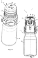
- the Fig. 2 shows the outlet assembly 22 with a protective cap 3 placed thereon.
- the illustrated protective cap 3 has a plurality of ventilation openings 30 for communicating an interior space 31 with an external environment.
- the protective cap 3 comprises a substantially cylindrical portion 32 and a cover portion 33 connected thereto.
- the ventilation openings 30 are provided on the lid portion 33.
- the number of ventilation openings 30 can be suitably selected by the person skilled in the art.
- the protective cap 3 has three uniformly distributed ventilation openings 30, of which in Fig. 1 only one is visible.
- the protective cap 3 is manufactured as an injection-molded part and has a tamper-evident seal 34 which is to be removed when it is used for the first time.
- the locking elements 35 are designed such that they prevent removal of the protective cap 3 and / or removal of the outlet assembly 22 of the container body 20 without removing the tamper-evident seal 34.
- the protective cap 3 is also designed such that a repeated removal and clamping of the protective cap 3 on the dispenser 2 is possible.
- the protective cap 3 is slightly deformed when placed, so that the elastic restoring forces of a protective cap 3 made of plastic produce a clamping action.
- locking elements are provided for this purpose.
- the protective cap 3 has a sterile filter 5 covering the ventilation openings 30, by means of which germ introduction into an interior 31 of the protective cap 3 via the ventilation openings 30 is prevented or at least reduced.
- the sterile filter 5 has a separation limit of a maximum of 0.2 .mu.m, so that bacteria with a size of about 0.2 to about 5 microns are securely retained.
- the sterile filter 5 is arranged in the illustrated embodiment parallel to the lid portion 33 of the protective cap 3 on an inner side of the lid portion 33, the ventilation openings 30 covering.
- locking arms 37 are provided in the illustrated embodiment on the cap 3 on the inside of the lid portion.
- the latching arms 37 protrude in the longitudinal direction of the protective cap 3 from the lid portion 33.
- the latching arms 37 are elastically deformed.
- a material of the sterile filter 5 is selected such that the sterile filter 5 as absorber surface for a rapid distribution of the in the region of the outlet opening 24th remaining residual drop and thus a quick drying is available.
- the sterile filter 5 is designed for this purpose as a hydrophilic polymer membrane of a membrane polymer from the group comprising polysulfone, polyethersulfone, cellulose, cellulose derivatives, polyvinylidene fluoride, polyamide, polyester, and polyacrylonitrile and / or combinations thereof.
- the illustrated sterile filter 5 is made of a material which has a sufficient rigidity, so that the sterile filter 5 can be engaged in the latching arms 37.
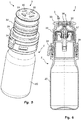
- FIGS. 3 and 4 show a discharge device 1 comprising a dispenser 2 according to Fig. 1 and a protective cap 3 similar Fig. 2 in a perspective overall view or a sectional view.
- the protective cap 3 according to 3 and 4 also essentially corresponds to the protective cap 3 according to Fig. 2 and for the same or similar components, the same reference numerals are used.
- the sterile filter 5 according to 3 and 4 attached to a carrier layer 50.
- a material of the carrier layer 50 is chosen such that the carrier layer 50 gives the associated sterile filter 5 a higher mechanical strength.
- the carrier layer 50 is also made in advantageous embodiments of a hydrophilic material, so that a sufficient moisture release over the carrier layer 50 is ensured to the environment.
- the carrier layer 50 is disposed on an outer side of the sterile filter 5 facing the environment.
- the carrier layer 50 is arranged on an inner side 31 of the protective cap 3 facing inside of the sterile filter 5.
- FIGS. 5 and 6 show a discharge device 1 comprising a dispenser 2 according to Fig. 1 and a further embodiment of a protective cap 3 similar Fig. 2 in a perspective overall view or a sectional view.
- the protective cap 3 according to FIGS. 5 and 6 also essentially corresponds to the protective cap 3 according to Fig. 2 and for the same or similar components, the same reference numerals are used.
- the protective cap 3 has four ventilation openings 30.
- the sterile filter 5 in the attached state of the protective cap 3 touches a tip of the dispenser 2 assigned to the outlet opening 24.
- the protective cap 3 according to the FIGS. 5 and 6 a protruding from the inside of the lid portion 33 stop 38.
- an additional overcap (not shown) is attached over the protective cap 3.
- the cap 3 For a fastening of this cap, not shown, the cap 3 according to the FIGS. 5 and 6 Receiving openings 39.
Description
Die Erfindung betrifft eine Austragvorrichtung zum Austrag von pharmazeutischen und/oder kosmetischen Flüssigkeiten. Ein solcher Vorrichtung ist aus
Eine in dem Flüssigkeitsreservoir bevorratete Flüssigkeit wird für einen Austrag in Richtung der Austrittsöffnung gefördert werden, wobei dies über viele verschiedene Mechanismen erfolgen kann. So kann das Flüssigkeitsreservoir als Quetschflasche ausgebildet sein, deren Inhalt durch Verformung der Wandungen unter Druck gesetzt werden kann. Auch eine separate Pumpeinrichtung ist verwendbar.A stored in the liquid reservoir liquid will be promoted for discharge in the direction of the outlet opening, which can be done via many different mechanisms. Thus, the liquid reservoir may be formed as a squeeze bottle, the content of which can be pressurized by deformation of the walls. Also, a separate pumping device is used.
Gattungsgemäße Spender sind aus dem Stand der Technik, beispielsweise aus
In jedem Fall führt das Auslassventil dazu, dass nach Schließen desselben keinerlei Flüssigkeit, welche bis in einen Abschnitt des Auslasskanals auf einer dem Flüssigkeitsreservoir abgewandten Seite des Auslassventils gelangt ist oder welche in der Umgebung der Austrittsöffnung außerhalb des Auslasskanals verblieben ist, zurück in den Spender eingesogen werden kann. Eine mögliche Kontamination des Inhaltes des Flüssigkeitsreservoirs durch zurückgesogene Flüssigkeitsreste wird dadurch verhindert. Die Restflüssigkeit verbleibt daher in einem von außen zugänglichen Bereich. Bei Kontakt mit der Atmosphäre kommt es zu einem schnellen Abtrocknen der Restflüssigkeit.In any case, the exhaust valve results in that after closing it no liquid, which has passed into a portion of the outlet channel on a side facing away from the liquid reservoir side of the outlet valve or which is left in the vicinity of the outlet opening outside the outlet channel, sucked back into the dispenser can be. A possible contamination of the contents of the liquid reservoir by liquid residues that have been sucked back is thereby prevented. The residual liquid therefore remains in an externally accessible area. Upon contact with the atmosphere, the residual liquid dries quickly.
Um auch beim Aufsetzen einer Schutzkappe auf den Spender ein rasches Abtrocknens der Restflüssigkeit zu ermöglichen, ist es aus
Gemäß
Aufgabe der Erfindung ist es, eine Austragvorrichtung zur Verfügung zu stellen, welche eine schnelle Abtrocknung erlaubt und bei welcher die Problematik eines Eindringens von Mikroorganismen in die Schutzkappe gemildert wird.
Diese Aufgabe wird durch die Gegenstände mit den Merkmalen der Ansprüche 1 und 10 gelöst. Weitere Vorteile der Erfindung ergeben sich aus den Unteransprüchen.The object of the invention is to provide a discharge device which allows rapid drying and in which the problem of microorganisms entering the protective cap is alleviated.
This object is solved by the objects with the features of claims 1 and 10. Further advantages of the invention will become apparent from the dependent claims.
Gemäß einem ersten Aspekt der Offenbarung, wird eine Schutzkappe für einen Spender zum Austrag von pharmazeutischen und/oder kosmetischen Flüssigkeiten geschaffen, wobei der Spender ein Flüssigkeitsreservoir und eine Austrittsöffnung, durch die hindurch die Flüssigkeit in eine umgebende Atmosphäre abgegeben werden kann, aufweist, und wobei die Schutzkappe mindestens eine Belüftungsöffnung zum Kommunizieren eines Innenraums mit einer äußeren Umgebung aufweist, und an der Schutzkappe ein die mindestens eine Belüftungsöffnung abdeckender Sterilfilter angeordnet ist, um einen Keimeintrag über die mindestens eine Belüftungsöffnung in den Innenraum der Schutzkappe zu reduzieren oder zu verhindern.According to a first aspect of the disclosure, there is provided a protective cap for a dispenser for dispensing pharmaceutical and / or cosmetic liquids, the dispenser having a liquid reservoir and an outlet opening through which the liquid can be dispensed into a surrounding atmosphere the protective cap has at least one ventilation opening for communicating an interior space with an external environment, and a sterile filter covering the at least one ventilation opening is arranged on the protective cap in order to reduce or prevent germination via the at least one ventilation opening into the interior of the protective cap.
Gemäß einem zweiten Aspekt der Offenbarung, wird eine Austragvorrichtung geschaffen, umfassend einen Spender zum Austrag von pharmazeutischen und/oder kosmetischen Flüssigkeiten mit einem Flüssigkeitsreservoir und einer Austrittsöffnung, durch die hindurch die Flüssigkeit in eine umgebende Atmosphäre abgegeben werden kann, und eine Schutzkappe, die mindestens eine Belüftungsöffnung zum Kommunizieren eines Innenraums mit einer äußeren Umgebung aufweist, wobei an der Schutzkappe ein die mindestens eine Belüftungsöffnung abdeckender Sterilfilter angeordnet ist, um einen Keimeintrag über die mindestens eine Belüftungsöffnung in den Innenraum der Schutzkappe zu reduzieren oder zu verhindern.According to a second aspect of the disclosure, there is provided a dispensing apparatus comprising a dispenser for dispensing pharmaceutical and / or cosmetic liquids having a liquid reservoir and an outlet opening through which the liquid can be dispensed into a surrounding atmosphere, and a protective cap which is at least a ventilation opening for communicating an interior with an external environment wherein a sterile filter covering the at least one ventilation opening is arranged on the protective cap in order to reduce or prevent germ introduction via the at least one ventilation opening into the interior of the protective cap.
Durch den Sterilfilter wird ein Keimeintrag in einen Innenraum der Schutzkappe über die mindestens eine Belüftungsöffnung verhindert oder zumindest reduziert. Als Keime oder Mikroorganismen im Sinne der vorliegenden Erfindung werden sämtliche mikrobiellen Krankheitserreger, insbesondere Bakterien und Viren, verstanden.Through the sterile filter, germ introduction into an interior of the protective cap via the at least one ventilation opening is prevented or at least reduced. As germs or microorganisms in the context of the present invention, all microbial pathogens, especially bacteria and viruses, understood.
Der Spender ist insbesondere für unkonservierte Ophthalmika geeignet. In vorteilhaften Ausgestaltungen umfasst der Spender einen Auslasskanal, der das Flüssigkeitsreservoir mit der Austrittsöffnung verbindet, und ein druckabhängig öffnendes oder manuell betätigbares Auslassventil, welches in dem Auslasskanal angeordnet ist und welches in einem geschlossenen Zustand den Auslasskanal schließt. Das Auslassventil verhindert dabei ein Eindringen von Keimen in das Flüssigkeitsreservoir. Bei dem Auslassventil handelt es sich vorzugsweise um ein druckabhängig öffnendes Auslassventil, welches durch Druckbeaufschlagung der Flüssigkeit in dem Flüssigkeitsreservoir oder einer hieraus entnommenen Teilcharge geöffnet wird und selbsttätig wieder schließt, sobald der entsprechende Überdruck gegenüber der Umgebung entfällt. Grundsätzlich sind hier jedoch auch andere Ventiltypen verwendbar. So kann beispielsweise vorgesehen sein, dass die Flüssigkeit im Flüssigkeitsreservoir permanent unter Druck steht und die Handhabung des Spenders über eine Handhabe erfolgt, deren manuelle Betätigung das Auslassventil öffnet. Das Auslassventil verhindert ein Rücksaugen ausgetragener Flüssigkeit in das Flüssigkeitsreservoir. Die mindestens eine Belüftungsöffnung bewirkt ein rasches Abtrocknen dieser Restflüssigkeit.The dispenser is particularly suitable for unpreserved ophthalmics. In advantageous embodiments, the dispenser comprises an outlet channel which connects the liquid reservoir to the outlet opening, and a pressure-dependent opening or manually operable outlet valve which is arranged in the outlet channel and which closes the outlet channel in a closed state. The outlet valve prevents penetration of germs into the liquid reservoir. The outlet valve is preferably a pressure-dependent opening outlet valve which is opened by pressurizing the liquid in the liquid reservoir or a partial charge taken from it and automatically closes again as soon as the corresponding overpressure relative to the environment is eliminated. In principle, however, other types of valves can be used here. Thus, for example, be provided that the liquid in the liquid reservoir is permanently under pressure and the handling of the dispenser via a handle, whose manual operation opens the outlet valve. The outlet valve prevents a sucked back liquid in the liquid reservoir. The at least one ventilation opening causes a rapid drying of this residual liquid.
Der Sterilfilter weist vorzugsweise einen mittleren Porendurchmesser oder eine Trenngrenze von maximal ca. 0,1 µm bis ca. 0,3 µm, vorzugsweise maximal ca. 0,2µm auf. Die Trenngrenze beschreibt, ab welcher Größe Partikel durch den Sterilfilter zurückgehalten werden. Der Sterilfilter ist vorzugsweise als Membranfilter gestaltet. Ein Membranfilter mit einer Trenngrenze zwischen ca. 0,1µm bis ca. 0,3 µm wird auch als Mikrofiltrationsmembran bezeichnet. Bakterien haben eine Größe von ca. 0.2 bis ca. 5 µm und lassen sich effizient mittels einer Mikrofiltrationsmembran herausfiltern. Je nach Anwendung können auch strengere Anforderungen an den Sterilfilter gestellt sein. Insbesondere sind in einer Ausgestaltungen Sterilfilter mit einem mittleren Porendurchmesser oder einer Trenngrenze von ca. 10 nm vorgesehen. Derartige Membranfilter werden auch als Ultrafiltrationsmembran bezeichnet. Mit einer Ultrafiltrationsmembran lassen sich auch Viren mit einer Größe von 15 nm herausfiltern. Der Sterilfilter ist in einer Ausgestaltung als Gewebe aus einem Polymer oder aus einem anorganischen Material, beispielsweise einer Keramik gefertigt. In vorteilhaften Ausgestaltungen ist der Sterilfilter als mikroporöse Polymermembran aus einem Membranpolymer aus der Gruppe umfassend Polysulfon, Polyethersulfon, Cellulose, Cellulosederivate, Polyvinylidenfluorid, Polyamid, Polyester, und Polyacrylnitril und/oder Kombinationen davon ausgebildet.The sterile filter preferably has an average pore diameter or a separation limit of at most about 0.1 .mu.m to about 0.3 .mu.m, preferably at most about 0.2 .mu.m. The separation limit describes the size at which particles are retained by the sterile filter. The sterile filter is preferably designed as a membrane filter. A membrane filter with a separation limit between about 0.1 .mu.m to about 0.3 .mu.m is also referred to as microfiltration membrane. Bacteria have a size of about 0.2 to about 5 microns and can be filtered out efficiently by means of a microfiltration membrane. Depending on the application, stricter requirements may also be imposed on the sterile filter. In particular, sterilization filters having an average pore diameter or a separation limit of approximately 10 nm are provided in one embodiment. Such membrane filters are also referred to as ultrafiltration membrane. With an ultrafiltration membrane also viruses with a size of 15 nm can be filtered out. In one embodiment, the sterile filter is fabricated from a polymer or from an inorganic material, for example a ceramic. In advantageous embodiments, the sterile filter is formed as a microporous polymer membrane from a membrane polymer from the group comprising polysulfone, polyethersulfone, cellulose, cellulose derivatives, polyvinylidene fluoride, polyamide, polyester, and polyacrylonitrile and / or combinations thereof.
Vorzugsweise dient der Sterilfilter auch als Absorberfläche, wobei über den Sterilfilter Flüssigkeit von der Austrittsöffnung weg transportiert wird und der Sterilfilter so ein schnelles Abtrocknen des Spenders vorteilhaft unterstützt. Der Sterilfilter ist zu diesem Zweck als hydrophile Polymermembran gestaltet. Die Gestaltung der Schutzkappe mit einer die Austrittsöffnung kontaktierenden Absorberfläche ist auch in Ausgestaltungen ohne Sterilfilter vorteilhaft. In einer Ausgestaltung sind zwei Membranen vorgesehen, welche als Sterilfilter bzw. Absorberfläche fungieren. In wieder anderen Ausgestaltungen ist eine mehrschichtige Membran in der Schutzkappe vorgesehen, wobei eine erste der Austrittsöffnung des Spenders zugewandte Schicht absorbierende Eigenschaften aufweist und eine zweite, der Belüftungsöffnung zugewandte Schicht Filtereigenschaften aufweist.Preferably, the sterile filter also serves as an absorber surface, whereby liquid is transported away from the outlet opening via the sterile filter and the sterile filter thus advantageously assists in rapid drying of the dispenser. The sterile filter is designed for this purpose as a hydrophilic polymer membrane. The design of the protective cap with an absorber surface contacting the outlet opening is also advantageous in embodiments without a sterile filter. In one embodiment, two membranes are provided, which act as a sterile filter or absorber surface. In yet other embodiments, a multilayer membrane is provided in the protective cap, wherein a first layer facing the outlet opening of the dispenser has absorbent properties and a second layer facing the ventilation opening has filter properties.
Der Sterilfilter ist in einer Ausgestaltung als Einlegeteil gestaltet, welches mit der Schutzkappe durch Umspritzen verbunden wird. In anderen Ausgestaltungen ist der Sterilfilter mit einer Wandung der Schutzkappe verrastet.The sterile filter is designed in one embodiment as an insert, which is connected to the protective cap by molding. In other embodiments, the sterile filter is locked with a wall of the protective cap.
In vorteilhaften Ausgestaltungen ist vorgesehen, dass die Schutzkappe einen zylindrischen Abschnitt und einen damit verbundenen Deckelabschnitt umfasst, wobei die mindestens eine Belüftungsöffnung an dem Deckelabschnitt vorgesehen ist. In einer Ausgestaltung sind an einer Innenwandung des zylindrischen Abschnitts radial nach innenweisende Rastvorsprünge oder ein umlaufender Rastvorsprung vorgesehen, durch welche(n) der Sterilfilter aufgenommen ist. In vorteilhaften Ausgestaltungen sind von einer Innenseite des Deckelabschnitts abragende Rastarme zur Befestigung des Sterilfilters vorgesehen. Derartige Rastarme erlauben eine zuverlässige, fehlerfreie Montage.In advantageous embodiments, it is provided that the protective cap comprises a cylindrical portion and a lid portion connected thereto, wherein the at least one ventilation opening is provided on the lid portion. In one embodiment, radially inwardly directed latching projections or a circumferential latching projection are provided on an inner wall of the cylindrical portion, through which (n) the sterile filter is received. In advantageous embodiments, protruding latching arms for fastening the sterile filter are provided by an inner side of the lid section. Such locking arms allow reliable, error-free installation.
In vorteilhaften Ausgestaltungen ist der Sterilfilter aus einem Material, welches eine ausreichende mechanische Festigkeit aufweist, sodass der Sterilfilter in die Rastarme oder Rastvorsprünge eingerastet werden kann. In anderen Ausgestaltungen ist der Sterilfilter auf einer Trägerschicht aufgebracht. Die Trägerschicht weist dabei in einer Ausgestaltung von dem Sterilfilter abweichende Materialeigenschaften auf. Vorzugsweise ist eine gasdurchlässige, hydrophile Trägerschicht vorgesehen, sodass die Trägerschicht ein Abtrocknen des Spenders ebenfalls unterstützt. Die Trägerschicht und der Sterilfilter sind vorzugsweise fest, insbesondere stoffschlüssig miteinander verbunden, beispielsweise verklebt oder verschweißt. In einer Ausgestaltung wird der Sterilfilter auf die Trägerschicht aufgedampft oder aufgesputtert.In advantageous embodiments of the sterile filter is made of a material which has a sufficient mechanical strength, so that the sterile filter can be engaged in the latching arms or locking projections. In other embodiments, the sterile filter is applied to a carrier layer. In one embodiment, the carrier layer has material properties deviating from the sterile filter. Preferably, a gas-permeable, hydrophilic carrier layer is provided, so that the carrier layer is a drying of the dispenser also supported. The carrier layer and the sterile filter are preferably fixed, in particular materially connected to one another, for example adhesively bonded or welded. In one embodiment, the sterile filter is vapor-deposited or sputtered onto the carrier layer.
Der Sterilfilter ist vorzugsweise derart angeordnet, dass er im Gebrauch eine Austrittsöffnung des Spenders kontaktiert, wobei insbesondere die Schutzkappe einen Anschlag aufweist, welche den Sterilfilter im Gebrauch in Kontakt mit der Austrittsöffnung zwingt. Dadurch ist eine vorteilhafte Nutzung des Sterilfilters als Absorber möglich.The sterile filter is preferably arranged such that in use it contacts an outlet opening of the dispenser, wherein in particular the protective cap has a stop which forces the sterile filter into contact with the outlet opening during use. As a result, an advantageous use of the sterile filter as an absorber is possible.
Weitere Vorteile und Aspekte der Erfindung ergeben sich außer aus den Ansprüchen auch aus der nachfolgenden Beschreibung von bevorzugten Ausführungsbeispielen der Erfindung, die nachfolgend anhand der Figuren erläutert sind. Für gleiche oder ähnliche Bauteile werden in den Zeichnungen einheitliche Bezugszeichen verwendet. Als Teil eines Ausführungsbeispiels beschriebene oder dargestellte Merkmale können ebenso in einem anderen Ausführungsbeispiel verwendet werden, um eine weitere Ausführungsform der Erfindung zu erhalten. Es zeigen:
- Fig. 1
- einen Spender zum Austrag von pharmazeutischen und/oder kosmetischen Flüssigkeiten in einer Schnittdarstellung,
- Fig. 2
- die Auslassbaugruppe gemäß
Fig. 1 mit einer Schutzkappe gemäß einem ersten Ausführungsbeispiel; - Fig. 3
- eine Austragvorrichtung umfassend einen Spender und eine Schutzkappe in einer perspektivischen Gesamtdarstellung,
- Fig. 4
- die Austragvorrichtung gemäß
Fig. 3 in einer Schnittdarstellung, - Fig. 5
- eine alternative Ausgestaltung einer Austragvorrichtung umfassend einen Spender und eine Schutzkappe in einer perspektivischen Gesamtdarstellung und
- Fig. 6
- die Austragvorrichtung gemäß
Fig. 6 in einer Schnittdarstellung.
- Fig. 1
- a dispenser for dispensing pharmaceutical and / or cosmetic liquids in a sectional view,
- Fig. 2
- the outlet assembly according to
Fig. 1 with a protective cap according to a first embodiment; - Fig. 3
- a discharge device comprising a dispenser and a protective cap in a perspective overall view,
- Fig. 4
- the discharge according to
Fig. 3 in a sectional view, - Fig. 5
- an alternative embodiment of a discharge device comprising a dispenser and a protective cap in a perspective overall view and
- Fig. 6
- the discharge according to
Fig. 6 in a sectional view.
Dieser Spender 2 verfügt über ein von einem Behälterkörper 20 begrenztes Flüssigkeitsreservoir 21. In dem Flüssigkeitsreservoir 21 ist die Flüssigkeit 4 bevorratet. Auf den Behälterkörper 20 ist eine Auslassbaugruppe 22 aufgesetzt und mittels einer Rastverbindung befestigt. Diese Auslassbaugruppe 22 dient dem Zweck, durch einen Auslasskanal 23 hindurch Flüssigkeit von dem Flüssigkeitsreservoir 21 bis zu einer Austrittsöffnung 24 zu leiten. Die dargestellte Austrittsöffnung 24 ist als Tropfenbildungsfläche gestaltet und weitet sich konisch in Austragrichtung.This
In der Darstellung der
Der dargestellte Spender 2 ist als sogenannte Drückflasche (Engl. Squeeze Bottle) gestaltet. Die Verwendung dieses Spenders 2 erfolgt derart, dass dieser in einen Überkopflage mit nach unten weisender Austrittsöffnung 24 gebracht wird. Anschließend werden Wandungen des Behälterkörpers 20 zusammengedrückt, um die Flüssigkeit 4 in dem Flüssigkeitsreservoir 21 mit einem Druck zu beaufschlagen. Dieser Druck bewirkt ein Öffnen des Auslassventils 25. Genauer wird, sobald der Flüssigkeitsdruck in einem Teilabschnitt des Auslasskanals 23 stromaufwärts des Auslassventils 25 ausreichend hoch ist, der Ventilkörper 27 durch diesen Druck entgegen der Kraft der Rückstellfeder 26 verlagert und gibt den Weg für die Flüssigkeit in Richtung der Austrittsöffnung 24 frei.The illustrated
Nach einem Austrag wird das Auslassventil 25 wieder verschlossen. Dabei verbleibt in der Regel ein Rest der Flüssigkeit, der so genannte Resttropfen, an der als Tropfenbildungsfläche gestalteten Austrittsöffnung 24 sowie in einem der Austrittsöffnung 24 zugeordneten Teilabschnitt des Auslasskanals 23 stromabwärts des Auslassventils 25 in Austragrichtung. Ein Rückfluss in das Flüssigkeitsreservoir 12 ist aufgrund des druckabhängig öffnenden Auslassventils 25 nicht möglich.After a discharge, the
Ohne Aufsetzen einer Schutzkappe, kann der Resttropfen schnell abtrocknen. Um auch bei aufgesetzter Schutzkappe ein schnelles Abtrocken zu ermöglichen, weisen gattungsgemäße Schutzkappen mindestens eine Belüftungsöffnung auf.Without putting on a protective cap, the residual droplet can dry quickly. In order to allow a quick drying even when attached protective cap, have generic protective caps on at least one vent opening.
Die
Gemäß der Anmeldung weist die Schutzkappe 3 einen die Belüftungsöffnungen 30 abdeckenden Sterilfilter 5 auf, durch welchen ein Keimeintrag in einen Innenraum 31 der Schutzkappe 3 über die Belüftungsöffnungen 30 verhindert oder zumindest verringert wird. Der Sterilfilter 5 weist eine Trenngrenze von maximal 0,2µm auf, sodass Bakterien mit einer Größe von ca. 0.2 bis ca. 5 µm sicher zurückgehalten werden.According to the application, the
Der Sterilfilter 5 ist in dem dargestellten Ausführungsbeispiel parallel zu dem Deckelabschnitt 33 der Schutzkappe 3 an einer Innenseite des Deckelabschnitts 33, die Belüftungsöffnungen 30 abdeckend angeordnet. Für eine Befestigung des Sterilfilters 5 sind in dem dargestellten Ausführungsbeispiel an der Schutzkappe 3 an der Innenseite des Deckelabschnitts 33 Rastarme 37 vorgesehen. Die Rastarme 37 ragen in Längsrichtung der Schutzkappe 3 von dem Deckelabschnitt 33 ab. Zum Anbringen des Sterilfilters 5 werden die Rastarme 37 elastisch verformt.The
Wie in
Die
Im Unterschied zu der Ausführungsform gemäß
Die
Im Unterschied zu der Ausführungsform gemäß
Wie oben beschrieben, ist in vorteilhaften Ausgestaltungen vorgesehen, dass der Sterilfilter 5 im aufgesetzten Zustand der Schutzkappe 3 eine der Austrittsöffnung 24 zugeordnete Spitze des Spenders 2 berührt. Um den Sterilfilter 5 in Kontakt mit der Spitze zu zwingen, weist die Schutzkappe 3 gemäß den
Um bei einer längerfristigen Lagerung, bei einer Lagerung in keimreicher Umgebung und/oder vor einem Erstgebrauch einen Keimeintrag und damit eine Belastung der Membran zu verringern, ist in einer Ausgestaltung vorgesehen, dass eine zusätzliche nicht dargestellte Überkappe über der Schutzkappe 3 angebracht wird. Für eine Befestigung dieser nicht dargestellten Überkappe weist die Schutzkappe 3 gemäß den
Claims (10)
- Discharging device, comprising- a dispenser (2) for discharging pharmaceutical and/or cosmetic liquids (4), having- a liquid reservoir (21) and- an exit opening (24), through which the liquid (4) can be discharged into a surrounding atmosphere, and- a protective cap (3) for repeatedly removing the protective cap (3) from the dispenser (2) and placing it thereon, which protective cap has at least one ventilation opening (30) in order for an interior to communicate with exterior surroundings,characterized in that
the protective cap (3) has arranged on it a sterile filter (5), which covers the at least one ventilation opening (30) so as to reduce, or to prevent, the introduction of germs into the interior of the protective cap (3) via the at least one ventilation opening (30). - Discharging device according to Claim 1, characterized in that the sterile filter (5) has an average pore diameter or a cutoff of at most approximately 0.1 µm to approximately 0.3 µm, preferably at most approximately 0.2 µm.
- Discharging device according to Claim 2, characterized in that the sterile filter (5) is designed in the form of a microporous polymer membrane, preferably in the form of a microporous hydrophilic polymer membrane, made of a membrane polymer from the group comprising polysulfone, polyethersulfone, cellulose, cellulose derivatives, polyvinylidene fluoride, polyamide, polyester and polyacrylonitrile and/or combinations thereof.
- Discharging device according to one of Claims 1, 2 and 3, characterized in that the sterile filter (5) is latched to a wall of the protective cap (3) .
- Discharging device according to one of Claims 1 to 4, characterized in that the protective cap (3) comprises a cylindrical portion (32) and a cover portion (33) connected thereto, wherein the at least one ventilation opening (30) is provided on the cover portion (33).
- Discharging device according to Claim 5, characterized in that latching arms (37), which project from an inner side of the cover portion, are provided for fastening the sterile filter (5).
- Discharging device according to one of Claims 1 to 6, characterized in that the sterile filter (5) is applied to a carrier layer (50).
- Discharging device according to Claim 7, characterized in that a gas-permeable, hydrophilic carrier layer (50) is provided.
- Discharging device according to one of Claims 1 to 8, characterized in that the sterile filter (5) is arranged such that, during use, it is in contact with an exit opening (24) of the dispenser (2), wherein in particular the protective cap (3) has a stop (38), which forces the sterile filter (5) into contact with the exit opening (24) during use.
- Discharging device according to one of the preceding claims, wherein the dispenser (2) has an outlet channel (23), which connects the liquid reservoir (21) to the exit opening (24), and an outlet valve (25), which opens in a pressure-dependent manner or is manually actuable, is arranged in the outlet channel (23) and, in a closed state, closes the outlet channel (23).
Applications Claiming Priority (2)
| Application Number | Priority Date | Filing Date | Title |
|---|---|---|---|
| DE102013226253.1A DE102013226253B4 (en) | 2013-12-17 | 2013-12-17 | Protective cap for a dispenser and dispenser for dispensing pharmaceutical and / or cosmetic liquids |
| PCT/EP2014/075754 WO2015090887A1 (en) | 2013-12-17 | 2014-11-27 | Protective cap for a dispenser, and dispenser for discharging pharmaceutical and/or cosmetic liquids |
Publications (2)
| Publication Number | Publication Date |
|---|---|
| EP3082707A1 EP3082707A1 (en) | 2016-10-26 |
| EP3082707B1 true EP3082707B1 (en) | 2019-01-02 |
Family
ID=51982577
Family Applications (1)
| Application Number | Title | Priority Date | Filing Date |
|---|---|---|---|
| EP14802906.9A Active EP3082707B1 (en) | 2013-12-17 | 2014-11-27 | Protective cap for a dispenser, and dispenser for discharging pharmaceutical and/or cosmetic liquids |
Country Status (6)
| Country | Link |
|---|---|
| US (2) | US20160311588A1 (en) |
| EP (1) | EP3082707B1 (en) |
| JP (1) | JP6515099B2 (en) |
| CN (1) | CN105792791B (en) |
| DE (1) | DE102013226253B4 (en) |
| WO (1) | WO2015090887A1 (en) |
Families Citing this family (17)
| Publication number | Priority date | Publication date | Assignee | Title |
|---|---|---|---|---|
| DE102011100450B8 (en) | 2011-04-27 | 2013-10-17 | Jörg Gerlach | Apparatus for spraying cells, making the apparatus, method for spraying with the apparatus and a cell suspension sprayed with the apparatus |
| FR2988015B1 (en) * | 2012-03-19 | 2015-12-11 | Rexam Healthcare La Verpillier | LIQUID DISPENSING DEVICE WITH REMOVABLE CAP |
| DE102013226253B4 (en) | 2013-12-17 | 2016-03-24 | Aptar Radolfzell Gmbh | Protective cap for a dispenser and dispenser for dispensing pharmaceutical and / or cosmetic liquids |
| JP6537319B2 (en) * | 2015-03-30 | 2019-07-03 | 東京ライト工業株式会社 | cap |
| DE102016109612B4 (en) * | 2016-05-25 | 2018-10-31 | Gerresheimer Regensburg Gmbh | Dispensing device for the metered delivery of a sterile fluid and a container for a sterile fluid |
| EP3468722B1 (en) * | 2016-06-14 | 2022-02-09 | RenovaCare Sciences Corp. | Modular device for cell spraying |
| DE102016212892C5 (en) | 2016-07-14 | 2020-01-30 | F. Holzer Gmbh | Pump head and dosing device |
| EP3576825B1 (en) * | 2017-02-01 | 2020-12-16 | Silgan Dispensing Systems Hemer GmbH | Discharge device for a liquid medium |
| FR3067011B1 (en) * | 2017-05-31 | 2019-08-02 | Nemera La Verpilliere | TIP AND DEVICE FOR DISPENSING LIQUID COMPRISING A CAP |
| EP3629781A4 (en) * | 2017-06-01 | 2021-03-10 | Counteract, LLC | Prescription bottle cap capable of administering opioid overdose reversal agent |
| IT201800002752A1 (en) | 2018-02-16 | 2019-08-16 | Lameplast Spa | CONTAINER, ESPECIALLY FOR MEDICAL, PHARMACEUTICAL, COSMETIC, FOOD OR SIMILAR PRODUCTS |
| FR3080844B1 (en) * | 2018-05-07 | 2020-06-05 | Horus Pharma | PACKAGING AND DISPENSING DEVICE OF A PRODUCT WITH BOTTLE AND METERING CAP WITH FILTER |
| JP7405835B2 (en) * | 2018-08-31 | 2023-12-26 | フジフイルム アーバイン サイエンティフィック, インコーポレイテッド | Filter unit for mixing equipment and method for filtering solutions |
| WO2020174421A1 (en) * | 2019-02-26 | 2020-09-03 | 3M Innovative Properties Company | A system and method for prepping liquid |
| EP3730101A1 (en) | 2019-04-26 | 2020-10-28 | Aptar Radolfzell GmbH | Vented protective cap for a liquid dispenser |
| CN111572988A (en) * | 2020-05-19 | 2020-08-25 | 深圳市通产丽星科技集团有限公司 | Packaging container |
| ES2952019T3 (en) * | 2020-05-25 | 2023-10-26 | Serve Sterile Pc | Product with a non-alcoholic beverage and method of preserving said beverage |
Citations (7)
| Publication number | Priority date | Publication date | Assignee | Title |
|---|---|---|---|---|
| GB2132989A (en) | 1983-01-07 | 1984-07-18 | Gelman Sciences Inc | Hand-held liquid filtering and dispensing device |
| US4929354A (en) | 1982-05-28 | 1990-05-29 | Cuno, Incorporated | Filter element having microporous membrane |
| US5105993A (en) | 1989-12-29 | 1992-04-21 | La Haye Laboratories, Inc. | Disposable medical dispenser with a filtering dispenser nozzle |
| US20040200860A1 (en) | 2003-04-09 | 2004-10-14 | Ursapharm Arzneimittel Gmbh & Co. Kg | Fluid dispenser |
| DE102011086755A1 (en) | 2011-11-21 | 2013-05-23 | Aptar Radolfzell Gmbh | Dispenser for dispensing pharmaceutical liquids |
| WO2013140069A1 (en) * | 2012-03-19 | 2013-09-26 | Rexam Healthcare La Verpilliere | Liquid dispensing device equipped with a removable cap |
| WO2015090887A1 (en) | 2013-12-17 | 2015-06-25 | Aptar Radolfzell Gmbh | Protective cap for a dispenser, and dispenser for discharging pharmaceutical and/or cosmetic liquids |
Family Cites Families (69)
| Publication number | Priority date | Publication date | Assignee | Title |
|---|---|---|---|---|
| US3622049A (en) * | 1969-05-05 | 1971-11-23 | Schering Corp | Dispensing system |
| JPS5811717Y2 (en) * | 1979-04-09 | 1983-03-05 | 有限会社 コンペツクス | breathable cap sheet |
| US4463880A (en) * | 1982-04-30 | 1984-08-07 | The Regents Of The University Of California | Medicine drop dispenser with anti-bacterial filter |
| US4696409A (en) * | 1986-06-13 | 1987-09-29 | Caterpillar Inc. | Vented fuel tank cap assembly |
| US4938389A (en) * | 1988-11-03 | 1990-07-03 | Eye Research Institute Of Retina Foundation | Filter bottle |
| US4957518A (en) * | 1989-06-06 | 1990-09-18 | Brassell Gilbert W | Assembly useful for retaining components such as a filter to a container and a corresponding combination |
| US5496471A (en) * | 1990-01-08 | 1996-03-05 | Ciba-Geigy Corporation | Apparatus for removing components from solutions |
| US5080800A (en) * | 1990-01-08 | 1992-01-14 | Ciba-Geigy Corporation | Process for removing components from solutions |
| US5033647A (en) * | 1990-03-09 | 1991-07-23 | Allergan, Inc. | Value controlled squeezable fluid dispenser |
| US5154325A (en) * | 1991-01-09 | 1992-10-13 | Ryder International Corporation | Solution delivery nozzle and system with antimicrobial features |
| US6000580A (en) | 1992-06-03 | 1999-12-14 | Astra Aktielbolag | Device for dispensing preservative-free nasal sprays and similar preparations |
| SE9201718D0 (en) | 1992-06-03 | 1992-06-03 | Astra Ab | NASAL SPRAY DEVICE |
| US5328063A (en) * | 1993-06-10 | 1994-07-12 | Creative Packaging Corp. | Venting closure cap |
| US5437655A (en) * | 1993-09-03 | 1995-08-01 | B. Braun Medical Inc. | Air inlet filter for burette top |
| US5849311A (en) * | 1996-10-28 | 1998-12-15 | Biopolymerix, Inc. | Contact-killing non-leaching antimicrobial materials |
| DE69420862T2 (en) * | 1993-12-20 | 2000-05-18 | Biopolymerix Inc | LIQUID DISPENSOR FOR DISPENSING STERILE LIQUID |
| US5817325A (en) * | 1996-10-28 | 1998-10-06 | Biopolymerix, Inc. | Contact-killing antimicrobial devices |
| US5611464A (en) * | 1995-05-30 | 1997-03-18 | Ciba Geigy Corporation | Container for preserving media in the tip of a solution dispenser |
| FR2738555B1 (en) | 1995-09-13 | 1998-08-21 | Sofab | IMPROVEMENTS TO A DISPENSING DEVICE FOR OPHTHALMOLOGICAL PRODUCTS |
| US6053368A (en) | 1995-11-17 | 2000-04-25 | Ursatec Verpackung-Gmbh | Anti-contamination dispensing apparatus for fluids |
| DE29518284U1 (en) * | 1995-11-17 | 1996-02-08 | Ursatec Verpackungs Gmbh | Contamination protective dispenser for fluids |
| US5988426A (en) * | 1996-11-08 | 1999-11-23 | Stern; Brett | Leakproof vented beverage lid |
| FR2761665B1 (en) * | 1997-04-02 | 1999-06-25 | Sofab | DEVICE FOR DISPENSING AND PACKAGING STERILE LIQUID PRODUCTS |
| FR2772007B1 (en) * | 1997-12-08 | 2000-02-04 | Sivel | DEVICE FOR CONDITIONING AND DISPENSING A PRODUCT, WITH MANUAL PUMP AND CONTAINER WITH AIR INLET FILTER IN THE CONTAINER |
| US6180584B1 (en) * | 1998-02-12 | 2001-01-30 | Surfacine Development Company, Llc | Disinfectant composition providing sustained residual biocidal action |
| US7799009B2 (en) * | 2000-01-24 | 2010-09-21 | Bracco Diagnostics Inc. | Tabletop drug dispensing vial access adapter |
| US6551608B2 (en) * | 2000-03-06 | 2003-04-22 | Porex Technologies Corporation | Porous plastic media with antiviral or antimicrobial properties and processes for making the same |
| JP4580524B2 (en) * | 2000-09-12 | 2010-11-17 | 株式会社日本点眼薬研究所 | Discharge container with filter |
| FR2816600B1 (en) * | 2000-11-13 | 2003-03-21 | Michel Faurie | DISPENSING DEVICE FOR DROP FLUID LIQUIDS |
| US6904929B2 (en) * | 2001-06-26 | 2005-06-14 | Filtertek Inc. | Check valve and filter assembly incorporating such valve, especially for water cooler assemblies |
| US7011221B2 (en) * | 2002-01-02 | 2006-03-14 | Erie Plastics Corporation | Anti-leak dust cover and closure used therewith |
| DE10200519A1 (en) | 2002-01-09 | 2003-07-10 | Neomed Holding Sa Luxemburg Lu | Valve |
| JP4047617B2 (en) * | 2002-04-04 | 2008-02-13 | ニプロ株式会社 | Chemical container |
| KR100660676B1 (en) | 2002-04-04 | 2006-12-21 | 니프로 가부시키가이샤 | Chemical container |
| JP4744775B2 (en) * | 2002-11-20 | 2011-08-10 | ニプロ株式会社 | Chemical container |
| DE20207474U1 (en) * | 2002-05-13 | 2002-08-08 | Dagn Josef | Sealing cap, in particular for closing an oil filter connection |
| US20040129648A1 (en) * | 2002-07-23 | 2004-07-08 | Manesis Nick J. | Antimicrobial matrix and method of use |
| EP1622813A4 (en) * | 2003-03-31 | 2009-12-30 | Nick J Manesis | Multi-dose liquid dispensing assembly |
| US8499985B2 (en) * | 2003-05-28 | 2013-08-06 | Robert A. Lehmkuhl | Automatic dispensing cap for squeezable bottle |
| JP4615445B2 (en) * | 2003-09-02 | 2011-01-19 | 大塚製薬株式会社 | Discharge container and eye drop container |
| US20060011654A1 (en) * | 2004-07-16 | 2006-01-19 | Webb Garth T | Disinfectant cap for sterile liquid dispenser |
| US9004317B2 (en) * | 2004-07-20 | 2015-04-14 | Sivel | Product packaging and dispensing device comprising a sterile filter bottle which is equipped with a nozzle |
| FR2873358B1 (en) * | 2004-07-20 | 2006-11-10 | Sivel Soc Civ Ile | DEVICE FOR PACKAGING AND DISPENSING A PRODUCT WITH A STERILE FILTER BOTTLE WITH A TIP |
| US8057567B2 (en) * | 2004-11-05 | 2011-11-15 | Donaldson Company, Inc. | Filter medium and breather filter structure |
| US20100108712A1 (en) * | 2005-09-30 | 2010-05-06 | Manesis Nick J | Multi-dose liquid dispensing assembly |
| EP1779933A1 (en) | 2005-10-26 | 2007-05-02 | The Procter and Gamble Company | Dispenser for a liquid |
| FR2897599B1 (en) * | 2006-02-23 | 2010-08-27 | Rexam Pharma | LIQUID CONDITIONING AND DISPENSING ASSEMBLY. |
| US7628298B2 (en) * | 2007-02-28 | 2009-12-08 | Berry Plastics Corporation | Aerosol overcap with evaporation vent |
| ITRM20070275A1 (en) * | 2007-05-17 | 2008-11-18 | Federighi Federigo | MULTIDOSE DISPENSER BOTTLE FOR PRESERVATIVE-FREE LIQUID PREPARATIONS. |
| ATE556000T1 (en) * | 2007-06-13 | 2012-05-15 | M & R Consulting Services | ELECTROCHEMICAL DISPENSER |
| JP5570753B2 (en) | 2008-07-08 | 2014-08-13 | 株式会社ダイセル | Filter material made of porous silica and cigarette filter using the same |
| FR2934572A1 (en) * | 2008-07-31 | 2010-02-05 | Thea Lab | BOTTLE FOR FLASK OF LIQUID CONDITIONING TO DISPENSE DROP GOUTTE. |
| CN102006925B (en) * | 2009-02-16 | 2014-10-08 | 住友电工超效能高分子股份有限公司 | Porous multilayer filter and method for producing same |
| US8523020B2 (en) * | 2009-02-25 | 2013-09-03 | Digital Innovations Llc | Vented dispensing device |
| US20120104113A1 (en) * | 2009-02-25 | 2012-05-03 | Digital Innovations, Llc | Vented Dispensing Device |
| GB201019769D0 (en) * | 2010-11-22 | 2011-01-05 | Greif Int Holding Bv | Vented container closure |
| CN102079415B (en) * | 2010-12-23 | 2012-09-05 | 蒋一新 | Container for sucking beverage |
| DE102013211423A1 (en) * | 2013-06-18 | 2014-12-31 | Aptar Radolfzell Gmbh | Multilayer container |
| US9669974B2 (en) * | 2013-12-17 | 2017-06-06 | Aptar Radolfzell Gmbh | Protective cap for a dispenser, and discharge device for discharging pharmaceutical and/or cosmetical liquids |
| US9676525B2 (en) * | 2013-12-17 | 2017-06-13 | Aptar Radolfzell Gmbh | Protective cap for a dispenser, and discharge device for discharging pharmaceutical and/or cosmetical liquids |
| DE102013226250B4 (en) * | 2013-12-17 | 2019-07-18 | Aptar Radolfzell Gmbh | Protective cap for a dispenser and dispenser comprising a dispenser for dispensing pharmaceutical and / or cosmetic liquids |
| US10604420B2 (en) * | 2013-12-18 | 2020-03-31 | Brita Lp | Method and apparatus for reservoir free and ventless water filtering |
| US20150360156A1 (en) * | 2013-12-20 | 2015-12-17 | Hollingsworth & Vose Company | Filter media and elements with fine staple fibers |
| JP6453537B2 (en) * | 2013-12-27 | 2019-01-16 | 日東電工株式会社 | Moisture permeable filter media |
| FR3018704B1 (en) * | 2014-03-20 | 2016-03-18 | Rexam Healthcare La Verpillier | LIQUID DISPENSING DEVICE COMPRISING A PROTECTIVE CAP. |
| US20150352809A1 (en) * | 2014-06-06 | 2015-12-10 | Milliken & Company | Cementitious composite |
| US10377539B2 (en) * | 2015-09-17 | 2019-08-13 | Performance Systematix, Inc. | Filter cap assembly including protective baffle and method of use |
| US10351320B2 (en) * | 2015-09-17 | 2019-07-16 | Performance Systematix, Inc. | Filter cap assembly including protective baffle and method of use |
| DE102016210992B3 (en) * | 2016-06-20 | 2017-05-11 | Aptar Radolfzell Gmbh | liquid dispenser |
-
2013
- 2013-12-17 DE DE102013226253.1A patent/DE102013226253B4/en active Active
-
2014
- 2014-11-27 EP EP14802906.9A patent/EP3082707B1/en active Active
- 2014-11-27 JP JP2016535220A patent/JP6515099B2/en active Active
- 2014-11-27 CN CN201480067574.9A patent/CN105792791B/en active Active
- 2014-11-27 US US15/102,415 patent/US20160311588A1/en not_active Abandoned
- 2014-11-27 WO PCT/EP2014/075754 patent/WO2015090887A1/en active Application Filing
-
2020
- 2020-04-17 US US16/851,516 patent/US11059639B2/en active Active
Patent Citations (9)
| Publication number | Priority date | Publication date | Assignee | Title |
|---|---|---|---|---|
| US4929354A (en) | 1982-05-28 | 1990-05-29 | Cuno, Incorporated | Filter element having microporous membrane |
| GB2132989A (en) | 1983-01-07 | 1984-07-18 | Gelman Sciences Inc | Hand-held liquid filtering and dispensing device |
| US5105993A (en) | 1989-12-29 | 1992-04-21 | La Haye Laboratories, Inc. | Disposable medical dispenser with a filtering dispenser nozzle |
| US20040200860A1 (en) | 2003-04-09 | 2004-10-14 | Ursapharm Arzneimittel Gmbh & Co. Kg | Fluid dispenser |
| DE102011086755A1 (en) | 2011-11-21 | 2013-05-23 | Aptar Radolfzell Gmbh | Dispenser for dispensing pharmaceutical liquids |
| WO2013140069A1 (en) * | 2012-03-19 | 2013-09-26 | Rexam Healthcare La Verpilliere | Liquid dispensing device equipped with a removable cap |
| US20150043958A1 (en) | 2012-03-19 | 2015-02-12 | Nemera La Verpillière S.A.S. | Liquid Dispensing Device Equipped With A Removable Cap |
| WO2015090887A1 (en) | 2013-12-17 | 2015-06-25 | Aptar Radolfzell Gmbh | Protective cap for a dispenser, and dispenser for discharging pharmaceutical and/or cosmetic liquids |
| EP3082707A1 (en) | 2013-12-17 | 2016-10-26 | Aptar Radolfzell GmbH | Protective cap for a dispenser, and dispenser for discharging pharmaceutical and/or cosmetic liquids |
Also Published As
| Publication number | Publication date |
|---|---|
| US20200262622A1 (en) | 2020-08-20 |
| DE102013226253A1 (en) | 2015-06-18 |
| US20160311588A1 (en) | 2016-10-27 |
| EP3082707A1 (en) | 2016-10-26 |
| JP6515099B2 (en) | 2019-05-15 |
| DE102013226253B4 (en) | 2016-03-24 |
| CN105792791B (en) | 2019-09-10 |
| WO2015090887A1 (en) | 2015-06-25 |
| JP2017507081A (en) | 2017-03-16 |
| CN105792791A (en) | 2016-07-20 |
| US11059639B2 (en) | 2021-07-13 |
Similar Documents
| Publication | Publication Date | Title |
|---|---|---|
| EP3082707B1 (en) | Protective cap for a dispenser, and dispenser for discharging pharmaceutical and/or cosmetic liquids | |
| EP3083434B1 (en) | Protective cap for a dispenser and dispenser for discharging pharmaceutical and/or cosmetic liquids | |
| DE102014201696A1 (en) | Protective cap for a dispenser and dispensing device for dispensing pharmaceutical and / or cosmetic liquids | |
| DE102014201697A1 (en) | Protective cap for a dispenser and dispensing device for dispensing pharmaceutical and / or cosmetic liquids | |
| EP0190169B1 (en) | Container provided with a closure | |
| DE102016210992B3 (en) | liquid dispenser | |
| EP3978389B1 (en) | Liquid dispenser, in particular drop dispenser | |
| CH708662A1 (en) | And capsule system for preparing a liquid food. | |
| WO2012104351A1 (en) | Functional head for a fragrance container | |
| WO2000020293A1 (en) | Self-closing valve arrangement for the dispensing opening of a container | |
| DE69915783T2 (en) | donor | |
| WO2018103906A1 (en) | Stopper for a container for use in freeze-drying processes, and assembly of a stopper and a container | |
| DE102013003851B3 (en) | Stopper, particularly lyo-stopper for sealing vial filled with medicinal products to be freeze-dried in sterile room, has particle barrier provided in flow channel, which prevents discharge of particles of product material contained in vial | |
| DE202011051640U1 (en) | Collection tank for lubricants | |
| WO2002090211A1 (en) | Container arrangement for removing and applying partial amounts of a liquid product | |
| WO2012041614A1 (en) | Discharge device having a compressible media container | |
| DE19753592A1 (en) | Sealing cover | |
| WO2017108156A1 (en) | Air freshener apparatus for a vehicle | |
| DE102011106382A1 (en) | Filter element for a filter device of a motor vehicle and filter device with the filter element | |
| EP2337718B1 (en) | Pneumatic ventilation valve | |
| EP3736049A1 (en) | Discharge head and liquid dispenser with a discharge head | |
| EP2742268B1 (en) | Device for admitting air to, and extracting air from, an oil tank | |
| DE10230748C1 (en) | Valve for an evacuated foodstuff container is on a hinge mounting at the container lid, with a membrane between the valve housing and its cover with a tongue as a non-return valve | |
| DE102019105161A1 (en) | Irritant cartridge and irritant spray device | |
| DE102016109612A1 (en) | Dispensing device for metered delivery of a sterile fluid |
Legal Events
| Date | Code | Title | Description |
|---|---|---|---|
| TPAC | Observations filed by third parties |
Free format text: ORIGINAL CODE: EPIDOSNTIPA |
|
| PUAI | Public reference made under article 153(3) epc to a published international application that has entered the european phase |
Free format text: ORIGINAL CODE: 0009012 |
|
| 17P | Request for examination filed |
Effective date: 20160617 |
|
| AK | Designated contracting states |
Kind code of ref document: A1 Designated state(s): AL AT BE BG CH CY CZ DE DK EE ES FI FR GB GR HR HU IE IS IT LI LT LU LV MC MK MT NL NO PL PT RO RS SE SI SK SM TR |
|
| AX | Request for extension of the european patent |
Extension state: BA ME |
|
| DAX | Request for extension of the european patent (deleted) | ||
| STAA | Information on the status of an ep patent application or granted ep patent |
Free format text: STATUS: EXAMINATION IS IN PROGRESS |
|
| 17Q | First examination report despatched |
Effective date: 20180221 |
|
| GRAP | Despatch of communication of intention to grant a patent |
Free format text: ORIGINAL CODE: EPIDOSNIGR1 |
|
| STAA | Information on the status of an ep patent application or granted ep patent |
Free format text: STATUS: GRANT OF PATENT IS INTENDED |
|
| INTG | Intention to grant announced |
Effective date: 20181005 |
|
| GRAS | Grant fee paid |
Free format text: ORIGINAL CODE: EPIDOSNIGR3 |
|
| GRAA | (expected) grant |
Free format text: ORIGINAL CODE: 0009210 |
|
| STAA | Information on the status of an ep patent application or granted ep patent |
Free format text: STATUS: THE PATENT HAS BEEN GRANTED |
|
| AK | Designated contracting states |
Kind code of ref document: B1 Designated state(s): AL AT BE BG CH CY CZ DE DK EE ES FI FR GB GR HR HU IE IS IT LI LT LU LV MC MK MT NL NO PL PT RO RS SE SI SK SM TR |
|
| REG | Reference to a national code |
Ref country code: GB Ref legal event code: FG4D Free format text: NOT ENGLISH |
|
| REG | Reference to a national code |
Ref country code: CH Ref legal event code: EP Ref country code: AT Ref legal event code: REF Ref document number: 1083462 Country of ref document: AT Kind code of ref document: T Effective date: 20190115 |
|
| REG | Reference to a national code |
Ref country code: DE Ref legal event code: R096 Ref document number: 502014010557 Country of ref document: DE |
|
| REG | Reference to a national code |
Ref country code: IE Ref legal event code: FG4D Free format text: LANGUAGE OF EP DOCUMENT: GERMAN |
|
| REG | Reference to a national code |
Ref country code: CH Ref legal event code: NV Representative=s name: DR. LUSUARDI AG, CH |
|
| REG | Reference to a national code |
Ref country code: NL Ref legal event code: MP Effective date: 20190102 |
|
| REG | Reference to a national code |
Ref country code: LT Ref legal event code: MG4D |
|
| PG25 | Lapsed in a contracting state [announced via postgrant information from national office to epo] |
Ref country code: NL Free format text: LAPSE BECAUSE OF FAILURE TO SUBMIT A TRANSLATION OF THE DESCRIPTION OR TO PAY THE FEE WITHIN THE PRESCRIBED TIME-LIMIT Effective date: 20190102 |
|
| PG25 | Lapsed in a contracting state [announced via postgrant information from national office to epo] |
Ref country code: LT Free format text: LAPSE BECAUSE OF FAILURE TO SUBMIT A TRANSLATION OF THE DESCRIPTION OR TO PAY THE FEE WITHIN THE PRESCRIBED TIME-LIMIT Effective date: 20190102 Ref country code: PL Free format text: LAPSE BECAUSE OF FAILURE TO SUBMIT A TRANSLATION OF THE DESCRIPTION OR TO PAY THE FEE WITHIN THE PRESCRIBED TIME-LIMIT Effective date: 20190102 Ref country code: ES Free format text: LAPSE BECAUSE OF FAILURE TO SUBMIT A TRANSLATION OF THE DESCRIPTION OR TO PAY THE FEE WITHIN THE PRESCRIBED TIME-LIMIT Effective date: 20190102 Ref country code: FI Free format text: LAPSE BECAUSE OF FAILURE TO SUBMIT A TRANSLATION OF THE DESCRIPTION OR TO PAY THE FEE WITHIN THE PRESCRIBED TIME-LIMIT Effective date: 20190102 Ref country code: NO Free format text: LAPSE BECAUSE OF FAILURE TO SUBMIT A TRANSLATION OF THE DESCRIPTION OR TO PAY THE FEE WITHIN THE PRESCRIBED TIME-LIMIT Effective date: 20190402 Ref country code: PT Free format text: LAPSE BECAUSE OF FAILURE TO SUBMIT A TRANSLATION OF THE DESCRIPTION OR TO PAY THE FEE WITHIN THE PRESCRIBED TIME-LIMIT Effective date: 20190502 Ref country code: SE Free format text: LAPSE BECAUSE OF FAILURE TO SUBMIT A TRANSLATION OF THE DESCRIPTION OR TO PAY THE FEE WITHIN THE PRESCRIBED TIME-LIMIT Effective date: 20190102 |
|
| PG25 | Lapsed in a contracting state [announced via postgrant information from national office to epo] |
Ref country code: LV Free format text: LAPSE BECAUSE OF FAILURE TO SUBMIT A TRANSLATION OF THE DESCRIPTION OR TO PAY THE FEE WITHIN THE PRESCRIBED TIME-LIMIT Effective date: 20190102 Ref country code: IS Free format text: LAPSE BECAUSE OF FAILURE TO SUBMIT A TRANSLATION OF THE DESCRIPTION OR TO PAY THE FEE WITHIN THE PRESCRIBED TIME-LIMIT Effective date: 20190502 Ref country code: BG Free format text: LAPSE BECAUSE OF FAILURE TO SUBMIT A TRANSLATION OF THE DESCRIPTION OR TO PAY THE FEE WITHIN THE PRESCRIBED TIME-LIMIT Effective date: 20190402 Ref country code: RS Free format text: LAPSE BECAUSE OF FAILURE TO SUBMIT A TRANSLATION OF THE DESCRIPTION OR TO PAY THE FEE WITHIN THE PRESCRIBED TIME-LIMIT Effective date: 20190102 Ref country code: HR Free format text: LAPSE BECAUSE OF FAILURE TO SUBMIT A TRANSLATION OF THE DESCRIPTION OR TO PAY THE FEE WITHIN THE PRESCRIBED TIME-LIMIT Effective date: 20190102 Ref country code: GR Free format text: LAPSE BECAUSE OF FAILURE TO SUBMIT A TRANSLATION OF THE DESCRIPTION OR TO PAY THE FEE WITHIN THE PRESCRIBED TIME-LIMIT Effective date: 20190403 |
|
| REG | Reference to a national code |
Ref country code: DE Ref legal event code: R026 Ref document number: 502014010557 Country of ref document: DE |
|
| PLBI | Opposition filed |
Free format text: ORIGINAL CODE: 0009260 |
|
| PLAX | Notice of opposition and request to file observation + time limit sent |
Free format text: ORIGINAL CODE: EPIDOSNOBS2 |
|
| PG25 | Lapsed in a contracting state [announced via postgrant information from national office to epo] |
Ref country code: AL Free format text: LAPSE BECAUSE OF FAILURE TO SUBMIT A TRANSLATION OF THE DESCRIPTION OR TO PAY THE FEE WITHIN THE PRESCRIBED TIME-LIMIT Effective date: 20190102 Ref country code: CZ Free format text: LAPSE BECAUSE OF FAILURE TO SUBMIT A TRANSLATION OF THE DESCRIPTION OR TO PAY THE FEE WITHIN THE PRESCRIBED TIME-LIMIT Effective date: 20190102 Ref country code: SK Free format text: LAPSE BECAUSE OF FAILURE TO SUBMIT A TRANSLATION OF THE DESCRIPTION OR TO PAY THE FEE WITHIN THE PRESCRIBED TIME-LIMIT Effective date: 20190102 Ref country code: RO Free format text: LAPSE BECAUSE OF FAILURE TO SUBMIT A TRANSLATION OF THE DESCRIPTION OR TO PAY THE FEE WITHIN THE PRESCRIBED TIME-LIMIT Effective date: 20190102 Ref country code: DK Free format text: LAPSE BECAUSE OF FAILURE TO SUBMIT A TRANSLATION OF THE DESCRIPTION OR TO PAY THE FEE WITHIN THE PRESCRIBED TIME-LIMIT Effective date: 20190102 Ref country code: EE Free format text: LAPSE BECAUSE OF FAILURE TO SUBMIT A TRANSLATION OF THE DESCRIPTION OR TO PAY THE FEE WITHIN THE PRESCRIBED TIME-LIMIT Effective date: 20190102 |
|
| 26 | Opposition filed |
Opponent name: EPPING HERMANN FISCHER PATENTANWALTGESELLSCHAFT MB Effective date: 20191001 |
|
| PG25 | Lapsed in a contracting state [announced via postgrant information from national office to epo] |
Ref country code: SM Free format text: LAPSE BECAUSE OF FAILURE TO SUBMIT A TRANSLATION OF THE DESCRIPTION OR TO PAY THE FEE WITHIN THE PRESCRIBED TIME-LIMIT Effective date: 20190102 |
|
| PLBB | Reply of patent proprietor to notice(s) of opposition received |
Free format text: ORIGINAL CODE: EPIDOSNOBS3 |
|
| PG25 | Lapsed in a contracting state [announced via postgrant information from national office to epo] |
Ref country code: SI Free format text: LAPSE BECAUSE OF FAILURE TO SUBMIT A TRANSLATION OF THE DESCRIPTION OR TO PAY THE FEE WITHIN THE PRESCRIBED TIME-LIMIT Effective date: 20190102 |
|
| PG25 | Lapsed in a contracting state [announced via postgrant information from national office to epo] |
Ref country code: TR Free format text: LAPSE BECAUSE OF FAILURE TO SUBMIT A TRANSLATION OF THE DESCRIPTION OR TO PAY THE FEE WITHIN THE PRESCRIBED TIME-LIMIT Effective date: 20190102 |
|
| PG25 | Lapsed in a contracting state [announced via postgrant information from national office to epo] |
Ref country code: LU Free format text: LAPSE BECAUSE OF NON-PAYMENT OF DUE FEES Effective date: 20191127 Ref country code: MC Free format text: LAPSE BECAUSE OF FAILURE TO SUBMIT A TRANSLATION OF THE DESCRIPTION OR TO PAY THE FEE WITHIN THE PRESCRIBED TIME-LIMIT Effective date: 20190102 |
|
| REG | Reference to a national code |
Ref country code: BE Ref legal event code: MM Effective date: 20191130 |
|
| PG25 | Lapsed in a contracting state [announced via postgrant information from national office to epo] |
Ref country code: IE Free format text: LAPSE BECAUSE OF NON-PAYMENT OF DUE FEES Effective date: 20191127 |
|
| PG25 | Lapsed in a contracting state [announced via postgrant information from national office to epo] |
Ref country code: BE Free format text: LAPSE BECAUSE OF NON-PAYMENT OF DUE FEES Effective date: 20191130 |
|
| REG | Reference to a national code |
Ref country code: AT Ref legal event code: MM01 Ref document number: 1083462 Country of ref document: AT Kind code of ref document: T Effective date: 20191127 |
|
| PG25 | Lapsed in a contracting state [announced via postgrant information from national office to epo] |
Ref country code: AT Free format text: LAPSE BECAUSE OF NON-PAYMENT OF DUE FEES Effective date: 20191127 |
|
| PLCK | Communication despatched that opposition was rejected |
Free format text: ORIGINAL CODE: EPIDOSNREJ1 |
|
| APAH | Appeal reference modified |
Free format text: ORIGINAL CODE: EPIDOSCREFNO |
|
| APBM | Appeal reference recorded |
Free format text: ORIGINAL CODE: EPIDOSNREFNO |
|
| APBP | Date of receipt of notice of appeal recorded |
Free format text: ORIGINAL CODE: EPIDOSNNOA2O |
|
| PG25 | Lapsed in a contracting state [announced via postgrant information from national office to epo] |
Ref country code: CY Free format text: LAPSE BECAUSE OF FAILURE TO SUBMIT A TRANSLATION OF THE DESCRIPTION OR TO PAY THE FEE WITHIN THE PRESCRIBED TIME-LIMIT Effective date: 20190102 |
|
| APBQ | Date of receipt of statement of grounds of appeal recorded |
Free format text: ORIGINAL CODE: EPIDOSNNOA3O |
|
| PG25 | Lapsed in a contracting state [announced via postgrant information from national office to epo] |
Ref country code: MT Free format text: LAPSE BECAUSE OF FAILURE TO SUBMIT A TRANSLATION OF THE DESCRIPTION OR TO PAY THE FEE WITHIN THE PRESCRIBED TIME-LIMIT Effective date: 20190102 Ref country code: HU Free format text: LAPSE BECAUSE OF FAILURE TO SUBMIT A TRANSLATION OF THE DESCRIPTION OR TO PAY THE FEE WITHIN THE PRESCRIBED TIME-LIMIT; INVALID AB INITIO Effective date: 20141127 |
|
| REG | Reference to a national code |
Ref country code: DE Ref legal event code: R082 Ref document number: 502014010557 Country of ref document: DE Representative=s name: WITTE, WELLER & PARTNER PATENTANWAELTE MBB, DE |
|
| PG25 | Lapsed in a contracting state [announced via postgrant information from national office to epo] |
Ref country code: MK Free format text: LAPSE BECAUSE OF FAILURE TO SUBMIT A TRANSLATION OF THE DESCRIPTION OR TO PAY THE FEE WITHIN THE PRESCRIBED TIME-LIMIT Effective date: 20190102 |
|
| P01 | Opt-out of the competence of the unified patent court (upc) registered |
Effective date: 20230502 |
|
| APBU | Appeal procedure closed |
Free format text: ORIGINAL CODE: EPIDOSNNOA9O |
|
| REG | Reference to a national code |
Ref country code: DE Ref legal event code: R100 Ref document number: 502014010557 Country of ref document: DE |
|
| PLBP | Opposition withdrawn |
Free format text: ORIGINAL CODE: 0009264 |
|
| PLBN | Opposition rejected |
Free format text: ORIGINAL CODE: 0009273 |
|
| STAA | Information on the status of an ep patent application or granted ep patent |
Free format text: STATUS: OPPOSITION REJECTED |
|
| 27O | Opposition rejected |
Effective date: 20231010 |
|
| PGFP | Annual fee paid to national office [announced via postgrant information from national office to epo] |
Ref country code: GB Payment date: 20231123 Year of fee payment: 10 |
|
| PGFP | Annual fee paid to national office [announced via postgrant information from national office to epo] |
Ref country code: IT Payment date: 20231130 Year of fee payment: 10 Ref country code: FR Payment date: 20231122 Year of fee payment: 10 Ref country code: DE Payment date: 20231004 Year of fee payment: 10 Ref country code: CH Payment date: 20231201 Year of fee payment: 10 |