EP3082232A1 - Electronic control unit, electric power steering device, and vehicle - Google Patents
Electronic control unit, electric power steering device, and vehicle Download PDFInfo
- Publication number
- EP3082232A1 EP3082232A1 EP14869940.8A EP14869940A EP3082232A1 EP 3082232 A1 EP3082232 A1 EP 3082232A1 EP 14869940 A EP14869940 A EP 14869940A EP 3082232 A1 EP3082232 A1 EP 3082232A1
- Authority
- EP
- European Patent Office
- Prior art keywords
- phase
- output
- terminal
- board
- conductor pattern
- Prior art date
- Legal status (The legal status is an assumption and is not a legal conclusion. Google has not performed a legal analysis and makes no representation as to the accuracy of the status listed.)
- Granted
Links
- 239000004020 conductor Substances 0.000 claims abstract description 115
- 238000005304 joining Methods 0.000 abstract description 9
- 238000004804 winding Methods 0.000 description 29
- 238000001514 detection method Methods 0.000 description 18
- 230000008878 coupling Effects 0.000 description 14
- 238000010168 coupling process Methods 0.000 description 14
- 238000005859 coupling reaction Methods 0.000 description 14
- 230000005856 abnormality Effects 0.000 description 12
- 238000005476 soldering Methods 0.000 description 10
- 239000003990 capacitor Substances 0.000 description 9
- 238000005452 bending Methods 0.000 description 8
- 230000005669 field effect Effects 0.000 description 4
- 230000007246 mechanism Effects 0.000 description 4
- 229910052751 metal Inorganic materials 0.000 description 3
- 239000002184 metal Substances 0.000 description 3
- 230000009467 reduction Effects 0.000 description 3
- 230000001133 acceleration Effects 0.000 description 2
- 238000005520 cutting process Methods 0.000 description 2
- 238000006073 displacement reaction Methods 0.000 description 2
- 230000001629 suppression Effects 0.000 description 2
- 230000004308 accommodation Effects 0.000 description 1
- 229910052782 aluminium Inorganic materials 0.000 description 1
- XAGFODPZIPBFFR-UHFFFAOYSA-N aluminium Chemical compound [Al] XAGFODPZIPBFFR-UHFFFAOYSA-N 0.000 description 1
- 230000002457 bidirectional effect Effects 0.000 description 1
- 239000000919 ceramic Substances 0.000 description 1
- 230000000994 depressogenic effect Effects 0.000 description 1
- 238000010586 diagram Methods 0.000 description 1
- 230000000694 effects Effects 0.000 description 1
- 238000009499 grossing Methods 0.000 description 1
- 238000004519 manufacturing process Methods 0.000 description 1
- 238000000034 method Methods 0.000 description 1
- 238000000465 moulding Methods 0.000 description 1
- 239000011347 resin Substances 0.000 description 1
- 229920005989 resin Polymers 0.000 description 1
Images







Classifications
-
- B—PERFORMING OPERATIONS; TRANSPORTING
- B62—LAND VEHICLES FOR TRAVELLING OTHERWISE THAN ON RAILS
- B62D—MOTOR VEHICLES; TRAILERS
- B62D5/00—Power-assisted or power-driven steering
- B62D5/04—Power-assisted or power-driven steering electrical, e.g. using an electric servo-motor connected to, or forming part of, the steering gear
- B62D5/0403—Power-assisted or power-driven steering electrical, e.g. using an electric servo-motor connected to, or forming part of, the steering gear characterised by constructional features, e.g. common housing for motor and gear box
- B62D5/0406—Power-assisted or power-driven steering electrical, e.g. using an electric servo-motor connected to, or forming part of, the steering gear characterised by constructional features, e.g. common housing for motor and gear box including housing for electronic control unit
-
- B—PERFORMING OPERATIONS; TRANSPORTING
- B62—LAND VEHICLES FOR TRAVELLING OTHERWISE THAN ON RAILS
- B62D—MOTOR VEHICLES; TRAILERS
- B62D5/00—Power-assisted or power-driven steering
- B62D5/04—Power-assisted or power-driven steering electrical, e.g. using an electric servo-motor connected to, or forming part of, the steering gear
- B62D5/0457—Power-assisted or power-driven steering electrical, e.g. using an electric servo-motor connected to, or forming part of, the steering gear characterised by control features of the drive means as such
-
- B—PERFORMING OPERATIONS; TRANSPORTING
- B62—LAND VEHICLES FOR TRAVELLING OTHERWISE THAN ON RAILS
- B62D—MOTOR VEHICLES; TRAILERS
- B62D5/00—Power-assisted or power-driven steering
- B62D5/04—Power-assisted or power-driven steering electrical, e.g. using an electric servo-motor connected to, or forming part of, the steering gear
- B62D5/0457—Power-assisted or power-driven steering electrical, e.g. using an electric servo-motor connected to, or forming part of, the steering gear characterised by control features of the drive means as such
- B62D5/046—Controlling the motor
- B62D5/0463—Controlling the motor calculating assisting torque from the motor based on driver input
-
- H—ELECTRICITY
- H02—GENERATION; CONVERSION OR DISTRIBUTION OF ELECTRIC POWER
- H02K—DYNAMO-ELECTRIC MACHINES
- H02K11/00—Structural association of dynamo-electric machines with electric components or with devices for shielding, monitoring or protection
- H02K11/30—Structural association with control circuits or drive circuits
- H02K11/33—Drive circuits, e.g. power electronics
-
- H—ELECTRICITY
- H02—GENERATION; CONVERSION OR DISTRIBUTION OF ELECTRIC POWER
- H02P—CONTROL OR REGULATION OF ELECTRIC MOTORS, ELECTRIC GENERATORS OR DYNAMO-ELECTRIC CONVERTERS; CONTROLLING TRANSFORMERS, REACTORS OR CHOKE COILS
- H02P27/00—Arrangements or methods for the control of AC motors characterised by the kind of supply voltage
- H02P27/04—Arrangements or methods for the control of AC motors characterised by the kind of supply voltage using variable-frequency supply voltage, e.g. inverter or converter supply voltage
- H02P27/06—Arrangements or methods for the control of AC motors characterised by the kind of supply voltage using variable-frequency supply voltage, e.g. inverter or converter supply voltage using DC to AC converters or inverters
-
- H—ELECTRICITY
- H05—ELECTRIC TECHNIQUES NOT OTHERWISE PROVIDED FOR
- H05K—PRINTED CIRCUITS; CASINGS OR CONSTRUCTIONAL DETAILS OF ELECTRIC APPARATUS; MANUFACTURE OF ASSEMBLAGES OF ELECTRICAL COMPONENTS
- H05K7/00—Constructional details common to different types of electric apparatus
- H05K7/14—Mounting supporting structure in casing or on frame or rack
- H05K7/1422—Printed circuit boards receptacles, e.g. stacked structures, electronic circuit modules or box like frames
- H05K7/1427—Housings
- H05K7/1432—Housings specially adapted for power drive units or power converters
- H05K7/14322—Housings specially adapted for power drive units or power converters wherein the control and power circuits of a power converter are arranged within the same casing
-
- H—ELECTRICITY
- H05—ELECTRIC TECHNIQUES NOT OTHERWISE PROVIDED FOR
- H05K—PRINTED CIRCUITS; CASINGS OR CONSTRUCTIONAL DETAILS OF ELECTRIC APPARATUS; MANUFACTURE OF ASSEMBLAGES OF ELECTRICAL COMPONENTS
- H05K7/00—Constructional details common to different types of electric apparatus
- H05K7/20—Modifications to facilitate cooling, ventilating, or heating
- H05K7/20845—Modifications to facilitate cooling, ventilating, or heating for automotive electronic casings
- H05K7/20854—Heat transfer by conduction from internal heat source to heat radiating structure
-
- H—ELECTRICITY
- H05—ELECTRIC TECHNIQUES NOT OTHERWISE PROVIDED FOR
- H05K—PRINTED CIRCUITS; CASINGS OR CONSTRUCTIONAL DETAILS OF ELECTRIC APPARATUS; MANUFACTURE OF ASSEMBLAGES OF ELECTRICAL COMPONENTS
- H05K7/00—Constructional details common to different types of electric apparatus
- H05K7/20—Modifications to facilitate cooling, ventilating, or heating
- H05K7/2089—Modifications to facilitate cooling, ventilating, or heating for power electronics, e.g. for inverters for controlling motor
- H05K7/209—Heat transfer by conduction from internal heat source to heat radiating structure
Definitions
- the present invention relates to an electronic control unit (ECU: Electronic Control Unit), an electric power steering, and a vehicle, in particular, to an electronic control unit configured to control driving of an electric motor, an electric power steering device using the same, and a vehicle in which the electric power steering is equipped.
- ECU Electronic Control Unit
- an electric control unit configured to control driving of an electric motor, an electric power steering device using the same, and a vehicle in which the electric power steering is equipped.
- the electronic control unit in the electric power steering device equipped in a vehicle controls driving of the electric motor, and includes a power module equipped with switching elements, and a control board on which a control device of controlling an output current from the power module is implemented.
- the power module is electrically connected with the electric motor via an output connector, and the control board is electrically connected with the battery and the torque sensor of the vehicle.
- Patent Literature 1 To meet this demand, the electric power steering device of Patent Literature 1 is conventionally proposed.
- multi-phase motor winding of the electric motor is duplicated, for example, and each of inverter units supplies the electric current to each of the duplicated multi-phase motor windings. That is, a first inverter unit supplies the electric current to one of the multi-phase motor windings, whereas a second inverter unit supplies the electric current to the other one of the multi-phase motor windings.
- the switching means i.e., switching element
- one of the inverter units e.g., the first inverter unit
- the switching means suffering from the failure is identified, the switching means other than the failed switching means is controlled, and the normal inverter unit (e.g. , the second inverter unit) is controlled other than the failed inverter unit (e.g., the first inverter unit) including the failed switching means.
- PLT 1 does not disclose at all anything about the actual wiring from the first inverter unit that supplies the electric current to one of the multi-phase motor windings, or the actual wiring from the second inverter unit that supplies the electric current to the other one of the multi-phase motor windings.
- PLT 1 does not disclose at all a pattern configuration connecting from the first and second inverter units to the electric motor in the circuit board connected with the first and second inverter units, or does not disclose the output connector configuration at all.
- the power loss from the output units of the first and second inverter units to the electric current joining point might be increased.
- the present invention has been made to address the above drawbacks, and has an object to provide an electronic control unit configured to control driving of an electric motor, an electric power steering device using the same, and a vehicle in which the electric power steering is equipped.
- the electronic control unit by designing the pattern configuration and the connector configuration of an input and output board to be connected with two power modules including first and second power modules on each of which switching elements are mounted, the power loss from output terminals of the first and second power modules to electric current joining points can be suppressed.
- an electronic control unit including: first and second power modules on which switching elements are respectively mounted; an input and output board on which an input connector and an output connector to be connected to an electric motor are mounted, and which is connected with the first and second power modules; and a control board on which a controller configured to control output currents from the first and second power modules.
- First and second conductor patterns respectively connected with output terminals of the first and second power modules and extending independently of each other are formed in the input and output board, and a terminal is mounted on the output connector, the terminal including: an output terminal portion to be connected to the electric motor; and first and second board connection portions extending from the output terminal portion to be respectively connected to the first and second conductor patterns.
- the first and second conductor patterns may be arranged to be line-symmetric when the first and second conductor patterns are viewed from a plane of the input and output board.
- a first output terminal of the first power module may include a first A-phase output terminal, a first B-phase output terminal, and a first C-phase output terminal respectively corresponding to an A phase, a B phase, and a C phase of the electric motor
- a second output terminal of the second power module may include a second A-phase output terminal, a second B-phase output terminal, and a second C-phase output terminal respectively corresponding to the A phase, the B phase, and the C phase of the electric motor
- the first conductor pattern may include a first A-phase conductor pattern connected with and extending from the first A-phase output terminal of the first power module, a first B-phase conductor pattern connected with and extending from the first B-phase output terminal of the first power module, and a first C-phase conductor pattern connected with and extending from the first C-phase output terminal of the first power module
- the second conductor pattern may include a second A-phase conductor pattern connected with and extending from the second A-phase output
- the terminal may include an A-phase terminal, a B-phase terminal, and a C-phase terminal respectively corresponding to the A phase, the B phase, and the C phase of the electric motor
- the A-phase terminal may include the output terminal portion, the first board connection portion to be connected to the first A-phase conductor pattern, and the second board connection portion to be connected to the second A-phase conductor pattern
- the B-phase terminal may include the output terminal portion, the first board connection portion to be connected to the first B-phase conductor pattern, and the second board connection portion to be connected to the second B-phase conductor pattern
- the C-phase terminal may include the output terminal portion, the first board connection portion to be connected to the first C-phase conductor pattern, and the second board connection portion to be connected to the second C-phase conductor pattern.
- the A-phase terminal, the B--phase terminal, and the C-phase terminal may be insert-molded to be insulated from each other and overlap each other, when a housing is formed.
- the first and second board connection portions of the A-phase terminal, the first and second board connection portions of the B--phase terminal, and the first and second board connection portions of the C-phase terminal may be arranged to be line-symmetric when viewed from a plane of the output connector.
- an electric power steering device including any one of the above-described electronic control units.
- a vehicle including the above-described electric power steering device.
- an electronic control unit including: a power module including switching elements; an input and output board on which an input connector and an output connector to be connected to an electric motor are mounted; and a control board on which a controller configured to control output currents from the power module.
- the power module includes a seal body including the switching elements and having a rectangular plane, a plurality of first leads arranged along one of two sides located on opposite sides of the seal body, and a plurality of second leads arranged along the other one of the two sides of the seal body.
- the input and output board and the control board respectively have planes arranged to face each other at a given interval, the plurality of first leads are connected to the input and output board, the plurality of second leads are connected to the control board, the plurality of first leads include a power supply input lead to which the power is supplied from the input connector, and the plurality of second leads include a power supply output lead electrically connected with the power supply input lead in the seal body.
- the plurality of first leads may include first and second power supply input leads electrically separated from each other, operating as a power supply input leads.
- the plurality of second leads may include first and second power supply output leads electrically separated from each other, operating as a power supply output leads.
- the first power supply input lead may be electrically connected with the first power supply output lead
- the second power supply input lead may be electrically connected with the second power supply output lead
- a first reference potential may be supplied to the first power supply input lead
- a second reference potential which is different from the first reference potential, may be supplied to the second power supply input lead.
- the first and second power supply input leads may be electrically connected with the switching element.
- the first and second power supply output leads may be electrically connected with the control device.
- an electric power steering device including the above-described electronic control unit.
- a vehicle including the above-described electric power steering device.
- first and second conductor patterns are provided to be respectively connected with output terminals of first and second power modules and extend independently of each other, such that motor drive currents respectively output from the output terminals of the first and second power modules flow in two lines across the first and second conductor patterns independently of each other in the input and output board.
- the output connector includes a terminal including an output terminal portion to be connected to the electric motor, and first and second board connection portions extending from the output terminal portion to be connected respectively to the first and second conductor patterns.
- the motor drive currents flow across the first and second conductor patterns in two lines independently of each other, then flow through the first and second board connection portions of the terminal independently of each other, and join at the output terminal portion to be connected to the electric motor. Therefore, the motor drive currents join at the output terminal portions closest to the electric motor.
- This configuration makes longer the distances between the output terminals of the first and second power modules and the electric current joining point than the distance in a case where the electric currents are joined on the input and output board. Hence, the power loss from the first and second power modules to the electric current joining point is suppressed. Since the power loss is proportional to the square of the electric current value, a shorter distance through which such a heavy current flows after the electric currents are joined may be desirable.
- FIG. 1 is a view of a basic configuration of an electric power steering device in which an electronic control unit operating as a motor controller in some embodiments of the present invention.
- the electric power steering device illustrated in FIG. 1 is equipped in a vehicle like an automobile.
- a steering force exerted by a driver to a steering wheel 1 is transmitted to a steering shaft 2.
- the steering shaft 2 includes an input shaft 2a and an output shaft 2b.
- One end of the input shaft 2a is coupled with the steering wheel 1, whereas the other end thereof is coupled through a steering torque sensor 3 with the outer end of the output shaft 2b.
- the steering force that has been transmitted to the output shaft 2b is transmitted via a universal joint 4 to a lower shaft 5, and is further transmitted to a pinion shaft 7 via a universal joint 6.
- the steering force that has been transmitted to the pinion shaft 7 is transmitted to a tie rod 9 via a steering gear 8, so that turning wheels, not illustrated, are made to turn.
- the steering gear 8 is configured to be a rack and pinion form including a pinion 8a connected with the pinion shaft 7 and a rack 8b engaging with the pinion 8a, and the rotational motion that has been transmitted to the pinion 8a is converted at the rack 8b into the straight motion of the vehicle widthwise direction.
- the output shaft 2b of the steering shaft 2 is coupled with a steering assistance mechanism 10 that transmits a steering assistance force to the output shaft 2b.
- the steering assistance mechanism 10 includes a reduction gear 11 including, for example, a worm gear mechanism connected with the output shaft 2b, and an electric motor 12 operating as the electric motor including, for example, a three-phase brushless motor producing the steering assistance force and connected with the reduction gear 11.
- the steering torque sensor 3 detects steering torque exerted onto the steering wheel 1 and then transmitted to the input shaft 2a.
- the steering torque sensor 3 for example, converts the steering torque into a twisting angular displacement of a torsion bar (not illustrated) arranged between the input shaft 2a and the output shaft 2b, and to convert the twisting angular displacement into an angle difference between an input-side rotational angle sensor (not illustrated) arranged on the input shaft 2a side and an output side rotational angle sensor (not illustrated) arranged on the output shaft 2b side.
- the electric motor 12 is configured with, for example, a three-phase brushless motor, and as illustrated in FIG. 2 , motor windings La, Lb, and, Lc of A phase, B phase, and C phase of the three phases are respectively wound around slots of the stator.
- motor windings La, Lb, and Lc of the respective phases are connected together to form a star connection, whereas the other ends of the motor windings La, Lb, and Lc of the respective phases are connected with a motor controller 20, so that motor drive currents Ia, Ib, and Ic are individually supplied.
- the electric motor 12, as illustrated in FIG. 2 includes a rotational position sensor 13a configured to detect the rotational position of the motor.
- the detection value from the rotational position sensor 13a is supplied to a motor rotational angle detection circuit 13, so that the motor rotational angle detection circuit 13 detects a motor rotational angle ⁇ m.
- a direct current is input into the motor controller 20 from a battery 22 operating as a direct current power source.
- the motor controller 20 includes a control operation device 31 configured to operate three-phase voltage instruction values V1* and V2*, first and second motor drive circuits 32A and 32B into which the three-phase motor voltage instruction values V1* and V2* output from the control operation device 31 are individually input, and first and second motor current cutoff circuits 33A and 33B respectively arranged between the first and second motor drive circuits 32A and 32B and the motor windings La, Lb, and Lc of the respective phases of the electric motor 12.
- the control operation device 31 receives a steering torque detected by the steering torque sensor 3, a vehicle speed detected by a vehicle speed sensor 21, and a motor rotational angle ⁇ m output from the motor rotational angle detection circuit 13, a motor angular velocity, and a motor angular acceleration. In addition, the control operation device 31 receives motor drive currents I1a to I1c and I2a to I2c, output from current detection circuits 39A and 39B, and supplied to the motor windings La, Lb, and Lc of the respective phases of the electric motor 12.
- the control operation device 31 calculates the three-phase voltage instruction values V1* and V2* corresponding to the first and second motor drive circuits 32A and 32B based on the steering torque, the vehicle speed, the motor rotational angle ⁇ m, the motor angular velocity, and the motor angular acceleration, and then outputs the calculated three-phase voltage instruction values V1* and V2* to gate drive circuits 41A and 41B, as will be described later, of the first and second motor drive circuits 32A and 32B.
- control operation device 31 includes an abnormality detection unit 31a configured to detect an open failure of the upper arms and a short-circuit failure of the lower arms of field effect transistors (FET) Q1 to Q6 operating as switching elements included in first and second inverter circuits 42A and 42B, as will be described later, and a disconnection abnormality of any of the coil units of the motor windings La, Lb, and Lc of the respective phases of the electric motor 12.
- FET field effect transistors
- the abnormality detection unit 31a When the abnormality detection unit 31a does not detect an open failure or a short-circuit failure of the field effect transistors (FET) Q1 to Q6, the abnormality detection unit 31a outputs failure detection signals SAa and SAb of logical values "0" (normality) to the gate drive circuits 41A and 41B of the first and second motor drive circuits 32A and 32B, whereas when the abnormality detection unit 31a detects the open failure and the short-circuit failure of the field effect transistors (FET) Q1 to Q6, the abnormality detection unit 31a outputs a failure detection signals SAa or SAb of a logical value "1" (abnormality) to the gate drive circuit 41A or 41B of the first and second motor drive circuit 32A or 32B where the abnormality has been detected.
- Each of the first and second motor drive circuits 32A and 32B receives the three-phase voltage instruction values V1* and V2* output from the control operation device 31, and forms a gate signal, and includes gate drive circuits 41A and 41B also operating as abnormality time current controllers, and first and second inverter circuits 42A and 42B that receive gate signals output from the gate drive circuits 41A and 41B.
- the gate drive circuit 41A is configured to output three gate signals of high level to the motor current cutoff circuit 33A, and output the gate signal of high level to a power cutoff circuit 44A.
- the gate drive circuit 41A is configured to output three gate signals of low level to the motor current cutoff circuit 33A at the same time to cut off motor drive currents I1a to I1c, and output the gate signal of low level to the power cutoff circuit 44A to cut off a battery current.
- the gate drive circuit 41B is configured to output three-gate signals of high level to the motor current cutoff circuit 33B, and output the gate signal of high level to a power cutoff circuit 44B.
- the gate drive circuit 41B is configured to output three gate signals of low level to the motor current cutoff circuit 33B at the same time to cut off motor drive currents I2a to I2c, and output the gate signal of low level to the power cutoff circuit 44B to cut off a battery current.
- each of the first and second inverter circuits 42A and 42B receives a battery current of a battery 22 through a noise filter 43 and the power cutoff circuits 44A and 44B, and is respectively connected on the input side with electrolytic capacitors CA and CB for smoothing.
- each of the first and second inverter circuits 42A and 42B includes six field effect transistors (FETs) Q1 to Q6 operating as switching elements, and has a configuration in which three switching arms SAa, SAb, and SAc are connected in parallel and two FETs are connected in series in each of three switching arms SAa, SAb, and SAc.
- FETs field effect transistors
- the FETs Q1 to Q6 included in the first inverter circuit 42A receive the gate signals output from the gate drive circuit 41A, and the motor drive current I1a of A phase, the motor drive current I1b of B phase, and the motor drive current I1c of C phase are supplied from between the FETs in each of the switching arms SAa, SAb, and SAc through the motor current cutoff circuit 33A to the motor windings La, Lb, and Lc of the respective phases of the electric motor 12.
- the FETs Q1 to Q6 included in the second inverter circuit 42B receive gate signals output from the gate drive circuit 41B, and the motor drive current I2a of A phase, the motor drive current I2b of B phase, and the motor drive current I2c of C phase are electrically conductive from between the FETs in each of the switching arms SAa, SAb, and SAc through the motor current cutoff circuit 33B to the motor windings La, Lb, and Lc of the respective phases of the electric motor 12.
- the motor current cutoff circuit 33A includes three FETs QA1 to QA3 for cutting off the current
- the motor current cutoff circuit 33B includes three FETs QB1 to QB3 for cutting off the current.
- the source of the FET QA1 of the motor current cutoff circuit 33A is connected with a connection point of transistors Q1 and Q2 of the switching arm SAa of the first inverter circuit 42A, and the drain of the FET QA1 is connected with the A-phase motor winding La of the electric motor 12.
- the source of the FET QA2 is connected with a connection point of transistors Q3 and Q4 of the switching arm SAb of the first inverter circuit 42A, and the drain of FET QA2 is connected with the B-phase motor winding Lb of the electric motor 12.
- the source of the FET QA3 is connected with a connection point of transistors Q5 and Q6 of the switching arm SAc of the first inverter circuit 42A, and the drain of the FET QA3 is connected with the C-phase motor winding Lc of the electric motor 12.
- the source of the FET QB1 of the motor current cutoff circuit 33B is connected with a connection point of the transistors Q1 and Q2 of the switching arm SBa of the second inverter circuit 42B, and the drain of the FET QB1 is connected with the A-phase motor winding La of the electric motor 12.
- the source of the FET QB2 is connected with a connection point of the transistors Q3 and Q4 of the switching arm SBb of the second inverter circuit 42B, and the drain of the FET QB2 is connected to the B-phase motor winding Lb of the electric motor 12.
- the source of the FET QB3 is connected with a connection point of the transistors Q5 and Q6 of the switching arm SBc of the second inverter circuit 42B, and the drain of the FET QB3 is connected to the C-phase motor winding Lc of the electric motor 12.
- wiring from the drain of the FET QA1 of the motor current cutoff circuit 33A and wiring from the drain of the FET QB1 of the motor current cutoff circuit 33B are connected and joined with the A-phase motor winding La of the electric motor 12.
- wiring from the drain of FET QA2 of the motor current cutoff circuit 33A and wiring from the drain of FET QB2 of the motor current cutoff circuit 33B are connected and joined with the B-phase motor winding Lb of the electric motor 12.
- wiring from the drain of the FET QA3 of the motor current cutoff circuit 33A and wiring from the drain of the FET QB3 of the motor current cutoff circuit 33B are connected and joined with the C-phase motor winding Lc of the electric motor 12.
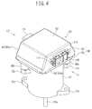
- the electronic control unit 50 includes first and second power modules 60A and 60B, an input and output board 70, a control board 80, and a housing 90 configured to accommodate them.
- the first power module 60A includes the motor current cutoff circuit 33A, a first inverter circuit 42A including plural switching elements, and a power cutoff circuit 44A.
- the second power module 60B includes, mainly, the motor current cutoff circuit 33B, a second inverter circuit 42B including plural switching elements, and a power cutoff circuit 44B.
- the input and output board 70 includes a power supply input connector (an input connector) 71 to which the power is input, a three-phase output connector (an output connector) 100 of making an output to the electric motor 12, and electronic parts (discrete parts) 73 such as electrolytic capacitors CA and CB, coils 73a and 73b included in a noise filter 43, resistors, and a three-terminal regulator 73.
- the control board 80 includes the control operation device 31 operating as a controller of controlling output currents from the first and second power modules 60A and 60B, a gate drive device 82A equipped with the gate drive circuit 41A, a gate drive device 82B equipped with the gate drive circuit 41B, and electronic parts such as capacitors, resistors, and a signal input connector 81.
- the input and output board 70 has a multilayer interconnection structure in which wiring layers are arranged on, for example, a top face 70d and a bottom face 70e, or on the top face 70d, the bottom face 70e, and an inner layer.
- the control board 80 has a multilayer interconnection structure in which wiring layers are arranged, for example, on a top face 80b and a bottom face 80c, or on the top face 80b, the bottom face 80c, and an inner layer.
- the interconnection structure extending between output terminals 66A and 66B of the first and second power modules 60A and 60B in the input and output board 70 (see FIG. 17 ) and the three-phase output connector 100 will be described later in detail.
- the housing 90 mainly includes a case 91 and a cover 95, such that the first and second power modules 60A and 60B, the input and output board 70, and the control board 80 are accommodated in an accommodation portion including the case 91 and the cover 95.
- the case 91 and the cover 95 are made of an electrically conductive material, for example, Aluminum Die Cast (ADC).
- the case 91 has a depressed shape including a ceiling 92, a side wall 93 integrally arranged at the edge of the ceiling 92 to surround the center of the ceiling 92, and an opening portion arranged on the opposite side to the ceiling 92.
- the cover 95 is attached to cover the opening portion.
- the case 91 is formed to have a substantially rectangular shape in a plane view, and includes four side walls 93 (93a, 93b, 99c, and 93d).
- the two side walls 93a and 93b face each other in a first direction (left-right direction), and the other two side walls 93c and 93d face each other in a second direction (front-rear direction) perpendicular to the first direction.
- the first and second power modules 60A and 60B are individually screwed and secured to the two side walls 93c and 93d facing each other of the case 91 with screw members 65 from the inside.
- the input and output board 70 is screwed and secured to the ceiling 92 of the case 91 with a screw member 75 from the inside.
- the control board 80 is screwed and secured to the ceiling 92 of the case 91 with screw members 85 from the inside.
- the cover 95 is screwed and secured to the side walls 93a, 93b, 93c, and 93d of the case 91 with screw members 96 from its outer side.
- the input and output board 70 and the control board 80 face each other with a predetermined space D (see FIG. 9 ) in a thickness direction of the electronic control unit 50, that is an up-down direction.
- the input and output board 70 is arranged above the control board 80 with the top being set to "up" and the bottom being set to "down”.
- the three-phase output connector 100 mounted on the input and output board 70 is exposed outwardly from the side wall 93a of the case 91 (see FIG. 4 and FIG. 5 ).
- the power supply input connector 71 of the input and output board 70 and the signal input connector 81 of the control board 80 are exposed outwardly from the side wall 93b of the case 91 (see FIG. 6 ).
- a detailed configuration of the three-phase output connector 100 will be described later.
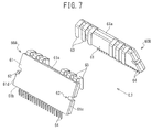
- each of the first and second power modules 60A and 60B includes a seal body 61, plural first leads 63, and plural second leads 64.
- Each of the first and second power modules 60A and 60B has a package structure of a bidirectional lead array type.
- the seal body 61 is formed to have a rectangular plane shape in a plane view, and is formed in rectangular having, for example, two long sides 61a and 61b and two short sides 61c and 61d in one embodiment of the present invention.
- the seal body 61 is made of, for example, an insulating resin or ceramics.
- the seal body 61 of the first power module 60A mainly seals the switching elements included in the first inverter circuit 42A.
- the seal body 61 of the second power module 60B mainly seals the switching elements included in the second inverter circuit 42B.
- first and second leads 63 and 64 are not illustrate in detail, but they extend over the inside and outside of the seal body 61, and includes an inner lead part located at the inside of the seal body 61 and an outer lead part located at the outside of the seal body 61.
- Each of the plural first leads 63 extends along one long side 61a of two long sides 61a and 61b of the seal body 61, at the outer lead part located at the outside of the seal body 61.
- Each of plural second leads 64 along the other one long side 61b of the two long sides 61a and 61b of the seal body 61, at the outer lead part located at the outside of the seal body 61.
- Each of the plural first and second leads 63 and 64 is formed by bending in plural steps at the outer lead part located at the outside of the seal body 61.
- Each of the outer lead parts of the plural first leads 63 is formed by bending, for example, in three steps, including a first part 63a that protrudes from one long side 61a of the seal body 61, a second part 63b that bends in a thickness direction of the seal body 61 from the first part 63a, and a third part 63c that bends to a back face side of the seal body 61 from this second part 63b.
- Each of the outer lead parts of the plural second leads 64 is formed by bending, for example, in two steps, including a first part 64a that protrudes from the other long side 61b of the seal body 61, and a second part 64b that bends to slant toward a back face side of the seal body 61 from the first part 64a.
- each of the plural first leads 63 are, for example, soldered onto the wiring of the input and output board 70 and connected electrically and mechanically.
- each of the plural second leads 64 are, for example, soldered onto the wiring of the control board 80 and connected electrically and mechanically.
- the plural first leads 63 include the first lead 63 electrically connected to a terminal of the power supply input connector 71 and the first lead 63 electrically connected to a terminal of the three-phase output connector 100, through electric wiring of the input and output board 70.
- the plural second leads 64 include the second lead 64 electrically connected to a terminal of the signal input connector 81 through electric wiring of the control board 80.
- first lead 63 electrically connected to the terminal of the three-phase output connector 100 in the first power module 60A operates as an output terminal 66A of the first power module 60A (see FIG. 17 )
- first lead 63 electrically connected to the terminal of the three-phase output connector 100 in the second power module 60B operates as an output terminal 66B of the second power module 60B (see FIG. 17 ).
- the electronic control unit 50 configured as described above is attached at an end face on the opposite side of an output shaft 12a of the electric motor 12, and is screwed and secured with a screw member, not illustrated.
- the boss portions 95b are mounted on plural first attachment flange portions 12b arranged on the electric motor 12, and in addition, the bottom face of the cover 95 is mounted on an end face on the opposite side to the output shaft 12a.
- the electronic control unit 50 is attached onto the electric motor 12. It is to be noted that plural second attachment flange portions 12c for attaching other members are provided on the output shaft 12a side of the electric motor 12.
- the first and second power modules 60A and 60B, the input and output board 70, the control board 80, the case 91, and the cover 95 are prepared.
- the electronic parts (discrete parts) 73 such as the power supply input connector 71, the three-phase output connector 100, the electrolytic capacitors CA and CB, the coils 73a and 73b included in the noise filter 43, the resistors, and the three-terminal regulator are mounted.
- the control board 80 electronic parts such as the control device (control operation device 31) that controls output currents from the first and second power modules 60A and 60B, and the gate drive device (gate drive circuits 41A and 41B) are mounted. Further, the electronic parts such as the capacitors, the resistors, and the signal input connector 81 are mounted.
- first and second power modules 60A and 60B are individually screwed and secured onto the side walls 93c and 93d of the case 91 with screw members 65 from the inside.
- the input and output board 70 is screwed and secured onto the ceiling 92 of the case 91 with the screw members 75 from the inside.
- the input and output board 70 includes plural screw through holes 70c. In screwing and securing, the screw members 75 are respectively inserted through the screw through holes 70c.
- plural first leads 63 of the first and second power modules 60A and 60B are inserted into through holes (not illustrated) arranged in the wiring of the input and output board 70.
- control board 80 is screwed and secured onto the ceiling 92 of the case 91 with the screw members 85 from the inside.
- the control board 80 includes plural screw through holes 80a. In screwing and securing, the screw members 85 are respectively inserted into the screw through holes 80a. Further, when the control board 80 is screwed and secured onto the ceiling 92 of the case 91, the plural second leads 64 of the first and second power modules 60A and 60B are inserted into through holes (not illustrated) arranged in the wiring of the control board 80.
- plural first leads 63 of the first and second power modules 60A and 60B are electrically and mechanically connected to the through holes arranged in the input and output board 70 by soldering, and at the same time, the plural second leads 64 of the first and second power modules 60A and 60B are electrically and mechanically connected to the through holes arranged in the control board 80 by soldering.
- the cover 95 is attached to cover the opening of the case 91, and is screwed and secured to the side wall 93 of the case 91 with screw members 96 from the outside of the cover 95.
- Plural screw through holes 95a are arranged in the cover 95, and in screwing and securing, the screw members 96 are respectively inserted into the through holes 95a.
- the electronic control unit 50 in one embodiment of the present invention is almost produced.
- the input and output board 70 and the control board 80 are arranged to face each other with a predetermined space D in a direction of the thickness of the electronic control unit 50, that is in the up-down direction.
- the input and output board 70 is arranged closer to the ceiling 92 of the case 91 than to the control board 80, the control board 80 is arranged closer to the cover 95 than to the input and output board 70, that is, arranged on the lower side.
- the input and output board 70 is formed to have a plane size that is smaller than the plane size of the control board 80.
- the input and output board 70 has two sides 70a and 70b facing each other, and the control board 80 has two sides 80aa and 80bb facing each other.
- One side 70a of the input and output board 70 is located on the same side with one side 80aa of the control board 80, and is located on an inner side than the one side 80aa.
- the other side 70b of the input and output board 70 is located on the same side with the other side 80bb of the control board 80, and is located on an inner side than the other side 80bb.
- the first power module 60A is arranged to intersect one side 70a of the input and output board 70 on the one sides 70a and 80aa side of the input and output board 70 and the control board 80.
- the second power module 60B is arranged to intersect one side 70b of the input and output board 70 on the other sides 70a and 80aa side of the input and output board 70 and the control board 80.
- the electronic parts 73 mounted on the input and output board 70 are discrete parts including, for example, electrolytic capacitors CA and CB, the coils 73a and 73b included in the noise filter 43, the resistors, and the three-terminal regulators.
- the electrolytic capacitors CA and CB, the coils 73a and 73b included in the noise filter 43 are relatively higher electronic parts 73.
- a height H1 of the coil 73a, a height H2 of the coil 73b, and a height H3 of the electrolytic capacitors CA and CB, which are the electronic parts 73 considered to be relatively high, as illustrated in FIG. 11 are larger than a half, which is 2/D, a distance D between the input and output board 70 and the control board (see FIG. 9 ).
- the discrete parts such as the coils 73a and 73b and the electrolytic capacitors CA and CB, which are the electronic parts 73 considered to be relatively high are mounted only on a face of the input and output board 70 facing the control board 80, that is, only on the bottom face 70e of the input and output board 70. As illustrated in FIG. 10 and FIG. 11 , the electronic parts 73 are not mounted on a top face 70d of the input and output board 70, the top face 80b of the control board 80, or the bottom face 80c of the control board 80.
- the discrete parts which are the electronic parts 73 considered to be relatively high are mounted only on a face of the input and output board 70 facing the control board 80, that is, only on the bottom face 70e of the input and output board 70. Accordingly, the height size of the electronic control unit 50 can be lowered without limiting the mounting arrangement of the input and output board 70 or the control board 80 facing each other in the up-down direction.
- the output terminal 66A of the first power module includes a first A-phase output terminal 66Aa, a first B-phase output terminal 66Ab, and a first C-phase output terminal 66Ac, respectively corresponding to the A phase, B phase, and C phase of the electric motor 12.
- the output terminal 66B of the second power module 60B includes a second A-phase output terminal 66Ba, a second B-phase output terminal 66Bb, and a second C-phase output terminal 66Bc, respectively corresponding to the A phase, B phase, and C phase of the electric motor 12.
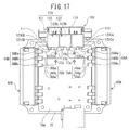
- first and second conductor patterns 7 6A and 76B are formed on the input and output board 70, as illustrated in FIG. 17 , such that the first and second conductor patterns 76A and 76B are respectively connected to the output terminals 66A and 66B of the first and second power modules 60A and 60B, and extend independently of each other.
- first and second conductor patterns 76A and 76B are arranged to be line-symmetric when viewed from a plane face of the input and output board 70.
- the first conductor pattern 76A includes a first A-phase conductor pattern 76Aa connected with and extending from the first A-phase output terminal 66Aa of the first power module 60A, a first B-phase conductor pattern 76Ab connected with and extending from the first B-phase output terminal 66Ab of the first power module 60A, and a first C-phase conductor pattern 76Ac connected with and extending from the first C-phase output terminal 66Ac of the first power module 60A.
- the first A-phase conductor pattern 76Aa extends on a top face of the input and output board 70 from the first A-phase output terminal 66Aa to a first board connection portion 121ca of the A phase terminal 121 of the three-phase output connector 100.
- first B-phase conductor pattern 76Ab extends on the top face of the input and output board 70 from the first B-phase output terminal 66Ab to a first board connection portion 122ca of the B phase terminal 122 of the three-phase output connector 100.
- the first C-phase conductor pattern 76Ac extends on the top face 70d of the input and output board 70 from the first C-phase output terminal 66Ac to the bottom face 70e of the input and output board 70 through the first through hole 77a so as not to interfere with the first B-phase conductor pattern 76Ab, extends to the second through hole 77b on the bottom face 70e of the input and output board 70, then extends to the top face 70d of the input and output board 70 through the second through hole 77b, and further extends on the top face 70d of the input and output board 70 to a first board connection portion 123ca of the C phase terminal 123 of the three-phase output connector 100.
- the second conductor pattern 76B includes, a second A-phase conductor pattern 76Ba connected with and extending from the first A-phase output terminal 66Ba of the second power module 60B, a second B-phase conductor pattern 76Bb connected with and extending from the second B-phase output terminal 66Bb of the second power module 60B, and a second C-phase conductor pattern 76Bc connected with and extending from the second C-phase output terminal 66Bc of the second power module 60B.
- the second A-phase conductor pattern 76Ba extends on the top face of the input and output board 70, from the second A-phase output terminal 66Ba to a second board connection portion 121cb of the A phase terminal 121 of the three-phase output connector 100.
- the second B--phase conductor pattern 7 6Bb extends on the top face of the input and output board 70 from the second B-phase output terminal 66Bb to a second board connection portion 122cb of the B phase terminal 122 of the three-phase output connector 100.
- the second C-phase conductor pattern 76Bc extends on the top face 70d of the input and output board 70 from the second C-phase output terminal 66Bc to the bottom face 70e of the input and output board 70 through the third through hole 77c so as not to interfere with the second B-phase conductor pattern 76Bb, extends to the fourth through hole 77d on the bottom face 70e of the input and output board 70, then extends to the top face 70d of the input and output board 70 through the fourth through hole 77d, and further extends on the top face 70d of the input and output board 70 to a second board connection portion 123cb of the C phase terminal 123 of the three-phase output connector 100.
- the three-phase output connector 100 electrically conducts an A-phase motor drive current I1a, a B-phase motor drive current I1b, and a C-phase motor drive current I1c, which are output currents from the first power module 60A, with the motor windings La, Lb, and Lc of the respective phases of the electric motor 12, and also electrically conducts an A-phase motor drive current I2a, a B-phase motor drive current I2b, and a C-phase motor drive current I1c, which are output currents from the second power module 60B, with the motor windings La, Lb, and Lc of the respective phases of the electric motor 12. Therefore, a connector (not illustrated) connected with electric wires (not illustrated) respectively connected with the motor windings La, Lb, and Lc of the respective phases of the electric motor 12 is configured to be mated with three-phase output connector 100.
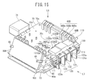
- the three-phase output connector 100 includes an insulating housing 110, and terminals 120 secured to the housing 110.
- the terminals 120 includes an A-phase terminal 121, a B-phase terminal 122, and a C-phase terminal 123, respectively corresponding to the A phase, B phase, and C phase of the electric motor 12.
- the housing 110 is molded, the A-phase terminal 121, the B-phase terminal 122, and the C-phase terminal 123 are insert-molded to be insulated from each other and overlap each other from bottom to top in an order of the A-phase terminal 121, the C-phase terminal 123, and the B-phase terminal 122 as illustrated in FIG. 11 .
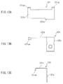
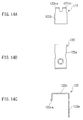
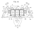
- the A-phase terminal 121 includes an output terminal portion 121a having a substantially rectangular shape extending in the up-down direction to be connected to the electric motor 12, a coupling portion 121b having a substantially rectangular shape bending from an upper end of the output terminal portion 121a and extending frontward and in a left direction, and first and second board connection portions 121ca and 121cb extending downwardly from front edges of both of left and right ends of the coupling portion 121b (edges on an opposite side to the edges from which the output terminal portion 121a extends).
- the first and second board connection portions 121ca and 121cb of the A-phase terminal 121 are arranged to be line-symmetric when viewed from a plane face of the output connector 100.
- the A-phase terminal 121 is made by stamping and bending a conductive metal plate.
- the B-phase terminal 122 includes an output terminal portion 122a having a substantially rectangular shape extending in the up-down direction to be connected to the electric motor 12, a coupling portion 122b having a substantially rectangular shape bending from an upper end of the output terminal portion 122a and extending frontward, and first and second board connection portions 122ca and 122cb extending downwardly from front edges of both of left and right ends of the coupling portion 122b.
- the B-phase terminal 122 is made by stamping and bending a conductive metal plate.
- the first and second board connection portions 122ca and 122cb are arranged to be line-symmetric when viewed from a plane face of the output connector 100, and in addition, are arranged on inner sides than the first and second board connection portions 121ca and 121cb of the A-phase terminal 121, as illustrated in FIG. 17 .
- the C-phase terminal 123 includes an output terminal portion 123a having a substantially rectangular shape extending in the up-down direction to be connected to the electric motor 12, a coupling portion 123b having a substantially rectangular shape bending from an upper end of the output terminal portion 123a and extending frontward and in a right direction, and first and second board connection portions 123ca and 123cb extending downwardly from front edges on both of left and right sides of the coupling portion 123b (edges on an opposite side to the edges from which the output terminal portion 123a extends).
- the C-phase terminal 123 is made by stamping and forming a conductive metal plate.
- the first and second board connection portions 123ca and 123cb are arranged to be line-symmetric when viewed from a plane face of the output connector 100, and in addition, arranged on inner sides than the first and second board connection portions 121ca and 121cb of the A-phase terminal 121 and on outer sides than the first and second board connection portions 122ca and 122cb of the B-phase terminal 122, as illustrated in FIG. 17 .
- the first board connection portion 121ca of the A-phase terminal 121, the first board connection portion 122ca of the B-phase terminal 122, and the first board connection portion 123ca of the C-phase terminal 123 are connected to the first conductor pattern 76A of the input and output board 70.
- the second board connection portion 121cb of the A-phase terminal 121, the second board connection portion 122cb of the B-phase terminal 122, and the second board connection portion 123cb of the C-phase terminal 123 are connected to the second conductor pattern 76B of the input and output board 70.
- the first board connection portion 121ca of the A-phase terminal 121 is connected by soldering with a first A-phase conductor pattern 76Aa
- the first board connection portion 122ca of the B-phase terminal 122 is connected by soldering with a first B-phase conductor pattern 76Ab
- the first board connection portion 123ca of the C-phase terminal 123 is connected by soldering with the first C-phase conductor pattern 76Ac.
- the second board connection portion 121cb of the A-phase terminal 121 is connected by soldering with the second A-phase conductor pattern 76Ba
- the second board connection portion 122cb of the B-phase terminal 122 is connected by soldering with the second B-phase conductor pattern 76Bb
- the second board connection portion 123cb of the C-phase terminal 123 is connected by soldering with the second C-phase conductor pattern 76Bc.
- the three-phase output connector 100 is attached to the side wall 93a of the case 91 with a pair of left and right attachment screw members 111, as illustrated in FIG. 4 .
- the first and second conductor patterns 76A and 75B are formed on the input and output board 70 to be connected with the respective output terminals 66A and 66B of the first and second power modules 60A and 60B, and then to extend independently of each other. Accordingly, the motor drive currents output from the respective output terminals 66A and 66B of the first and second power modules 60A and 60B are flowed on the input and output board 70 through the first and second conductor patterns 76A and 76B in two lines independently of each other.
- the terminals 120 (121, 122, and 123) are mounted on the output connector 100.
- the terminals 120 include the output terminal portions 121a, 122a, and 123a to be connected to the electric motor 12, and the first board connection portions 121ca, 122ca, and 123ca and the second board connection portions 121cb, 122cb, and 123cb, respectively extending from the output terminal portions 121a, 122a, and 123a and connected to the first and second conductor patterns 75A and 76B.
- the motor drive currents flow through the first and second conductor patterns 76A and 76B in two lines independently of each other, flow through the first board connection portions 121ca, 122ca, and 123ca and the second board connection portions 121cb, 122cb, and 123cb of the terminals 120 (121, 122, and 123) independently of each other, and join together at the output terminal portions 121a, 122a, and 123a to the electric motor 12, to be specific, at the coupling portions 121b, 122b, and 123b.
- the motor driver currents join together at the output terminal portions 121a, 122a, and 123a that are closest to the electric motor 12, so that distances from the output terminals 66A and 66B of the first and second power modules 60A and 60B to the electric current joining point can be made longer than the case where the electric currents are joined together on the input and output board 70.
- This configuration enables suppression of power loss from the two output terminals 66A and 66B of the first and second power modules 60A and 60B to the electric current joining point. Since the power loss is proportional to the square of the current value, a shorter distance through which the heavy-current after the electric currents are joined together flows through may be desirable.
- the motor drive current output from the first A-phase output terminal 66Aa of the first power module 60A flows through the first A-phase conductor pattern 76Aa
- the motor drive current output from the second A-phase output terminal 66Ba of the second power module 60B flows through the second A-phase conductor pattern 76Ba.
- the motor drive current that has flowed through the first A-phase conductor pattern 76Aa and the motor drive current that has flowed through the second A-phase conductor pattern 76B respectively flow across the first board connection portion 121ca and the second board connection portion 121cb of the A-phase terminal 121 independently of each other, and join together at the coupling portion 121b.
- the motor drive current output from the first B-phase output terminal 66Ab of the first power module 60A flows through the first B-phase conductor pattern 76Ab
- the motor drive current output from the second B-phase output terminal 66Bb of the second power module 60B flows through the second B-phase conductor pattern 76Bb.
- the motor drive current that has flowed through the first B-phase conductor pattern 76Ab and the motor drive current that has flowed through the second B-phase conductor pattern 76Bb respectively flow across the first board connection portion 122ca and the second board connection portion 122cb of the B-phase terminal 122 independently of each other, and join together at the coupling portion 122b.
- the motor drive current output from the first C-phase output terminal 66Ac of the first power module 60A flows through the first C-phase conductor pattern 76Ac
- the motor drive current output from the second C-phase output terminal 66Bc of the second power module 60B flows through the second C-phase conductor pattern 76Bc.
- the motor drive current that has flowed through the first C-phase conductor pattern 76Ac and the motor drive current that has flowed through the second C-phase conductor pattern 76B respectively flow across the first board connection portion 123ca and the second board connection portion 123cb of the C-phase terminal 123 independently of each other, and join together at the coupling portion 123b.
- the respective distances from output terminals 66A and 66B of the first and second power modules 60A and 60B to the joining point of the electric currents can be made longer than the case where the electric currents are joined together on the input and output board 70.
- This configuration enables the suppression of the power loss from the two output terminals 66A and 66B of the first and second power modules 60A and 60B to the joining point of the electric currents.
- the first board connection portion 121ca of the A-phase terminal 121 is connected by soldering with the first A-phase conductor pattern 76Aa and the second board connection portion 121cb of the A-phase terminal 121 is connected by soldering with the second A-phase conductor pattern 76Ba, even if one of the board connection portions is incompletely connected, the A-phase motor drive current flows, as long as the other one of the board connection portions is connected properly. Further, this phenomenon also applies to the B-phase terminal 122 and the C-phase terminal 123. Accordingly, advantages of a redundant electric join between the electronic control unit 50 and the electric motor 12 is also obtainable.
- first and second conductor patterns 7 6A and 76B are arranged to be line-symmetric when viewed from a plane face of the input and output board 70. This configuration allows a simple configuration of the input and output board 70.
- the first conductor pattern 76A includes the first A-phase conductor pattern 76Aa connected with and extending from the first A-phase output terminal 66Aa of the first power module 60A, the first B-phase conductor pattern 76Ab connected with and extending from the first B-phase output terminal 66Ab of the first power module 60A, and the first C-phase conductor pattern 76Ac connected with and extending from the first C-phase output terminal 66Ac of the first power module 60A.
- the second conductor pattern 76B includes the second A-phase conductor pattern 76Ba connected with and extending from the second A-phase output terminal 66Ba of the second power module 60B, the second B-phase conductor pattern 76Bb connected with and extending from the second B-phase output terminal 66Bb of the second power module 60B, and the second C-phase conductor pattern 76Bc connected with and extending from the second C-phase output terminal 66Bc of the second power module 60B. Accordingly, this configuration enables the wiring of the conductor patterns corresponding to the three-phase electric motor 12 of A phase, B phase, and C phase.
- the terminal 120 includes the A-phase terminal 121, the B-phase terminal 122, and the C-phase terminal 123, respectively corresponding to the A phase, B phase, and C phase of the electric motor 12.
- the A-phase terminal 121 includes the output terminal portion 121a, the first board connection portion 121ca to be connected to the first A-phase conductor pattern 76Aa, and the second board connection portion 121cb to be connected to the second A-phase conductor pattern 76Ba.
- the B-phase terminal 122 includes the output terminal portion 122a, the first board connection portion 122ca to be connected to the first B-phase conductor pattern 76Ab, and the second board connection portion 122cb to be connected to the second B-phase conductor pattern 76Bb.
- the C-phase terminal 123 includes the output terminal portion 123a, the first board connection portion 123ca to be connected to the first C-phase conductor pattern 76Ac, and the second board connection portion 123cb to be connected to the second C-phase conductor pattern 76Bc. Therefore, a terminal configuration corresponding to the three-phase electric motor 12 of the A phase, B phase, and C phase is achievable.
- first and second board connection portions 121ca and 121cb of the A-phase terminal 121, the first and second board connection portions 122ca and 122cb of the B-phase terminal 122, and the first and second board connection portions 123ca and 123cb of the C-phase terminal 123 are arranged to be line-symmetric when viewed from a plane face of the output connector 100.
- This configuration easily achieves the arrangements of the first and second conductor patterns 76A and 76B to be line-symmetric when viewed from a plane face of the input and output board 70.
- first and second conductor patterns 76A and 76B formed in the input and output board 70 may be configured such that the motor drive currents are flowed independently of each other, and are not limited to those illustrated in FIG. 17 .
- an insert molding board that eliminates the need for through-holes may be applicable to the input and output board 70.
- the arrangements and shapes of the A-phase terminal 121, the B-phase terminal 122, and the C-phase terminal 123 included in the terminal 120 can be configured such that each of the A-phase terminal 121, the B-phase terminal 122, and the C-phase terminal 123 is insulated from each other, and the output terminal portion to be connected to the electric motor 12 and the first and second board connection portions respectively connected with the first and second conductor patterns 76A and 76B extending from the output terminal portion are provided.
- the arrangements and shapes are not limited to those illustrated in FIG. 10 to FIG. 18 .
- the first and second board connection portions 121ca, 121cb, 122ca, 122cb, 123ca, and 123cb may directly extend from the output terminal portions 121a, 122a, and 123a, without extending from the coupling portions 121b, 122b, and 123b.
- the terminal 120 does not necessarily include the A-phase terminal 121, the B-phase terminal 122, or the C-phase terminal 123, and may be a single terminal.
Landscapes
- Engineering & Computer Science (AREA)
- Microelectronics & Electronic Packaging (AREA)
- Chemical & Material Sciences (AREA)
- Combustion & Propulsion (AREA)
- Transportation (AREA)
- Mechanical Engineering (AREA)
- Power Engineering (AREA)
- Physics & Mathematics (AREA)
- Thermal Sciences (AREA)
- Power Steering Mechanism (AREA)
Abstract
Description
- The present invention relates to an electronic control unit (ECU: Electronic Control Unit), an electric power steering, and a vehicle, in particular, to an electronic control unit configured to control driving of an electric motor, an electric power steering device using the same, and a vehicle in which the electric power steering is equipped.
- The electronic control unit in the electric power steering device equipped in a vehicle controls driving of the electric motor, and includes a power module equipped with switching elements, and a control board on which a control device of controlling an output current from the power module is implemented. The power module is electrically connected with the electric motor via an output connector, and the control board is electrically connected with the battery and the torque sensor of the vehicle.
- In this situation, even if an abnormality occurs at the switching element (switching means) of the power module in the ECU of driving the electric motor, there is a demand for continuing of the driving of the electric motor.
- To meet this demand, the electric power steering device of
Patent Literature 1 is conventionally proposed. - In the electric power steering device of
Patent Literature 1, multi-phase motor winding of the electric motor is duplicated, for example, and each of inverter units supplies the electric current to each of the duplicated multi-phase motor windings. That is, a first inverter unit supplies the electric current to one of the multi-phase motor windings, whereas a second inverter unit supplies the electric current to the other one of the multi-phase motor windings. - Then, when the switching means (i.e., switching element) of one of the inverter units (e.g., the first inverter unit) encounters an off failure to be non-conductive, that is an open failure, the switching means suffering from the failure is identified, the switching means other than the failed switching means is controlled, and the normal inverter unit (e.g. , the second inverter unit) is controlled other than the failed inverter unit (e.g., the first inverter unit) including the failed switching means.
- PLT 1:
JP 4998836 B - The above-described electric power steering device of
PLT 1, however, has a following drawback. - That is, PLT 1 does not disclose at all anything about the actual wiring from the first inverter unit that supplies the electric current to one of the multi-phase motor windings, or the actual wiring from the second inverter unit that supplies the electric current to the other one of the multi-phase motor windings.
- In detail,
PLT 1 does not disclose at all a pattern configuration connecting from the first and second inverter units to the electric motor in the circuit board connected with the first and second inverter units, or does not disclose the output connector configuration at all. Hence, depending on the pattern configuration or the three-phase output connector configuration, the power loss from the output units of the first and second inverter units to the electric current joining point might be increased. - Accordingly, the present invention has been made to address the above drawbacks, and has an object to provide an electronic control unit configured to control driving of an electric motor, an electric power steering device using the same, and a vehicle in which the electric power steering is equipped. In the electronic control unit, by designing the pattern configuration and the connector configuration of an input and output board to be connected with two power modules including first and second power modules on each of which switching elements are mounted, the power loss from output terminals of the first and second power modules to electric current joining points can be suppressed.
- In order to address the above drawback, according to one aspect of the present invention, there is provided an electronic control unit including: first and second power modules on which switching elements are respectively mounted; an input and output board on which an input connector and an output connector to be connected to an electric motor are mounted, and which is connected with the first and second power modules; and a control board on which a controller configured to control output currents from the first and second power modules. First and second conductor patterns respectively connected with output terminals of the first and second power modules and extending independently of each other are formed in the input and output board, and a terminal is mounted on the output connector, the terminal including: an output terminal portion to be connected to the electric motor; and first and second board connection portions extending from the output terminal portion to be respectively connected to the first and second conductor patterns.
- In addition, in the above-described electronic control unit, the first and second conductor patterns may be arranged to be line-symmetric when the first and second conductor patterns are viewed from a plane of the input and output board.
- Further, in the above-described electronic control unit, a first output terminal of the first power module may include a first A-phase output terminal, a first B-phase output terminal, and a first C-phase output terminal respectively corresponding to an A phase, a B phase, and a C phase of the electric motor, a second output terminal of the second power module may include a second A-phase output terminal, a second B-phase output terminal, and a second C-phase output terminal respectively corresponding to the A phase, the B phase, and the C phase of the electric motor, the first conductor pattern may include a first A-phase conductor pattern connected with and extending from the first A-phase output terminal of the first power module, a first B-phase conductor pattern connected with and extending from the first B-phase output terminal of the first power module, and a first C-phase conductor pattern connected with and extending from the first C-phase output terminal of the first power module, and the second conductor pattern may include a second A-phase conductor pattern connected with and extending from the second A-phase output terminal of the first power module, a second B-phase conductor pattern connected with and extending from the second B-phase output terminal of the first power module, and a second C-phase conductor pattern connected with and extending from the second C-phase output terminal of the first power module.
- Further, in the above-described electronic control unit, the terminal may include an A-phase terminal, a B-phase terminal, and a C-phase terminal respectively corresponding to the A phase, the B phase, and the C phase of the electric motor, the A-phase terminal may include the output terminal portion, the first board connection portion to be connected to the first A-phase conductor pattern, and the second board connection portion to be connected to the second A-phase conductor pattern, the B-phase terminal may include the output terminal portion, the first board connection portion to be connected to the first B-phase conductor pattern, and the second board connection portion to be connected to the second B-phase conductor pattern, and the C-phase terminal may include the output terminal portion, the first board connection portion to be connected to the first C-phase conductor pattern, and the second board connection portion to be connected to the second C-phase conductor pattern.
- Furthermore, in the above-described electronic control unit, the A-phase terminal, the B--phase terminal, and the C-phase terminal may be insert-molded to be insulated from each other and overlap each other, when a housing is formed.
- Moreover, in the above-described electronic control unit, the first and second board connection portions of the A-phase terminal, the first and second board connection portions of the B--phase terminal, and the first and second board connection portions of the C-phase terminal may be arranged to be line-symmetric when viewed from a plane of the output connector.
- In addition, according to another aspect of the present invention, there is provided an electric power steering device including any one of the above-described electronic control units.
- Further, according to yet another aspect of the present invention, there is provided a vehicle including the above-described electric power steering device.
- Furthermore, according to further another aspect of the present invention, there is provided an electronic control unit including: a power module including switching elements; an input and output board on which an input connector and an output connector to be connected to an electric motor are mounted; and a control board on which a controller configured to control output currents from the power module. The power module includes a seal body including the switching elements and having a rectangular plane, a plurality of first leads arranged along one of two sides located on opposite sides of the seal body, and a plurality of second leads arranged along the other one of the two sides of the seal body. The input and output board and the control board respectively have planes arranged to face each other at a given interval, the plurality of first leads are connected to the input and output board, the plurality of second leads are connected to the control board, the plurality of first leads include a power supply input lead to which the power is supplied from the input connector, and the plurality of second leads include a power supply output lead electrically connected with the power supply input lead in the seal body.
- In addition, in the above-described electronic control unit, the plurality of first leads may include first and second power supply input leads electrically separated from each other, operating as a power supply input leads. The plurality of second leads may include first and second power supply output leads electrically separated from each other, operating as a power supply output leads. The first power supply input lead may be electrically connected with the first power supply output lead, the second power supply input lead may be electrically connected with the second power supply output lead, a first reference potential may be supplied to the first power supply input lead, and a second reference potential, which is different from the first reference potential, may be supplied to the second power supply input lead.
- Further, in the above-described electronic control unit, the first and second power supply input leads may be electrically connected with the switching element. Moreover, in the above-described electronic control unit, the first and second power supply output leads may be electrically connected with the control device.
- In addition, according to yet another aspect of the present invention, there is provided an electric power steering device including the above-described electronic control unit.
- Further, according to yet another aspect of the present invention, there is provided a vehicle including the above-described electric power steering device.
- According to an electronic control unit, an electric power steering device, and a vehicle in one embodiment of the present invention, first and second conductor patterns are provided to be respectively connected with output terminals of first and second power modules and extend independently of each other, such that motor drive currents respectively output from the output terminals of the first and second power modules flow in two lines across the first and second conductor patterns independently of each other in the input and output board. In addition, the output connector includes a terminal including an output terminal portion to be connected to the electric motor, and first and second board connection portions extending from the output terminal portion to be connected respectively to the first and second conductor patterns. Hence, the motor drive currents flow across the first and second conductor patterns in two lines independently of each other, then flow through the first and second board connection portions of the terminal independently of each other, and join at the output terminal portion to be connected to the electric motor. Therefore, the motor drive currents join at the output terminal portions closest to the electric motor. This configuration makes longer the distances between the output terminals of the first and second power modules and the electric current joining point than the distance in a case where the electric currents are joined on the input and output board. Hence, the power loss from the first and second power modules to the electric current joining point is suppressed. Since the power loss is proportional to the square of the electric current value, a shorter distance through which such a heavy current flows after the electric currents are joined may be desirable.
-
-
FIG. 1 is a view of a basic configuration of an electric power steering device in which an electronic control unit operating as a motor controller in some embodiments of the present invention; -
FIG. 2 is a block diagram illustrating a control system of the motor controller of the electric power steering device illustrated inFIG. 1 ; -
FIG. 3 is an exploded perspective view of an inner configuration of the electric control unit operating as the motor controller; -
FIG. 4 is a perspective view of an outer configuration of the electric control unit; -
FIG. 5 is a first side view of the electric control unit when viewed from an arrow L1 direction; -
FIG. 6 is a second side view of the electric control unit when viewed from an arrow L2 direction; -
FIG. 7 is a perspective view of a power module ofFIG. 3 ; -
FIG. 8 is a view of the power module when viewed from an arrow L3 direction ofFIG. 7 ; -
FIG. 9 is a cross-sectional view schematically illustrating an outline configuration of a housing; -
FIG. 10 is a perspective view of an input and output board of the electric control unit on which a power supply input connector, a three-phase output connector, and electronic parts (i.e., discrete parts) are mounted; -
FIG. 11 is a front view of the input and output board when viewed from an arrow L4 direction ofFIG. 10 ; -
FIG. 12 is a side view of the input and output board when viewed from an arrow L5 direction ofFIG. 10 (i.e., an identical direction to the arrow L1 direction); -
FIG. 13A is a plan view of an A-phase terminal included in a terminal used for the three-phase output connector, when viewed in an arrow L6 direction ofFIG. 10 ; -
FIG. 13B is a side view of the A-phase terminal included in the terminal used for the three-phase output connector, when viewed in the arrow L5 direction ofFIG. 10 ; -
FIG. 13C is a front view of the A-phase terminal included in the terminal used for the three-phase output connector, when viewed in the arrow L4 direction ofFIG. 10 ; -
FIG. 14A is a plan view of a B-phase terminal included in the terminal used for the three-phase output connector, when viewed in the arrow L6 direction ofFIG. 10 ; -
FIG. 14B is a side view of the B-phase terminal included in the terminal used for the three-phase output connector, when viewed in the arrow L5 direction ofFIG. 10 ; -
FIG. 14C is a front view of the B-phase terminal included in the terminal used for the three-phase output connector, when viewed in the arrow L4 direction ofFIG. 10 ; -
FIG. 15A is a plan view of a C-phase terminal included in the terminal used for the three-phase output connector, when viewed in the arrow L6 direction ofFIG. 10 ; -
FIG. 15B is a side view of the C-phase terminal included in the terminal used for the three-phase output connector, when viewed in the arrow L5 direction ofFIG. 10 ; -
FIG. 15C is a front view of the C-phase terminal included in the terminal used for the three-phase output connector, when viewed in the arrow L4 direction ofFIG. 10 ; -
FIG. 16 is a perspective view of the input and output board and the control board connected by first and second power modules, and the power supply input connector, the three-phase output connector, and the electronic parts (i.e., discrete parts) illustrated inFIG. 10 are mounted on the input and output board; -
FIG. 17 is a plan view of the input and output board and the control board when viewed from an arrow L8 direction ofFIG. 16 (i.e., an identical direction to the arrow L6 direction); and -
FIG. 18 is a side view of the input and output board and the control board when viewed from an arrow L7 direction ofFIG. 16 (i.e., an identical direction to the arrow L5 direction). - Hereinafter, embodiments of the present invention will be described with reference to the accompanied drawings.
-
FIG. 1 is a view of a basic configuration of an electric power steering device in which an electronic control unit operating as a motor controller in some embodiments of the present invention. - The electric power steering device illustrated in
FIG. 1 is equipped in a vehicle like an automobile. In such an electric power steering device, a steering force exerted by a driver to asteering wheel 1 is transmitted to asteering shaft 2. The steeringshaft 2 includes aninput shaft 2a and anoutput shaft 2b. One end of theinput shaft 2a is coupled with thesteering wheel 1, whereas the other end thereof is coupled through asteering torque sensor 3 with the outer end of theoutput shaft 2b. - Then, the steering force that has been transmitted to the
output shaft 2b is transmitted via auniversal joint 4 to alower shaft 5, and is further transmitted to apinion shaft 7 via auniversal joint 6. The steering force that has been transmitted to thepinion shaft 7 is transmitted to atie rod 9 via asteering gear 8, so that turning wheels, not illustrated, are made to turn. Here, thesteering gear 8 is configured to be a rack and pinion form including apinion 8a connected with thepinion shaft 7 and arack 8b engaging with thepinion 8a, and the rotational motion that has been transmitted to thepinion 8a is converted at therack 8b into the straight motion of the vehicle widthwise direction. - The
output shaft 2b of thesteering shaft 2 is coupled with asteering assistance mechanism 10 that transmits a steering assistance force to theoutput shaft 2b. Thesteering assistance mechanism 10 includes areduction gear 11 including, for example, a worm gear mechanism connected with theoutput shaft 2b, and anelectric motor 12 operating as the electric motor including, for example, a three-phase brushless motor producing the steering assistance force and connected with thereduction gear 11. - The
steering torque sensor 3 detects steering torque exerted onto thesteering wheel 1 and then transmitted to theinput shaft 2a. Thesteering torque sensor 3, for example, converts the steering torque into a twisting angular displacement of a torsion bar (not illustrated) arranged between theinput shaft 2a and theoutput shaft 2b, and to convert the twisting angular displacement into an angle difference between an input-side rotational angle sensor (not illustrated) arranged on theinput shaft 2a side and an output side rotational angle sensor (not illustrated) arranged on theoutput shaft 2b side. - In addition, the
electric motor 12 is configured with, for example, a three-phase brushless motor, and as illustrated inFIG. 2 , motor windings La, Lb, and, Lc of A phase, B phase, and C phase of the three phases are respectively wound around slots of the stator. One ends of the motor windings La, Lb, and Lc of the respective phases are connected together to form a star connection, whereas the other ends of the motor windings La, Lb, and Lc of the respective phases are connected with amotor controller 20, so that motor drive currents Ia, Ib, and Ic are individually supplied. - The
electric motor 12, as illustrated inFIG. 2 , includes arotational position sensor 13a configured to detect the rotational position of the motor. The detection value from therotational position sensor 13a is supplied to a motor rotationalangle detection circuit 13, so that the motor rotationalangle detection circuit 13 detects a motor rotational angle θm. - In addition, a direct current is input into the
motor controller 20 from abattery 22 operating as a direct current power source. - Herein, as illustrated in
FIG. 2 , themotor controller 20 includes acontrol operation device 31 configured to operate three-phase voltage instruction values V1* and V2*, first and secondmotor drive circuits control operation device 31 are individually input, and first and second motorcurrent cutoff circuits motor drive circuits electric motor 12. - The
control operation device 31 receives a steering torque detected by thesteering torque sensor 3, a vehicle speed detected by avehicle speed sensor 21, and a motor rotational angle θm output from the motor rotationalangle detection circuit 13, a motor angular velocity, and a motor angular acceleration. In addition, thecontrol operation device 31 receives motor drive currents I1a to I1c and I2a to I2c, output fromcurrent detection circuits 39A and 39B, and supplied to the motor windings La, Lb, and Lc of the respective phases of theelectric motor 12. Then, thecontrol operation device 31 calculates the three-phase voltage instruction values V1* and V2* corresponding to the first and secondmotor drive circuits gate drive circuits motor drive circuits - Then, the
control operation device 31 includes anabnormality detection unit 31a configured to detect an open failure of the upper arms and a short-circuit failure of the lower arms of field effect transistors (FET) Q1 to Q6 operating as switching elements included in first andsecond inverter circuits electric motor 12. When theabnormality detection unit 31a does not detect an open failure or a short-circuit failure of the field effect transistors (FET) Q1 to Q6, theabnormality detection unit 31a outputs failure detection signals SAa and SAb of logical values "0" (normality) to thegate drive circuits motor drive circuits abnormality detection unit 31a detects the open failure and the short-circuit failure of the field effect transistors (FET) Q1 to Q6, theabnormality detection unit 31a outputs a failure detection signals SAa or SAb of a logical value "1" (abnormality) to thegate drive circuit motor drive circuit - Each of the first and second
motor drive circuits control operation device 31, and forms a gate signal, and includesgate drive circuits second inverter circuits gate drive circuits - Here, when the failure detection signal SAa input from the
control operation device 31 is the logical value "0" (normality), thegate drive circuit 41A is configured to output three gate signals of high level to the motorcurrent cutoff circuit 33A, and output the gate signal of high level to apower cutoff circuit 44A. In addition, when the failure detection signal SAa is the logical value "1" (abnormality), thegate drive circuit 41A is configured to output three gate signals of low level to the motorcurrent cutoff circuit 33A at the same time to cut off motor drive currents I1a to I1c, and output the gate signal of low level to thepower cutoff circuit 44A to cut off a battery current. - Similarly, when the failure detection signal SAa input from the
control operation device 31 is the logical value "0" (normality), thegate drive circuit 41B is configured to output three-gate signals of high level to the motorcurrent cutoff circuit 33B, and output the gate signal of high level to apower cutoff circuit 44B. In addition, when the failure detection signal SAa is the logical value "1" (abnormality), thegate drive circuit 41B is configured to output three gate signals of low level to the motorcurrent cutoff circuit 33B at the same time to cut off motor drive currents I2a to I2c, and output the gate signal of low level to thepower cutoff circuit 44B to cut off a battery current. - Further, each of the first and
second inverter circuits battery 22 through anoise filter 43 and thepower cutoff circuits - Then, each of the first and
second inverter circuits first inverter circuit 42A receive the gate signals output from thegate drive circuit 41A, and the motor drive current I1a of A phase, the motor drive current I1b of B phase, and the motor drive current I1c of C phase are supplied from between the FETs in each of the switching arms SAa, SAb, and SAc through the motorcurrent cutoff circuit 33A to the motor windings La, Lb, and Lc of the respective phases of theelectric motor 12. Further, the FETs Q1 to Q6 included in thesecond inverter circuit 42B receive gate signals output from thegate drive circuit 41B, and the motor drive current I2a of A phase, the motor drive current I2b of B phase, and the motor drive current I2c of C phase are electrically conductive from between the FETs in each of the switching arms SAa, SAb, and SAc through the motorcurrent cutoff circuit 33B to the motor windings La, Lb, and Lc of the respective phases of theelectric motor 12. - It is to be noted that the motor
current cutoff circuit 33A includes three FETs QA1 to QA3 for cutting off the current, and the motorcurrent cutoff circuit 33B includes three FETs QB1 to QB3 for cutting off the current. - Then, the source of the FET QA1 of the motor
current cutoff circuit 33A is connected with a connection point of transistors Q1 and Q2 of the switching arm SAa of thefirst inverter circuit 42A, and the drain of the FET QA1 is connected with the A-phase motor winding La of theelectric motor 12. Further, the source of the FET QA2 is connected with a connection point of transistors Q3 and Q4 of the switching arm SAb of thefirst inverter circuit 42A, and the drain of FET QA2 is connected with the B-phase motor winding Lb of theelectric motor 12. Furthermore, the source of the FET QA3 is connected with a connection point of transistors Q5 and Q6 of the switching arm SAc of thefirst inverter circuit 42A, and the drain of the FET QA3 is connected with the C-phase motor winding Lc of theelectric motor 12. - In addition, the source of the FET QB1 of the motor
current cutoff circuit 33B is connected with a connection point of the transistors Q1 and Q2 of the switching arm SBa of thesecond inverter circuit 42B, and the drain of the FET QB1 is connected with the A-phase motor winding La of theelectric motor 12. Further, the source of the FET QB2 is connected with a connection point of the transistors Q3 and Q4 of the switching arm SBb of thesecond inverter circuit 42B, and the drain of the FET QB2 is connected to the B-phase motor winding Lb of theelectric motor 12. Furthermore, the source of the FET QB3 is connected with a connection point of the transistors Q5 and Q6 of the switching arm SBc of thesecond inverter circuit 42B, and the drain of the FET QB3 is connected to the C-phase motor winding Lc of theelectric motor 12. - Thus, wiring from the drain of the FET QA1 of the motor
current cutoff circuit 33A and wiring from the drain of the FET QB1 of the motorcurrent cutoff circuit 33B are connected and joined with the A-phase motor winding La of theelectric motor 12. Also, wiring from the drain of FET QA2 of the motorcurrent cutoff circuit 33A and wiring from the drain of FET QB2 of the motorcurrent cutoff circuit 33B are connected and joined with the B-phase motor winding Lb of theelectric motor 12. Further, wiring from the drain of the FET QA3 of the motorcurrent cutoff circuit 33A and wiring from the drain of the FET QB3 of the motorcurrent cutoff circuit 33B are connected and joined with the C-phase motor winding Lc of theelectric motor 12. - Next, a configuration of an
electronic control unit 50 operating as themotor controller 20 will be described by usingFIG. 3 to FIG. 9 . - In
FIG. 3 to FIG. 9 , mainly, theelectronic control unit 50 includes first andsecond power modules output board 70, acontrol board 80, and ahousing 90 configured to accommodate them. - The
first power module 60A includes the motorcurrent cutoff circuit 33A, afirst inverter circuit 42A including plural switching elements, and apower cutoff circuit 44A. Thesecond power module 60B includes, mainly, the motorcurrent cutoff circuit 33B, asecond inverter circuit 42B including plural switching elements, and apower cutoff circuit 44B. - The input and
output board 70 includes a power supply input connector (an input connector) 71 to which the power is input, a three-phase output connector (an output connector) 100 of making an output to theelectric motor 12, and electronic parts (discrete parts) 73 such as electrolytic capacitors CA and CB, coils 73a and 73b included in anoise filter 43, resistors, and a three-terminal regulator 73. - The
control board 80 includes thecontrol operation device 31 operating as a controller of controlling output currents from the first andsecond power modules gate drive device 82A equipped with thegate drive circuit 41A, agate drive device 82B equipped with thegate drive circuit 41B, and electronic parts such as capacitors, resistors, and asignal input connector 81. The input andoutput board 70 has a multilayer interconnection structure in which wiring layers are arranged on, for example, atop face 70d and abottom face 70e, or on thetop face 70d, thebottom face 70e, and an inner layer. Thecontrol board 80 has a multilayer interconnection structure in which wiring layers are arranged, for example, on atop face 80b and abottom face 80c, or on thetop face 80b, thebottom face 80c, and an inner layer. The interconnection structure extending betweenoutput terminals second power modules FIG. 17 ) and the three-phase output connector 100 will be described later in detail. - The
housing 90 mainly includes acase 91 and acover 95, such that the first andsecond power modules output board 70, and thecontrol board 80 are accommodated in an accommodation portion including thecase 91 and thecover 95. Thecase 91 and thecover 95 are made of an electrically conductive material, for example, Aluminum Die Cast (ADC). - The
case 91 has a depressed shape including aceiling 92, aside wall 93 integrally arranged at the edge of theceiling 92 to surround the center of theceiling 92, and an opening portion arranged on the opposite side to theceiling 92. Thecover 95 is attached to cover the opening portion. Thecase 91 is formed to have a substantially rectangular shape in a plane view, and includes four side walls 93 (93a, 93b, 99c, and 93d). In the fourside walls side walls side walls - The first and
second power modules side walls case 91 withscrew members 65 from the inside. In addition, the input andoutput board 70 is screwed and secured to theceiling 92 of thecase 91 with a screw member 75 from the inside. Further, thecontrol board 80 is screwed and secured to theceiling 92 of thecase 91 withscrew members 85 from the inside. Furthermore, thecover 95 is screwed and secured to theside walls case 91 withscrew members 96 from its outer side. The input andoutput board 70 and thecontrol board 80 face each other with a predetermined space D (seeFIG. 9 ) in a thickness direction of theelectronic control unit 50, that is an up-down direction. InFIG. 3 , the input andoutput board 70 is arranged above thecontrol board 80 with the top being set to "up" and the bottom being set to "down". - The three-
phase output connector 100 mounted on the input andoutput board 70 is exposed outwardly from theside wall 93a of the case 91 (seeFIG. 4 andFIG. 5 ). In addition, the powersupply input connector 71 of the input andoutput board 70 and thesignal input connector 81 of thecontrol board 80 are exposed outwardly from theside wall 93b of the case 91 (seeFIG. 6 ). A detailed configuration of the three-phase output connector 100 will be described later. - As illustrated in
FIG. 7 andFIG. 8 , each of the first andsecond power modules seal body 61, plural first leads 63, and plural second leads 64. Each of the first andsecond power modules - The
seal body 61 is formed to have a rectangular plane shape in a plane view, and is formed in rectangular having, for example, twolong sides short sides seal body 61 is made of, for example, an insulating resin or ceramics. Theseal body 61 of thefirst power module 60A mainly seals the switching elements included in thefirst inverter circuit 42A. Theseal body 61 of thesecond power module 60B mainly seals the switching elements included in thesecond inverter circuit 42B. - Plural first and second leads 63 and 64 are not illustrate in detail, but they extend over the inside and outside of the
seal body 61, and includes an inner lead part located at the inside of theseal body 61 and an outer lead part located at the outside of theseal body 61. - Each of the plural first leads 63 extends along one
long side 61a of twolong sides seal body 61, at the outer lead part located at the outside of theseal body 61. Each of plural second leads 64 along the other onelong side 61b of the twolong sides seal body 61, at the outer lead part located at the outside of theseal body 61. - Each of the plural first and second leads 63 and 64 is formed by bending in plural steps at the outer lead part located at the outside of the
seal body 61. - Each of the outer lead parts of the plural first leads 63 is formed by bending, for example, in three steps, including a
first part 63a that protrudes from onelong side 61a of theseal body 61, asecond part 63b that bends in a thickness direction of theseal body 61 from thefirst part 63a, and athird part 63c that bends to a back face side of theseal body 61 from thissecond part 63b. - Each of the outer lead parts of the plural second leads 64 is formed by bending, for example, in two steps, including a
first part 64a that protrudes from the otherlong side 61b of theseal body 61, and asecond part 64b that bends to slant toward a back face side of theseal body 61 from thefirst part 64a. - In the first and
second power modules output board 70 and connected electrically and mechanically. In addition, each of the plural second leads 64 are, for example, soldered onto the wiring of thecontrol board 80 and connected electrically and mechanically. - Here, the plural first leads 63 include the
first lead 63 electrically connected to a terminal of the powersupply input connector 71 and thefirst lead 63 electrically connected to a terminal of the three-phase output connector 100, through electric wiring of the input andoutput board 70. In addition, the plural second leads 64 include thesecond lead 64 electrically connected to a terminal of thesignal input connector 81 through electric wiring of thecontrol board 80. - It is to be noted that the
first lead 63 electrically connected to the terminal of the three-phase output connector 100 in thefirst power module 60A operates as anoutput terminal 66A of thefirst power module 60A (seeFIG. 17 ), and thefirst lead 63 electrically connected to the terminal of the three-phase output connector 100 in thesecond power module 60B operates as anoutput terminal 66B of thesecond power module 60B (seeFIG. 17 ). - The
electronic control unit 50 configured as described above is attached at an end face on the opposite side of anoutput shaft 12a of theelectric motor 12, and is screwed and secured with a screw member, not illustrated. On the bottom face of thecover 95 included in theelectronic control unit 50, as illustrated inFIG. 3 to FIG. 6 ,plural boss portions 95b are formed to protrude. In attaching theelectronic control unit 50 onto theelectric motor 12, theboss portions 95b are mounted on plural firstattachment flange portions 12b arranged on theelectric motor 12, and in addition, the bottom face of thecover 95 is mounted on an end face on the opposite side to theoutput shaft 12a. Then, by screwing and securing the firstattachment flange portions 12b and theboss portions 95b with screw members, not illustrated, theelectronic control unit 50 is attached onto theelectric motor 12. It is to be noted that plural secondattachment flange portions 12c for attaching other members are provided on theoutput shaft 12a side of theelectric motor 12. - Next, a manufacturing method (assembling method) of the
electronic control unit 50 will be described with reference toFIG. 3 . - Firstly, the first and
second power modules output board 70, thecontrol board 80, thecase 91, and thecover 95 are prepared. On the input andoutput board 70, the electronic parts (discrete parts) 73 such as the powersupply input connector 71, the three-phase output connector 100, the electrolytic capacitors CA and CB, thecoils noise filter 43, the resistors, and the three-terminal regulator are mounted. On thecontrol board 80, electronic parts such as the control device (control operation device 31) that controls output currents from the first andsecond power modules gate drive circuits signal input connector 81 are mounted. - Next, the first and
second power modules side walls case 91 withscrew members 65 from the inside. - Then, the input and
output board 70 is screwed and secured onto theceiling 92 of thecase 91 with the screw members 75 from the inside. The input andoutput board 70 includes plural screw throughholes 70c. In screwing and securing, the screw members 75 are respectively inserted through the screw throughholes 70c. In addition, when the input andoutput board 70 is screwed and secured onto theceiling 92 of thecase 91, plural first leads 63 of the first andsecond power modules output board 70. - Next, the
control board 80 is screwed and secured onto theceiling 92 of thecase 91 with thescrew members 85 from the inside. Thecontrol board 80 includes plural screw throughholes 80a. In screwing and securing, thescrew members 85 are respectively inserted into the screw throughholes 80a. Further, when thecontrol board 80 is screwed and secured onto theceiling 92 of thecase 91, the plural second leads 64 of the first andsecond power modules control board 80. - Then, plural first leads 63 of the first and
second power modules output board 70 by soldering, and at the same time, the plural second leads 64 of the first andsecond power modules control board 80 by soldering. - Then, the
cover 95 is attached to cover the opening of thecase 91, and is screwed and secured to theside wall 93 of thecase 91 withscrew members 96 from the outside of thecover 95. Plural screw throughholes 95a are arranged in thecover 95, and in screwing and securing, thescrew members 96 are respectively inserted into the throughholes 95a. - Accordingly, the
electronic control unit 50 in one embodiment of the present invention is almost produced. - In the
electronic control unit 50, as illustrated inFIG. 9 , the input andoutput board 70 and thecontrol board 80 are arranged to face each other with a predetermined space D in a direction of the thickness of theelectronic control unit 50, that is in the up-down direction. In one embodiment of the present invention, the input andoutput board 70 is arranged closer to theceiling 92 of thecase 91 than to thecontrol board 80, thecontrol board 80 is arranged closer to thecover 95 than to the input andoutput board 70, that is, arranged on the lower side. - The input and
output board 70 is formed to have a plane size that is smaller than the plane size of thecontrol board 80. The input andoutput board 70 has twosides control board 80 has two sides 80aa and 80bb facing each other. - One
side 70a of the input andoutput board 70 is located on the same side with one side 80aa of thecontrol board 80, and is located on an inner side than the one side 80aa. Theother side 70b of the input andoutput board 70 is located on the same side with the other side 80bb of thecontrol board 80, and is located on an inner side than the other side 80bb. - The
first power module 60A is arranged to intersect oneside 70a of the input andoutput board 70 on the one sides 70a and 80aa side of the input andoutput board 70 and thecontrol board 80. Thesecond power module 60B is arranged to intersect oneside 70b of the input andoutput board 70 on theother sides 70a and 80aa side of the input andoutput board 70 and thecontrol board 80. - As described above, the
electronic parts 73 mounted on the input andoutput board 70 are discrete parts including, for example, electrolytic capacitors CA and CB, thecoils noise filter 43, the resistors, and the three-terminal regulators. Among these discrete parts, the electrolytic capacitors CA and CB, thecoils noise filter 43 are relatively higherelectronic parts 73. In other words, a height H1 of thecoil 73a, a height H2 of thecoil 73b, and a height H3 of the electrolytic capacitors CA and CB, which are theelectronic parts 73 considered to be relatively high, as illustrated inFIG. 11 , are larger than a half, which is 2/D, a distance D between the input andoutput board 70 and the control board (seeFIG. 9 ). - The discrete parts such as the
coils electronic parts 73 considered to be relatively high are mounted only on a face of the input andoutput board 70 facing thecontrol board 80, that is, only on thebottom face 70e of the input andoutput board 70. As illustrated inFIG. 10 andFIG. 11 , theelectronic parts 73 are not mounted on atop face 70d of the input andoutput board 70, thetop face 80b of thecontrol board 80, or thebottom face 80c of thecontrol board 80. - Thus, the discrete parts which are the
electronic parts 73 considered to be relatively high are mounted only on a face of the input andoutput board 70 facing thecontrol board 80, that is, only on thebottom face 70e of the input andoutput board 70. Accordingly, the height size of theelectronic control unit 50 can be lowered without limiting the mounting arrangement of the input andoutput board 70 or thecontrol board 80 facing each other in the up-down direction. - In other words, by mounting the discrete parts that are
electronic parts 73 considered to be relatively high on a face (thebottom face 70e) of the input andoutput board 70 facing thecontrol board 80, a space between the input andoutput board 70 and thecontrol board 80 can be utilized for the mounting of the discrete parts of theelectronic parts 73 considered to be relatively high, and the size of theelectronic control unit 50 can be lowered. Also, when the arrangements of the above-described discrete parts are divided into the face (thebottom face 70e) of the input andoutput board 70 facing thecontrol board 80 and the face (thetop face 80b) of thecontrol board 80 facing the input andoutput board 70, the height of theelectronic control unit 50 can be lowered. However, such a configuration brings an inconvenience of limiting the mounting arrangements of the input andoutput board 70 and thecontrol board 80 in order to avoid a contact between the discrete parts arranged on both of the input andoutput board 70 and thecontrol board 80. - Next, configurations of the
output terminals second power modules output board 70, wiring structures between theoutput terminals phase output connector 100, and a configuration of the three-phase output connector 100 will be described with reference toFIG. 10 to FIG. 18 . - Firstly, the
output terminal 66A of the first power module, as illustrated inFIG. 16 andFIG. 17 , includes a first A-phase output terminal 66Aa, a first B-phase output terminal 66Ab, and a first C-phase output terminal 66Ac, respectively corresponding to the A phase, B phase, and C phase of theelectric motor 12. In addition, theoutput terminal 66B of thesecond power module 60B, as illustrated inFIG. 16 andFIG. 17 , includes a second A-phase output terminal 66Ba, a second B-phase output terminal 66Bb, and a second C-phase output terminal 66Bc, respectively corresponding to the A phase, B phase, and C phase of theelectric motor 12. - Further, first and
second conductor patterns 7 6A and 76B are formed on the input andoutput board 70, as illustrated inFIG. 17 , such that the first andsecond conductor patterns output terminals second power modules - Here, the first and
second conductor patterns output board 70. - Then, the
first conductor pattern 76A includes a first A-phase conductor pattern 76Aa connected with and extending from the first A-phase output terminal 66Aa of thefirst power module 60A, a first B-phase conductor pattern 76Ab connected with and extending from the first B-phase output terminal 66Ab of thefirst power module 60A, and a first C-phase conductor pattern 76Ac connected with and extending from the first C-phase output terminal 66Ac of thefirst power module 60A. - Here, the first A-phase conductor pattern 76Aa extends on a top face of the input and
output board 70 from the first A-phase output terminal 66Aa to a first board connection portion 121ca of theA phase terminal 121 of the three-phase output connector 100. - In addition, the first B-phase conductor pattern 76Ab extends on the top face of the input and
output board 70 from the first B-phase output terminal 66Ab to a first board connection portion 122ca of theB phase terminal 122 of the three-phase output connector 100. - Further, the first C-phase conductor pattern 76Ac extends on the
top face 70d of the input andoutput board 70 from the first C-phase output terminal 66Ac to thebottom face 70e of the input andoutput board 70 through the first throughhole 77a so as not to interfere with the first B-phase conductor pattern 76Ab, extends to the second throughhole 77b on thebottom face 70e of the input andoutput board 70, then extends to thetop face 70d of the input andoutput board 70 through the second throughhole 77b, and further extends on thetop face 70d of the input andoutput board 70 to a first board connection portion 123ca of theC phase terminal 123 of the three-phase output connector 100. - In addition, the
second conductor pattern 76B includes, a second A-phase conductor pattern 76Ba connected with and extending from the first A-phase output terminal 66Ba of thesecond power module 60B, a second B-phase conductor pattern 76Bb connected with and extending from the second B-phase output terminal 66Bb of thesecond power module 60B, and a second C-phase conductor pattern 76Bc connected with and extending from the second C-phase output terminal 66Bc of thesecond power module 60B. - Here, the second A-phase conductor pattern 76Ba extends on the top face of the input and
output board 70, from the second A-phase output terminal 66Ba to a second board connection portion 121cb of theA phase terminal 121 of the three-phase output connector 100. - In addition, the second B--
phase conductor pattern 7 6Bb extends on the top face of the input andoutput board 70 from the second B-phase output terminal 66Bb to a second board connection portion 122cb of theB phase terminal 122 of the three-phase output connector 100. - Further, the second C-phase conductor pattern 76Bc extends on the
top face 70d of the input andoutput board 70 from the second C-phase output terminal 66Bc to thebottom face 70e of the input andoutput board 70 through the third throughhole 77c so as not to interfere with the second B-phase conductor pattern 76Bb, extends to the fourth throughhole 77d on thebottom face 70e of the input andoutput board 70, then extends to thetop face 70d of the input andoutput board 70 through the fourth throughhole 77d, and further extends on thetop face 70d of the input andoutput board 70 to a second board connection portion 123cb of theC phase terminal 123 of the three-phase output connector 100. - The three-
phase output connector 100 electrically conducts an A-phase motor drive current I1a, a B-phase motor drive current I1b, and a C-phase motor drive current I1c, which are output currents from thefirst power module 60A, with the motor windings La, Lb, and Lc of the respective phases of theelectric motor 12, and also electrically conducts an A-phase motor drive current I2a, a B-phase motor drive current I2b, and a C-phase motor drive current I1c, which are output currents from thesecond power module 60B, with the motor windings La, Lb, and Lc of the respective phases of theelectric motor 12. Therefore, a connector (not illustrated) connected with electric wires (not illustrated) respectively connected with the motor windings La, Lb, and Lc of the respective phases of theelectric motor 12 is configured to be mated with three-phase output connector 100. - The three-
phase output connector 100, as illustrated inFIG. 10 to FIG. 12 , andFIG. 16 to FIG. 18 , includes an insulatinghousing 110, andterminals 120 secured to thehousing 110. Theterminals 120 includes anA-phase terminal 121, a B-phase terminal 122, and a C-phase terminal 123, respectively corresponding to the A phase, B phase, and C phase of theelectric motor 12. When thehousing 110 is molded, theA-phase terminal 121, the B-phase terminal 122, and the C-phase terminal 123 are insert-molded to be insulated from each other and overlap each other from bottom to top in an order of theA-phase terminal 121, the C-phase terminal 123, and the B-phase terminal 122 as illustrated inFIG. 11 . - Here, as illustrated in
FIG. 10 ,FIG. 12 ,FIG. 13A, FIG. 13B, and FIG. 13C , theA-phase terminal 121 includes anoutput terminal portion 121a having a substantially rectangular shape extending in the up-down direction to be connected to theelectric motor 12, acoupling portion 121b having a substantially rectangular shape bending from an upper end of theoutput terminal portion 121a and extending frontward and in a left direction, and first and second board connection portions 121ca and 121cb extending downwardly from front edges of both of left and right ends of thecoupling portion 121b (edges on an opposite side to the edges from which theoutput terminal portion 121a extends). The first and second board connection portions 121ca and 121cb of theA-phase terminal 121 are arranged to be line-symmetric when viewed from a plane face of theoutput connector 100. TheA-phase terminal 121 is made by stamping and bending a conductive metal plate. - In addition, as illustrated in
FIG. 10 ,FIG. 12 ,FIG. 14A, FIG. 14B, and FIG. 14C , the B-phase terminal 122 includes anoutput terminal portion 122a having a substantially rectangular shape extending in the up-down direction to be connected to theelectric motor 12, acoupling portion 122b having a substantially rectangular shape bending from an upper end of theoutput terminal portion 122a and extending frontward, and first and second board connection portions 122ca and 122cb extending downwardly from front edges of both of left and right ends of thecoupling portion 122b. The B-phase terminal 122 is made by stamping and bending a conductive metal plate. The first and second board connection portions 122ca and 122cb are arranged to be line-symmetric when viewed from a plane face of theoutput connector 100, and in addition, are arranged on inner sides than the first and second board connection portions 121ca and 121cb of theA-phase terminal 121, as illustrated inFIG. 17 . - Further, as illustrated in
FIG. 10 ,FIG. 12 ,FIG. 15A, FIG. 15B, and FIG. 15C , the C-phase terminal 123 includes anoutput terminal portion 123a having a substantially rectangular shape extending in the up-down direction to be connected to theelectric motor 12, acoupling portion 123b having a substantially rectangular shape bending from an upper end of theoutput terminal portion 123a and extending frontward and in a right direction, and first and second board connection portions 123ca and 123cb extending downwardly from front edges on both of left and right sides of thecoupling portion 123b (edges on an opposite side to the edges from which theoutput terminal portion 123a extends). The C-phase terminal 123 is made by stamping and forming a conductive metal plate. The first and second board connection portions 123ca and 123cb are arranged to be line-symmetric when viewed from a plane face of theoutput connector 100, and in addition, arranged on inner sides than the first and second board connection portions 121ca and 121cb of theA-phase terminal 121 and on outer sides than the first and second board connection portions 122ca and 122cb of the B-phase terminal 122, as illustrated inFIG. 17 . - The first board connection portion 121ca of the
A-phase terminal 121, the first board connection portion 122ca of the B-phase terminal 122, and the first board connection portion 123ca of the C-phase terminal 123 are connected to thefirst conductor pattern 76A of the input andoutput board 70. In addition, the second board connection portion 121cb of theA-phase terminal 121, the second board connection portion 122cb of the B-phase terminal 122, and the second board connection portion 123cb of the C-phase terminal 123 are connected to thesecond conductor pattern 76B of the input andoutput board 70. - To be specific, the first board connection portion 121ca of the
A-phase terminal 121 is connected by soldering with a first A-phase conductor pattern 76Aa, the first board connection portion 122ca of the B-phase terminal 122 is connected by soldering with a first B-phase conductor pattern 76Ab, and the first board connection portion 123ca of the C-phase terminal 123 is connected by soldering with the first C-phase conductor pattern 76Ac. - Also, the second board connection portion 121cb of the
A-phase terminal 121 is connected by soldering with the second A-phase conductor pattern 76Ba, the second board connection portion 122cb of the B-phase terminal 122 is connected by soldering with the second B-phase conductor pattern 76Bb, and the second board connection portion 123cb of the C-phase terminal 123 is connected by soldering with the second C-phase conductor pattern 76Bc. - In addition, the three-
phase output connector 100 is attached to theside wall 93a of thecase 91 with a pair of left and rightattachment screw members 111, as illustrated inFIG. 4 . - In the
electronic control unit 50 having the above configuration, the first andsecond conductor patterns 76A and 75B are formed on the input andoutput board 70 to be connected with therespective output terminals second power modules respective output terminals second power modules output board 70 through the first andsecond conductor patterns output connector 100. Theterminals 120 include theoutput terminal portions electric motor 12, and the first board connection portions 121ca, 122ca, and 123ca and the second board connection portions 121cb, 122cb, and 123cb, respectively extending from theoutput terminal portions second conductor patterns 75A and 76B. Accordingly, the motor drive currents flow through the first andsecond conductor patterns output terminal portions electric motor 12, to be specific, at thecoupling portions output terminal portions electric motor 12, so that distances from theoutput terminals second power modules output board 70. This configuration enables suppression of power loss from the twooutput terminals second power modules - Specifically, the motor drive current output from the first A-phase output terminal 66Aa of the
first power module 60A flows through the first A-phase conductor pattern 76Aa, and the motor drive current output from the second A-phase output terminal 66Ba of thesecond power module 60B flows through the second A-phase conductor pattern 76Ba. Then, the motor drive current that has flowed through the first A-phase conductor pattern 76Aa and the motor drive current that has flowed through the secondA-phase conductor pattern 76B respectively flow across the first board connection portion 121ca and the second board connection portion 121cb of theA-phase terminal 121 independently of each other, and join together at thecoupling portion 121b. - Further, the motor drive current output from the first B-phase output terminal 66Ab of the
first power module 60A flows through the first B-phase conductor pattern 76Ab, and the motor drive current output from the second B-phase output terminal 66Bb of thesecond power module 60B flows through the second B-phase conductor pattern 76Bb. Then, the motor drive current that has flowed through the first B-phase conductor pattern 76Ab and the motor drive current that has flowed through the second B-phase conductor pattern 76Bb respectively flow across the first board connection portion 122ca and the second board connection portion 122cb of the B-phase terminal 122 independently of each other, and join together at thecoupling portion 122b. - Furthermore, the motor drive current output from the first C-phase output terminal 66Ac of the
first power module 60A flows through the first C-phase conductor pattern 76Ac, and the motor drive current output from the second C-phase output terminal 66Bc of thesecond power module 60B flows through the second C-phase conductor pattern 76Bc. Then, the motor drive current that has flowed through the first C-phase conductor pattern 76Ac and the motor drive current that has flowed through the second C-phase conductor pattern 76B respectively flow across the first board connection portion 123ca and the second board connection portion 123cb of the C-phase terminal 123 independently of each other, and join together at thecoupling portion 123b. - Thus, the respective distances from
output terminals second power modules output board 70. This configuration enables the suppression of the power loss from the twooutput terminals second power modules - In addition, since the first board connection portion 121ca of the
A-phase terminal 121 is connected by soldering with the first A-phase conductor pattern 76Aa and the second board connection portion 121cb of theA-phase terminal 121 is connected by soldering with the second A-phase conductor pattern 76Ba, even if one of the board connection portions is incompletely connected, the A-phase motor drive current flows, as long as the other one of the board connection portions is connected properly. Further, this phenomenon also applies to the B-phase terminal 122 and the C-phase terminal 123. Accordingly, advantages of a redundant electric join between theelectronic control unit 50 and theelectric motor 12 is also obtainable. - In addition, the first and
second conductor patterns 7 6A and 76B are arranged to be line-symmetric when viewed from a plane face of the input andoutput board 70. This configuration allows a simple configuration of the input andoutput board 70. - Further, the
first conductor pattern 76A includes the first A-phase conductor pattern 76Aa connected with and extending from the first A-phase output terminal 66Aa of thefirst power module 60A, the first B-phase conductor pattern 76Ab connected with and extending from the first B-phase output terminal 66Ab of thefirst power module 60A, and the first C-phase conductor pattern 76Ac connected with and extending from the first C-phase output terminal 66Ac of thefirst power module 60A. Also, thesecond conductor pattern 76B includes the second A-phase conductor pattern 76Ba connected with and extending from the second A-phase output terminal 66Ba of thesecond power module 60B, the second B-phase conductor pattern 76Bb connected with and extending from the second B-phase output terminal 66Bb of thesecond power module 60B, and the second C-phase conductor pattern 76Bc connected with and extending from the second C-phase output terminal 66Bc of thesecond power module 60B. Accordingly, this configuration enables the wiring of the conductor patterns corresponding to the three-phaseelectric motor 12 of A phase, B phase, and C phase. - Further, the terminal 120 includes the
A-phase terminal 121, the B-phase terminal 122, and the C-phase terminal 123, respectively corresponding to the A phase, B phase, and C phase of theelectric motor 12. TheA-phase terminal 121 includes theoutput terminal portion 121a, the first board connection portion 121ca to be connected to the first A-phase conductor pattern 76Aa, and the second board connection portion 121cb to be connected to the second A-phase conductor pattern 76Ba. The B-phase terminal 122 includes theoutput terminal portion 122a, the first board connection portion 122ca to be connected to the first B-phase conductor pattern 76Ab, and the second board connection portion 122cb to be connected to the second B-phase conductor pattern 76Bb. Furthermore, the C-phase terminal 123 includes theoutput terminal portion 123a, the first board connection portion 123ca to be connected to the first C-phase conductor pattern 76Ac, and the second board connection portion 123cb to be connected to the second C-phase conductor pattern 76Bc. Therefore, a terminal configuration corresponding to the three-phaseelectric motor 12 of the A phase, B phase, and C phase is achievable. - Moreover, the first and second board connection portions 121ca and 121cb of the
A-phase terminal 121, the first and second board connection portions 122ca and 122cb of the B-phase terminal 122, and the first and second board connection portions 123ca and 123cb of the C-phase terminal 123 are arranged to be line-symmetric when viewed from a plane face of theoutput connector 100. This configuration easily achieves the arrangements of the first andsecond conductor patterns output board 70. - The embodiments of the present invention have been described heretofore, but, the present invention is not limited to the above embodiments. Various changes and improvements are applicable.
- For example, the first and
second conductor patterns output board 70 may be configured such that the motor drive currents are flowed independently of each other, and are not limited to those illustrated inFIG. 17 . - Also, an insert molding board that eliminates the need for through-holes may be applicable to the input and
output board 70. - In addition, the arrangements and shapes of the
A-phase terminal 121, the B-phase terminal 122, and the C-phase terminal 123 included in the terminal 120 can be configured such that each of theA-phase terminal 121, the B-phase terminal 122, and the C-phase terminal 123 is insulated from each other, and the output terminal portion to be connected to theelectric motor 12 and the first and second board connection portions respectively connected with the first andsecond conductor patterns FIG. 10 to FIG. 18 . - Further, in each of the
A-phase terminal 121, the B-phase terminal 122, and the C-phase terminal 123, the first and second board connection portions 121ca, 121cb, 122ca, 122cb, 123ca, and 123cb may directly extend from theoutput terminal portions coupling portions - Furthermore, the terminal 120 does not necessarily include the
A-phase terminal 121, the B-phase terminal 122, or the C-phase terminal 123, and may be a single terminal. -
- 1 ... steering wheel, 2 ... steering shaft, 2a ... input shaft, 2b ... output shaft, 3 ... steering torque sensor, 4 ... universal joint, 5 ... lower shaft, 6 ... universal joint portion, 7 ... pinion shaft, 8 ... steering gear, 8a ... pinion, 8b ... rack, 9 ... tie rod, 10 ... steering assistance mechanism, 11 ... reduction gear, 12 ... electric motor, 12a ... output shaft, 12b ... first flange portion, 12c ... second flange portion, 13 ... motor rotational angle detection circuit, 13a ... rotational position sensor, La ... A-phase motor winding, Lb ... B-phase motor winding, Lc ... C-phase motor winding, 20 ... motor controller, 21 ... speed sensor, 22 ... battery, 31 ... control operation device, 32A ... first motor drive circuit, 32B ... second motor drive circuit, 33A ... first motor current cutoff circuit, 33B ... second motor current cutoff circuit, 39A, 39B ... current detection circuit, 41A, 41B ... gate drive circuit, 42A, 42B ... inverter circuit, 43 ... noise filter, 44A, 44B ... power cutoff circuit, 50 ... electronic control unit, 60A ... first power module, 60B ... second power module, 61 ... seal body, 61a, 61b ... long side, 61c, 61d ... short side, 63 ... first lead, 63a ... first part, 63b ... second part, 63c ... third part, 64 ... second lead, 64a ... first part, 64b ... second part, 65 ... screw member, 66A ... output terminal of the first power module, 66Aa ... first A-phase output terminal, 66Ab ... first B-phase output terminal, 66Ac ... first C-phase output terminal, 66B ... output terminal of the second power module, 66Ba ... second A-phase output terminal, 66Bb ... second B-phase output terminal, 66Bc ... second C-phase output terminal, 70 ... input and output board 70, 70c ... screw through hole, 70d ... top face of the input and output board, 70e ... bottom face of the input and output board, 71 ... power supply input connector (input connector), 73 ... electronic part (discrete part), 73a ... coil, 73b ... coil, 75 ... screw member, 76A ... first conductor pattern, 76Aa ... first A-phase conductor pattern, 76Ab ... first B-phase conductor pattern, 76Ac ... first C-phase conductor pattern, 76B ... second conductor pattern, 76Ba ... second A-phase conductor pattern, 76Bb ... second B-phase conductor pattern, 76Bc ... second C-phase conductor pattern, 77a ... first through hole, 77b ... second through hole, 77c ... third through hole, 77d ... fourth through hole, 80 ... control board, 80a ... screw through holes, 80b ... top face of the control board, 80c ... bottom face of the control board, 81 ... signal input connector, 82A ... gate drive device, 82B ... gate drive device, 83 ... opening, 85 ... screw member, 90 ... housing, 91 ... case, 92 ... ceiling, 93a, 93b, 93c, 93d ... side wall, 95 ... cover, 95a ... screw through hole, 95b ... boss portion, 96 ... screw member, 100 ... three-phase output connector (output connector), 110 ... housing, 120 ... terminal, 121 ... A-phase terminal, 121a ... output terminal portion, 121b ... coupling portion, 121ca ... first board connection portion, 121cb... second board connection portion, 122 ... B-phase terminal, 122a ... output terminal portion, 122b ... coupling portion, 122ca ... first board connection portion, 122cb ... second board connection portion, 123 ... C-phase terminal, 123a ... output terminal portion, 123b ... coupling portion, 123ca ... first board connection portion, 123cb ... second board connection portion
Claims (8)
- An electronic control unit comprising:first and second power modules on which switching elements are respectively mounted;an input and output board on which an input connector and an output connector to be connected to an electric motor are mounted, and which is connected with the first and second power modules; anda control board on which a controller configured to control output currents from the first and second power modules,wherein first and second conductor patterns respectively connected with output terminals of the first and second power modules and extending independently of each other are formed in the input and output board, and
wherein a terminal is mounted on the output connector, the terminal comprising:an output terminal portion to be connected to the electric motor; andfirst and second board connection portions extending from the output terminal portion to be respectively connected to the first and second conductor patterns. - The electronic control unit according to claim 1, wherein the first and second conductor patterns are arranged to be line-symmetric when the first and second conductor patterns are viewed from a plane of the input and output board.
- The electronic control unit according to claim 1 or claim 2,
wherein a first output terminal of the first power module comprises a first A-phase output terminal, a first B-phase output terminal, and a first C-phase output terminal respectively corresponding to an A phase, a B phase, and a C phase of the electric motor,
wherein a second output terminal of the second power module comprises a second A-phase output terminal, a second B-phase output terminal, and a second C-phase output terminal respectively corresponding to the A phase, the B phase, and the C phase of the electric motor,
wherein the first conductor pattern comprises a first A-phase conductor pattern connected with and extending from the first A-phase output terminal of the first power module, a first B-phase conductor pattern connected with and extending from the first B-phase output terminal of the first power module, and a first C-phase conductor pattern connected with and extending from the first C-phase output terminal of the first power module, and
wherein the second conductor pattern comprises a second A-phase conductor pattern connected with and extending from the second A-phase output terminal of the second power module, a second B-phase conductor pattern connected with and extending from the second B-phase output terminal of the second power module, and a second C-phase conductor pattern connected with and extending from the second C-phase output terminal of the second power module. - The electronic control unit according to claim 3,
wherein the terminal comprises an A-phase terminal, a B-phase terminal, and a C-phase terminal respectively corresponding to the A phase, the B phase, and the C phase of the electric motor,
wherein the A-phase terminal comprises the output terminal portion, the first board connection portion to be connected to the first A-phase conductor pattern, and the second board connection portion to be connected to the second A-phase conductor pattern,
wherein the B-phase terminal comprises the output terminal portion, the first board connection portion to be connected to the first B-phase conductor pattern, and the second board connection portion to be connected to the second B-phase conductor pattern, and
wherein the C-phase terminal comprises the output terminal portion, the first board connection portion to be connected to the first C-phase conductor pattern, and the second board connection portion to be connected to the second C-phase conductor pattern. - The electronic control unit according to claim 4, wherein the A-phase terminal, the B-phase terminal, and the C-phase terminal are insert-molded to be insulated from each other and overlap each other, when a housing is formed.
- The electronic control unit according to claim 4 or claim 5, wherein the first and second board connection portions of the A-phase terminal, the first and second board connection portions of the B-phase terminal, and the first and second board connection portions of the C-phase terminal are arranged to be line-symmetric when viewed from a plane of the output connector.
- An electric power steering device comprising the electronic control unit according to any one of claim 1 to claim 6.
- A vehicle comprising the electric power steering device according to claim 7.
Applications Claiming Priority (9)
| Application Number | Priority Date | Filing Date | Title |
|---|---|---|---|
| JP2013258301A JP5983591B2 (en) | 2013-12-13 | 2013-12-13 | Electronic control unit, electric power steering apparatus and vehicle |
| JP2013258300A JP5979127B2 (en) | 2013-12-13 | 2013-12-13 | Electronic control unit, electric power steering apparatus and vehicle |
| JP2013258299A JP5915635B2 (en) | 2013-12-13 | 2013-12-13 | Electronic control unit, electric power steering apparatus, vehicle, and manufacturing method of electronic control unit |
| JP2013258298A JP5900475B2 (en) | 2013-12-13 | 2013-12-13 | Electronic control unit, electric power steering apparatus and vehicle |
| JP2013263957A JP2015120367A (en) | 2013-12-20 | 2013-12-20 | Electronic control unit, electric power steering device and vehicle |
| JP2013263960A JP2015120368A (en) | 2013-12-20 | 2013-12-20 | Electronic control unit, electric power steering apparatus and vehicle |
| JP2013263958A JP5967069B2 (en) | 2013-12-20 | 2013-12-20 | Electronic control unit, electric power steering apparatus and vehicle |
| JP2013263959A JP6075282B2 (en) | 2013-12-20 | 2013-12-20 | Electronic control unit, electric power steering apparatus and vehicle |
| PCT/JP2014/006200 WO2015087554A1 (en) | 2013-12-13 | 2014-12-12 | Electronic control unit, electric power steering device, and vehicle |
Publications (3)
| Publication Number | Publication Date |
|---|---|
| EP3082232A1 true EP3082232A1 (en) | 2016-10-19 |
| EP3082232A4 EP3082232A4 (en) | 2017-10-18 |
| EP3082232B1 EP3082232B1 (en) | 2019-04-10 |
Family
ID=53370878
Family Applications (3)
| Application Number | Title | Priority Date | Filing Date |
|---|---|---|---|
| EP14870452.1A Withdrawn EP3082245A4 (en) | 2013-12-13 | 2014-12-12 | Electronic control unit, electric power steering device, and vehicle |
| EP14869940.8A Not-in-force EP3082232B1 (en) | 2013-12-13 | 2014-12-12 | Electronic control unit, electric power steering device, and vehicle |
| EP14869924.2A Not-in-force EP3081457B1 (en) | 2013-12-13 | 2014-12-12 | Electronic control unit, electric power steering device, and vehicle |
Family Applications Before (1)
| Application Number | Title | Priority Date | Filing Date |
|---|---|---|---|
| EP14870452.1A Withdrawn EP3082245A4 (en) | 2013-12-13 | 2014-12-12 | Electronic control unit, electric power steering device, and vehicle |
Family Applications After (1)
| Application Number | Title | Priority Date | Filing Date |
|---|---|---|---|
| EP14869924.2A Not-in-force EP3081457B1 (en) | 2013-12-13 | 2014-12-12 | Electronic control unit, electric power steering device, and vehicle |
Country Status (4)
| Country | Link |
|---|---|
| US (3) | US20160362127A1 (en) |
| EP (3) | EP3082245A4 (en) |
| CN (3) | CN105722743B (en) |
| WO (3) | WO2015087553A1 (en) |
Cited By (1)
| Publication number | Priority date | Publication date | Assignee | Title |
|---|---|---|---|---|
| US11014602B2 (en) | 2016-03-04 | 2021-05-25 | Nidec Corporation | Power conversion device, motor drive unit, electric power steering device, and relay module |
Families Citing this family (26)
| Publication number | Priority date | Publication date | Assignee | Title |
|---|---|---|---|---|
| JP6083428B2 (en) * | 2014-12-16 | 2017-02-22 | トヨタ自動車株式会社 | Electric power steering device for vehicle |
| EP3131198B1 (en) * | 2015-08-10 | 2022-06-08 | Goodrich Actuation Systems Limited | Control strategy of a dual lane fault tolerant permanent magnet motor to reduce drag torque under fault condition |
| JP6595269B2 (en) | 2015-09-07 | 2019-10-23 | 日立オートモティブシステムズ株式会社 | Electric drive device and electric power steering device |
| US10566879B2 (en) * | 2015-09-14 | 2020-02-18 | Renesas Electronics Corporation | Electronic device |
| CN109075735A (en) * | 2016-03-04 | 2018-12-21 | 日本电产株式会社 | Power inverter, motor drive unit and electric power steering apparatus |
| JP6680054B2 (en) * | 2016-04-06 | 2020-04-15 | 株式会社デンソー | Drive device and electric power steering device using the same |
| JP6940358B2 (en) | 2017-09-29 | 2021-09-29 | 日本電産エレシス株式会社 | Circuit board, motor drive and electric power steering |
| DE102017223631A1 (en) * | 2017-12-21 | 2019-06-27 | Robert Bosch Gmbh | Inverter for an electric machine |
| DE102018200480A1 (en) | 2018-01-12 | 2019-07-18 | Mahle International Gmbh | Control device for driving an electric motor |
| JP6907992B2 (en) * | 2018-04-10 | 2021-07-21 | 株式会社デンソー | Drive unit and drive unit |
| KR101934993B1 (en) * | 2018-07-13 | 2019-01-03 | (주)엠에스정밀 | Automatic deceleration system of construction vehicle |
| KR101934992B1 (en) * | 2018-07-13 | 2019-04-05 | (주)엠에스정밀 | Zero start system of construction vehicle |
| KR101939794B1 (en) * | 2018-07-13 | 2019-01-17 | (주)엠에스정밀 | Safety system to prevent sudden braking of construction vehicle |
| CN109068475B (en) * | 2018-09-07 | 2023-11-10 | 英迪迈智能驱动技术无锡股份有限公司 | A PCB layout structure for cylindrical motors |
| JP6608555B1 (en) * | 2019-05-17 | 2019-11-20 | 三菱電機株式会社 | DRIVE DEVICE AND ELECTRIC POWER STEERING DEVICE |
| DE102020202364A1 (en) * | 2020-02-25 | 2021-08-26 | Robert Bosch Gesellschaft mit beschränkter Haftung | Control device, in particular steering control device |
| WO2021176934A1 (en) | 2020-03-05 | 2021-09-10 | 富士電機株式会社 | Power conversion device |
| JP6955047B2 (en) * | 2020-03-31 | 2021-10-27 | 本田技研工業株式会社 | Power control unit |
| EP4146524B1 (en) * | 2020-05-08 | 2025-12-10 | Hella Gmbh & Co. Kgaa | Electronic control unit and electric power steering system |
| WO2022018784A1 (en) | 2020-07-20 | 2022-01-27 | 株式会社日立産機システム | Scroll compressor |
| WO2022102146A1 (en) * | 2020-11-10 | 2022-05-19 | 日立Astemo株式会社 | Motor drive device |
| CN113923936B (en) * | 2021-08-30 | 2023-08-25 | 国网安徽省电力有限公司枞阳县供电公司 | Power electronic module and power electronic component packaging substrate |
| KR102649976B1 (en) * | 2021-12-21 | 2024-03-22 | 현대모비스 주식회사 | Electronic control unit for redundancy of motor driven power steering of vehicle |
| KR20230169643A (en) * | 2022-06-09 | 2023-12-18 | 현대자동차주식회사 | Motor driving apparatus |
| DE102023108059A1 (en) * | 2023-03-29 | 2024-10-02 | Rapa Automotive Gmbh & Co. Kg | ELECTRONICS KIT |
| DE102024203647A1 (en) * | 2024-04-19 | 2025-10-23 | Robert Bosch Gesellschaft mit beschränkter Haftung | Electronics unit |
Family Cites Families (62)
| Publication number | Priority date | Publication date | Assignee | Title |
|---|---|---|---|---|
| JP2880878B2 (en) | 1993-06-15 | 1999-04-12 | 九州日本電気株式会社 | Vertical surface-mount resin-encapsulated semiconductor device |
| GB2295590B (en) * | 1994-11-30 | 1999-01-20 | Nsk Ltd | Electric power steering apparatus |
| JP3538944B2 (en) | 1995-03-24 | 2004-06-14 | 株式会社デンソー | Electric power steering device |
| SE517455C2 (en) * | 1999-12-15 | 2002-06-11 | Ericsson Telefon Ab L M | Power transistor module, power amplifier and method of manufacture thereof |
| JP2002119068A (en) | 2000-10-04 | 2002-04-19 | Denso Corp | Power inverter device |
| JP2002246537A (en) | 2001-02-20 | 2002-08-30 | Denso Corp | Electronic equipment |
| US20020118511A1 (en) | 2001-02-28 | 2002-08-29 | Dujari Prateek J. | Heat dissipation device |
| JP2003309384A (en) * | 2002-04-17 | 2003-10-31 | Denso Corp | Current switching circuit device and electric power steering circuit device |
| JP3716231B2 (en) | 2002-06-19 | 2005-11-16 | 三菱電機株式会社 | Electric power steering circuit device and manufacturing method thereof |
| JP2004079776A (en) | 2002-08-19 | 2004-03-11 | Yutaka Denki Seisakusho:Kk | Method for mounting printed wiring board |
| JP3692108B2 (en) | 2002-10-01 | 2005-09-07 | 三菱電機株式会社 | Motor device for electric power steering |
| JP4161074B2 (en) | 2004-02-02 | 2008-10-08 | 三菱電機株式会社 | Electric power steering device |
| JP4389616B2 (en) * | 2004-03-15 | 2009-12-24 | 日本精工株式会社 | Electric power steering device |
| US20050253233A1 (en) * | 2004-04-28 | 2005-11-17 | Takayuki Murai | Power module and electric transportation apparatus incorporating the same |
| JP4471752B2 (en) | 2004-07-06 | 2010-06-02 | 日立オートモティブシステムズ株式会社 | Electric power steering control device and electric power steering system |
| US20090120712A1 (en) * | 2005-07-11 | 2009-05-14 | Keiji Kashimoto | Electric Power Steering Device |
| KR100646404B1 (en) | 2005-10-26 | 2006-11-14 | 주식회사 만도 | Electronic control device and electric power assist steering device of automobile |
| JP2007123644A (en) * | 2005-10-31 | 2007-05-17 | Mitsubishi Electric Corp | Power semiconductor device |
| JP4396626B2 (en) | 2005-12-14 | 2010-01-13 | 株式会社デンソー | Power converter |
| JP2007167793A (en) | 2005-12-22 | 2007-07-05 | Keiji Furukawa | Deodorizing apparatus |
| US20070152503A1 (en) * | 2005-12-30 | 2007-07-05 | Kowalick Thomas M | Vehicle connector lockout apparatus and method of using same |
| KR101039200B1 (en) * | 2006-04-11 | 2011-06-03 | 닛본 세이고 가부시끼가이샤 | Electric Power Steering Device |
| WO2007119757A1 (en) * | 2006-04-11 | 2007-10-25 | Nsk Ltd. | Electric power steering device and method of assembling the same |
| JP2008004364A (en) | 2006-06-22 | 2008-01-10 | Omron Corp | Electronic device, method for manufacturing electronic device |
| JP2008066696A (en) | 2006-08-10 | 2008-03-21 | Denso Corp | Semiconductor manufacturing apparatus and semiconductor manufacturing method |
| JP2008092632A (en) * | 2006-09-29 | 2008-04-17 | Fuji Electric Holdings Co Ltd | Inverter device |
| JP5168546B2 (en) | 2007-04-16 | 2013-03-21 | 株式会社ジェイテクト | Vehicle steering system |
| JP4385058B2 (en) * | 2007-05-07 | 2009-12-16 | 三菱電機株式会社 | Electronic control unit |
| JP2009119957A (en) * | 2007-11-13 | 2009-06-04 | Mitsubishi Electric Corp | Electronic control device and method of manufacturing electronic control device |
| JP2009132174A (en) | 2007-11-28 | 2009-06-18 | Mitsubishi Electric Corp | Electric power steering device |
| EP2233382B1 (en) * | 2008-01-25 | 2013-06-12 | Mitsubishi Electric Corporation | Electric power sterring device |
| JP5250329B2 (en) | 2008-07-30 | 2013-07-31 | 日立オートモティブシステムズ株式会社 | Electric power steering control device and electric power steering device |
| JP5114350B2 (en) * | 2008-09-12 | 2013-01-09 | 株式会社日立産機システム | Inverter device |
| JP5171520B2 (en) * | 2008-09-30 | 2013-03-27 | 日立オートモティブシステムズ株式会社 | Power converter |
| JP2010105639A (en) | 2008-10-31 | 2010-05-13 | Nsk Ltd | Electric power steering device |
| JP5191925B2 (en) * | 2009-02-26 | 2013-05-08 | 積水樹脂株式会社 | Laminated circuit board with heat dissipation pattern and heat dissipation pattern forming method |
| JP2010288328A (en) | 2009-06-09 | 2010-12-24 | Mitsubishi Electric Corp | Electronic control unit |
| JP5365872B2 (en) * | 2009-06-24 | 2013-12-11 | 株式会社デンソー | Drive device |
| JP5516066B2 (en) | 2009-06-24 | 2014-06-11 | 株式会社デンソー | Drive device |
| JP4998836B2 (en) | 2009-09-30 | 2012-08-15 | 株式会社デンソー | Control device for multi-phase rotating machine and electric power steering device using the same |
| JP5241769B2 (en) | 2010-05-12 | 2013-07-17 | 三菱電機株式会社 | Electric power steering motor |
| JP5574172B2 (en) | 2010-07-14 | 2014-08-20 | 株式会社ジェイテクト | Control device |
| JP5408502B2 (en) * | 2010-09-06 | 2014-02-05 | 株式会社デンソー | Electronic control unit |
| JP5610284B2 (en) * | 2010-09-28 | 2014-10-22 | 日本電産シンポ株式会社 | Heat dissipation structure |
| JP5338804B2 (en) | 2010-12-28 | 2013-11-13 | 株式会社デンソー | DRIVE DEVICE AND ELECTRIC POWER STEERING DEVICE USING THE SAME |
| JP5722674B2 (en) | 2011-03-22 | 2015-05-27 | 日立オートモティブシステムズ株式会社 | Drive control device for electric actuator |
| JP5563513B2 (en) | 2011-04-14 | 2014-07-30 | 日立オートモティブシステムズステアリング株式会社 | Electric power steering device |
| JP5574187B2 (en) | 2011-05-11 | 2014-08-20 | 株式会社デンソー | Drive device |
| JP2013014197A (en) | 2011-07-01 | 2013-01-24 | Jtekt Corp | Electronic control device and vehicle steering apparatus |
| US9450476B2 (en) * | 2011-09-12 | 2016-09-20 | Mitsubishi Electric Corporation | Electric drive unit |
| JP2013065695A (en) | 2011-09-16 | 2013-04-11 | Omron Automotive Electronics Co Ltd | Motor control device |
| JP2013065696A (en) * | 2011-09-16 | 2013-04-11 | Omron Automotive Electronics Co Ltd | Motor controller |
| JP2013091474A (en) | 2011-10-27 | 2013-05-16 | Nsk Ltd | Electric power steering apparatus |
| JP2013103535A (en) * | 2011-11-10 | 2013-05-30 | Honda Elesys Co Ltd | Electronic control unit for electric power steering |
| JP2013103534A (en) * | 2011-11-10 | 2013-05-30 | Honda Elesys Co Ltd | Electronic control unit for electric power steering |
| EP3713053B1 (en) * | 2012-01-25 | 2022-11-23 | Mitsubishi Electric Corporation | Driving-device-integral-type rotary electric machine |
| JP5518107B2 (en) | 2012-01-25 | 2014-06-11 | 三菱電機株式会社 | Electric power steering device |
| JP5373949B1 (en) | 2012-08-24 | 2013-12-18 | 三菱電機株式会社 | Electric power steering device |
| CN202935424U (en) | 2012-11-16 | 2013-05-15 | 联创汽车电子有限公司 | Heat radiation structure of electronic control unit in electric power steering system |
| JP6117577B2 (en) * | 2013-03-15 | 2017-04-19 | 日立オートモティブシステムズ株式会社 | Electronic control unit |
| US9831482B2 (en) * | 2013-09-06 | 2017-11-28 | Johnson Controls Technology Company | Battery module lid system and method |
| JP6117661B2 (en) * | 2013-09-19 | 2017-04-19 | 日立オートモティブシステムズ株式会社 | Electronic control unit |
-
2014
- 2014-12-12 WO PCT/JP2014/006199 patent/WO2015087553A1/en not_active Ceased
- 2014-12-12 EP EP14870452.1A patent/EP3082245A4/en not_active Withdrawn
- 2014-12-12 CN CN201480061987.6A patent/CN105722743B/en not_active Expired - Fee Related
- 2014-12-12 US US15/103,035 patent/US20160362127A1/en not_active Abandoned
- 2014-12-12 EP EP14869940.8A patent/EP3082232B1/en not_active Not-in-force
- 2014-12-12 CN CN201480067602.7A patent/CN105829189B/en not_active Expired - Fee Related
- 2014-12-12 US US15/103,496 patent/US9944312B2/en not_active Expired - Fee Related
- 2014-12-12 US US15/103,116 patent/US20160355210A1/en not_active Abandoned
- 2014-12-12 WO PCT/JP2014/006201 patent/WO2015087555A1/en not_active Ceased
- 2014-12-12 WO PCT/JP2014/006200 patent/WO2015087554A1/en not_active Ceased
- 2014-12-12 EP EP14869924.2A patent/EP3081457B1/en not_active Not-in-force
- 2014-12-12 CN CN201480067831.9A patent/CN105813921B/en not_active Expired - Fee Related
Cited By (1)
| Publication number | Priority date | Publication date | Assignee | Title |
|---|---|---|---|---|
| US11014602B2 (en) | 2016-03-04 | 2021-05-25 | Nidec Corporation | Power conversion device, motor drive unit, electric power steering device, and relay module |
Also Published As
| Publication number | Publication date |
|---|---|
| CN105829189A (en) | 2016-08-03 |
| EP3081457A1 (en) | 2016-10-19 |
| CN105722743B (en) | 2018-01-30 |
| EP3081457A4 (en) | 2017-06-07 |
| EP3081457B1 (en) | 2019-04-10 |
| US9944312B2 (en) | 2018-04-17 |
| EP3082245A4 (en) | 2017-03-22 |
| US20160355210A1 (en) | 2016-12-08 |
| WO2015087554A1 (en) | 2015-06-18 |
| WO2015087555A1 (en) | 2015-06-18 |
| CN105829189B (en) | 2018-01-30 |
| WO2015087553A1 (en) | 2015-06-18 |
| US20160311462A1 (en) | 2016-10-27 |
| CN105813921B (en) | 2018-01-05 |
| EP3082232A4 (en) | 2017-10-18 |
| EP3082232B1 (en) | 2019-04-10 |
| EP3082245A1 (en) | 2016-10-19 |
| US20160362127A1 (en) | 2016-12-15 |
| CN105722743A (en) | 2016-06-29 |
| CN105813921A (en) | 2016-07-27 |
Similar Documents
| Publication | Publication Date | Title |
|---|---|---|
| EP3082232B1 (en) | Electronic control unit, electric power steering device, and vehicle | |
| JP5915635B2 (en) | Electronic control unit, electric power steering apparatus, vehicle, and manufacturing method of electronic control unit | |
| JP7094371B2 (en) | Electric power steering device | |
| US12237788B2 (en) | Rotary electric machine control apparatus | |
| JP6680054B2 (en) | Drive device and electric power steering device using the same | |
| US9991838B2 (en) | Drive control unit for motor | |
| US20130119908A1 (en) | Electronic control unit for electric power steering | |
| US20130257193A1 (en) | Drive apparatus and method for manufacturing the same | |
| JP2017189033A (en) | DRIVE DEVICE AND ELECTRIC POWER STEERING DEVICE USING THE SAME | |
| US20150274197A1 (en) | Electronic controller for electric power steering | |
| CN108137084A (en) | Integrated electric servo steering device and its manufacturing method | |
| US20220278587A1 (en) | Electronic control unit | |
| JP5967069B2 (en) | Electronic control unit, electric power steering apparatus and vehicle | |
| JP5900475B2 (en) | Electronic control unit, electric power steering apparatus and vehicle | |
| JP6075282B2 (en) | Electronic control unit, electric power steering apparatus and vehicle | |
| US8576573B2 (en) | Controller, electric power steering provided with the same, method of manufacturing bus bar, and method of manufacturing controller | |
| JP5979127B2 (en) | Electronic control unit, electric power steering apparatus and vehicle | |
| US20250142739A1 (en) | Electronic Control Unit Capable of Suppressing an Increase in Size of a Board | |
| JP2015120367A (en) | Electronic control unit, electric power steering device and vehicle | |
| JP5983591B2 (en) | Electronic control unit, electric power steering apparatus and vehicle |
Legal Events
| Date | Code | Title | Description |
|---|---|---|---|
| PUAI | Public reference made under article 153(3) epc to a published international application that has entered the european phase |
Free format text: ORIGINAL CODE: 0009012 |
|
| 17P | Request for examination filed |
Effective date: 20160613 |
|
| AK | Designated contracting states |
Kind code of ref document: A1 Designated state(s): AL AT BE BG CH CY CZ DE DK EE ES FI FR GB GR HR HU IE IS IT LI LT LU LV MC MK MT NL NO PL PT RO RS SE SI SK SM TR |
|
| AX | Request for extension of the european patent |
Extension state: BA ME |
|
| DAX | Request for extension of the european patent (deleted) | ||
| A4 | Supplementary search report drawn up and despatched |
Effective date: 20170915 |
|
| RIC1 | Information provided on ipc code assigned before grant |
Ipc: H05K 7/14 20060101ALI20170911BHEP Ipc: B62D 5/04 20060101ALI20170911BHEP Ipc: H05K 7/20 20060101ALI20170911BHEP Ipc: H02K 11/00 20160101AFI20170911BHEP |
|
| GRAP | Despatch of communication of intention to grant a patent |
Free format text: ORIGINAL CODE: EPIDOSNIGR1 |
|
| STAA | Information on the status of an ep patent application or granted ep patent |
Free format text: STATUS: GRANT OF PATENT IS INTENDED |
|
| INTG | Intention to grant announced |
Effective date: 20181026 |
|
| GRAS | Grant fee paid |
Free format text: ORIGINAL CODE: EPIDOSNIGR3 |
|
| GRAA | (expected) grant |
Free format text: ORIGINAL CODE: 0009210 |
|
| STAA | Information on the status of an ep patent application or granted ep patent |
Free format text: STATUS: THE PATENT HAS BEEN GRANTED |
|
| AK | Designated contracting states |
Kind code of ref document: B1 Designated state(s): AL AT BE BG CH CY CZ DE DK EE ES FI FR GB GR HR HU IE IS IT LI LT LU LV MC MK MT NL NO PL PT RO RS SE SI SK SM TR |
|
| REG | Reference to a national code |
Ref country code: GB Ref legal event code: FG4D |
|
| REG | Reference to a national code |
Ref country code: CH Ref legal event code: EP Ref country code: AT Ref legal event code: REF Ref document number: 1120014 Country of ref document: AT Kind code of ref document: T Effective date: 20190415 |
|
| REG | Reference to a national code |
Ref country code: IE Ref legal event code: FG4D |
|
| REG | Reference to a national code |
Ref country code: DE Ref legal event code: R096 Ref document number: 602014044678 Country of ref document: DE |
|
| REG | Reference to a national code |
Ref country code: NL Ref legal event code: MP Effective date: 20190410 |
|
| REG | Reference to a national code |
Ref country code: LT Ref legal event code: MG4D |
|
| REG | Reference to a national code |
Ref country code: AT Ref legal event code: MK05 Ref document number: 1120014 Country of ref document: AT Kind code of ref document: T Effective date: 20190410 |
|
| PG25 | Lapsed in a contracting state [announced via postgrant information from national office to epo] |
Ref country code: NL Free format text: LAPSE BECAUSE OF FAILURE TO SUBMIT A TRANSLATION OF THE DESCRIPTION OR TO PAY THE FEE WITHIN THE PRESCRIBED TIME-LIMIT Effective date: 20190410 |
|
| PG25 | Lapsed in a contracting state [announced via postgrant information from national office to epo] |
Ref country code: FI Free format text: LAPSE BECAUSE OF FAILURE TO SUBMIT A TRANSLATION OF THE DESCRIPTION OR TO PAY THE FEE WITHIN THE PRESCRIBED TIME-LIMIT Effective date: 20190410 Ref country code: PT Free format text: LAPSE BECAUSE OF FAILURE TO SUBMIT A TRANSLATION OF THE DESCRIPTION OR TO PAY THE FEE WITHIN THE PRESCRIBED TIME-LIMIT Effective date: 20190910 Ref country code: NO Free format text: LAPSE BECAUSE OF FAILURE TO SUBMIT A TRANSLATION OF THE DESCRIPTION OR TO PAY THE FEE WITHIN THE PRESCRIBED TIME-LIMIT Effective date: 20190710 Ref country code: SE Free format text: LAPSE BECAUSE OF FAILURE TO SUBMIT A TRANSLATION OF THE DESCRIPTION OR TO PAY THE FEE WITHIN THE PRESCRIBED TIME-LIMIT Effective date: 20190410 Ref country code: AL Free format text: LAPSE BECAUSE OF FAILURE TO SUBMIT A TRANSLATION OF THE DESCRIPTION OR TO PAY THE FEE WITHIN THE PRESCRIBED TIME-LIMIT Effective date: 20190410 Ref country code: ES Free format text: LAPSE BECAUSE OF FAILURE TO SUBMIT A TRANSLATION OF THE DESCRIPTION OR TO PAY THE FEE WITHIN THE PRESCRIBED TIME-LIMIT Effective date: 20190410 Ref country code: HR Free format text: LAPSE BECAUSE OF FAILURE TO SUBMIT A TRANSLATION OF THE DESCRIPTION OR TO PAY THE FEE WITHIN THE PRESCRIBED TIME-LIMIT Effective date: 20190410 Ref country code: LT Free format text: LAPSE BECAUSE OF FAILURE TO SUBMIT A TRANSLATION OF THE DESCRIPTION OR TO PAY THE FEE WITHIN THE PRESCRIBED TIME-LIMIT Effective date: 20190410 |
|
| PG25 | Lapsed in a contracting state [announced via postgrant information from national office to epo] |
Ref country code: BG Free format text: LAPSE BECAUSE OF FAILURE TO SUBMIT A TRANSLATION OF THE DESCRIPTION OR TO PAY THE FEE WITHIN THE PRESCRIBED TIME-LIMIT Effective date: 20190710 Ref country code: RS Free format text: LAPSE BECAUSE OF FAILURE TO SUBMIT A TRANSLATION OF THE DESCRIPTION OR TO PAY THE FEE WITHIN THE PRESCRIBED TIME-LIMIT Effective date: 20190410 Ref country code: LV Free format text: LAPSE BECAUSE OF FAILURE TO SUBMIT A TRANSLATION OF THE DESCRIPTION OR TO PAY THE FEE WITHIN THE PRESCRIBED TIME-LIMIT Effective date: 20190410 Ref country code: GR Free format text: LAPSE BECAUSE OF FAILURE TO SUBMIT A TRANSLATION OF THE DESCRIPTION OR TO PAY THE FEE WITHIN THE PRESCRIBED TIME-LIMIT Effective date: 20190711 Ref country code: PL Free format text: LAPSE BECAUSE OF FAILURE TO SUBMIT A TRANSLATION OF THE DESCRIPTION OR TO PAY THE FEE WITHIN THE PRESCRIBED TIME-LIMIT Effective date: 20190410 |
|
| PG25 | Lapsed in a contracting state [announced via postgrant information from national office to epo] |
Ref country code: IS Free format text: LAPSE BECAUSE OF FAILURE TO SUBMIT A TRANSLATION OF THE DESCRIPTION OR TO PAY THE FEE WITHIN THE PRESCRIBED TIME-LIMIT Effective date: 20190810 Ref country code: AT Free format text: LAPSE BECAUSE OF FAILURE TO SUBMIT A TRANSLATION OF THE DESCRIPTION OR TO PAY THE FEE WITHIN THE PRESCRIBED TIME-LIMIT Effective date: 20190410 |
|
| REG | Reference to a national code |
Ref country code: DE Ref legal event code: R097 Ref document number: 602014044678 Country of ref document: DE |
|
| PG25 | Lapsed in a contracting state [announced via postgrant information from national office to epo] |
Ref country code: RO Free format text: LAPSE BECAUSE OF FAILURE TO SUBMIT A TRANSLATION OF THE DESCRIPTION OR TO PAY THE FEE WITHIN THE PRESCRIBED TIME-LIMIT Effective date: 20190410 Ref country code: CZ Free format text: LAPSE BECAUSE OF FAILURE TO SUBMIT A TRANSLATION OF THE DESCRIPTION OR TO PAY THE FEE WITHIN THE PRESCRIBED TIME-LIMIT Effective date: 20190410 Ref country code: SK Free format text: LAPSE BECAUSE OF FAILURE TO SUBMIT A TRANSLATION OF THE DESCRIPTION OR TO PAY THE FEE WITHIN THE PRESCRIBED TIME-LIMIT Effective date: 20190410 Ref country code: EE Free format text: LAPSE BECAUSE OF FAILURE TO SUBMIT A TRANSLATION OF THE DESCRIPTION OR TO PAY THE FEE WITHIN THE PRESCRIBED TIME-LIMIT Effective date: 20190410 Ref country code: DK Free format text: LAPSE BECAUSE OF FAILURE TO SUBMIT A TRANSLATION OF THE DESCRIPTION OR TO PAY THE FEE WITHIN THE PRESCRIBED TIME-LIMIT Effective date: 20190410 |
|
| PGFP | Annual fee paid to national office [announced via postgrant information from national office to epo] |
Ref country code: DE Payment date: 20191126 Year of fee payment: 6 |
|
| PLBE | No opposition filed within time limit |
Free format text: ORIGINAL CODE: 0009261 |
|
| STAA | Information on the status of an ep patent application or granted ep patent |
Free format text: STATUS: NO OPPOSITION FILED WITHIN TIME LIMIT |
|
| PG25 | Lapsed in a contracting state [announced via postgrant information from national office to epo] |
Ref country code: IT Free format text: LAPSE BECAUSE OF FAILURE TO SUBMIT A TRANSLATION OF THE DESCRIPTION OR TO PAY THE FEE WITHIN THE PRESCRIBED TIME-LIMIT Effective date: 20190410 Ref country code: SM Free format text: LAPSE BECAUSE OF FAILURE TO SUBMIT A TRANSLATION OF THE DESCRIPTION OR TO PAY THE FEE WITHIN THE PRESCRIBED TIME-LIMIT Effective date: 20190410 |
|
| PGFP | Annual fee paid to national office [announced via postgrant information from national office to epo] |
Ref country code: FR Payment date: 20191115 Year of fee payment: 6 |
|
| 26N | No opposition filed |
Effective date: 20200113 |
|
| PG25 | Lapsed in a contracting state [announced via postgrant information from national office to epo] |
Ref country code: TR Free format text: LAPSE BECAUSE OF FAILURE TO SUBMIT A TRANSLATION OF THE DESCRIPTION OR TO PAY THE FEE WITHIN THE PRESCRIBED TIME-LIMIT Effective date: 20190410 |
|
| PGFP | Annual fee paid to national office [announced via postgrant information from national office to epo] |
Ref country code: GB Payment date: 20191213 Year of fee payment: 6 |
|
| PG25 | Lapsed in a contracting state [announced via postgrant information from national office to epo] |
Ref country code: SI Free format text: LAPSE BECAUSE OF FAILURE TO SUBMIT A TRANSLATION OF THE DESCRIPTION OR TO PAY THE FEE WITHIN THE PRESCRIBED TIME-LIMIT Effective date: 20190410 |
|
| REG | Reference to a national code |
Ref country code: CH Ref legal event code: PL |
|
| REG | Reference to a national code |
Ref country code: BE Ref legal event code: MM Effective date: 20191231 |
|
| PG25 | Lapsed in a contracting state [announced via postgrant information from national office to epo] |
Ref country code: MC Free format text: LAPSE BECAUSE OF FAILURE TO SUBMIT A TRANSLATION OF THE DESCRIPTION OR TO PAY THE FEE WITHIN THE PRESCRIBED TIME-LIMIT Effective date: 20190410 |
|
| PG25 | Lapsed in a contracting state [announced via postgrant information from national office to epo] |
Ref country code: IE Free format text: LAPSE BECAUSE OF NON-PAYMENT OF DUE FEES Effective date: 20191212 Ref country code: LU Free format text: LAPSE BECAUSE OF NON-PAYMENT OF DUE FEES Effective date: 20191212 |
|
| PG25 | Lapsed in a contracting state [announced via postgrant information from national office to epo] |
Ref country code: BE Free format text: LAPSE BECAUSE OF NON-PAYMENT OF DUE FEES Effective date: 20191231 Ref country code: LI Free format text: LAPSE BECAUSE OF NON-PAYMENT OF DUE FEES Effective date: 20191231 Ref country code: CH Free format text: LAPSE BECAUSE OF NON-PAYMENT OF DUE FEES Effective date: 20191231 |
|
| PG25 | Lapsed in a contracting state [announced via postgrant information from national office to epo] |
Ref country code: CY Free format text: LAPSE BECAUSE OF FAILURE TO SUBMIT A TRANSLATION OF THE DESCRIPTION OR TO PAY THE FEE WITHIN THE PRESCRIBED TIME-LIMIT Effective date: 20190410 |
|
| REG | Reference to a national code |
Ref country code: DE Ref legal event code: R119 Ref document number: 602014044678 Country of ref document: DE |
|
| PG25 | Lapsed in a contracting state [announced via postgrant information from national office to epo] |
Ref country code: MT Free format text: LAPSE BECAUSE OF FAILURE TO SUBMIT A TRANSLATION OF THE DESCRIPTION OR TO PAY THE FEE WITHIN THE PRESCRIBED TIME-LIMIT Effective date: 20190410 Ref country code: HU Free format text: LAPSE BECAUSE OF FAILURE TO SUBMIT A TRANSLATION OF THE DESCRIPTION OR TO PAY THE FEE WITHIN THE PRESCRIBED TIME-LIMIT; INVALID AB INITIO Effective date: 20141212 |
|
| GBPC | Gb: european patent ceased through non-payment of renewal fee |
Effective date: 20201212 |
|
| PG25 | Lapsed in a contracting state [announced via postgrant information from national office to epo] |
Ref country code: FR Free format text: LAPSE BECAUSE OF NON-PAYMENT OF DUE FEES Effective date: 20201231 |
|
| PG25 | Lapsed in a contracting state [announced via postgrant information from national office to epo] |
Ref country code: DE Free format text: LAPSE BECAUSE OF NON-PAYMENT OF DUE FEES Effective date: 20210701 Ref country code: GB Free format text: LAPSE BECAUSE OF NON-PAYMENT OF DUE FEES Effective date: 20201212 |
|
| PG25 | Lapsed in a contracting state [announced via postgrant information from national office to epo] |
Ref country code: MK Free format text: LAPSE BECAUSE OF FAILURE TO SUBMIT A TRANSLATION OF THE DESCRIPTION OR TO PAY THE FEE WITHIN THE PRESCRIBED TIME-LIMIT Effective date: 20190410 |