EP3082231A1 - Motor - Google Patents
Motor Download PDFInfo
- Publication number
- EP3082231A1 EP3082231A1 EP14869850.9A EP14869850A EP3082231A1 EP 3082231 A1 EP3082231 A1 EP 3082231A1 EP 14869850 A EP14869850 A EP 14869850A EP 3082231 A1 EP3082231 A1 EP 3082231A1
- Authority
- EP
- European Patent Office
- Prior art keywords
- terminal
- connector
- support part
- terminal support
- radial direction
- Prior art date
- Legal status (The legal status is an assumption and is not a legal conclusion. Google has not performed a legal analysis and makes no representation as to the accuracy of the status listed.)
- Granted
Links
Images





Classifications
-
- H—ELECTRICITY
- H02—GENERATION; CONVERSION OR DISTRIBUTION OF ELECTRIC POWER
- H02K—DYNAMO-ELECTRIC MACHINES
- H02K7/00—Arrangements for handling mechanical energy structurally associated with dynamo-electric machines, e.g. structural association with mechanical driving motors or auxiliary dynamo-electric machines
- H02K7/14—Structural association with mechanical loads, e.g. with hand-held machine tools or fans
-
- H—ELECTRICITY
- H02—GENERATION; CONVERSION OR DISTRIBUTION OF ELECTRIC POWER
- H02K—DYNAMO-ELECTRIC MACHINES
- H02K3/00—Details of windings
- H02K3/46—Fastening of windings on the stator or rotor structure
- H02K3/52—Fastening salient pole windings or connections thereto
- H02K3/521—Fastening salient pole windings or connections thereto applicable to stators only
- H02K3/525—Annular coils, e.g. for cores of the claw-pole type
-
- H—ELECTRICITY
- H02—GENERATION; CONVERSION OR DISTRIBUTION OF ELECTRIC POWER
- H02K—DYNAMO-ELECTRIC MACHINES
- H02K5/00—Casings; Enclosures; Supports
- H02K5/04—Casings or enclosures characterised by the shape, form or construction thereof
- H02K5/12—Casings or enclosures characterised by the shape, form or construction thereof specially adapted for operating in liquid or gas
- H02K5/128—Casings or enclosures characterised by the shape, form or construction thereof specially adapted for operating in liquid or gas using air-gap sleeves or air-gap discs
-
- H—ELECTRICITY
- H02—GENERATION; CONVERSION OR DISTRIBUTION OF ELECTRIC POWER
- H02K—DYNAMO-ELECTRIC MACHINES
- H02K5/00—Casings; Enclosures; Supports
- H02K5/04—Casings or enclosures characterised by the shape, form or construction thereof
- H02K5/22—Auxiliary parts of casings not covered by groups H02K5/06-H02K5/20, e.g. shaped to form connection boxes or terminal boxes
- H02K5/225—Terminal boxes or connection arrangements
-
- H—ELECTRICITY
- H02—GENERATION; CONVERSION OR DISTRIBUTION OF ELECTRIC POWER
- H02K—DYNAMO-ELECTRIC MACHINES
- H02K2213/00—Specific aspects, not otherwise provided for and not covered by codes H02K2201/00 - H02K2211/00
- H02K2213/03—Machines characterised by numerical values, ranges, mathematical expressions or similar information
Definitions
- the present invention relates to a motor.
- Patent Literature 1 A stator structure of a motor is disclosed in Patent Literature 1.
- Patent Literature 1 Japanese Patent Laid-Open No. 2007-282479
- a cover made of resin for accommodating a stator assembly is adopted.
- the cover is provided with a surrounding wall part which surrounds an outer periphery of the stator assembly.
- the surrounding wall part is integrally formed with a connector cover made of resin which covers a connector.
- An inner side of the cover and an inner side of the connector cover are communicated with each other through an opening part provided in the surrounding wall part.
- a plurality of coil terminals extended in a radial direction from the stator assembly is connected with corresponding connector terminals on an inner side of the connector cover through a flexible circuit board.
- a support member made of resin which supports the connector terminals is disposed on an inner side of the connector cover.
- a connected part of the circuit board with the connector terminals is connected with the connector terminals by soldering in a contacted state with the support member.
- the support member may be melted due to heat applied when soldering is performed depending on material of the support member and, in this case, support strength for the connector terminals is lowered in the support member.
- the present invention provides a motor, in which a coil terminal extended from a stator surrounding a rotor is connected with a connector terminal supported by a terminal support part made of resin through a wiring member in a plate shape having flexibility and, in a connected part of the connector terminal with the wiring member, the connector terminal protruded from the terminal support part penetrates through the wiring member contacted with the terminal support part and is connected by soldering with a face of the wiring member on an opposite side to the terminal support part and, in the motor, a heat insulation member having an insulation property is provided between the terminal support part and the wiring member.
- the heat insulation member having an insulation property is provided between the terminal support part and the wiring member and thus influence of soldering heat when the connector terminal and the wiring member are to be connected with each other can be preferably prevented from being applied to the terminal support part.
- valve drive device (gear unit) of a valve device structured to open and close a flow passage of refrigerant in a refrigerator.
- a positional relationship of respective structural elements of a valve drive device will be appropriately described in which, with an axial line X of a rotation axis of a rotor 30 of the valve drive device 1 shown in Fig. 1 as a reference, the rotor 30 side in an axial direction of the axial line X is referred to as an upper side and a fluid lead-out pipes 3 and 4 side is referred to as a lower side.
- Fig. 1 is a cross-sectional view showing a valve drive device 1 in accordance with an embodiment of the present invention.
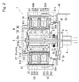
- Fig. 2 is the X1-X1 cross-sectional view in Fig. 1 .
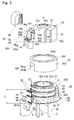
- Fig. 3 is an exploded perspective view showing a motor M side of the valve drive device 1.
- a portion formed of resin in a stator assembly 40 is indicated by hatching.
- a valve drive device 1 in accordance with an embodiment of the present invention is a valve device which structures a flow passage where fluid (in this embodiment, refrigerant) can be circulated through a refrigerator (not shown) that is an external apparatus and is structured to lead out the fluid introduced to an inside of a fluid chamber S from the refrigerator through a fluid lead-in pipe 2 to the refrigerator through fluid lead-out pipes 3 and 4.
- fluid in this embodiment, refrigerant
- valve drive device 1 a valve part 70 is driven by a motor M and fluid introduced to the fluid chamber S is led out to the refrigerator side through the fluid lead-out pipes 3 and 4.
- a claw-pole type stepping motor is adopted as a motor M of the valve drive device 1 in which a pair of stator assemblies 50A and 50B (a coil of an A-phase and a coil of a B-phase) is adjacently disposed in the axial line X direction of the rotation axis of the rotor 30.
- a fluid chamber S is formed between a bottom plate part 10 and a partition 20 by using the partition 20 in a bottomed cylindrical shape which is fixed to an upper face (rotor 30 side face) of the bottom plate part 10.
- the partition 20 is provided so that its bottom part 20a is located at an upper side (rotor 30 side) which is an opposite side to the bottom plate part 10.
- the partition 20 has an outward form which is enlarged in two steps in a direction separated from the bottom part 20a and is structured of a small diameter part 201 on the bottom part 20a side and a large diameter part 202 on the bottom plate part 10 side.
- An outer circumferential edge of the bottom plate part 10 is formed with a step part 11 over its entire periphery to which a tip end 202a of the large diameter part 202 is fitted from an outer side.
- the partition 20 is fixed to the bottom plate part 10 in a state that the tip end 202a of the large diameter part 202 is fitted to the step part 11.
- valve drive device 1 is used in an arrangement state that a rotor 30 of the motor M is disposed on an upper side and the fluid chamber S is disposed on a lower side (see Fig. 1 ).
- the rotor 30 of the motor M is provided on an inner side of the small diameter part 201 in a state externally fitted on the shaft member 21.
- the shaft member 21 in the valve drive device 1 is provided along the axial line X of the rotation axis of the rotor 30.
- One end 21a of the shaft member 21 is supported by a recessed part 20b of the bottom part 20a and the other end 21b is brazed to a hole part 10a of the bottom plate part 10.
- the shaft member 21 is provided in a rotation prevented state.
- the rotor 30 is rotatably supported by the shaft member 21 and, when the motor M is driven, the rotor 30 is rotated around the axial line X.
- the rotor 30 is structured of a base part 31 having a bearing part 31a which is externally fitted on the shaft member 21 and a magnet 32 on which an N-phase and an S-phase are alternately disposed in a circumferential direction around the axial line X.
- the magnet 32 is integrally formed with the base part 31 by insert molding when the rotor 30 is molded with resin.
- the magnet 32 is provided over the entire periphery in the circumferential direction around the axial line X to the base part 31.
- a transmission shaft 33 which transmits rotation of the rotor 30 to a valve part 70 described below is inserted between the bearing part 31a and the base part 31 and is fixed to a lower part on the bottom plate part 10 side of the base part 31.
- the transmission shaft 33 is, similarly to the rotor 30, rotatably supported by the shaft member 21 and is rotated together with the rotor 30 around the axial line X.
- the transmission shaft 33 is extended to a lower side on the bottom plate part 10 side along the axial line X and its tip end part 33a is abutted with an upper face 10b of the bottom plate part 10.
- the rotor 30 is urged to a lower side on the bottom plate part 10 side by a spring Sp which is externally fitted to one end 21a side of the shaft member 21.
- the tip end part 33a of the transmission shaft 33 is always abutted with the upper face 10b of the bottom plate part 10 by an urging force of the spring Sp to position it in the axial direction of the axial line X of the rotor 30.
- a large diameter part 33b whose diameter is larger than its tip end part 33a is provided to an upper side (rotor 30 side) of the tip end part 33a of the transmission shaft 33.
- An outer periphery of the large diameter part 33b is provided with a teeth part 33c which is engaged with a teeth part 71g provided on an outer periphery of a gear 71 described below (see Fig. 2 ).
- the small diameter part 201 of the partition 20 which accommodates the rotor 30 is formed in a tube shape surrounding the magnet 32 of the rotor 30 with a predetermined space therebetween.
- a stator assembly 40 is externally fitted and attached to an outer periphery of the small diameter part 201.
- a circular plate part 203 connecting the small diameter part 201 with the large diameter part 202 is provided so as to be perpendicular to the axial line X.
- the stator assembly 40 externally fitted to the small diameter part 201 is positioned by the circular plate part 203 and two stator assemblies 50A and 50B are disposed to an outer side in a radial direction of the rotor 30 (magnet 32).
- the magnet 32 of the rotor 30 is driven by magnetic force from the stator assembly 40 described below through the partition 20 and thus the partition 20 is structured of non-magnetic material. Further, the partition 20 is structured of metal so as to withstand pressure in the fluid chamber S. Therefore, the partition 20 is structured of stainless steel which is nonmagnetic metal.
- the stator assembly 40 includes two stator assemblies 50A and 50B which are disposed so as to be superposed on each other in the axial direction of the axial line X.
- An outer stator core 59 which surrounds outer peripheries of the stator assemblies 50A and 50B is externally fitted and attached in the stator assembly 40.
- the outer stator core 59 is, similarly to inner stator cores 51 and 52 described below, formed of a plate body of a magnetic body by press working.
- the outer stator core 59 and the inner stator cores 51 and 52 are provided in a contacted state with each other to structure magnetic paths by the outer stator core 59 and the inner stator cores 51 and 52.
- Each of the stator assemblies 50A and 50B is basically structured so that a drive coil 54 wound around an outer periphery of a bobbin 53 is disposed between a pair of inner stator cores 51 and 52 disposed with a space therebetween in the axial direction.
- the bobbin 53 is a resin molded body (insulator) in which the inner stator cores 51 and 52 of the stator assemblies 50A and 50B are embedded in its inside by insert molding and is integrally formed with a terminal holding part 55 described below.
- Fig. 4(a) is an enlarged cross-sectional view showing a main part in Fig. 1 and Fig. 4(b) is an enlarged view showing an area A in Fig. 4(a) .
- the inner stator cores 51 and 52 are provided with ring-shaped flange parts 510 and 520 disposed in a posture perpendicular to the axial line X and a plurality of pole teeth 511 and 521 which are formed so as to be stood up in the axial line X direction from inner peripheries of the flange parts 510 and 520.
- the pole teeth 511 and 521 are provided on inner diameter sides of the flange parts 510 and 520 at equal intervals in the circumferential direction around the axial line X.
- a pair of the inner stator cores 51 and 52 of the stator assemblies 50A and 50B is disposed in a posture that respective pole teeth 511 and 521 are faced each other so that the pole teeth 511 of one inner stator core 51 and the pole teeth 521 of the other inner stator core 52 are alternately and adjacently disposed to each other in the circumferential direction around the axial line X.
- a base part 530 in a cylindrical shape of the bobbin 53 whose outer periphery is wound with a coil is located on an outer side in a radial direction of the pole teeth 511 and 521.
- Flange parts 531 and 532 extended to an outer side in the radial direction are provided at both ends of the base part 530 in the axial direction of the axial line X over the entire periphery in the circumferential direction around the axial line X.
- the inner stator core 51 of the stator assembly 50A and the inner stator core 52 of the stator assembly 50B are provided in a state that the flange parts 510 and 520 (see Fig. 4 ) are contacted with each other in the axial direction of the axial line X.
- the flange parts 510 and 520 are held in the resin in a state that the flange parts 510 and 520 are contacted with each other without a gap space.
- pole teeth 511 and 521 are exposed on an inner diameter side of the base part 530 of the bobbin 53. Faces on the drive coil 54 side of the flange parts 510 and 520 are covered with resin structuring the flange parts 531 and 532.
- a ring-shaped attaching part 57 (see Figs. 2 and 3 ) is formed by using resin material covering an upper face on an inner diameter side of the flange part 510 of the stator assembly 50B.
- a fitting wall 91c of an upper cover member 90 described below is internally fitted and attached to the attaching part 57.
- a ring-shaped abutting part 58 (see Fig. 2 ) is formed by using resin material covering an under face on an inner diameter side of the flange part 520 of the stator assembly 50A.
- the abutting part 58 is abutted with the circular plate part 203 at a boundary between the small diameter part 201 and the large diameter part 202 when the stator assembly 40 is externally fitted to the small diameter part 201 of the partition 20 in the axial line X direction. Therefore, positioning in the axial direction of the stator assembly 40 is performed by the abutting part 58 which is abutted with the circular plate part 203.
- the flange parts 510 and 520 of the respective stator cores are formed with cut-out parts 510b and 520b which are recessed to the axial line X side at parts of their outer peripheral parts.
- the cut-out parts 510b and 520b of the respective flange parts 510 and 520 are provided at a position overlapped with each other viewed in the axial direction of the axial line X.
- a terminal holding part 55 is provided by utilizing the portions of the cut-out parts 510b and 520b.
- the terminal holding part 55B of the stator assembly 50B is provided so as to straddle over the cut-out parts 510b and 520b of the flange parts 510 and 520.
- the terminal holding part 55B is integrally formed with the flange parts 532 and 531 of the bobbin 53 which are located on both sides of the flange parts 510 and 520 and has a predetermined thickness in the axial direction of the axial line X.
- a terminal holding part 55A of the stator assembly 50A is provided in the cut-out part 520b of the flange part 520 of the inner stator core 52.
- the terminal holding part 55A is integrally formed with the flange part 532 of the bobbin 53 of the stator assembly 50A and has a predetermined thickness in the axial direction of the axial line X.
- the terminal holding part 55A of the stator assembly 50A and the terminal holding part 55B of the stator assembly 50B are provided with a space therebetween in the axial line X direction.
- a plurality of coil terminals 56 is press-fitted and supported by the terminal holding parts 55A and 55B of the stator assemblies 50A and 50B.
- a plurality of the coil terminals 56 is provided so as to be protruded to an outer side in the radial direction from the stator assembly 40 and base ends of the coil terminals 56 are located in the cut-out parts 510b and 520b.
- the outer stator core 59 which is externally fitted and attached to the stator assembly 40 is provided with a cut-out part 593 (see Fig. 3 ) in a surrounding wall part 592 which surrounds the outer peripheries of the stator assemblies 50A and 50B for avoiding an interference with the coil terminals 56.
- a surrounding wall part 92 of an upper cover member 90 described below is also provided with an opening part 92a for avoiding an interference with the coil terminals 56 (see Fig. 1 ).
- the outer stator core 59 is, as shown in Fig. 3 , formed in a bottomed cylindrical shape and is provided with an opening 591a at a center part of the bottom part 591 so that the bottom part 20a of the partition 20 can be inserted.
- a surrounding wall part 592 which is provided over the entire periphery of the bottom part 591 is formed in a cylindrical shape which surrounds over the entire periphery of the flange parts 510 and 520 of the stator assemblies 50A and 50B.
- the coil terminal 56 is a conductive pin which is formed in a bar shape extended in a straight shape.
- the coil terminals 56 are penetrated through the opening part 92a provided in the upper cover member 90 and their tip end sides are located in an inside of a connector cover part 93 (accommodation part 95).
- end parts (not shown) of a winding coil extended from the drive coil 54 (coil of A-phase) of the stator assembly 50A are bound to terminal holding part 55A sides of the coil terminals 56 held by the terminal holding part 55A
- end parts (not shown) of a winding coil extended from the drive coil 54 (coil of B-phase) of the stator assembly 50B are bound to terminal holding part 55B sides of the coil terminals 56 held by the terminal holding part 55B.
- the respective coil terminals 56 supported by the terminal holding parts 55A and 55B are respectively connected with corresponding connector terminals 61 through a common flexible circuit board 60 (hereinafter, also referred to as a circuit board 60) structured of polyimide resin.
- a circuit board 60 structured of polyimide resin.
- Each of the coil terminals 56 is connected by soldering with a corresponding wiring line of wiring lines provided on the circuit board 60 on a face of the circuit board 60 opposite to the drive coil 54.
- an upper cover member 90 is a member accommodating the stator assembly 40 and the outer stator core 59 of the motor M and is integrally formed with a cover part 91 covering an upper face of the stator assembly 40 and a surrounding wall part 92 which surrounds an outer periphery of the outer stator core 59.
- the surrounding wall part 92 is integrally formed with a connector cover part 93.
- the upper cover member 90 is formed of mixed resin of polycarbonate and ABS resin by resin molding.
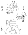
- Fig. 5 is explanatory views showing the connector cover part 93 of the upper cover member 90.
- Fig. 5(a) is a perspective view showing a connector part 94 and an accommodation part 95 of the connector cover part 93 which are viewed from an obliquely right upper side.
- Fig. 5(b) is a perspective view showing the connector part 94 and the accommodation part 95 which are viewed from an obliquely lower side, and
- Fig. 5(c) is a view showing the accommodation part 95 viewed in a radial direction.
- Fig. 6 is explanatory views showing the connector cover part 93.
- Fig. 6(a) is a view which is viewed from an upper side in the axial line X direction
- Fig. 6(b) is its perspective view
- Fig. 6(c) is an explanatory view showing attachment of a heat insulation member 946 to a terminal support part 940 of the connector cover part 93.
- Fig. 7 is explanatory views showing the connector part 94.
- Fig. 7(a) is a view which is viewed from a lower side in the axial line X direction
- Fig. 7(b) is a perspective view which is viewed from an obliquely lower side in the axial line X direction.
- the surrounding wall part 92 of the upper cover member 90 is formed in a ring shape when viewed in the axial direction of the axial line X.
- the surrounding wall part 92 is provided so as to surround an outer periphery of the outer stator core 59.
- a lower end 92b (see Fig. 3 ) of the surrounding wall part 92 is located on a lower side in the axial line X direction (fluid lead-out pipes 3 and 4 side) with respect to the coil terminals 56 and the drive coils 54 disposed on an inner side of the upper cover member 90 and the connector cover part 93. Therefore, water splashed on the surrounding wall part 92 is preferably prevented from reaching to conductive parts such as the coil terminals 56 and the drive coils 54.
- the cut-out area is the opening part 92a where the coil terminals 56 extended in the radial direction from the stator assembly 40 are passed through.
- the opening part 92a is formed in a height range from a lower end of the surrounding wall part 92 to the vicinity of the cover part 91 (see Fig. 5(b) ).
- An upper side 92a1 of the opening part 92a is extended in parallel to the cover part 91 at a position offset from the cover part 91 to a lower side (fluid lead-out pipes 3 and 4 side).
- Both sides 92a2 and 92a2 of the opening part 92a in the circumferential direction of the surrounding wall part 92 are extended in a straight shape along the axial line X and the opening part 92a is formed in a substantially rectangular shape when viewed in the radial direction (see Fig. 5(c) ).
- a protruded part 921 is provided at both side parts of the upper side 92a1 so as to protrude to an outer side in the radial direction.
- the circuit board 60 described above is abutted with the protruded parts 921 from an outer side in the radial direction (see Fig. 1 ). Positioning in the radial direction of the circuit board 60 is performed by the protruded parts 921.
- the surrounding wall part 92 of the upper cover member 90 is provided with an engaged part 922 with which an engaging arm 84 of a lower cover member 80 described below is engaged at a position opposite to the opening part 92a interposing the axial line X.
- the upper cover member 90 is integrally formed with the connector part 94 and the accommodation part 95 of the connector cover part 93.
- the surrounding wall part 92 of the upper cover member 90 is provided with the connector cover part 93 covering the opening part 92a on an outer side in the radial direction of the opening part 92a.
- the connector cover part 93 includes a connector part 94, which is extended to a lower side (fluid lead-out pipes 3 and 4 side) from an outer side in the radial direction of the surrounding wall part 92 and is located on a lower side (fluid lead-out pipes 3 and 4 side) with respect to the opening part 92a, the accommodation part 95 accommodating the circuit board 60 which connects the connector terminals 61 provided in the connector part 94 with the coil terminals 56, and a cap 96 which closes an opening 930 of the accommodation part 95.
- the connector part 94 is provided with a terminal support part 940 at a position to an outer side in the radial direction of the large diameter part 202.
- a plurality of the connector terminals 61 is provided so as to be separated from each other in the circumferential direction around the axial line X (see Fig. 3 ).
- Each of the connector terminals 61 is provided so as to penetrate through the terminal support part 940 in its thickness direction (axial line X direction). When viewed in the radial direction, each of the connector terminals 61 is located on a lower side with respect to the coil terminals 56 and is provided in a posture substantially perpendicular to the coil terminals 56.
- Each of the connector terminals 61 is connected with the corresponding coil terminal 56 through the circuit board 60.
- Each of the connector terminals 61 is connected with a land 601A of a corresponding wiring line by soldering formed so as to surround a terminal hole 601 in wiring lines provided in the circuit board 60 on a face of the circuit board 60 opposite to the terminal support part 940.
- each of the connector terminals 61 is connected with the corresponding wiring line by soldering in a state that the connector terminal 61 is inserted into the circular terminal hole 601 provided on one side of the circuit board 60.
- Connected parts (soldered parts) of the connector terminals 61 with the circuit board 60 are provided at positions offset to a lower side (terminal support part 940 side) by a distance of a predetermined height h in the axial line X direction from connected parts (soldered parts) of the coil terminals 56 with the circuit board 60. Further, in the circuit board 60 connecting the coil terminals 56 with the connector terminals 61, its one end part 60a side is extended in a direction along the axial line X and its the other end part 60b side is extended in a direction along a perpendicular direction to the axial line X with a curved part 60c as a boundary.
- the circuit board 60 is curved in a substantially L shape when viewed from a side face of the circuit board 60 (see Fig. 4(a) ).
- the support face 940b is a flat face which is perpendicular to the axial line X and the heat insulation member 946 having an insulation property is provided between the support face 940b and the circuit board 60 (see Fig. 4(b) ).
- the heat insulation member 946 is a member for restraining the connector terminals 61 supported by the terminal support part 940 from being inclined due to heat by which the terminal support part 940 may be softened when the circuit board 60 is soldered with the connector terminals 61.
- the heat insulation member 946 is a plate-shaped member formed in a rectangular shape (see Fig. 6(c) ) and is structured of glass epoxy.
- the heat insulation member 946 is provided with a thickness Wa which is thicker than a thickness Wb of the circuit board 60 (see Fig. 4(b) ) and a plurality of through-holes 946a penetrating through the heat insulation member 946 in its thickness direction is provided in a longitudinal direction of the heat insulation member 946 with spaces therebetween.
- the connector terminals 61 protruded from the terminal support part 940 are penetrated through the through-holes 946a of the heat insulation member 946 and are extended to an upper side.
- the heat insulation member 946 is disposed at a predetermined position of an upper face (face on the coil terminal 56 side) of the terminal support part 940 by the connector terminals 61 penetrated through the through-holes 946a.
- the heat insulation member 946 is formed so that its width Wc is smaller than a width Wd in the radial direction of the terminal support part 940.
- a side face 946b on an inner diameter side of the heat insulation member 946 is disposed at a position separated from an inclined face 940a on an inner diameter side of the terminal support part 940 to an outer side in the radial direction by a predetermined distance We.
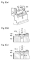
- Fig. 8(a) is an exploded perspective view showing the heat insulation member 946 and the terminal support part 940 which are viewed from an obliquely upper side.
- Fig. 8(b) is a cross-sectional view showing the circuit board 60, the heat insulation member 946 and a part of the terminal support member 940 which are viewed from an outer side in the radial direction in a case that an inner diameter d1 of the through-hole 946a of the heat insulation member 946 is smaller than an inner diameter d2 of the terminal hole 601 of the circuit board 60.
- FIG. 8(c) is a cross-sectional view showing the circuit board 60, the heat insulation member 946 and a part of the terminal support member 940 which are viewed from an outer side in the radial direction in a case that the inner diameter d1 of the through-hole 946a of the heat insulation member 946 is larger than the outer diameter d2 of the land 601A of the circuit board 60.
- the inner diameter d1 of the through-hole 946a of the heat insulation member 946 is larger than the diameter D1 of the connector terminal 61 and is formed to be smaller than two times of the diameter D1 (D ⁇ d1 ⁇ 2 x D1). Therefore, the heat insulation member 946 is positioned by inserting the connector terminals 61 into the through-holes 946a.
- the inner diameter d1 of the through-hole 946a of the heat insulation member 946 is preferably formed to be smaller than the outer diameter d2 of the land 601A formed around the terminal hole 601 of the circuit board 60. According to this structure, when the circuit board 60 is to be soldered with the connector terminal 61, the circuit board 60 is prevented from being deformed and got into the through-hole 946a of the heat insulation member 946 by a pressing force in a direction toward the heat insulation member 946 due to soldering and can be prevented from contacting with the terminal support member 940 (see the dotted line in Fig. 8(c) ).
- soldering heat is prevented from being directly transmitted to the terminal support member 940 through the circuit board 60 and thus the terminal support member 940 can be prevented from being softened by the heat and inclination of the connector terminal 61 can be preferably prevented.
- the connector terminals 61 which are penetrated through the heat insulation member 946 and are extended to an upper side (face on the rotor 30 side) are penetrated through the other end part 60b side of the circuit board 60.
- the tip end sides of the connector terminals 61 are soldered on a face of the circuit board 60 on an opposite side to the terminal support part 940.
- the heat insulation member 946 structured of glass epoxy whose melting temperature is higher than the terminal support part 940 is intervened between the circuit board 60 and the terminal support part 940. Therefore, heat of about 350°C generated at the time of soldering is prevented from transmitting to the terminal support part 940 made of mixed resin of polycarbonate and ABS resin and thereby the terminal support part 940 is prevented from being melted by the soldering heat.
- the connector terminals 61 supported by the terminal support part 940 may be inclined and, in this case, a problem may occur in connection of a mating connector (not shown) with the connector terminals 61.
- the thickness Wa of the heat insulation member 946 is set to be thicker than the thickness Wb of the circuit board 60. This is because the heat at the time of soldering is prevented from being transmitted to the terminal support part 940 side. Further, the heat insulation member 946 is structured of material having an insulation property and thereby adjacent connector terminals 61 are prevented from being short-circuited through the heat insulation member 946.
- the terminal support part 940 is provided with a surrounding wall part 941 which surrounds outer peripheries of the connector terminals 61 protruded to a lower side (the fluid lead-out pipes 3 and 4 side) from the terminal support part 940.
- the surrounding wall part 941 is structured of side wall parts 942 and 942 provided on both sides in a longitudinal direction of the terminal support part 940, an outer wall part 943 provided along a side edge on an outer side in the radial direction of the terminal support part 940, and an inner wall part 944 provided along a side edge on an inner side in the radial direction.
- a cut-out part 944a is formed which is cut out so as to leave two connecting beams 945 and 945 with the terminal support part 940 on an inner diameter side of the inner wall part 944 (obliquely right upper side in Fig. 7(b) ).
- the cut-out part 944a is provided with a width L3 (see Fig. 5(a) ) which is larger than a width L2 (see Fig. 3 ) of the circuit board 60.
- an engaging part 944b for engaging with an engagement projection (not shown) of a mating connector is provided at a center in a width direction of the cut-out part 944a.
- the connecting beams 945 and 945 are formed in a substantially rectangular shape when viewed from the axial line X side (inner diameter side) and are provided along an attaching and detaching direction of the mating connector to the connector part 94.
- the connecting beams 945 and 945 are provided so as to connect the inner wall part 944 with side edges on an inner diameter side of the terminal support part 940 for reinforcing the inner wall part 944 against a force applied to the engaging part 944b when the mating connector is to be pulled out.
- a force applied to the engaging part 944b (inner wall part 944) when the mating connector is to be pulled out can be transmitted (released) to the terminal support part 940 side and thus stress is prevented from being concentrated on a connected part between the inner wall part 944 and the side wall part 942 and the connected part is prevented from being broken.
- the connecting beams 945 and 945 are provided and thus, even when the side wall parts 942 and 942 are disposed in a separated state from each other, a sufficient strength can be secured. Therefore, the width L3 of the cut-out part 944a (see Fig. 5(b) ) can be set larger than the width L2 of the circuit board 60 (see Fig. 3 ).
- a connected part of the connecting beam 945 with the terminal support part 940 is provided with an inclined face 945a in which thickness of the connecting beam 945 becomes thinner toward the support face 940b side for the circuit board 60 (upper side in Fig. 4 ) of the terminal support part 940.
- a side face of the terminal support part 940 exposed in the cut-out part 944a is provided with an inclined face 940a which is inclined in a similar direction to the inclined face 945a.
- the space W1 between the connecting beam 945 and a reinforcing wall 82 of an attaching part 85 described below and the space W2 between the terminal support part 940 and the reinforcing wall 82 are set to be wider toward an upper side of the upper cover member 90.
- the outer stator core 59 and the upper cover member 90 are assembled in this order to the stator assembly 40 in which the circuit board 60 is soldered to the coil terminals 56 (see Fig. 3 ).
- a space Sa is secured to an inner diameter side of the terminal support part 940 for avoiding an interference with the coil terminals 56 and the circuit board 60 (see Fig. 4 ).
- the other end part 60b of the circuit board 60 is located at a position as shown by the dotted line in Fig. 4 just after the upper cover member 90 has been assembled. Therefore, it is required that the other end part 60b side is curved to an outer side in the radial direction from this state (see the arrow in the drawing) and that the terminal holes 601 (see Fig. 3 ) provided in the other end part 60b are engaged with the connector terminals 61 which are protruded to an upper side (cap 96 side) from an upper face (support face 940b) of the terminal support part 940.
- an inner diameter d3 of the terminal hole 601 provided in the other end part 60b of the circuit board 60 is the same as an inner diameter d1 of the through-hole 946a of the heat insulation member 946 and is formed to be larger than a diameter D1 of the connector terminal 61 supported by the terminal support part 940 but smaller than a diameter of two times of the diameter D1 (see Fig. 8 ).
- the reinforcing wall 82 of the attaching part 85 described below is located to an inner diameter side of the terminal support part 940 and thus, in a case that a space between the reinforcing wall 82 and the terminal support part 940 is small, the entire circuit board 60 is required to be curved largely when the other end part 60b side of the circuit board 60 is to be curved and thus a bending radius of the circuit board 60 becomes small.
- a length L1 in a longitudinal direction of the circuit board 60 (see Fig. 3 ) is required to make longer to give a margin for the length L1 of the circuit board 60.
- the terminal support part 940 side of the inner wall part 944 is cut out and an inner diameter side of the terminal support part 940 is exposed in an inside of the cut-out part 944a and, in this manner, the space Sa to the inner diameter side of the terminal support part 940 is widened.
- connecting beam 945 and the terminal support part 940 are respectively provided with the inclined faces 945a and 940a to widen the space to the reinforcing wall 82 and, in the support face 940b of the terminal support part 940, the connector terminals 61 are located in the vicinity of the inclined faces 945a and 940a.
- the length L1 in the longitudinal direction of the circuit board 60 can be shortened and, when the circuit board 60 is to be curved, a bending radius of the circuit board 60 can be increased.
- the inclined faces 940a and 945a are provided and thus the space is enlarged by amounts of the inclined faces 940a and 945a. Therefore, while the inclined faces 940a and 945a are functioned as a guide when the circuit board 60 is to be curved, a bending radius of the circuit board 60 when the circuit board 60 is to be curved can be enlarged.
- the inner wall part 944 is provided with the cut-out part 944a and thus the length L1 of the circuit board 60 can be shortened. Therefore, in a state that the other end part 60b side of the circuit board 60 is bent at a substantially 90 degrees with respect to the one end part 60a side, the curved part 60c of the circuit board 60 can be disposed at a position separated from the metal reinforcing wall 82.
- the side face 946b on an inner diameter side of the heat insulation member 946 is disposed at a position separated by a predetermined distance We to an outer side in the radial direction from the inclined face 940a on an inner diameter side of the terminal support part 940. Therefore, when the other end part 60b side of the circuit board 60 is to be curved to an outer side in the radial direction (see the arrow in Fig. 4(a) ), the other end part 60b is not caught by the heat insulation member 946. This is because that, if the other end part 60b of the circuit board 60 is caught by the heat insulation member 946, the heat insulation member 946 is lifted up by the circuit board 60 and may be come off from the connector terminals 61.
- the accommodation part 95 of the connector cover part 93 is adjacently provided to an upper side of the connector part 94.
- the accommodation part 95 is provided with an upper wall part 951 formed along an upper side 92a1 of the opening part 92a of the surrounding wall part 92 and side wall parts 952 and 952 formed along vertical sides 92a2 of the opening part 92a.
- the upper wall part 951 and the side wall parts 952 and 952 are protruded to an outer side in the radial direction from an outer peripheral face of the surrounding wall part 92 and are provided so as to surround the upper side and the both vertical sides of the opening part 92a provided in the surrounding wall part 92 when viewed in the radial direction for the axial line X.
- the side wall parts 952 and 952 are provided over the total lengths of the vertical sides 92a2 of the opening part 92a and their upper end parts are connected with both end parts in a longitudinal direction of the upper wall part 951.
- a lower end part side of the side wall part 952 is protruded in a direction separated from the surrounding wall part 92 toward a lower side (fluid lead-out pipes 3 and 4 side).
- the terminal support part 940 is integrally connected with a lower end of the protruded portion (protruded part 952c).
- the connector part 94 having the terminal support part 940 is held by the side wall parts 952 and 952 at a position separated to an outer side in a radial direction from the outer periphery of the surrounding wall part 92. Further, the protruded parts 952c on the lower end side of the side wall parts 952 and 952 function as ribs which secure support strength for the terminal support part 940.
- a peripheral wall (surrounding wall) surrounding the opening part 92a of the surrounding wall part 92 is formed by the terminal support part 940, the upper wall part 951 and the side wall parts 952 and 952.
- outer side faces of the side wall parts 952 in a circumferential direction around the axial line X are formed with step parts 954 at a position offset to an inner side from the outer peripheral part 953 of the side wall part 952.
- the outer peripheral part 953 side of the side wall part 952 with respect to the step part 954 is formed as an inner side fitting wall part 955 to which a fitting wall part of the cap 96 is fitted.
- the terminal support part 940 connected with lower ends of the side wall parts 952 is disposed in a posture that its upper face (support face 940b) is perpendicular to the axial line X.
- the support face 940b of the terminal support part 940 is located by a predetermined height h2 on an upper side of the cover part 91 side (cap 96 side) with respect to the upper end 943a of the outer wall part 943 of the connector part 94 (see Fig. 6 ).
- the terminal support part 940 is protruded in an inside of the opening 930 and a side edge 940c on the outer diameter side of the terminal support part 940 can be visually observed from an outer side in the radial direction.
- terminal support part 940 is, as described above, disposed at a position separated to an outer side in the radial direction from the surrounding wall part 92, and the upper face of the terminal support part 940 (support face 940b) can be also visually observed from an upper side of the opening 930 (cap 96 side).
- the heat insulation member 946 is disposed at a predetermined position on the upper face (support face 940b) of the terminal support part 940 by the connector terminals 61 which are penetrated through the through-holes 946a.
- the terminal support part 940 is not provided with a wall or the like for obstructing access to the terminal support part 940 on its outer side in the radial direction and on its upper side and thus attachment of the heat insulation member 946 to the terminal support part 940 can be easily performed.
- the upper cover member 90 is not formed on an outer side in the radial direction over a region from a side edge 940c of the terminal support part 940 to a position of the upper wall part 951 provided along the upper side 92a1 of the opening part 92a of the surrounding wall part 92. Therefore, an obstructive member is not existed when the heat insulation member 946 is to be attached to the terminal support part 940 and thus the heat insulation member 946 can be easily attached to the terminal support part 940.
- the side edge 940c of the terminal support part 940 is located on an inner side in the radial direction relative to the outer wall part 943 on the outer diameter side of the connector part 94 and is formed as an abutting face with which an abutting part 974 of the cap 96 described below is abutted.
- valve part 70 driven by the motor M will be described below.
- Fig. 9 is an exploded perspective view showing the lower cover member 80, the valve part 70, a table member 86 and the motor M in the valve drive device 1.
- the valve part 70 of the valve drive device 1 is a member which is rotationally driven by the motor M around the axial line X2 (see Fig. 9 ) of a center axial direction of a shaft member 73 described below whose cross section is a bar shape.
- the valve part 70 includes a gear 71 and a valve body 72.
- the gear 71 is an external gear meshing with the teeth part 33c provided on an outer periphery of the transmission shaft 33 of the motor M.
- the valve body 72 is a member formed in a substantially circular plate shape.
- a center of the valve body 72 is formed with a circular hole part and a bottom face of the valve body 72 is formed with a cut-out part.
- a portion of the bottom face of the valve body 72 where the cut-out part is not formed is structured to be capable of closing openings 3a and 4a of the fluid lead-out pipes 3 and 4 (see Fig. 9 ).
- connection member 15 is fitted and attached to a through hole 10c provided in the bottom plate part 10 from a lower side (fluid lead-out pipes 3 and 4 side) on an opposite side to the motor M.
- connection member 15 is formed with a hole part 15a for supporting the shaft member 73, which is a bar-shaped member whose cross-sectional shape in an axial direction is substantially circular, so as to be opened toward the fluid chamber S.
- an opening 3a of the fluid lead-out pipe 3 and an opening 4a of the fluid lead-out pipe 4 are located at positions to an outer side in the radial direction of the hole part 15a (see Fig. 9 ).
- the fluid lead-out pipes 3 and 4 are respectively provided so as to penetrate through the connection member 15 in the axial line X direction and are in communication with the fluid chamber S formed on an upper side (rotor 30 side) of the bottom plate part 10.
- a through hole 10d is provided at a position on an opposite side to the through hole 10c interposing the center hole part 10a and a fluid lead-in pipe 2 is fitted to the through hole 10d.
- the opening 2a of the fluid lead-in pipe 2 is opened in the fluid chamber S and the fluid lead-in pipe 2 is in communication with the fluid chamber S.
- the table member 86 is placed on an upper face 10b of the bottom plate part 10 (see Fig. 1 ).
- the table member 86 is structured so as to provide with a table part 87 and a plurality of leg parts 88 (88a and 88b) which are extended to a lower side (fluid lead-out pipes 3 and 4 side) from a peripheral edge part of the table part 87.
- the table part 87 is formed with a hole part 87a for passing the transmission shaft 33 at its center part.
- An arm part 89 having a support hole 89a is provided to an outer side in a radial direction of the hole part 87a along a circumferential direction around the axial line X.
- the circular plate part 203 of the partition 20 is abutted with the table part 87 to press it to a lower side on the bottom plate part 10 side (fluid lead-out pipes 3 and 4 side) to a position where the leg parts 88a are abutted with the bottom plate part 10.
- the leg part 88b is provided so as to protrude to an outer side in the radial direction relative to the leg part 88a and thus the table member 86 is held in an inside of the partition 20 in a state that the leg parts 88b are pressed against an inner periphery of the large diameter part 202 of the partition 20.
- the arm part 89 is capable of deforming in an axial direction independently from the table part 87 and, when the table member 86 is pressed to a lower side on the bottom plate part 10 side (fluid lead-out pipes 3 and 4 side), the arm part 89 urges the valve body 72 to a lower side on the bottom plate part 10 side (fluid lead-out pipes 3 and 4 side). Further, the support hole 89a of the arm part 89 is externally engaged and positioned by the shaft member 73 of the valve part 70. Therefore, the valve body 72 of the valve part 70 is always abutted with an upper face (face on the rotor 30 side) of the bottom plate part 10 by the arm part 89 and is positioned in the axial direction.
- the lower cover member 80 is externally fitted and fixed to the large diameter part 202 of the partition 20 which is fixed to an upper face (face on the rotor 30 side) of the bottom plate part 10.
- the lower cover member 80 is provided with an opening 81a into which the large diameter part 202 of the partition 20 is inserted at a center of the plate-shaped base part 81.
- An abutting piece 81b which is stood up toward an upper side in the axial line X direction is formed on an inner peripheral edge of the opening 81a at a plurality of positions in a circumferential direction around the axial line X.
- Each of the abutting pieces 81b is protruded toward the axial line X side from the opening 81a and is capable of elastically deforming to an outer side in the radial direction for the axial line X.
- the large diameter part 202 is inserted into the opening 81a of the base part 81 while expanding the abutting pieces 81b to an outer side in the radial direction and the lower cover member 80 is fixed to the partition 20.
- an attaching part 85 which is formed by bending toward a lower side in the axial line X direction (fluid lead-out pipes 3 and 4 side) is provided on one side in a width direction of the base part 81.
- the attaching part 85 is provided for attaching the valve drive device 1 to a refrigerator, which is an external structure, and is provided over the total length in a longitudinal direction of the base part 81.
- the attaching part 85 is formed with hole parts 85a into which a screw or the like is inserted.
- the hole parts 85a are located on outer sides in the radial direction relative to the fluid lead-in pipe 2 and the fluid lead-out pipe 3 in the radial direction for the axial line X in Fig. 1 where the attaching part 85 is viewed from a front face for avoiding an interference with the fluid lead-in pipe 2 and the fluid lead-out pipe 3.
- reinforcing walls 82 and 83 which are formed by bending toward an upper side in the axial line X direction are provided on both sides in a longitudinal direction of the base part 81.
- the reinforcing walls 82 and 83 are respectively provided over a total length in a width direction of the base part 81 and the upper cover member 90 (see Fig. 3 ) is placed on upper ends 82a and 83a of the reinforcing walls.
- the coil terminals 56 are located to an upper side (cover member 90 side) of the reinforcing wall 82 and the reinforcing wall 83 on the other side is provided with an engaging arm 84 for holding the lower cover member 80 and the upper cover member 90 in an engaging state.
- the engaging arm 84 in the reinforcing wall 83 is provided so as to be extended from a substantially center part in the width direction in a direction separated from the base part 81 (upper side), and an engaging part 84a is provided on an upper end side of the engaging arm 84 so as to protrude to the axial line X side.
- the engaging part 84a is engaged with an engaged part 922 of the upper cover member 90 when the upper cover member 90 is externally fitted and attached to the stator core 59 of the motor M and thereby coming-off of the upper cover member 90 from the lower cover member 80 is prevented.
- the reinforcing walls 82 and 83 are bent in an opposite direction (upper direction) to a bending direction (lower direction) of the attaching part 85 in the axial direction of the axial line X and flexural rigidity of the base part 81 of the lower cover member 80 is increased.
- the reinforcing walls 82 and 83 on both sides in its longitudinal direction are respectively bent in the same upper direction and thus, when the reinforcing walls 82 and 83 and the attaching part 85 are to be formed by bending, the bending work can be easily performed in comparison with a case that the reinforcing walls 82 and 83 are bent in different directions from each other (upper and lower directions) in the axial direction of the axial line X.
- the position where an end part of a winding coil extended from the drive coil 54 is bound is located on an inner side in the radial direction relative to the position where the circuit board 60 is soldered to the coil terminal 56 and thus the circuit board 60 is soldered to the coil terminal 56 at a position separated by a constant distance from the terminal holding part 55A.
- valve drive device in accordance with the present invention may be applied to a flow passage for fluid other than refrigerant in a refrigerator and may be appropriately modified to a structure for opening and closing a valve by the valve body 72.
Landscapes
- Engineering & Computer Science (AREA)
- Power Engineering (AREA)
- Motor Or Generator Frames (AREA)
- Insulation, Fastening Of Motor, Generator Windings (AREA)
Abstract
Description
- The present invention relates to a motor.
- A stator structure of a motor is disclosed in Patent Literature 1.
- [Patent Literature 1]
Japanese Patent Laid-Open No. 2007-282479 - In the stator structure of a motor disclosed in Patent Literature 1, a cover made of resin for accommodating a stator assembly is adopted. The cover is provided with a surrounding wall part which surrounds an outer periphery of the stator assembly. The surrounding wall part is integrally formed with a connector cover made of resin which covers a connector.
- An inner side of the cover and an inner side of the connector cover are communicated with each other through an opening part provided in the surrounding wall part. A plurality of coil terminals extended in a radial direction from the stator assembly is connected with corresponding connector terminals on an inner side of the connector cover through a flexible circuit board.
- A support member made of resin which supports the connector terminals is disposed on an inner side of the connector cover. A connected part of the circuit board with the connector terminals is connected with the connector terminals by soldering in a contacted state with the support member.
- The support member may be melted due to heat applied when soldering is performed depending on material of the support member and, in this case, support strength for the connector terminals is lowered in the support member.
- Therefore, when the connector terminals and the circuit board are connected with each other by soldering, it is required that soldering heat does not affect the support member.
- The present invention provides a motor, in which a coil terminal extended from a stator surrounding a rotor is connected with a connector terminal supported by a terminal support part made of resin through a wiring member in a plate shape having flexibility and, in a connected part of the connector terminal with the wiring member, the connector terminal protruded from the terminal support part penetrates through the wiring member contacted with the terminal support part and is connected by soldering with a face of the wiring member on an opposite side to the terminal support part and, in the motor, a heat insulation member having an insulation property is provided between the terminal support part and the wiring member.
- According to the present invention, the heat insulation member having an insulation property is provided between the terminal support part and the wiring member and thus influence of soldering heat when the connector terminal and the wiring member are to be connected with each other can be preferably prevented from being applied to the terminal support part.
-
-
Fig. 1 is a cross-sectional view showing a valve drive device in accordance with an embodiment of the present invention. -
Fig. 2 is the X1-X1 cross-sectional view inFig. 1 . -
Fig. 3 is an exploded perspective view showing a main part of a valve drive device. -
Fig.4 is explanatory views showing a connector cover part of an upper cover member. -
Fig. 5 is explanatory views showing an upper cover member. -
Fig. 6 is explanatory views showing a connector cover part of an upper cover member. -
Fig. 7 is explanatory views showing a connector part. -
Fig. 8 is explanatory views showing a relationship between a circuit board, a heat insulation member and a connector terminal. -
Fig. 9 is an exploded perspective view showing a motor side of a valve drive device. - An embodiment of the present invention will be described in detail below with reference to the accompanying drawings appropriately. The present invention is, as an example, applied to a valve drive device (gear unit) of a valve device structured to open and close a flow passage of refrigerant in a refrigerator.
- In the respective drawings, the same reference signs are used in common portions and duplicated explanation is omitted.
- In the following descriptions, a positional relationship of respective structural elements of a valve drive device will be appropriately described in which, with an axial line X of a rotation axis of a
rotor 30 of the valve drive device 1 shown inFig. 1 as a reference, therotor 30 side in an axial direction of the axial line X is referred to as an upper side and a fluid lead-outpipes -
Fig. 1 is a cross-sectional view showing a valve drive device 1 in accordance with an embodiment of the present invention.Fig. 2 is the X1-X1 cross-sectional view inFig. 1 .Fig. 3 is an exploded perspective view showing a motor M side of the valve drive device 1. - In
Fig. 3 , a portion formed of resin in astator assembly 40 is indicated by hatching. - As shown in
Figs. 1 through 3 , a valve drive device 1 in accordance with an embodiment of the present invention is a valve device which structures a flow passage where fluid (in this embodiment, refrigerant) can be circulated through a refrigerator (not shown) that is an external apparatus and is structured to lead out the fluid introduced to an inside of a fluid chamber S from the refrigerator through a fluid lead-inpipe 2 to the refrigerator through fluid lead-outpipes - In the valve drive device 1, a
valve part 70 is driven by a motor M and fluid introduced to the fluid chamber S is led out to the refrigerator side through the fluid lead-outpipes rotor 30. - In the valve drive device 1, a fluid chamber S is formed between a
bottom plate part 10 and apartition 20 by using thepartition 20 in a bottomed cylindrical shape which is fixed to an upper face (rotor 30 side face) of thebottom plate part 10. - In the valve drive device 1, the
partition 20 is provided so that itsbottom part 20a is located at an upper side (rotor 30 side) which is an opposite side to thebottom plate part 10. Thepartition 20 has an outward form which is enlarged in two steps in a direction separated from thebottom part 20a and is structured of asmall diameter part 201 on thebottom part 20a side and alarge diameter part 202 on thebottom plate part 10 side. - An outer circumferential edge of the
bottom plate part 10 is formed with astep part 11 over its entire periphery to which atip end 202a of thelarge diameter part 202 is fitted from an outer side. Thepartition 20 is fixed to thebottom plate part 10 in a state that thetip end 202a of thelarge diameter part 202 is fitted to thestep part 11. - Further, the valve drive device 1 is used in an arrangement state that a
rotor 30 of the motor M is disposed on an upper side and the fluid chamber S is disposed on a lower side (seeFig. 1 ). - The
rotor 30 of the motor M is provided on an inner side of thesmall diameter part 201 in a state externally fitted on theshaft member 21. - The
shaft member 21 in the valve drive device 1 is provided along the axial line X of the rotation axis of therotor 30. Oneend 21a of theshaft member 21 is supported by arecessed part 20b of thebottom part 20a and theother end 21b is brazed to ahole part 10a of thebottom plate part 10. Theshaft member 21 is provided in a rotation prevented state. - The
rotor 30 is rotatably supported by theshaft member 21 and, when the motor M is driven, therotor 30 is rotated around the axial line X. - The
rotor 30 is structured of abase part 31 having abearing part 31a which is externally fitted on theshaft member 21 and amagnet 32 on which an N-phase and an S-phase are alternately disposed in a circumferential direction around the axial line X. - The
magnet 32 is integrally formed with thebase part 31 by insert molding when therotor 30 is molded with resin. Themagnet 32 is provided over the entire periphery in the circumferential direction around the axial line X to thebase part 31. - A
transmission shaft 33 which transmits rotation of therotor 30 to avalve part 70 described below is inserted between thebearing part 31a and thebase part 31 and is fixed to a lower part on thebottom plate part 10 side of thebase part 31. Thetransmission shaft 33 is, similarly to therotor 30, rotatably supported by theshaft member 21 and is rotated together with therotor 30 around the axial line X. - The
transmission shaft 33 is extended to a lower side on thebottom plate part 10 side along the axial line X and itstip end part 33a is abutted with anupper face 10b of thebottom plate part 10. - In this embodiment, the
rotor 30 is urged to a lower side on thebottom plate part 10 side by a spring Sp which is externally fitted to oneend 21a side of theshaft member 21. Thetip end part 33a of thetransmission shaft 33 is always abutted with theupper face 10b of thebottom plate part 10 by an urging force of the spring Sp to position it in the axial direction of the axial line X of therotor 30. - A
large diameter part 33b whose diameter is larger than itstip end part 33a is provided to an upper side (rotor 30 side) of thetip end part 33a of thetransmission shaft 33. An outer periphery of thelarge diameter part 33b is provided with ateeth part 33c which is engaged with ateeth part 71g provided on an outer periphery of agear 71 described below (seeFig. 2 ). - As shown in
Fig. 2 , thesmall diameter part 201 of thepartition 20 which accommodates therotor 30 is formed in a tube shape surrounding themagnet 32 of therotor 30 with a predetermined space therebetween. Astator assembly 40 is externally fitted and attached to an outer periphery of thesmall diameter part 201. - In this embodiment, a
circular plate part 203 connecting thesmall diameter part 201 with thelarge diameter part 202 is provided so as to be perpendicular to the axial line X. Thestator assembly 40 externally fitted to thesmall diameter part 201 is positioned by thecircular plate part 203 and twostator assemblies - The
magnet 32 of therotor 30 is driven by magnetic force from thestator assembly 40 described below through thepartition 20 and thus thepartition 20 is structured of non-magnetic material. Further, thepartition 20 is structured of metal so as to withstand pressure in the fluid chamber S. Therefore, thepartition 20 is structured of stainless steel which is nonmagnetic metal. - As shown in
Fig. 2 , thestator assembly 40 includes twostator assemblies outer stator core 59 which surrounds outer peripheries of thestator assemblies stator assembly 40. - The
outer stator core 59 is, similarly toinner stator cores stator assemblies outer stator core 59 and theinner stator cores outer stator core 59 and theinner stator cores - Each of the
stator assemblies drive coil 54 wound around an outer periphery of abobbin 53 is disposed between a pair ofinner stator cores - In the
stator assembly 40, thebobbin 53 is a resin molded body (insulator) in which theinner stator cores stator assemblies terminal holding part 55 described below. -
Fig. 4(a) is an enlarged cross-sectional view showing a main part inFig. 1 andFig. 4(b) is an enlarged view showing an area A inFig. 4(a) . - As shown in
Fig. 4 , theinner stator cores flange parts pole teeth flange parts pole teeth flange parts - A pair of the
inner stator cores stator assemblies respective pole teeth pole teeth 511 of oneinner stator core 51 and thepole teeth 521 of the otherinner stator core 52 are alternately and adjacently disposed to each other in the circumferential direction around the axial line X. - A
base part 530 in a cylindrical shape of thebobbin 53 whose outer periphery is wound with a coil is located on an outer side in a radial direction of thepole teeth Flange parts base part 530 in the axial direction of the axial line X over the entire periphery in the circumferential direction around the axial line X. - As shown in
Fig. 2 , in thestator assembly 40, theinner stator core 51 of thestator assembly 50A and theinner stator core 52 of thestator assembly 50B are provided in a state that theflange parts 510 and 520 (seeFig. 4 ) are contacted with each other in the axial direction of the axial line X. - The
flange parts flange parts - In the
stator assembly 40 in which theinner stator cores pole teeth base part 530 of thebobbin 53. Faces on thedrive coil 54 side of theflange parts flange parts - In the
stator assembly 40, a ring-shaped attaching part 57 (seeFigs. 2 and3 ) is formed by using resin material covering an upper face on an inner diameter side of theflange part 510 of thestator assembly 50B. Afitting wall 91c of anupper cover member 90 described below is internally fitted and attached to the attachingpart 57. - Further, a ring-shaped abutting part 58 (see
Fig. 2 ) is formed by using resin material covering an under face on an inner diameter side of theflange part 520 of thestator assembly 50A. The abuttingpart 58 is abutted with thecircular plate part 203 at a boundary between thesmall diameter part 201 and thelarge diameter part 202 when thestator assembly 40 is externally fitted to thesmall diameter part 201 of thepartition 20 in the axial line X direction. Therefore, positioning in the axial direction of thestator assembly 40 is performed by the abuttingpart 58 which is abutted with thecircular plate part 203. - As shown in
Fig. 4 , theflange parts parts parts respective flange parts terminal holding part 55 is provided by utilizing the portions of the cut-outparts - The
terminal holding part 55B of thestator assembly 50B is provided so as to straddle over the cut-outparts flange parts - The
terminal holding part 55B is integrally formed with theflange parts bobbin 53 which are located on both sides of theflange parts - A
terminal holding part 55A of thestator assembly 50A is provided in the cut-outpart 520b of theflange part 520 of theinner stator core 52. - The
terminal holding part 55A is integrally formed with theflange part 532 of thebobbin 53 of thestator assembly 50A and has a predetermined thickness in the axial direction of the axial line X. - The
terminal holding part 55A of thestator assembly 50A and theterminal holding part 55B of thestator assembly 50B are provided with a space therebetween in the axial line X direction. - A plurality of
coil terminals 56 is press-fitted and supported by theterminal holding parts stator assemblies coil terminals 56 is provided so as to be protruded to an outer side in the radial direction from thestator assembly 40 and base ends of thecoil terminals 56 are located in the cut-outparts - Therefore, the
outer stator core 59 which is externally fitted and attached to thestator assembly 40 is provided with a cut-out part 593 (seeFig. 3 ) in a surroundingwall part 592 which surrounds the outer peripheries of thestator assemblies coil terminals 56. In addition, a surroundingwall part 92 of anupper cover member 90 described below is also provided with anopening part 92a for avoiding an interference with the coil terminals 56 (seeFig. 1 ). - The
outer stator core 59 is, as shown inFig. 3 , formed in a bottomed cylindrical shape and is provided with anopening 591a at a center part of thebottom part 591 so that thebottom part 20a of thepartition 20 can be inserted. A surroundingwall part 592 which is provided over the entire periphery of thebottom part 591 is formed in a cylindrical shape which surrounds over the entire periphery of theflange parts stator assemblies - As shown in
Fig. 4 , thecoil terminal 56 is a conductive pin which is formed in a bar shape extended in a straight shape. Thecoil terminals 56 are penetrated through theopening part 92a provided in theupper cover member 90 and their tip end sides are located in an inside of a connector cover part 93 (accommodation part 95). - In this embodiment, end parts (not shown) of a winding coil extended from the drive coil 54 (coil of A-phase) of the
stator assembly 50A are bound to terminal holdingpart 55A sides of thecoil terminals 56 held by theterminal holding part 55A, and end parts (not shown) of a winding coil extended from the drive coil 54 (coil of B-phase) of thestator assembly 50B are bound to terminal holdingpart 55B sides of thecoil terminals 56 held by theterminal holding part 55B. - The
respective coil terminals 56 supported by theterminal holding parts corresponding connector terminals 61 through a common flexible circuit board 60 (hereinafter, also referred to as a circuit board 60) structured of polyimide resin. Each of thecoil terminals 56 is connected by soldering with a corresponding wiring line of wiring lines provided on thecircuit board 60 on a face of thecircuit board 60 opposite to thedrive coil 54. - As shown in
Figs. 1 through 3 , anupper cover member 90 is a member accommodating thestator assembly 40 and theouter stator core 59 of the motor M and is integrally formed with acover part 91 covering an upper face of thestator assembly 40 and a surroundingwall part 92 which surrounds an outer periphery of theouter stator core 59. The surroundingwall part 92 is integrally formed with aconnector cover part 93. - The
upper cover member 90 is formed of mixed resin of polycarbonate and ABS resin by resin molding. -
Fig. 5 is explanatory views showing theconnector cover part 93 of theupper cover member 90.Fig. 5(a) is a perspective view showing aconnector part 94 and anaccommodation part 95 of theconnector cover part 93 which are viewed from an obliquely right upper side.Fig. 5(b) is a perspective view showing theconnector part 94 and theaccommodation part 95 which are viewed from an obliquely lower side, andFig. 5(c) is a view showing theaccommodation part 95 viewed in a radial direction. -
Fig. 6 is explanatory views showing theconnector cover part 93.Fig. 6(a) is a view which is viewed from an upper side in the axial line X direction,Fig. 6(b) is its perspective view, andFig. 6(c) is an explanatory view showing attachment of aheat insulation member 946 to aterminal support part 940 of theconnector cover part 93. -
Fig. 7 is explanatory views showing theconnector part 94.Fig. 7(a) is a view which is viewed from a lower side in the axial line X direction andFig. 7(b) is a perspective view which is viewed from an obliquely lower side in the axial line X direction. - As shown in
Fig. 5 , the surroundingwall part 92 of theupper cover member 90 is formed in a ring shape when viewed in the axial direction of the axial line X. In the valve drive device 1, the surroundingwall part 92 is provided so as to surround an outer periphery of theouter stator core 59. - A
lower end 92b (seeFig. 3 ) of the surroundingwall part 92 is located on a lower side in the axial line X direction (fluid lead-outpipes coil terminals 56 and the drive coils 54 disposed on an inner side of theupper cover member 90 and theconnector cover part 93. Therefore, water splashed on the surroundingwall part 92 is preferably prevented from reaching to conductive parts such as thecoil terminals 56 and the drive coils 54. - In the surrounding
wall part 92, when viewed in the radial direction, an area interfering with thecoil terminals 56 described above is cut out. The cut-out area is theopening part 92a where thecoil terminals 56 extended in the radial direction from thestator assembly 40 are passed through. - In the surrounding
wall part 92, theopening part 92a is formed in a height range from a lower end of the surroundingwall part 92 to the vicinity of the cover part 91 (seeFig. 5(b) ). An upper side 92a1 of theopening part 92a is extended in parallel to thecover part 91 at a position offset from thecover part 91 to a lower side (fluid lead-outpipes - Both sides 92a2 and 92a2 of the
opening part 92a in the circumferential direction of the surroundingwall part 92 are extended in a straight shape along the axial line X and theopening part 92a is formed in a substantially rectangular shape when viewed in the radial direction (seeFig. 5(c) ). - In the
opening part 92a, aprotruded part 921 is provided at both side parts of the upper side 92a1 so as to protrude to an outer side in the radial direction. Thecircuit board 60 described above is abutted with the protrudedparts 921 from an outer side in the radial direction (seeFig. 1 ). Positioning in the radial direction of thecircuit board 60 is performed by the protrudedparts 921. - The surrounding
wall part 92 of theupper cover member 90 is provided with anengaged part 922 with which anengaging arm 84 of alower cover member 80 described below is engaged at a position opposite to theopening part 92a interposing the axial line X. - The
upper cover member 90 is integrally formed with theconnector part 94 and theaccommodation part 95 of theconnector cover part 93. - As shown in
Fig. 3 , the surroundingwall part 92 of theupper cover member 90 is provided with theconnector cover part 93 covering theopening part 92a on an outer side in the radial direction of theopening part 92a. - The
connector cover part 93 includes aconnector part 94, which is extended to a lower side (fluid lead-outpipes wall part 92 and is located on a lower side (fluid lead-outpipes opening part 92a, theaccommodation part 95 accommodating thecircuit board 60 which connects theconnector terminals 61 provided in theconnector part 94 with thecoil terminals 56, and acap 96 which closes anopening 930 of theaccommodation part 95. - As shown in
Fig. 4 , theconnector part 94 is provided with aterminal support part 940 at a position to an outer side in the radial direction of thelarge diameter part 202. In theterminal support part 940, a plurality of theconnector terminals 61 is provided so as to be separated from each other in the circumferential direction around the axial line X (seeFig. 3 ). - Each of the
connector terminals 61 is provided so as to penetrate through theterminal support part 940 in its thickness direction (axial line X direction). When viewed in the radial direction, each of theconnector terminals 61 is located on a lower side with respect to thecoil terminals 56 and is provided in a posture substantially perpendicular to thecoil terminals 56. - Each of the
connector terminals 61 is connected with the correspondingcoil terminal 56 through thecircuit board 60. Each of theconnector terminals 61 is connected with aland 601A of a corresponding wiring line by soldering formed so as to surround aterminal hole 601 in wiring lines provided in thecircuit board 60 on a face of thecircuit board 60 opposite to theterminal support part 940. - In this embodiment, each of the
connector terminals 61 is connected with the corresponding wiring line by soldering in a state that theconnector terminal 61 is inserted into the circularterminal hole 601 provided on one side of thecircuit board 60. - Connected parts (soldered parts) of the
connector terminals 61 with thecircuit board 60 are provided at positions offset to a lower side (terminal support part 940 side) by a distance of a predetermined height h in the axial line X direction from connected parts (soldered parts) of thecoil terminals 56 with thecircuit board 60. Further, in thecircuit board 60 connecting thecoil terminals 56 with theconnector terminals 61, its oneend part 60a side is extended in a direction along the axial line X and its theother end part 60b side is extended in a direction along a perpendicular direction to the axial line X with acurved part 60c as a boundary. Thecircuit board 60 is curved in a substantially L shape when viewed from a side face of the circuit board 60 (seeFig. 4(a) ). - Therefore, restoring force in a direction for returning the
circuit board 60 to an original shape is acted on the connected part (theother end part 60b) side of thecircuit board 60 with theconnector terminals 61. Theother end part 60b side of thecircuit board 60 is pressed against an upper face of the terminal support part 940 (support face 940b for the circuit board 60) by the restoring force. - In this embodiment, the
support face 940b is a flat face which is perpendicular to the axial line X and theheat insulation member 946 having an insulation property is provided between thesupport face 940b and the circuit board 60 (seeFig. 4(b) ). - The
heat insulation member 946 is a member for restraining theconnector terminals 61 supported by theterminal support part 940 from being inclined due to heat by which theterminal support part 940 may be softened when thecircuit board 60 is soldered with theconnector terminals 61. - The
heat insulation member 946 is a plate-shaped member formed in a rectangular shape (seeFig. 6(c) ) and is structured of glass epoxy. - The
heat insulation member 946 is provided with a thickness Wa which is thicker than a thickness Wb of the circuit board 60 (seeFig. 4(b) ) and a plurality of through-holes 946a penetrating through theheat insulation member 946 in its thickness direction is provided in a longitudinal direction of theheat insulation member 946 with spaces therebetween. - In this embodiment, the
connector terminals 61 protruded from theterminal support part 940 are penetrated through the through-holes 946a of theheat insulation member 946 and are extended to an upper side. Theheat insulation member 946 is disposed at a predetermined position of an upper face (face on thecoil terminal 56 side) of theterminal support part 940 by theconnector terminals 61 penetrated through the through-holes 946a. - The
heat insulation member 946 is formed so that its width Wc is smaller than a width Wd in the radial direction of theterminal support part 940. A side face 946b on an inner diameter side of theheat insulation member 946 is disposed at a position separated from aninclined face 940a on an inner diameter side of theterminal support part 940 to an outer side in the radial direction by a predetermined distance We. -
Fig. 8(a) is an exploded perspective view showing theheat insulation member 946 and theterminal support part 940 which are viewed from an obliquely upper side.Fig. 8(b) is a cross-sectional view showing thecircuit board 60, theheat insulation member 946 and a part of theterminal support member 940 which are viewed from an outer side in the radial direction in a case that an inner diameter d1 of the through-hole 946a of theheat insulation member 946 is smaller than an inner diameter d2 of theterminal hole 601 of thecircuit board 60.Fig. 8(c) is a cross-sectional view showing thecircuit board 60, theheat insulation member 946 and a part of theterminal support member 940 which are viewed from an outer side in the radial direction in a case that the inner diameter d1 of the through-hole 946a of theheat insulation member 946 is larger than the outer diameter d2 of theland 601A of thecircuit board 60. - In
Figs. 8(b) and 8(c) , theconnector terminal 61 is not shown. - As shown in
Fig. 8(a) , the inner diameter d1 of the through-hole 946a of theheat insulation member 946 is larger than the diameter D1 of theconnector terminal 61 and is formed to be smaller than two times of the diameter D1 (D <d1 < 2 x D1). Therefore, theheat insulation member 946 is positioned by inserting theconnector terminals 61 into the through-holes 946a. - In addition, as shown in
Fig. 8(b) , the inner diameter d1 of the through-hole 946a of theheat insulation member 946 is preferably formed to be smaller than the outer diameter d2 of theland 601A formed around theterminal hole 601 of thecircuit board 60. According to this structure, when thecircuit board 60 is to be soldered with theconnector terminal 61, thecircuit board 60 is prevented from being deformed and got into the through-hole 946a of theheat insulation member 946 by a pressing force in a direction toward theheat insulation member 946 due to soldering and can be prevented from contacting with the terminal support member 940 (see the dotted line inFig. 8(c) ). - Therefore, according to this structure, soldering heat is prevented from being directly transmitted to the
terminal support member 940 through thecircuit board 60 and thus theterminal support member 940 can be prevented from being softened by the heat and inclination of theconnector terminal 61 can be preferably prevented. - The
connector terminals 61 which are penetrated through theheat insulation member 946 and are extended to an upper side (face on therotor 30 side) are penetrated through theother end part 60b side of thecircuit board 60. The tip end sides of theconnector terminals 61 are soldered on a face of thecircuit board 60 on an opposite side to theterminal support part 940. - In this embodiment, the
heat insulation member 946 structured of glass epoxy whose melting temperature is higher than theterminal support part 940 is intervened between thecircuit board 60 and theterminal support part 940. Therefore, heat of about 350°C generated at the time of soldering is prevented from transmitting to theterminal support part 940 made of mixed resin of polycarbonate and ABS resin and thereby theterminal support part 940 is prevented from being melted by the soldering heat. - If the
terminal support part 940 is melted by heat, theconnector terminals 61 supported by theterminal support part 940 may be inclined and, in this case, a problem may occur in connection of a mating connector (not shown) with theconnector terminals 61. - In this embodiment, the thickness Wa of the
heat insulation member 946 is set to be thicker than the thickness Wb of thecircuit board 60. This is because the heat at the time of soldering is prevented from being transmitted to theterminal support part 940 side. Further, theheat insulation member 946 is structured of material having an insulation property and therebyadjacent connector terminals 61 are prevented from being short-circuited through theheat insulation member 946. - As shown in
Fig. 7(b) , theterminal support part 940 is provided with a surroundingwall part 941 which surrounds outer peripheries of theconnector terminals 61 protruded to a lower side (the fluid lead-outpipes terminal support part 940. The surroundingwall part 941 is structured ofside wall parts terminal support part 940, anouter wall part 943 provided along a side edge on an outer side in the radial direction of theterminal support part 940, and aninner wall part 944 provided along a side edge on an inner side in the radial direction. - A cut-out
part 944a is formed which is cut out so as to leave two connectingbeams terminal support part 940 on an inner diameter side of the inner wall part 944 (obliquely right upper side inFig. 7(b) ). The cut-outpart 944a is provided with a width L3 (seeFig. 5(a) ) which is larger than a width L2 (seeFig. 3 ) of thecircuit board 60. - As shown in
Fig. 7 , anengaging part 944b for engaging with an engagement projection (not shown) of a mating connector is provided at a center in a width direction of the cut-outpart 944a. - The connecting
beams connector part 94. - The connecting
beams inner wall part 944 with side edges on an inner diameter side of theterminal support part 940 for reinforcing theinner wall part 944 against a force applied to theengaging part 944b when the mating connector is to be pulled out. A force applied to theengaging part 944b (inner wall part 944) when the mating connector is to be pulled out can be transmitted (released) to theterminal support part 940 side and thus stress is prevented from being concentrated on a connected part between theinner wall part 944 and theside wall part 942 and the connected part is prevented from being broken. - In the
connector part 94 in this embodiment, the connectingbeams side wall parts part 944a (seeFig. 5(b) ) can be set larger than the width L2 of the circuit board 60 (seeFig. 3 ). - A connected part of the connecting
beam 945 with theterminal support part 940 is provided with aninclined face 945a in which thickness of the connectingbeam 945 becomes thinner toward thesupport face 940b side for the circuit board 60 (upper side inFig. 4 ) of theterminal support part 940. - In addition, a side face of the
terminal support part 940 exposed in the cut-outpart 944a is provided with aninclined face 940a which is inclined in a similar direction to theinclined face 945a. - Therefore, as shown in
Fig. 4 , the space W1 between the connectingbeam 945 and a reinforcingwall 82 of an attachingpart 85 described below and the space W2 between theterminal support part 940 and the reinforcingwall 82 are set to be wider toward an upper side of theupper cover member 90. - In this embodiment, the
outer stator core 59 and theupper cover member 90 are assembled in this order to thestator assembly 40 in which thecircuit board 60 is soldered to the coil terminals 56 (seeFig. 3 ). In theconnector cover part 93, a space Sa is secured to an inner diameter side of theterminal support part 940 for avoiding an interference with thecoil terminals 56 and the circuit board 60 (seeFig. 4 ). - The
other end part 60b of thecircuit board 60 is located at a position as shown by the dotted line inFig. 4 just after theupper cover member 90 has been assembled. Therefore, it is required that theother end part 60b side is curved to an outer side in the radial direction from this state (see the arrow in the drawing) and that the terminal holes 601 (seeFig. 3 ) provided in theother end part 60b are engaged with theconnector terminals 61 which are protruded to an upper side (cap 96 side) from an upper face (support face 940b) of theterminal support part 940. - In accordance with an embodiment of the present invention, it is preferable that an inner diameter d3 of the
terminal hole 601 provided in theother end part 60b of thecircuit board 60 is the same as an inner diameter d1 of the through-hole 946a of theheat insulation member 946 and is formed to be larger than a diameter D1 of theconnector terminal 61 supported by theterminal support part 940 but smaller than a diameter of two times of the diameter D1 (seeFig. 8 ). - However, the reinforcing
wall 82 of the attachingpart 85 described below is located to an inner diameter side of theterminal support part 940 and thus, in a case that a space between the reinforcingwall 82 and theterminal support part 940 is small, theentire circuit board 60 is required to be curved largely when theother end part 60b side of thecircuit board 60 is to be curved and thus a bending radius of thecircuit board 60 becomes small. - Therefore, a length L1 in a longitudinal direction of the circuit board 60 (see
Fig. 3 ) is required to make longer to give a margin for the length L1 of thecircuit board 60. - In this embodiment, the
terminal support part 940 side of theinner wall part 944 is cut out and an inner diameter side of theterminal support part 940 is exposed in an inside of the cut-outpart 944a and, in this manner, the space Sa to the inner diameter side of theterminal support part 940 is widened. - In addition, the connecting
beam 945 and theterminal support part 940 are respectively provided with theinclined faces wall 82 and, in thesupport face 940b of theterminal support part 940, theconnector terminals 61 are located in the vicinity of theinclined faces - Therefore, in comparison with a case that the cut-out
part 944a is not provided, the length L1 in the longitudinal direction of thecircuit board 60 can be shortened and, when thecircuit board 60 is to be curved, a bending radius of thecircuit board 60 can be increased. - Further, the
inclined faces inclined faces inclined faces circuit board 60 is to be curved, a bending radius of thecircuit board 60 when thecircuit board 60 is to be curved can be enlarged. - Further, the
inner wall part 944 is provided with the cut-outpart 944a and thus the length L1 of thecircuit board 60 can be shortened. Therefore, in a state that theother end part 60b side of thecircuit board 60 is bent at a substantially 90 degrees with respect to the oneend part 60a side, thecurved part 60c of thecircuit board 60 can be disposed at a position separated from themetal reinforcing wall 82. - In this embodiment, as described above, the side face 946b on an inner diameter side of the
heat insulation member 946 is disposed at a position separated by a predetermined distance We to an outer side in the radial direction from theinclined face 940a on an inner diameter side of theterminal support part 940. Therefore, when theother end part 60b side of thecircuit board 60 is to be curved to an outer side in the radial direction (see the arrow inFig. 4(a) ), theother end part 60b is not caught by theheat insulation member 946. This is because that, if theother end part 60b of thecircuit board 60 is caught by theheat insulation member 946, theheat insulation member 946 is lifted up by thecircuit board 60 and may be come off from theconnector terminals 61. - As shown in
Fig. 5 , theaccommodation part 95 of theconnector cover part 93 is adjacently provided to an upper side of theconnector part 94. Theaccommodation part 95 is provided with anupper wall part 951 formed along an upper side 92a1 of theopening part 92a of the surroundingwall part 92 andside wall parts opening part 92a. - The
upper wall part 951 and theside wall parts wall part 92 and are provided so as to surround the upper side and the both vertical sides of theopening part 92a provided in the surroundingwall part 92 when viewed in the radial direction for the axial line X. - The
side wall parts opening part 92a and their upper end parts are connected with both end parts in a longitudinal direction of theupper wall part 951. - As shown in
Fig. 6(b) , a lower end part side of theside wall part 952 is protruded in a direction separated from the surroundingwall part 92 toward a lower side (fluid lead-outpipes terminal support part 940 is integrally connected with a lower end of the protruded portion (protrudedpart 952c). - Therefore, the
connector part 94 having theterminal support part 940 is held by theside wall parts wall part 92. Further, the protrudedparts 952c on the lower end side of theside wall parts terminal support part 940. - When a portion provided with the
terminal support part 940 is viewed in the radial direction for the axial line X, a peripheral wall (surrounding wall) surrounding theopening part 92a of the surroundingwall part 92 is formed by theterminal support part 940, theupper wall part 951 and theside wall parts - In addition, outer side faces of the
side wall parts 952 in a circumferential direction around the axial line X are formed withstep parts 954 at a position offset to an inner side from the outerperipheral part 953 of theside wall part 952. The outerperipheral part 953 side of theside wall part 952 with respect to thestep part 954 is formed as an inner sidefitting wall part 955 to which a fitting wall part of thecap 96 is fitted. - The
terminal support part 940 connected with lower ends of theside wall parts 952 is disposed in a posture that its upper face (support face 940b) is perpendicular to the axial line X. Thesupport face 940b of theterminal support part 940 is located by a predetermined height h2 on an upper side of thecover part 91 side (cap 96 side) with respect to theupper end 943a of theouter wall part 943 of the connector part 94 (seeFig. 6 ). - Therefore, when the
opening 930 of theconnector cover part 93 is viewed from an outer side in the radial direction for the axial line X, theterminal support part 940 is protruded in an inside of theopening 930 and aside edge 940c on the outer diameter side of theterminal support part 940 can be visually observed from an outer side in the radial direction. - In addition, the
terminal support part 940 is, as described above, disposed at a position separated to an outer side in the radial direction from the surroundingwall part 92, and the upper face of the terminal support part 940 (support face 940b) can be also visually observed from an upper side of the opening 930 (cap 96 side). - As described above, in this embodiment, the
heat insulation member 946 is disposed at a predetermined position on the upper face (support face 940b) of theterminal support part 940 by theconnector terminals 61 which are penetrated through the through-holes 946a. - In this case, the
terminal support part 940 is not provided with a wall or the like for obstructing access to theterminal support part 940 on its outer side in the radial direction and on its upper side and thus attachment of theheat insulation member 946 to theterminal support part 940 can be easily performed. - Specifically, the
upper cover member 90 is not formed on an outer side in the radial direction over a region from aside edge 940c of theterminal support part 940 to a position of theupper wall part 951 provided along the upper side 92a1 of theopening part 92a of the surroundingwall part 92. Therefore, an obstructive member is not existed when theheat insulation member 946 is to be attached to theterminal support part 940 and thus theheat insulation member 946 can be easily attached to theterminal support part 940. - The
side edge 940c of theterminal support part 940 is located on an inner side in the radial direction relative to theouter wall part 943 on the outer diameter side of theconnector part 94 and is formed as an abutting face with which anabutting part 974 of thecap 96 described below is abutted. - Next, the
valve part 70 driven by the motor M will be described below. -
Fig. 9 is an exploded perspective view showing thelower cover member 80, thevalve part 70, atable member 86 and the motor M in the valve drive device 1. - The
valve part 70 of the valve drive device 1 is a member which is rotationally driven by the motor M around the axial line X2 (seeFig. 9 ) of a center axial direction of ashaft member 73 described below whose cross section is a bar shape. Thevalve part 70 includes agear 71 and avalve body 72. - The
gear 71 is an external gear meshing with theteeth part 33c provided on an outer periphery of thetransmission shaft 33 of the motor M. - The
valve body 72 is a member formed in a substantially circular plate shape. A center of thevalve body 72 is formed with a circular hole part and a bottom face of thevalve body 72 is formed with a cut-out part. A portion of the bottom face of thevalve body 72 where the cut-out part is not formed is structured to be capable of closingopenings pipes 3 and 4 (seeFig. 9 ). - A
connection member 15 is fitted and attached to a throughhole 10c provided in thebottom plate part 10 from a lower side (fluid lead-outpipes - A center part of the
connection member 15 is formed with ahole part 15a for supporting theshaft member 73, which is a bar-shaped member whose cross-sectional shape in an axial direction is substantially circular, so as to be opened toward the fluid chamber S. In theconnection member 15, anopening 3a of the fluid lead-outpipe 3 and anopening 4a of the fluid lead-outpipe 4 are located at positions to an outer side in the radial direction of thehole part 15a (seeFig. 9 ). - The fluid lead-out
pipes connection member 15 in the axial line X direction and are in communication with the fluid chamber S formed on an upper side (rotor 30 side) of thebottom plate part 10. - In the
bottom plate part 10, a throughhole 10d is provided at a position on an opposite side to the throughhole 10c interposing thecenter hole part 10a and a fluid lead-inpipe 2 is fitted to the throughhole 10d. In this state, theopening 2a of the fluid lead-inpipe 2 is opened in the fluid chamber S and the fluid lead-inpipe 2 is in communication with the fluid chamber S. - As shown in
Fig. 9 , thetable member 86 is placed on anupper face 10b of the bottom plate part 10 (seeFig. 1 ). Thetable member 86 is structured so as to provide with atable part 87 and a plurality of leg parts 88 (88a and 88b) which are extended to a lower side (fluid lead-outpipes table part 87. - The
table part 87 is formed with ahole part 87a for passing thetransmission shaft 33 at its center part. Anarm part 89 having asupport hole 89a is provided to an outer side in a radial direction of thehole part 87a along a circumferential direction around the axial line X. - In this embodiment, when the
partition 20 is fixed to thebottom plate part 10, thecircular plate part 203 of thepartition 20 is abutted with thetable part 87 to press it to a lower side on thebottom plate part 10 side (fluid lead-outpipes leg parts 88a are abutted with thebottom plate part 10. - In this case, the
leg part 88b is provided so as to protrude to an outer side in the radial direction relative to theleg part 88a and thus thetable member 86 is held in an inside of thepartition 20 in a state that theleg parts 88b are pressed against an inner periphery of thelarge diameter part 202 of thepartition 20. - The
arm part 89 is capable of deforming in an axial direction independently from thetable part 87 and, when thetable member 86 is pressed to a lower side on thebottom plate part 10 side (fluid lead-outpipes arm part 89 urges thevalve body 72 to a lower side on thebottom plate part 10 side (fluid lead-outpipes support hole 89a of thearm part 89 is externally engaged and positioned by theshaft member 73 of thevalve part 70. Therefore, thevalve body 72 of thevalve part 70 is always abutted with an upper face (face on therotor 30 side) of thebottom plate part 10 by thearm part 89 and is positioned in the axial direction. - As shown in
Fig. 2 , thelower cover member 80 is externally fitted and fixed to thelarge diameter part 202 of thepartition 20 which is fixed to an upper face (face on therotor 30 side) of thebottom plate part 10. - The
lower cover member 80 is provided with anopening 81a into which thelarge diameter part 202 of thepartition 20 is inserted at a center of the plate-shapedbase part 81. Anabutting piece 81b which is stood up toward an upper side in the axial line X direction is formed on an inner peripheral edge of theopening 81a at a plurality of positions in a circumferential direction around the axial line X. - Each of the abutting
pieces 81b is protruded toward the axial line X side from theopening 81a and is capable of elastically deforming to an outer side in the radial direction for the axial line X. - Therefore, when the
lower cover member 80 is to be externally fitted and attached to thelarge diameter part 202 of thepartition 20, thelarge diameter part 202 is inserted into theopening 81a of thebase part 81 while expanding the abuttingpieces 81b to an outer side in the radial direction and thelower cover member 80 is fixed to thepartition 20. - As shown in
Fig. 9 , an attachingpart 85 which is formed by bending toward a lower side in the axial line X direction (fluid lead-outpipes base part 81. The attachingpart 85 is provided for attaching the valve drive device 1 to a refrigerator, which is an external structure, and is provided over the total length in a longitudinal direction of thebase part 81. The attachingpart 85 is formed withhole parts 85a into which a screw or the like is inserted. Thehole parts 85a are located on outer sides in the radial direction relative to the fluid lead-inpipe 2 and the fluid lead-outpipe 3 in the radial direction for the axial line X inFig. 1 where the attachingpart 85 is viewed from a front face for avoiding an interference with the fluid lead-inpipe 2 and the fluid lead-outpipe 3. - As shown in
Fig. 9 , reinforcingwalls base part 81. The reinforcingwalls base part 81 and the upper cover member 90 (seeFig. 3 ) is placed onupper ends - In this embodiment, as shown in
Figs. 1 and3 , thecoil terminals 56 are located to an upper side (covermember 90 side) of the reinforcingwall 82 and the reinforcingwall 83 on the other side is provided with anengaging arm 84 for holding thelower cover member 80 and theupper cover member 90 in an engaging state. - The engaging
arm 84 in the reinforcingwall 83 is provided so as to be extended from a substantially center part in the width direction in a direction separated from the base part 81 (upper side), and anengaging part 84a is provided on an upper end side of theengaging arm 84 so as to protrude to the axial line X side. - The
engaging part 84a is engaged with anengaged part 922 of theupper cover member 90 when theupper cover member 90 is externally fitted and attached to thestator core 59 of the motor M and thereby coming-off of theupper cover member 90 from thelower cover member 80 is prevented. - In the
lower cover member 80 in this embodiment, the reinforcingwalls part 85 in the axial direction of the axial line X and flexural rigidity of thebase part 81 of thelower cover member 80 is increased. - This is because that, when the
lower cover member 80 is to be externally fitted (press fit) and attached to thelarge diameter part 202 of thepartition 20, although thelarge diameter part 202 is inserted into theopening 81a of thebase part 81 while expanding the abuttingpieces 81b to an outer side in the radial direction, thelower cover member 80 can be fixed to thepartition 20 and thebase part 81 is restrained from being largely deformed due to its stress. - In this embodiment, in the
lower cover member 80, the reinforcingwalls walls part 85 are to be formed by bending, the bending work can be easily performed in comparison with a case that the reinforcingwalls - As described above, in accordance with an embodiment of the present invention;
- (1) In a motor in which the
coil terminals 56 extended from the stator assembly 40 (stator) which surrounds therotor 30 are connected with theconnector terminals 61 supported by theterminal support part 940 made of resin through the plate-shaped circuit board 60 (wiring member) having flexibility and,
in the connected part (theother end part 60b) of theconnector terminals 61 with thecircuit board 60, theconnector terminals 61 protruded from theterminal support part 940 are penetrated through thecircuit board 60 which is contacted with theterminal support part 940 and are connected with a face of thecircuit board 60 on an opposite side to theterminal support part 940 by soldering, theheat insulation member 946 having an insulation property is provided between theterminal support part 940 and thecircuit board 60.
According to this structure, theheat insulation member 946 having an insulation property is provided between theterminal support part 940 and thecircuit board 60. Therefore, theterminal support part 940 can be suppressed from being affected by soldering heat when theconnector terminals 61 and thecircuit board 60 are connected with each other.
As a result, theterminal support part 940 can be prevented from being melted and damaged by soldering heat and theconnector terminals 61 can be prevented from being inclined to cause disconnection of theconnector terminals 61 with a mating member not shown due to melting of theterminal support part 940. - (2) The upper cover member 90 (main body cover) made of resin having the surrounding wall part 92 (peripheral wall) which surrounds an outer periphery of the
stator assembly 40 is integrally formed with the connector cover part 93 (connector cover) made of resin which is located on an outer side in the radial direction of the surroundingwall part 92, and theterminal support part 940 is integrally formed with theconnector cover part 93.
In a case that theterminal support part 940 is structured of heat-resistant material so that theterminal support part 940 does not melt due to influence of soldering heat, when theterminal support part 940 is integrally formed with theupper cover member 90 and theconnector cover part 93, these are also required to be structured of heat-resistant material.
In the case structured as described above, theterminal support part 940 is not required to be structured of heat-resistant material. Therefore, theupper cover member 90 and theconnector cover part 93 which originally require no heat resistance are not required to be formed of resin having heat resistance. Accordingly, flexibility of resin material is improved and a manufacturing cost for providing with heat resistance is not required. - (3) The surrounding
wall part 92 is provided with theopening part 92a for communicating an inner side of thecover part 91 with the inner side of theconnector cover part 93, and thecoil terminals 56 extended to an outer side in the radial direction of thestator assembly 40 through theopening part 92a are connected with theconnector terminals 61 extended in the rotation axis direction of the rotor 30 (axial line X direction) on an inner side of theconnector cover part 93 through thecircuit board 60, and theconnector cover part 93 is provided with theopening 930 through which thecircuit board 60 can be visually observed from an outer side in the radial direction, and theterminal support part 940 is protruded in the rotation axis direction in theopening 930 when viewed from an outer side in the radial direction and theside edge 940c (side face) on an outer side in the radial direction of theterminal support part 940 can be visually observed.
According to this structure, thesupport face 940b of theterminal support part 940 to which thecircuit board 60 is to be contacted is protruded in an inside of theopening 930 of theconnector cover part 93 and thus theheat insulation member 946 can be easily attached to thesupport face 940b.
Further, in a case that theheat insulation member 946 is separately provided, a working cost may be increased. However, theheat insulation member 946 can be easily attached and thus increase of a working cost can be suppressed. - (4) The
connector cover part 93 is attachably and detachably provided with thecap 96 for closing theopening 930, and theopening 930 in theconnector cover part 93 is opened on an outer side in the radial direction of openingpart 92a provided in the surroundingwall part 92, and the outer sides in the radial direction of thecoil terminals 56, theconnector terminals 61 and thecircuit board 60 are covered by the surroundingwall part 92, theconnector cover part 93 and thecap 96.
According to this structure, the connected parts of thecircuit board 60 with thecoil terminals 56 and theconnector terminals 61 can be visually observed in an inside of theopening 930. Therefore, connecting work by soldering of thecircuit board 60 with thecoil terminals 56 and theconnector terminals 61 can be performed easily. - (5) The inner wall part 944 (wall part) extended in the rotation axis direction along the
connector terminals 61 is provided on an inner diameter side of theterminal support part 940, and theinner wall part 944 is located to an outer side in the radial direction relative to thecoil terminals 56 when viewed in the rotation axis direction and, in a case that theupper cover member 90 and thestator assembly 40 are to be assembled, a space for passing thecoil terminals 56 is formed on an inner diameter side of theinner wall part 944 in an inner side of theconnector cover part 93.
According to this structure, a space is provided on an inner diameter side of theinner wall part 944 and thus, when viewed in the axial direction of thestator assembly 40, thecoil terminals 56 and theinner wall part 944 are not overlapped with each other. Therefore, when theupper cover member 90 and thestator assembly 40 are to be assembled, thecoil terminals 56 extended to an outer side in the radial direction from thestator assembly 40 are not interfered with theinner wall part 944. As a result, theupper cover member 90 and thestator assembly 40 can be surely assembled. - (6) In an inside of the
connector cover part 93, thecoil terminals 56 and theconnector terminals 61 are connected with each other through thecurved circuit board 60, and the space on an inner diameter side of theinner wall part 944 is formed so that thecircuit board 60 whose one end side in its longitudinal direction is connected with thecoil terminals 56 is capable of passing, and the cut-outpart 944a is provided in theinner wall part 944 and a side edge (inclined face 940a) on an inner diameter side of theterminal support part 940 is exposed in an inside of the cut-outpart 944a.
According to this structure, after theupper cover member 90 and thestator assembly 40 have been assembled, thecircuit board 60 connected with thecoil terminals 56 is curved to an outer side in the radial direction and theother end part 60b side of thecircuit board 60 is connected with theconnector terminals 61.
In this case, when the cut-outpart 944a is provided in theinner wall part 944 and the side edge is exposed to an inner diameter side of theterminal support part 940, a spatial margin is increased on an inner side of theconnector cover part 93 and on an inner diameter side of theterminal support part 940 and thus, when thecircuit board 60 is to be curved, connecting work of thecircuit board 60 with theconnector terminals 61 can be performed easily. - (7) The width Wc in the radial direction of the
heat insulation member 946 is narrower than the width Wd in the radial direction of theterminal support part 940, and the side face 946b on an inner diameter side of theheat insulation member 946 is located to an outer side in the radial direction by a predetermined distance We relative to a side edge on an inner diameter side of theterminal support part 940.
In a case that, after theupper cover member 90 and thestator assembly 40 have been assembled each other, theother end part 60b side of thecircuit board 60 is curved to an outer side in the radial direction and the terminal holes 601 (seeFig. 3 ) provided in theother end part 60b are engaged with theconnector terminals 61 which are protruded from an upper face (support face 940b) of theterminal support part 940 to an upper side (coil terminals 56 side), theother end part 60b of thecircuit board 60 may be caught by theheat insulation member 946, resulting in a risk that theheat insulation member 946 supported on thesupport face 940b is come off.
According to the structure as described above, theother end part 60b of thecircuit board 60 can be preferably prevented from being caught by theheat insulation member 946 and thus theheat insulation member 946 supported by thesupport face 940b is prevented from coming off. - (8) The connected part of the
circuit board 60 with theconnector terminals 61 and the connected part of thecircuit board 60 with thecoil terminals 56 are provided at positions offset in the rotation axis direction of the rotor 30 (in the axial direction of the axial line X).
According to this structure, a space for passing thecircuit board 60 can be secured widely and thus connection of thecircuit board 60 with thecoil terminals 56 and theconnector terminals 61 can be performed easily. - (9) The
heat insulation member 946 is formed with the through-hole 946a which penetrates through in the thickness direction of theheat insulation member 946 for passing theconnector terminal 61, the circuit board 60 (wiring member) is formed with theterminal hole 601 on its one side which penetrates through in the thickness direction of thecircuit board 60 for passing theconnector terminal 61, and the inner diameter d1 of the through-hole 946a formed in theheat insulation member 946 is smaller than the outer diameter d2 of theland 601A around theterminal hole 601 formed in the circuit board 60 (d1 < d2).
According to this structure, in a case that theconnector terminal 61 and theterminal hole 601 of thecircuit board 60 are to be soldered each other, even when theland 601A surrounding theterminal hole 601 is pressed in theheat insulation member 946 direction by a soldering iron not shown, theland 601A does not enter into the inner side of the through-hole 946a of theheat insulation member 946. Therefore, thecircuit board 60 can be prevented from contacting with theterminal support part 940 and soldering heat can be preferably prevented from being directly transmitted to theterminal support part 940. - (10) A melting temperature of the
heat insulation member 946 is higher than a melting temperature of theterminal support part 940 made of resin.
According to this structure, when theconnector terminal 61 and theterminal hole 601 of thecircuit board 60 are to be soldered each other, theheat insulation member 946 can be prevented from being melted by soldering heat. Specifically, theterminal support part 940 can be preferably prevented from being melted due to theheat insulation member 946 having been melted by soldering heat to decrease its thickness and to narrow a distance between the soldering heat source and theterminal support part 940. - (11) The
stator assembly 40 further includes thebobbin 53 and thedrive coil 54 wound around an outer periphery of thebobbin 53, and an end part of a winding coil extended from thedrive coil 54 is soldered (bound) at a position on an inner side in the radial direction relative to a position where thecircuit board 60 and thecoil terminal 56 are soldered to each other in thecoil terminal 56 supported in theterminal holding part 55A provided in thebobbin 53. - According to this structure, the position where an end part of a winding coil extended from the
drive coil 54 is bound is located on an inner side in the radial direction relative to the position where thecircuit board 60 is soldered to thecoil terminal 56 and thus thecircuit board 60 is soldered to thecoil terminal 56 at a position separated by a constant distance from theterminal holding part 55A. - Although the present invention has been shown and described with reference to a specific embodiment, various changes and modifications will be apparent to those skilled in the art from the teachings herein. For example, the valve drive device in accordance with the present invention may be applied to a flow passage for fluid other than refrigerant in a refrigerator and may be appropriately modified to a structure for opening and closing a valve by the
valve body 72. -
- 1
- valve drive device
- 2
- fluid lead-in pipe
- 3, 4
- fluid lead-out pipe
- 40
- stator assembly
- 50A
- stator assembly
- 50B
- stator assembly
- 51,52
- inner stator core
- 54
- coil
- 55
- terminal holding part
- 56a
- coil terminal
- 59
- outer stator core
- 60
- circuit board (circuit board)
- 61
- connector terminal
- 65
- coil terminal
- 90
- upper cover member
- 91
- cover part
- 92
- surrounding wall part
- 92a
- opening part
- 93
- connector cover part
- 94
- connector part
- 95
- accommodation part
- 96
- cap
- 97
- wall part
- 98
- fitting wall part
- 940
- terminal support part
- 940a
- taper part
- 940b
- support face
- 940c
- side edge
- 941
- surrounding wall part
- 942
- side wall part
- 943
- outer wall part
- 943a
- upper end
- 944
- inner wall part
- 945
- connecting beam
- 945a
- inclined face
- 955
- inner side fitting wall part
Claims (11)
- A motor, in which a coil terminal extended from a stator surrounding a rotor is connected with a connector terminal supported by a terminal support part made of resin through a wiring member in a plate shape having flexibility and, in a connected part of the connector terminal with the wiring member, the connector terminal protruded from the terminal support part penetrates through the wiring member contacted with the terminal support part and is connected by soldering with a face of the wiring member on an opposite side to the terminal support part,
the motor characterized in that:a heat insulation member having an insulation property is provided between the terminal support part and the wiring member. - The motor according to claim 1, wherein
a main body cover made of resin having a peripheral wall which surrounds an outer periphery of the stator is integrally formed with a connector cover made of resin which is located to an outer side in a radial direction of the peripheral wall, and
the terminal support part is integrally formed with the connector cover. - The motor according to claim 2, wherein
the peripheral wall is provided with an opening part for communicating an inner side of the main body cover with an inner side of the connector cover,
the coil terminal extended to an outer side in the radial direction of the stator through the opening part is connected with the connector terminal extending in a rotation axis direction of the rotor on the inner side of the connector cover through the wiring member,
the connector cover is provided with an opening through which the wiring member is capable of being visually observed from an outer side in the radial direction, and
the terminal support part is protruded in the rotation axis direction in an inside of the opening when viewed from the outer side in the radial direction and thereby a side face on the outer side in the radial direction of the terminal support part is capable of being visually observed. - The motor according to claim 3, wherein
the connector cover is attachably and detachably provided with a cap for closing the opening,
the opening in the connector cover is opened on an outer side in the radial direction of the opening part, and
outer sides in the radial direction of the coil terminal, the connector terminal and the wiring member are covered by the peripheral wall, the connector cover and the cap. - The motor according to one of claims 2 through 4, wherein
a wall part extended in the rotation axis direction along the connector terminal is provided on an inner diameter side of the terminal support part,
the wall part is located on an outer side in the radial direction relative to the coil terminal when viewed in the rotation axis direction, and
when the main body cover and the stator are to be assembled, a space for passing the coil terminal is formed on an inner diameter side of the wall part on an inner side of the connector cover. - The motor according to claim 5, wherein
the coil terminal and the connector terminal are connected with each other through the wiring member having been curved in an inside of the connector cover,
the space is formed so that the wiring member whose one end side in its longitudinal direction is connected with the coil terminal is capable of being passed, and
a cut-out part is provided in the wall part and a side edge on an inner diameter side of the terminal support part is exposed in the cut-out part. - The motor according to claim 5 or 6, wherein
a width in the radial direction of the heat insulation member is set to be narrower than a width in the radial direction of the terminal support part, and
a side edge on an inner diameter side of the heat insulation member is located on an outer side in the radial direction relative to a side edge on the inner diameter side of the terminal support part. - The motor according to one of claims 5 through 7, wherein
a connected part of the wiring member with the connector terminal and a connected part of the wiring member with the coil terminal are provided at positions offset in a rotation axis direction of the rotor. - The motor according to one of claims 1 through 8, wherein
the heat insulation member is formed with a through-hole for passing the connector terminal so as to penetrate in a thickness direction of the heat insulation member,
one side part of the wiring member is formed with a terminal hole for passing the connector terminal so as to penetrate in a thickness direction of the wiring member, and
an inner diameter of the through-hole is set to be smaller than an outer diameter of a land which surrounds the terminal hole. - The motor according to one of claims 1 through 10, wherein
a melting temperature of the heat insulation member is higher than a melting temperature of the terminal support part made of resin. - The motor according to one of claims 5 through 8, wherein
the coil terminal is supported by a terminal holding part provided in the stator, and
a winding wire extended from a coil is bound around the coil terminal on a terminal holding part side relative to a soldered part of the wiring member to the coil terminal.
Applications Claiming Priority (2)
| Application Number | Priority Date | Filing Date | Title |
|---|---|---|---|
| JP2013258576A JP6190712B2 (en) | 2013-12-13 | 2013-12-13 | motor |
| PCT/JP2014/082452 WO2015087841A1 (en) | 2013-12-13 | 2014-12-08 | Motor |
Publications (3)
| Publication Number | Publication Date |
|---|---|
| EP3082231A1 true EP3082231A1 (en) | 2016-10-19 |
| EP3082231A4 EP3082231A4 (en) | 2017-08-16 |
| EP3082231B1 EP3082231B1 (en) | 2019-05-22 |
Family
ID=53170474
Family Applications (1)
| Application Number | Title | Priority Date | Filing Date |
|---|---|---|---|
| EP14869850.9A Active EP3082231B1 (en) | 2013-12-13 | 2014-12-08 | Motor |
Country Status (4)
| Country | Link |
|---|---|
| EP (1) | EP3082231B1 (en) |
| JP (1) | JP6190712B2 (en) |
| CN (2) | CN204334161U (en) |
| WO (1) | WO2015087841A1 (en) |
Cited By (7)
| Publication number | Priority date | Publication date | Assignee | Title |
|---|---|---|---|---|
| CN115395708A (en) * | 2021-05-25 | 2022-11-25 | 北京金风科创风电设备有限公司 | Power generation device, maintenance method thereof and wind generating set |
| WO2023055690A3 (en) * | 2021-09-29 | 2023-05-11 | Electric Torque Machines, Inc. | Electric motor |
| US11831222B2 (en) | 2020-09-24 | 2023-11-28 | Electric Torque Machines, Inc. | Marine propeller system with high torque drive |
| US12374976B2 (en) | 2020-08-12 | 2025-07-29 | Electric Torque Machines, Inc. | Electric motor |
| US12424884B2 (en) | 2020-02-10 | 2025-09-23 | Graco Minnesota Inc. | Transverse flux electric machine |
| US12492781B2 (en) | 2021-12-17 | 2025-12-09 | Graco Minnesota Inc. | Grease inhibitor |
| US12567774B2 (en) | 2021-01-29 | 2026-03-03 | Electric Torque Machines, Inc. | Electric motor |
Families Citing this family (3)
| Publication number | Priority date | Publication date | Assignee | Title |
|---|---|---|---|---|
| JP6190712B2 (en) * | 2013-12-13 | 2017-08-30 | 日本電産サンキョー株式会社 | motor |
| JP6629078B2 (en) * | 2016-01-15 | 2020-01-15 | 株式会社ミツバ | Motor with reduction mechanism |
| CN112154041B (en) * | 2018-05-24 | 2022-05-13 | 松下知识产权经营株式会社 | Welding wire feeding device |
Family Cites Families (15)
| Publication number | Priority date | Publication date | Assignee | Title |
|---|---|---|---|---|
| CN1034376C (en) * | 1993-12-17 | 1997-03-26 | 马渊马达株式会社 | Small electric motor with terminal unit and method for connecting terminal unit |
| JP3264573B2 (en) * | 1994-01-14 | 2002-03-11 | 株式会社三協精機製作所 | Small motor |
| JP3394407B2 (en) * | 1996-12-25 | 2003-04-07 | 株式会社三協精機製作所 | Motor drive |
| JP2001112211A (en) * | 1999-10-08 | 2001-04-20 | Sankyo Seiki Mfg Co Ltd | Compact motor |
| JP3731008B2 (en) * | 1999-11-18 | 2006-01-05 | 日本電産サンキョー株式会社 | Small motor |
| JP2002119016A (en) * | 2000-10-11 | 2002-04-19 | Fdk Corp | motor |
| JP3971987B2 (en) * | 2002-06-13 | 2007-09-05 | 日本電産サンキョー株式会社 | Motor stator structure |
| JP2005210787A (en) * | 2004-01-21 | 2005-08-04 | Matsushita Electric Ind Co Ltd | Spindle motor |
| JP2007282479A (en) | 2006-03-14 | 2007-10-25 | Nidec Sankyo Corp | Stator structure of motor |
| CN101404427B (en) * | 2008-02-01 | 2012-06-06 | 江门市地尔汉宇电器股份有限公司 | Dehydration electric motor with aluminum enamel insulated wire stator winding |
| JP5636170B2 (en) * | 2009-06-11 | 2014-12-03 | 日本電産サンキョー株式会社 | motor |
| JP5594876B2 (en) * | 2010-06-23 | 2014-09-24 | ミネベア株式会社 | Motor support structure and actuator using the same |
| JP5863106B2 (en) * | 2012-01-27 | 2016-02-16 | ミネベア株式会社 | Motor control device |
| JP5972007B2 (en) * | 2012-03-29 | 2016-08-17 | 日本電産サンキョー株式会社 | Gear unit |
| JP6190712B2 (en) * | 2013-12-13 | 2017-08-30 | 日本電産サンキョー株式会社 | motor |
-
2013
- 2013-12-13 JP JP2013258576A patent/JP6190712B2/en active Active
-
2014
- 2014-12-08 WO PCT/JP2014/082452 patent/WO2015087841A1/en not_active Ceased
- 2014-12-08 EP EP14869850.9A patent/EP3082231B1/en active Active
- 2014-12-10 CN CN201420777682.2U patent/CN204334161U/en not_active Withdrawn - After Issue
- 2014-12-10 CN CN201410756306.XA patent/CN104716768B/en active Active
Cited By (9)
| Publication number | Priority date | Publication date | Assignee | Title |
|---|---|---|---|---|
| US12424884B2 (en) | 2020-02-10 | 2025-09-23 | Graco Minnesota Inc. | Transverse flux electric machine |
| US12374976B2 (en) | 2020-08-12 | 2025-07-29 | Electric Torque Machines, Inc. | Electric motor |
| US11831222B2 (en) | 2020-09-24 | 2023-11-28 | Electric Torque Machines, Inc. | Marine propeller system with high torque drive |
| US12424903B2 (en) | 2020-09-24 | 2025-09-23 | Graco Minnesota Inc. | Marine propeller system with high torque drive |
| US12567774B2 (en) | 2021-01-29 | 2026-03-03 | Electric Torque Machines, Inc. | Electric motor |
| CN115395708A (en) * | 2021-05-25 | 2022-11-25 | 北京金风科创风电设备有限公司 | Power generation device, maintenance method thereof and wind generating set |
| CN115395708B (en) * | 2021-05-25 | 2023-12-08 | 北京金风科创风电设备有限公司 | Power generation device, maintenance method thereof and wind generating set |
| WO2023055690A3 (en) * | 2021-09-29 | 2023-05-11 | Electric Torque Machines, Inc. | Electric motor |
| US12492781B2 (en) | 2021-12-17 | 2025-12-09 | Graco Minnesota Inc. | Grease inhibitor |
Also Published As
| Publication number | Publication date |
|---|---|
| JP6190712B2 (en) | 2017-08-30 |
| WO2015087841A1 (en) | 2015-06-18 |
| EP3082231B1 (en) | 2019-05-22 |
| JP2015116102A (en) | 2015-06-22 |
| CN204334161U (en) | 2015-05-13 |
| CN104716768A (en) | 2015-06-17 |
| EP3082231A4 (en) | 2017-08-16 |
| CN104716768B (en) | 2017-06-13 |
Similar Documents
| Publication | Publication Date | Title |
|---|---|---|
| EP3082231B1 (en) | Motor | |
| JP6317579B2 (en) | Cover structure in motor | |
| JP6278684B2 (en) | Valve body drive device | |
| JP5972007B2 (en) | Gear unit | |
| JP6175708B2 (en) | motor | |
| JP6059579B2 (en) | Cover structure in motor | |
| KR20160123143A (en) | Terminal asembly for motor and Motor using the same | |
| JP5959664B2 (en) | Electric motor, air conditioner, and method of manufacturing electric motor | |
| US5952908A (en) | Coil bobbin and an exciting coil assembly | |
| KR20080078950A (en) | motor | |
| KR100883597B1 (en) | motor | |
| JP2009232600A (en) | Motor and method of manufacturing same | |
| US20120013209A1 (en) | Small electric motor and method for producing a small electric motor | |
| US6445535B1 (en) | Disk drive with spindle motor and electrical connection arrangement | |
| JP2014204477A (en) | Brushless motor and coil terminal holding method | |
| CN109525057A (en) | Shell installation unit, motor and air supply device | |
| KR20170045663A (en) | Busbar and Motor having the same | |
| JP7055044B2 (en) | Manufacturing method of electronic control device, jig applied to assembly of electronic control device, and electronic control device | |
| JP7734502B2 (en) | Electromagnetic coupling device | |
| KR100883598B1 (en) | motor | |
| CN110224234B (en) | Driving device | |
| KR100883595B1 (en) | motor | |
| JP7770753B2 (en) | Stator for rotating electric machine, rotating electric machine, method for manufacturing stator for rotating electric machine, and method for manufacturing rotating electric machine | |
| JP2020137317A (en) | motor | |
| JP5563973B2 (en) | Rotation detector |
Legal Events
| Date | Code | Title | Description |
|---|---|---|---|
| PUAI | Public reference made under article 153(3) epc to a published international application that has entered the european phase |
Free format text: ORIGINAL CODE: 0009012 |
|
| 17P | Request for examination filed |
Effective date: 20160603 |
|
| AK | Designated contracting states |
Kind code of ref document: A1 Designated state(s): AL AT BE BG CH CY CZ DE DK EE ES FI FR GB GR HR HU IE IS IT LI LT LU LV MC MK MT NL NO PL PT RO RS SE SI SK SM TR |
|
| AX | Request for extension of the european patent |
Extension state: BA ME |
|
| DAX | Request for extension of the european patent (deleted) | ||
| A4 | Supplementary search report drawn up and despatched |
Effective date: 20170714 |
|
| RIC1 | Information provided on ipc code assigned before grant |
Ipc: H02K 5/22 20060101AFI20170710BHEP Ipc: H02K 37/14 20060101ALI20170710BHEP |
|
| GRAP | Despatch of communication of intention to grant a patent |
Free format text: ORIGINAL CODE: EPIDOSNIGR1 |
|
| STAA | Information on the status of an ep patent application or granted ep patent |
Free format text: STATUS: GRANT OF PATENT IS INTENDED |
|
| INTG | Intention to grant announced |
Effective date: 20190114 |
|
| GRAS | Grant fee paid |
Free format text: ORIGINAL CODE: EPIDOSNIGR3 |
|
| GRAA | (expected) grant |
Free format text: ORIGINAL CODE: 0009210 |
|
| STAA | Information on the status of an ep patent application or granted ep patent |
Free format text: STATUS: THE PATENT HAS BEEN GRANTED |
|
| AK | Designated contracting states |
Kind code of ref document: B1 Designated state(s): AL AT BE BG CH CY CZ DE DK EE ES FI FR GB GR HR HU IE IS IT LI LT LU LV MC MK MT NL NO PL PT RO RS SE SI SK SM TR |
|
| REG | Reference to a national code |
Ref country code: GB Ref legal event code: FG4D |
|
| REG | Reference to a national code |
Ref country code: CH Ref legal event code: EP |
|
| REG | Reference to a national code |
Ref country code: IE Ref legal event code: FG4D |
|
| REG | Reference to a national code |
Ref country code: DE Ref legal event code: R096 Ref document number: 602014047420 Country of ref document: DE |
|
| REG | Reference to a national code |
Ref country code: AT Ref legal event code: REF Ref document number: 1137279 Country of ref document: AT Kind code of ref document: T Effective date: 20190615 |
|
| REG | Reference to a national code |
Ref country code: NL Ref legal event code: MP Effective date: 20190522 |
|
| REG | Reference to a national code |
Ref country code: LT Ref legal event code: MG4D |
|
| PG25 | Lapsed in a contracting state [announced via postgrant information from national office to epo] |
Ref country code: NO Free format text: LAPSE BECAUSE OF FAILURE TO SUBMIT A TRANSLATION OF THE DESCRIPTION OR TO PAY THE FEE WITHIN THE PRESCRIBED TIME-LIMIT Effective date: 20190822 Ref country code: FI Free format text: LAPSE BECAUSE OF FAILURE TO SUBMIT A TRANSLATION OF THE DESCRIPTION OR TO PAY THE FEE WITHIN THE PRESCRIBED TIME-LIMIT Effective date: 20190522 Ref country code: NL Free format text: LAPSE BECAUSE OF FAILURE TO SUBMIT A TRANSLATION OF THE DESCRIPTION OR TO PAY THE FEE WITHIN THE PRESCRIBED TIME-LIMIT Effective date: 20190522 Ref country code: HR Free format text: LAPSE BECAUSE OF FAILURE TO SUBMIT A TRANSLATION OF THE DESCRIPTION OR TO PAY THE FEE WITHIN THE PRESCRIBED TIME-LIMIT Effective date: 20190522 Ref country code: LT Free format text: LAPSE BECAUSE OF FAILURE TO SUBMIT A TRANSLATION OF THE DESCRIPTION OR TO PAY THE FEE WITHIN THE PRESCRIBED TIME-LIMIT Effective date: 20190522 Ref country code: PT Free format text: LAPSE BECAUSE OF FAILURE TO SUBMIT A TRANSLATION OF THE DESCRIPTION OR TO PAY THE FEE WITHIN THE PRESCRIBED TIME-LIMIT Effective date: 20190922 Ref country code: ES Free format text: LAPSE BECAUSE OF FAILURE TO SUBMIT A TRANSLATION OF THE DESCRIPTION OR TO PAY THE FEE WITHIN THE PRESCRIBED TIME-LIMIT Effective date: 20190522 Ref country code: SE Free format text: LAPSE BECAUSE OF FAILURE TO SUBMIT A TRANSLATION OF THE DESCRIPTION OR TO PAY THE FEE WITHIN THE PRESCRIBED TIME-LIMIT Effective date: 20190522 Ref country code: AL Free format text: LAPSE BECAUSE OF FAILURE TO SUBMIT A TRANSLATION OF THE DESCRIPTION OR TO PAY THE FEE WITHIN THE PRESCRIBED TIME-LIMIT Effective date: 20190522 |
|
| PG25 | Lapsed in a contracting state [announced via postgrant information from national office to epo] |
Ref country code: BG Free format text: LAPSE BECAUSE OF FAILURE TO SUBMIT A TRANSLATION OF THE DESCRIPTION OR TO PAY THE FEE WITHIN THE PRESCRIBED TIME-LIMIT Effective date: 20190822 Ref country code: GR Free format text: LAPSE BECAUSE OF FAILURE TO SUBMIT A TRANSLATION OF THE DESCRIPTION OR TO PAY THE FEE WITHIN THE PRESCRIBED TIME-LIMIT Effective date: 20190823 Ref country code: LV Free format text: LAPSE BECAUSE OF FAILURE TO SUBMIT A TRANSLATION OF THE DESCRIPTION OR TO PAY THE FEE WITHIN THE PRESCRIBED TIME-LIMIT Effective date: 20190522 Ref country code: RS Free format text: LAPSE BECAUSE OF FAILURE TO SUBMIT A TRANSLATION OF THE DESCRIPTION OR TO PAY THE FEE WITHIN THE PRESCRIBED TIME-LIMIT Effective date: 20190522 |
|
| REG | Reference to a national code |
Ref country code: AT Ref legal event code: MK05 Ref document number: 1137279 Country of ref document: AT Kind code of ref document: T Effective date: 20190522 |
|
| PG25 | Lapsed in a contracting state [announced via postgrant information from national office to epo] |
Ref country code: SK Free format text: LAPSE BECAUSE OF FAILURE TO SUBMIT A TRANSLATION OF THE DESCRIPTION OR TO PAY THE FEE WITHIN THE PRESCRIBED TIME-LIMIT Effective date: 20190522 Ref country code: DK Free format text: LAPSE BECAUSE OF FAILURE TO SUBMIT A TRANSLATION OF THE DESCRIPTION OR TO PAY THE FEE WITHIN THE PRESCRIBED TIME-LIMIT Effective date: 20190522 Ref country code: EE Free format text: LAPSE BECAUSE OF FAILURE TO SUBMIT A TRANSLATION OF THE DESCRIPTION OR TO PAY THE FEE WITHIN THE PRESCRIBED TIME-LIMIT Effective date: 20190522 Ref country code: CZ Free format text: LAPSE BECAUSE OF FAILURE TO SUBMIT A TRANSLATION OF THE DESCRIPTION OR TO PAY THE FEE WITHIN THE PRESCRIBED TIME-LIMIT Effective date: 20190522 Ref country code: AT Free format text: LAPSE BECAUSE OF FAILURE TO SUBMIT A TRANSLATION OF THE DESCRIPTION OR TO PAY THE FEE WITHIN THE PRESCRIBED TIME-LIMIT Effective date: 20190522 Ref country code: RO Free format text: LAPSE BECAUSE OF FAILURE TO SUBMIT A TRANSLATION OF THE DESCRIPTION OR TO PAY THE FEE WITHIN THE PRESCRIBED TIME-LIMIT Effective date: 20190522 |
|
| REG | Reference to a national code |
Ref country code: DE Ref legal event code: R097 Ref document number: 602014047420 Country of ref document: DE |
|
| PG25 | Lapsed in a contracting state [announced via postgrant information from national office to epo] |
Ref country code: IT Free format text: LAPSE BECAUSE OF FAILURE TO SUBMIT A TRANSLATION OF THE DESCRIPTION OR TO PAY THE FEE WITHIN THE PRESCRIBED TIME-LIMIT Effective date: 20190522 Ref country code: SM Free format text: LAPSE BECAUSE OF FAILURE TO SUBMIT A TRANSLATION OF THE DESCRIPTION OR TO PAY THE FEE WITHIN THE PRESCRIBED TIME-LIMIT Effective date: 20190522 |
|
| PLBE | No opposition filed within time limit |
Free format text: ORIGINAL CODE: 0009261 |
|
| STAA | Information on the status of an ep patent application or granted ep patent |
Free format text: STATUS: NO OPPOSITION FILED WITHIN TIME LIMIT |
|
| PG25 | Lapsed in a contracting state [announced via postgrant information from national office to epo] |
Ref country code: TR Free format text: LAPSE BECAUSE OF FAILURE TO SUBMIT A TRANSLATION OF THE DESCRIPTION OR TO PAY THE FEE WITHIN THE PRESCRIBED TIME-LIMIT Effective date: 20190522 |
|
| 26N | No opposition filed |
Effective date: 20200225 |
|
| PG25 | Lapsed in a contracting state [announced via postgrant information from national office to epo] |
Ref country code: PL Free format text: LAPSE BECAUSE OF FAILURE TO SUBMIT A TRANSLATION OF THE DESCRIPTION OR TO PAY THE FEE WITHIN THE PRESCRIBED TIME-LIMIT Effective date: 20190522 |
|
| PG25 | Lapsed in a contracting state [announced via postgrant information from national office to epo] |
Ref country code: SI Free format text: LAPSE BECAUSE OF FAILURE TO SUBMIT A TRANSLATION OF THE DESCRIPTION OR TO PAY THE FEE WITHIN THE PRESCRIBED TIME-LIMIT Effective date: 20190522 |
|
| REG | Reference to a national code |
Ref country code: CH Ref legal event code: PL |
|
| REG | Reference to a national code |
Ref country code: BE Ref legal event code: MM Effective date: 20191231 |
|
| PG25 | Lapsed in a contracting state [announced via postgrant information from national office to epo] |
Ref country code: MC Free format text: LAPSE BECAUSE OF FAILURE TO SUBMIT A TRANSLATION OF THE DESCRIPTION OR TO PAY THE FEE WITHIN THE PRESCRIBED TIME-LIMIT Effective date: 20190522 |
|
| GBPC | Gb: european patent ceased through non-payment of renewal fee |
Effective date: 20191208 |
|
| PG25 | Lapsed in a contracting state [announced via postgrant information from national office to epo] |
Ref country code: FR Free format text: LAPSE BECAUSE OF NON-PAYMENT OF DUE FEES Effective date: 20191231 Ref country code: IE Free format text: LAPSE BECAUSE OF NON-PAYMENT OF DUE FEES Effective date: 20191208 Ref country code: LU Free format text: LAPSE BECAUSE OF NON-PAYMENT OF DUE FEES Effective date: 20191208 Ref country code: GB Free format text: LAPSE BECAUSE OF NON-PAYMENT OF DUE FEES Effective date: 20191208 |
|
| PG25 | Lapsed in a contracting state [announced via postgrant information from national office to epo] |
Ref country code: LI Free format text: LAPSE BECAUSE OF NON-PAYMENT OF DUE FEES Effective date: 20191231 Ref country code: BE Free format text: LAPSE BECAUSE OF NON-PAYMENT OF DUE FEES Effective date: 20191231 Ref country code: CH Free format text: LAPSE BECAUSE OF NON-PAYMENT OF DUE FEES Effective date: 20191231 |
|
| PG25 | Lapsed in a contracting state [announced via postgrant information from national office to epo] |
Ref country code: CY Free format text: LAPSE BECAUSE OF FAILURE TO SUBMIT A TRANSLATION OF THE DESCRIPTION OR TO PAY THE FEE WITHIN THE PRESCRIBED TIME-LIMIT Effective date: 20190522 |
|
| PG25 | Lapsed in a contracting state [announced via postgrant information from national office to epo] |
Ref country code: IS Free format text: LAPSE BECAUSE OF FAILURE TO SUBMIT A TRANSLATION OF THE DESCRIPTION OR TO PAY THE FEE WITHIN THE PRESCRIBED TIME-LIMIT Effective date: 20190922 |
|
| PG25 | Lapsed in a contracting state [announced via postgrant information from national office to epo] |
Ref country code: MT Free format text: LAPSE BECAUSE OF FAILURE TO SUBMIT A TRANSLATION OF THE DESCRIPTION OR TO PAY THE FEE WITHIN THE PRESCRIBED TIME-LIMIT Effective date: 20190522 Ref country code: HU Free format text: LAPSE BECAUSE OF FAILURE TO SUBMIT A TRANSLATION OF THE DESCRIPTION OR TO PAY THE FEE WITHIN THE PRESCRIBED TIME-LIMIT; INVALID AB INITIO Effective date: 20141208 |
|
| PG25 | Lapsed in a contracting state [announced via postgrant information from national office to epo] |
Ref country code: MK Free format text: LAPSE BECAUSE OF FAILURE TO SUBMIT A TRANSLATION OF THE DESCRIPTION OR TO PAY THE FEE WITHIN THE PRESCRIBED TIME-LIMIT Effective date: 20190522 |
|
| PGFP | Annual fee paid to national office [announced via postgrant information from national office to epo] |
Ref country code: DE Payment date: 20251222 Year of fee payment: 12 |