EP3082218A1 - Compact feed-in switching between an energy supplier and an emergency power generator for an electric house distribution system - Google Patents
Compact feed-in switching between an energy supplier and an emergency power generator for an electric house distribution system Download PDFInfo
- Publication number
- EP3082218A1 EP3082218A1 EP15163661.0A EP15163661A EP3082218A1 EP 3082218 A1 EP3082218 A1 EP 3082218A1 EP 15163661 A EP15163661 A EP 15163661A EP 3082218 A1 EP3082218 A1 EP 3082218A1
- Authority
- EP
- European Patent Office
- Prior art keywords
- generator
- switch position
- connection
- plug
- switch
- Prior art date
- Legal status (The legal status is an assumption and is not a legal conclusion. Google has not performed a legal analysis and makes no representation as to the accuracy of the status listed.)
- Withdrawn
Links
Images


Classifications
-
- H—ELECTRICITY
- H02—GENERATION; CONVERSION OR DISTRIBUTION OF ELECTRIC POWER
- H02J—CIRCUIT ARRANGEMENTS OR SYSTEMS FOR SUPPLYING OR DISTRIBUTING ELECTRIC POWER; SYSTEMS FOR STORING ELECTRIC ENERGY
- H02J9/00—Circuit arrangements for emergency or stand-by power supply, e.g. for emergency lighting
- H02J9/04—Circuit arrangements for emergency or stand-by power supply, e.g. for emergency lighting in which the distribution system is disconnected from the normal source and connected to a standby source
- H02J9/06—Circuit arrangements for emergency or stand-by power supply, e.g. for emergency lighting in which the distribution system is disconnected from the normal source and connected to a standby source with automatic change-over, e.g. UPS systems
-
- B—PERFORMING OPERATIONS; TRANSPORTING
- B60—VEHICLES IN GENERAL
- B60L—PROPULSION OF ELECTRICALLY-PROPELLED VEHICLES; SUPPLYING ELECTRIC POWER FOR AUXILIARY EQUIPMENT OF ELECTRICALLY-PROPELLED VEHICLES; ELECTRODYNAMIC BRAKE SYSTEMS FOR VEHICLES IN GENERAL; MAGNETIC SUSPENSION OR LEVITATION FOR VEHICLES; MONITORING OPERATING VARIABLES OF ELECTRICALLY-PROPELLED VEHICLES; ELECTRIC SAFETY DEVICES FOR ELECTRICALLY-PROPELLED VEHICLES
- B60L53/00—Methods of charging batteries, specially adapted for electric vehicles; Charging stations or on-board charging equipment therefor; Exchange of energy storage elements in electric vehicles
- B60L53/10—Methods of charging batteries, specially adapted for electric vehicles; Charging stations or on-board charging equipment therefor; Exchange of energy storage elements in electric vehicles characterised by the energy transfer between the charging station and the vehicle
- B60L53/14—Conductive energy transfer
-
- B—PERFORMING OPERATIONS; TRANSPORTING
- B60—VEHICLES IN GENERAL
- B60L—PROPULSION OF ELECTRICALLY-PROPELLED VEHICLES; SUPPLYING ELECTRIC POWER FOR AUXILIARY EQUIPMENT OF ELECTRICALLY-PROPELLED VEHICLES; ELECTRODYNAMIC BRAKE SYSTEMS FOR VEHICLES IN GENERAL; MAGNETIC SUSPENSION OR LEVITATION FOR VEHICLES; MONITORING OPERATING VARIABLES OF ELECTRICALLY-PROPELLED VEHICLES; ELECTRIC SAFETY DEVICES FOR ELECTRICALLY-PROPELLED VEHICLES
- B60L55/00—Arrangements for supplying energy stored within a vehicle to a power network, i.e. vehicle-to-grid [V2G] arrangements
-
- H—ELECTRICITY
- H02—GENERATION; CONVERSION OR DISTRIBUTION OF ELECTRIC POWER
- H02J—CIRCUIT ARRANGEMENTS OR SYSTEMS FOR SUPPLYING OR DISTRIBUTING ELECTRIC POWER; SYSTEMS FOR STORING ELECTRIC ENERGY
- H02J9/00—Circuit arrangements for emergency or stand-by power supply, e.g. for emergency lighting
- H02J9/04—Circuit arrangements for emergency or stand-by power supply, e.g. for emergency lighting in which the distribution system is disconnected from the normal source and connected to a standby source
- H02J9/06—Circuit arrangements for emergency or stand-by power supply, e.g. for emergency lighting in which the distribution system is disconnected from the normal source and connected to a standby source with automatic change-over, e.g. UPS systems
- H02J9/066—Circuit arrangements for emergency or stand-by power supply, e.g. for emergency lighting in which the distribution system is disconnected from the normal source and connected to a standby source with automatic change-over, e.g. UPS systems characterised by the use of dynamo-electric machines
-
- Y—GENERAL TAGGING OF NEW TECHNOLOGICAL DEVELOPMENTS; GENERAL TAGGING OF CROSS-SECTIONAL TECHNOLOGIES SPANNING OVER SEVERAL SECTIONS OF THE IPC; TECHNICAL SUBJECTS COVERED BY FORMER USPC CROSS-REFERENCE ART COLLECTIONS [XRACs] AND DIGESTS
- Y02—TECHNOLOGIES OR APPLICATIONS FOR MITIGATION OR ADAPTATION AGAINST CLIMATE CHANGE
- Y02E—REDUCTION OF GREENHOUSE GAS [GHG] EMISSIONS, RELATED TO ENERGY GENERATION, TRANSMISSION OR DISTRIBUTION
- Y02E60/00—Enabling technologies; Technologies with a potential or indirect contribution to GHG emissions mitigation
-
- Y—GENERAL TAGGING OF NEW TECHNOLOGICAL DEVELOPMENTS; GENERAL TAGGING OF CROSS-SECTIONAL TECHNOLOGIES SPANNING OVER SEVERAL SECTIONS OF THE IPC; TECHNICAL SUBJECTS COVERED BY FORMER USPC CROSS-REFERENCE ART COLLECTIONS [XRACs] AND DIGESTS
- Y02—TECHNOLOGIES OR APPLICATIONS FOR MITIGATION OR ADAPTATION AGAINST CLIMATE CHANGE
- Y02T—CLIMATE CHANGE MITIGATION TECHNOLOGIES RELATED TO TRANSPORTATION
- Y02T10/00—Road transport of goods or passengers
- Y02T10/60—Other road transportation technologies with climate change mitigation effect
- Y02T10/70—Energy storage systems for electromobility, e.g. batteries
-
- Y—GENERAL TAGGING OF NEW TECHNOLOGICAL DEVELOPMENTS; GENERAL TAGGING OF CROSS-SECTIONAL TECHNOLOGIES SPANNING OVER SEVERAL SECTIONS OF THE IPC; TECHNICAL SUBJECTS COVERED BY FORMER USPC CROSS-REFERENCE ART COLLECTIONS [XRACs] AND DIGESTS
- Y02—TECHNOLOGIES OR APPLICATIONS FOR MITIGATION OR ADAPTATION AGAINST CLIMATE CHANGE
- Y02T—CLIMATE CHANGE MITIGATION TECHNOLOGIES RELATED TO TRANSPORTATION
- Y02T10/00—Road transport of goods or passengers
- Y02T10/60—Other road transportation technologies with climate change mitigation effect
- Y02T10/7072—Electromobility specific charging systems or methods for batteries, ultracapacitors, supercapacitors or double-layer capacitors
-
- Y—GENERAL TAGGING OF NEW TECHNOLOGICAL DEVELOPMENTS; GENERAL TAGGING OF CROSS-SECTIONAL TECHNOLOGIES SPANNING OVER SEVERAL SECTIONS OF THE IPC; TECHNICAL SUBJECTS COVERED BY FORMER USPC CROSS-REFERENCE ART COLLECTIONS [XRACs] AND DIGESTS
- Y02—TECHNOLOGIES OR APPLICATIONS FOR MITIGATION OR ADAPTATION AGAINST CLIMATE CHANGE
- Y02T—CLIMATE CHANGE MITIGATION TECHNOLOGIES RELATED TO TRANSPORTATION
- Y02T90/00—Enabling technologies or technologies with a potential or indirect contribution to GHG emissions mitigation
- Y02T90/10—Technologies relating to charging of electric vehicles
- Y02T90/14—Plug-in electric vehicles
-
- Y—GENERAL TAGGING OF NEW TECHNOLOGICAL DEVELOPMENTS; GENERAL TAGGING OF CROSS-SECTIONAL TECHNOLOGIES SPANNING OVER SEVERAL SECTIONS OF THE IPC; TECHNICAL SUBJECTS COVERED BY FORMER USPC CROSS-REFERENCE ART COLLECTIONS [XRACs] AND DIGESTS
- Y04—INFORMATION OR COMMUNICATION TECHNOLOGIES HAVING AN IMPACT ON OTHER TECHNOLOGY AREAS
- Y04S—SYSTEMS INTEGRATING TECHNOLOGIES RELATED TO POWER NETWORK OPERATION, COMMUNICATION OR INFORMATION TECHNOLOGIES FOR IMPROVING THE ELECTRICAL POWER GENERATION, TRANSMISSION, DISTRIBUTION, MANAGEMENT OR USAGE, i.e. SMART GRIDS
- Y04S10/00—Systems supporting electrical power generation, transmission or distribution
- Y04S10/12—Monitoring or controlling equipment for energy generation units, e.g. distributed energy generation [DER] or load-side generation
- Y04S10/126—Monitoring or controlling equipment for energy generation units, e.g. distributed energy generation [DER] or load-side generation the energy generation units being or involving electric vehicles [EV] or hybrid vehicles [HEV], i.e. power aggregation of EV or HEV, vehicle to grid arrangements [V2G]
Definitions
- the presented system is basically built in two parts. First, an indoor unit that is installed in or on a conventional electrical home distribution after the counter of the utility company. On the other hand, an outdoor unit, which is optionally designed as a surface-mounted housing for wall mounting or as a pedestal. Both parts of the system are connected to one another with a 7-pole cable in the necessary dimensioning and dimensioning.
- the solution is not only the connection for an emergency generator in case of power failure by the RU. But in normal operation via a CEE socket in the outdoor unit is a power supply for conventional three-phase devices (eg concrete mixer, circular saw, wood splitter, etc.). In particular, this solution is also designed to use the aforementioned CEE socket electrical or hybrid To provide motor vehicles with voltage for charging the batteries. This use is the rule. In order to make sure that the CEE socket is used only when needed and not without authorization in a freely accessible outdoor installation, this socket can be connected by a corresponding switch position on the indoor unit de-energized.
- this socket can be connected by a corresponding switch position on the indoor unit de-energized.
- the home network can be disconnected from the utility's network by simple and safe switching. Thereafter, by the necessary switch position, also carried out on the indoor unit, the access for the emergency generator unlocked.
- the emergency power generator can now be connected via a 5-pin collar plug.
- the solution presented is particularly suitable for installation in small and single-family homes and provides an easy and safe switching of the power supply between the RU and a private emergency generator.
- the installation can be used in regular operation (supplied by the central power supply) as an external socket for charging the batteries of electric or hybrid motor vehicles.
- the compact feed switchover is designed in such a way that it enables the consumers to be fed into a house by an energy supplier (RU) and, secondly, by an emergency power generator.
- the complete system consists of a switching device (indoor unit) and a connection unit (outdoor unit) and is designed for a rated current of up to 63 A (indoor unit only).
- the changeover device is mounted within the customer plant between the meter and the distributor.
- the aforementioned connection unit (outdoor unit) is required.
- This outdoor unit is equipped with a 5-pin CEE 16 A collar plug and a 5-pin CEE 16 A socket.
- the connection unit can be mounted outside the building (protection class IP 44). It is a version as a surface-mounted housing (eg in a garage) or as a pedestal (eg at a car parking space) possible. In both cases, the switching device and the connection unit are connected to each other via a 7-pin cable.
- the miniature circuit breaker (F1) complies with DIN VDE 0100 part 430 for protection against overload and short circuit.
- the fault current circuit breaker (FI1) ensures the shutdown for personal protection in accordance with DIN VDE 0100 Part 410.
- a connection of the emergency stop main switch (S2) in the outdoor unit (S2) and the associated return to the collar connector are ensured by the locking contact and the lack of voltage for the undervoltage release.
- the generator may have a power of up to 11 kVA.
- the maximum removable power is protected by the circuit breaker F1.
- the CEE 16 A collar connector of the outdoor unit and the 16 A connector of the extension to the generator also limit the maximum power to be transmitted.
- the second control contact (19/20) signals via the acoustic signal transmitter H1 if the power supply of the energy supplier is available again.
- the safe separation in the house distribution from the network of the energy supplier remains guaranteed in this case.
- the predetermined by the switch positions of the package cam switch (S1) of the switching operation states determines the type of use of the outdoor unit.
- a connection of the emergency stop main switch (S2) in the outdoor unit and the associated return to the 5-pole CEE 16 A collar plug is ensured by the locking contact and the lack of voltage for the undervoltage release.
- the switching device and the connection unit are connected to each other via a 7-pin cable.
- the required cross-section must comply with the laying conditions and the valid DIN VDE requirements.
Landscapes
- Engineering & Computer Science (AREA)
- Power Engineering (AREA)
- Transportation (AREA)
- Mechanical Engineering (AREA)
- Business, Economics & Management (AREA)
- Emergency Management (AREA)
- Stand-By Power Supply Arrangements (AREA)
Abstract
Beim Ausfall der Stromversorgung sind alle elektrischen Verbraucher ohne Energie. Die Bereitstellung eines separaten Notstromgenerators (13') ändert an dieser Situation nichts. Denn es können von einem Generator (13') nur elektrische Verbraucher (3') betrieben werden, die direkt mit diesem verbunden sind. Um einen Notstromgenerator (13') effektiv einsetzten zu können, muss die Elektro-Hausverteilung (4') für den Anschluss eines Generators (13') vorbereitet sein. Die Einspeiseumschaltung bildet dabei nicht nur den Anschluss für einen Notstromgenerator (13') im Falle eines Stromausfalls ab. Sondern stellt im Normalbetrieb über eine CEE-Steckdose (15') eine Stromversorgung für herkömmliche Drehstromgeräte dar. Insbesondere ist diese Einspeiseumschaltung jedoch auch dafür konzipiert, über die vorgenannte CEE-Steckdose (15') Elektro- oder Hybrid-Kraftfahrzeuge (12') mit Spannung zum Aufladen der Batterien zu versorgen. Die Einspeiseumschaltung eignet sich besonders zur Installation in Klein- und Einfamilienhäusern (1') und bietet eine einfache und sichere Umschaltung der Stromversorgung zwischen dem Energieversorger und einem Notstromgenerator (13'). Darüber hinaus kann die Installation im Regelbetrieb (Versorgung durch den Energieversorger) als Außensteckdose zum Aufladen der Batterien von Elektro- oder Hybrid-Kraftfahrzeugen (12') genutzt werden.If the power supply fails, all electrical consumers are without energy. The provision of a separate emergency generator (13 ') does not change this situation. Because it can be operated by a generator (13 ') only electrical consumers (3'), which are connected directly to this. In order to be able to use an emergency power generator (13 ') effectively, the electrical house distribution (4') must be prepared for the connection of a generator (13 '). The feed switchover not only forms the connection for an emergency power generator (13 ') in the event of a power failure. But in normal operation via a CEE socket (15 ') is a power supply for conventional three-phase devices. In particular, this feed switching, however, is also designed to over the aforementioned CEE socket (15') electric or hybrid motor vehicles (12 ') To supply voltage for charging the batteries. The feed switchover is particularly suitable for installation in small and single-family homes (1 ') and provides a simple and safe switching of the power supply between the utility and an emergency generator (13'). In addition, the installation can be used in regular operation (supply by the utility) as an external socket for charging the batteries of electric or hybrid motor vehicles (12 ').
Description
Beim Ausfall der Stromversorgung durch das Energieversorgungsunternehmen (EVU) für ein Einfamilienhaus oder Wohneinheiten in einem Gebäude sind alle elektrischen Verbraucher ohne Energie. Das heißt Beleuchtung, TV- und Rundfunkgeräte, Elektroherde aber auch das Heizungssystem. Insbesondere der Ausfall des Heizungssystems in der kalten Jahreszeit und über mehrere Stunden oder Tage kann zu erheblichen Einschränkungen im täglichen Leben im Haus führen. Selbst die Bereitstellung eines separaten Notstromgenerators ändert an dieser Situation nichts. Denn es können von diesem Generator nur elektrische Verbraucher betrieben werden, die direkt über einen 230V- bzw. 400V-Anschluss mit dem Notstromgenerator verbunden sind. Alle elektrischen Verbraucher im Haus die über die zentrale Elektro-Hausverteilung angeschlossen sind, können auch weiterhin nicht versorgt werden. Hier handelt es sich in der Regel um Elektroherde, das Beleuchtungssystem, Kommunikationseinrichtungen, sowie die Kühl- oder Heizungsanlage.In the event of the loss of power by the energy supply company (EVU) to a single-family home or residential units in a building, all electrical consumers are without energy. This means lighting, TV and radio equipment, electric cookers but also the heating system. In particular, the failure of the heating system in the cold season and over several hours or days can lead to significant restrictions in daily life in the house. Even the provision of a separate emergency generator does not change this situation. Because it can be operated by this generator only electrical consumers that are connected directly via a 230V or 400V connection to the emergency generator. All electrical consumers in the house that are connected via the central electrical distribution system can still not be supplied. These are usually electric stoves, the lighting system, communication equipment, as well as the cooling or heating system.
Aufgabe der Erfindung: Um einen Notstromgenerator (mobil oder stationär) bei einem Stromausfall effektiv einsetzen zu können, muss die Elektro-Hausverteilung für den Anschluss dieses Generators vorbereitet sein.OBJECT OF THE INVENTION: In order to use an emergency generator (mobile or stationary) in a power failure effectively, the electrical house distribution must be prepared for the connection of this generator.
Die Aufgabe wird durch eine Einspeiseumschaltung mit den Merkmalen des Patentanspruchs 1 gelöst. Vorteilhafte Ausgestaltungen sind Gegenstand der Unteransprüche.The object is achieved by a feed switching with the features of
Das vorgestellte System ist im Wesentlichen in zwei Teilen aufgebaut. Zum einen eine Inneneinheit die in oder an einer herkömmlichen Elektro-Hausverteilung nach dem Zähler des Energieversorgungsunternehmens installiert wird. Zum anderen eine Außeneinheit, die wahlweise als Aufputz-Gehäuse zu Wandmontage oder als Standsäule, ausgeführt ist. Beide Anlagenteile sind mit einer 7-poligen Leitung in der notwendigen Auslegung und Dimensionierung miteinander verbunden.The presented system is basically built in two parts. First, an indoor unit that is installed in or on a conventional electrical home distribution after the counter of the utility company. On the other hand, an outdoor unit, which is optionally designed as a surface-mounted housing for wall mounting or as a pedestal. Both parts of the system are connected to one another with a 7-pole cable in the necessary dimensioning and dimensioning.
Die Lösung bildet dabei nicht nur den Anschluss für einen Notstromgenerator im Falle eines Stromausfalls durch den EVU ab. Sondern stellt im Normalbetrieb über eine CEE-Steckdose in der Außeneinheit eine Stromversorgung für herkömmliche Drehstromgeräte (z.B. Betonmischer, Kreissäge, Holzspalter, usw.) dar. Insbesondere ist diese Lösung jedoch auch dafür konzipiert, über die vorgenannte CEE-Steckdose Elektro- oder Hybrid-Kraftfahrzeuge mit Spannung zum Aufladen der Batterien zu versorgen. Diese Nutzung stellt den Regelfall dar. Um bei einer frei zugänglichen Außenaufstellung sicher zu stellen, dass die CEE-Steckdose nur bei Bedarf und nicht unbefugt genutzt wird, kann diese Steckdose durch eine entsprechende Schalterstellung an der Inneneinheit spannungsfrei geschalten werden.The solution is not only the connection for an emergency generator in case of power failure by the RU. But in normal operation via a CEE socket in the outdoor unit is a power supply for conventional three-phase devices (eg concrete mixer, circular saw, wood splitter, etc.). In particular, this solution is also designed to use the aforementioned CEE socket electrical or hybrid To provide motor vehicles with voltage for charging the batteries. This use is the rule. In order to make sure that the CEE socket is used only when needed and not without authorization in a freely accessible outdoor installation, this socket can be connected by a corresponding switch position on the indoor unit de-energized.
Im Falle eines Ausfalls der Stromversorgung kann durch eine einfache und sichere Umschaltung das Hausnetz vom Netz des EVUs getrennt werden. Danach wird durch die notwendige Schalterstellung, ebenfalls durchgeführt an der Inneneinheit, der Zugang für den Notstromgenerator frei geschaltet.In the event of a power failure, the home network can be disconnected from the utility's network by simple and safe switching. Thereafter, by the necessary switch position, also carried out on the indoor unit, the access for the emergency generator unlocked.
Über einen 5-poligen Kragenstecker kann nun der Notstromgenerator angeschlossen werden.The emergency power generator can now be connected via a 5-pin collar plug.
Die elektrischen Verbraucher im Haus können weiterhin betrieben werden. Siehe dazu auch die Zeichnungen in der Anlage (Detail 1, 2, 3 und 4).The electrical consumers in the house can continue to operate. See also the drawings in the annex (
Die vorgestellte Lösung eignet sich besonders zur Installation in Klein- und Einfamilienhäusern und bietet eine einfache und sichere Umschaltung der Stromversorgung zwischen EVU und einem privaten Notstromgenerator. Darüber hinaus kann die Installation im Regelbetrieb (Versorgung durch den zentralen EVU) als Außensteckdose zum Aufladen der Batterien von Elektro- oder Hybrid-Kraftfahrzeugen genutzt werden.The solution presented is particularly suitable for installation in small and single-family homes and provides an easy and safe switching of the power supply between the RU and a private emergency generator. In addition, the installation can be used in regular operation (supplied by the central power supply) as an external socket for charging the batteries of electric or hybrid motor vehicles.
Die Erfindung wird mittels der beigefügten Zeichnung erläutert, die ein vorteilhaftes Ausführungsbeispiel darstellt. Es zeigen
- Fig. 1:
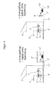
- KFZ-Stellplatz/Garage (Schalterstellung "Netz");
- Fig. 2:
- KFZ-Stellplatz/Garage (Schalterstellung "Außensteckdose");
- Fig. 3:
- KFZ-Stellplatz/Garage (Schalterstellung "Netz- und Generatortrennung"), Generator läuft und Einspeisung von EVU vorhanden;
- Fig. 4:
- KFZ-Stellplatz/Garage (Schalterstellung "Generator"), Betrieb über Notstromaggregat;
- Fig. 5:
- Normalbetrieb (Automaten und FI offen dargestellt) ;
- Fig. 6:
- Schalterstellung "Netz" / Normalbetrieb (Automaten und FI sind immer eingeschaltet);
- Fig. 7:
- Schalterstellung "Außensteckdose" / Normalbetrieb mit Außensteckdose;
- Fig. 8:
- Schalterstellung "Netz- und Generatortrennung" / Zwischenstellung (Netz und Generatortrennung); und
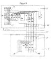
- Fig. 9:
- Schalterstellung "Generator" / Betrieb über Notstromaggregat.
- Fig. 1:
- Car parking space / garage (switch position "net");
- Fig. 2:
- Car parking space / garage (switch position "external socket");
- 3:
- Car parking space / garage (switch position "grid and generator disconnection"), generator runs and supply of EVU available;
- 4:
- Car parking space / garage (switch position "generator"), operation via emergency generator;
- Fig. 5:
- Normal operation (machines and FI open);
- Fig. 6:
- Switch position "mains" / normal operation (machines and FI are always switched on);
- Fig. 7:
- Switch position "external socket" / normal operation with external socket;
- Fig. 8:
- Switch position "Mains and generator disconnection" / intermediate position (mains and generator disconnection); and
- Fig. 9:
- Switch position "generator" / operation via emergency generator.
Die kompakte Einspeiseumschaltung ist so konzipiert, dass sie zum einen die Ein-speisung der Verbraucher in einem Haus durch einen Energieversorger (EVU) und zum anderen durch ein Notstromaggregat ermöglicht. Das komplette System besteht dabei aus einer Umschalteinrichtung (Inneneinheit) und einer Anschlusseinheit (Außeneinheit) und ist für einen Nennstrom von bis zu 63 A (nur Inneneinheit) ausgelegt. Die Umschalteinrichtung wird innerhalb der Kundenanlage zwischen dem Zähler und der Verteilung montiert. Zur Anschaltung eines Notstromaggregates oder zur alternativen Nutzung der Steckdose ist die vorgenannte Anschlusseinheit (Außeneinheit) erforderlich. Diese Außeneinheit ist mit einem 5-poligen CEE 16 A Kragenstecker sowie mit einer 5-poligen CEE 16 A Steckdose ausgestattet. Die Anschlusseinheit kann außerhalb des Gebäudes (Schutzklasse IP 44) montiert werden. Dabei ist eine Ausführung als Aufputz-Gehäuse (z.B. in einer Garage) oder als Standsäule (z.B. an einem KFZ-Stellplatz) möglich. In beiden Fällen werden die Umschalteinrichtung und die Anschlusseinheit über eine 7-polige Leitung miteinander verbunden.The compact feed switchover is designed in such a way that it enables the consumers to be fed into a house by an energy supplier (RU) and, secondly, by an emergency power generator. The complete system consists of a switching device (indoor unit) and a connection unit (outdoor unit) and is designed for a rated current of up to 63 A (indoor unit only). The changeover device is mounted within the customer plant between the meter and the distributor. To connect an emergency generator or alternative use of the socket, the aforementioned connection unit (outdoor unit) is required. This outdoor unit is equipped with a 5-pin CEE 16 A collar plug and a 5-pin CEE 16 A socket. The connection unit can be mounted outside the building (protection class IP 44). It is a version as a surface-mounted housing (eg in a garage) or as a pedestal (eg at a car parking space) possible. In both cases, the switching device and the connection unit are connected to each other via a 7-pin cable.
Die Umschalteinrichtung im Gebäude ist mit einem
- 3-poligen Leitungsschutzschalter (F1),
- einem 4-poligen Fehlerstromschutzschalter (FI1),
- einem 1- poligen Leitungsschutzschalter (F2),
- einem akustischen Signalgeber (H1), sowie
- einem Paketnockenschalter (S1)
mit 4 Schalterstellungen versehen.
- 3-pole circuit breaker (F1),
- a 4-pole residual current circuit breaker (FI1),
- a 1-pole circuit breaker (F2),
- an acoustic signal generator (H1), as well
- a package cam switch (S1) provided with 4 switch positions.
Die vier Schalterstellungen des Paketnockenschalters (S1) der Umschalteinrichtung bestimmen den Betriebszustand der kompakten Einspeiseumschaltung. Dabei stehen folgende Schalterstellungen zur Verfügung:
- 1. Schalterstellung "Netz"
- 2. Schalterstellung "Außensteckdose"
- 3. Schalterstellung "Netz und Generatortrennung" sowie
- 4. Schalterstellung "Generator"
- 1. switch position "net"
- 2. Switch position "external socket"
- 3. Switch position "Mains and generator disconnection" as well
- 4. switch position "generator"
Siehe dazu Zeichnung
In Schaltstellung "Netz" werden die Verbraucher durch den Energieversorger versorgt. Die zur Anschlusseinheit führende Leitung sowie die Anschlusseinheit selbst sind spannungslos. Diese Schalterstellung dient als Sicherheitsmaßnahme, um bei einer frei zugänglichen Außenaufstellung sicher zu stellen, dass die CEE-Steckdose nur bei Bedarf und nicht unbefugt genutzt wird.In switching position "grid", the consumers are supplied by the energy supplier. The line leading to the connection unit and the connection unit itself are de-energized. This switch position serves as a safety measure to ensure, in a freely accessible outdoor installation, that the CEE socket is used only when necessary and not without authorization.
Alle Automaten und Fehlerstromschutzschalter sind dabei eingeschaltet.All machines and residual current circuit breakers are switched on.
In der Schaltstellung "Außensteckdose" wird die Spannung bis zur Außeneinheit geschaltet. Die in der Anschlusseinheit enthaltene Anbausteckdose mit Schutzkappe 16 A wird direkt mit der Netzspannung versorgt. Der Leitungsschutzschalter (F1) erfüllt gemäß DIN VDE 0100 Teil 430 den Schutz gegen Überlast und Kurzschluss.
Der Fehlerstromschutzschalter (FI1) gewährleistet gemäß DIN VDE 0100 Teil 410 die Abschaltung für den Personenschutz.In the switch position "external socket", the voltage is switched to the outdoor unit. The attached socket in the connection unit with protective cap 16 A is supplied directly with the mains voltage. The miniature circuit breaker (F1) complies with DIN VDE 0100 part 430 for protection against overload and short circuit.
The fault current circuit breaker (FI1) ensures the shutdown for personal protection in accordance with DIN VDE 0100 Part 410.
Eine Zuschaltung des Not-Aus-Hauptschalters (S2) in der Außeneinheit (S2) und die damit verbundene Rückspeisung auf den Kragenstecker werden durch den Verriegelungskontakt und die fehlende Spannung für den Unterspannungsauslöser gewährleistet.A connection of the emergency stop main switch (S2) in the outdoor unit (S2) and the associated return to the collar connector are ensured by the locking contact and the lack of voltage for the undervoltage release.
In der Schalterstellung "Netz und Generatortrennung" sind die Verbraucher im Gebäude vom speisenden Netz des Energie-versorgers getrennt. Durch einen Verriegelungskontakt im Paketnockenschalter (S1) und der Verknüpfung mit dem Haupt-Not-Ausschalter (S2) in der Außeneinheit wird bei einspeisendem Notstromaggregat eine sichere Trennung von den Verbrauchern sowie vom Netz des Energieversorgers gewährleistet.In the switch position "grid and generator disconnection", the consumers in the building are disconnected from the supply network of the energy supplier. A locking contact in the package cam switch (S1) and the linkage to the main emergency off switch (S2) in the outdoor unit ensures a safe disconnection from the consumers as well as from the grid of the energy supplier when the emergency power unit is supplied.
In der Schalterstellung "Generator" werden im Paketnockenschalter (S1) zwei Steuerkontakte geschlossen. Ein Steuerkontakt (17/18) schaltet die vom Notstromaggregat erzeugte Spannung auf den Unterspannungsauslöser des Haupt-Not-Ausschalters (S2) in der Außeneinheit. Erst in dieser Stellung und bei gleichzeitigem Betrieb des Notstromaggregates kann der Haupt-Not-Ausschalter (S2) geschlossen werden. Nach Betätigung des Schalters werden die Verbraucher über das Notstromaggregat versorgt.In the "Generator" switch position, two control contacts are closed in the package cam switch (S1). A control contact (17/18) switches the voltage generated by the emergency generator to the undervoltage release of the main emergency stop switch (S2) in the outdoor unit. Only in this position and with simultaneous operation of the emergency power unit, the main emergency stop switch (S2) can be closed. After actuation of the switch, the consumers are supplied via the emergency generator.
Der Generator darf dabei eine Leistung von bis zu 11 kVA haben. Die maximal abnehmbare Leistung wird durch den Leitungsschutzschalter F1 abgesichert. Der CEE 16 A Kragenstecker der Außeneinheit und die 16 A Kupplung der Verlängerung zum Generator begrenzen ebenfalls die maximal zu übertragende Leistung.The generator may have a power of up to 11 kVA. The maximum removable power is protected by the circuit breaker F1. The CEE 16 A collar connector of the outdoor unit and the 16 A connector of the extension to the generator also limit the maximum power to be transmitted.
Bei Ausfall des Aggregates (Notstromgenerators) und der damit verbundenen Auslösung des Haupt-Not-Ausschalters (S2) erfolgt als Sicherheitsmaßnahme eine sofortige elektrische Trennung der Verbraucher vom Notstromaggregat.In case of failure of the unit (emergency generator) and the associated triggering of the main emergency stop switch (S2) takes place as a safety measure an immediate electrical separation of consumers from the emergency generator.
Über den zweiten Steuerkontakt (19/20) wird bei laufendem Notstromaggregat über den akustischen Signalgeber H1 signalisiert, wenn die Netzversorgung des Energie-versorgers wieder vorhanden ist. Die sichere Trennung in der Hausverteilung vom Netz des Energieversorgers bleibt auch in diesem Fall weiter gewährleistet.When the emergency generator is running, the second control contact (19/20) signals via the acoustic signal transmitter H1 if the power supply of the energy supplier is available again. The safe separation in the house distribution from the network of the energy supplier remains guaranteed in this case.
Nach Netzwiederkehr wird der Paketnockenschalter (S1) von Stellung "Generator" in Stellung "Netz und Generatortrennung" geschaltet. Durch diesen Zwischenschritt wird sichergestellt, dass zu keinem Zeitpunkt die Spannung vom EVU und vom Generator gleichzeitig zu den Verbrauchern geschaltet wird. Denn es erfolgt eine sofortige und sichere Trennung des Notstromaggregates von den Verbrauchern.After mains return the package cam switch (S1) is switched from position "Generator" to position "Mains and generator disconnection". This intermediate step ensures that at no time the voltage from the RU and the generator is switched to the consumers at the same time. Because there is an immediate and safe separation of the emergency generator from the consumer.
Nach dem Schalten auf "Netz" bzw. "Außensteckdose" wird die Versorgung der Verbraucher über das Netz des Energieversorgers wieder hergestellt.After switching to "mains" or "external socket", the power supply to the loads is restored via the utility's network.
Die Anschlusseinheit (als Aufputz-Gehäuse oder Standsäule) außerhalb des Gebäudes ist mit einem
- Not-Aus-Hauptschalter mit Unterspannungsauslöser (S2),
- einem 5-poligen CEE 16 A Kragenstecker sowie
- einer 5-poligen CEE 16 A Steckdose ausgestattet.
- Emergency stop main switch with undervoltage release (S2),
- a 5-pin CEE 16 A collar connector as well
- a 5-pin CEE 16 A socket equipped.
Die durch die Schalterstellungen des Paketnockenschalters (S1) der Umschalteinrichtung vorgegebenen Betriebszustände bestimmt die Art der Nutzung der Außeneinheit.The predetermined by the switch positions of the package cam switch (S1) of the switching operation states determines the type of use of the outdoor unit.
In Schaltstellung "Netz" ist die zur Anschlusseinheit führende Leitung spannungslos. Die Außeneinheit hat ebenfalls keine Spannung und damit keine Funktion.In switch position "Mains", the line leading to the connection unit is de-energized. The outdoor unit also has no voltage and thus no function.
In der Schaltstellung "Außensteckdose" wird die Spannung bis zur Außeneinheit geschaltet. Die in der Anschlusseinheit enthaltene Anbausteckdose mit Schutzkappe 16A wird direkt mit der Netzspannung versorgt.In the switch position "external socket", the voltage is switched to the outdoor unit. The attached socket in the connection unit with protective cap 16A is supplied directly with the mains voltage.
Eine Zuschaltung des Not-Aus-Hauptschalters (S2) in der Außeneinheit und die damit verbundene Rückspeisung auf den 5-poligen CEE 16 A Kragenstecker wird durch den Verriegelungskontakt und die fehlende Spannung für den Unterspannungsauslöser gewährleistet.A connection of the emergency stop main switch (S2) in the outdoor unit and the associated return to the 5-pole CEE 16 A collar plug is ensured by the locking contact and the lack of voltage for the undervoltage release.
In der Schalterstellung "Netz und Generatortrennung" ist die zur Anschlusseinheit führende Leitung spannungslos. Die Außeneinheit hat keine Funktion.In the switch position "Mains and generator disconnection", the line leading to the connection unit is de-energized. The outdoor unit has no function.
In der Stellung "Generator" werden im Paketnockenschalter (S1) der Umschalteinrichtung zwei Steuerkontakte geschlossen. Ein Steuerkontakt (17/18) schaltet die vom Notstromaggregat erzeugte Spannung auf den Unterspannungsauslöser des Haupt-Not-Ausschalters (S2) in der Außeneinheit. Erst in dieser Stellung und bei Betrieb des Notstromaggregates kann der Haupt-Not-Ausschalter (S2) geschlossen werden. Nach Betätigung des Schalters werden die Verbraucher über einen 5-poligen CEE 16 A Kragenstecker, an dem das Notstromaggregat angeschlossen ist, versorgt.In the "generator" position, two control contacts are closed in the package cam switch (S1) of the changeover device. A control contact (17/18) switches the voltage generated by the emergency generator to the undervoltage release of the main emergency stop switch (S2) in the outdoor unit. Only in this position and during operation of the emergency power unit, the main emergency stop switch (S2) can be closed. After pressing the switch, the consumers are supplied via a 5-pole CEE 16 A collar connector to which the emergency generator is connected.
Kabel zwischen Umschalteinrichtung (Inneneinheit) und Anschlusseinheit (Außeneinheit):Cable between switching device (indoor unit) and connection unit (outdoor unit):
Die Umschalteinrichtung und die Anschlusseinheit werden über eine 7-polige Leitung miteinander verbunden. Der erforderliche Querschnitt muss dabei den Verlegebedingungen und den gültigen DIN VDE-Anforderungen entsprechen.The switching device and the connection unit are connected to each other via a 7-pin cable. The required cross-section must comply with the laying conditions and the valid DIN VDE requirements.
- Haus 1'House 1 '
- Umschalteinrichtung (Inneneinheit) 2'Switching device (indoor unit) 2 '
- Verbraucher 3'Consumer 3 '
- Hausverteilung 4'House distribution 4 '
- Zähler 5'Counter 5 '
- Kabel von Energieversorger 6'Cable from utility company 6 '
- Anschluss (Außeneinheit) 7'Connection (outdoor unit) 7 '
- Energiesäule 8'Energy column 8 '
- Garage 9'Garage 9 '
- KFZ-Stellplatz 10'Car parking space 10 '
- Kabelverbindung zwischen Innen- und Außeneinheit (7'2,5qmm) 11'Cable connection between indoor and outdoor unit (7'2.5qmm) 11 '
- Elektro- oder Hybridfahrzeug 12'Electric or hybrid vehicle 12 '
- Notstromgenerator 13'Emergency power generator 13 '
- Klemmleiste 14'Terminal block 14 '
- Anbausteckdose mit Schutzkappe 16A 15'Extension socket with protective cap 16A 15 '
- Anbaugerätestecker mit Schutzkappe 16A 16'Attachment plug with protective cap 16A 16 '
Claims (7)
dadurch gekennzeichnet, dass
die Anschlusseinheit (7') eine mit dem Leitungselement (11') elektrisch verbundene Steckdose (15'), einen Stecker (16'), der zur elektrischen Verbindung eines Notstromgenerators (13') mit dem Leitungselement (11') ausgebildet ist, und einen Not-Aus-Hauptschalter (S2) mit einem Unterspannungsauslöser zur elektrischen Verbindung und Trennung des Steckers (16') von dem Leitungselement (11') aufweist, wobei der Unterspannungsauslöser zur Auslösung bei einer Unterspannung am Stecker (16') ausgebildet ist; und
die Umschalteinrichtung (2') zur elektrischen Trennung und Verbindung des Unterspannungsauslösers von dem Stecker (16'), zur elektrischen Trennung und Verbindung des Leitungselements (11') von dem Energieversorgernetzanschluss, und zur elektrischen Verbindung und Trennung des Steckers (16') von dem Leitungselement (11') ausgebildet ist.Feed switchover for switching between an energy supplier (6 ') and an emergency power generator (13') for an electrical distribution system (4 '), wherein the feed switchover a line element (11'), which is designed for electrical connection to an emergency generator (13 ') a switching device (2 ') which is electrically connected to the line element (11') and which has a power supply network connection, and a connection unit (7 '),
characterized in that
the connection unit (7 ') has a socket (15') which is electrically connected to the line element (11 '), a plug (16') which is designed to electrically connect an emergency power generator (13 ') to the line element (11'), and an emergency stop main switch (S2) having an undervoltage release for electrically connecting and disconnecting the plug (16 ') from the conduit member (11'), the undervoltage release being adapted to trip at an undervoltage on the plug (16 '); and
the switching device (2 ') for the electrical separation and connection of the undervoltage release of the plug (16'), for electrical separation and connection of the line member (11 ') from the power supply connection, and for the electrical connection and disconnection of the plug (16') of the Conduit element (11 ') is formed.
dadurch gekennzeichnet, dass
die Umschalteinrichtung (2') einen Paketnockenschalter (S1) mit mindestens vier Schalterstellungen aufweist, wobei
in einer ersten Schalterstellung ein Elektro-Hausverteilungsanschluss der Umschalteinrichtung (2') mit dem Energieversorgernetzanschluss verbunden ist und von dem Leitungselement (11') getrennt ist;
in einer zweiten Schalterstellung das Leitungselement (11') und der Elektro-Hausverteilungsanschluss mit dem Energieversorgernetzanschluss verbunden sind und von den Stecker (16') getrennt sind;
in einer dritten Schalterstellung der Elektro-Hausverteilungsanschluss von dem Energieversorgernetzanschluss getrennt ist und das Leitungselement (11') von dem Stecker (16') getrennt ist; und
in einer vierten Schalterstellung das Leitungselement (11') mit dem Elektro-Hausverteilungsanschluss verbunden ist und von dem Energieversorgernetzanschluss getrennt ist und der Unterspannungsauslöser mit dem Stecker (16') verbunden ist.Feed switchover according to claim 1,
characterized in that
the switching device (2 ') has a packet cam switch (S1) with at least four switch positions, wherein
in a first switch position, an electric home distribution connection of the switching device (2 ') is connected to the power supply network connection and is separated from the line element (11');
in a second switch position, the duct element (11 ') and the electrical domestic distribution terminal are connected to the power supply network terminal and are separated from the plugs (16');
in a third switch position, the power-house distribution terminal is disconnected from the power-supply terminal, and the wiring member (11 ') is disconnected from the plug (16'); and
in a fourth switch position, the duct element (11 ') is connected to the electrical domestic distribution terminal and is disconnected from the power supply network terminal and the undervoltage release is connected to the plug (16').
dadurch gekennzeichnet, dass
die Umschalteinrichtung (2') einen akustischen Signalgeber (H1) aufweist, der in der vierten Schalterstellung mit dem Energieversorgernetzanschluss verbunden ist.Feed switchover according to claim 2,
characterized in that
the switching device (2 ') has an acoustic signal transmitter (H1) which is connected in the fourth switch position to the power supply network connection.
dadurch gekennzeichnet, dass
der Paketnockenschalter (S1) aus der vierten Schalterstellung zur Schaltung in die dritte Schalterstellung ausgebildet ist und in die vierte Schalterstellung zur Schaltung aus der dritten Schalterstellung ausgebildet ist.Feed switchover according to one of claims 2 or 3,
characterized in that
the package cam switch (S1) is formed from the fourth switch position to the circuit in the third switch position and is formed in the fourth switch position for switching from the third switch position.
dadurch gekennzeichnet, dass
die Steckdose (15') als eine 5-polige 16-A-Steckdose ausgebildet ist und vorzugsweise eine Schutzkappe aufweist.Feed switching according to one of claims 1 to 4,
characterized in that
the socket (15 ') is designed as a 5-pin 16 A socket and preferably has a protective cap.
dadurch gekennzeichnet, dass
der Stecker (16') als ein 5-poliger 16-A-Stecker, vorzugsweise als ein Kragenstecker mit Schutzkappe, ausgebildet ist.Feed switching according to one of claims 1 to 5,
characterized in that
the plug (16 ') is designed as a 5-pin 16 A plug, preferably as a collar plug with protective cap.
dadurch gekennzeichnet, dass
das elektrische Leitungselement (11') ein 7-poliges Kabel aufweist und die Anschlusseinheit (7') vorzugsweise als ein Aufputz-Gehäuse oder eine Standsäule (8') ausgebildet ist.Feed switching according to one of the preceding claims,
characterized in that
the electrical line element (11 ') has a 7-pole cable and the connection unit (7') is preferably designed as a surface-mounted housing or a pedestal column (8 ').
Priority Applications (1)
| Application Number | Priority Date | Filing Date | Title |
|---|---|---|---|
| EP15163661.0A EP3082218A1 (en) | 2015-04-15 | 2015-04-15 | Compact feed-in switching between an energy supplier and an emergency power generator for an electric house distribution system |
Applications Claiming Priority (1)
| Application Number | Priority Date | Filing Date | Title |
|---|---|---|---|
| EP15163661.0A EP3082218A1 (en) | 2015-04-15 | 2015-04-15 | Compact feed-in switching between an energy supplier and an emergency power generator for an electric house distribution system |
Publications (1)
| Publication Number | Publication Date |
|---|---|
| EP3082218A1 true EP3082218A1 (en) | 2016-10-19 |
Family
ID=52997872
Family Applications (1)
| Application Number | Title | Priority Date | Filing Date |
|---|---|---|---|
| EP15163661.0A Withdrawn EP3082218A1 (en) | 2015-04-15 | 2015-04-15 | Compact feed-in switching between an energy supplier and an emergency power generator for an electric house distribution system |
Country Status (1)
| Country | Link |
|---|---|
| EP (1) | EP3082218A1 (en) |
Cited By (1)
| Publication number | Priority date | Publication date | Assignee | Title |
|---|---|---|---|---|
| FR3114056A1 (en) * | 2020-09-14 | 2022-03-18 | Renault | Electric vehicle and switching device for a household electrical network |
Citations (5)
| Publication number | Priority date | Publication date | Assignee | Title |
|---|---|---|---|---|
| US3025408A (en) * | 1958-09-23 | 1962-03-13 | George D Wolf | Emergency power supply |
| DE3000253A1 (en) * | 1980-01-05 | 1981-07-09 | Brinkmann, Julius, 2000 Hamburg | Switching unit for auxiliary power supplies - has connections and oppositely acting switches for mains and stand by supplies and overload switch |
| JP2010172068A (en) * | 2009-01-20 | 2010-08-05 | Chugoku Electric Power Co Inc:The | Electrical outlet system |
| DE102009022363A1 (en) * | 2009-04-16 | 2010-10-21 | Andreas Burmeister | Electric plug socket for music equipment, has earth pole and signal pole, where earth pole has conductive material and signal pole has another conductive material |
| CN103647338A (en) * | 2013-12-02 | 2014-03-19 | 国家电网公司 | Emergency power guaranteeing system and emergency power supply method using same |
-
2015
- 2015-04-15 EP EP15163661.0A patent/EP3082218A1/en not_active Withdrawn
Patent Citations (5)
| Publication number | Priority date | Publication date | Assignee | Title |
|---|---|---|---|---|
| US3025408A (en) * | 1958-09-23 | 1962-03-13 | George D Wolf | Emergency power supply |
| DE3000253A1 (en) * | 1980-01-05 | 1981-07-09 | Brinkmann, Julius, 2000 Hamburg | Switching unit for auxiliary power supplies - has connections and oppositely acting switches for mains and stand by supplies and overload switch |
| JP2010172068A (en) * | 2009-01-20 | 2010-08-05 | Chugoku Electric Power Co Inc:The | Electrical outlet system |
| DE102009022363A1 (en) * | 2009-04-16 | 2010-10-21 | Andreas Burmeister | Electric plug socket for music equipment, has earth pole and signal pole, where earth pole has conductive material and signal pole has another conductive material |
| CN103647338A (en) * | 2013-12-02 | 2014-03-19 | 国家电网公司 | Emergency power guaranteeing system and emergency power supply method using same |
Cited By (1)
| Publication number | Priority date | Publication date | Assignee | Title |
|---|---|---|---|---|
| FR3114056A1 (en) * | 2020-09-14 | 2022-03-18 | Renault | Electric vehicle and switching device for a household electrical network |
Similar Documents
| Publication | Publication Date | Title |
|---|---|---|
| US10535982B2 (en) | Meter socket adapter with integral automatic transfer switch | |
| DE69935650T2 (en) | Power distribution system with signals transmitted through power lines, remote resettable circuit breakers | |
| EP2256822A2 (en) | Safety switching assembly for solar assemblies | |
| DE102017209128B4 (en) | Method for operating a vehicle charging device, vehicle charging device and system comprising a sensor device and a vehicle charging device | |
| WO2014140004A2 (en) | Charging device for an electric vehicle | |
| RU2496199C2 (en) | Complete high-voltage switchgear | |
| DE102010014548A1 (en) | Eletkische low-voltage building installation | |
| CN201490118U (en) | Electric-shock protection structure for residual current circuit breakers and moulded case circuit breakers | |
| AU2018357310B2 (en) | Locking device for circuit breaker operation device | |
| WO2015059195A1 (en) | Inverter system and pv system | |
| CN103794390B (en) | A kind of high voltage switchgear has the mechanical interlocks of double-direction control function | |
| CN106300104B (en) | Universal attachment device and its application of the power supply vehicle of meet an emergency with low pressure aerial condutor | |
| US9118139B1 (en) | Flip lid interlock | |
| DE102013106216A1 (en) | Measuring device for current measurement | |
| EP3082218A1 (en) | Compact feed-in switching between an energy supplier and an emergency power generator for an electric house distribution system | |
| DE102017011373A1 (en) | Measuring and control electronics for low-voltage switchgear | |
| CN107968329A (en) | Grid-connected access case and its access system | |
| DE102013020858B3 (en) | Compact feed-in switching between energy supplier and an emergency generator for an electrical home distribution | |
| CN110416894A (en) | Outdoor mobile exchange emergency power distribution equipment | |
| CN205303956U (en) | Automatic switching compensation cabinet mounting structure divides into groups | |
| EP2500208A2 (en) | Protective circuit assembly | |
| CN208489574U (en) | A kind of low-voltage comprehensive distribution box with emergency power supply plug | |
| CN204258420U (en) | Moving lifting voltage source car | |
| US20100330826A1 (en) | Speed Wire Device | |
| CN201490818U (en) | Low-voltage motor equipment |
Legal Events
| Date | Code | Title | Description |
|---|---|---|---|
| PUAI | Public reference made under article 153(3) epc to a published international application that has entered the european phase |
Free format text: ORIGINAL CODE: 0009012 |
|
| AK | Designated contracting states |
Kind code of ref document: A1 Designated state(s): AL AT BE BG CH CY CZ DE DK EE ES FI FR GB GR HR HU IE IS IT LI LT LU LV MC MK MT NL NO PL PT RO RS SE SI SK SM TR |
|
| AX | Request for extension of the european patent |
Extension state: BA ME |
|
| RIN1 | Information on inventor provided before grant (corrected) |
Inventor name: CLASEN, KLAUS Inventor name: DITTRICH, JENS Inventor name: PED, TORSTEN |
|
| STAA | Information on the status of an ep patent application or granted ep patent |
Free format text: STATUS: THE APPLICATION IS DEEMED TO BE WITHDRAWN |
|
| 18D | Application deemed to be withdrawn |
Effective date: 20170420 |