EP3082002B1 - Sicherheitssteuerung und verfahren zum steuern einer automatisierten anlage - Google Patents
Sicherheitssteuerung und verfahren zum steuern einer automatisierten anlage Download PDFInfo
- Publication number
- EP3082002B1 EP3082002B1 EP16169017.7A EP16169017A EP3082002B1 EP 3082002 B1 EP3082002 B1 EP 3082002B1 EP 16169017 A EP16169017 A EP 16169017A EP 3082002 B1 EP3082002 B1 EP 3082002B1
- Authority
- EP
- European Patent Office
- Prior art keywords
- data
- project data
- project
- safety
- memory
- Prior art date
- Legal status (The legal status is an assumption and is not a legal conclusion. Google has not performed a legal analysis and makes no representation as to the accuracy of the status listed.)
- Active
Links
- 238000000034 method Methods 0.000 title claims description 39
- 230000015654 memory Effects 0.000 claims description 193
- 238000012545 processing Methods 0.000 claims description 83
- 238000009826 distribution Methods 0.000 claims description 45
- 230000006870 function Effects 0.000 claims description 38
- 238000004590 computer program Methods 0.000 claims description 4
- 238000009434 installation Methods 0.000 claims 4
- 238000003860 storage Methods 0.000 description 21
- 230000008569 process Effects 0.000 description 18
- 230000008901 benefit Effects 0.000 description 10
- 238000013459 approach Methods 0.000 description 9
- 230000004044 response Effects 0.000 description 8
- 230000000694 effects Effects 0.000 description 7
- 230000001681 protective effect Effects 0.000 description 5
- 238000012546 transfer Methods 0.000 description 5
- 238000013507 mapping Methods 0.000 description 4
- 238000012360 testing method Methods 0.000 description 4
- 230000005540 biological transmission Effects 0.000 description 3
- 230000002950 deficient Effects 0.000 description 3
- 230000009467 reduction Effects 0.000 description 3
- 230000009471 action Effects 0.000 description 2
- 230000008859 change Effects 0.000 description 2
- 238000006243 chemical reaction Methods 0.000 description 2
- 238000013500 data storage Methods 0.000 description 2
- 230000006735 deficit Effects 0.000 description 2
- 230000007257 malfunction Effects 0.000 description 2
- 238000004806 packaging method and process Methods 0.000 description 2
- 238000004886 process control Methods 0.000 description 2
- 230000001360 synchronised effect Effects 0.000 description 2
- 238000013475 authorization Methods 0.000 description 1
- 238000007630 basic procedure Methods 0.000 description 1
- 230000007175 bidirectional communication Effects 0.000 description 1
- 230000006854 communication Effects 0.000 description 1
- 238000004891 communication Methods 0.000 description 1
- 238000001816 cooling Methods 0.000 description 1
- 238000013523 data management Methods 0.000 description 1
- 238000011161 development Methods 0.000 description 1
- 238000003745 diagnosis Methods 0.000 description 1
- 231100001261 hazardous Toxicity 0.000 description 1
- 238000003754 machining Methods 0.000 description 1
- 238000012423 maintenance Methods 0.000 description 1
- 238000004519 manufacturing process Methods 0.000 description 1
- 238000012806 monitoring device Methods 0.000 description 1
- 238000012544 monitoring process Methods 0.000 description 1
- 238000005457 optimization Methods 0.000 description 1
- 238000013439 planning Methods 0.000 description 1
- 230000035484 reaction time Effects 0.000 description 1
- 230000009897 systematic effect Effects 0.000 description 1
- 230000007704 transition Effects 0.000 description 1
- 238000012800 visualization Methods 0.000 description 1
Images


Classifications
-
- G—PHYSICS
- G05—CONTROLLING; REGULATING
- G05B—CONTROL OR REGULATING SYSTEMS IN GENERAL; FUNCTIONAL ELEMENTS OF SUCH SYSTEMS; MONITORING OR TESTING ARRANGEMENTS FOR SUCH SYSTEMS OR ELEMENTS
- G05B19/00—Programme-control systems
- G05B19/02—Programme-control systems electric
- G05B19/418—Total factory control, i.e. centrally controlling a plurality of machines, e.g. direct or distributed numerical control [DNC], flexible manufacturing systems [FMS], integrated manufacturing systems [IMS] or computer integrated manufacturing [CIM]
- G05B19/41865—Total factory control, i.e. centrally controlling a plurality of machines, e.g. direct or distributed numerical control [DNC], flexible manufacturing systems [FMS], integrated manufacturing systems [IMS] or computer integrated manufacturing [CIM] characterised by job scheduling, process planning, material flow
-
- G—PHYSICS
- G05—CONTROLLING; REGULATING
- G05B—CONTROL OR REGULATING SYSTEMS IN GENERAL; FUNCTIONAL ELEMENTS OF SUCH SYSTEMS; MONITORING OR TESTING ARRANGEMENTS FOR SUCH SYSTEMS OR ELEMENTS
- G05B2219/00—Program-control systems
- G05B2219/30—Nc systems
- G05B2219/32—Operator till task planning
- G05B2219/32283—Machine scheduling, several machines, several jobs
-
- G—PHYSICS
- G05—CONTROLLING; REGULATING
- G05B—CONTROL OR REGULATING SYSTEMS IN GENERAL; FUNCTIONAL ELEMENTS OF SUCH SYSTEMS; MONITORING OR TESTING ARRANGEMENTS FOR SUCH SYSTEMS OR ELEMENTS
- G05B2219/00—Program-control systems
- G05B2219/30—Nc systems
- G05B2219/33—Director till display
- G05B2219/33273—DCS distributed, decentralised controlsystem, multiprocessor
-
- G—PHYSICS
- G05—CONTROLLING; REGULATING
- G05B—CONTROL OR REGULATING SYSTEMS IN GENERAL; FUNCTIONAL ELEMENTS OF SUCH SYSTEMS; MONITORING OR TESTING ARRANGEMENTS FOR SUCH SYSTEMS OR ELEMENTS
- G05B2219/00—Program-control systems
- G05B2219/30—Nc systems
- G05B2219/33—Director till display
- G05B2219/33338—DNC distributed, decentralised nc, concurrent, multiprocessing
-
- Y—GENERAL TAGGING OF NEW TECHNOLOGICAL DEVELOPMENTS; GENERAL TAGGING OF CROSS-SECTIONAL TECHNOLOGIES SPANNING OVER SEVERAL SECTIONS OF THE IPC; TECHNICAL SUBJECTS COVERED BY FORMER USPC CROSS-REFERENCE ART COLLECTIONS [XRACs] AND DIGESTS
- Y02—TECHNOLOGIES OR APPLICATIONS FOR MITIGATION OR ADAPTATION AGAINST CLIMATE CHANGE
- Y02P—CLIMATE CHANGE MITIGATION TECHNOLOGIES IN THE PRODUCTION OR PROCESSING OF GOODS
- Y02P90/00—Enabling technologies with a potential contribution to greenhouse gas [GHG] emissions mitigation
- Y02P90/02—Total factory control, e.g. smart factories, flexible manufacturing systems [FMS] or integrated manufacturing systems [IMS]
Definitions
- the present invention relates to a safety controller and a method for controlling an automated system as a function of project data according to the preambles of claims 1 and 11, the project data representing an application running on the system.
- a safety controller in the sense of the present invention is a device or a device that receives input signals supplied by sensors and generates output signals therefrom by means of logic operations and possibly further signal or data processing steps. The output signals can then be fed to actuators which, depending on the input signals, cause actions or reactions in a controlled system.
- a preferred area of application for such safety controls is the monitoring of emergency stop buttons, two-hand controls, protective doors or light grids in the field of machine safety.
- sensors are used, for example, to secure a machine that poses a risk to people or material goods during operation.
- a signal is generated that is fed to the safety control as an input signal.
- the safety control then switches off the dangerous part of the machine, for example with the help of an actuator.
- a characteristic of a safety controller in contrast to a "normal" controller, is that the safety controller always guarantees a safe state of the hazardous systems or machines even if a malfunction occurs with it or one of the devices connected to it. For this reason, extremely high demands are placed on safety controls for their own fault tolerance, which results in considerable effort in development and manufacture.
- a safety controller is understood to mean a device or a device that meets at least safety category 3 of the mentioned European standard EN 954-1 or whose Safety Integrity Level (SIL) reaches at least level 2 according to the mentioned standard IEC 61508.
- SIL Safety Integrity Level
- a programmable safety control offers the user the possibility of individually defining the logical links and, if necessary, further signal or data processing steps with the help of software, the so-called user program, according to his needs. This results in a Great flexibility compared to previous solutions in which the logical links were created through defined wiring between different safety modules.
- a user program can be created, for example, with the aid of a commercially available personal computer (PC) and using appropriately set up software programs.
- PC personal computer
- the term user program is understood to mean that a user program includes both source code and machine code.
- distributed safety controls In the case of large and thus complex systems according to the state of the art, which are built up from a large number of system hardware components, distributed safety controls are usually used.
- Distributed safety controls consist of a large number of control hardware components. These are control units, sensors and actuators.
- the individual control hardware components are assigned to individual system hardware components.
- distributed safety controls are characterized by great flexibility.
- a safety controller can be built from any number of different control hardware components and can therefore be adapted very flexibly to the conditions of the system to be controlled.
- distributed safety controls are not yet optimal. There is no provision for distributing project data, that is, data that represent an application running on the controlled system, to the individual control hardware components.
- On site in this context means that the project data is processed where the data required for its processing is available. For example, in a control unit that is located in the immediate vicinity of a sensor, whose sensor signal is required as an input signal for determining a control signal for an actuator. Or processing even takes place in the sensor itself.
- US 6,170,044 B1 discloses a system and a method according to the preambles of claims 1 and 11.
- the system includes a plurality of process controls, each of which controls a sub-process in a plant.
- a higher-level controller communicates with the process controllers and generates higher-level data in order to optimize the process flow in the plant.
- At least some of the process controls are redundant, with a first processor module controlling a partial process, while a second processor module remains passive until the first processor module fails and its control tasks are taken over by the second processor module.
- process data in the memory of the second processor module are continuously synchronized with the process data in the memory of the first processor module.
- U.S. 5,699,242 discloses a control system for a factory plant with a plurality of control devices. So-called end control devices, for example in the form of programmable logic controllers (PLC), control individual sub-processes. Groups of end control devices are coordinated by higher-level controls. Several end control devices can use a common memory area in order to carry out functionally identical tasks.
- PLC programmable logic controller
- EP 1 231 526 A1 discloses a control system with a plurality of networked controllers.
- a so-called connection memory stores process data in the Network to be shared.
- the individual controls use uniform variable names to access this shared data.
- the new safety control and the new method are based on the idea of providing a distribution unit in a safety control that is designed to distribute at least part of the project data to data memories contained in control hardware components and thus the distribution of project data to control hardware components that make up the safety control is to enable.
- project data can be specifically saved in individual data memories that are contained in various control hardware components.
- This also enables project data to be saved in so-called intelligent input / output units.
- sensors and actuators that have data processing units, for example microprocessors, and data memories.
- data memories available in a safety controller which would otherwise largely remain unused, can be filled with project data and thus used.
- control units that are present in a safety controller can be equipped with smaller data memories in the future. This reduces the costs for a safety controller.
- the response time of a safety controller is reduced. Project data can be saved there and are therefore available where, for example, required sensor signals are present or control signals for actuators are to be provided. This reduces the data exchange, which ultimately leads to a reduction in the response time. The reduction in data exchange also leads to an increase the availability of the safety controller. Since there is less data to be exchanged, there are also fewer data transmission errors.
- Distributing and thus saving project data in several project data memories also has advantages with regard to the implementation and handling of a safety controller. If, for example, after planning a safety controller in trial operation, it is found that the memory capacity available in the safety controller and formed by all data memories is too small, this can be increased by adding an additional control hardware component that has a data memory. The project data can then be redistributed to the previous and additional data memories. The safety controller can therefore be scaled as required.
- the project data required for the new control hardware component can be provided in a simple manner if a device replacement is necessary. All that is required is to remove the memory card from the defective control hardware component to be removed and insert it into the new control hardware component to be inserted.
- address data, configuration data and program data can be made available without a notebook having to be connected to the new control hardware component for this purpose.
- the project data include program data and / or configuration data and / or parameterization data.
- the program data represent the user program and are generated when the user program is created.
- the configuration data represent individual aspects of the data transmission. This involves, for example, a cycle time, link data that determine which of the control hardware components are connected to one another, or data that represent which sensors or actuators, which inputs or outputs of individual control units are assigned, or to data that determine the type of data to be exchanged between individual control hardware components, for example. It is therefore data that represent the configuration of the safety control that is implemented in a distributed manner.
- the configuration data can be generated when creating the user program. However, they can also be created or changed to a certain extent after the user program has been created.
- the parameterization data represent value ranges for individual variables or functionalities used in the user program.
- At least some of the control hardware components contain a data processing unit, project data specific to the respective data processing unit being stored in that project data memory that is contained in that control hardware component in which the data processing unit is contained.
- a data processing unit can be a unit to which data is supplied as input data for an operation and which outputs output data determined as a result of this operation as a function of the input data.
- a data processing unit can, however, also be understood to mean a unit to which data is supplied in order to pass it on to another unit.
- Safety controls contain data processing units in the most varied of configurations. For example, data-based message switching units are used. For example, these make data generated by their own control unit available to other control units and read data generated by other control units, which are required in the own control unit for further processing. Such data processing units are known as data brokers.
- Event-based message switching units can also be involved. Such message switching units send a signal when a defined condition is met in their own control unit in order to trigger a defined reaction in another control unit or in the system to be controlled. Such message switching units also receive such signals in a corresponding manner. Such message switching units are known as event brokers. In addition, connection units are also used that are required to enable data exchange between individual control hardware components at all. Such data processing units are referred to as data bus interfaces. In addition, a project data memory is also a data processing unit, since the project data memory can not only store project data but also request and forward project data. Depending on how the data processing unit is designed, the respective project data stored for the data processing unit differ.
- an event broker or a data bus interface for example, configuration data and parameterization data are stored.
- project data are also stored for a project data memory, preferably those project data that are processed in the control unit in which the project data memory is contained.
- At least one of the project data memories is designed to forward project data supplied to it to at least one other project data memory or to request project data stored in another project data memory.
- a project data memory which is designed to store, forward and request project data, can also be referred to as a project data server, or project server for short, due to this range of functions.
- the distribution unit is one of the project data memories.
- This measure has the advantage that no additional unit needs to be provided in the safety controller for distributing the project data.
- the project data is distributed from one of the project data memories already present in the safety controller. This enables a cost-effective implementation of the safety control.
- Another advantage is that functionalities that are present in a project data memory and that have been optimized with regard to the processing of project data can be used for distributing the project data.
- the interface of a project data memory is given as an example.
- the project data memory that is used as a distribution unit has the function of a master when distributing the project data.
- the remaining project data memories each take on the function of a slave.
- the project data memory that is used as a distribution unit advantageously has a greater storage capacity than would be required for the operation of that control hardware component in which it is arranged. For the following reason: When the project data is distributed, data is generated that is required for later operation of the safety controller. These can thus be cached in the aforementioned project data memory.
- the project data are usually created using a programming tool that runs on a programming unit. This is usually a structurally separate unit from the safety controller.
- the programming unit comprises, for example, a computer designed as a personal computer.
- the programming unit can be connected via a cable to that control hardware component in which the project data memory is contained, or even to the project data memory itself. This configuration is particularly suitable when the complete project data is to be imported into the safety controller in a single process.
- the project data can be transferred to the project data memory using a mobile storage medium.
- memory cards which can be designed as SD cards (Secure Digital Memory Cards) or CF cards (Compact Flash Cards), or a USB stick (Universal Serial Bus) can be used.
- SD cards Secure Digital Memory Cards
- CF cards Compact Flash Cards
- USB stick Universal Serial Bus
- a conscious user action is advantageously to be carried out for the initialization of the distribution process.
- a specific key combination has to be pressed or a button has to be pressed or a defined input has to be made via a graphic surface.
- the distribution process is advantageously initialized automatically by the programming unit.
- a mobile storage medium has various advantages. It is thus possible to only upload project data to selected control hardware components by specifically connecting the mobile storage medium to these control hardware components. Another advantage is that the mobile storage medium can also be used for backup purposes.
- the machine code stored in a safety controller can be stored on the mobile storage medium and read into the safety controller again if necessary.
- the distribution unit is an external distribution unit which is connected at least temporarily to an interface provided for this purpose in the safety controller.
- the external distribution unit is located in the programming unit on which the programming tool that is used to create the project data runs. This allows the project data to be transferred directly from the programming unit to the safety controller. On the one hand, this is not very complex. On the other hand, this increases the fail-safe safety of the safety controller, since potential sources of error with regard to the transfer of the project data are excluded.
- a further advantage of this embodiment is that after the project data has been completed in a so-called trial operation, in which the functionality of the safety controller and the system to be controlled is tested and in which it is determined that changes to the project data are to be made, these in can be updated easily.
- the project data is transferred from the programming unit to the safety controller, for example, using a cable.
- the programming unit is not permanently connected to the safety controller, but only temporarily. For example, for the period of programming, i.e. for the period in which the project data is generated. Or even only for the period during which the project data is being transferred from the programming unit to the safety controller.
- the programming unit can be understood as part of the safety control, since the project data, in particular the user program for the system to be controlled, are generated with the programming unit.
- control hardware components are control units and / or sensors and / or actuators.
- control units can be used as project data memories, but also the memories present in so-called intelligent sensors and intelligent actuators.
- This enables a particularly flexible distribution of the project data, in particular to the effect that partial processing of the project data can take place directly on site. This helps to improve the response time of the safety controller.
- the project data are divided into a multiplicity of data packets, the individual data packets each being assigned to at least one of the project data memories.
- This measure has the advantage that the project data can be specifically assigned to individual project data memories in accordance with a specific distribution criterion. In this way, a safety controller can be optimized with regard to different parameters by appropriate selection of the distribution criterion.
- a programming unit for creating the project data, the programming unit being designed to generate assignment data, the distribution unit also being designed to distribute the project data to the project data memory as a function of the assignment data.
- the project data can be distributed to the individual project data memories according to a freely definable distribution criterion. At the same time, an error-free and, if necessary, as often reproducible distribution of the project data is guaranteed.
- the assignment data can have the character of a proposal and represent a list of preferences which, for example, the creator of the project data or the operator of the system to be controlled can change. On the other hand, it can also be provided that the assignment data cannot be changed, so that in this case the project data is distributed completely automatically.
- the assignment data can contain, for example, the following information: For each project data memory contained in the safety controller, the data packets to be saved on this or the data packets then saved on it are listed. It is therefore clear which data packet belongs to which control hardware component or which data processing unit.
- the assignment data can also determine the order of the project data memories in which they are used when distributing the Project data are taken into account. Such an order provides that the project data memory that is used as the distribution unit is always taken into account first.
- the assignment data can contain information about which data packets are to be stored in the respective project data memory or are then stored there.
- information can be provided for each control hardware component which specifies the project data memories on which the project data of the respective control hardware component are located.
- each control hardware component or each data processing unit can call up the project data provided for them from the corresponding project data memories in which they are stored. It is also conceivable to only generate part of the assignment data during the distribution process itself. This is useful, for example, for the data, specifying the project data memories on which the project data of the respective control hardware components are located.
- the programming unit is designed to determine the assignment data as a function of at least one data processing parameter.
- the data processing parameter represents a parameter relevant for data processing of a component used in data processing. This can be, for example, the clock frequency of a microprocessor, the data rates of a data broker or an event broker or a data bus interface or the storage capacity of a project data memory. If data processing parameters of the control hardware components or individual units built into them are taken into account when determining the assignment data, then the project data can be distributed from the point of view of optimized data processing. For example, project data that requires high computing power to process can be stored in control hardware components that are equipped with a powerful microprocessor. In addition, depending on their size, data packets can be based on those in the safety controller Data storage are distributed. For example, small data packets can be stored in a targeted manner in data memories with a small storage capacity. This measure is particularly advantageous for a completely automatic distribution of the project data to the project data memory.
- the programming unit is designed to determine the assignment data as a function of at least one function assignment variable.
- the function allocation variable represents for an individual data packet or a group of data packets that project data memory in which this data packet or this group is to be stored.
- the project data memory is defined in that the storage is to take place in that project data memory which is located in that control hardware component, in particular that control unit, in which the project data are processed.
- the function assignment variables are advantageously specified by the programmer of a user program in that he stipulates which scopes of the user program should run on soft control hardware components, for example control units.
- At least part of the project data is stored redundantly in the project data memory.
- the redundant storage of the data packets is achieved by duplicating the respective data packets.
- the duplicated data packets are then distributed independently to the project data memories, with the proviso that the original and the duplicated data packets are each in a different project data memory get saved.
- This measure has the advantage that the availability of the safety control and thus of the controlled system is increased. If, for example, a non-safety-relevant control hardware component fails, the project data that were stored in your project data memory are still available because they are still available in another project data memory. This also makes it easier to replace a defective control hardware component. All you have to do is replace the defective component with a new component.
- the project data required for the new component can, for example, be automatically requested from the respective project data memories on which they are still stored and stored in the project data memory of the new component.
- the redundant storage of the project data also enables individual control tasks to be carried out in parallel.
- At least some of the project data memories are designed to store the project data supplied in each case in a non-volatile manner.
- This measure has the advantage that the project data is still available, for example after a power failure or after the safety controller has been switched off. This increases the availability of the safety controller.
- the safety controller does not need to be re-initialized. For example, memory cards in the form of SD cards or CF cards are used for this, or flash memories are used.
- the progress of the distribution process can preferably be displayed by graphic means during the distribution of the project data to the individual project data stores. In this way, for example, an operator of the system to be controlled can easily find out about the status of the distribution process.
- Each control hardware component preferably contains a project data memory. This enables an optimal distribution of the project data.
- the project data is available wherever it is needed.
- the application running on the system to be controlled can also be referred to as a process, which includes both standard control tasks and safety control tasks.
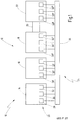
- a system to be controlled is designated in its entirety with the reference number 10.
- the system 10 consists of a large number of system hardware components 12.
- a loading station 14 a processing station 16, a test station 18, a conveyor unit 20 and a packaging and palletizing station 22.
- a safety controller in its entirety denoted by the reference number 24.
- the safety controller 24 contains a large number of control hardware components 26.
- the control hardware components 26 are control units 28, sensors 30 and actuators 32.
- the individual control units 28, sensors 30 and individual actuators 32 are each assigned to one of the system hardware components 12 and are spatially arranged there .
- the control hardware components 12 are connected to one another via a connection unit 34.
- the connection unit 34 is a data bus which is designed, for example, as an Ethernet-based field bus.
- a data bus system is preferably used, which works according to the SafetyNET p ® communication model, which can be traced back to the applicant.
- the processing station 16 With the loading station 14, the processing station 16 is filled with workpieces. These workpieces are processed in the processing station 16. The machined workpieces are then passed on from the machining station 16 to the test station 18, in which it is checked whether the machined workpiece meets the corresponding test criteria. If these test criteria are met, the processing station 16 can be filled again with a new workpiece. The processed workpiece is transferred to the packaging and palletizing station 22 by means of the conveyor unit 20. In this, several processed workpieces are combined into bundles, which are then stacked on a pallet.
- the working areas of the individual stations 14, 16, 18, 22 can be secured, for example, by protective doors that are equipped with safety switches, by means of which a tumbler with locking can be implemented. Alternatively or in addition, light grids or light curtains can also be used.
- the individual stations 14, 16, 18, 22 can be provided with emergency stop buttons with which the respective station can be switched to a safe state by disconnecting it from the power supply. Contactors are controlled accordingly for this.
- the aforementioned protective doors, light grids, light curtains and emergency stop buttons are safety-relevant sensors that are contained in the sensors 30.
- the contactors are safety-relevant actuators that are contained in the actuators 32.
- the sensors 30 can furthermore comprise non-safety-relevant sensors. These are sensors that record operating variables, for example input variables required for drive or position control, such as rotational speeds, angles or speeds.
- the actuators 32 can also include actuators that are not relevant to safety. These can be motors or actuating cylinders, for example.
- a control unit 28 is assigned to each station 14, 16, 18, 22.
- the control units 28 are structurally independent Components trained. This also applies to the sensors 30 and the actuators 32. However, this is not intended to have a restrictive effect. It is also conceivable, for example, to assign a common control unit to two stations.
- the individual system hardware components can be structurally and spatially separated from one another. However, it is also conceivable that some of these components are operatively connected to one another.
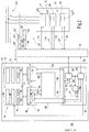
- Fig. 2 the processing station 16 and the control hardware components assigned to it are shown in a more detailed representation. These are the control unit 28 ', the sensors 30' and the actuators 32 ', which are connected to one another by the connection unit 34.
- the control unit 28 ' has a two-channel redundant structure in order to achieve the necessary fail-safe security for controlling safety-critical applications or processes. Representing the two-channel structure are in Fig. 2 two separate processors, namely a first processor 40 and a second processor 42, shown.
- the two processors 40, 42 are connected to one another via a bidirectional communication interface 44 in order to be able to monitor one another and exchange data.
- the two channels of the control unit 28 'and the two processors 40, 42 are preferably constructed diversely, ie different from one another, in order to largely rule out systematic errors.
- Reference numeral 46 denotes an input / output unit which is connected to each of the two processors 40, 42.
- the input / output unit 46 takes Control input signals 48 from the sensors 30 ′ and forwards them in an adapted data format to each of the two processors 40, 42.
- the input / output unit 46 generates control output signals 50 as a function of the processors 40, 42, with which the actuators 32 ′ are controlled.
- the reference number 52 denotes a project data memory in which project data 54 are stored in the form of data packets.
- This is a first data packet 56 which contains first configuration data 58 for a data broker 60.
- the project data memory 52 contains a second data packet 62 with second configuration data 64 for an event broker 66.
- the project data memory 52 contains a third data packet 68 with third configuration data 70 for a data bus interface 72 contains itself.
- the project data memory 52 contains a fifth data packet 76 and a sixth data packet 78.
- These two data packets contain program data which represent the scope of a user program that is processed in the control unit 28 '.
- the project data memory 52 also contains a seventh data packet 80 which contains parameterization data. These parameterization data are required, for example, when processing the project data and define, for example, value ranges for variables or functionalities.
- the actuators 32 'and the sensors 30' are also equipped with project data memories 52 ', 52 ", 52"', 52 "”. This is not intended to have a restrictive effect. Not all control hardware components need to have project data memories. that only project data 54, which are processed in units contained in the control unit 28 ', are stored in the project data memory 52. Project data 54 that are required or processed in another control hardware component can also be stored in the project data memory 52 Data packets from units that are contained in the control unit 28 'are also stored in a project data memory of another control hardware component Fig. 2 The selected division into the individual data packets is not restrictive Have an effect. It is also conceivable to combine different project data, all of which are intended for a data processing unit, for example program data and configuration data, into a data packet.
- the project data memory 52 is designed such that the project data 54 stored in it are stored non-volatile.
- the project data memory 52 is designed, for example, as a flash memory or as an SD card or as a CF card.
- the project data memory 52, the data broker 60, the event broker 66 and the data bus interface 72 are data processing units.
- the data bus interface 72 ensures that a data exchange between the control unit 28 'and the connection unit 34 is synchronized, i.e. takes place in accordance with the protocol of the data bus system used.
- the data bus interface 72 controls both the data broker 60 and the event broker 66.
- Event-based data is exchanged between the control unit 28 'and the connection unit 34 and thus another control hardware component via the event broker 66.
- the project data to be stored in the project data memory 52 are supplied via the event broker 66 during the distribution process.
- project data which it has requested and which are stored in the project data memory 52 can be fed to another control hardware component via the event broker 66.
- a data-based data exchange takes place via the data broker 60 between the control unit 28 'and the connection unit 34 and thus one of the other control hardware components. For example, control input signals required in control unit 28 'are supplied via data broker 60 or control output signals generated in control unit 28' are output.
- the project data 54 are in the form of machine code.
- the fifth data packet 76 is for the first Processor 40 and the sixth data packet 78 for the second processor 42 is determined.
- the fifth data packet 76 comprises a first security code 82 and a standard code 84.
- the first security code 82 comprises those control instructions which are to be processed by the first processor 40 as part of the security tasks to be carried out by the control unit 28 '. These types of control instructions are hereinafter referred to as safety control instructions.
- the standard code 84 comprises those control instructions which are to be processed by the first processor 40 as part of the standard tasks to be performed by the control unit 28 '.
- Standard tasks are tasks that result from the desired "normal" operational sequence of the plant and that have no particular safety-related significance. These types of control instructions are hereinafter referred to as standard control instructions.
- the sixth data packet 78 includes a second security code 86, which includes those control instructions that are to be processed by the second processor 42. These control instructions are hereinafter referred to as safety control instructions.
- a first current safety control instruction 88 and on the other hand a current standard control instruction 90 are processed in the first processor 40.
- a second current safety control instruction 92 is processed essentially at the same time in the second processor 42.
- first non-safety-relevant data 94 are exchanged between the first processor 40 and the input / output unit 46.
- instantaneous values of non-safety-relevant control input signals 48 which are generated by non-safety-relevant sensors 95, are fed to the first processor 40.
- the non-safety-relevant sensors 95 are sensors which, for example, detect input variables required for drive control. This can be, for example, speeds, angles or speeds.
- the non-safety-relevant sensors 95 are designed to be non-fail-safe.
- the input / output unit 46 instantaneous values of non-safety-relevant control output signals 50 are supplied, which non-safety-relevant actuators 97 are supplied to control them.
- the non-safety-relevant actuators 97 can be motors or actuating cylinders, for example.
- the instantaneous values of the non-safety-relevant control output signals 50 are determined as a function of the non-safety-relevant control input signals 48 in accordance with the standard control instructions. In this case, it may be necessary to determine intermediate variables, the instantaneous values of which are fed to a main memory 98 by means of second non-safety-relevant data 96 and are temporarily stored there.
- first safety-relevant data 100 are exchanged between the first processor 40 and the input / output unit 46.
- instantaneous values of safety-relevant control input signals 48 ′ which are generated by safety-relevant sensors 101, are fed to the first processor 40.
- the safety-relevant sensors 101 are, for example, emergency stop buttons, protective doors, speed monitoring devices or other sensors for recording safety-relevant parameters.
- the input / output unit 46 is supplied with instantaneous values of safety-relevant control output signals 50 ', which safety-relevant actuators 103 are supplied to control them.
- the safety-relevant actuators 103 are, for example, redundant safety contactors with working contacts which are arranged in the connection between a power supply 102 and the processing station 16.
- the power supply 102 of the processing station 16 can thus be switched off in two channels, which makes it possible to transfer at least the processing station 16 to a safe state if a corresponding malfunction occurs.
- the instantaneous values of the safety-relevant control output signals 50 ' are determined as a function of the safety-relevant control input signals 48' in accordance with the safety control instructions. It may be necessary to determine safety-relevant intermediate values, the instantaneous values of which are fed to the main memory 98 by means of second safety-relevant data 104 and are temporarily stored there.
- the procedure is in accordance with the first current safety control instruction 88.
- third safety-related data 106 which correspond to the first safety-related data 100
- fourth safety-related data 108 which correspond to the second safety-related data 104
- the reference numeral 110 identifies project data that may be exchanged between individual control hardware components and thus project data memories 52, 52 ', 52 ", 52"', 52 "".
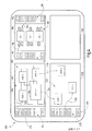
- Fig. 3 are the project data memories 52 contained in the control units 28, the project data memories 52 'contained in the safety-relevant actuators 103, the project data memories 52 "contained in the non-safety-relevant actuators 97, the project data memories 52''' contained in the non-safety-relevant sensors 95 and the project data memories 52 "" contained in the safety-relevant sensors 101.
- the individual project data memories are connected to one another via the connection unit 34.
- the entirety of the project data memories together form a virtual project memory 120 may be present between individual project data memories and the connection unit 34 are omitted.
- a programming unit is designated in its entirety with the reference numeral 122.
- the programming unit 122 essentially consists of a computer 124 which is connected to a display unit 126.
- a computer program 128 is executed on the computer 124.
- the computer program 128 enables the creation of project data 130 which represent an application running on the system to be controlled.
- the project data 130 include program data, configuration data and parameterization data.
- the computer program 128 is often referred to in technical terminology as a programming tool.
- the computer 124 can be designed as a PC and the display unit 126 as a monitor.
- the project data 130 generated with the programming unit 122 and present on the computer 124 are transferred to the project data memories 52, 52 ′, 52 ′′, 52 ′′ ′′, 52 ′′ ′′ of a distributed safety control 24 130 divided into a plurality of data packets 132, the individual data packets 132 each being assigned to one of the project data memories 52, 52 ', 52 ", 52"', 52 "" '.
- the project data more precisely the individual data packets 132, are distributed to the individual project data memories as a function of assignment data 134.
- the assignment data 134 are generated in the programming unit 122.
- the assignment data 134 can be determined, for example, as a function of at least one data processing parameter or as a function of at least one function assignment variable.
- a safety controller 24 can be designed in such a way that a programmer can choose one of these three procedures at will. But it is also conceivable that a safety controller 24 is designed such that only one or two of the procedures for the transfer of the project data 130 are provided.
- a first procedure is indicated by a sequence of arrows 136.
- both the project data 130 and the assignment data 134 are transmitted, for example in a wired manner, from the programming unit 122 via a first interface 138 provided for this purpose to the project data memory 52, which is located in the control unit 28.
- the distribution unit is a project data memory arranged in the safety controller.
- the project data memory 52 arranged in the control unit 28 distributes the data packets 132 according to the assignment data 134 to the individual project data memories 52, 52 ', 52 ", 52"', 52 “” 'contained in the safety controller 24.
- Said project data memory 52 is for this purpose designed to be able to forward project data supplied to it to at least one other project data memory.
- a second procedure is shown by a first arrow sequence 140.
- the project data 130 and the assignment data 134 are first made available on an external distribution unit 142 contained in the computer 124.
- the functionality of the external distribution unit 142 corresponds to the project data memory 52 contained in the control unit 28.
- the project data 130 are then supplied to the connection unit 34 in a wired manner via a second interface 144 provided for this purpose and, according to the assignment data 134, to the individual project data memories contained in the safety controller 24 52, 52 ', 52 ", 52"', 52 “” '.
- the external distribution unit 142 does not have to be permanently connected to the safety controller 24. It is sufficient if this is only connected for the period of data transmission, for example.
- a third procedure is indicated by a second sequence of arrows 146.
- both the project data 130 and the assignment data 134 are transferred to a mobile storage medium 148.
- the mobile storage medium 148 can be, for example, an SD card, a CF card or a USB stick.
- the mobile storage medium 148 is then stored in a Receiving unit 150 introduced.
- the project data 130 are then fed to the project data memory 52 contained in the control unit 28, which then distributes the data packets 132 according to the assignment data 134 to the project data memories 52, 52 ', 52 ", 52"', 52 "contained in the safety controller 24. '' takes over.
- the control unit 28 ′′ contains a first data processing unit 152.
- the project data required by the first data processing unit 152 are stored in the form of a data packet 132 ′ in the project data memory 52, which is contained in the control unit 28 ′′.
- the first data processing unit 152 can thus call up the project data it needs directly from this project data memory.
- the assignment data 134 are determined as a function of at least one function assignment variable.
- the project data 130 are stored in the control hardware component in which they are processed.
- the assignment data 134 are determined as a function of at least one data processing parameter.
- the data processing parameter can be, for example, the clock frequency of one of the two processors 40, 42 or the data rate of the data broker 60 or the event broker 66 or the storage capacity of a project data memory 52, 52 ', 52 ", 52"', 52 "
- the characteristic variable is automatically determined by the distribution unit in that the distribution unit queries the project data memory connected to the connection unit.
- the project data 130 are preferably distributed in such a way that they are stored in control hardware components that have a high data processing capacity.
- the project data 130 essentially arbitrarily, ie distributed without function assignment to the project data memories 52, 52 ', 52 ", 52"', 52 “”'present in a safety controller 24.
- Fig. 3 This is shown as follows:
- the project data required by a second data processing unit 154 are stored in the form of the data packet 132 ′′ in the project data memory 52, which is contained in the control unit 28 '.
- the project data are thus stored in the control unit in which They are also processed of a data packet 132 "" is stored in one of the project data memories 52 ".
- the third data processing unit 156 can then access this project data via the project data memory 52 which is contained in the control unit 28 ′.
- the project data memory 52 which is contained in the control unit 28 '.
- the project data memory 52 which is contained in the control unit 28 ', has the function of a proxy.
- at least some of the project data memories are designed to automatically forward project data to other project data memories and to request project data from other project data memories.
- the project data 130 are stored redundantly in the project data memories 52, 52 ', 52 ", 52''', 52 ''' saved.
- the project data required by a fourth data processing unit 158 are stored in the form of a data packet 132 '''' both on the project data memory 52, which is contained in the control unit 28 ', and on one of the project data memories 52''''.
- the project data of the fourth data processing unit 158 are not stored on the project data memory 52, which is contained in the control unit 28 '''.
- the fourth data processing unit 158 can either access the data packet 132 ''', which is stored on the project data memory 52 contained in the control unit 28', or on the data packet 132 '''' which is stored in one of the project data memories 52 '''' is saved. If, for example, the project data memory 52 '''' on which the data package 132 '''' is stored, or even the complete control hardware component in which this project data memory is contained, fails, the project data required by the fourth data processing unit 158 are still available , in this case on the project data memory 52, which is contained in the control unit 28 '. Project data that are primarily stored in the project data memory that is contained in the control unit in which the project data are processed can also be stored redundantly. This applies, for example, to the project data of the data package 132 '.
- Safety controls can be designed differently.
- a safety control can be used in which the non-safety-relevant sensors, the safety-relevant sensors, the non-safety-relevant actuators, the safety-relevant actuators and the control units are each equipped with project data memories, as described in Fig. 3 is shown.
- safety controls can also be used in which, for example, only the control units are equipped with project data memories.
- safety controls it is also conceivable to use safety controls that have a degree of equipment with project data memories that lies between these two examples.
- the safety-relevant sensors and the safety-relevant actuators are preferably also equipped with data memories.
- both the first interface 138 and the receiving unit 150 can be arranged in a control unit. Both can be arranged individually or together in any control hardware component. It is also conceivable that the interface 138 and / or the recording unit 150 form a structural unit together with one of the project data memories. Furthermore, it can also be provided that more than one of the project data memories built into the safety controller can be used as a distribution unit.
- the selected representation in which only one of the project data memories 52 ', 52 ", 52"', 52 "'', namely the one contained in the top drawing level contains a data packet, should not have any restrictive effect. For reasons For the sake of clarity, data packages have not been shown for the project data memories contained in the drawing levels below.
- a graphical user interface is designated in its entirety with the reference numeral 170. This graphical surface enables a programmer to create the project data 130. Overall, program data, configuration data and parameterization data are created.
- the graphical user interface 170 includes a system software component field 172 which contains a multiplicity of predefined system software components 174 in the form of graphic symbols.
- the user program and thus the program data are created by providing a large number of system software components.
- the graphical user interface 170 contains a first component field 176.
- the system software components to be provided are selected and transferred to the first component field 176, as indicated by an arrow 178.
- the first component field 176 thus contains a multiplicity of provided system software components 180.
- a component part program is created by logically linking the provided system software components 180. For this purpose, logic inputs and logic outputs of these system software components are connected to one another, which is represented by a large number of connections 182.
- new system software components be created, as indicated by the new system software component 184.
- the individual system software components can be so-called elementary components which themselves do not contain any further software components. However, it can also be a matter of so-called group components, which themselves contain further software components.
- An elementary component contains several aspect blocks. Each of these aspect blocks is assigned to one of several different control aspects, each of these control aspects representing an independent sub-aspect of the safety control.
- the system software component contains all those aspect blocks that are important for the system hardware component that the system software component represents.
- a group component contains not only the aspect blocks but also software components that can be designed as elementary or group components. By using group components, a user program with several hierarchical levels can be created.
- control aspects can advantageously be the following control aspects: standard control aspect, safety control aspect, diagnosis aspect, visualization aspect, entry control aspect, cooling aspect, access authorization aspect, maintenance aspect, locking aspect, manual operation aspect or data management aspect.
- each aspect block contained in a system software component there are at least those logic variables and / or those parameters and / or those sensor signals that are required for processing and are to be fed to the aspect block via associated inputs, and those logic variables and / or those parameters and / or those output signals which are each determined in the number of aspect blocks and output from the aspect block via associated outputs, initially determined according to their reason.
- the definition of the specific sensors and / or actuators that are to be connected to the respective aspect block is ultimately only carried out when the user program is created.
- at least some of the aspect blocks contained in a system software component are present a function program is stored in each case, which defines the aspect properties of the system hardware components for the control aspect to which the respective aspect block is assigned.
- the graphical user interface 170 furthermore contains an aspect field 186.
- a multiplicity of aspect blocks 188 are arranged in this aspect field 186. Each of these aspect blocks is assigned to the same control aspect.
- the multiplicity of aspect blocks 188 includes the aspect blocks contained in all hierarchical levels of the user program.
- the graphical user interface 170 further includes a sensor field 190.
- a multiplicity of graphical sensor symbols 192 are arranged in this sensor field 190.
- a graphic sensor symbol is provided for each sensor contained in the system to be controlled.
- the graphic surface 170 contains an actuator field 194 as a further field.
- a multiplicity of graphic actuator symbols 196 are arranged in this actuator field 194.
- a graphic actuator symbol is provided for each actuator contained in the system to be controlled.
- An aspect subprogram is created for the multiplicity of aspect blocks 188 contained in the aspect field 186. For this purpose, what is known as I / O mapping is carried out for at least some of the aspect blocks both for their inputs and for their outputs. This means that at least some of the signal inputs are assigned those sensors whose sensor signals are processed in the respective aspect block.
- control outputs are assigned actuators that are controlled with the output signals determined in the respective aspect block. This is indicated by an arrow 200 by way of example.
- the I / O mapping can also be carried out by means of textual entries in an input field 202.
- the graphical user interface 170 contains a control software component field 204 which contains a multiplicity of predefined control software components 206.
- Each of these control software components 206 represents a control hardware component that is contained in a distributed safety controller 24 can be used.
- the control hardware components are, for example, control units, sensors or actuators.
- the graphical user interface 170 also contains a second component field 208.
- the programmer of the user program can insert those control software components that represent those control hardware components from which the distributed safety controller 24 is constructed. This is done by selecting individual control software components 206 and transferring them to the second component field 208, as indicated by an arrow 210 by way of example.
- the second component field 208 thus contains a large number of provided control software components 212 Assign system software components 180 to the provided control software components 212. This is indicated by arrows 214, 216.
- Function allocation variables are generated from these allocations, and the allocation data 134 are then determined as a function of these.
- the connections 182 between the individual system software components 180 can also be taken into account.
- the I / O mapping carried out for the aspect blocks can also be taken into account.
- the assignment data 134 can, however, also be determined automatically, that is to say without the programmer making an assignment.
- the project data 130 is distributed to the individual project data memories from the point of view of the data processing capacity of the individual control hardware components.
- the programming tool is designed so that the programming unit first sends inquiries to the individual control hardware components before the start of the distribution process in order to determine the respective current data processing parameters.
- the assignment data 134 are determined exclusively as a function of data processing parameters.
- the project data are distributed according to the data processing capacity of the individual control hardware components.
- the assignment data 134 are determined exclusively as a function of function assignment variables.
- the function assignment variables represent those assignments that the programmer prescribes by assigning individual system software components to individual control software components.
- the programmer defines the distribution of the project data to the individual project data memories.
- the function allocation variables represent a storage location, in particular a project data memory, which is defined by the proximity of project data to be processed and the data required for this, which originate, for example, from a sensor or another control unit.
- the assignment data 134 can be determined both as a function of data processing parameters and as a function of function assignment parameters.
- a proposal is first made for the assignment of the project data 130 to the individual project data memories, which the programmer can then still change according to his ideas. This is a two-step process. First of all, a distribution of the project data according to the aspect of the data processing capacity is proposed, which can then be modified based on the aspect of the function assignment.
- predefined configuration data can also be stored in a database.
- the project data 130 is automatically included by providing control software components also the associated configuration data.
- configuration data can also be changed, for example by making appropriate entries in the input field 202. This can also be done, for example, after the user program has been created.
- parameterization data can be stored in a database in a corresponding manner.
- configuration data there is also the possibility of changing these or of specifying them at all.
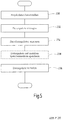
- step 230 the project data 130 are provided.
- step 232 the data packets 132 are generated.
- step 234 the assignment data 134 are generated.
- step 236 the individual data packets 132 are then distributed to the individual project data memories 52, 52 ', 52 ", 52"', 52 “” according to the assignment data 134.
- this closes step 236 does not go directly to step 234. If the data packets are distributed using a mobile storage medium 148, a step 238 is carried out between step 234 and step 236 in which the data packets 132 and the assignment data 134 are stored on the mobile storage medium 148 can be saved.
- system software components 180 are provided.
- the provided system software components 180 are linked.
- the sensors and actuators are specified for the individual aspect blocks 188, ie what is known as I / O mapping is carried out.
- Control software components 212 are provided 246.
- the system software components 180 provided are assigned to the control software components 212 provided.
Landscapes
- Engineering & Computer Science (AREA)
- General Engineering & Computer Science (AREA)
- Manufacturing & Machinery (AREA)
- Quality & Reliability (AREA)
- Physics & Mathematics (AREA)
- General Physics & Mathematics (AREA)
- Automation & Control Theory (AREA)
- Programmable Controllers (AREA)
- Safety Devices In Control Systems (AREA)
Applications Claiming Priority (3)
| Application Number | Priority Date | Filing Date | Title |
|---|---|---|---|
| DE200910019096 DE102009019096A1 (de) | 2009-04-20 | 2009-04-20 | Sicherheitssteuerung und Verfahren zum Steuern einer automatisierten Anlage |
| PCT/EP2010/002438 WO2010121798A1 (de) | 2009-04-20 | 2010-04-20 | System und verfahren zum verteilen von projektdaten einer sicherheitssteuerung einer automatisierten anlage auf die steuerungskomponenten |
| EP10719255.1A EP2422248B1 (de) | 2009-04-20 | 2010-04-20 | System und verfahren zum verteilen von projektdaten einer sicherheitssteuerung einer automatisierten anlage auf die steuerungskomponenten |
Related Parent Applications (1)
| Application Number | Title | Priority Date | Filing Date |
|---|---|---|---|
| EP10719255.1A Division EP2422248B1 (de) | 2009-04-20 | 2010-04-20 | System und verfahren zum verteilen von projektdaten einer sicherheitssteuerung einer automatisierten anlage auf die steuerungskomponenten |
Publications (2)
| Publication Number | Publication Date |
|---|---|
| EP3082002A1 EP3082002A1 (de) | 2016-10-19 |
| EP3082002B1 true EP3082002B1 (de) | 2021-09-01 |
Family
ID=42634859
Family Applications (2)
| Application Number | Title | Priority Date | Filing Date |
|---|---|---|---|
| EP10719255.1A Active EP2422248B1 (de) | 2009-04-20 | 2010-04-20 | System und verfahren zum verteilen von projektdaten einer sicherheitssteuerung einer automatisierten anlage auf die steuerungskomponenten |
| EP16169017.7A Active EP3082002B1 (de) | 2009-04-20 | 2010-04-20 | Sicherheitssteuerung und verfahren zum steuern einer automatisierten anlage |
Family Applications Before (1)
| Application Number | Title | Priority Date | Filing Date |
|---|---|---|---|
| EP10719255.1A Active EP2422248B1 (de) | 2009-04-20 | 2010-04-20 | System und verfahren zum verteilen von projektdaten einer sicherheitssteuerung einer automatisierten anlage auf die steuerungskomponenten |
Country Status (7)
| Country | Link |
|---|---|
| US (1) | US9128480B2 (ja) |
| EP (2) | EP2422248B1 (ja) |
| JP (1) | JP5815504B2 (ja) |
| CN (1) | CN102460327B (ja) |
| DE (1) | DE102009019096A1 (ja) |
| HK (1) | HK1166524A1 (ja) |
| WO (1) | WO2010121798A1 (ja) |
Families Citing this family (6)
| Publication number | Priority date | Publication date | Assignee | Title |
|---|---|---|---|---|
| EP2874030A1 (de) * | 2013-11-19 | 2015-05-20 | Siemens Aktiengesellschaft | Automatisierungssystem |
| DE102013112816A1 (de) * | 2013-11-20 | 2015-05-21 | Wieland Electric Gmbh | Sicherheitssteuerung |
| DE102015120314A1 (de) | 2015-11-24 | 2017-05-24 | Pilz Gmbh & Co. Kg | Verfahren zum Programmieren einer Sicherheitssteuerung |
| JP7398189B2 (ja) * | 2017-09-13 | 2023-12-14 | フィッシャー-ローズマウント システムズ,インコーポレイテッド | 方法、コンピューティングデバイスおよびシステム |
| DE102018206117A1 (de) * | 2018-04-20 | 2019-10-24 | Lenze Automation Gmbh | Elektrisches Antriebssystem und Verfahren zum Betreiben eines solchen |
| DE102018121885A1 (de) * | 2018-09-07 | 2020-03-12 | Phoenix Contact Gmbh & Co. Kg | Elektronisches Gerät zum Einsatz in einem Automatisierungssystem sowie ein Automatisierungssystem |
Family Cites Families (22)
| Publication number | Priority date | Publication date | Assignee | Title |
|---|---|---|---|---|
| JP3528934B2 (ja) * | 1994-03-29 | 2004-05-24 | マツダ株式会社 | 生産設備制御装置 |
| JPH07271744A (ja) * | 1994-03-31 | 1995-10-20 | Matsushita Electric Ind Co Ltd | 並列計算機 |
| US5896289A (en) * | 1996-09-05 | 1999-04-20 | Allen-Bradley Company, Llc | Output weighted partitioning method for a control program in a highly distributed control system |
| US6170044B1 (en) * | 1997-12-19 | 2001-01-02 | Honeywell Inc. | Systems and methods for synchronizing redundant controllers with minimal control disruption |
| DE19906695A1 (de) * | 1999-02-18 | 2000-08-31 | Wratil Peter | Verfahren zur automatischen Dezentralisierung von Programmen in Steuerungseinrichtungen und zur Verteilung von Intelligenz |
| JP3780732B2 (ja) * | 1999-03-10 | 2006-05-31 | 株式会社日立製作所 | 分散制御システム |
| DE60015032T2 (de) * | 1999-08-12 | 2009-10-01 | Rockwell Technologies, LLC, Thousand Oaks | Verteiltes Echtzeit-Betriebssystem |
| AU7685500A (en) | 1999-10-15 | 2001-04-23 | Omron Corporation | Network system, control method, control apparatus, and multiprocessor |
| DE10065118A1 (de) * | 2000-12-28 | 2002-07-04 | Bosch Gmbh Robert | System und Verfahren zur Steuerung und/oder Überwachung eines wenigstens zwei Steuergeräte aufweisenden Steuergeräteverbundes |
| DE10108962A1 (de) * | 2001-02-20 | 2002-09-12 | Pilz Gmbh & Co | Verfahren und Vorrichtung zum Programmieren einer Sicherheitssteuerung |
| JP2002297209A (ja) * | 2001-03-29 | 2002-10-11 | Matsushita Electric Ind Co Ltd | シーケンス制御装置におけるシーケンスプログラム格納方法 |
| WO2002097543A1 (fr) * | 2001-05-31 | 2002-12-05 | Omron Corporation | Unite securisee, systeme de commande, procede de concatenation de dispositifs de commande, procede de commande de systeme de commande, et procede de surveillance de systeme de commande |
| JP2003186507A (ja) * | 2001-12-18 | 2003-07-04 | Hitachi Ltd | 分散制御システム |
| JP2006048318A (ja) * | 2004-08-04 | 2006-02-16 | Toshiba Corp | 制御システム |
| US7424327B2 (en) * | 2005-02-04 | 2008-09-09 | Rockwell Automation Technologies, Inc. | System and method for automatically matching programmable data of devices within an industrial control system |
| WO2007075097A1 (en) | 2005-12-26 | 2007-07-05 | Siemens Aktiengesellschaft | Processing unit and method for configuring a networked automation system |
| US8166532B2 (en) * | 2006-10-10 | 2012-04-24 | Honeywell International Inc. | Decentralized access control framework |
| JP2008234394A (ja) * | 2007-03-22 | 2008-10-02 | Koyo Electronics Ind Co Ltd | プログラマブルコントローラの高速化方法 |
| JP4582167B2 (ja) * | 2007-04-27 | 2010-11-17 | ダイキン工業株式会社 | 群管理装置及び群管理プログラム |
| JP4962725B2 (ja) * | 2007-08-07 | 2012-06-27 | オムロン株式会社 | マルチplc・分散制御システムにおけるツール装置 |
| DE102009019088A1 (de) * | 2009-04-20 | 2010-11-11 | Pilz Gmbh & Co. Kg | Sicherheitssteuerung zum Steuern einer automatisierten Anlage und Verfahren zum Erstellen eines Anwenderprogramms für eine Sicherheitssteuerung |
| EP2677377B1 (en) * | 2011-01-31 | 2017-03-01 | Toyota Jidosha Kabushiki Kaisha | Safety control device and safety control method |
-
2009
- 2009-04-20 DE DE200910019096 patent/DE102009019096A1/de not_active Ceased
-
2010
- 2010-04-20 EP EP10719255.1A patent/EP2422248B1/de active Active
- 2010-04-20 EP EP16169017.7A patent/EP3082002B1/de active Active
- 2010-04-20 WO PCT/EP2010/002438 patent/WO2010121798A1/de active Application Filing
- 2010-04-20 JP JP2012506394A patent/JP5815504B2/ja active Active
- 2010-04-20 CN CN201080027561.0A patent/CN102460327B/zh active Active
-
2011
- 2011-10-19 US US13/276,862 patent/US9128480B2/en active Active
-
2012
- 2012-07-23 HK HK12107170.3A patent/HK1166524A1/zh not_active IP Right Cessation
Also Published As
| Publication number | Publication date |
|---|---|
| EP2422248B1 (de) | 2016-05-11 |
| WO2010121798A1 (de) | 2010-10-28 |
| US20120116541A1 (en) | 2012-05-10 |
| DE102009019096A1 (de) | 2010-11-04 |
| JP5815504B2 (ja) | 2015-11-17 |
| CN102460327A (zh) | 2012-05-16 |
| CN102460327B (zh) | 2014-07-30 |
| US9128480B2 (en) | 2015-09-08 |
| HK1166524A1 (zh) | 2012-11-02 |
| EP2422248A1 (de) | 2012-02-29 |
| EP3082002A1 (de) | 2016-10-19 |
| JP2012524355A (ja) | 2012-10-11 |
Similar Documents
| Publication | Publication Date | Title |
|---|---|---|
| EP2422243B1 (de) | Sicherheitssteuerung zum steuern einer automatisierten anlage und verfahren zum erstellen eines anwenderprogramms für eine sicherheitssteuerung | |
| EP1182529B1 (de) | Industrielle Steuerung auf der Basis Technologischer Objekte | |
| EP3082002B1 (de) | Sicherheitssteuerung und verfahren zum steuern einer automatisierten anlage | |
| EP2098926B1 (de) | Verfahren und Vorrichtung zum Programmieren und/oder Konfigurieren einer Sicherheitssteuerung | |
| EP1415208A1 (de) | Verfahren und prozessleitsystem zum betrieb einer technischen anlage | |
| EP2353051A1 (de) | Verfahren und vorrichtung zum erstellen eines anwenderprogramms für eine sicherheitssteuerung | |
| EP2356527B1 (de) | Sicherheitssteuerung und verfahren zum steuern einer automatisierten anlage mit einer vielzahl von anlagenhardwarekomponenten | |
| EP2098925A1 (de) | Verfahren und Vorrichtung zum Programmieren und/oder Konfigurieren einer Sicherheitssteuerung | |
| EP0782722B1 (de) | Verfahren und vorrichtung zur steuerung und aktivierung von miteinander mittels eines bussystems vernetzten sensoren und/oder aktuatoren | |
| EP4235323A2 (de) | Verfahren und vorrichtung zur automatischen validierung von sicherheitsfunktionen an einem modular aufgebauten sicherheitssystem | |
| EP2732347B1 (de) | Verfahren und system zur dynamischen verteilung von programmfunktionen in verteilten steuerungssystemen | |
| AT412131B (de) | Automatisierungssystem zur lösung einer prozesstechnischen aufgabenstellung und verfahren hierzu | |
| EP2098928A1 (de) | Verfahren und Vorrichtung zum Programmieren und/oder Konfigurieren einer Sicherheitssteuerung | |
| EP2808749B1 (de) | Verfahren zum Austausch von Steuerungsinformationen zwischen Bedien- und Beobachtungsgeräten eines industriellen Automatisierungssystems und industrielles Automatisierungssystem | |
| DE102006059708B4 (de) | Antriebssteuerung für zumindest einen elektrischen Motor | |
| EP3420426B1 (de) | Vorrichtung und verfahren zur anpassung einer numerischen steuerung an eine zu steuernde maschine | |
| EP1653308B1 (de) | System und Verfahren zur Speicherung und Bereitstellung von Informationen | |
| EP3770704A1 (de) | Cloudbasiertes dezentrales automatisierungssystem | |
| EP2480940A1 (de) | Verfahren zum bereitstellen von sicherheitsfunktionen | |
| EP2341405B1 (de) | Verfahren zum Betrieb einer Maschine | |
| EP2090948A1 (de) | Automatisierungssystem und Verfahren zum Betrieb eines solchen Automatisierungssystems | |
| EP3757688B1 (de) | Verfahren zur konfiguration einer industriellen maschine | |
| EP3553608A1 (de) | Automatisierungsanlage und verfahren zum betreiben einer automatisierungsanlage | |
| WO2005078537A2 (de) | Projektierungsverfahren für ein automatisierungssystem | |
| DE10233211A1 (de) | Computersystem zur Konfiguration von Firmware für ein Automatisierungsgerät |
Legal Events
| Date | Code | Title | Description |
|---|---|---|---|
| PUAI | Public reference made under article 153(3) epc to a published international application that has entered the european phase |
Free format text: ORIGINAL CODE: 0009012 |
|
| 17P | Request for examination filed |
Effective date: 20160510 |
|
| AC | Divisional application: reference to earlier application |
Ref document number: 2422248 Country of ref document: EP Kind code of ref document: P |
|
| AK | Designated contracting states |
Kind code of ref document: A1 Designated state(s): AT BE BG CH CY CZ DE DK EE ES FI FR GB GR HR HU IE IS IT LI LT LU LV MC MK MT NL NO PL PT RO SE SI SK SM TR |
|
| STAA | Information on the status of an ep patent application or granted ep patent |
Free format text: STATUS: EXAMINATION IS IN PROGRESS |
|
| 17Q | First examination report despatched |
Effective date: 20180412 |
|
| STAA | Information on the status of an ep patent application or granted ep patent |
Free format text: STATUS: EXAMINATION IS IN PROGRESS |
|
| GRAP | Despatch of communication of intention to grant a patent |
Free format text: ORIGINAL CODE: EPIDOSNIGR1 |
|
| STAA | Information on the status of an ep patent application or granted ep patent |
Free format text: STATUS: GRANT OF PATENT IS INTENDED |
|
| INTG | Intention to grant announced |
Effective date: 20210315 |
|
| GRAS | Grant fee paid |
Free format text: ORIGINAL CODE: EPIDOSNIGR3 |
|
| GRAA | (expected) grant |
Free format text: ORIGINAL CODE: 0009210 |
|
| STAA | Information on the status of an ep patent application or granted ep patent |
Free format text: STATUS: THE PATENT HAS BEEN GRANTED |
|
| AC | Divisional application: reference to earlier application |
Ref document number: 2422248 Country of ref document: EP Kind code of ref document: P |
|
| AK | Designated contracting states |
Kind code of ref document: B1 Designated state(s): AT BE BG CH CY CZ DE DK EE ES FI FR GB GR HR HU IE IS IT LI LT LU LV MC MK MT NL NO PL PT RO SE SI SK SM TR |
|
| REG | Reference to a national code |
Ref country code: GB Ref legal event code: FG4D Free format text: NOT ENGLISH |
|
| REG | Reference to a national code |
Ref country code: CH Ref legal event code: EP Ref country code: AT Ref legal event code: REF Ref document number: 1426874 Country of ref document: AT Kind code of ref document: T Effective date: 20210915 |
|
| REG | Reference to a national code |
Ref country code: DE Ref legal event code: R096 Ref document number: 502010016960 Country of ref document: DE |
|
| REG | Reference to a national code |
Ref country code: IE Ref legal event code: FG4D Free format text: LANGUAGE OF EP DOCUMENT: GERMAN |
|
| REG | Reference to a national code |
Ref country code: LT Ref legal event code: MG9D |
|
| REG | Reference to a national code |
Ref country code: NL Ref legal event code: MP Effective date: 20210901 |
|
| PG25 | Lapsed in a contracting state [announced via postgrant information from national office to epo] |
Ref country code: FI Free format text: LAPSE BECAUSE OF FAILURE TO SUBMIT A TRANSLATION OF THE DESCRIPTION OR TO PAY THE FEE WITHIN THE PRESCRIBED TIME-LIMIT Effective date: 20210901 Ref country code: ES Free format text: LAPSE BECAUSE OF FAILURE TO SUBMIT A TRANSLATION OF THE DESCRIPTION OR TO PAY THE FEE WITHIN THE PRESCRIBED TIME-LIMIT Effective date: 20210901 Ref country code: NO Free format text: LAPSE BECAUSE OF FAILURE TO SUBMIT A TRANSLATION OF THE DESCRIPTION OR TO PAY THE FEE WITHIN THE PRESCRIBED TIME-LIMIT Effective date: 20211201 Ref country code: BG Free format text: LAPSE BECAUSE OF FAILURE TO SUBMIT A TRANSLATION OF THE DESCRIPTION OR TO PAY THE FEE WITHIN THE PRESCRIBED TIME-LIMIT Effective date: 20211201 Ref country code: LT Free format text: LAPSE BECAUSE OF FAILURE TO SUBMIT A TRANSLATION OF THE DESCRIPTION OR TO PAY THE FEE WITHIN THE PRESCRIBED TIME-LIMIT Effective date: 20210901 Ref country code: SE Free format text: LAPSE BECAUSE OF FAILURE TO SUBMIT A TRANSLATION OF THE DESCRIPTION OR TO PAY THE FEE WITHIN THE PRESCRIBED TIME-LIMIT Effective date: 20210901 Ref country code: HR Free format text: LAPSE BECAUSE OF FAILURE TO SUBMIT A TRANSLATION OF THE DESCRIPTION OR TO PAY THE FEE WITHIN THE PRESCRIBED TIME-LIMIT Effective date: 20210901 |
|
| PG25 | Lapsed in a contracting state [announced via postgrant information from national office to epo] |
Ref country code: PL Free format text: LAPSE BECAUSE OF FAILURE TO SUBMIT A TRANSLATION OF THE DESCRIPTION OR TO PAY THE FEE WITHIN THE PRESCRIBED TIME-LIMIT Effective date: 20210901 Ref country code: LV Free format text: LAPSE BECAUSE OF FAILURE TO SUBMIT A TRANSLATION OF THE DESCRIPTION OR TO PAY THE FEE WITHIN THE PRESCRIBED TIME-LIMIT Effective date: 20210901 Ref country code: GR Free format text: LAPSE BECAUSE OF FAILURE TO SUBMIT A TRANSLATION OF THE DESCRIPTION OR TO PAY THE FEE WITHIN THE PRESCRIBED TIME-LIMIT Effective date: 20211202 |
|
| PG25 | Lapsed in a contracting state [announced via postgrant information from national office to epo] |
Ref country code: IS Free format text: LAPSE BECAUSE OF FAILURE TO SUBMIT A TRANSLATION OF THE DESCRIPTION OR TO PAY THE FEE WITHIN THE PRESCRIBED TIME-LIMIT Effective date: 20220101 Ref country code: SM Free format text: LAPSE BECAUSE OF FAILURE TO SUBMIT A TRANSLATION OF THE DESCRIPTION OR TO PAY THE FEE WITHIN THE PRESCRIBED TIME-LIMIT Effective date: 20210901 Ref country code: SK Free format text: LAPSE BECAUSE OF FAILURE TO SUBMIT A TRANSLATION OF THE DESCRIPTION OR TO PAY THE FEE WITHIN THE PRESCRIBED TIME-LIMIT Effective date: 20210901 Ref country code: RO Free format text: LAPSE BECAUSE OF FAILURE TO SUBMIT A TRANSLATION OF THE DESCRIPTION OR TO PAY THE FEE WITHIN THE PRESCRIBED TIME-LIMIT Effective date: 20210901 Ref country code: PT Free format text: LAPSE BECAUSE OF FAILURE TO SUBMIT A TRANSLATION OF THE DESCRIPTION OR TO PAY THE FEE WITHIN THE PRESCRIBED TIME-LIMIT Effective date: 20220103 Ref country code: NL Free format text: LAPSE BECAUSE OF FAILURE TO SUBMIT A TRANSLATION OF THE DESCRIPTION OR TO PAY THE FEE WITHIN THE PRESCRIBED TIME-LIMIT Effective date: 20210901 Ref country code: EE Free format text: LAPSE BECAUSE OF FAILURE TO SUBMIT A TRANSLATION OF THE DESCRIPTION OR TO PAY THE FEE WITHIN THE PRESCRIBED TIME-LIMIT Effective date: 20210901 Ref country code: CZ Free format text: LAPSE BECAUSE OF FAILURE TO SUBMIT A TRANSLATION OF THE DESCRIPTION OR TO PAY THE FEE WITHIN THE PRESCRIBED TIME-LIMIT Effective date: 20210901 |
|
| REG | Reference to a national code |
Ref country code: DE Ref legal event code: R097 Ref document number: 502010016960 Country of ref document: DE |
|
| PLBE | No opposition filed within time limit |
Free format text: ORIGINAL CODE: 0009261 |
|
| STAA | Information on the status of an ep patent application or granted ep patent |
Free format text: STATUS: NO OPPOSITION FILED WITHIN TIME LIMIT |
|
| PG25 | Lapsed in a contracting state [announced via postgrant information from national office to epo] |
Ref country code: DK Free format text: LAPSE BECAUSE OF FAILURE TO SUBMIT A TRANSLATION OF THE DESCRIPTION OR TO PAY THE FEE WITHIN THE PRESCRIBED TIME-LIMIT Effective date: 20210901 |
|
| 26N | No opposition filed |
Effective date: 20220602 |
|
| PG25 | Lapsed in a contracting state [announced via postgrant information from national office to epo] |
Ref country code: SI Free format text: LAPSE BECAUSE OF FAILURE TO SUBMIT A TRANSLATION OF THE DESCRIPTION OR TO PAY THE FEE WITHIN THE PRESCRIBED TIME-LIMIT Effective date: 20210901 |
|
| GBPC | Gb: european patent ceased through non-payment of renewal fee |
Effective date: 20220420 |
|
| REG | Reference to a national code |
Ref country code: BE Ref legal event code: MM Effective date: 20220430 |
|
| PG25 | Lapsed in a contracting state [announced via postgrant information from national office to epo] |
Ref country code: MC Free format text: LAPSE BECAUSE OF FAILURE TO SUBMIT A TRANSLATION OF THE DESCRIPTION OR TO PAY THE FEE WITHIN THE PRESCRIBED TIME-LIMIT Effective date: 20210901 Ref country code: LU Free format text: LAPSE BECAUSE OF NON-PAYMENT OF DUE FEES Effective date: 20220420 Ref country code: GB Free format text: LAPSE BECAUSE OF NON-PAYMENT OF DUE FEES Effective date: 20220420 |
|
| PG25 | Lapsed in a contracting state [announced via postgrant information from national office to epo] |
Ref country code: BE Free format text: LAPSE BECAUSE OF NON-PAYMENT OF DUE FEES Effective date: 20220430 |
|
| PG25 | Lapsed in a contracting state [announced via postgrant information from national office to epo] |
Ref country code: IE Free format text: LAPSE BECAUSE OF NON-PAYMENT OF DUE FEES Effective date: 20220420 |
|
| PGFP | Annual fee paid to national office [announced via postgrant information from national office to epo] |
Ref country code: IT Payment date: 20230426 Year of fee payment: 14 Ref country code: FR Payment date: 20230424 Year of fee payment: 14 Ref country code: DE Payment date: 20230524 Year of fee payment: 14 Ref country code: CH Payment date: 20230502 Year of fee payment: 14 |
|
| PGFP | Annual fee paid to national office [announced via postgrant information from national office to epo] |
Ref country code: AT Payment date: 20230420 Year of fee payment: 14 |
|
| PG25 | Lapsed in a contracting state [announced via postgrant information from national office to epo] |
Ref country code: HU Free format text: LAPSE BECAUSE OF FAILURE TO SUBMIT A TRANSLATION OF THE DESCRIPTION OR TO PAY THE FEE WITHIN THE PRESCRIBED TIME-LIMIT; INVALID AB INITIO Effective date: 20100420 |
|
| PG25 | Lapsed in a contracting state [announced via postgrant information from national office to epo] |
Ref country code: MK Free format text: LAPSE BECAUSE OF FAILURE TO SUBMIT A TRANSLATION OF THE DESCRIPTION OR TO PAY THE FEE WITHIN THE PRESCRIBED TIME-LIMIT Effective date: 20210901 Ref country code: CY Free format text: LAPSE BECAUSE OF FAILURE TO SUBMIT A TRANSLATION OF THE DESCRIPTION OR TO PAY THE FEE WITHIN THE PRESCRIBED TIME-LIMIT Effective date: 20210901 |