EP3081908A1 - Procede et dispositif destine a reconnaitre la presente de liquide dans un flux gazeux - Google Patents
Procede et dispositif destine a reconnaitre la presente de liquide dans un flux gazeux Download PDFInfo
- Publication number
- EP3081908A1 EP3081908A1 EP16159770.3A EP16159770A EP3081908A1 EP 3081908 A1 EP3081908 A1 EP 3081908A1 EP 16159770 A EP16159770 A EP 16159770A EP 3081908 A1 EP3081908 A1 EP 3081908A1
- Authority
- EP
- European Patent Office
- Prior art keywords
- gas
- measuring
- stage
- ultrasonic
- paths
- Prior art date
- Legal status (The legal status is an assumption and is not a legal conclusion. Google has not performed a legal analysis and makes no representation as to the accuracy of the status listed.)
- Granted
Links
- 239000007788 liquid Substances 0.000 title claims abstract description 39
- 238000000034 method Methods 0.000 title claims abstract description 35
- 238000005259 measurement Methods 0.000 claims description 50
- 238000002604 ultrasonography Methods 0.000 claims description 13
- 238000011156 evaluation Methods 0.000 claims description 8
- 239000007789 gas Substances 0.000 description 39
- 239000012530 fluid Substances 0.000 description 8
- 239000000523 sample Substances 0.000 description 8
- 238000009825 accumulation Methods 0.000 description 5
- VNWKTOKETHGBQD-UHFFFAOYSA-N methane Chemical compound C VNWKTOKETHGBQD-UHFFFAOYSA-N 0.000 description 4
- 238000001514 detection method Methods 0.000 description 2
- 239000003345 natural gas Substances 0.000 description 2
- 239000006185 dispersion Substances 0.000 description 1
- 230000010354 integration Effects 0.000 description 1
- 239000000463 material Substances 0.000 description 1
- 239000003595 mist Substances 0.000 description 1
- 239000000203 mixture Substances 0.000 description 1
- 239000002245 particle Substances 0.000 description 1
- 238000005070 sampling Methods 0.000 description 1
- 230000035945 sensitivity Effects 0.000 description 1
Images

Classifications
-
- G—PHYSICS
- G01—MEASURING; TESTING
- G01F—MEASURING VOLUME, VOLUME FLOW, MASS FLOW OR LIQUID LEVEL; METERING BY VOLUME
- G01F1/00—Measuring the volume flow or mass flow of fluid or fluent solid material wherein the fluid passes through a meter in a continuous flow
- G01F1/66—Measuring the volume flow or mass flow of fluid or fluent solid material wherein the fluid passes through a meter in a continuous flow by measuring frequency, phase shift or propagation time of electromagnetic or other waves, e.g. using ultrasonic flowmeters
- G01F1/667—Arrangements of transducers for ultrasonic flowmeters; Circuits for operating ultrasonic flowmeters
-
- G—PHYSICS
- G01—MEASURING; TESTING
- G01F—MEASURING VOLUME, VOLUME FLOW, MASS FLOW OR LIQUID LEVEL; METERING BY VOLUME
- G01F1/00—Measuring the volume flow or mass flow of fluid or fluent solid material wherein the fluid passes through a meter in a continuous flow
- G01F1/66—Measuring the volume flow or mass flow of fluid or fluent solid material wherein the fluid passes through a meter in a continuous flow by measuring frequency, phase shift or propagation time of electromagnetic or other waves, e.g. using ultrasonic flowmeters
- G01F1/662—Constructional details
-
- G—PHYSICS
- G01—MEASURING; TESTING
- G01F—MEASURING VOLUME, VOLUME FLOW, MASS FLOW OR LIQUID LEVEL; METERING BY VOLUME
- G01F1/00—Measuring the volume flow or mass flow of fluid or fluent solid material wherein the fluid passes through a meter in a continuous flow
- G01F1/66—Measuring the volume flow or mass flow of fluid or fluent solid material wherein the fluid passes through a meter in a continuous flow by measuring frequency, phase shift or propagation time of electromagnetic or other waves, e.g. using ultrasonic flowmeters
- G01F1/667—Arrangements of transducers for ultrasonic flowmeters; Circuits for operating ultrasonic flowmeters
- G01F1/668—Compensating or correcting for variations in velocity of sound
-
- G—PHYSICS
- G01—MEASURING; TESTING
- G01F—MEASURING VOLUME, VOLUME FLOW, MASS FLOW OR LIQUID LEVEL; METERING BY VOLUME
- G01F1/00—Measuring the volume flow or mass flow of fluid or fluent solid material wherein the fluid passes through a meter in a continuous flow
- G01F1/002—Measuring the volume flow or mass flow of fluid or fluent solid material wherein the fluid passes through a meter in a continuous flow wherein the flow is in an open channel
-
- G—PHYSICS
- G01—MEASURING; TESTING
- G01F—MEASURING VOLUME, VOLUME FLOW, MASS FLOW OR LIQUID LEVEL; METERING BY VOLUME
- G01F1/00—Measuring the volume flow or mass flow of fluid or fluent solid material wherein the fluid passes through a meter in a continuous flow
- G01F1/66—Measuring the volume flow or mass flow of fluid or fluent solid material wherein the fluid passes through a meter in a continuous flow by measuring frequency, phase shift or propagation time of electromagnetic or other waves, e.g. using ultrasonic flowmeters
-
- G—PHYSICS
- G01—MEASURING; TESTING
- G01F—MEASURING VOLUME, VOLUME FLOW, MASS FLOW OR LIQUID LEVEL; METERING BY VOLUME
- G01F1/00—Measuring the volume flow or mass flow of fluid or fluent solid material wherein the fluid passes through a meter in a continuous flow
- G01F1/74—Devices for measuring flow of a fluid or flow of a fluent solid material in suspension in another fluid
-
- G—PHYSICS
- G01—MEASURING; TESTING
- G01N—INVESTIGATING OR ANALYSING MATERIALS BY DETERMINING THEIR CHEMICAL OR PHYSICAL PROPERTIES
- G01N29/00—Investigating or analysing materials by the use of ultrasonic, sonic or infrasonic waves; Visualisation of the interior of objects by transmitting ultrasonic or sonic waves through the object
- G01N29/02—Analysing fluids
- G01N29/024—Analysing fluids by measuring propagation velocity or propagation time of acoustic waves
Definitions
- the invention relates to a method for detecting the presence of liquid in a gas stream flowing in a pipeline and to an ultrasonic flowmeter with which this method is carried out.
- ultrasonic meters are used for flow measurement.
- Such is from the EP 2 428 776 B1 known and has paired ultrasonic transducers, each pair defining a measuring path which is at a non-perpendicular angle to the longitudinal axis (flow direction), so that the transmitted and received ultrasonic signals propagate along the measuring paths at a certain angle other than 90 ° to the flow direction.
- the measurement principle consists in a determination of a transit time difference between two such ultrasonic signals, which run on a measurement path in the opposite direction and thus once have a component in the flow direction and once a component against the flow direction. From the measured transit time difference, the flow rate can be calculated and with knowledge of the pipe cross-section of the flow.
- z. B. be used on large natural gas pipelines to determine the amount of gas passed, become very high measurement accuracies required, since even the smallest deviations in the flow measurement with the huge amounts of natural gas can make big differences in the monetary equivalent.
- both flow velocities are the same and also have the same degree of turbulence, with turbulence in the EP 2 428 776 B1 is defined as the statistical dispersion of the individual values of flow velocities on one level. If one then forms the ratio of the turbulences from the two planes and the ratio of the flow velocities of the gas on the two planes, these ratios are ideally equal to 1. If deviations of 1 occur, this is regularly an indication of the presence of liquid. because liquid deposits at the bottom of the pipeline and therefore influences the lower measuring path more than the more distant upper measuring path. In this way, two indicators are obtained, on which one can conclude on the presence of liquid.
- a liquid warning signal is then output if an invalid reading is provided in the first stage, or if the ratio in the second stage deviates by more than a predetermined tolerance value of 1, or if in the third stage the ratio of sonic velocities is greater than one given tolerance value of 1 deviates.
- the gradation has the advantage that relatively quickly, z. B. already in the first stage, a fluid accumulation can be detected.
- the recognition principle of the second stage is in principle from the EP 2 428 776 B1 known.
- the third stage is new. It is actually expected that the accumulation of fluid away from a measuring path does not influence the speed of sound in the gas, because the speed of sound in the gas is independent of turbulence because it is only a material property.
- the first level is most insensitive but can be evaluated fastest. If only the lowest measuring path does not provide a measurement of the flow velocity of the gas, it is inside the liquid. A further evaluation on the other two levels is then no longer necessary.
- the second stage in which ratios of turbulence are formed, is more sensitive than the determination from the first stage. If liquid is detected in the second stage because the determined ratio deviates too much from 1, this is an indication of the presence of liquid and the third stage can be omitted.
- the ratio of the sound velocities of a pair of measurement paths is determined. It has been found that the ratio of sound velocities appears to be most sensitive to the presence of liquid in the pipe section. At a minimum, it has been found in practice that this ratio responds to cases that are not detected in the first two stages, so this method can be applied in the last step and smaller quantities of fluid than heretofore possible can be detected.
- a turbulence value is defined as a standard deviation over a plurality of measurements of the flow velocity of the gas on a measurement path, as in principle from US Pat EP 2 428 776 B1 known.
- the method for detecting the presence of liquid actually makes sense only when a gas flow is present, it is provided in a further development of the invention that it is checked before the first step whether the flow velocity of the gas exceeds a minimum value and the Fluid detection steps are not performed until the minimum level is exceeded.
- This minimum value can be determined on any of the measurement paths. Preferably, the minimum value at the upper level could be determined because there the presence of liquid is unlikely. But it should not be the lowest measurement path, because there is the highest probability of liquid.
- the method according to the invention can manage with a pair of measuring paths. But if there are two or more pairs of measurement paths, which then necessarily have to be arranged at different heights, a more accurate sampling of the beam profile can take place. In addition, if one measuring path fails, one or more other pairs of measuring paths can be avoided.
- measurements of different pairs of measuring paths can be used in the second and / or third step.
- a suitable combination of the measurements can result in a higher accuracy.
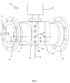
- a device 10 according to the invention has a measuring sensor 12 which consists of a pipe section 13 arranged between connecting flanges 14 and 16.
- the pipe section 13 is preferably formed in its interior circular with a nominal diameter D, corresponding to a to be connected to the connecting flanges 14 and 16, not shown piping for a gas.
- the device 10 in a tube wall 18 pairs of oppositely arranged ultrasonic transducers 20, 22, 24, 26, of which in the drawing ( FIGS. 2 and 3 ) are shown only a few and are also referred to simply as probes below.
- the ultrasonic transducers define measurement paths 30, 32, 34, 36 as will be described below ( Fig. 4 ).
- the device 10 has an evaluation unit 70, which can be attached to the sensor 12 via a mounting flange. By means of suitable cable connections, which are not shown in the drawing, the probes can be connected to the evaluation unit 70.
- the Device according to the invention for measuring the flow velocity and / or the flow rate of a fluid is preferably used as a gas meter.
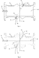
- the probes 20, 22, 24, 26 are held in probe receptacles 40, 42, 44, 46 (FIG. FIGS. 2 and 3 ), which are formed as bores in two flat receiving surfaces 56 and 58 of the tube wall 18.
- the receiving surfaces 56 and 58 are parallel to each other and are at an angle not equal to 0 ° to the central axis 60 of the pipe section 13, which also forms the Meßaufillon- and flow axis arranged ( FIGS. 2 and 3 ).
- Respective probe receptacles 40-42, 44-46 are aligned with one another, so that the probes 20, 22, 24, 26 inserted into the probe receptacles are aligned with one another and define the measurement paths 30, 32, 34, 36 ( Fig. 4 ).
- the probes send and receive ultrasound signals in a straight line in their longitudinal direction along the respective measuring path 30, 32, 34, 36.
- all measuring paths of this embodiment run parallel to one another and lie in a common vertical plane S (FIG. Fig. 4 ).
- Each measuring path is at an angle ⁇ to a plane Ev, which extends perpendicular to the central axis 60 and flow direction 72.
- the gas flow flowing through the interior of the measuring transducer 12 is determined in a known manner by first determining the flow velocity of the gas by measuring a transit time difference of ultrasonic signals which run in both directions on a measuring path and thus have a component in and against the flow direction becomes. From the flow velocity can be calculated with knowledge of the pipe cross section of the flow.
- the ultrasonic transducers serve both as a transmitter and as a receiver, so that each measuring path is used by the ultrasonic signals in both directions.
- the speed of sound SoS Speed Of Sound
- the speed of sound SoS is namely the mean of the Speeds of two ultrasound signals running in the opposite direction, ie twice the distance between the two ultrasound transducers divided by the sum of the two transit times back and forth.
- a measuring path In the ideal case of an undisturbed, homogeneous, laminar or turbulent flow, a measuring path would be sufficient to determine the flow velocity and thus the flow.
- a plurality of measuring paths are provided which scan the flow profile at different locations, that is, at different distances from the sensor axis 60. From the individual results for the measuring paths 30, 32, 34, 36 results through suitable integration process the flow.
- the measuring paths 30, 32, 34, 36 are thus arranged one above the other in parallel, horizontal planes Eu1, Eu2, Eo1, Eo2.
- the invention now requires a further special arrangement of the measuring paths.
- Two measuring paths of equal length always form a pair of measuring paths.
- the measuring paths 30 and 36 and 32 and 34 each form a pair.
- the two measurement paths are of equal length, parallel to each other, and extend in separate horizontal planes Eu1 and Eo1, and Eu2 and Eo2, respectively.
- Each horizontal plane of a pair is displaced in the vertical direction by a same, predefined distance d1 or d2 with respect to the central axis 60, so that one of the planes Eo1 and Eo2 is located in an upper region above the central axis 60 and the other plane Eu1 or Eu1 Eu2 is located in a lower region below the central axis 60.
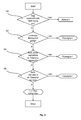
- the method according to the invention now relates to the detection of liquid 50 in the pipe section 13. For this purpose, only the measurements that are available anyway for the flow determination are used.
- the procedure is as described below and as in Fig. 5 shown schematically from:
- step 100 it is first checked in step 100 whether there is sufficient gas flow at all, because if the flow velocity of the gas does not exceed a minimum value, ie if there is no flow or too slow, the method will make no sense. Then it is not important whether a liquid 50 is present.
- This minimum value can theoretically be determined on any of the measurement paths. Preferably, the minimum value should be determined at the highest level, because there the presence of liquid is the least likely. In any case, it should not be taken the lowest measuring path, because there is the highest probability of liquid.
- a following step 102 (first stage), it is checked whether the lowest measuring path 30 delivers a valid measured value for the flow velocity of the gas. If so much liquid 50 exists in the pipe section 13 that the liquid level is above the lowest level Eu1, then the complete measuring path lies in the liquid. It would then for the speed of sound SoS nonsense for gas and thus invalid value measured and invalidate the measurement of a flow velocity. If the presence of liquid has been determined in this step 102, a liquid warning signal is output. The subsequent steps are then no longer necessary.
- a turbulence value is determined for each of the two measurement paths of a pair from a multiple measurement of the flow velocities on a measurement path in one direction and the ratio of the two turbulence values is formed.
- the turbulence value can be z. B. be defined by the standard deviation over several measurements of the flow velocity on a measurement path in one direction. If the flow is highly turbulent, the flow velocity will be more scattered than in a less turbulent flow. It is then checked whether the ratio of the turbulence values deviates by more than a predetermined tolerance value of 1. Without liquid 50 in the pipe section 13, the ratio should be 1 or at least very close to 1.
- the ratio deviates by more than 10%, for example, this may indicate the presence of fluid. How large which should be tolerance values, must be determined empirically. The tolerance values can also be different up and down. For example, they could be such that the ratio should be between 0.9 and 1.15. If the presence of liquid has been determined in this step 104, a liquid warning signal is output. The subsequent step is then no longer necessary.
- a step 106 the respective speed of sound SoS is determined on both measuring paths of a pair and the ratio of the two speeds of sound is formed. It is then tested analogously as in the turbulence values, whether the ratio of the sound velocities differs by more than a predetermined tolerance value of 1. As an example again numbers are called. Limits to the ratio could be, for example, 0.999 and 1.001.
- the method according to the invention is preferably carried out permanently and the three stages are processed cyclically one after the other.
Landscapes
- Physics & Mathematics (AREA)
- General Physics & Mathematics (AREA)
- Electromagnetism (AREA)
- Fluid Mechanics (AREA)
- Measuring Volume Flow (AREA)
- Life Sciences & Earth Sciences (AREA)
- Health & Medical Sciences (AREA)
- Chemical & Material Sciences (AREA)
- Analytical Chemistry (AREA)
- Biochemistry (AREA)
- General Health & Medical Sciences (AREA)
- Immunology (AREA)
- Pathology (AREA)
- Acoustics & Sound (AREA)
Applications Claiming Priority (1)
| Application Number | Priority Date | Filing Date | Title |
|---|---|---|---|
| DE102015105685.2A DE102015105685B3 (de) | 2015-04-14 | 2015-04-14 | Verfahren und Vorrichtung zum Erkennen des Vorhandenseins von Flüssigkeit in einem Gasstrom |
Publications (2)
| Publication Number | Publication Date |
|---|---|
| EP3081908A1 true EP3081908A1 (fr) | 2016-10-19 |
| EP3081908B1 EP3081908B1 (fr) | 2017-09-20 |
Family
ID=55312522
Family Applications (1)
| Application Number | Title | Priority Date | Filing Date |
|---|---|---|---|
| EP16159770.3A Active EP3081908B1 (fr) | 2015-04-14 | 2016-03-11 | Procédé et dispositif de détection de la présence d'un liquide dans un flux de gaz |
Country Status (6)
| Country | Link |
|---|---|
| US (1) | US10082486B2 (fr) |
| EP (1) | EP3081908B1 (fr) |
| CN (1) | CN106052780B (fr) |
| DE (1) | DE102015105685B3 (fr) |
| NO (1) | NO2744977T3 (fr) |
| RU (1) | RU2616760C1 (fr) |
Families Citing this family (7)
| Publication number | Priority date | Publication date | Assignee | Title |
|---|---|---|---|---|
| US20170212082A1 (en) * | 2016-01-21 | 2017-07-27 | Introtek International | Ultrasonic fittings |
| CN107478716B (zh) * | 2017-07-06 | 2020-07-28 | 中国船舶重工集团公司第七一九研究所 | 一种锅炉内气液二相分布场的检测装置及检测方法 |
| CH714430B1 (de) * | 2017-12-14 | 2021-10-15 | Stebatec Ag | Ultraschall-Durchflussmessvorrichtung mit strömungsoptimiertem Messrohr. |
| EP3715688B1 (fr) * | 2019-03-27 | 2021-04-28 | Siemens Schweiz AG | Soupape intégrée |
| CN211452465U (zh) * | 2019-09-30 | 2020-09-08 | 霍尼韦尔(天津)有限公司 | 超声波流量计和流体管路 |
| CN111121927B (zh) * | 2019-12-16 | 2022-07-15 | 金卡智能集团股份有限公司 | 电子式燃气表的进水检测方法 |
| CN112729488A (zh) * | 2020-12-30 | 2021-04-30 | 浙江威星智能仪表股份有限公司 | 一种超声波燃气表进水检测方法 |
Citations (3)
| Publication number | Priority date | Publication date | Assignee | Title |
|---|---|---|---|---|
| EP1186868A2 (fr) * | 2000-09-11 | 2002-03-13 | Daniel Industries, Inc., | Technique de mesure de vitesses de gaz et de liquides, et du niveau de liquide dans un écoulement stratifié dans une conduite |
| US20100010756A1 (en) * | 2008-07-08 | 2010-01-14 | Daniel Measurement And Control, Inc. | Method and System of Detecting Liquid in an Acoustic Flow Meter |
| EP2428776B1 (fr) | 2010-09-09 | 2013-08-14 | SICK Engineering GmbH | Procédé et appareil pour mesurer la vitesse de débit d'un gaz |
Family Cites Families (9)
| Publication number | Priority date | Publication date | Assignee | Title |
|---|---|---|---|---|
| DE19717940C2 (de) * | 1997-04-29 | 1999-04-15 | Krohne Ag | Ultraschall-Durchflußmeßverfahren |
| US6732595B2 (en) * | 2002-07-18 | 2004-05-11 | Panametrics, Inc. | Method of and system for determining the mass flow rate of a fluid flowing in a conduit |
| DE102005045485A1 (de) * | 2005-09-22 | 2007-04-12 | Endress + Hauser Flowtec Ag | Verfahren zur System- und/oder Prozessüberwachung bei einem Ultraschall-Durchflussmessgerät |
| DE102007004936B4 (de) * | 2006-12-19 | 2011-01-13 | Krohne Ag | Ultraschalldurchflußmeßgerät |
| US8170812B2 (en) | 2007-10-16 | 2012-05-01 | Daniel Measurement And Control, Inc. | Method and system for detecting deposit buildup within an ultrasonic flow meter |
| EP2386835B1 (fr) * | 2010-05-12 | 2015-11-25 | SICK Engineering GmbH | Mesure par ultrasons de la vitesse d'écoulement d'un fluide dans une conduite |
| DE102010040396A1 (de) * | 2010-09-08 | 2012-03-08 | Robert Bosch Gmbh | Durchflussmesser zur Erfassung einer Eigenschaft eines fluiden Mediums |
| EP2855997B1 (fr) * | 2012-05-30 | 2017-10-11 | Rubicon Research Pty Ltd. | Procédé de détection de boue dans des réseaux de fluides |
| US9581479B2 (en) * | 2013-04-08 | 2017-02-28 | Western Energy Support And Technology, Inc. | Ultrasonic meter flow measurement monitoring system |
-
2012
- 2012-06-19 NO NO12823708A patent/NO2744977T3/no unknown
-
2015
- 2015-04-14 DE DE102015105685.2A patent/DE102015105685B3/de not_active Expired - Fee Related
-
2016
- 2016-03-11 EP EP16159770.3A patent/EP3081908B1/fr active Active
- 2016-04-06 US US15/091,893 patent/US10082486B2/en active Active
- 2016-04-12 RU RU2016113799A patent/RU2616760C1/ru active
- 2016-04-14 CN CN201610235847.7A patent/CN106052780B/zh active Active
Patent Citations (3)
| Publication number | Priority date | Publication date | Assignee | Title |
|---|---|---|---|---|
| EP1186868A2 (fr) * | 2000-09-11 | 2002-03-13 | Daniel Industries, Inc., | Technique de mesure de vitesses de gaz et de liquides, et du niveau de liquide dans un écoulement stratifié dans une conduite |
| US20100010756A1 (en) * | 2008-07-08 | 2010-01-14 | Daniel Measurement And Control, Inc. | Method and System of Detecting Liquid in an Acoustic Flow Meter |
| EP2428776B1 (fr) | 2010-09-09 | 2013-08-14 | SICK Engineering GmbH | Procédé et appareil pour mesurer la vitesse de débit d'un gaz |
Also Published As
| Publication number | Publication date |
|---|---|
| RU2616760C1 (ru) | 2017-04-18 |
| US10082486B2 (en) | 2018-09-25 |
| CN106052780B (zh) | 2019-01-29 |
| US20160305911A1 (en) | 2016-10-20 |
| EP3081908B1 (fr) | 2017-09-20 |
| NO2744977T3 (fr) | 2018-07-21 |
| CN106052780A (zh) | 2016-10-26 |
| DE102015105685B3 (de) | 2016-03-03 |
Similar Documents
| Publication | Publication Date | Title |
|---|---|---|
| EP3081908B1 (fr) | Procédé et dispositif de détection de la présence d'un liquide dans un flux de gaz | |
| EP3489634A1 (fr) | Dispositif de mesure par ultrasons et procédé de mesure par ultrasons sur un fluide s'écoulant | |
| EP0046965A1 (fr) | Procédé et appareil pour la détermination dynamique du débit massique independant de la densité | |
| EP3388794B2 (fr) | Dispositif de mesure du débit destiné à mesurer le débit d'un fluide | |
| DE102014115203B3 (de) | Verfahren und Anordnung zur Ultraschall-Clamp-on-Durchflussmessung und Schaltungsanordnung zur Steuerung einer Ultraschall-Clamp-on-Durchflussmessung | |
| EP2072972B1 (fr) | Dispositif de mesure du mouvement d'un fluide dans un tuyau | |
| EP1554548B1 (fr) | Mesure du debit a l'aide du temps de parcours des ultrasons permettant de determiner la concentration de particules dans un fluide en ecoulement | |
| DE102016116072B4 (de) | Verfahren zur Erkennung von Fremdkörpern bei einem magnetisch-induktiven Durchflussmessgerät, ein magnetisch-induktives Durchflussmessgerät, eine Anordnung mit einem magnetisch-induktiven Durchflussmessgerät und eine Abfüllanlage mit einer Anordnung | |
| DE112013005279T5 (de) | Ultraschall-Signalkoppler | |
| DE102017005207A1 (de) | Verfahren zur Bestimmung des Drucks eines Fluids | |
| WO2015063323A1 (fr) | Procédé et dispositif pour déterminer la vitesse d'un milieu | |
| DE102008055032B4 (de) | Anordnung und Verfahren zur Mehrphasendurchflussmessung | |
| DE102007053105B4 (de) | Verfahren und Vorrichtung zur Volumenstrommessung von Fluiden in Rohrleitungen | |
| DE102015111642A1 (de) | Durchflussmessgerät nach dem Wirbelzählerprinzip | |
| WO2018015218A1 (fr) | Procédé et ensemble de mesure de débit par ultrasons de manière serrée sur le tube et corps permettant de réaliser la mesure | |
| DE112011102854T5 (de) | Verfahren und Vorrichtung zum Kalibrieren eines Durchflussmessgeräts | |
| DE19503714A1 (de) | Anordnung zur Bestimmung der Strömungsgeschwindigkeit eines Fluides in Rohren mit kreisförmigem Querschnitt mittels Ultraschall | |
| DE102023113539A1 (de) | Ultraschall-Durchflussmessvorrichtung zum Bestimmen eines Durchflusses eines fluiden Mediums durch eine Rohrleitung | |
| EP3748308A1 (fr) | Débitmètre à ultrasons, utilisation d'un débitmètre à ultrasons dans un organe d'arrêt et organe d'arrêt | |
| DE102009035983A1 (de) | Verfahren und Vorrichtung zur Bestimmung einer Durchflussmenge eines Fluids | |
| DE102013008437B4 (de) | Verfahren und Vorrichtung zur Erfassung von strömenden Partikeln | |
| EP3715797A2 (fr) | Débitmètre à ultrasons, procédé de fonctionnement d'un débitmètre à ultrasons, ensemble de mesure et procédé de fonctionnement d'un ensemble de mesure | |
| EP3748309A1 (fr) | Débitmètre à ultrasons, utilisation d'un débitmètre à ultrasons dans un organe d'arrêt et organe d'arrêt | |
| EP3642570B1 (fr) | Dispositif et procédés de mesure de débit par ultrasons | |
| EP4081761B1 (fr) | Procédé de surveillance d'un débit d'un milieu au moyen d'un débitmètre massique à effet coriolis et d'un appareil de mesure de pression différentielle |
Legal Events
| Date | Code | Title | Description |
|---|---|---|---|
| PUAI | Public reference made under article 153(3) epc to a published international application that has entered the european phase |
Free format text: ORIGINAL CODE: 0009012 |
|
| AK | Designated contracting states |
Kind code of ref document: A1 Designated state(s): AL AT BE BG CH CY CZ DE DK EE ES FI FR GB GR HR HU IE IS IT LI LT LU LV MC MK MT NL NO PL PT RO RS SE SI SK SM TR |
|
| AX | Request for extension of the european patent |
Extension state: BA ME |
|
| 17P | Request for examination filed |
Effective date: 20170119 |
|
| RBV | Designated contracting states (corrected) |
Designated state(s): AL AT BE BG CH CY CZ DE DK EE ES FI FR GB GR HR HU IE IS IT LI LT LU LV MC MK MT NL NO PL PT RO RS SE SI SK SM TR |
|
| 17Q | First examination report despatched |
Effective date: 20170222 |
|
| GRAP | Despatch of communication of intention to grant a patent |
Free format text: ORIGINAL CODE: EPIDOSNIGR1 |
|
| RIC1 | Information provided on ipc code assigned before grant |
Ipc: G01F 1/00 20060101ALI20170518BHEP Ipc: G01N 29/024 20060101ALI20170518BHEP Ipc: G01F 1/74 20060101ALN20170518BHEP Ipc: G01F 1/66 20060101AFI20170518BHEP |
|
| RIC1 | Information provided on ipc code assigned before grant |
Ipc: G01F 1/00 20060101ALI20170523BHEP Ipc: G01F 1/66 20060101AFI20170523BHEP Ipc: G01F 1/74 20060101ALN20170523BHEP Ipc: G01N 29/024 20060101ALI20170523BHEP |
|
| INTG | Intention to grant announced |
Effective date: 20170614 |
|
| GRAS | Grant fee paid |
Free format text: ORIGINAL CODE: EPIDOSNIGR3 |
|
| GRAA | (expected) grant |
Free format text: ORIGINAL CODE: 0009210 |
|
| AK | Designated contracting states |
Kind code of ref document: B1 Designated state(s): AL AT BE BG CH CY CZ DE DK EE ES FI FR GB GR HR HU IE IS IT LI LT LU LV MC MK MT NL NO PL PT RO RS SE SI SK SM TR |
|
| REG | Reference to a national code |
Ref country code: GB Ref legal event code: FG4D Free format text: NOT ENGLISH |
|
| REG | Reference to a national code |
Ref country code: CH Ref legal event code: EP |
|
| REG | Reference to a national code |
Ref country code: AT Ref legal event code: REF Ref document number: 930530 Country of ref document: AT Kind code of ref document: T Effective date: 20171015 |
|
| REG | Reference to a national code |
Ref country code: IE Ref legal event code: FG4D Free format text: LANGUAGE OF EP DOCUMENT: GERMAN |
|
| REG | Reference to a national code |
Ref country code: DE Ref legal event code: R096 Ref document number: 502016000147 Country of ref document: DE |
|
| REG | Reference to a national code |
Ref country code: NO Ref legal event code: T2 Effective date: 20170920 |
|
| REG | Reference to a national code |
Ref country code: NL Ref legal event code: MP Effective date: 20170920 |
|
| PG25 | Lapsed in a contracting state [announced via postgrant information from national office to epo] |
Ref country code: FI Free format text: LAPSE BECAUSE OF FAILURE TO SUBMIT A TRANSLATION OF THE DESCRIPTION OR TO PAY THE FEE WITHIN THE PRESCRIBED TIME-LIMIT Effective date: 20170920 Ref country code: SE Free format text: LAPSE BECAUSE OF FAILURE TO SUBMIT A TRANSLATION OF THE DESCRIPTION OR TO PAY THE FEE WITHIN THE PRESCRIBED TIME-LIMIT Effective date: 20170920 Ref country code: HR Free format text: LAPSE BECAUSE OF FAILURE TO SUBMIT A TRANSLATION OF THE DESCRIPTION OR TO PAY THE FEE WITHIN THE PRESCRIBED TIME-LIMIT Effective date: 20170920 Ref country code: LT Free format text: LAPSE BECAUSE OF FAILURE TO SUBMIT A TRANSLATION OF THE DESCRIPTION OR TO PAY THE FEE WITHIN THE PRESCRIBED TIME-LIMIT Effective date: 20170920 |
|
| REG | Reference to a national code |
Ref country code: LT Ref legal event code: MG4D |
|
| PG25 | Lapsed in a contracting state [announced via postgrant information from national office to epo] |
Ref country code: GR Free format text: LAPSE BECAUSE OF FAILURE TO SUBMIT A TRANSLATION OF THE DESCRIPTION OR TO PAY THE FEE WITHIN THE PRESCRIBED TIME-LIMIT Effective date: 20171221 Ref country code: RS Free format text: LAPSE BECAUSE OF FAILURE TO SUBMIT A TRANSLATION OF THE DESCRIPTION OR TO PAY THE FEE WITHIN THE PRESCRIBED TIME-LIMIT Effective date: 20170920 Ref country code: BG Free format text: LAPSE BECAUSE OF FAILURE TO SUBMIT A TRANSLATION OF THE DESCRIPTION OR TO PAY THE FEE WITHIN THE PRESCRIBED TIME-LIMIT Effective date: 20171220 Ref country code: LV Free format text: LAPSE BECAUSE OF FAILURE TO SUBMIT A TRANSLATION OF THE DESCRIPTION OR TO PAY THE FEE WITHIN THE PRESCRIBED TIME-LIMIT Effective date: 20170920 |
|
| PG25 | Lapsed in a contracting state [announced via postgrant information from national office to epo] |
Ref country code: NL Free format text: LAPSE BECAUSE OF FAILURE TO SUBMIT A TRANSLATION OF THE DESCRIPTION OR TO PAY THE FEE WITHIN THE PRESCRIBED TIME-LIMIT Effective date: 20170920 |
|
| PG25 | Lapsed in a contracting state [announced via postgrant information from national office to epo] |
Ref country code: CZ Free format text: LAPSE BECAUSE OF FAILURE TO SUBMIT A TRANSLATION OF THE DESCRIPTION OR TO PAY THE FEE WITHIN THE PRESCRIBED TIME-LIMIT Effective date: 20170920 Ref country code: ES Free format text: LAPSE BECAUSE OF FAILURE TO SUBMIT A TRANSLATION OF THE DESCRIPTION OR TO PAY THE FEE WITHIN THE PRESCRIBED TIME-LIMIT Effective date: 20170920 Ref country code: PL Free format text: LAPSE BECAUSE OF FAILURE TO SUBMIT A TRANSLATION OF THE DESCRIPTION OR TO PAY THE FEE WITHIN THE PRESCRIBED TIME-LIMIT Effective date: 20170920 |
|
| PG25 | Lapsed in a contracting state [announced via postgrant information from national office to epo] |
Ref country code: IS Free format text: LAPSE BECAUSE OF FAILURE TO SUBMIT A TRANSLATION OF THE DESCRIPTION OR TO PAY THE FEE WITHIN THE PRESCRIBED TIME-LIMIT Effective date: 20180120 Ref country code: SM Free format text: LAPSE BECAUSE OF FAILURE TO SUBMIT A TRANSLATION OF THE DESCRIPTION OR TO PAY THE FEE WITHIN THE PRESCRIBED TIME-LIMIT Effective date: 20170920 Ref country code: SK Free format text: LAPSE BECAUSE OF FAILURE TO SUBMIT A TRANSLATION OF THE DESCRIPTION OR TO PAY THE FEE WITHIN THE PRESCRIBED TIME-LIMIT Effective date: 20170920 Ref country code: EE Free format text: LAPSE BECAUSE OF FAILURE TO SUBMIT A TRANSLATION OF THE DESCRIPTION OR TO PAY THE FEE WITHIN THE PRESCRIBED TIME-LIMIT Effective date: 20170920 |
|
| REG | Reference to a national code |
Ref country code: DE Ref legal event code: R097 Ref document number: 502016000147 Country of ref document: DE |
|
| PLBE | No opposition filed within time limit |
Free format text: ORIGINAL CODE: 0009261 |
|
| STAA | Information on the status of an ep patent application or granted ep patent |
Free format text: STATUS: NO OPPOSITION FILED WITHIN TIME LIMIT |
|
| PG25 | Lapsed in a contracting state [announced via postgrant information from national office to epo] |
Ref country code: DK Free format text: LAPSE BECAUSE OF FAILURE TO SUBMIT A TRANSLATION OF THE DESCRIPTION OR TO PAY THE FEE WITHIN THE PRESCRIBED TIME-LIMIT Effective date: 20170920 |
|
| 26N | No opposition filed |
Effective date: 20180621 |
|
| PG25 | Lapsed in a contracting state [announced via postgrant information from national office to epo] |
Ref country code: MT Free format text: LAPSE BECAUSE OF FAILURE TO SUBMIT A TRANSLATION OF THE DESCRIPTION OR TO PAY THE FEE WITHIN THE PRESCRIBED TIME-LIMIT Effective date: 20170920 |
|
| PG25 | Lapsed in a contracting state [announced via postgrant information from national office to epo] |
Ref country code: SI Free format text: LAPSE BECAUSE OF FAILURE TO SUBMIT A TRANSLATION OF THE DESCRIPTION OR TO PAY THE FEE WITHIN THE PRESCRIBED TIME-LIMIT Effective date: 20170920 Ref country code: MC Free format text: LAPSE BECAUSE OF FAILURE TO SUBMIT A TRANSLATION OF THE DESCRIPTION OR TO PAY THE FEE WITHIN THE PRESCRIBED TIME-LIMIT Effective date: 20170920 |
|
| REG | Reference to a national code |
Ref country code: BE Ref legal event code: MM Effective date: 20180331 |
|
| REG | Reference to a national code |
Ref country code: IE Ref legal event code: MM4A |
|
| PG25 | Lapsed in a contracting state [announced via postgrant information from national office to epo] |
Ref country code: LU Free format text: LAPSE BECAUSE OF NON-PAYMENT OF DUE FEES Effective date: 20180311 |
|
| PG25 | Lapsed in a contracting state [announced via postgrant information from national office to epo] |
Ref country code: IE Free format text: LAPSE BECAUSE OF NON-PAYMENT OF DUE FEES Effective date: 20180311 |
|
| PG25 | Lapsed in a contracting state [announced via postgrant information from national office to epo] |
Ref country code: BE Free format text: LAPSE BECAUSE OF NON-PAYMENT OF DUE FEES Effective date: 20180331 |
|
| PG25 | Lapsed in a contracting state [announced via postgrant information from national office to epo] |
Ref country code: FR Free format text: LAPSE BECAUSE OF NON-PAYMENT OF DUE FEES Effective date: 20180331 |
|
| REG | Reference to a national code |
Ref country code: CH Ref legal event code: PL |
|
| PG25 | Lapsed in a contracting state [announced via postgrant information from national office to epo] |
Ref country code: CH Free format text: LAPSE BECAUSE OF NON-PAYMENT OF DUE FEES Effective date: 20190331 Ref country code: LI Free format text: LAPSE BECAUSE OF NON-PAYMENT OF DUE FEES Effective date: 20190331 |
|
| PG25 | Lapsed in a contracting state [announced via postgrant information from national office to epo] |
Ref country code: TR Free format text: LAPSE BECAUSE OF FAILURE TO SUBMIT A TRANSLATION OF THE DESCRIPTION OR TO PAY THE FEE WITHIN THE PRESCRIBED TIME-LIMIT Effective date: 20170920 |
|
| PG25 | Lapsed in a contracting state [announced via postgrant information from national office to epo] |
Ref country code: PT Free format text: LAPSE BECAUSE OF FAILURE TO SUBMIT A TRANSLATION OF THE DESCRIPTION OR TO PAY THE FEE WITHIN THE PRESCRIBED TIME-LIMIT Effective date: 20170920 |
|
| PG25 | Lapsed in a contracting state [announced via postgrant information from national office to epo] |
Ref country code: MK Free format text: LAPSE BECAUSE OF NON-PAYMENT OF DUE FEES Effective date: 20170920 Ref country code: RO Free format text: LAPSE BECAUSE OF FAILURE TO SUBMIT A TRANSLATION OF THE DESCRIPTION OR TO PAY THE FEE WITHIN THE PRESCRIBED TIME-LIMIT Effective date: 20170920 Ref country code: HU Free format text: LAPSE BECAUSE OF FAILURE TO SUBMIT A TRANSLATION OF THE DESCRIPTION OR TO PAY THE FEE WITHIN THE PRESCRIBED TIME-LIMIT; INVALID AB INITIO Effective date: 20160311 Ref country code: CY Free format text: LAPSE BECAUSE OF FAILURE TO SUBMIT A TRANSLATION OF THE DESCRIPTION OR TO PAY THE FEE WITHIN THE PRESCRIBED TIME-LIMIT Effective date: 20170920 |
|
| PG25 | Lapsed in a contracting state [announced via postgrant information from national office to epo] |
Ref country code: AL Free format text: LAPSE BECAUSE OF FAILURE TO SUBMIT A TRANSLATION OF THE DESCRIPTION OR TO PAY THE FEE WITHIN THE PRESCRIBED TIME-LIMIT Effective date: 20170920 |
|
| REG | Reference to a national code |
Ref country code: AT Ref legal event code: MM01 Ref document number: 930530 Country of ref document: AT Kind code of ref document: T Effective date: 20210311 |
|
| PG25 | Lapsed in a contracting state [announced via postgrant information from national office to epo] |
Ref country code: AT Free format text: LAPSE BECAUSE OF NON-PAYMENT OF DUE FEES Effective date: 20210311 |
|
| PGFP | Annual fee paid to national office [announced via postgrant information from national office to epo] |
Ref country code: DE Payment date: 20240321 Year of fee payment: 9 Ref country code: GB Payment date: 20240322 Year of fee payment: 9 |
|
| PGFP | Annual fee paid to national office [announced via postgrant information from national office to epo] |
Ref country code: NO Payment date: 20240227 Year of fee payment: 9 Ref country code: IT Payment date: 20240329 Year of fee payment: 9 |