EP3081707A1 - Anchor rail for anchoring in concrete and fixing system comprising an anchor rail - Google Patents
Anchor rail for anchoring in concrete and fixing system comprising an anchor rail Download PDFInfo
- Publication number
- EP3081707A1 EP3081707A1 EP15001143.5A EP15001143A EP3081707A1 EP 3081707 A1 EP3081707 A1 EP 3081707A1 EP 15001143 A EP15001143 A EP 15001143A EP 3081707 A1 EP3081707 A1 EP 3081707A1
- Authority
- EP
- European Patent Office
- Prior art keywords
- anchor rail
- legs
- anchor
- side walls
- toothing
- Prior art date
- Legal status (The legal status is an assumption and is not a legal conclusion. Google has not performed a legal analysis and makes no representation as to the accuracy of the status listed.)
- Granted
Links
- 238000004873 anchoring Methods 0.000 title claims abstract description 7
- 239000010960 cold rolled steel Substances 0.000 claims description 2
- 230000008719 thickening Effects 0.000 description 18
- 239000000463 material Substances 0.000 description 8
- 238000000034 method Methods 0.000 description 4
- 230000007704 transition Effects 0.000 description 4
- 238000009434 installation Methods 0.000 description 3
- 240000001439 Opuntia Species 0.000 description 2
- 235000004727 Opuntia ficus indica Nutrition 0.000 description 2
- 238000005452 bending Methods 0.000 description 2
- 230000005540 biological transmission Effects 0.000 description 2
- 238000010276 construction Methods 0.000 description 2
- 230000007423 decrease Effects 0.000 description 2
- 238000003860 storage Methods 0.000 description 2
- 229910000831 Steel Inorganic materials 0.000 description 1
- 230000009286 beneficial effect Effects 0.000 description 1
- 230000015572 biosynthetic process Effects 0.000 description 1
- 238000005097 cold rolling Methods 0.000 description 1
- 239000012141 concentrate Substances 0.000 description 1
- 238000005098 hot rolling Methods 0.000 description 1
- JEIPFZHSYJVQDO-UHFFFAOYSA-N iron(III) oxide Inorganic materials O=[Fe]O[Fe]=O JEIPFZHSYJVQDO-UHFFFAOYSA-N 0.000 description 1
- 238000012423 maintenance Methods 0.000 description 1
- 238000004519 manufacturing process Methods 0.000 description 1
- 230000002093 peripheral effect Effects 0.000 description 1
- 238000003825 pressing Methods 0.000 description 1
- 238000004080 punching Methods 0.000 description 1
- 239000010959 steel Substances 0.000 description 1
Images


Classifications
-
- E—FIXED CONSTRUCTIONS
- E04—BUILDING
- E04B—GENERAL BUILDING CONSTRUCTIONS; WALLS, e.g. PARTITIONS; ROOFS; FLOORS; CEILINGS; INSULATION OR OTHER PROTECTION OF BUILDINGS
- E04B1/00—Constructions in general; Structures which are not restricted either to walls, e.g. partitions, or floors or ceilings or roofs
- E04B1/38—Connections for building structures in general
- E04B1/41—Connecting devices specially adapted for embedding in concrete or masonry
- E04B1/4107—Longitudinal elements having an open profile, with the opening parallel to the concrete or masonry surface, i.e. anchoring rails
-
- E—FIXED CONSTRUCTIONS
- E04—BUILDING
- E04B—GENERAL BUILDING CONSTRUCTIONS; WALLS, e.g. PARTITIONS; ROOFS; FLOORS; CEILINGS; INSULATION OR OTHER PROTECTION OF BUILDINGS
- E04B1/00—Constructions in general; Structures which are not restricted either to walls, e.g. partitions, or floors or ceilings or roofs
- E04B1/38—Connections for building structures in general
- E04B1/388—Separate connecting elements
- E04B2001/389—Brackets
-
- F—MECHANICAL ENGINEERING; LIGHTING; HEATING; WEAPONS; BLASTING
- F16—ENGINEERING ELEMENTS AND UNITS; GENERAL MEASURES FOR PRODUCING AND MAINTAINING EFFECTIVE FUNCTIONING OF MACHINES OR INSTALLATIONS; THERMAL INSULATION IN GENERAL
- F16B—DEVICES FOR FASTENING OR SECURING CONSTRUCTIONAL ELEMENTS OR MACHINE PARTS TOGETHER, e.g. NAILS, BOLTS, CIRCLIPS, CLAMPS, CLIPS OR WEDGES; JOINTS OR JOINTING
- F16B37/00—Nuts or like thread-engaging members
- F16B37/04—Devices for fastening nuts to surfaces, e.g. sheets, plates
- F16B37/045—Devices for fastening nuts to surfaces, e.g. sheets, plates specially adapted for fastening in channels, e.g. sliding bolts, channel nuts
- F16B37/047—Barrel nuts
Abstract
Die Erfindung betrifft eine Ankerschiene (1) zur Verankerung im Beton und ein Befestigungssystem mit einer solchen Ankerschiene (1). Die Ankerschiene (1) weist einen im Wesentlichen C-förmigen Querschnitt auf. Die Ankerschiene (1) umfasst mindestens einen Anker (2), zwei Seitenwände (3) und zwei gegenüberliegende freie Schenkel (4, 24, 34). Zwischen den freien Schenkeln (4, 24, 34) ist ein Schlitz (5) in Längsrichtung (200) der Ankerschiene (1) gebildet. Die freien Schenkel (4, 24, 34) besitzen an ihrer dem Anker (2) abgewandten Seite und somit auf der vorderen Außenseite der Ankerschiene (1) bezogen auf die Längsrichtung (200) eine zumindest partielle Verzahnung (6, 46, 56, 66). Das Befestigungssystem umfasst ein Rastungselement (12, 32, 41, 43), das eine Verzahnung (13, 25, 33, 44) aufweist. Das Rastungselement (12, 32, 41, 43) ist an den freien Schenkeln (4, 24, 34) der Ankerschiene (1) angeordnet. Die Verzahnung (13, 25, 33, 44) des Rastungselements (12, 32, 41, 43) zeigt in Richtung der freien Schenkel (4, 24, 34) der Ankerschiene (1). Die Verzahnung (13, 25, 33) des Rastungselements (12, 32, 41, 43) greift in befestigtem Zustand des Gegenstands (10, 50) in die Verzahnung (6, 46, 56, 66) der Schenkel (4, 24, 34) ein.The invention relates to an anchor rail (1) for anchoring in concrete and a fastening system with such an anchor rail (1). The anchor rail (1) has a substantially C-shaped cross-section. The anchor rail (1) comprises at least one anchor (2), two side walls (3) and two opposite free legs (4, 24, 34). Between the free legs (4, 24, 34) a slot (5) in the longitudinal direction (200) of the anchor rail (1) is formed. The free legs (4, 24, 34) have on their side facing away from the armature (2) and thus on the front outer side of the anchor rail (1) with respect to the longitudinal direction (200) at least partial toothing (6, 46, 56, 66 ). The fastening system comprises a latching element (12, 32, 41, 43) which has a toothing (13, 25, 33, 44). The detent element (12, 32, 41, 43) is arranged on the free legs (4, 24, 34) of the anchor rail (1). The toothing (13, 25, 33, 44) of the detent element (12, 32, 41, 43) points in the direction of the free legs (4, 24, 34) of the anchor rail (1). The toothing (13, 25, 33) of the latching element (12, 32, 41, 43) engages in the attached state of the object (10, 50) in the toothing (6, 46, 56, 66) of the legs (4, 24, 34).
Description
Die vorliegende Erfindung betrifft eine Ankerschiene der im Oberbegriff des Anspruchs 1 angegebenen Gattung und ein Befestigungssystem mit einer Ankerschiene.The present invention relates to an anchor rail of the type specified in the preamble of
Eine gattungsgemäße Ankerschiene mit einem zugehörigen Befestigungselement ist aus der
Bei einem Befestigungssystem nach der
Darüber hinaus wird die Stabilität der beiden Schenkel durch die Deformierung der Schenkel während des Befestigungsvorgangs verringert. Ein Nachjustieren der Position des zu befestigenden Gegenstands durch Verschieben der Kopfschraube und des Befestigungselements in Längsrichtung der Ankerschiene ist verbunden mit einer weiteren Deformierung der freien Schenkel der Ankerschiene, da sich die Zähne des Befestigungselements an anderer Stelle als zuvor in die freien Schenkel graben. Ein solcher Nachjustierungsvorgang verringert die Stabilität der Ankerschiene insgesamt und sollte bei einem Befestigungssystem nach der
Eine Aufgabe der Erfindung ist es, eine gattungsgemäße Ankerschiene bereitzustellen, die einfach aufgebaut ist und eine große Stabilität aufweist.
Eine weitere Aufgabe der Erfindung ist es, ein Befestigungssystem mit einer Ankerschiene bereitzustellen, das auch bei Belastung durch einen mit Hilfe des Befestigungssystems an der Ankerschiene befestigten Gegenstand eine große Stabilität aufweist.An object of the invention is to provide a generic anchor rail, which is simple in construction and has great stability.
A further object of the invention is to provide a fastening system with an anchor rail, which has great stability even when loaded by an object fastened to the anchor rail by means of the fastening system.
Die Aufgabe wird bezüglich der Ankerschiene durch eine Ankerschiene mit den Merkmalen des Anspruchs 1 gelöst.The object is achieved with respect to the anchor rail by an anchor rail with the features of
Die weitere Aufgabe bezüglich des Befestigungssystems wird durch ein Befestigungssystem mit den Merkmalen des Anspruchs 12 gelöst.The further object with respect to the fastening system is achieved by a fastening system having the features of
Bezüglich der Ankerschiene ist vorgesehen, dass die freien Schenkel an ihrer dem Anker abgewandten Seite bezogen auf die Längserstreckung der Ankerschiene eine zumindest partielle Verzahnung besitzen. Die dem Anker abgewandten Seiten der freien Schenkel der Ankerschiene sind Teil der vorderen Außenseite der Ankerschiene. Mit vorderer Außenseite wird der Teil der Außenseite der Ankerschiene bezeichnet, der nach der Befestigung der Ankerschiene im Beton nicht direkt mit dem Beton in Berührung steht.With respect to the anchor rail, it is provided that the free legs have an at least partial toothing on their side facing away from the anchor relative to the longitudinal extent of the anchor rail. The armature facing away from the sides of the free legs of the anchor rail are part of the front outside of the anchor rail. Front outside is the part of the outside of the anchor rail, which is not directly in contact with the concrete after fixing the anchor rail in concrete.
Für ein Befestigungssystem zur Befestigung eines Gegenstands ist vorgesehen, dass die Ankerschiene als Teil des Befestigungssystems genutzt wird. Der Gegenstand weist einen befestigten Zustand auf. Im befestigten Zustand ist der Gegenstand fest mit der Ankerschiene verbunden. Zur Befestigung des Gegenstands ist ein Rastungselement vorgesehen, das eine Verzahnung aufweist. Vorteilhaft ist das Rastungselement getrennt von dem zu befestigenden Gegenstand ausgebildet. Es kann aber auch vorgesehen sein, dass der zu befestigende Gegenstand das Rastungselement besitzt und das Rastungselement einteilig mit dem zu befestigenden Gegenstand ausgebildet ist. Das Rastungselement ist im befestigten Zustand des Gegenstands an den freien Schenkeln der Ankerschiene angeordnet. Die Verzahnung des Rastungselements zeigt in Richtung der freien Schenkel der Ankerschiene. Die Verzahnung des Rastungselements greift im befestigten Zustand des Gegenstands in die Verzahnung der Schenkel der Ankerschiene ein.For a fastening system for fixing an object, it is provided that the anchor rail is used as part of the fastening system. The article has a fastened state. In the fastened state, the object is firmly connected to the anchor rail. For fixing the object, a detent element is provided, which has a toothing. Advantageously, the detent element is formed separately from the object to be fastened. But it can also be provided that the object to be fastened has the detent element and the detent element is formed integrally with the object to be fastened. The detent element is arranged in the attached state of the object to the free legs of the anchor rail. The toothing of the detent element points in the direction of the free legs of the anchor rail. The toothing of the locking element engages in the attached state of the object in the toothing of the legs of the anchor rail.
In vorteilhafter Weiterbildung des erfindungsgemäßen Befestigungssystems ist vorgesehen, dass das Befestigungssystem eine Kopfschraube umfasst, und dass im befestigten Zustand des Gegenstands ein Kopf der Kopfschraube in den zwischen den freien Schenkeln in Längsrichtung der Ankerschiene ausgebildeten Schlitz eingehängt ist und ein Gewindeschaft der Kopfschraube in Richtung weg vom Anker der Ankerschiene aus der Ankerschiene herausragt. Das Rastungselement weist vorteilhaft eine Durchgangsöffnung auf, und der Gewindeschaft der Kopfschraube ist zur Sicherung der Kopfschraube innerhalb der Ankerschiene durch die Durchgangsöffnung des Rastungselements gesteckt. Durch die Verwendung des verzahnten Rastungselements kann die Position des Rastungselements gegenüber der Position der Ankerschiene verändert werden, indem das befestigte Rastungselement gelöst wird und das Rastungselement um die Breite eines Zahns oder mehrerer Zähne der beiden Verzahnungen in Längsrichtung der Ankerschiene verschoben wird. Eine erneute Befestigung des zu befestigenden Gegenstandes ist ohne Verringerung der bisherigen Stabilität der Ankerschiene möglich. Der zur Befestigung des zu befestigenden Gegenstands nötige Anpressdruck führt nicht zu einer Deformation der Ankerschiene und auch nicht zu einer Deformation der Schenkel der Ankerschiene. Darüber hinaus kann für Ankerschiene und Rastungselement dasselbe Material verwendet werden. Der Härtegrad des Materials, aus dem die Ankerschiene gefertigt ist, ist nicht durch den Härtegrad des Materials, aus dem das Rastungselement gefertigt ist, begrenzt.In an advantageous embodiment of the fastening system according to the invention it is provided that the fastening system comprises a cap screw, and that in the fastened state of the article, a head of the cap screw is suspended in the formed between the free legs in the longitudinal direction of the anchor rail slot and a threaded shaft of the cap screw in the direction away from Anchor of the anchor rail protrudes from the anchor rail. The latching element advantageously has a passage opening, and the threaded shank of the cap screw is inserted to secure the cap screw within the anchor rail through the passage opening of the latching element. By using the toothed detent element, the position of the detent element relative to the position of the anchor rail can be changed by the fastened detent element is released and the detent element is displaced by the width of one tooth or more teeth of the two gears in the longitudinal direction of the anchor rail. A new attachment of the object to be fastened is possible without reducing the previous stability of the anchor rail. The necessary for fastening the object to be fastened contact pressure does not lead to a deformation of the anchor rail and not to a deformation of the legs of the anchor rail. In addition, the same material can be used for anchor rail and locking element. The degree of hardness of the material from which the anchor rail is made, is not limited by the degree of hardness of the material from which the locking element is made.
Da zur Befestigung eines Gegenstands mit Hilfe des erfindungsgemäßen Befestigungssystems keine Deformierung der Schenkel der Schiene nötig ist, ist der benötigte Anpressdruck sehr viel geringer. Aus diesem Grund muss beim Befestigen des Gegenstands weniger Kraft aufgewendet werden, weshalb die Befestigung eines Gegenstands mit Hilfe des erfindungsgemäßen Befestigungssystems einfacher ist.Since no deformation of the legs of the rail is necessary for fastening an object using the fastening system according to the invention, the required contact pressure is much lower. For this reason, less force has to be expended in attaching the article, and therefore attachment of an article using the attachment system of the present invention is easier.
Ein weiterer Vorteil des erfindungsgemäßen Befestigungssystems besteht darin, dass die verwendeten Kopfschrauben auch in Ankerschienen, bei denen die dem Anker abgewandten Seiten der freien Schenkel unverzahnt sind, verwendet werden können. Werden auf einer Baustelle aus Kostengründen sowohl Ankerschienen mit Verzahnung der vorderen Außenseite der freien Schenkel als auch Ankerschienen ohne Verzahnung verbaut, muss der Monteur zur Befestigung von Gegenständen in den beiden verschiedenen Ankerschienen keine verschiedenen Schraubentypen mit sich führen. Auch die Lagerhaltung eines Ankerschienenherstellers, der sowohl verzahnte als auch unverzahnte Ankerschienen herstellt, ist im Hinblick auf die in den Ankerschienen verwendeten Schrauben einfach. Solche Schrauben müssen für unterschiedlich große Ankerschienen mit verschiedenen Kopfgrößen, verschiedenen Gewindedurchmessern und verschiedenen Längen vorgehalten werden. Müssten für unterschiedliche Typen von Ankerschienen - verzahnt und unverzahnt - verschiedene Typen von Kopfschrauben vorgehalten werden, wäre der Lageraufwand um ein Vielfaches höher als wenn für beide Typen von Ankerschienen dieselbe Art von Schraube verwendet werden kann.Another advantage of the fastening system according to the invention is that the head screws used can also be used in anchor channels, in which the sides of the free legs facing away from the anchor are not toothed. If both anchor channels with teeth of the front outer side of the free legs and anchor rails without teeth installed on a construction site for cost reasons, the installer for fixing objects in the two different anchor channels do not have different screw types with him. The storage of an anchor rail manufacturer, which produces both toothed and untoothed anchor channels, is easy in view of the screws used in the anchor channels. Such screws must be kept for differently sized anchor channels with different head sizes, different thread diameters and different lengths. Would need for different types of anchor rails - toothed and untoothed - Different types of cap screws are held, the storage cost would be many times higher than if the same type of screw can be used for both types of anchor rails.
In vorteilhafter Weiterbildung der erfindungsgemäßen Ankerschiene besitzen die Schenkel an ihrer dem Anker abgewandten Seite bezogen auf die Längserstreckung der Ankerschiene eine durchgehende Verzahnung. Dadurch kann das Rastungselement an jeder beliebigen Stelle entlang der Längsrichtung der Ankerschiene so positioniert werden, dass ihre Verzahnung in die Verzahnung der Ankerschiene eingreift. Vorteilhaft erstreckt sich die Verzahnung des Rastungselements ebenso über die gesamte Länge des Rastungselements. In befestigtem Zustand des Gegenstands erstrecken sich die Länge des Rastungselements und die Länge der Ankerschiene in dieselbe Richtung. Wenn sich die Verzahnung der Ankerschiene über die gesamte Länge der Ankerschiene erstreckt und sich auch die Verzahnung des Rastungselements über die gesamte Länge des Rastungselements erstreckt, ist die Kontaktfläche zwischen Rastungselement und den Schenkeln der Ankerschiene vergleichsweise groß. Daraus ergibt sich in befestigtem Zustand des Gegenstands ein besserer Halt des befestigten Gegenstands.In an advantageous embodiment of the anchor rail according to the invention, the legs have on their side facing away from the armature with respect to the longitudinal extent of the anchor rail a continuous toothing. Thereby, the locking element can be positioned at any point along the longitudinal direction of the anchor rail so that their teeth engage in the toothing of the anchor rail. Advantageously, the toothing of the detent element also extends over the entire length of the detent element. In the fastened state of the article, the length of the detent element and the length of the anchor rail extend in the same direction. If the toothing of the anchor rail extends over the entire length of the anchor rail and also the toothing of the detent element extends over the entire length of the detent element, the contact surface between the detent element and the legs of the anchor rail is comparatively large. This results in a better grip of the attached object in the fastened state of the article.
In vorteilhafter Weiterbildung der erfindungsgemäßen Ankerschiene ist die Verzahnung der Schenkel quer zur Längsrichtung der Ankerschiene orientiert. Die Verzahnung verläuft dabei vorteilhaft in einem Winkel von 60° bis 120° zur Längsrichtung der Ankerschiene. Als besonders vorteilhaft wird ein Winkel von etwa 90° angesehen. Mit dem Verlauf der Verzahnung ist hierbei die Längsrichtung einzelner Zähne der Verzahnung gemeint. Wenn die Längsrichtung der Ankerschiene bei ihrem Einbau in Vertikalrichtung orientiert ist und die Verzahnung der Schenkel in einem Winkel von 90° zur Längsrichtung der Ankerschiene orientiert ist, erstrecken sich die einzelnen Zähne in Horizontalrichtung. Dadurch bieten sie zur Aufnahme der in Vertikalrichtung wirkenden Gewichtskraft des befestigten Gegenstands eine möglichst breite Fläche an. Vorteilhaft ist die Verzahnung auf dem Rastungselement des Befestigungssystems entsprechend orientiert. Die Gewichtskraft des befestigten Gegenstands wird über das Rastungselement und die Verzahnung des Rastungselements auf die Verzahnung der Schenkel der Ankerschiene übertragen und über die im Beton eingegossenen Anker der Ankerschiene in den Beton eingeleitet. Durch die Orientierung der Verzahnung der Schenkel quer zur Längsrichtung der Ankerschiene ist eine sehr gute Kraftübertragung der Gewichtskraft des befestigten Gegenstands auf den im Beton befestigten Anker der Ankerschiene gewährleistet.In an advantageous embodiment of the anchor rail according to the invention, the toothing of the legs is oriented transversely to the longitudinal direction of the anchor rail. The toothing extends advantageously at an angle of 60 ° to 120 ° to the longitudinal direction of the anchor rail. An angle of about 90 ° is considered particularly advantageous. In this case, the course of the toothing means the longitudinal direction of individual teeth of the toothing. When the longitudinal direction of the anchor rail is oriented in the vertical direction during its installation and the toothing of the legs is oriented at an angle of 90 ° to the longitudinal direction of the anchor rail, the individual teeth extend in the horizontal direction. As a result, they offer the widest possible area for receiving the vertical force of the weight of the fastened object. Advantageously, the toothing on the locking element of the fastening system is oriented accordingly. The weight of the fastened object is transmitted via the detent element and the toothing of the detent element on the teeth of the legs of the anchor rail and over the anchors of the anchor channel cast in the concrete are introduced into the concrete. Due to the orientation of the teeth of the legs transversely to the longitudinal direction of the anchor rail a very good power transmission of the weight of the fastened object is ensured on the anchored in the concrete anchor of the anchor rail.
In einer vorteilhaften Weiterbildung der erfindungsgemäßen Ankerschiene ist die Verzahnung der Schenkel in dem dem Schlitz benachbarten Bereich der Schenkel tiefer als in dem weiter vom Schlitz entfernten Bereich der Schenkel ausgebildet. Vorteilhaft ist die Verzahnung des Rastungselements des erfindungsgemäßen Befestigungssystems entsprechend angepasst, so dass die Verzahnung des Rastungselements vollständig in die Verzahnung der Schenkel der Ankerschiene eingreift. Eine tiefere Verzahnung vergrößert so die gemeinsame Kontaktfläche zwischen den Schenkeln der Ankerschiene und dem Rastungselement. Dadurch ist ein besserer Halt des Rastungselements auf den Schenkeln der Ankerschiene gewährleistet. Der Übertrag der Gewichtskraft des befestigten Gegenstands auf die Ankerschiene kann durch eine Vertiefung der Verzahnung von Rastungselement und Schenkeln der Ankerschiene weiter verbessert werden. Im Bereich des Übergangs von den Schenkeln der Ankerschiene zu den Seitenwänden der Ankerschiene könnte eine Vertiefung der Verzahnung der Schenkel jedoch zu einer geringeren Stabilität der Schenkel gegenüber einer möglichen Verbiegung der Schenkel in Richtung weg von den Ankern unter der Belastung durch die Gewichtskraft des befestigten Gegenstands führen. Um den Vorteil einer besseren Kraftübertragung durch eine tiefere Verzahnung ohne eine Verringerung der Stabilität der Schenkel gegenüber einem Aufbiegen unter Belastung zu erlangen, ist vorgesehen, dass die Tiefe der Verzahnung der Schenkel vom Bereich der Schenkel nahe der Seitenwände zum Bereich der Schenkel nahe des Schlitzes hin zunimmt. So ergibt sich eine Balance zwischen der Stabilität der Schenkel und dem Halt der Verzahnung des Rastungselements in der Verzahnung der Schenkel.In an advantageous development of the anchor rail according to the invention, the toothing of the legs is formed deeper in the region of the legs adjacent to the slot than in the region of the legs further away from the slot. Advantageously, the toothing of the detent element of the fastening system according to the invention is adapted accordingly, so that the toothing of the detent element engages completely in the toothing of the legs of the anchor rail. A deeper toothing thus increases the common contact area between the legs of the anchor rail and the detent element. This ensures a better grip of the locking element on the legs of the anchor rail. The transfer of the weight of the fastened object on the anchor rail can be further improved by a recess of the teeth of detent element and legs of the anchor rail. However, in the region of the transition from the legs of the anchor rail to the side walls of the anchor rail, a depression of the teeth of the legs could lead to a lower stability of the legs against a possible bending of the legs towards the anchors under the load of the weight of the fastened object , In order to obtain the advantage of a better power transmission by a deeper toothing without reducing the stability of the legs against bending under load, it is provided that the depth of the teeth of the legs from the region of the legs near the side walls to the region of the legs near the slot increases. This results in a balance between the stability of the legs and the maintenance of the toothing of the locking element in the toothing of the legs.
In einer weiteren vorteilhaften Weiterbildung der erfindungsgemäßen Ankerschiene ist vorgesehen, dass die Wandstärke der Schenkel von den Seitenwänden der Ankerschiene zum Schlitz der Ankerschiene hin zunimmt. Auf diese Weise kann die Verzahnung der Schenkel in der Nähe des Schlitzes der Ankerschiene tiefer ausgebildet werden als in der Nähe der Seitenwände und gleichzeitig die Dicke der Schenkel ohne Berücksichtigung der Zähne über die gesamte Erstreckung der Schenkel gleich sein. So ist die Stabilität der Schenkel über ihre gesamte Ausdehnung homogen. Es kann jedoch auch vorteilhaft sein, dass die Wandstärke der Schenkel von den Seitenwänden zum Schlitz der Ankerschiene hin abnimmt.In a further advantageous embodiment of the anchor rail according to the invention it is provided that the wall thickness of the legs increases from the side walls of the anchor rail to the slot of the anchor rail out. In this way, the teeth of the legs can be formed in the vicinity of the slot of the anchor rail deeper than in the Be close to the side walls and at the same time the thickness of the legs without regard to the teeth over the entire extension of the legs to be the same. Thus, the stability of the legs is homogeneous over their entire extent. However, it may also be advantageous that the wall thickness of the legs decreases from the side walls to the slot of the anchor rail.
Vorteilhaft bilden die dem Anker zugewandten ebenen innenseitigen Oberflächen der Schenkel mit den Seitenwänden einen Winkel < 90°. So weisen die mit den Seitenwänden verbundenen Schenkel in einem Querschnitt quer zur Längsrichtung der Ankerschiene ein hakenförmiges Profil auf. Vorteilhaft korrespondiert das Profil der zur Befestigung des zu befestigenden Gegenstands eingebrachten Kopfschraube mit dem Profil der innenseitigen Oberflächen der Schenkel. Die dem Gewindeschaft abgewandte Seite des Kopfes der Kopfschraube ist eben und orthogonal zum Gewindeschaft orientiert. Die dem Gewindeschaft zugewandte Oberfläche des Kopfes der Kopfschraube bildet mit dem Gewindeschaft einen Winkel < 90° und entspricht der Größe der Winkel, die die Seitenwände und die Schenkel einschließen. Beim Befestigen der Kopfschraube zwischen den Schenkeln der Ankerschiene kommen die dem Gewindeschaft zugewandten Oberflächen der Kopfschraube und die innenseitigen, dem Anker zugewandten Oberflächen der Schenkel der Ankerschiene bündig aufeinander zu liegen. In einem Querschnitt quer zur Längsachse der Ankerschiene durch die Kopfschraube weist der Kopf der Kopfschraube ein doppelt hakenförmiges Profil auf. Wirkt eine Querkraft auf den parallel zu den Seitenwänden der Ankerschiene orientierten Gewindeschaft quer zur Längsrichtung der Ankerschiene und quer zur Längsrichtung des Ankers, wird der Gewindeschaft nicht nur über seinen Kontakt zu einer Stirnfläche des einen Schenkels in seiner Position gehalten, sondern auch, weil die ihm zugewandte Oberfläche des ihm zugehörigen Kopfs in Kontakt mit dem anderen Schenkel steht. Die an der Kopfschraube angreifende Querkraft wird also anstatt über nur einen Schenkel über beide Schenkel in die Ankerschiene geleitet. Dies erhöht die Stabilität des Befestigungssystems gegenüber Kräften, die quer zur Längsrichtung der Ankerschiene und quer zur Längsrichtung des Ankers auf die Kopfschraube wirken.Advantageously, the armature facing planar inside surfaces of the legs with the side walls form an angle <90 °. Thus, the legs connected to the side walls in a cross-section transverse to the longitudinal direction of the anchor rail on a hook-shaped profile. Advantageously, the profile of the head screw introduced for fastening the object to be fastened corresponds to the profile of the inside surfaces of the legs. The threaded shank side facing away from the head of the cap screw is flat and oriented orthogonal to the threaded shaft. The threaded shank facing surface of the head of the cap screw forms with the threaded shaft at an angle <90 ° and corresponds to the size of the angle, which include the side walls and the legs. When attaching the cap screw between the legs of the anchor rail come the threaded shaft facing surfaces of the cap screw and the inside, the armature facing surfaces of the legs of the anchor rail flush with each other. In a cross section transverse to the longitudinal axis of the anchor rail through the cap screw, the head of the cap screw on a double hook-shaped profile. If a transverse force acts on the threaded shank oriented parallel to the side walls of the anchor rail transversely to the longitudinal direction of the anchor rail and transversely to the longitudinal direction of the anchor, the threaded shank is held in its position not only via its contact with an end face of the one limb, but also because the shank thereof facing surface of its associated head is in contact with the other leg. The transverse force acting on the cap screw is thus conducted instead of only one leg over both legs in the anchor rail. This increases the stability of the fastening system against forces acting transversely to the longitudinal direction of the anchor rail and transverse to the longitudinal direction of the armature on the cap screw.
In einer weiteren vorteilhaften Weiterbildung der erfindungsgemäßen Ankerschiene ist vorgesehen, dass die Schenkel der Ankerschiene und zumindest der an die Schenkel angrenzende Teil der Seitenwände der Ankerschiene orthogonal zueinander orientiert sind. Dabei liegen die dem Anker abgewandten Oberflächen der Schenkel in derselben Ebene. Vorteilhaft sind die Schenkel an den dem Anker abgewandten Enden der Seitenwände angeordnet, so dass die Seitenwände mit den Schenkeln Außenkanten der Ankerschiene bilden. Dadurch kann die Ankerschiene so in Beton eingegossen werden, dass die Oberflächen der Schenkel in einer Ebene mit der Oberfläche des die Ankerschiene umgebenden Betons liegen. So ist ein bündiger Übergang von den Schenkeln der Ankerschiene zu der Betonoberfläche möglich. Dadurch kann die Ankerschiene auf unauffällige und ansprechende Weise in den Beton integriert werden. Dies ist beispielsweise bei der Verwendung von Ankerschienen in Fassaden von Gebäuden sehr vorteilhaft. Bei dieser Weiterbildung der Ankerschiene kann vorteilhaft vorgesehen sein, dass sich die Verzahnung der Schenkel über die gesamte dem Anker abgewandte Fläche der Schenkel der Ankerschiene erstreckt. So ergibt sich ein einheitliches von außen wahrnehmbares Erscheinungsbild der Ankerschiene, und gleichzeitig wird durch die volle Ausnutzung der dem Anker abgewandten Flächen der Schenkel für die Verzahnung die Stabilität des Befestigungssystems erhöht, da dadurch die Oberfläche der Schenkel, die die Gewichtskraft des befestigten Gegenstands aufnimmt, vergrößert wird.In a further advantageous embodiment of the anchor rail according to the invention it is provided that the legs of the anchor rail and at least the adjacent to the legs of the side walls of the anchor rail are oriented orthogonal to each other. The armature facing away from the surfaces of the legs are in the same plane. Advantageously, the legs are arranged at the ends of the side walls facing away from the armature, so that the side walls form outer edges of the anchor rail with the legs. Thereby, the anchor rail can be poured into concrete so that the surfaces of the legs lie in a plane with the surface of the concrete surrounding the anchor rail. So a flush transition from the legs of the anchor rail to the concrete surface is possible. This allows the anchor rail to be integrated into the concrete in an unobtrusive and appealing way. This is for example when using anchor rails in facades of buildings very beneficial. In this development of the anchor rail can be advantageously provided that extends the teeth of the legs over the entire surface facing away from the armature surface of the legs of the anchor rail. This results in a uniform externally perceptible appearance of the anchor rail, and at the same time by the full utilization of the armature faces facing away from the teeth of the teeth increase the stability of the fastening system, since characterized the surface of the legs, which absorbs the weight of the fastened object, is enlarged.
Es kann aber auch vorteilhaft vorgesehen sein, dass die Seitenwände der Ankerschiene die freien Schenkel überragen. Wenn das Rastungselement getrennt vom zu befestigenden Gegenstand ausgebildet ist, ist es insbesondere vorteilhaft, wenn die Seitenwände der Ankerschiene die freien Schenkel der Ankerschiene überragen. Das getrennt vom zu befestigenden Gegenstand ausgebildete Rastungselement ist in befestigtem Zustand des Gegenstands zwischen dem befestigten Gegenstand und den freien Schenkeln der Ankerschiene angeordnet. Vorteilhaft weist der zu befestigende Gegenstand eine Öffnung zur Befestigung des Gewindeschafts der Kopfschraube auf. Die Seitenwände der Ankerschiene überragen die freien Schenkel der Ankerschiene vorteilhaft um die Randdicke des getrennt vom zu befestigenden Gegenstand ausgebildeten Rastungselements. Mit Randdicke ist hierbei die Dicke der Ränder des getrennt vom zu befestigenden Gegenstand ausgebildeten Rastungselements gemeint, die bei Verwendung eines getrennt vom zu befestigenden Gegenstand ausgebildeten Rastungselements als Teil eines Befestigungssystems den Seitenwänden zugewandt sind. Dadurch ist es möglich, dass die unverzahnte, dem Anker abgewandte Oberfläche des getrennt vom zu befestigenden Gegenstand ausgebildeten Rastungselements mit den Stirnseiten der Seitenwände in einer Ebene liegt. Die der Verzahnung abgewandte Fläche des getrennt vom zu befestigenden Gegenstand ausgebildeten Rastungselements ist eben. So kann die unverzahnte ebene Fläche des getrennt vom zu befestigenden Gegenstand ausgebildeten Rastungselements mit der Oberfläche des die Ankerschiene umgebenden Betons in einer Ebene liegen. Ein zu befestigender Gegenstand kann dadurch mit dem erfindungsgemäßen Befestigungssystem so befestigt werden, dass er nicht nur auf der unverzahnten ebenen Fläche des getrennt vom zu befestigenden Gegenstand ausgebildeten Rastungselements, sondern auch auf dem die Ankerschiene umgebenden Beton - beispielsweise einer Hauswand - anliegt. Dies erhöht die Stabilität der Befestigung insgesamt. So ist die Entstehung von Winddruck oder Windsog in einem Zwischenraum zwischen Beton und befestigtem Gegenstand kaum möglich. Die überstehenden Seitenwände verhindern, dass beim Eingießen der Ankerschiene in Beton Beton an die freien Schenkel oder den Innenraum der Ankerschiene gelangen kann.However, it can also be advantageously provided that the side walls of the anchor rail project beyond the free legs. If the latching element is formed separately from the object to be fastened, it is particularly advantageous if the side walls of the anchor rail project beyond the free legs of the anchor rail. The locking element formed separately from the object to be fastened is arranged in the fastened state of the object between the fastened object and the free legs of the anchor rail. Advantageously, the object to be fastened has an opening for fastening the threaded shaft of the cap screw. The side walls of the anchor rail project beyond the free legs of the anchor rail advantageously around the edge thickness of the detent element formed separately from the object to be fastened. With edge thickness in this case is the thickness of the edges of the formed separately from the object to be fastened Detent element meant, which face the side walls when using a formed separately from the object to be fastened detent element as part of a fastening system. This makes it possible that the untoothed, the armature facing away from the surface formed separately from the object to be fastened locking element with the end faces of the side walls lies in a plane. The tooth surface facing away from the formed separately from the object to be fastened locking element is flat. Thus, the non-toothed flat surface of the formed separately from the object to be fastened locking element with the surface of the anchor rail surrounding concrete lying in a plane. An object to be fastened can thus be fastened with the fastening system according to the invention so that it rests not only on the non-toothed flat surface of the detent element formed separately from the object to be fastened, but also on the concrete surrounding the anchor rail, for example a house wall. This increases the stability of the attachment overall. Thus, the formation of wind pressure or wind suction in a space between the concrete and the attached object is hardly possible. The protruding sidewalls prevent the pouring of the anchor rail in concrete concrete can reach the free legs or the interior of the anchor rail.
Weiterhin vorteilhaft entspricht die Breite des getrennt vom zu befestigenden Gegenstand ausgebildeten Rastungselementsdem Abstand der Innenseiten der Seitenwände. So formen die Stirnseiten der Seitenwände und die ebene unverzahnte, dem Anker abgewandte Oberfläche des getrennt vom zu befestigenden Gegenstand ausgebildeten Rastungselements im befestigten Zustand des Gegenstands eine bündige ebene Fläche. Kräfte quer zur Längsrichtung der Ankerschiene werden so vom getrennt vom befestigten Gegenstand ausgebildeten Rastungselementüber die den Seitenwänden zugewandten Stirnseiten des getrennt vom befestigten Gegenstand ausgebildeten Rastungselements auf die Seitenwände übertragen. Dies führt zu einer weiteren Erhöhung der Stabilität des Befestigungssystems insgesamt. Die Aufnahme von Kräften quer zur Längsrichtung der Ankerschiene durch die Seitenwände ist insbesondere bei einem Einbau der Ankerschiene, bei dem ihre Längsrichtung und die Längsrichtung ihrer Anker horizontal oder zumindest nicht vollständig vertikal orientiert ist, von Vorteil. Die Gewichtskraft eines an einer so verbauten Ankerschiene befestigten Gegenstands wirkt in Vertikalrichtung quer zur Längsrichtung oder zumindest nicht vollständig in Längsrichtung der Ankerschiene und der Anker. Die Seitenwände nehmen dann einen Teil der Gewichtskraft direkt über das Rastungselement auf, was zu einer Erhöhung der maximal möglichen Traglast führt.Further advantageously, the width of the locking element formed separately from the object to be fastened corresponds to the distance between the inner sides of the side walls. Thus, the end faces of the side walls and the plane, not toothed, the armature facing away from the surface formed separately from the object to be fastened locking element in the mounted state of the article form a flush planar surface. Forces transversely to the longitudinal direction of the anchor rail are thus transmitted to the side walls of the latching element formed separately from the fastened object via the end faces of the latching element formed separately from the fastened object and facing the side walls. This leads to a further increase in the stability of the fastening system as a whole. The inclusion of forces transversely to the longitudinal direction of the anchor rail through the side walls is particularly advantageous for installation of the anchor rail, in which its longitudinal direction and the longitudinal direction of its anchor is oriented horizontally or at least not completely vertically. The weight of an anchorage rail installed in this way attached article acts in the vertical direction transverse to the longitudinal direction or at least not completely in the longitudinal direction of the anchor rail and the anchor. The side walls then take part of the weight directly on the detent element, which leads to an increase in the maximum possible load.
Bei einer Ausführung der Erfindung mit Seitenwänden, die die Schenkel überragen, ist vorteilhaft vorgesehen, dass sich die Verzahnung der Außenseiten der Schenkel von dem Schlitz der Ankerschiene bis etwa zu den Ebenen erstreckt, in denen auch die Innenwände der Seitenwände liegen. Dadurch wird die Oberfläche der Schenkel, auf die die Gewichtskraft des befestigten Gegenstands über das Rastungselement übertragen wird, vergrößert. Auf diese Weise verteilt sich die übertragene Gewichtskraft auf eine größere Fläche, und die Stabilität des Befestigungssystems wird erhöht.In an embodiment of the invention with side walls which project beyond the legs, it is advantageously provided that the toothing of the outer sides of the legs extends from the slot of the anchor rail to approximately to the levels in which the inner walls of the side walls are located. Thereby, the surface of the legs, to which the weight of the fastened object is transmitted via the locking element, increased. In this way, the transmitted weight is distributed over a larger area, and the stability of the fastening system is increased.
In vorteilhafter Weiterbildung der erfindungsgemäßen Ankerschiene ist vorgesehen, dass die Ankerschiene einen Boden umfasst, an dem die Anker angeordnet sind. Die Seitenwände sind senkrecht in Bezug auf den Boden angeordnet. Die Seitenwände bilden mit dem Boden Außenkanten. Die beiden Seitenwände verlaufen parallel zueinander. Die freien Schenkel sind auf gleicher Höhe an den dem Boden abgewandten Bereichen der Seitenwände senkrecht zu den Seitenwänden angeordnet. Die freien Schenkel können jedoch auch in einem anderen Winkel zu den Seitenwänden orientiert sein. Durch die senkrechte Orientierung der Seitenwände zum Boden können quer zur Längsrichtung der Ankerschiene auftretende Kräfte effizient über die senkrechten Seitenwände in den Beton abgeleitet werden. Hierbei werden die auftretenden Kräfte zunächst über die Kopfschraube und/oder die freien Schenkel auf die Seitenwände übertragen. Die senkrechte Orientierung der Seitenwände zu dem Boden ermöglicht weiterhin die Aufnahme von typischen Kopfschrauben in die Ankerschiene. Insbesondere ist die Querschnittsgeometrie einer so gefertigten Ankerschiene optimal auf den entsprechenden Querschnitt einer Hammerkopfschraube abgestimmt.In an advantageous embodiment of the anchor rail according to the invention it is provided that the anchor rail comprises a bottom on which the anchors are arranged. The side walls are arranged vertically with respect to the floor. The side walls form outer edges with the bottom. The two side walls are parallel to each other. The free legs are arranged at the same height at the areas facing away from the bottom of the side walls perpendicular to the side walls. However, the free legs can also be oriented at a different angle to the side walls. Due to the vertical orientation of the side walls to the floor, forces occurring transversely to the longitudinal direction of the anchor rail can be efficiently discharged via the vertical side walls into the concrete. In this case, the forces occurring are first transmitted via the cap screw and / or the free legs on the side walls. The vertical orientation of the side walls to the floor further allows the inclusion of typical cap screws in the anchor rail. In particular, the cross-sectional geometry of an anchor rail produced in this way is optimally matched to the corresponding cross section of a hammer head bolt.
In vorteilhafter Weiterbildung des erfindungsgemäßen Befestigungssystems ist vorgesehen, dass das Rastungselement und die Verzahnung des Rastungselements an die Winkelstellung der freien Schenkel und an die Verzahnung der freien Schenkel so angepasst sind, dass im befestigten Zustand des zu befestigenden Gegenstands die Verzahnung des Rastungselements mit mindestens 80% ihrer Oberfläche formschlüssig auf den dem Anker abgewandten Seiten der Schenkel der Ankerschiene aufliegt. Auf diese Weise wird die Kontaktfläche zwischen Rastungselement und freien Schenkeln groß. Dadurch wird die Übertragung der Gewichtskraft des befestigten Gegenstands auf die Ankerschiene verbessert. Dadurch wird die maximal mögliche Traglast des Befestigungssystems erhöht. Darüber hinaus kann sich zwischen den Zähnen der Verzahnung des Rastungselements und den Zähnen der Verzahnung der freien Schenkel weniger Feuchtigkeit ansammeln, wodurch Rost vermieden und die Lebensdauer des Befestigungssystems verlängert wird. Der befestigte Zustand des zu befestigenden Gegenstands entspricht einem befestigten Zustand des Rastungselements. Im befestigten Zustand des Rastungselements ist das Rastungselement fest mit der Ankerschiene verbunden. Die Oberfläche der Verzahnung ist durch die gesamte, im befestigten Zustand des Gegenstands, dem Anker der Ankerschiene zugewandte Oberfläche der Verzahnung gebildet. Insbesondere ist die Oberfläche der Verzahnung durch die Summe der Flächen aller Flanken der einzelnen Zähne der Verzahnung gebildet.In an advantageous embodiment of the fastening system according to the invention it is provided that the detent element and the toothing of the detent element to the Angular position of the free legs and to the teeth of the free legs are adapted so that rests in the mounted state of the object to be fastened, the toothing of the locking element with at least 80% of its surface form-fitting manner on the side facing away from the anchor of the legs of the anchor rail. In this way, the contact area between locking element and free legs becomes large. This improves the transfer of the weight of the fastened object to the anchor rail. As a result, the maximum possible load of the fastening system is increased. In addition, between the teeth of the teeth of the locking element and the teeth of the teeth of the free legs can accumulate less moisture, thereby avoiding rust and the life of the fastening system is extended. The attached state of the object to be fastened corresponds to a fixed state of the detent element. In the fastened state of the detent element, the detent element is firmly connected to the anchor rail. The surface of the toothing is formed by the entire, in the fastened state of the article, the armature of the anchor rail facing surface of the toothing. In particular, the surface of the toothing is formed by the sum of the surfaces of all flanks of the individual teeth of the toothing.
Zweckmäßig ist ein befestigter Gegenstand mittels einer Befestigungsmutter auf dem Gewindeschaft der Kopfschraube befestigt. Vorteilhaft ist zwischen dem befestigten Gegenstand und der Befestigungsmutter eine Tellerfeder angeordnet. Die Tellerfeder hält über eine längere Zeit das Einzugsdrehmoment zwischen der Befestigungsmutter und der Kopfschraube aufrecht. Auf diese Weise wird der Lockerung der Schraubverbindung, der sogenannten Relaxation, entgegengewirkt.Suitably, a fastened object is fastened by means of a fastening nut on the threaded shank of the cap screw. Advantageously, a plate spring is arranged between the attached object and the fastening nut. The diaphragm spring maintains the retraction torque between the mounting nut and the cap screw for a long time. In this way, the loosening of the screw, the so-called relaxation, counteracted.
Vorteilhaft ist die Ankerschiene einteilig aus kaltgewalztem Stahl gefertigt. Dies trägt zu einer größeren Stabilität der Ankerschiene bei. Insbesondere die erhöhte Festigkeit der Ankerschiene sorgt für eine Erhöhung der maximal tragbaren Traglast des Befestigungssystems. Durch die erhöhte Festigkeit der Ankerschiene wird einem Verbiegen der Ankerschiene bei Belastung durch die Gewichtskraft eines befestigten Gegenstands entgegengewirkt. Darüber hinaus ist eine Herstellung im Kaltwalzverfahren deutlich kostengünstiger und energiesparender als die Herstellung im Warmwalzverfahren. Auf diese Weise kann unter Einsatz einer kleineren Energiemenge eine stabilere Ankerschiene hergestellt werden. Das Rastelement kann vorteilhaft aus Bandstahl hergestellt sein, der durch Stanzen abgelängt wurde und in den durch Pressen die Verzahnung eingebracht wurde.Advantageously, the anchor rail is made in one piece from cold-rolled steel. This contributes to a greater stability of the anchor rail. In particular, the increased strength of the anchor rail ensures an increase in the maximum portable load of the fastening system. Due to the increased strength of the anchor rail deflection of the anchor rail is counteracted under load by the weight of a fixed object. In addition, a production in the cold rolling process is significantly cheaper and more energy efficient than hot rolling. In this way, using a smaller amount of energy, a more stable anchor rail can be made. The locking element may advantageously be made of strip steel, which has been cut to length by punching and in which the teeth were introduced by pressing.
Vorteilhaft weist die Ankerschiene zur Verankerung im Beton einen im Wesentlichen C-förmigen Querschnitt auf, wobei die Ankerschiene einen im Querschnitt im Wesentlichen U-förmigen Grundkörper, zwei freie Schenkel und mindestens einen Anker umfasst, wobei der Grundkörper einen Boden und zwei Seitenwände umfasst, wobei die zwei freien Schenkel gegenüberliegend dem Boden des Grundkörpers angeordnet sind, wobei der zumindest eine Anker an dem Boden angeordnet ist, wobei zwischen den freien Schenkeln ein Schlitz in Längsrichtung der Ankerschiene gebildet ist. Vorteilhaft ist die Ankerschiene dadurch gekennzeichnet, dass die Ankerschiene mindestens eine Verdickung am Grundkörper aufweist.Advantageously, the anchor rail for anchoring in concrete has a substantially C-shaped cross-section, wherein the anchor rail comprises a cross-sectionally substantially U-shaped main body, two free legs and at least one anchor, wherein the base body comprises a bottom and two side walls, wherein the two free legs are arranged opposite to the bottom of the main body, wherein the at least one armature is arranged on the bottom, wherein between the free legs, a slot is formed in the longitudinal direction of the anchor rail. Advantageously, the anchor rail is characterized in that the anchor rail has at least one thickening on the base body.
Vorteilhaft weist die Ankerschiene zur Verankerung im Beton einen im Wesentlichen C-förmigen Querschnitt auf, wobei die Ankerschiene einen im Querschnitt im Wesentlichen U-förmigen Grundkörper, zwei freie Schenkel und mindestens einen Anker umfasst, wobei die zwei freien Schenkel gegenüberliegend zum Anker am Grundkörper angeordnet sind, wobei zwischen den freien Schenkeln ein Schlitz in Längsrichtung der Ankerschiene gebildet ist. Vorteilhaft ist die Ankerschiene dadurch gekennzeichnet, dass der Grundkörper an seiner dem Beton zugewandten Außenseite zumindest teilweise eine Profilierung aufweist.Advantageously, the anchor rail for anchoring in concrete has a substantially C-shaped cross-section, wherein the anchor rail comprises a cross-sectionally substantially U-shaped base body, two free legs and at least one anchor, wherein the two free legs arranged opposite to the armature on the base body are, between the free legs, a slot is formed in the longitudinal direction of the anchor rail. Advantageously, the anchor rail is characterized in that the base body at its concrete facing the outside at least partially has a profiling.
Ausführungsbeispiele der Erfindung werden im Folgenden anhand der Zeichnungen erläutert. Es zeigen:
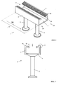
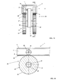
- Fig. 1
- eine perspektivische Darstellung einer Ankerschiene,
- Fig. 2
- eine Ansicht der Ankerschiene aus
Fig. 1 von einem Längsende der Ankerschiene aus in Richtung des Pfeils II inFig. 1 , - Fig. 3
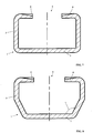
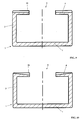
bis 11 - Teildarstellungen von Schnitten quer zur Längsrichtung von Ankerschienen ohne Darstellung der Anker,
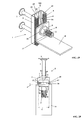
- Fig. 12
- eine perspektivische Darstellung eines Befestigungssystems, die Ankerschiene aus
Fig. 1 umfassend, - Fig. 13
- eine Ansicht des Befestigungssystems aus
Fig. 12 von einem Längsende der Ankerschiene aus in Richtung des Pfeils XIII inFig. 12 , - Fig. 14
- eine Explosionsdarstellung des Befestigungssystems aus
den Figuren 12 und 13 , - Fig. 15
- eine Ansicht in Richtung der Längsrichtung der Ankerschiene eines Befestigungssystems mit verfahrbarem Zahnradeinsatz,
- Fig. 16
- einen Schnitt längs der in
Fig. 15 gekennzeichneten Linie XVI-XVI, - Fig. 17
- eine perspektivische Darstellung einer Ankerschiene,
- Fig. 18
- eine Ansicht der Ankerschiene aus
Fig. 17 in Richtung des Pfeils XVIII inFig. 17 , - Fig. 19
- eine perspektivische Darstellung eines Befestigungssystems, die Ankerschiene aus
Fig. 17 umfassend, - Fig. 20
- eine Ansicht des Befestigungssystems aus
Fig. 19 von einem Längsende der Ankerschiene aus in Richtung des Pfeils XX inFig. 19 , - Fig. 21
- eine Explosionsdarstellung des Befestigungssystems aus den
Figuren 19 ,und 20
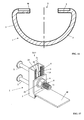
- Fig. 22
- eine perspektivische Darstellung eines Befestigungssystems ohne Darstellung von Ankern und ohne Darstellung eines zu befestigenden Gegenstands,
- Fig. 23
- eine Ansicht des Befestigungssystems aus
Fig. 22 in Richtung des Pfeils XXIII inFig. 22 ohne Darstellung von Ankern und ohne Darstellung eines zu befestigenden Gegenstands, - Fig. 24
- eine perspektivische Darstellung des getrennt von einem zu befestigenden Gegenstand ausgebildeten Rastungselements des Befestigungssystems aus
den Figuren 22 und 23 , - Fig. 25
- eine perspektivische Darstellung eines Rastungsplatteneinsatzes für das Rastungselement aus
Fig. 24 , - Fig. 26
- eine Draufsicht auf das Rastungselement aus
Fig. 24 in Richtung des Pfeils XXVI inFig. 24 , - Fig. 27
- eine Ansicht des Rastungselements aus
den Figuren 24 und26 in Richtung des Pfeils XXVII inFig. 26 , - Fig. 28
- eine Explosionsdarstellung eines Befestigungssystems, bei dem das Rastungselement einteilig mit dem zu befestigenden Gegenstand ausgebildet ist, und
- Fig. 29
- eine perspektivische Darstellung des zu befestigenden Gegenstands aus
Fig. 28 .
- Fig. 1
- a perspective view of an anchor rail,
- Fig. 2
- a view of the anchor rail
Fig. 1 from a longitudinal end of the anchor rail in the direction of arrow II inFig. 1 . - Fig. 3 to 11
- Partial representations of sections transverse to the longitudinal direction of anchor channels without representation of the anchor,
- Fig. 12
- a perspective view of a fastening system, the anchor rail
Fig. 1 full, - Fig. 13
- a view of the fastening system
Fig. 12 from a longitudinal end of the anchor rail in the direction of arrow XIII inFig. 12 . - Fig. 14
- an exploded view of the fastening system of the
Figures 12 and13 . - Fig. 15
- a view in the direction of the longitudinal direction of the anchor rail of a fastening system with movable gear insert,
- Fig. 16
- a section along the in
Fig. 15 marked line XVI-XVI, - Fig. 17
- a perspective view of an anchor rail,
- Fig. 18
- a view of the anchor rail
Fig. 17 in the direction of arrow XVIII inFig. 17 . - Fig. 19
- a perspective view of a fastening system, the anchor rail
Fig. 17 full, - Fig. 20
- a view of the fastening system
Fig. 19 from a longitudinal end of the anchor rail in the direction of the arrow XX inFig. 19 . - Fig. 21
- an exploded view of the fastening system of the
FIGS. 19 and 20 .
- Fig. 22
- a perspective view of a fastening system without representation of anchors and without representation of an object to be fastened,
- Fig. 23
- a view of the fastening system
Fig. 22 in the direction of arrow XXIII inFig. 22 without representation of anchors and without representation of an object to be fastened, - Fig. 24
- a perspective view of the formed separately from an object to be fastened locking element of the fastening system of the
Figures 22 and23 . - Fig. 25
- a perspective view of a Rastungsplatteneinsatzes for the locking element
Fig. 24 . - Fig. 26
- a plan view of the locking element
Fig. 24 in the direction of the arrow XXVI inFig. 24 . - Fig. 27
- a view of the locking element of the
Figures 24 and26 in the direction of arrow XXVII inFig. 26 . - Fig. 28
- an exploded view of a fastening system, in which the detent element is formed integrally with the object to be fastened, and
- Fig. 29
- a perspective view of the object to be fastened
Fig. 28 ,
Zwischen den beiden sich gegenüberliegenden Schenkeln 24 ist in Längsrichtung 200 der Ankerschiene 1 ein Schlitz 5 gebildet. In einer Ansicht der Ankerschiene 1 von einem Längsende der Ankerschiene 1 aus in Richtung entgegen der in
Die
Bei den Ankerschienen 1 nach den
Die freien Schenkel 4 der Ankerschienen 1 gemäß der
Die Wandstärke der Schenkel 24 der Ankerschiene 1 gemäß der
Die freien Schenkel 4, 24, 34 der Ankerschiene 1 nach den
Die Verzahnungen 6 der Außenseiten der Schenkel 24 der Ankerschiene 1 gemäß der
Alle in den
Die
In der beschriebenen Position der Hammerkopfschraube ragt der Gewindeschaft 11 der Hammerkopfschraube aus dem Schlitz 5 der Ankerschiene 1 in Richtung parallel zu den Ankern 2 aus der Ankerschiene 1 hervor. Die Position der Kopfschraube 8 in Längsrichtung 200 der Ankerschiene 1 wird mit Hilfe eines Rastungselements 12 fixiert. Das Rastungselement 12 ist getrennt von einem befestigten Gegenstand 10 ausgebildet und zwischen dem Gegenstand 10 und den Schenkeln 24 der Ankerschiene 1 angeordnet. Das Rastungselement 12 ist als Rastungsplatte ausgebildet. Wie in der
Wie in
Das Rastungselement 12 ist in diesem Ausführungsbeispiel rechteckig ausgeführt, und der Abstand der sich gegenüberliegenden parallel zueinander verlaufenden Seitenränder des Rastungselements 12 wird als Breite x bezeichnet. Die Breite x des Rastungselements 12 entspricht dem Abstand y der Innenseiten der Seitenwände 3 der Ankerschiene 1. Die Stirnseiten 14 der Seitenwände 3 und das Rastungselement 12 bilden so, wie in der
Ein zu befestigender Gegenstand 10 weist vorteilhaft eine Öffnung 40 auf, durch die dieser Gewindeschaft 11 gesteckt werden kann oder in die der Gewindeschaft 11 geschraubt werden kann. Die Öffnung 40 des Gegenstands 10 ist in der
Die in den
Die
Die kreisförmigen Außenräder 23 weisen an ihrem Rand eine umlaufende Verzahnung 25 als Teil des Rastungselements 43 auf. Die umlaufende Verzahnung 25 der Außenräder 23 korrespondiert mit der Außenverzahnung der Schenkel 4 der Ankerschiene 1. Im Ausführungsbeispiel nach der
In jedem Fall sind die Außenräder 23 der Verfahrvorrichtung 38 so auf der Ankerschiene 1 angeordnet, dass die Verzahnung 25 der Außenräder in die Verzahnung 6, 46, 56, 66 der Schenkel 4, 24, 34 der Ankerschiene 1 eingreift. Bei dem Ausführungsbeispiel nach der
Bei einem Verfahren der Verfahrvorrichtung 38 drehen sich sowohl die Außenräder 23 als auch die Innenräder 22. Wie
Durch Arretieren des Lagers 28 des Außenrads 23 und der zugeordneten Achse 27 wird eine Drehung des Außenrads 23 um die Längsachse der Achse 27 des Außenrads 23 verhindert. Dann ist keine Bewegung der Verfahrvorrichtung 38 mehr möglich, und die Position der Verfahrvorrichtung 38 in Längsrichtung der Ankerschiene 1 ist fixiert. Mit dem Befestigungssystem, bestehend aus einer Ankerschiene 1 und einer Verfahrvorrichtung 38, ist somit die Möglichkeit gegeben, einen Gegenstand gleichzeitig verfahrbar und fixierbar an einer Ankerschiene 1 zu befestigen. Hierzu kann der zu befestigende Gegenstand beispielsweise an dem Achsenträger 30 befestigt werden. Es kann auch vorgesehen sein, die Verfahrvorrichtung 38 mittels eines Motors zu verfahren. Hierzu kann beispielsweise vorgesehen sein, dass die Außenräder 23 über einen Motor angetrieben werden.By locking the bearing 28 of the
Die
Zwischen den beiden sich gegenüberliegenden Schenkeln 24 ist in Längsrichtung 200 der Ankerschiene 1 ein Schlitz 5 gebildet. In einem Querschnitt quer zur Längsrichtung 200 der Ankerschiene 1 zeigen die beiden Schenkel 24 ein hakenförmiges Profil. Die Wandstärke der Schenkel 24 nimmt von den Seitenwänden 3 der Ankerschiene 1 zum Schlitz 5 der Ankerschiene 1 hin zu.. Die den Ankern 2 abgewandten Oberflächen der freien Schenkel 24 sind mit einer Verzahnung 6 versehen. Die Verzahnung 6 der freien Schenkel 24 ist quer zur Längsrichtung 200 der Ankerschiene 1 orientiert. Die den Ankern 2 abgewandte Seite der Schenkel 24 wird auch als vordere Außenseite der Ankerschiene 1 bezeichnet. Bezogen auf die Längserstreckung 200 der Ankerschiene 1 besitzen die freien Schenkel 24 an der vorderen Außenseite der Ankerschiene 1 eine durchgehende Verzahnung 6, die sich über die gesamte Längserstreckung A der Ankerschiene 1 erstreckt. Die Verzahnung 6 der Außenseiten der Schenkel 24 erstreckt sich vom Schlitz 5 der Ankerschiene 1 bis etwa zu den Ebenen, in denen auch die Innenwände der Seitenwände 3 liegen.Between the two
Die
An den Außenseiten der Seitenwände 3 ist eine Profilierung als Seitenwandprofilierung 17 angeordnet. Die Seitenwandprofilierung 17 erstreckt sich über die in
In Richtung der Längsrichtung 200 der Ankerschiene 1 erstreckt sich die Seitenwandprofilierung 17 über die gesamte Länge A der Längserstreckung der Ankerschiene 1. Die Seitenwandprofilierung 17 besteht aus parallel zueinander angeordneten Rillen, die in die Oberfläche der Seitenwände 3 eingebracht sind. Wie in
In
Die
In der beschriebenen Position der Hammerkopfschraube ragt der Gewindeschaft 11 der Hammerkopfschraube aus dem Schlitz 5 der Ankerschiene 1 in Richtung parallel zu den Ankern 2 aus der Ankerschiene 1 hervor. Die Position der Kopfschraube 8 in Längsrichtung 200 der Ankerschiene 1 wird mit Hilfe eines Rastungselements 12 fixiert. Das Rastungselement 12 ist getrennt von einem an der Ankerschiene 1 befestigten Gegenstand 10 ausgebildet und zwischen dem befestigten Gegenstand 10 und der den Ankern 2 abgewandten Außenseite der Schenkel 24 der Ankerschiene 1 angeordnet. Wie in der
Wie in der
Das Rastungselement 12 ist in diesem Ausführungsbeispiel getrennt vom Gegenstand 10 und rechteckig ausgeführt, und der Abstand der sich gegenüberliegenden parallel zueinander verlaufenden Seitenränder des Rastungselements 12 wird als Breite x bezeichnet. Die Breite x des Rastungselements 12 entspricht dem Abstand y der Innenseiten der Seitenwände 3 der Ankerschiene 1 auf Höhe der an den Seitenwänden 3 angeordneten Schenkel 24. Die Stirnseiten 14 der Seitenwände 3 und das Rastungselement 12 bilden so, wie in der
Ein zu befestigender Gegenstand 10 muss eine Öffnung 40 aufweisen, durch die dieser Gewindeschaft 11 gesteckt werden kann oder in die der Gewindeschaft 11 geschraubt werden kann. In der
Die in den
Die
Die Funktion des Rastungselements 32 ist in der
Zur Vormontage der Kopfschraube 8 und des Rastungselements 32 in der Ankerschiene 1 wird der Rastungsplatteneinsatz 31 so weit auf den Gewindeschaft 11 der Kopfschraube 8 aufgeschraubt, dass er bündig in der Aussparung 35 des getrennt von einem zu befestigenden Gegenstand ausgebildeten Rastungselements 32 zu liegen kommt. Dabei wird der Kopf der Kopfschraube 8 gegen die dem Boden 7 zugewandten Innenseiten der Schenkel 24 gedrückt. Gleichzeitig greift die Verzahnung 13 (
Die
Die
Die
Claims (16)
dadurch gekennzeichnet, dass die freien Schenkel (4, 24, 34) an ihrer dem Anker (2) abgewandten Seite, und somit auf der vorderen Außenseite der Ankerschiene (1) bezogen auf die Längsrichtung (200) eine zumindest partielle Verzahnung (6, 46, 56, 66) besitzen.Anchor rail for anchoring in concrete with a substantially C-shaped cross-section, wherein the anchor rail (1) at least one anchor (2), two side walls (3) and two opposite free legs (4, 24, 34), wherein between the free Legs (4, 24, 34) a slot (5) in the longitudinal direction (200) of the anchor rail (1) is formed,
characterized in that the free legs (4, 24, 34) facing away from the armature (2) side, and hence on the front outside of the anchor rail (1) relative to the longitudinal direction (200) at least a partial toothing (6, 46 , 56, 66).
dadurch gekennzeichnet, dass die Schenkel (4, 24, 34) an ihrer dem Anker (2) abgewandten Seite, und somit auf der vorderen Außenseite der Ankerschiene (1) bezogen auf die Längsrichtung (200) eine durchgehende Verzahnung (6, 46, 56, 66) besitzen.Anchor rail according to claim 1,
characterized in that the legs (4, 24, 34) on its side facing away from the armature (2), and thus on the front outer side of the anchor rail (1) with respect to the longitudinal direction (200) has a continuous toothing (6, 46, 56 , 66).
dadurch gekennzeichnet, dass die Verzahnung (6, 46, 56, 66) der Schenkel (4, 24, 34) quer zur Längsrichtung (200) der Ankerschiene (1) orientiert ist.Anchor rail according to claim 1 or 2,
characterized in that the toothing (6, 46, 56, 66) of the legs (4, 24, 34) is oriented transversely to the longitudinal direction (200) of the anchor rail (1).
dadurch gekennzeichnet, dass die Verzahnung (6, 56) der Schenkel (4, 24, 34) in dem dem Schlitz (5) benachbarten Bereich der Schenkel (4, 24, 34) tiefer ist als im weiter vom Schlitz (5) entfernten Bereich der Schenkel (4, 24, 34).An anchor rail according to one of claims 1 to 3,
characterized in that the toothing (6, 56) of the legs (4, 24, 34) in the slot (5) adjacent portion of the legs (4, 24, 34) is deeper than in the farther from the slot (5) remote area the leg (4, 24, 34).
dadurch gekennzeichnet, dass die Wandstärke der Schenkel (24) von den Seitenwänden (3) der Ankerschiene (1) zum Schlitz (5) der Ankerschiene (1) hin zunimmt.An anchorage rail according to one of claims 1 to 4,
characterized in that the wall thickness of the legs (24) from the side walls (3) of the anchor rail (1) to the slot (5) of the anchor rail (1) increases towards.
dadurch gekennzeichnet, dass die Schenkel (4, 24) der Ankerschiene (1) und zumindest der an die Schenkel (4, 24) angrenzende Teil der Seitenwände (3) der Ankerschiene (1) orthogonal zueinander orientiert sind, und dass die dem Anker (2) abgewandten Oberflächen der Schenkel (4, 24) in derselben Ebene liegen.Anchor rail according to one of claims 1 to 5,
characterized in that the legs (4, 24) of the anchor rail (1) and at least the part of the side walls (3) of the anchor rail (1) adjoining the legs (4, 24) are oriented orthogonally to each other, and that the armature ( 2) facing away from surfaces of the legs (4, 24) lie in the same plane.
dadurch gekennzeichnet, dass die Ankerschiene (1) einen ebenen Boden (7) umfasst, an dem der zumindest eine Anker (2) angeordnet ist, dass die Seitenwände (3) senkrecht in Bezug auf den Boden (7) angeordnet sind, dass die Seitenwände (3) mit dem Boden (7) Außenkanten bilden, dass die Seitenwände (3) parallel zueinander verlaufen, und dass die freien (4, 24) Schenkel auf gleicher Höhe an dem dem Boden (7) abgewandten Bereich der Seitenwände (3) senkrecht zu den Seitenwänden (3) angeordnet sind.Anchor rail according to one of claims 1 to 5,
characterized in that the anchor rail (1) comprises a flat floor (7) on which the at least one anchor (2) is arranged such that the side walls (3) are perpendicular with respect to the floor (7), that the side walls (3) with the bottom (7) form outer edges, that the side walls (3) parallel to each other, and that the free (4, 24) legs at the same height at the bottom (7) facing away from the region of the side walls (3) perpendicular are arranged to the side walls (3).
dadurch gekennzeichnet, dass sich die Verzahnung (6, 46) der Außenseiten der Schenkel (4, 24, 34) von dem Schlitz (5) der Ankerschiene (1) bis etwa zu den Ebenen erstreckt, in denen auch die Innenwände der Seitenwände (3) liegen.Anchor rail according to one of claims 1 to 7,
characterized in that the toothing (6, 46) of the outer sides of the legs (4, 24, 34) from the slot (5) of the anchor rail (1) extends approximately to the planes in which the inner walls of the side walls (3 ) lie.
dadurch gekennzeichnet, dass sich die Verzahnung (56, 66) der Schenkel (4, 24, 34) über die gesamte dem Anker (2) abgewandte Fläche der Schenkel (4, 24, 34) der Ankerschiene (1) erstreckt.Anchor rail according to one of claims 1 to 7,
characterized in that the toothing (56, 66) of the legs (4, 24, 34) over the entire armature (2) facing away from the surface of the legs (4, 24, 34) of the anchor rail (1).
dadurch gekennzeichnet, dass die Seitenwände (3) die freien Schenkel (4, 24, 34) überragen.Anchor rail according to one of claims 1 to 8,
characterized in that the side walls (3) overhang the free legs (4, 24, 34).
dadurch gekennzeichnet, dass die Ankerschiene (1) aus kaltgewalztem Stahl besteht.An anchor rail according to one of claims 1 to 10,
characterized in that the anchor rail (1) consists of cold-rolled steel.
wobei ein Rastungselement (12, 32, 41, 43) vorgesehen ist, das eine Verzahnung (13, 25, 33, 44) aufweist, dass das Rastungselement (12, 32, 41, 43) an den freien Schenkeln (4, 24, 34) der Ankerschiene (1) angeordnet ist, dass die Verzahnung (13, 25, 33, 44) des Rastungselements (12, 32, 41, 43) in Richtung der freien Schenkel (4, 24, 34) der Ankerschiene (1) zeigt, dass die Verzahnung (13, 25, 33, 44) des Rastungselements (12, 32, 41, 43) in befestigtem Zustand des Gegenstands (10, 50) in die Verzahnung (6, 46, 56, 66) der Schenkel (4, 24, 34) eingreift.Fixing system with an anchor rail according to one of Claims 1 to 11 for fastening an object (10, 50) to the anchor rail (1) to be fastened in the concrete,
wherein a latching element (12, 32, 41, 43) is provided, which has a toothing (13, 25, 33, 44), that the latching element (12, 32, 41, 43) on the free legs (4, 24, 34) of the anchor rail (1) is arranged, that the toothing (13, 25, 33, 44) of the detent element (12, 32, 41, 43) in the direction of the free legs (4, 24, 34) of the anchor rail (1) shows that the toothing (13, 25, 33, 44) of the detent element (12, 32, 41, 43) in the attached state of the article (10, 50) in the toothing (6, 46, 56, 66) of the legs ( 4, 24, 34) engages.
dadurch gekennzeichnet, dass das Befestigungssystem eine Kopfschraube (8) umfasst, dass im befestigten Zustand ein Kopf (21) der Kopfschraube (8) in den zwischen den freien Schenkeln (4, 24, 34) in Längsrichtung (200) der Ankerschiene (1) ausgebildeten Schlitz (5) eingehängt ist und ein Gewindeschaft (11) der Kopfschraube (8) in Richtung weg vom Anker der Ankerschiene (1) aus der Ankerschiene (1) herausragt, dass das Rastungselement (12, 32, 41) eine Durchgangsöffnung (15) aufweist, und dass der Gewindeschaft (11) der Kopfschraube (8) zur Sicherung der Kopfschraube (8) innerhalb der Ankerschiene (1) durch die Durchgangsöffnung (15) des Rastungselements (12, 32, 41) gesteckt ist.Mounting system according to claim 12,
characterized in that the fastening system comprises a head screw (8), that in the attached state, a head (21) of the cap screw (8) in between the free legs (4, 24, 34) in the longitudinal direction (200) of the anchor rail (1) trained slot (5) is mounted and a threaded shaft (11) of the cap screw (8) in the direction away from the armature of the anchor rail (1) from the Anchor rail (1) protrudes that the detent element (12, 32, 41) has a through hole (15), and that the threaded shaft (11) of the cap screw (8) for securing the cap screw (8) within the anchor rail (1) through the Through opening (15) of the latching element (12, 32, 41) is inserted.
dadurch gekennzeichnet, dass das Rastungselement (12, 32, 43) getrennt vom zu befestigenden Gegenstand (10) ausgebildet ist.Mounting system according to claim 12 or 13,
characterized in that the detent element (12, 32, 43) is formed separately from the object to be fastened (10).
dadurch gekennzeichnet, dass die Seitenwände (3) der Ankerschiene (1) die freien Schenkel (4, 24, 34) der Ankerschiene (1) um eine Randdicke (d) des Rastungselements (12, 32) überragen und dass eine Breite (x) des Rastungselements (12, 32) einem Abstand (y) der Innenseiten der Seitenwände (3) entspricht, so dass die Stirnseiten (14) der Seitenwände (3) und das Rastungselement (12, 32) im befestigten Zustand des Rastungselements (12, 32) eine bündige ebene Fläche formen.Fastening system according to claim 14,
characterized in that the side walls (3) of the anchor rail (1) project beyond the free legs (4, 24, 34) of the anchor rail (1) by an edge thickness (d) of the detent element (12, 32) and in that a width (x) of the detent element (12, 32) corresponds to a distance (y) of the inner sides of the side walls (3), so that the end faces (14) of the side walls (3) and the detent element (12, 32) in the fastened state of the detent element (12, 32 ) form a flush flat surface.
dadurch gekennzeichnet, dass das Rastungselement (12, 32, 41) und die Verzahnung (13, 33, 44) des Rastungselements (12, 32, 41) an die Winkelstellung der freien Schenkel (4) und an die Verzahnung (6, 46, 56, 66) der freien Schenkel (4, 24, 34) so angepasst sind, dass im befestigten Zustand des zu befestigenden Gegenstands (10, 50) die Verzahnung (13, 33, 44) des Rastungselements (12, 32, 41) mit mindestens 80% ihrer Oberfläche formschlüssig auf den dem Anker (2) abgewandten Seiten der Schenkel (4, 24, 34) der Ankerschiene (1) aufliegt.Fastening system according to one of claims 12 to 15,
characterized in that the detent element (12, 32, 41) and the toothing (13, 33, 44) of the detent element (12, 32, 41) to the angular position of the free legs (4) and to the toothing (6, 46, 56, 66) of the free legs (4, 24, 34) are adapted so that in the mounted state of the object to be fastened (10, 50) the toothing (13, 33, 44) of the detent element (12, 32, 41) at least 80% of its surface positively on the armature (2) facing away from the sides of the legs (4, 24, 34) of the anchor rail (1) rests.
Priority Applications (1)
| Application Number | Priority Date | Filing Date | Title |
|---|---|---|---|
| EP15001143.5A EP3081707B1 (en) | 2015-04-18 | 2015-04-18 | Anchor rail for anchoring in concrete and fixing system comprising an anchor rail |
Applications Claiming Priority (1)
| Application Number | Priority Date | Filing Date | Title |
|---|---|---|---|
| EP15001143.5A EP3081707B1 (en) | 2015-04-18 | 2015-04-18 | Anchor rail for anchoring in concrete and fixing system comprising an anchor rail |
Publications (2)
| Publication Number | Publication Date |
|---|---|
| EP3081707A1 true EP3081707A1 (en) | 2016-10-19 |
| EP3081707B1 EP3081707B1 (en) | 2020-06-03 |
Family
ID=52991429
Family Applications (1)
| Application Number | Title | Priority Date | Filing Date |
|---|---|---|---|
| EP15001143.5A Active EP3081707B1 (en) | 2015-04-18 | 2015-04-18 | Anchor rail for anchoring in concrete and fixing system comprising an anchor rail |
Country Status (1)
| Country | Link |
|---|---|
| EP (1) | EP3081707B1 (en) |
Cited By (5)
| Publication number | Priority date | Publication date | Assignee | Title |
|---|---|---|---|---|
| EP3511481A1 (en) | 2018-01-16 | 2019-07-17 | AMFIN bvba | System and method for covering a wall |
| US10370845B2 (en) * | 2017-03-08 | 2019-08-06 | Maestro International, Llc | Rotating pin locking connector |
| EP3708730A1 (en) | 2019-03-11 | 2020-09-16 | Wilhelm Modersohn GmbH & Co. KG | Anchoring profile |
| IT201900019502A1 (en) * | 2019-10-22 | 2021-04-22 | Gl Locatelli S R L | FIXING SYSTEM FOR BUILDING CONSTRUCTIONS AND PROCEDURE FOR REALIZING IT. |
| US20230183965A1 (en) * | 2020-05-25 | 2023-06-15 | Fischerwerke Gmbh & Co. Kg | Anchor channel and combination of anchor channel and hammerhead element |
Families Citing this family (1)
| Publication number | Priority date | Publication date | Assignee | Title |
|---|---|---|---|---|
| USD923823S1 (en) * | 2019-01-16 | 2021-06-29 | Aerocompact Gmbh | Mounting extrusion |
Citations (6)
| Publication number | Priority date | Publication date | Assignee | Title |
|---|---|---|---|---|
| DE19725882A1 (en) * | 1997-06-18 | 1998-12-24 | Modersohn Gmbh & Co Kg Wilh | Anchor rail for hammer head screws, brick connection anchors or similar to concrete structural bodies |
| DE19718230B4 (en) | 1996-07-17 | 2005-07-21 | Halfen Gmbh & Co. Kommanditgesellschaft | Fastening element for securing a cap screw in an anchor rail |
| US20100101175A1 (en) * | 2008-10-27 | 2010-04-29 | Mitek Holdings, Inc. | Locking concrete insert |
| DE102008054807A1 (en) * | 2008-12-17 | 2010-06-24 | Hilti Aktiengesellschaft | anchor rail |
| WO2011076606A1 (en) * | 2009-12-24 | 2011-06-30 | Sergio Zambelli | Anchoring device for connecting manufactured components for the construction of buildings |
| WO2013013375A1 (en) * | 2011-07-25 | 2013-01-31 | Yau Pak Sum | Embedded anchor slot assembly used in building industry |
-
2015
- 2015-04-18 EP EP15001143.5A patent/EP3081707B1/en active Active
Patent Citations (6)
| Publication number | Priority date | Publication date | Assignee | Title |
|---|---|---|---|---|
| DE19718230B4 (en) | 1996-07-17 | 2005-07-21 | Halfen Gmbh & Co. Kommanditgesellschaft | Fastening element for securing a cap screw in an anchor rail |
| DE19725882A1 (en) * | 1997-06-18 | 1998-12-24 | Modersohn Gmbh & Co Kg Wilh | Anchor rail for hammer head screws, brick connection anchors or similar to concrete structural bodies |
| US20100101175A1 (en) * | 2008-10-27 | 2010-04-29 | Mitek Holdings, Inc. | Locking concrete insert |
| DE102008054807A1 (en) * | 2008-12-17 | 2010-06-24 | Hilti Aktiengesellschaft | anchor rail |
| WO2011076606A1 (en) * | 2009-12-24 | 2011-06-30 | Sergio Zambelli | Anchoring device for connecting manufactured components for the construction of buildings |
| WO2013013375A1 (en) * | 2011-07-25 | 2013-01-31 | Yau Pak Sum | Embedded anchor slot assembly used in building industry |
Cited By (6)
| Publication number | Priority date | Publication date | Assignee | Title |
|---|---|---|---|---|
| US10370845B2 (en) * | 2017-03-08 | 2019-08-06 | Maestro International, Llc | Rotating pin locking connector |
| EP3511481A1 (en) | 2018-01-16 | 2019-07-17 | AMFIN bvba | System and method for covering a wall |
| EP3708730A1 (en) | 2019-03-11 | 2020-09-16 | Wilhelm Modersohn GmbH & Co. KG | Anchoring profile |
| IT201900019502A1 (en) * | 2019-10-22 | 2021-04-22 | Gl Locatelli S R L | FIXING SYSTEM FOR BUILDING CONSTRUCTIONS AND PROCEDURE FOR REALIZING IT. |
| EP3812525A1 (en) * | 2019-10-22 | 2021-04-28 | GL Locatelli S.r.l. | Fixing system for building constructions and process for manufacturing it |
| US20230183965A1 (en) * | 2020-05-25 | 2023-06-15 | Fischerwerke Gmbh & Co. Kg | Anchor channel and combination of anchor channel and hammerhead element |
Also Published As
| Publication number | Publication date |
|---|---|
| EP3081707B1 (en) | 2020-06-03 |
Similar Documents
| Publication | Publication Date | Title |
|---|---|---|
| EP3081706B1 (en) | Anchor rail for anchoring in concrete | |
| EP3081708B1 (en) | Anchor rail for anchoring in concrete | |
| EP3081707B1 (en) | Anchor rail for anchoring in concrete and fixing system comprising an anchor rail | |
| EP0805297B1 (en) | Anchor device | |
| EP3258022A1 (en) | Anchor bar and building with an anchor bar | |
| AT510740B1 (en) | SCREW BAG FOR THE RECEPTION OF TAPE THREAD OF A DOOR BAND | |
| EP2886772A1 (en) | Device for fixing a window or a door in a wall opening and method for installation of a window or a door in a wall opening | |
| AT406594B (en) | ASSEMBLY SYSTEM FOR SUPPORTING CLADDING ELEMENTS ON CONSTRUCTIONS | |
| EP1602836B1 (en) | Stiffening ridge for solid wood | |
| EP0998613B1 (en) | Dowel pin for web reinforcements | |
| DE202009012533U1 (en) | Castable anchor rail | |
| EP1548200B1 (en) | Mullion and transom facade | |
| DE102014208470A1 (en) | Clamping device for fabric and film webs | |
| DE102006033456B3 (en) | Profile rail for e.g. facade system, has screwing channel including two channel flanks, where one of flanks is partially provided with parallel groove structure for perpendicularly guiding screw during screwing operation | |
| DE102011056105B4 (en) | Mounting accessory for mounting components, e.g. Basement light shafts on building walls | |
| EP3643846B1 (en) | Rail | |
| EP2458229A1 (en) | Connecting device | |
| EP0984187B1 (en) | Support for drum brakes | |
| EP2933141B1 (en) | Securing rail for mounting in vehicles | |
| DE3233969A1 (en) | Belt retractor for safety belts | |
| EP2434166B1 (en) | Sheet metal girder clamp | |
| WO2021239393A1 (en) | Anchor rail and combination of anchor rail and hammer head element | |
| WO2024081980A1 (en) | Method and formwork system for producing a concrete wall | |
| WO2022189239A1 (en) | Combination of anchor rail and hammer head element | |
| EP4357554A1 (en) | Method and formwork system for producing a concrete wall |
Legal Events
| Date | Code | Title | Description |
|---|---|---|---|
| PUAI | Public reference made under article 153(3) epc to a published international application that has entered the european phase |
Free format text: ORIGINAL CODE: 0009012 |
|
| AK | Designated contracting states |
Kind code of ref document: A1 Designated state(s): AL AT BE BG CH CY CZ DE DK EE ES FI FR GB GR HR HU IE IS IT LI LT LU LV MC MK MT NL NO PL PT RO RS SE SI SK SM TR |
|
| AX | Request for extension of the european patent |
Extension state: BA ME |
|
| STAA | Information on the status of an ep patent application or granted ep patent |
Free format text: STATUS: REQUEST FOR EXAMINATION WAS MADE |
|
| 17P | Request for examination filed |
Effective date: 20161207 |
|
| RBV | Designated contracting states (corrected) |
Designated state(s): AL AT BE BG CH CY CZ DE DK EE ES FI FR GB GR HR HU IE IS IT LI LT LU LV MC MK MT NL NO PL PT RO RS SE SI SK SM TR |
|
| STAA | Information on the status of an ep patent application or granted ep patent |
Free format text: STATUS: EXAMINATION IS IN PROGRESS |
|
| 17Q | First examination report despatched |
Effective date: 20190418 |
|
| GRAP | Despatch of communication of intention to grant a patent |
Free format text: ORIGINAL CODE: EPIDOSNIGR1 |
|
| STAA | Information on the status of an ep patent application or granted ep patent |
Free format text: STATUS: GRANT OF PATENT IS INTENDED |
|
| INTG | Intention to grant announced |
Effective date: 20200103 |
|
| GRAS | Grant fee paid |
Free format text: ORIGINAL CODE: EPIDOSNIGR3 |
|
| GRAA | (expected) grant |
Free format text: ORIGINAL CODE: 0009210 |
|
| STAA | Information on the status of an ep patent application or granted ep patent |
Free format text: STATUS: THE PATENT HAS BEEN GRANTED |
|
| AK | Designated contracting states |
Kind code of ref document: B1 Designated state(s): AL AT BE BG CH CY CZ DE DK EE ES FI FR GB GR HR HU IE IS IT LI LT LU LV MC MK MT NL NO PL PT RO RS SE SI SK SM TR |
|
| REG | Reference to a national code |
Ref country code: GB Ref legal event code: FG4D Free format text: NOT ENGLISH |
|
| REG | Reference to a national code |
Ref country code: CH Ref legal event code: EP Ref country code: AT Ref legal event code: REF Ref document number: 1277164 Country of ref document: AT Kind code of ref document: T Effective date: 20200615 |
|
| REG | Reference to a national code |
Ref country code: DE Ref legal event code: R096 Ref document number: 502015012686 Country of ref document: DE |
|
| REG | Reference to a national code |
Ref country code: CH Ref legal event code: NV Representative=s name: ISLER AND PEDRAZZINI AG, CH |
|
| REG | Reference to a national code |
Ref country code: NL Ref legal event code: FP |
|
| REG | Reference to a national code |
Ref country code: LT Ref legal event code: MG4D |
|
| PG25 | Lapsed in a contracting state [announced via postgrant information from national office to epo] |
Ref country code: LT Free format text: LAPSE BECAUSE OF FAILURE TO SUBMIT A TRANSLATION OF THE DESCRIPTION OR TO PAY THE FEE WITHIN THE PRESCRIBED TIME-LIMIT Effective date: 20200603 Ref country code: NO Free format text: LAPSE BECAUSE OF FAILURE TO SUBMIT A TRANSLATION OF THE DESCRIPTION OR TO PAY THE FEE WITHIN THE PRESCRIBED TIME-LIMIT Effective date: 20200903 Ref country code: GR Free format text: LAPSE BECAUSE OF FAILURE TO SUBMIT A TRANSLATION OF THE DESCRIPTION OR TO PAY THE FEE WITHIN THE PRESCRIBED TIME-LIMIT Effective date: 20200904 Ref country code: FI Free format text: LAPSE BECAUSE OF FAILURE TO SUBMIT A TRANSLATION OF THE DESCRIPTION OR TO PAY THE FEE WITHIN THE PRESCRIBED TIME-LIMIT Effective date: 20200603 Ref country code: SE Free format text: LAPSE BECAUSE OF FAILURE TO SUBMIT A TRANSLATION OF THE DESCRIPTION OR TO PAY THE FEE WITHIN THE PRESCRIBED TIME-LIMIT Effective date: 20200603 |
|
| PG25 | Lapsed in a contracting state [announced via postgrant information from national office to epo] |
Ref country code: LV Free format text: LAPSE BECAUSE OF FAILURE TO SUBMIT A TRANSLATION OF THE DESCRIPTION OR TO PAY THE FEE WITHIN THE PRESCRIBED TIME-LIMIT Effective date: 20200603 Ref country code: HR Free format text: LAPSE BECAUSE OF FAILURE TO SUBMIT A TRANSLATION OF THE DESCRIPTION OR TO PAY THE FEE WITHIN THE PRESCRIBED TIME-LIMIT Effective date: 20200603 Ref country code: RS Free format text: LAPSE BECAUSE OF FAILURE TO SUBMIT A TRANSLATION OF THE DESCRIPTION OR TO PAY THE FEE WITHIN THE PRESCRIBED TIME-LIMIT Effective date: 20200603 Ref country code: BG Free format text: LAPSE BECAUSE OF FAILURE TO SUBMIT A TRANSLATION OF THE DESCRIPTION OR TO PAY THE FEE WITHIN THE PRESCRIBED TIME-LIMIT Effective date: 20200903 |
|
| PG25 | Lapsed in a contracting state [announced via postgrant information from national office to epo] |
Ref country code: AL Free format text: LAPSE BECAUSE OF FAILURE TO SUBMIT A TRANSLATION OF THE DESCRIPTION OR TO PAY THE FEE WITHIN THE PRESCRIBED TIME-LIMIT Effective date: 20200603 |
|
| PG25 | Lapsed in a contracting state [announced via postgrant information from national office to epo] |
Ref country code: CZ Free format text: LAPSE BECAUSE OF FAILURE TO SUBMIT A TRANSLATION OF THE DESCRIPTION OR TO PAY THE FEE WITHIN THE PRESCRIBED TIME-LIMIT Effective date: 20200603 Ref country code: PT Free format text: LAPSE BECAUSE OF FAILURE TO SUBMIT A TRANSLATION OF THE DESCRIPTION OR TO PAY THE FEE WITHIN THE PRESCRIBED TIME-LIMIT Effective date: 20201006 Ref country code: EE Free format text: LAPSE BECAUSE OF FAILURE TO SUBMIT A TRANSLATION OF THE DESCRIPTION OR TO PAY THE FEE WITHIN THE PRESCRIBED TIME-LIMIT Effective date: 20200603 Ref country code: SM Free format text: LAPSE BECAUSE OF FAILURE TO SUBMIT A TRANSLATION OF THE DESCRIPTION OR TO PAY THE FEE WITHIN THE PRESCRIBED TIME-LIMIT Effective date: 20200603 Ref country code: ES Free format text: LAPSE BECAUSE OF FAILURE TO SUBMIT A TRANSLATION OF THE DESCRIPTION OR TO PAY THE FEE WITHIN THE PRESCRIBED TIME-LIMIT Effective date: 20200603 Ref country code: RO Free format text: LAPSE BECAUSE OF FAILURE TO SUBMIT A TRANSLATION OF THE DESCRIPTION OR TO PAY THE FEE WITHIN THE PRESCRIBED TIME-LIMIT Effective date: 20200603 |
|
| PG25 | Lapsed in a contracting state [announced via postgrant information from national office to epo] |
Ref country code: SK Free format text: LAPSE BECAUSE OF FAILURE TO SUBMIT A TRANSLATION OF THE DESCRIPTION OR TO PAY THE FEE WITHIN THE PRESCRIBED TIME-LIMIT Effective date: 20200603 Ref country code: PL Free format text: LAPSE BECAUSE OF FAILURE TO SUBMIT A TRANSLATION OF THE DESCRIPTION OR TO PAY THE FEE WITHIN THE PRESCRIBED TIME-LIMIT Effective date: 20200603 Ref country code: IS Free format text: LAPSE BECAUSE OF FAILURE TO SUBMIT A TRANSLATION OF THE DESCRIPTION OR TO PAY THE FEE WITHIN THE PRESCRIBED TIME-LIMIT Effective date: 20201003 |
|
| REG | Reference to a national code |
Ref country code: DE Ref legal event code: R097 Ref document number: 502015012686 Country of ref document: DE |
|
| PLBE | No opposition filed within time limit |
Free format text: ORIGINAL CODE: 0009261 |
|
| STAA | Information on the status of an ep patent application or granted ep patent |
Free format text: STATUS: NO OPPOSITION FILED WITHIN TIME LIMIT |
|
| PG25 | Lapsed in a contracting state [announced via postgrant information from national office to epo] |
Ref country code: DK Free format text: LAPSE BECAUSE OF FAILURE TO SUBMIT A TRANSLATION OF THE DESCRIPTION OR TO PAY THE FEE WITHIN THE PRESCRIBED TIME-LIMIT Effective date: 20200603 |
|
| 26N | No opposition filed |
Effective date: 20210304 |
|
| PG25 | Lapsed in a contracting state [announced via postgrant information from national office to epo] |
Ref country code: SI Free format text: LAPSE BECAUSE OF FAILURE TO SUBMIT A TRANSLATION OF THE DESCRIPTION OR TO PAY THE FEE WITHIN THE PRESCRIBED TIME-LIMIT Effective date: 20200603 |
|
| PG25 | Lapsed in a contracting state [announced via postgrant information from national office to epo] |
Ref country code: MC Free format text: LAPSE BECAUSE OF FAILURE TO SUBMIT A TRANSLATION OF THE DESCRIPTION OR TO PAY THE FEE WITHIN THE PRESCRIBED TIME-LIMIT Effective date: 20200603 |
|
| PG25 | Lapsed in a contracting state [announced via postgrant information from national office to epo] |
Ref country code: LU Free format text: LAPSE BECAUSE OF NON-PAYMENT OF DUE FEES Effective date: 20210418 |
|
| REG | Reference to a national code |
Ref country code: DE Ref legal event code: R081 Ref document number: 502015012686 Country of ref document: DE Owner name: LEVIAT GMBH, DE Free format text: FORMER OWNER: HALFEN GMBH, 40764 LANGENFELD, DE |
|
| REG | Reference to a national code |
Ref country code: BE Ref legal event code: HC Owner name: LEVIAT GMBH; DE Free format text: DETAILS ASSIGNMENT: CHANGE OF OWNER(S), CHANGE OF OWNER(S) NAME; FORMER OWNER NAME: HALFEN GMBH Effective date: 20220211 |
|
| REG | Reference to a national code |
Ref country code: NL Ref legal event code: PD Owner name: LEVIAT GMBH; DE Free format text: DETAILS ASSIGNMENT: CHANGE OF OWNER(S), MERGE; FORMER OWNER NAME: HALFEN GMBH Effective date: 20220316 |
|
| PG25 | Lapsed in a contracting state [announced via postgrant information from national office to epo] |
Ref country code: IE Free format text: LAPSE BECAUSE OF NON-PAYMENT OF DUE FEES Effective date: 20210418 |
|
| PG25 | Lapsed in a contracting state [announced via postgrant information from national office to epo] |
Ref country code: IS Free format text: LAPSE BECAUSE OF FAILURE TO SUBMIT A TRANSLATION OF THE DESCRIPTION OR TO PAY THE FEE WITHIN THE PRESCRIBED TIME-LIMIT Effective date: 20201003 |
|
| REG | Reference to a national code |
Ref country code: AT Ref legal event code: MM01 Ref document number: 1277164 Country of ref document: AT Kind code of ref document: T Effective date: 20210418 |
|
| PG25 | Lapsed in a contracting state [announced via postgrant information from national office to epo] |
Ref country code: AT Free format text: LAPSE BECAUSE OF NON-PAYMENT OF DUE FEES Effective date: 20210418 |
|
| PG25 | Lapsed in a contracting state [announced via postgrant information from national office to epo] |
Ref country code: HU Free format text: LAPSE BECAUSE OF FAILURE TO SUBMIT A TRANSLATION OF THE DESCRIPTION OR TO PAY THE FEE WITHIN THE PRESCRIBED TIME-LIMIT; INVALID AB INITIO Effective date: 20150418 |
|
| PG25 | Lapsed in a contracting state [announced via postgrant information from national office to epo] |
Ref country code: CY Free format text: LAPSE BECAUSE OF FAILURE TO SUBMIT A TRANSLATION OF THE DESCRIPTION OR TO PAY THE FEE WITHIN THE PRESCRIBED TIME-LIMIT Effective date: 20200603 |
|
| PGFP | Annual fee paid to national office [announced via postgrant information from national office to epo] |
Ref country code: NL Payment date: 20230419 Year of fee payment: 9 |
|
| PGFP | Annual fee paid to national office [announced via postgrant information from national office to epo] |
Ref country code: IT Payment date: 20230426 Year of fee payment: 9 Ref country code: FR Payment date: 20230424 Year of fee payment: 9 Ref country code: DE Payment date: 20230420 Year of fee payment: 9 Ref country code: CH Payment date: 20230502 Year of fee payment: 9 |
|
| PGFP | Annual fee paid to national office [announced via postgrant information from national office to epo] |
Ref country code: BE Payment date: 20230419 Year of fee payment: 9 |
|
| PGFP | Annual fee paid to national office [announced via postgrant information from national office to epo] |
Ref country code: GB Payment date: 20230419 Year of fee payment: 9 |
|
| PG25 | Lapsed in a contracting state [announced via postgrant information from national office to epo] |
Ref country code: MK Free format text: LAPSE BECAUSE OF FAILURE TO SUBMIT A TRANSLATION OF THE DESCRIPTION OR TO PAY THE FEE WITHIN THE PRESCRIBED TIME-LIMIT Effective date: 20200603 |