EP3081454A1 - Outer column for telescopic steering device, and telescopic steering device - Google Patents
Outer column for telescopic steering device, and telescopic steering device Download PDFInfo
- Publication number
- EP3081454A1 EP3081454A1 EP14885019.1A EP14885019A EP3081454A1 EP 3081454 A1 EP3081454 A1 EP 3081454A1 EP 14885019 A EP14885019 A EP 14885019A EP 3081454 A1 EP3081454 A1 EP 3081454A1
- Authority
- EP
- European Patent Office
- Prior art keywords
- column
- outer column
- sandwiched
- portions
- steering device
- Prior art date
- Legal status (The legal status is an assumption and is not a legal conclusion. Google has not performed a legal analysis and makes no representation as to the accuracy of the status listed.)
- Granted
Links
Images





Classifications
-
- B—PERFORMING OPERATIONS; TRANSPORTING
- B62—LAND VEHICLES FOR TRAVELLING OTHERWISE THAN ON RAILS
- B62D—MOTOR VEHICLES; TRAILERS
- B62D1/00—Steering controls, i.e. means for initiating a change of direction of the vehicle
- B62D1/02—Steering controls, i.e. means for initiating a change of direction of the vehicle vehicle-mounted
- B62D1/16—Steering columns
- B62D1/18—Steering columns yieldable or adjustable, e.g. tiltable
- B62D1/185—Steering columns yieldable or adjustable, e.g. tiltable adjustable by axial displacement, e.g. telescopically
-
- B—PERFORMING OPERATIONS; TRANSPORTING
- B62—LAND VEHICLES FOR TRAVELLING OTHERWISE THAN ON RAILS
- B62D—MOTOR VEHICLES; TRAILERS
- B62D1/00—Steering controls, i.e. means for initiating a change of direction of the vehicle
- B62D1/02—Steering controls, i.e. means for initiating a change of direction of the vehicle vehicle-mounted
- B62D1/16—Steering columns
- B62D1/18—Steering columns yieldable or adjustable, e.g. tiltable
- B62D1/184—Mechanisms for locking columns at selected positions
Definitions
- the present invention relates to an improvement on a telescopic steering device which can adjust a position of a steering wheel in a front-rear direction and on an outer column to configure the telescopic steering device.
- a steering shaft 3 is rotatably supported on an inner side of a cylindrical steering column 2 which is supported on a vehicle body 1.
- a steering wheel 4 is fixed to a rear end portion of the steering shaft 3 protruding toward the rear side from a rear end opening of the steering column 2. If the steering wheel 4 is rotated, this rotation is transmitted to an input shaft 8 of a steering gear unit 7 through the steering shaft 3, a universal joint 5a, an intermediate shaft 6 and a universal joint 5b.
- a front-rear direction, a width direction, and a vertical direction refers to a front-rear direction, a width direction, and a vertical direction of a vehicle body on which a telescopic steering device is mounted. That is, in FIG. 9 , with respect to the steering column 2, the steering gear unit 7 is positioned on the front side, and the steering wheel 4 is positioned on the rear side.
- a telescopic mechanism for adjusting the position of the steering wheel in the front-rear direction according to the physique or driving position of a driver.
- a rear portion of an inner column 10 provided on a front side is fitted into a front portion of an outer column 11 provided on a rear side so as to be relatively displaceable in an axial direction, whereby the steering column 2 is configured such that its total length can increase or decrease in a telescopic manner.
- an outer tube 12 and an inner shaft 13 are assembled by spline engagement or the like, whereby the steering shaft 3 is configured to be able to transmit torque and able to be extended and contracted.
- the example shown in FIG. 9 incorporates a tilt mechanism capable of adjusting a vertical position of the steering wheel 4. Further, this example incorporates an electric power steering device which uses an electric motor 14 as an auxiliary power source to reduce a force necessary for operating the steering wheel 4.
- a housing 15 including a worm reducer and the like configuring the electric power steering device is provided, and the housing 15 is supported on the vehicle body 1 to be able to swing around a horizontal shaft 16.
- a column-side bracket 18 fixed to a portion of the steering column 2 (the outer column 11) is supported to be displaceable in the front-rear direction and the vertical direction.
- the tilt mechanism and the telescopic mechanism except for an electric type they are required to be swichable between a state where they can adjust the position of the steering column 2 and a state where they can hold the steering column at an adjusted position.
- An example of a conventional structure of a position adjusting mechanism will be described with reference to FIG. 10 in addition to FIG. 9 .
- a slit 19 is formed on a lower surface of the outer column 11 from the front end portion to a center side portion to be long in the axial direction.
- a pair of sandwiched portions 20, 20 configuring the column-side bracket 18 are provided on the outer column 11 at positions interposing the slit 19 therebetween in the width direction.
- front-rear long holes 21, 21 are formed long in the axial direction of the outer column 11.
- vertical long holes 23, 23 are formed to have a partial arc shape about the horizontal shaft 16.
- the vertical direction of FIG. 10 corresponds to the vertical direction of the vehicle body.
- An adjustment rod 24 is inserted through the long holes 21, 23.
- An expansion/contraction mechanism incorporated in the adjustment rod 24 makes it possible to expand or contract an interval between the supporting plate members 22, 22, thereby making it possible to adjust the position of the outer column 11 in the vertical direction and the front-rear direction and to hold the outer column 11 at the adjusted position.
- a base end portion of an adjustment lever 25 is fixed, and a cam device 26 is provided between the outer surface of the one supporting plate member 22 and the adjustment lever 25.
- the cam device 26 is expanded or contracted in the axial direction based on a relative displacement between a drive-side cam 27 and a driven-side cam 28, and the driven-side cam 28 is engaged with the vertical long hole 23 formed in the one supporting plate member 22 to be displaceable only along the vertical long hole 23 (with rotation thereof being restricted).
- the drive-side cam 27 is configured to be rotatable together with the adjustment rod 24 by the adjustment lever 25.
- an engaging piece 32 is provided, and the engaging piece 32 is engaged with the vertical long hole 23 formed in the other supporting plate member 22 to be displaceable only along that vertically long hole 23.
- the adjustment lever 25 is rotated toward a predetermined direction (downward), whereby the drive-side cam 27 is rotated such that the dimension of the cam device 26 in the axial direction decreases.
- the interval between the inner surfaces of the driven-side cam 28 and the nut 29 facing each other is expanded, whereby the force of the supporting plate members 22, 22 pressing the sandwiched portions 20, 20 is released.
- the inner diameter of the fitting portion which is the front portion of the outer column 11 and internally fitted with the rear portion of the inner column 10 is elastically expanded, whereby surface pressure acting on the contact area between the inner circumferential surface of the front portion of the outer column 11 and the outer circumferential surface of the rear portion of the inner column 10 is reduced.
- the position of the steering wheel 4 in the vertical direction and the front-rear direction can be adjusted within a range in which the adjustment rod 24 can be displaced inside the long holes 21, 23.
- the adjustment lever 25 is rotated toward a direction (upward) opposite to the predetermined direction, whereby the dimension of the cam device 26 in the axial direction is increased.
- the interval between the inner surfaces facing each other in the driven-side cam 28 and the nut 29 (which correspond to a pair of pressing members) is contracted, whereby the sandwiched portions 20, 20 are strongly pressed by the supporting plate members 22, 22.
- the inner diameter of the portion of the front portion of the outer column 11 internally fitted with the rear portion of the inner column 10 is elastically contracted, whereby the surface pressure acting on the contact area between the inner circumferential surface of the front portion of the outer column 11 and the outer circumferential surface of the rear portion of the inner column 10 is increased.
- the position of the steering wheel 4 in the vertical direction and the front-rear direction is held at the adjusted position.
- the front end portion of the slit 19 is opened to a front edge of the outer column 11.
- the rigidity of the front edge of the outer column 11 which is the open end side of the slit 19 becomes lowest, and the rigidity of the outer column 11 increases as proceeding toward the bottom end side of the slit 19. Therefore, in accordance with the position of the steering wheel 4 in the front-rear direction, a force necessary for operating the adjustment lever 25 to contract the inner diameter of the front portion of the outer column 11 changes.
- Patent Document 1 discloses a structure in which a slit includes a main slit portion which is formed in an axial direction and a sub slit portion which is formed in a circumferential direction in at least the front end portion of both end portions of the main slit portion such that an end portion of the main slit portion in the axial direction is open to a center portion of the sub slit portion in the circumferential direction, and the shape of the slit as seen from the radial direction is a T shape or an H shape.
- Patent Document 1 JP-A-2008-174105
- the present invention has been made in view of the above described circumstances, and an object of the present invention is to implement a structure capable of stabilizing a force necessary for operating an adjustment lever regardless of the position of a steering wheel in a front-rear direction.
- the present invention provides an outer column for a telescopic steering device, the outer column including:
- the dented portion in the rear end side portion of the outer surface of at least one sandwiched portion of the sandwiched portions, is formed to be dented inward in the width direction at the position on the main column body side in the vertical direction (a lower half portion in a case of providing the sandwiched portions to protrude upward, and an upper half portion in a case of providing the sandwiched portions to protrude downward).
- the dented portion be continuous to the front-rear long hole.
- a stepped portion formed between the dented portion and the sandwiched portion be formed to an opposite side to the main column body side with respect to a center position of the front-rear long hole in the vertical direction.
- a vertical dimension of the dented portion increase as proceeding toward a rear side.
- a vertical dimension of the sandwiched portions is larger at a rear end side portion of the main column body than at a front end side portion of the main column body.
- the present invention further provides a telescopic steering device including a steering column, a supporting bracket, a rod member and an adjustment mechanism.
- the steering column includes an inner column and an outer column externally fitted on a rear portion of the inner column and having a slit formed on a front portion thereof which is a fitting portion with the inner column such that an inner diameter of the front portion can be expanded or contracted based on the slit.
- a steering shaft is rotatably supported on the inner diameter side of this steering column.
- the steering shaft is configured by assembling an outer shaft and an inner shaft such that a total length of the steering shaft can be increased or decreased and which has a rear end portion where a steering wheel is supported and fixed.
- the supporting bracket includes a pair of supporting plate members which sandwich a pair of sandwiched portions of the outer column from both sides in a width direction, and a mounting plate member which supports the supporting plate members to a vehicle body.
- the supporting plate members are formed with bracket-side through holes at a position which matches with front-rear long holes formed long in a front-rear direction on the sandwiched portions.
- the rod member is inserted through the front-rear long holes and the bracket-side through holes.
- the adjustment mechanism is configured to expand or contract an interval between a pair of pressing members provided at both end portions of the rod member based on an operation on an adjustment lever provided at an end portion of the rod member.
- an interval between inner surfaces of the supporting plate members is contracted, whereby the inner surfaces of the supporting plate members and outer surfaces of the sandwiched portions are frictionally engaged such that a position of the outer column in the front-rear direction with respect to the inner column is fixed.
- the outer column is the outer column according to the present invention as described above.
- the dented portion is formed to be dented inward in the width direction at a position on the main column body side in the vertical direction.
- FIGS. 1 to 5 show a first embodiment of the present invention.
- the present invention as well as the present embodiment is characterized by a structure capable of stabilizing a force necessary for operating an adjustment lever 25 (see FIG. 10 ) (an operation force on the adjustment lever 25) (capable of reducing change of the operation force on the adjustment lever 25), regardless of a position of a steering wheel 4 (see FIG. 9 ) in a front-rear direction.
- an outer column 11a includes a main outer column body 38 formed in a substantially cylindrical overall shape, and a pair of sandwiched portions 20a, 20a configuring a column-side bracket 18a.
- the main outer column body 38 is formed with a slit 19a in an upper surface of a front portion thereof (the left side of FIGS. 1 to 4 ) to have a substantial T shape as seen from a radial direction.
- the slit 19a is formed in order to reduce rigidity in the radial direction of the front portion of the main outer column body 38 for sufficiently increasing a contact pressure between an inner circumferential surface of the front portion of the main outer column body 38 and an outer circumferential surface of a rear portion of an inner column 10a according to an operation on the adjustment lever 25.
- the slit 19a includes a main slit portion 33 long in an axial direction, a sub slit portion 34 and a width-enlarged portion 35.
- the main slit portion 33 is formed between the sandwiched portions 20a, 20a to extend in the axial direction (parallel to a center axis) of the outer column 11a.
- the sub slit portion 34 is formed to extend in a circumferential direction in the front end portion of the main slit portion 33 such that a front end portion of the main slit portion 33 is connected to a center portion of the sub slit portion in the circumferential direction (such that the front end portion of the main slit portion 33 is opened to the center portion of the sub slit portion in the circumferential direction).
- the width-enlarged portion 35 is formed in a rear end portion of the main slit portion 33 in a substantially circular shape as seen from the radial direction such that the rear end portion of the main slit portion 33 is connected to a center portion of the width-enlarged portion in the circumferential direction (such that the rear end portion of the main slit portion 33 is opened to the center portion of the width-enlarged portion in the circumferential direction).
- a front end portion of a slit 19a may be opened to a front edge of the outer column 11a.
- the sandwiched portions 20a, 20a are integrally formed with the main outer column body 38 on an outer circumferential surface of the main outer column body 38 at positions interposing the main slit portion 33 of the slit 19a therebetween in the width direction (the circumferential direction) and extend in parallel with each other.
- the sandwiched portions 20a, 20a may be formed by fixing separate members by welding or the like. In either case, the sandwiched portions 20a, 20a are formed with front-rear long holes 21a, 21a long in the axial direction of the outer column 11 a at positions which match each other.
- dented portions 36, 36 are formed as non-contact portions to be dented inward in the width direction at lower half portions which are base half portions of the sandwiched portions 20a, 20a (half portions on the main outer column body 38 side in the vertical direction).
- the width dimension of a rear end side portion of the column-side bracket 18a configured by the sandwiched portions 20a, 20a is smaller at the lower half portions than at the upper half portions.
- a stepped portions 39a in a rear side of the front-rear long hole 21a there is formed a stepped portion 39b in a column-center side of the front-rear long hole 21a.
- the stepped portions 39a, 39b are connected to the front-rear long holes 21a, 21a. That is, at least a portion of the front-rear long holes 21a, 21a is continuous to the dented portions 36, 36.
- stepped portion 39a which is formed between the dented portions 36, 36 and the sandwiched surfaces of the sandwiched portions 20a, 20a are formed to an opposite side to the main outer column body side with respect to a vertically center position C of the front-rear long holes 21a, 21a.
- the rear portion of the inner column 10a is internally fitted in the front portion of the outer column 11a as described above to be able to be displaced in the axial direction, accordingly, a telescopic steering column 2a is configured. Further, the middle portion of the steering column 2a is supported on a vehicle body 1 through a supporting bracket 17a (see FIG. 9 ).
- the supporting bracket 17a is formed by bending a metal plate, such as a steel plate, capable of ensuring necessary strength and rigidity in a substantially U shape, and includes a mounting plate member 37 for supporting on the vehicle body, and a pair of supporting plate members 22a, 22a hanged down from the lower surface of the mounting plate member 37 and parallel to each other in the width direction.
- the adjustment rod 24 is inserted through the vertical long holes 23, 23 in the supporting plate members 22a, 22a and front-rear long holes 21a, 21a.
- an expansion/contraction mechanism for example, the cam device 26 and the nut 29 shown in FIG. 10 ) incorporated in the adjustment rod 24 makes it possible to expand or contract the interval between the supporting plate members 22a, 22a, thereby adjusting the position of the outer column 11 in the vertical direction and the front-rear direction and holding the outer column 11 at the adjusted position.
- the pair of supporting plate members 22a, 22a configuring the supporting bracket 17a are located on both sides in the width direction of the rear end portion of the slit 19a having relatively high rigidity in the outer column 11a.
- the adjustment lever 25 is operated to reduce the interval between the supporting plate members 22a, 22a in order to hold the position of the steering wheel 4 in the front-rear direction at the adjusted position (the front end position), the inner surfaces of the supporting plate members 22a, 22a come into contact with rear end side portions of the outer surfaces of the pair of the sandwiched portions 20a, 20a.
- the dented portions 36, 36 are formed in the lower half portions of the rear end side portions of the outer surfaces of the sandwiched portions 20a, 20a to be dented inward in the width direction, only the upper half portions of the outer surfaces of the sandwiched portions 20a, 20a come into contact with the inner surfaces of the supporting plate members 22a, 22a.
- the supporting plate members 22a, 22a are elastically deformed so as to approach each other in the width direction as proceeding toward the lower end portions.
- a distance between a portion which is a fulcrum of elastic deformation and a force point which is the rear side portion of the lower end portion of the contact portion between the outer surface of the sandwiched portions 20a, 20a and the inner surface of both supporting plate members 22a, 22a becomes longer, and a distance between the portion which is a fulcrum of elastic deformation and the front side portion of the lower end portion of the contact portion becomes similarly shorter.
- the supporting plate members 22a, 22a are easily bent toward the dented portions 36, 36 according to a claming operation on the adjustment lever 25, and a force necessary for operating the adjustment lever 25 is easily decreased.
- the stepped portion 39a which is formed between the dented portions 36, 36 and the sandwiched surfaces of the sandwiched portions 20a, 20a are formed to the opposite side to the main outer column body side with respect to the vertically center position C of the front-rear long holes 21a, 21a, it is possible to further reduce a force necessary for operating the adjustment lever 25.
- FIG. 7 shows a second embodiment of the present invention.
- a dented portions 36a is formed such that its dimension in the vertical direction increases as proceeding toward the rear side. That is, stepped portions 39 which are formed between the dented portions 36, 36 and the sandwiched surfaces of the sandwiched portions 20a, 20a are formed to be inclined such that the vertical dimension of the sandwiched portions 20b, 20b increases as proceeding from the front end side portion toward the rear end side portion.
- FIG. 8 shows a third embodiment of the present invention.
- a pair of sandwiched portions 20a is thickened upward as proceeding toward the rear side of the vehicle body which is the right side of FIG. 8 , and the vertical dimension of the sandwiched portion 20a is larger at a rear end side portion of the main outer column body 38 than at a front end side portion thereof.
- a telescopic steering device for adjusting a position of a steering wheel in the front-rear direction.
- a tilt steering device for adjusting the position of a steering wheel together with the telescopic steering device.
- the relation between the upper side and lower side of the steering column in the vertical direction may be reverse to that of the above-described embodiments. That is, the slit and the pair of sandwiched portions may be provided on the lower side of the outer column.
- the sandwiched portions be provided on the upper side from a center axis in the axial direction (the center axis in the front-rear direction) of the main column body.
- the dented portion may be formed only in the outer surface of either one sandwiched portion of the pair of sandwiched portions.
Landscapes
- Engineering & Computer Science (AREA)
- Chemical & Material Sciences (AREA)
- Combustion & Propulsion (AREA)
- Transportation (AREA)
- Mechanical Engineering (AREA)
- Steering Controls (AREA)
Abstract
Description
- The present invention relates to an improvement on a telescopic steering device which can adjust a position of a steering wheel in a front-rear direction and on an outer column to configure the telescopic steering device.
- As a steering device for providing a steering angle to steering wheels (generally, front wheels, except for special vehicles such as forklifts), for example, a structure as shown in
FIG. 9 is widely known. In this steering device, a steering shaft 3 is rotatably supported on an inner side of acylindrical steering column 2 which is supported on avehicle body 1. A steering wheel 4 is fixed to a rear end portion of the steering shaft 3 protruding toward the rear side from a rear end opening of thesteering column 2. If the steering wheel 4 is rotated, this rotation is transmitted to aninput shaft 8 of a steering gear unit 7 through the steering shaft 3, auniversal joint 5a, anintermediate shaft 6 and auniversal joint 5b. If theinput device 8 rotates, a pair oftie rods FIG. 9 , with respect to thesteering column 2, the steering gear unit 7 is positioned on the front side, and the steering wheel 4 is positioned on the rear side. - In this steering device, there has been known a telescopic mechanism for adjusting the position of the steering wheel in the front-rear direction according to the physique or driving position of a driver. In order to configure this telescopic mechanism, a rear portion of an
inner column 10 provided on a front side is fitted into a front portion of anouter column 11 provided on a rear side so as to be relatively displaceable in an axial direction, whereby thesteering column 2 is configured such that its total length can increase or decrease in a telescopic manner. Also, anouter tube 12 and aninner shaft 13 are assembled by spline engagement or the like, whereby the steering shaft 3 is configured to be able to transmit torque and able to be extended and contracted. - The example shown in
FIG. 9 incorporates a tilt mechanism capable of adjusting a vertical position of the steering wheel 4. Further, this example incorporates an electric power steering device which uses anelectric motor 14 as an auxiliary power source to reduce a force necessary for operating the steering wheel 4. To this end, on the front end portion of the steering column 2 (the inner column 10), ahousing 15 including a worm reducer and the like configuring the electric power steering device is provided, and thehousing 15 is supported on thevehicle body 1 to be able to swing around ahorizontal shaft 16. On a supportingbracket 17 supported at a different location of thevehicle body 1, a column-side bracket 18 fixed to a portion of the steering column 2 (the outer column 11) is supported to be displaceable in the front-rear direction and the vertical direction. - In the tilt mechanism and the telescopic mechanism except for an electric type, they are required to be swichable between a state where they can adjust the position of the
steering column 2 and a state where they can hold the steering column at an adjusted position. An example of a conventional structure of a position adjusting mechanism will be described with reference toFIG. 10 in addition toFIG. 9 . In order to make it possible to elastically expand or contract an inner diameter of the front end portion of theouter column 11, aslit 19 is formed on a lower surface of theouter column 11 from the front end portion to a center side portion to be long in the axial direction. A pair of sandwichedportions side bracket 18 are provided on theouter column 11 at positions interposing theslit 19 therebetween in the width direction. At positions of the sandwichedportions long holes outer column 11. In a pair of supportingplate members bracket 17 and sandwiches the sandwichedportions long holes horizontal shaft 16. Here, the vertical direction ofFIG. 10 corresponds to the vertical direction of the vehicle body. Anadjustment rod 24 is inserted through thelong holes - An expansion/contraction mechanism incorporated in the
adjustment rod 24 makes it possible to expand or contract an interval between the supportingplate members outer column 11 in the vertical direction and the front-rear direction and to hold theouter column 11 at the adjusted position. In order to configure the expansion/contraction mechanism, on a portion of a base end portion of theadjustment rod 24 protruding from an outer surface of one supporting plate member 22 (the left one ofFIG. 10 ) of the supportingplate members adjustment lever 25 is fixed, and acam device 26 is provided between the outer surface of the one supportingplate member 22 and theadjustment lever 25. Thecam device 26 is expanded or contracted in the axial direction based on a relative displacement between a drive-side cam 27 and a driven-side cam 28, and the driven-side cam 28 is engaged with the verticallong hole 23 formed in the one supportingplate member 22 to be displaceable only along the vertical long hole 23 (with rotation thereof being restricted). The drive-side cam 27 is configured to be rotatable together with theadjustment rod 24 by theadjustment lever 25. On a portion of a tip end portion of theadjustment rod 24 protruding from the outer surface of the other supporting plate member 22 (the right one ofFIG. 10 ) of the supportingplate members nut 29 is fixed, and a thrust bearing 30 and apressing plate 31 are provided between the other supportingplate member 22 and thenut 29. On an inner surface of thepressing plate 31, anengaging piece 32 is provided, and theengaging piece 32 is engaged with the verticallong hole 23 formed in the other supportingplate member 22 to be displaceable only along that verticallylong hole 23. - In order to adjust the position of the steering wheel 4, the
adjustment lever 25 is rotated toward a predetermined direction (downward), whereby the drive-side cam 27 is rotated such that the dimension of thecam device 26 in the axial direction decreases. As a result, the interval between the inner surfaces of the driven-side cam 28 and thenut 29 facing each other is expanded, whereby the force of the supportingplate members portions outer column 11 and internally fitted with the rear portion of theinner column 10 is elastically expanded, whereby surface pressure acting on the contact area between the inner circumferential surface of the front portion of theouter column 11 and the outer circumferential surface of the rear portion of theinner column 10 is reduced. In this state, the position of the steering wheel 4 in the vertical direction and the front-rear direction can be adjusted within a range in which theadjustment rod 24 can be displaced inside thelong holes - After the steering wheel 4 is moved to a desired position, the
adjustment lever 25 is rotated toward a direction (upward) opposite to the predetermined direction, whereby the dimension of thecam device 26 in the axial direction is increased. As a result, the interval between the inner surfaces facing each other in the driven-side cam 28 and the nut 29 (which correspond to a pair of pressing members) is contracted, whereby thesandwiched portions plate members outer column 11 internally fitted with the rear portion of theinner column 10 is elastically contracted, whereby the surface pressure acting on the contact area between the inner circumferential surface of the front portion of theouter column 11 and the outer circumferential surface of the rear portion of theinner column 10 is increased. In this state, the position of the steering wheel 4 in the vertical direction and the front-rear direction is held at the adjusted position. - Incidentally, in order to ensure the flexibility of the portion of the front portion of the
outer column 11 fitting on and holding theinner column 10, the front end portion of theslit 19 is opened to a front edge of theouter column 11. In this case, the rigidity of the front edge of theouter column 11 which is the open end side of theslit 19 becomes lowest, and the rigidity of theouter column 11 increases as proceeding toward the bottom end side of theslit 19. Therefore, in accordance with the position of the steering wheel 4 in the front-rear direction, a force necessary for operating theadjustment lever 25 to contract the inner diameter of the front portion of theouter column 11 changes. - In this regard,
Patent Document 1 discloses a structure in which a slit includes a main slit portion which is formed in an axial direction and a sub slit portion which is formed in a circumferential direction in at least the front end portion of both end portions of the main slit portion such that an end portion of the main slit portion in the axial direction is open to a center portion of the sub slit portion in the circumferential direction, and the shape of the slit as seen from the radial direction is a T shape or an H shape. With this structure, while it is possible to ensure the flexibility of the fitting and holding portion of the outer column, thereby reducing a force necessary for expanding or contracting the inner diameter of the fitting and holding portion, it is possible to alleviate concentration of stress on the end portions of the slit. However, even in this structure, there is room for improvement in order to stabilize a force necessary for operating the adjustment lever regardless of the position of the steering wheel in the front-rear direction. - Patent Document 1:
JP-A-2008-174105 - The present invention has been made in view of the above described circumstances, and an object of the present invention is to implement a structure capable of stabilizing a force necessary for operating an adjustment lever regardless of the position of a steering wheel in a front-rear direction.
- The present invention provides an outer column for a telescopic steering device, the outer column including:
- a main column body which is formed in a substantially cylindrical overall shape and has a slit formed long in an axial direction at a front portion thereof; and
- a pair of sandwiched portions which are fixedly provided on the main column body to protrude upward or downward at positions interposing the slit therebetween in a width direction,
- wherein a pair of front-rear long holes are formed long in a front-rear direction on the sandwiched portions at positions matching with each other, and
- wherein in a rear end side portion of an outer surface of at least one sandwiched portion of the sandwiched portions, a dented portion is formed to be dented inward in the width direction at a position on a main column body side in a vertical direction.
- Especially, in the outer column for the telescopic steering device according to the present invention, in the rear end side portion of the outer surface of at least one sandwiched portion of the sandwiched portions, the dented portion (non-contact portion) is formed to be dented inward in the width direction at the position on the main column body side in the vertical direction (a lower half portion in a case of providing the sandwiched portions to protrude upward, and an upper half portion in a case of providing the sandwiched portions to protrude downward).
- In the above outer column for the telescopic steering device according to the present invention, it is preferred that the dented portion be continuous to the front-rear long hole.
- Further, it is preferred that a stepped portion formed between the dented portion and the sandwiched portion be formed to an opposite side to the main column body side with respect to a center position of the front-rear long hole in the vertical direction.
- Further, it is preferred that a vertical dimension of the dented portion increase as proceeding toward a rear side.
- Further, it is preferred that a vertical dimension of the sandwiched portions is larger at a rear end side portion of the main column body than at a front end side portion of the main column body.
- The present invention further provides a telescopic steering device including a steering column, a supporting bracket, a rod member and an adjustment mechanism.
- The steering column includes an inner column and an outer column externally fitted on a rear portion of the inner column and having a slit formed on a front portion thereof which is a fitting portion with the inner column such that an inner diameter of the front portion can be expanded or contracted based on the slit. A steering shaft is rotatably supported on the inner diameter side of this steering column. The steering shaft is configured by assembling an outer shaft and an inner shaft such that a total length of the steering shaft can be increased or decreased and which has a rear end portion where a steering wheel is supported and fixed.
- The supporting bracket includes a pair of supporting plate members which sandwich a pair of sandwiched portions of the outer column from both sides in a width direction, and a mounting plate member which supports the supporting plate members to a vehicle body. The supporting plate members are formed with bracket-side through holes at a position which matches with front-rear long holes formed long in a front-rear direction on the sandwiched portions.
- The rod member is inserted through the front-rear long holes and the bracket-side through holes.
- The adjustment mechanism is configured to expand or contract an interval between a pair of pressing members provided at both end portions of the rod member based on an operation on an adjustment lever provided at an end portion of the rod member. When the interval is contracted, an interval between inner surfaces of the supporting plate members is contracted, whereby the inner surfaces of the supporting plate members and outer surfaces of the sandwiched portions are frictionally engaged such that a position of the outer column in the front-rear direction with respect to the inner column is fixed.
- Especially, in the telescopic steering device according to the present invention, the outer column is the outer column according to the present invention as described above.
- According to the outer column for the telescopic steering device and the telescopic steering device configured according to the present invention as described above, it is possible to stabilize a force necessary for operating the adjustment lever regardless of the position of the steering wheel in the front-rear direction. That is, in the rear end side portion of the outer surface of at least one sandwiched portion of the pair of sandwiched portions, the dented portion is formed to be dented inward in the width direction at a position on the main column body side in the vertical direction. Therefore, in a case where the position of the steering wheel in the front-rear direction is located on the front side from the center position of an adjustable range, forces of the pair of supporting plate members pressing the sandwiched portions from both sides in the width direction can be effectively used as a force for contracting the inner diameter of the fitting/holding portion of the inner column, which is the front portion of the outer column (the main column body). Therefore, a force necessary for operating the adjustment lever can be suppressed from increasing.
-
-
FIG. 1 is a perspective view illustrating an outer column according to a first embodiment of the present invention as seen from the upper rear side. -
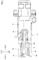
FIG. 2 is a plan view illustrating the outer column as seen from the above. -
FIG. 3 is an enlarged side view of a main portion of the outer column. -
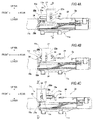
FIG. 4A is an enlarged side view of a main portion showing a positional relation between supporting plate members and sandwiched portions in a state where a steering wheel is located at a front end position of an adjustable range,FIG. 4B is an enlarged side view of the main portion showing the positional relation in a state where the steering wheel is located at a middle position, andFIG. 4C is an enlarged side view of the main portion showing the positional relation in a state where the steering wheel is located at a rear end position. -
FIG. 5A is a cross-sectional view along a line IV-IV ofFIG. 4A , andFIG. 5B is a cross-sectional view along a line IV'-IV' ofFIG. 4B . -
FIG. 6 is a view similar toFIG. 2 and illustrates another example of a shape of a slit. -
FIG. 7 is a view similar toFIG. 3 and illustrates a second embodiment of the present invention. -
FIG. 8 is a view similar toFIG. 3 and illustrates a third embodiment of the present invention. -
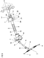
FIG. 9 is a partial sectional side view illustrating an example of a known vehicle steering device. -
FIG. 10 is a cross-sectional view illustrating an example of a conventional structure of a position adjusting mechanism of a steering wheel. -
FIGS. 1 to 5 show a first embodiment of the present invention. The present invention as well as the present embodiment is characterized by a structure capable of stabilizing a force necessary for operating an adjustment lever 25 (seeFIG. 10 ) (an operation force on the adjustment lever 25) (capable of reducing change of the operation force on the adjustment lever 25), regardless of a position of a steering wheel 4 (seeFIG. 9 ) in a front-rear direction. - The structure and operation of the other part are similar to those in the above described existing structure, and thus repeated drawings and descriptions will be omitted or simplified. Hereinafter, characteristic parts of the present invention will be mainly described.
- In the present embodiment, an
outer column 11a includes a mainouter column body 38 formed in a substantially cylindrical overall shape, and a pair of sandwichedportions side bracket 18a. The mainouter column body 38 is formed with aslit 19a in an upper surface of a front portion thereof (the left side ofFIGS. 1 to 4 ) to have a substantial T shape as seen from a radial direction. Theslit 19a is formed in order to reduce rigidity in the radial direction of the front portion of the mainouter column body 38 for sufficiently increasing a contact pressure between an inner circumferential surface of the front portion of the mainouter column body 38 and an outer circumferential surface of a rear portion of aninner column 10a according to an operation on theadjustment lever 25. Theslit 19a includes amain slit portion 33 long in an axial direction, asub slit portion 34 and a width-enlargedportion 35. Themain slit portion 33 is formed between the sandwichedportions outer column 11a. The sub slitportion 34 is formed to extend in a circumferential direction in the front end portion of themain slit portion 33 such that a front end portion of themain slit portion 33 is connected to a center portion of the sub slit portion in the circumferential direction (such that the front end portion of themain slit portion 33 is opened to the center portion of the sub slit portion in the circumferential direction). The width-enlargedportion 35 is formed in a rear end portion of themain slit portion 33 in a substantially circular shape as seen from the radial direction such that the rear end portion of themain slit portion 33 is connected to a center portion of the width-enlarged portion in the circumferential direction (such that the rear end portion of themain slit portion 33 is opened to the center portion of the width-enlarged portion in the circumferential direction). However, as shown inFIG. 6 , without forming thesub slit portion 34, a front end portion of aslit 19a may be opened to a front edge of theouter column 11a. - The sandwiched
portions outer column body 38 on an outer circumferential surface of the mainouter column body 38 at positions interposing themain slit portion 33 of theslit 19a therebetween in the width direction (the circumferential direction) and extend in parallel with each other. However, the sandwichedportions portions long holes outer column 11 a at positions which match each other. - Further, in the present embodiment, in rear end side portions of the outer surfaces of the sandwiched
portions adjustment rod 24 is located), dentedportions portions outer column body 38 side in the vertical direction). That is, the width dimension of a rear end side portion of the column-side bracket 18a configured by the sandwichedportions portions - Between the sandwiched surfaces (outer surfaces) of the sandwiched
portions portions portions 39a in a rear side of the front-rearlong hole 21a, and there is formed a steppedportion 39b in a column-center side of the front-rearlong hole 21a. The steppedportions long holes long holes portions - Further, the stepped
portion 39a which is formed between the dentedportions portions long holes - The rear portion of the
inner column 10a is internally fitted in the front portion of theouter column 11a as described above to be able to be displaced in the axial direction, accordingly, atelescopic steering column 2a is configured. Further, the middle portion of thesteering column 2a is supported on avehicle body 1 through a supportingbracket 17a (seeFIG. 9 ). The supportingbracket 17a is formed by bending a metal plate, such as a steel plate, capable of ensuring necessary strength and rigidity in a substantially U shape, and includes a mountingplate member 37 for supporting on the vehicle body, and a pair of supportingplate members plate member 37 and parallel to each other in the width direction. In a state where the sandwichedportions plate members adjustment rod 24 is inserted through the verticallong holes plate members long holes cam device 26 and thenut 29 shown inFIG. 10 ) incorporated in theadjustment rod 24 makes it possible to expand or contract the interval between the supportingplate members outer column 11 in the vertical direction and the front-rear direction and holding theouter column 11 at the adjusted position. - According to the telescopic steering column device of the present embodiment as described above, regardless of the position of the steering wheel 4 in the front-rear direction, it is possible to reduce change of a force necessary for operating the adjustment lever 25 (see
FIG. 9 ). The reason will be described below. - As shown in
FIG. 4A , in a state where the steering wheel 4 is moved to the front end position of the adjustable range (a state where theadjustment rod 24 is engaged with the rear end portions of the front-rearlong holes plate members bracket 17a are located on both sides in the width direction of the rear end portion of theslit 19a having relatively high rigidity in theouter column 11a. In this state, if theadjustment lever 25 is operated to reduce the interval between the supportingplate members plate members portions portions portions portions plate members adjustment lever 25, the supportingplate members - Therefore, in the present embodiment, in a case of elastically deforming the vicinity of the rear end portion of the
slit 19a having relatively high rigidity in themain slit portion 33 in order to reduce its diameter, it is possible to lengthen a distance L1 from a portion which is a fulcrum of the elastic deformation (seeFIG. 5A , a portion O of the mainouter column body 38 which is an intersection between the mainouter column body 38 and a virtual line perpendicular to the center axis of theouter column 11a and extending in a horizontal direction) to a force point F1 (seeFIG. 5A ) which is the lower end portion of the contact portion between the outer surface of the sandwichedportions plate members plate members portions outer column body 38. As a result, even in a case of elastically deforming the vicinity of the rear end portion of theslit 19a having relatively high rigidity in the mainouter column body 38, it is possible to suppress a force necessary for operating theadjustment lever 25 from needlessly increasing. - On the other hand, as shown in
FIG. 4C , in a state where the steering wheel 4 is moved to the rear end position of the adjustable range (a state where theadjustment rod 24 is engaged with the front end portions of the front-rearlong holes FIG. 5B ) to a force point F2 (seeFIG. 5B ) which is the lower end portion of the contact portion between the outer surface of the sandwichedportions plate members FIG. 4B , in a state where the steering wheel 4 is moved to the center position of the adjustable range (a state where theadjustment rod 24 is engaged with the middle portion of the front-rearlong holes portions plate members slit 19a having relatively low rigidity in the mainouter column body 38, a distance between a fulcrum of the elastic deformation and a force point is the same as that in the case of the existing structure. Therefore, regardless of the position of the steering wheel 4 in the front-rear direction, it is possible to stabilize a force necessary for operating theadjustment lever 25. - In the present embodiment, since the front-rear
long holes portions plate members portions adjustment lever 25, and a force necessary for operating theadjustment lever 25 is easily decreased. - Especially, since the stepped
portion 39a which is formed between the dentedportions portions long holes adjustment lever 25. -
FIG. 7 shows a second embodiment of the present invention. In anouter column 11b according to the present invention, at a lower half portion of the rear end side portion of the outer surface of a pair of sandwichedportions portions 36a is formed such that its dimension in the vertical direction increases as proceeding toward the rear side. That is, stepped portions 39 which are formed between the dentedportions portions portions - In the case of the present embodiment as described above, since it is possible to increase the distance from the position of a force point F of a force acting from the inner surfaces of the pair of supporting
plate members FIGS. 4 to 5 ) to the fulcrum O as the steering wheel 4 is displaced toward the rear side, it is possible to make even a force necessary for operating the adjustment lever 25 (seeFIG. 9 ). - The configuration and operation of the other parts are the same as those of the above-described first embodiment, and thus repeated drawings and descriptions are omitted.
-
FIG. 8 shows a third embodiment of the present invention. As shown inFIG. 8 , a pair of sandwichedportions 20a is thickened upward as proceeding toward the rear side of the vehicle body which is the right side ofFIG. 8 , and the vertical dimension of the sandwichedportion 20a is larger at a rear end side portion of the mainouter column body 38 than at a front end side portion thereof. - The configuration and operation of the other parts are the same as those of the above described first embodiment, and thus repeated drawings and descriptions are omitted.
- In the
outer column 11a shown inFIG. 1 , since the side where theslit 19a and the pair of sandwichedportions outer column 11a, the other side can be referred to as the rear side. This is also applicable toFIGS. 7 and 8 . - In the present invention, it is essential to implement a telescopic steering device for adjusting a position of a steering wheel in the front-rear direction. However, it is optional to implement a tilt steering device for adjusting the position of a steering wheel together with the telescopic steering device.
- Further, the relation between the upper side and lower side of the steering column in the vertical direction may be reverse to that of the above-described embodiments. That is, the slit and the pair of sandwiched portions may be provided on the lower side of the outer column.
- However, in order to ensure a space around knees of a driver, it is preferable that the sandwiched portions be provided on the upper side from a center axis in the axial direction (the center axis in the front-rear direction) of the main column body.
- Also, the dented portion may be formed only in the outer surface of either one sandwiched portion of the pair of sandwiched portions.
- This application is based on Japanese Patent Application No.
2014-040344, filed March 3, 2014 2014-143054, filed July 11, 2014 -
- 1:
- vehicle body
- 2, 2a:
- steering column
- 3:
- steering shaft
- 4:
- steering wheel
- 5a, 5b:
- universal joint
- 6:
- intermediate shaft
- 7:
- steering gear unit
- 8:
- input shaft
- 9:
- tie rod
- 10, 10a:
- inner column
- 11, 11a, 11b:
- outer column
- 12:
- outer tube
- 13:
- inner shaft
- 14:
- electric motor
- 15:
- housing
- 16:
- horizontal shaft
- 17, 17a:
- supporting bracket
- 18, 18a:
- column-side bracket
- 19, 19a:
- slit
- 20, 20a, 20b:
- sandwiched portion
- 21:
- front-rear long hole
- 22, 22a:
- supporting plate member
- 23:
- vertical long hole
- 24:
- adjustment rod
- 25:
- adjustment lever
- 26:
- cam device
- 27:
- drive-side cam
- 28:
- driven-side cam
- 29:
- nut
- 30:
- thrust bearing
- 31:
- pressing plate
- 32:
- engaging piece
- 33:
- main slit portion
- 34:
- sub slit portion
- 35:
- width-enlarged portion
- 36,
- 36a: dented portion
- 37:
- mounting plate member
- 38:
- main outer column body
Claims (6)
- An outer column for a telescopic steering device, the outer column comprising:a main column body which is formed in a substantially cylindrical overall shape and has a slit formed long in an axial direction at a front portion thereof; anda pair of sandwiched portions which are fixedly provided on the main column body to protrude upward or downward at positions interposing the slit therebetween in a width direction,wherein a pair of front-rear long holes are formed long in a front-rear direction on the sandwiched portions at positions matching with each other, andwherein in a rear end side portion of an outer surface of at least one sandwiched portion of the sandwiched portions, a dented portion is formed to be dented inward in the width direction at a position on a main column body side in a vertical direction.
- The outer column for the telescopic steering device according to claim 1,
wherein the dented portion is continuous to the front-rear long hole. - The outer column for the telescopic steering device according to claim 1 or 2,
wherein a stepped portion formed between the dented portion and the sandwiched portion is formed to an opposite side to the main column body side with respect to a center position of the front-rear long hole in the vertical direction. - The outer column for the telescopic steering device according to any one of claims 1 to 3,
wherein a vertical dimension of the dented portion increases as proceeding toward a rear side. - The outer column for the telescopic steering device according to any one of claims 1 to 4,
wherein a vertical dimension of the sandwiched portions is larger at a rear end side portion of the main column body than at a front end side portion of the main column body. - A telescopic steering device comprising:a steering column which includes an inner column and an outer column, the outer column being externally fitted on a rear portion of the inner column and having a slit formed on a front portion thereof which is a fitting portion with the inner column such that an inner diameter of the front portion can be expanded or contracted based on the slit;a supporting bracket which includes a pair of supporting plate members which sandwich a pair of sandwiched portions of the outer column from both sides in a width direction, and a mounting plate member which supports the supporting plate members to a vehicle body, wherein the supporting plate members are formed with bracket-side through holes at a position which matches with front-rear long holes formed long in a front-rear direction on the sandwiched portions;a rod member which is inserted through the front-rear long holes and the bracket-side through holes; andan adjustment mechanism which is configured to expand or contract an interval between a pair of pressing members provided at both end portions of the rod member based on an operation on an adjustment lever provided at an end portion of the rod member, wherein when the interval is contracted, an interval between inner surfaces of the supporting plate members is contracted, whereby the inner surfaces of the supporting plate members and outer surfaces of the sandwiched portions are frictionally engaged such that a position of the outer column in the front-rear direction with respect to the inner column is fixed,wherein the outer column is the outer column according to claim 1 or 2.
Applications Claiming Priority (3)
| Application Number | Priority Date | Filing Date | Title |
|---|---|---|---|
| JP2014040344 | 2014-03-03 | ||
| JP2014143054 | 2014-07-11 | ||
| PCT/JP2014/080981 WO2015133017A1 (en) | 2014-03-03 | 2014-11-21 | Outer column for telescopic steering device, and telescopic steering device |
Publications (3)
| Publication Number | Publication Date |
|---|---|
| EP3081454A1 true EP3081454A1 (en) | 2016-10-19 |
| EP3081454A4 EP3081454A4 (en) | 2017-03-29 |
| EP3081454B1 EP3081454B1 (en) | 2018-05-02 |
Family
ID=54054840
Family Applications (1)
| Application Number | Title | Priority Date | Filing Date |
|---|---|---|---|
| EP14885019.1A Not-in-force EP3081454B1 (en) | 2014-03-03 | 2014-11-21 | Outer column for telescopic steering device, and telescopic steering device |
Country Status (5)
| Country | Link |
|---|---|
| US (1) | US9828018B2 (en) |
| EP (1) | EP3081454B1 (en) |
| JP (1) | JP6447622B2 (en) |
| CN (1) | CN105813919B (en) |
| WO (1) | WO2015133017A1 (en) |
Families Citing this family (9)
| Publication number | Priority date | Publication date | Assignee | Title |
|---|---|---|---|---|
| WO2015133017A1 (en) * | 2014-03-03 | 2015-09-11 | 日本精工株式会社 | Outer column for telescopic steering device, and telescopic steering device |
| US10093340B2 (en) * | 2015-05-19 | 2018-10-09 | Nsk Ltd. | Steering device |
| EP3257722B1 (en) * | 2015-05-19 | 2019-03-27 | NSK Ltd. | Steering device |
| US11046564B2 (en) | 2015-11-09 | 2021-06-29 | Crown Equipment Corporation | Order picker materials handling vehicle with improved downward visibility when driving elevated |
| JP2017197141A (en) * | 2016-04-28 | 2017-11-02 | 株式会社ジェイテクト | Steering device |
| JP6760626B2 (en) * | 2017-05-10 | 2020-09-23 | 株式会社ジェイテクト | Steering device |
| JP7484323B2 (en) * | 2020-03-30 | 2024-05-16 | 日本精工株式会社 | Steering system |
| EP4524085A3 (en) | 2020-06-05 | 2025-05-28 | Crown Equipment Corporation | Viewing windows in a materials handling vehicle |
| JP7846561B2 (en) * | 2022-05-23 | 2026-04-15 | Nskステアリング&コントロール株式会社 | Steering system |
Family Cites Families (24)
| Publication number | Priority date | Publication date | Assignee | Title |
|---|---|---|---|---|
| US8505407B2 (en) | 2004-07-27 | 2013-08-13 | Nsk Ltd. | Steering column device |
| JP5076673B2 (en) * | 2006-12-15 | 2012-11-21 | 日本精工株式会社 | Steering device |
| US8091449B2 (en) | 2006-12-15 | 2012-01-10 | Nsk Ltd. | Steering apparatus |
| JP2008174105A (en) | 2007-01-18 | 2008-07-31 | Nsk Ltd | Steering device |
| JP2008302751A (en) * | 2007-06-06 | 2008-12-18 | Nsk Ltd | Steering column device |
| DE112008003076B4 (en) * | 2007-11-13 | 2019-06-19 | Nsk Ltd. | steering device |
| JP5279741B2 (en) * | 2009-03-30 | 2013-09-04 | 株式会社山田製作所 | Steering device |
| JP5273089B2 (en) * | 2009-05-22 | 2013-08-28 | 日本精工株式会社 | Steering device |
| KR20110096805A (en) * | 2010-02-23 | 2011-08-31 | 주식회사 만도 | Steering column of automobile and steering apparatus of automobile including same |
| JP5429109B2 (en) * | 2010-08-20 | 2014-02-26 | 日本精工株式会社 | Steering device |
| JP5429110B2 (en) * | 2010-08-20 | 2014-02-26 | 日本精工株式会社 | Steering device |
| JP5620840B2 (en) * | 2011-02-04 | 2014-11-05 | 株式会社山田製作所 | Steering device |
| JP5464182B2 (en) * | 2011-02-25 | 2014-04-09 | 日本精工株式会社 | Telescopic steering device |
| WO2012114812A1 (en) * | 2011-02-25 | 2012-08-30 | 日本精工株式会社 | Steering column device |
| JP5609838B2 (en) * | 2011-06-16 | 2014-10-22 | 日本精工株式会社 | Steering column device |
| JP5561253B2 (en) * | 2011-07-20 | 2014-07-30 | 日本精工株式会社 | Steering device |
| JP5494587B2 (en) * | 2011-08-01 | 2014-05-14 | 日本精工株式会社 | Telescopic steering device |
| EP2899096B1 (en) * | 2013-01-15 | 2017-07-26 | NSK Ltd. | Tilt-type steering device |
| US9254860B2 (en) * | 2013-02-13 | 2016-02-09 | Nsk Ltd. | Outer column and steering column apparatus |
| JP5804211B2 (en) * | 2013-04-03 | 2015-11-04 | 日本精工株式会社 | Telescopic steering device and outer column |
| EP2982568B1 (en) * | 2013-04-03 | 2017-08-23 | NSK Ltd. | Outer column to be used in telescopic steering device |
| WO2014175224A1 (en) * | 2013-04-26 | 2014-10-30 | 日本精工株式会社 | Telescopic steering device |
| US9604661B2 (en) * | 2013-12-30 | 2017-03-28 | Nsk Ltd. | Steering column apparatus |
| WO2015133017A1 (en) * | 2014-03-03 | 2015-09-11 | 日本精工株式会社 | Outer column for telescopic steering device, and telescopic steering device |
-
2014
- 2014-11-21 WO PCT/JP2014/080981 patent/WO2015133017A1/en not_active Ceased
- 2014-11-21 EP EP14885019.1A patent/EP3081454B1/en not_active Not-in-force
- 2014-11-21 US US15/102,595 patent/US9828018B2/en not_active Expired - Fee Related
- 2014-11-21 JP JP2016506082A patent/JP6447622B2/en active Active
- 2014-11-21 CN CN201480067102.3A patent/CN105813919B/en not_active Expired - Fee Related
Also Published As
| Publication number | Publication date |
|---|---|
| US9828018B2 (en) | 2017-11-28 |
| EP3081454A4 (en) | 2017-03-29 |
| EP3081454B1 (en) | 2018-05-02 |
| CN105813919A (en) | 2016-07-27 |
| CN105813919B (en) | 2018-02-06 |
| JP6447622B2 (en) | 2019-01-09 |
| JPWO2015133017A1 (en) | 2017-04-06 |
| WO2015133017A1 (en) | 2015-09-11 |
| US20160318541A1 (en) | 2016-11-03 |
Similar Documents
| Publication | Publication Date | Title |
|---|---|---|
| EP3081454B1 (en) | Outer column for telescopic steering device, and telescopic steering device | |
| JP5787036B2 (en) | Outer column | |
| JP5070795B2 (en) | Steering wheel position adjustment device | |
| EP2899096B1 (en) | Tilt-type steering device | |
| US20130160595A1 (en) | Steering column apparatus | |
| JP5737456B2 (en) | Steering column and telescopic steering device | |
| EP2724916B1 (en) | Tilt steering column device | |
| EP3315380A1 (en) | Position adjusting apparatus for steering wheel | |
| JP6379863B2 (en) | Steering wheel position adjusting device and manufacturing method thereof | |
| JP2016047669A5 (en) | ||
| US11511788B2 (en) | Steering column and steering device | |
| US11447170B2 (en) | Steering column and steering device | |
| JP2015131518A (en) | Position adjustment device of steering wheel | |
| JP6406020B2 (en) | Steering wheel position adjustment device | |
| JP2015061775A (en) | Telescopic steering device | |
| JP2015214319A (en) | Telescopic steering device |
Legal Events
| Date | Code | Title | Description |
|---|---|---|---|
| PUAI | Public reference made under article 153(3) epc to a published international application that has entered the european phase |
Free format text: ORIGINAL CODE: 0009012 |
|
| 17P | Request for examination filed |
Effective date: 20160614 |
|
| AK | Designated contracting states |
Kind code of ref document: A1 Designated state(s): AL AT BE BG CH CY CZ DE DK EE ES FI FR GB GR HR HU IE IS IT LI LT LU LV MC MK MT NL NO PL PT RO RS SE SI SK SM TR |
|
| AX | Request for extension of the european patent |
Extension state: BA ME |
|
| A4 | Supplementary search report drawn up and despatched |
Effective date: 20170224 |
|
| RIC1 | Information provided on ipc code assigned before grant |
Ipc: B62D 1/185 20060101ALI20170220BHEP Ipc: B62D 1/184 20060101AFI20170220BHEP |
|
| DAX | Request for extension of the european patent (deleted) | ||
| GRAP | Despatch of communication of intention to grant a patent |
Free format text: ORIGINAL CODE: EPIDOSNIGR1 |
|
| INTG | Intention to grant announced |
Effective date: 20171206 |
|
| RIN1 | Information on inventor provided before grant (corrected) |
Inventor name: MIHARA, SHIN Inventor name: MURATA, RYOTA Inventor name: WATANABE, MASAJIROU |
|
| GRAJ | Information related to disapproval of communication of intention to grant by the applicant or resumption of examination proceedings by the epo deleted |
Free format text: ORIGINAL CODE: EPIDOSDIGR1 |
|
| GRAL | Information related to payment of fee for publishing/printing deleted |
Free format text: ORIGINAL CODE: EPIDOSDIGR3 |
|
| GRAS | Grant fee paid |
Free format text: ORIGINAL CODE: EPIDOSNIGR3 |
|
| GRAR | Information related to intention to grant a patent recorded |
Free format text: ORIGINAL CODE: EPIDOSNIGR71 |
|
| GRAA | (expected) grant |
Free format text: ORIGINAL CODE: 0009210 |
|
| AK | Designated contracting states |
Kind code of ref document: B1 Designated state(s): AL AT BE BG CH CY CZ DE DK EE ES FI FR GB GR HR HU IE IS IT LI LT LU LV MC MK MT NL NO PL PT RO RS SE SI SK SM TR |
|
| INTG | Intention to grant announced |
Effective date: 20180327 |
|
| REG | Reference to a national code |
Ref country code: GB Ref legal event code: FG4D |
|
| REG | Reference to a national code |
Ref country code: CH Ref legal event code: EP Ref country code: AT Ref legal event code: REF Ref document number: 994895 Country of ref document: AT Kind code of ref document: T Effective date: 20180515 |
|
| REG | Reference to a national code |
Ref country code: DE Ref legal event code: R096 Ref document number: 602014025078 Country of ref document: DE Ref country code: IE Ref legal event code: FG4D |
|
| REG | Reference to a national code |
Ref country code: DE Ref legal event code: R096 Ref document number: 602014025078 Country of ref document: DE |
|
| REG | Reference to a national code |
Ref country code: NL Ref legal event code: MP Effective date: 20180502 |
|
| REG | Reference to a national code |
Ref country code: LT Ref legal event code: MG4D |
|
| PG25 | Lapsed in a contracting state [announced via postgrant information from national office to epo] |
Ref country code: FI Free format text: LAPSE BECAUSE OF FAILURE TO SUBMIT A TRANSLATION OF THE DESCRIPTION OR TO PAY THE FEE WITHIN THE PRESCRIBED TIME-LIMIT Effective date: 20180502 Ref country code: BG Free format text: LAPSE BECAUSE OF FAILURE TO SUBMIT A TRANSLATION OF THE DESCRIPTION OR TO PAY THE FEE WITHIN THE PRESCRIBED TIME-LIMIT Effective date: 20180802 Ref country code: LT Free format text: LAPSE BECAUSE OF FAILURE TO SUBMIT A TRANSLATION OF THE DESCRIPTION OR TO PAY THE FEE WITHIN THE PRESCRIBED TIME-LIMIT Effective date: 20180502 Ref country code: ES Free format text: LAPSE BECAUSE OF FAILURE TO SUBMIT A TRANSLATION OF THE DESCRIPTION OR TO PAY THE FEE WITHIN THE PRESCRIBED TIME-LIMIT Effective date: 20180502 Ref country code: NO Free format text: LAPSE BECAUSE OF FAILURE TO SUBMIT A TRANSLATION OF THE DESCRIPTION OR TO PAY THE FEE WITHIN THE PRESCRIBED TIME-LIMIT Effective date: 20180802 Ref country code: SE Free format text: LAPSE BECAUSE OF FAILURE TO SUBMIT A TRANSLATION OF THE DESCRIPTION OR TO PAY THE FEE WITHIN THE PRESCRIBED TIME-LIMIT Effective date: 20180502 |
|
| PG25 | Lapsed in a contracting state [announced via postgrant information from national office to epo] |
Ref country code: NL Free format text: LAPSE BECAUSE OF FAILURE TO SUBMIT A TRANSLATION OF THE DESCRIPTION OR TO PAY THE FEE WITHIN THE PRESCRIBED TIME-LIMIT Effective date: 20180502 Ref country code: RS Free format text: LAPSE BECAUSE OF FAILURE TO SUBMIT A TRANSLATION OF THE DESCRIPTION OR TO PAY THE FEE WITHIN THE PRESCRIBED TIME-LIMIT Effective date: 20180502 Ref country code: HR Free format text: LAPSE BECAUSE OF FAILURE TO SUBMIT A TRANSLATION OF THE DESCRIPTION OR TO PAY THE FEE WITHIN THE PRESCRIBED TIME-LIMIT Effective date: 20180502 Ref country code: GR Free format text: LAPSE BECAUSE OF FAILURE TO SUBMIT A TRANSLATION OF THE DESCRIPTION OR TO PAY THE FEE WITHIN THE PRESCRIBED TIME-LIMIT Effective date: 20180803 Ref country code: LV Free format text: LAPSE BECAUSE OF FAILURE TO SUBMIT A TRANSLATION OF THE DESCRIPTION OR TO PAY THE FEE WITHIN THE PRESCRIBED TIME-LIMIT Effective date: 20180502 |
|
| REG | Reference to a national code |
Ref country code: AT Ref legal event code: MK05 Ref document number: 994895 Country of ref document: AT Kind code of ref document: T Effective date: 20180502 |
|
| PG25 | Lapsed in a contracting state [announced via postgrant information from national office to epo] |
Ref country code: SK Free format text: LAPSE BECAUSE OF FAILURE TO SUBMIT A TRANSLATION OF THE DESCRIPTION OR TO PAY THE FEE WITHIN THE PRESCRIBED TIME-LIMIT Effective date: 20180502 Ref country code: PL Free format text: LAPSE BECAUSE OF FAILURE TO SUBMIT A TRANSLATION OF THE DESCRIPTION OR TO PAY THE FEE WITHIN THE PRESCRIBED TIME-LIMIT Effective date: 20180502 Ref country code: CZ Free format text: LAPSE BECAUSE OF FAILURE TO SUBMIT A TRANSLATION OF THE DESCRIPTION OR TO PAY THE FEE WITHIN THE PRESCRIBED TIME-LIMIT Effective date: 20180502 Ref country code: AT Free format text: LAPSE BECAUSE OF FAILURE TO SUBMIT A TRANSLATION OF THE DESCRIPTION OR TO PAY THE FEE WITHIN THE PRESCRIBED TIME-LIMIT Effective date: 20180502 Ref country code: RO Free format text: LAPSE BECAUSE OF FAILURE TO SUBMIT A TRANSLATION OF THE DESCRIPTION OR TO PAY THE FEE WITHIN THE PRESCRIBED TIME-LIMIT Effective date: 20180502 Ref country code: DK Free format text: LAPSE BECAUSE OF FAILURE TO SUBMIT A TRANSLATION OF THE DESCRIPTION OR TO PAY THE FEE WITHIN THE PRESCRIBED TIME-LIMIT Effective date: 20180502 Ref country code: EE Free format text: LAPSE BECAUSE OF FAILURE TO SUBMIT A TRANSLATION OF THE DESCRIPTION OR TO PAY THE FEE WITHIN THE PRESCRIBED TIME-LIMIT Effective date: 20180502 |
|
| REG | Reference to a national code |
Ref country code: DE Ref legal event code: R097 Ref document number: 602014025078 Country of ref document: DE |
|
| PG25 | Lapsed in a contracting state [announced via postgrant information from national office to epo] |
Ref country code: SM Free format text: LAPSE BECAUSE OF FAILURE TO SUBMIT A TRANSLATION OF THE DESCRIPTION OR TO PAY THE FEE WITHIN THE PRESCRIBED TIME-LIMIT Effective date: 20180502 Ref country code: IT Free format text: LAPSE BECAUSE OF FAILURE TO SUBMIT A TRANSLATION OF THE DESCRIPTION OR TO PAY THE FEE WITHIN THE PRESCRIBED TIME-LIMIT Effective date: 20180502 |
|
| PLBE | No opposition filed within time limit |
Free format text: ORIGINAL CODE: 0009261 |
|
| STAA | Information on the status of an ep patent application or granted ep patent |
Free format text: STATUS: NO OPPOSITION FILED WITHIN TIME LIMIT |
|
| 26N | No opposition filed |
Effective date: 20190205 |
|
| PG25 | Lapsed in a contracting state [announced via postgrant information from national office to epo] |
Ref country code: SI Free format text: LAPSE BECAUSE OF FAILURE TO SUBMIT A TRANSLATION OF THE DESCRIPTION OR TO PAY THE FEE WITHIN THE PRESCRIBED TIME-LIMIT Effective date: 20180502 |
|
| REG | Reference to a national code |
Ref country code: CH Ref legal event code: PL |
|
| GBPC | Gb: european patent ceased through non-payment of renewal fee |
Effective date: 20181121 |
|
| PG25 | Lapsed in a contracting state [announced via postgrant information from national office to epo] |
Ref country code: MC Free format text: LAPSE BECAUSE OF FAILURE TO SUBMIT A TRANSLATION OF THE DESCRIPTION OR TO PAY THE FEE WITHIN THE PRESCRIBED TIME-LIMIT Effective date: 20180502 Ref country code: LU Free format text: LAPSE BECAUSE OF NON-PAYMENT OF DUE FEES Effective date: 20181121 |
|
| REG | Reference to a national code |
Ref country code: BE Ref legal event code: MM Effective date: 20181130 |
|
| REG | Reference to a national code |
Ref country code: IE Ref legal event code: MM4A |
|
| PG25 | Lapsed in a contracting state [announced via postgrant information from national office to epo] |
Ref country code: LI Free format text: LAPSE BECAUSE OF NON-PAYMENT OF DUE FEES Effective date: 20181130 Ref country code: CH Free format text: LAPSE BECAUSE OF NON-PAYMENT OF DUE FEES Effective date: 20181130 |
|
| PG25 | Lapsed in a contracting state [announced via postgrant information from national office to epo] |
Ref country code: FR Free format text: LAPSE BECAUSE OF NON-PAYMENT OF DUE FEES Effective date: 20181130 Ref country code: IE Free format text: LAPSE BECAUSE OF NON-PAYMENT OF DUE FEES Effective date: 20181121 |
|
| PG25 | Lapsed in a contracting state [announced via postgrant information from national office to epo] |
Ref country code: BE Free format text: LAPSE BECAUSE OF NON-PAYMENT OF DUE FEES Effective date: 20181130 Ref country code: AL Free format text: LAPSE BECAUSE OF FAILURE TO SUBMIT A TRANSLATION OF THE DESCRIPTION OR TO PAY THE FEE WITHIN THE PRESCRIBED TIME-LIMIT Effective date: 20180502 |
|
| PG25 | Lapsed in a contracting state [announced via postgrant information from national office to epo] |
Ref country code: GB Free format text: LAPSE BECAUSE OF NON-PAYMENT OF DUE FEES Effective date: 20181121 |
|
| PG25 | Lapsed in a contracting state [announced via postgrant information from national office to epo] |
Ref country code: MT Free format text: LAPSE BECAUSE OF NON-PAYMENT OF DUE FEES Effective date: 20181121 |
|
| PGFP | Annual fee paid to national office [announced via postgrant information from national office to epo] |
Ref country code: DE Payment date: 20191105 Year of fee payment: 6 |
|
| PG25 | Lapsed in a contracting state [announced via postgrant information from national office to epo] |
Ref country code: TR Free format text: LAPSE BECAUSE OF FAILURE TO SUBMIT A TRANSLATION OF THE DESCRIPTION OR TO PAY THE FEE WITHIN THE PRESCRIBED TIME-LIMIT Effective date: 20180502 |
|
| PG25 | Lapsed in a contracting state [announced via postgrant information from national office to epo] |
Ref country code: PT Free format text: LAPSE BECAUSE OF FAILURE TO SUBMIT A TRANSLATION OF THE DESCRIPTION OR TO PAY THE FEE WITHIN THE PRESCRIBED TIME-LIMIT Effective date: 20180502 |
|
| PG25 | Lapsed in a contracting state [announced via postgrant information from national office to epo] |
Ref country code: HU Free format text: LAPSE BECAUSE OF FAILURE TO SUBMIT A TRANSLATION OF THE DESCRIPTION OR TO PAY THE FEE WITHIN THE PRESCRIBED TIME-LIMIT; INVALID AB INITIO Effective date: 20141121 Ref country code: MK Free format text: LAPSE BECAUSE OF NON-PAYMENT OF DUE FEES Effective date: 20180502 Ref country code: CY Free format text: LAPSE BECAUSE OF FAILURE TO SUBMIT A TRANSLATION OF THE DESCRIPTION OR TO PAY THE FEE WITHIN THE PRESCRIBED TIME-LIMIT Effective date: 20180502 |
|
| PG25 | Lapsed in a contracting state [announced via postgrant information from national office to epo] |
Ref country code: IS Free format text: LAPSE BECAUSE OF FAILURE TO SUBMIT A TRANSLATION OF THE DESCRIPTION OR TO PAY THE FEE WITHIN THE PRESCRIBED TIME-LIMIT Effective date: 20180902 |
|
| REG | Reference to a national code |
Ref country code: DE Ref legal event code: R119 Ref document number: 602014025078 Country of ref document: DE |
|
| PG25 | Lapsed in a contracting state [announced via postgrant information from national office to epo] |
Ref country code: DE Free format text: LAPSE BECAUSE OF NON-PAYMENT OF DUE FEES Effective date: 20210601 |