EP3081449B1 - Construction de plancher pour un véhicule - Google Patents
Construction de plancher pour un véhicule Download PDFInfo
- Publication number
- EP3081449B1 EP3081449B1 EP16154928.2A EP16154928A EP3081449B1 EP 3081449 B1 EP3081449 B1 EP 3081449B1 EP 16154928 A EP16154928 A EP 16154928A EP 3081449 B1 EP3081449 B1 EP 3081449B1
- Authority
- EP
- European Patent Office
- Prior art keywords
- planks
- floor
- vehicle according
- vehicle
- extending
- Prior art date
- Legal status (The legal status is an assumption and is not a legal conclusion. Google has not performed a legal analysis and makes no representation as to the accuracy of the status listed.)
- Active
Links
- 238000010276 construction Methods 0.000 title description 2
- 239000011162 core material Substances 0.000 claims description 25
- 239000000463 material Substances 0.000 claims description 16
- 238000000034 method Methods 0.000 claims description 14
- 238000009408 flooring Methods 0.000 claims description 12
- 229920005989 resin Polymers 0.000 claims description 12
- 239000011347 resin Substances 0.000 claims description 12
- 239000002131 composite material Substances 0.000 claims description 9
- 238000005520 cutting process Methods 0.000 claims description 6
- XLYOFNOQVPJJNP-UHFFFAOYSA-N water Substances O XLYOFNOQVPJJNP-UHFFFAOYSA-N 0.000 claims description 3
- 239000000853 adhesive Substances 0.000 claims description 2
- 230000001070 adhesive effect Effects 0.000 claims description 2
- 239000012783 reinforcing fiber Substances 0.000 claims description 2
- 238000004519 manufacturing process Methods 0.000 description 4
- 238000000465 moulding Methods 0.000 description 4
- 238000005253 cladding Methods 0.000 description 3
- 239000000835 fiber Substances 0.000 description 3
- 229920001296 polysiloxane Polymers 0.000 description 3
- 229910000831 Steel Inorganic materials 0.000 description 2
- 230000008878 coupling Effects 0.000 description 2
- 238000010168 coupling process Methods 0.000 description 2
- 238000005859 coupling reaction Methods 0.000 description 2
- 239000006260 foam Substances 0.000 description 2
- 238000010079 rubber tapping Methods 0.000 description 2
- 239000010959 steel Substances 0.000 description 2
- 229920001187 thermosetting polymer Polymers 0.000 description 2
- KXGFMDJXCMQABM-UHFFFAOYSA-N 2-methoxy-6-methylphenol Chemical compound [CH]OC1=CC=CC([CH])=C1O KXGFMDJXCMQABM-UHFFFAOYSA-N 0.000 description 1
- 229920002430 Fibre-reinforced plastic Polymers 0.000 description 1
- 230000002745 absorbent Effects 0.000 description 1
- 239000002250 absorbent Substances 0.000 description 1
- XAGFODPZIPBFFR-UHFFFAOYSA-N aluminium Chemical compound [Al] XAGFODPZIPBFFR-UHFFFAOYSA-N 0.000 description 1
- 229910052782 aluminium Inorganic materials 0.000 description 1
- 230000005540 biological transmission Effects 0.000 description 1
- 230000015572 biosynthetic process Effects 0.000 description 1
- 239000011151 fibre-reinforced plastic Substances 0.000 description 1
- 238000001802 infusion Methods 0.000 description 1
- 238000009434 installation Methods 0.000 description 1
- 239000012774 insulation material Substances 0.000 description 1
- 238000005304 joining Methods 0.000 description 1
- 238000012986 modification Methods 0.000 description 1
- 230000004048 modification Effects 0.000 description 1
- 230000000149 penetrating effect Effects 0.000 description 1
- 239000005011 phenolic resin Substances 0.000 description 1
- 229920001568 phenolic resin Polymers 0.000 description 1
- 239000004033 plastic Substances 0.000 description 1
- 229920003023 plastic Polymers 0.000 description 1
- 239000011120 plywood Substances 0.000 description 1
- 239000013589 supplement Substances 0.000 description 1
Images


Classifications
-
- B—PERFORMING OPERATIONS; TRANSPORTING
- B61—RAILWAYS
- B61D—BODY DETAILS OR KINDS OF RAILWAY VEHICLES
- B61D17/00—Construction details of vehicle bodies
- B61D17/04—Construction details of vehicle bodies with bodies of metal; with composite, e.g. metal and wood body structures
- B61D17/10—Floors
Definitions
- This invention relates to a floor construction for a vehicle particularly but not exclusively of the type which carries passengers standing or seated, such as a light rail or road transit vehicle and including other vehicles used for commercial transportation of passengers, such as a road transit vehicle, airport and hotel shuttles, converted van and truck cutaways, heavy passenger rail and light rail.
- mass transit vehicles and particularly city buses are manufactured from a welded steel frame defining a floor frame, side wall frame and roof bows which is then clad using sheet cladding material riveted, glued or otherwise fixed to the frame. Insulation material is inserted between the frame members inside the exterior cladding and outside of the interior cladding.
- the flooring is conventionally applied from individual simple rectangular panels which are arranged to span across the floor frame and fastened to the floor frame by conventional fasteners.
- the panels are arranged with butting side edges edge to edge along the vehicle.
- the floor panels are often fabricated from plywood but however composite materials are also sometimes used including flooring panels manufactured from fibre reinforced plastics material.
- One particular panel is manufactured from top and bottom sheets of a fibrous mat applied on top and bottom surfaces of a honeycomb material manufactured from phenolic resin impregnated paper with a thermosetting foam introduced into the honeycomb cores.
- the panels are formed, they are conventionally rectangular and arranged edge to edge and cut to shape and to size to complete the necessary flooring overlay.
- bus structures from fibre reinforced composite plastics material so that the side walls, roof structure and floor are each formed separately from such composite materials and are attached together to form the complete bus structure without the necessity for an additional frame supporting the structure.
- US Patent 6,375,249 (Stanton) issued April 23 2002 discloses a public transit vehicle which has a vehicle body having a roof defining an interior ceiling surface, two side walls each extending longitudinally of the vehicle including an upper side wall portion connecting to the roof and a row of windows underneath the upper portion, a central aisle and two rows of seats each on a respective side of the aisle and along the side wall at the windows.
- the roof and floor are formed from a welded frame structure over which is applied a molded panel formed in single panel structure and bonded to the frame structure.
- the panel is formed by molding a sandwich using a thermosetting resin through top and bottom fiber reinforced sheets and a honeycomb layer of resin impregnated paper and foam between the sheets.
- the floor panel is shaped so that its thickness varies and its top and bottom surfaces deviate from an otherwise planar structure to incline downwardly at a door way and to incline upwardly to clear structural elements.
- US Patent 8,006,321 (Lusk) issued November 29 2011 discloses a structural shear panel for forming a floor panel for formed by a composite of top and bottom sheets and a core with a vacuum infused resin.
- the panel is mainly planar and terminates at its side edges at a portion which lies in a common plane and portions are provided which are deformed out of the generally planar shape to form depending or elevated sections.
- the structure is formed by resin infusion into the sheets and core on a generally flat plate defining the planar panel portion with removable sections to define the depending and elevated sections. Edge pieces are attached to the plate to define the edges of the panel.
- Document EP 1 942 039 A1 discloses a structural shear panel for forming a floor panel for support by a vehicle frame.
- the panel is formed by a composite of top and bottom sheets and a core with a vacuum infused resin.
- the invention is defined by the features of claim 1.
- planks are formed solely by one center plank and two side planks. These are preferably in many cases of different lengths so that he center plank extends along a greater extent for example the whole length of the floor area and the side planks are typically shorter and are cut off at specific locations for example wheel arches.
- the invention is therefore also directed to the kit of parts defined by this set of planks which are pre-cut to the required lengths.
- This system allows preformed and pre-cut planks to be manufactured at relatively low cost and supplied to be assembled into the floor at the vehicle manufacturing plant. This avoids the necessity in the prior art to manufacture a whole floor in one piece which requires expensive tooling and difficult handling techniques.
- the invention thus provides a new concept for structural composite flooring for commercial vehicles.
- the flooring is lightweight, high strength, and is supplied in pultruded or vacuum-assisted resin transfer molded (VARTM) planks in long lengths up to for example a maximum length of 45 feet.
- VARTM vacuum-assisted resin transfer molded
- the key benefit is that unlike the unitized composite flooring currently manufactured in the prior art, the plank flooring is easier to handle and install. That is the flooring can be installed in relative ease by, for example a 4' x 28' x 3/4" centre plank down the length of the bus (or passenger rail car) chassis, and then installing the side planks whilst standing on the centre plank.
- planks can be trimmed to any length, facilitating the manufacture of buses and rail cars of varying lengths without additional tooling penalties. This is not true for the prior art arrangements of a single panel flooring.
- the planks interface along an optional, longitudinal seat rail profile which is mechanically attached to a longitudinal beam which makes up part of the vehicle's chassis.
- the planks are bonded to the seat rail.
- the seat rail is omitted.
- the planks are then reversed so that longitudinal flanges at the edges of the planks overlap, creating a leak-proof, structural joint.
- the center plank has a width to form a central aisle along which passengers can walk between the seats.
- the center plank has a width spanning a distance between two of said longitudinal rails.
- the floor frame is formed by two inner rails and two outer rails at the side edges and wherein the center plank spans the space between the inner rails and two side planks span the space between the inner rails and the outer rail where the center plank connects to the side planks at the inner rails.
- This can be at an overlap joint or may include a longitudinal support rail for supporting a seat frame member.
- the floor also may include at least one molded section extending across the floor at a position along the length of the floor against which an end of the planks abuts.
- the molded sections can include a front molded section and intermediate molded section for the floor of the vehicle which supplement the planks to define the full floor structure.
- the center plank of the planks can extend between the wheel arches and the two side planks terminate at the wheel arches.
- planks can be formed using different processes but typically will be arranged so that the planks are of constant thickness along their length and across their width.
- the planks are formed by pultrusion.
- the planks are formed by a vacuum infused resin process on a mold where the planks are formed simultaneously side by side on the mold.
- planks can be formed either by pultrusion or on the mold with side edges of part of reduced thickness to allow the formation of an overlap joint during assembly.
- the planks are formed as a common structure with the upper and lower sheets joined together at side edges to allow cutting through the sheets at right angles at the side edges to separate the planks to define the three (or more) separate planks for separate transport and installation for subsequent assembly in place.
- a part of the core can be formed of a material of higher density than other parts which can be used for mounting of components to be connected to the floor such as stanchions where the base of the stanchion is connected to the floor by self-tapping screws threaded directly into the high density material or through the higher density core portion to a tapping plate bonded underneath the floor plank.
- each of the side planks is formed of a material of higher density than other parts to allow cutting of the plank around side posts of the frame. This allows the plank to be cut thus penetrating the upper and lower sheets to the core whilst preventing the capillary intrusion of water into the core due to the use of the higher density non-absorbent core portion.
- the floor includes a front lower deck extending from a position adjacent a front wall to a transverse step and a rear upper deck extending from the transverse step to a rear wall with the transverse step between the decks, the front deck being formed from a first set of planks and the rear deck being formed from a second set of planks with a molded step section forming said transverse step therebetween.
- the front lower deck may include a downwardly inclined molded portion at a forward end thereof against which a front end of the planks abuts.
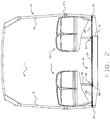
- the vehicle of the present invention can be of various different configurations and structures but generally includes a vehicle body 10 having a roof 11 two side walls 12, 13 typically including windows each extending longitudinally of the vehicle, seating rows 14 and 15 and a vehicle floor 16.
- the vehicle side walls and roof typically are formed from a frame including posts 17 and longitudinal rails 17A clad by suitable materials, often aluminum panels.
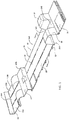
- the floor 16 has a bottom frame including a plurality of rails 18, 19, 20 and 21 with welded cross members 22 supporting a planar floor structure 23.
- the vehicle floor structure on top of the frame comprises three longitudinally extending flooring planks 24, 25 and 26 each extending along at least part of the length of the vehicle body.
- the planks are arranged side by side so as to collectively span between the side walls 12 and 13.
- the floor includes only the three planks defined by a center plank 24 and two side planks 25 and 26 of different lengths relative to the center plank 24.
- the floor includes a front lower deck 16A extending from a position adjacent a front wall to a transverse step 27 and a rear upper deck 16B extending from the transverse step 27 to a rear wall 29 with the transverse step 27 between the decks.
- the front deck 16A formed from a first set of planks 24, 25 and 26 and the rear deck 16B is elevated over the transmission and rear axle and is formed from a second set of planks 24A, 25A and 26A with the molded step section 27A forming the transverse floor section 27 therebetween.
- the planks of the lower deck are cut from the same profile as the planks of the upper deck allowing the flooring system to be manufactured easily with constant tooling.
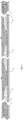
- the vehicle includes a first wheel arch 36 at one side wall for covering a first wheel and a second wheel arch 37 at a second side wall for covering a second wheel and the center plank 24 extends between the wheel arches at a portion 24B while the two side planks 25 and 26 terminate at end edges 25X, 26X the wheel arches.
- the floor frame is formed by two inner rails 19 and 20 and two outer rails 18 and 21 at the side edges.
- the center plank 24 spans the space between the inner rails 19 and 20 and the side plank 26 spans the space between the inner rail 19 and the outer rail 18 and symmetrically the plank 25 spans the space between the inner rail 20 and the outer rail 21.
- the center plank 24 has a width to form a central aisle along which passengers can walk between the seats and has a width spanning a distance between two of the longitudinal rails 19 and 20.
- the center plank 24 connects to the side planks 25 and 26 at overlapping joints 31, 32 overlying the inner rails as best shown in Figure 6 .
- the center plank 24 connects to the respective side planks at a joint which includes a longitudinal support rail 33 for supporting a seat frame member 34 of the row of seats 14, 15.
- the planks include portions 35 which overlie side parts of the rail 33.
- the planks are attached to the top surface of the underlying rails by adhesive A which also connects the planks at the rail joints.
- planks are molded as shown in Figure 6 from a composite material having an upper skin 40 and a lower skin 41 of material each including reinforcing fibers and an intervening core material layer 42 all containing a cured resin material. Materials of this type are well known and can be manufactured using different processes.
- the planks including the upper and lower sheets and the core are formed by pultrusion using well known techniques of core and fiber feeding.
- the planks 24, 25 and 26 including the upper and lower sheets and the core are formed by a vacuum infused resin (VARTM) process on a mold 45.
- VARTM vacuum infused resin
- the planks 24, 25 and 26 are formed simultaneously side by side on the mold 45 with side edges 35 of part thickness to allow overlap during the assembly.
- the molding technique uses movable cores that form the "side edges". These are molded silicone trapezoids with a steel core. They are bolted to the core mold and can be moved laterally to make wider or narrower planks to fit the particular configuration of the vehicle. So for example the spacing between the longitudinal frame members on a hotel shuttle (such as a Mercedes Sprinter) may be more narrowly spaced than a full-width low floor transit bus.
- the width of the centre panel can be adjusted to the narrower width by moving the silicone inserts. Silicone is used rather than standard, rigid tooling materials so that a seal can be maintained between the core mold surface and the insert, preventing resin from flowing between the insert and the core mold surface, locking the part in the mold.
- FIG 4 shows the VARTM method of forming the planks, which may be used in the exact same manner as the pultruded planks.
- the configuration shown in Fig. 6 can be either the VARTM planks or the pultruded plank.
- the planks are formed with joined upper and lower sheets at side edges 35 to allow cutting at the side edges to separate the planks for subsequent assembly in place.
- the planks are formed with flanges 53 and 54 defined by the joined upper and lower skins 40, 41 with no intervening core.
- the core is shaped with a reduced thickness portion along the edge of the plank at 56 so that the skin 41 is recessed by the thickness of the flange 53, 54 allowing a symmetrical overlap joint where the flanges 53 and 54 sit in the recesses defined by the portion 56.
- the joining edge portion 55 is inclined at an angle of the order of 45 degrees so as to communicate loading between the planks at the overlap joint.
- the same edge shapes including the flanges 53 and 54 are used with the rail 33 which has side flanges 56 and 57 to sit in the recessed portions 55 and has shoulders 58 and 59 to receive the flanges 53, 54.
- the planks of the same configuration can be used with the joint including the rail or with the overlap joint.
- the width of the planks may be modified to accommodate the intervention of the rail in Figure 8 .
- a part of the core is formed of a material of higher density than other parts.
- an outer edge part 51 of each of the side planks is formed of a material of higher density than other parts to allow cutting of the side planks at cut-outs 52 around the side posts 17 of the frame as shown in Figure 3 whilst preventing the capillary intrusion of water.
Claims (14)
- Véhicule, comprenant :
une caisse de véhicule présentant :un toit (11),une première et une deuxième paroi latérale (12, 13) s'étendant chacune dans le sens de la longueur du véhicule sur côtés correspondants de la caisse du véhicule, comprenant chacune une pluralité de montants verticaux (17) et une pluralité de éléments à extension longitudinale (17A) reliant les montants, et un ensemble de plancher de véhicule, ledit ensemble de plancher de véhicule comprenant :un plancher (16) ;un cadre inférieur présentant une pluralité de rails longitudinaux (18, 19, 20, 21) avec des éléments transversaux soudés (22) supportant le plancher ;caractérisé en ce quele plancher (16) comprend une pluralité de planches (24, 25, 26) à extension longitudinale, s'étendant chacune le long d'au moins une partie de la longueur de la caisse du véhicule ;lesdites planches (24, 25, 26) étant disposées côte à côte de manière à couvrir ensemble l'intervalle entre les parois latérales ;en ce que lesdites planches (24, 25, 26) sont moulées chacune dans un panneau composite avec une feuille supérieure (40) et une feuille inférieure (41) présentant chacune des fibres de renforcement et une couche intermédiaire de matériau d'âme (42) et contenant une résine durcie ;et en ce que la feuille inférieure (41) des planches est fixée par un adhésif (A) aux rails du cadre inférieur. - Véhicule selon la revendication 1, où les planches (24, 25, 26) consistent en une planche centrale (24) et deux planches latérales (25, 26) de longueurs différentes.
- Véhicule selon la revendication 1 ou la revendication 2, où une planche centrale (24) des planches a une largeur permettant de former une allée centrale dans laquelle des passagers peuvent circuler.
- Véhicule selon l'une des revendications 1 à 3, où une planche centrale (24) des planches a une largeur couvrant la distance entre deux des rails longitudinaux.
- Véhicule selon l'une des revendications 1 à 4, où le cadre de plancher est formé par deux rails longitudinaux intérieurs (18, 21) et deux rails longitudinaux extérieurs (19, 20) sur les bords latéraux, et où une planche centrale (24) des planches couvre l'espace entre les rails longitudinaux intérieurs, et deux planches latérales couvrent l'espace entre les rails longitudinaux intérieurs et les rails longitudinaux extérieurs, et où la planche centrale est raccordée aux planches latérales sur les rails intérieurs par un joint de chevauchement.
- Véhicule selon la revendication 5, où la planche centrale (24) est raccordée aux planches latérales par un joint comprenant un rail de support longitudinal destiné à supporter un élément de cadre de siège.
- Véhicule selon l'une des revendications 1 à 6, où le plancher comprend au moins une section moulée (27A) s'étendant à travers le plancher à un emplacement sur la longueur du plancher contre lequel bute une extrémité des planches.
- Véhicule selon l'une des revendications 1 à 7, où le plancher comprend un premier passage de roue sur une paroi latérale pour recouvrir une première roue (36), et un deuxième passage de roue (37) sur une deuxième paroi latérale pour recouvrir une deuxième roue, et où une planche centrale (24) des planches s'étend entre les passages de roue et les deux planches latérales (25, 26) des planches aboutissent aux passages de roue.
- Véhicule selon l'une des revendications 1 à 8, où les planches (24, 25, 26) comprenant la feuille supérieure, la feuille inférieure et l'âme sont formées par extrusion par étirage.
- Véhicule selon l'une des revendications 1 à 8, où les planches comprenant la feuille supérieure, la feuille inférieure (40, 41) et l'âme sont formées par processus d'infusion de résine sous vide sur un moule.
- Véhicule selon la revendication 10, où les planches (24, 25, 26) sont formées par des feuilles supérieure et inférieure (40, 41) jointes sur des bords latéraux pour permettre une découpe sur les bords latéraux afin des séparer les planches pour un assemblage consécutif sur place.
- Véhicule selon l'une des revendications 1 à 11, où une partie de la couche de matériau d'âme (42) est constituée d'un matériau ayant une densité supérieure à celle des autres parties pour permettre une découpe autour des montants verticaux (17A) des parois latérales tout en empêchant la pénétration d'eau par capillarité.
- Véhicule selon l'une des revendications 1 à 12, où le plancher comprend une plate-forme inférieure avant (16A) s'étendant d'un emplacement adjacent à une paroi avant vers un gradin transversal (27) et une plate-forme supérieure arrière (16B) s'étendant du gradin transversal à une paroi arrière, le gradin transversal étant compris entre les plates-formes, la plate-forme avant étant formée par un premier ensemble de planches et la plate-forme arrière étant formée par un deuxième ensemble de planches, une section étagée moulée formant le gradin transversal intercalé.
- Véhicule selon la revendication 13, où la plate-forme inférieure avant (16A) présente une partie moulée inclinée vers le bas à son extrémité avant.
Applications Claiming Priority (1)
| Application Number | Priority Date | Filing Date | Title |
|---|---|---|---|
| CA2887720A CA2887720C (fr) | 2015-04-14 | 2015-04-14 | Construction de plancher d'un vehicule |
Publications (2)
| Publication Number | Publication Date |
|---|---|
| EP3081449A1 EP3081449A1 (fr) | 2016-10-19 |
| EP3081449B1 true EP3081449B1 (fr) | 2020-04-01 |
Family
ID=55349697
Family Applications (1)
| Application Number | Title | Priority Date | Filing Date |
|---|---|---|---|
| EP16154928.2A Active EP3081449B1 (fr) | 2015-04-14 | 2016-02-09 | Construction de plancher pour un véhicule |
Country Status (2)
| Country | Link |
|---|---|
| EP (1) | EP3081449B1 (fr) |
| CA (1) | CA2887720C (fr) |
Families Citing this family (8)
| Publication number | Priority date | Publication date | Assignee | Title |
|---|---|---|---|---|
| CN109204524B (zh) * | 2017-06-30 | 2020-08-25 | 比亚迪股份有限公司 | 车身结构和车辆 |
| CN107187454A (zh) * | 2017-07-19 | 2017-09-22 | 中车眉山车辆有限公司 | 一种高温热送钢坯运输专用车底架 |
| FR3093692B1 (fr) * | 2019-03-12 | 2021-04-02 | Alstom Transp Tech | Habillage intérieur de voiture de véhicule, notamment de véhicule ferroviaire |
| DE102020113308A1 (de) * | 2020-05-15 | 2021-11-18 | Elbe Flugzeugwerke Gmbh | Integrale Fußbodenanordnung für Schienenfahrzeuge |
| CN111619614B (zh) * | 2020-06-05 | 2022-05-27 | 上海应用技术大学 | 一种车厢乘客拥挤监控与疏导系统及方法 |
| CN112078619B (zh) * | 2020-09-24 | 2021-11-16 | 中车株洲电力机车有限公司 | 一种轨道车辆底架结构及轨道车辆 |
| CN114179921A (zh) * | 2021-12-30 | 2022-03-15 | 厦门金龙联合汽车工业有限公司 | 一种宽度可调节的集成式客车驱动轴骨架 |
| CN115123322A (zh) * | 2022-08-16 | 2022-09-30 | 中车唐山机车车辆有限公司 | 低地板列车、模块化车轮罩及其加工工艺 |
Family Cites Families (8)
| Publication number | Priority date | Publication date | Assignee | Title |
|---|---|---|---|---|
| US4224880A (en) * | 1978-06-09 | 1980-09-30 | Pullman Incorporated | Railway car nailable floor |
| DE3115699A1 (de) * | 1981-04-18 | 1982-10-28 | Messerschmitt-Bölkow-Blohm GmbH, 8000 München | Ausbildung des fussbodenbereiches von fahrzeugen mit befestigungseinrichtungen |
| US6375249B1 (en) | 2000-02-03 | 2002-04-23 | New Flyer Industries Limited | Body structure of a mass transit vehicle |
| HU225709B1 (en) * | 2002-06-21 | 2007-06-28 | Nabi Gyarto Es Kereskedelmi Kf | Platform for bus made of fibre reinforced plastic |
| CA2599560C (fr) * | 2006-09-01 | 2011-04-12 | Faroex Ltd. | Plaque de cisaillement structural pour vehicule |
| US8006321B2 (en) | 2008-01-04 | 2011-08-30 | Simona Bunin | Disposable women's panty |
| US20090230729A1 (en) * | 2008-03-13 | 2009-09-17 | Kevin Lusk | Floor panel for a vehicle |
| CN203094076U (zh) * | 2012-12-26 | 2013-07-31 | 江阴延利汽车饰件有限公司 | 一种特种天然纤维复合轨道列车地板 |
-
2015
- 2015-04-14 CA CA2887720A patent/CA2887720C/fr not_active Expired - Fee Related
-
2016
- 2016-02-09 EP EP16154928.2A patent/EP3081449B1/fr active Active
Non-Patent Citations (1)
| Title |
|---|
| None * |
Also Published As
| Publication number | Publication date |
|---|---|
| CA2887720C (fr) | 2017-02-14 |
| CA2887720A1 (fr) | 2016-10-14 |
| EP3081449A1 (fr) | 2016-10-19 |
Similar Documents
| Publication | Publication Date | Title |
|---|---|---|
| EP3081449B1 (fr) | Construction de plancher pour un véhicule | |
| US9533716B2 (en) | Floor construction for a vehicle | |
| US10479419B2 (en) | Composite refrigerated semi-trailer and method of making the same | |
| US6375249B1 (en) | Body structure of a mass transit vehicle | |
| US8186747B2 (en) | Modular composite structural component and structures formed therewith | |
| US11299213B2 (en) | Joining a rail member to a composite trailer structure | |
| US8240606B2 (en) | Integrated aircraft floor with longitudinal beams | |
| US8336820B2 (en) | Aircraft cabin floor structures, systems and methods | |
| US10919579B2 (en) | Composite floor structure with embedded hardpoint connector and method of making the same | |
| US20090230729A1 (en) | Floor panel for a vehicle | |
| US10829163B2 (en) | Transverse beam for composite floor structure and method of making the same | |
| CN103813959A (zh) | 直升飞机 | |
| US8066321B2 (en) | Structural shear plate for a vehicle | |
| US20220306214A1 (en) | Composite floor with integrated conduit | |
| CA3052934C (fr) | Assemblage du liteau a profil bas comportant des connecteurs de point d`attache integres ou stratifies | |
| CA3051997C (fr) | Ensemble rail coulissant et ensemble de train d`atterrissage avec connecteurs de point d`attache integres | |
| EP1942039B1 (fr) | Plaque de cisaillement structurel pour véhicule | |
| WO1999025601A1 (fr) | Plancher pour moyen de transport, profiles pour sa construction et vehicule fourni avec le plancher | |
| US20190276134A1 (en) | Aircraft cargo deck and method for manufacturing a floor module | |
| US20160311188A1 (en) | Lightweight structure and method for producing a lightweight structure | |
| CA2297618C (fr) | Structure de carrosserie d'un vehicule de transport en commun | |
| WO1996029231A1 (fr) | Ensemble de plancher de faible poids et a l'epreuve des fuites pour carrosserie de vehicules |
Legal Events
| Date | Code | Title | Description |
|---|---|---|---|
| PUAI | Public reference made under article 153(3) epc to a published international application that has entered the european phase |
Free format text: ORIGINAL CODE: 0009012 |
|
| AK | Designated contracting states |
Kind code of ref document: A1 Designated state(s): AL AT BE BG CH CY CZ DE DK EE ES FI FR GB GR HR HU IE IS IT LI LT LU LV MC MK MT NL NO PL PT RO RS SE SI SK SM TR |
|
| AX | Request for extension of the european patent |
Extension state: BA ME |
|
| STAA | Information on the status of an ep patent application or granted ep patent |
Free format text: STATUS: REQUEST FOR EXAMINATION WAS MADE |
|
| 17P | Request for examination filed |
Effective date: 20170413 |
|
| RBV | Designated contracting states (corrected) |
Designated state(s): AL AT BE BG CH CY CZ DE DK EE ES FI FR GB GR HR HU IE IS IT LI LT LU LV MC MK MT NL NO PL PT RO RS SE SI SK SM TR |
|
| GRAP | Despatch of communication of intention to grant a patent |
Free format text: ORIGINAL CODE: EPIDOSNIGR1 |
|
| STAA | Information on the status of an ep patent application or granted ep patent |
Free format text: STATUS: GRANT OF PATENT IS INTENDED |
|
| INTG | Intention to grant announced |
Effective date: 20191001 |
|
| GRAS | Grant fee paid |
Free format text: ORIGINAL CODE: EPIDOSNIGR3 |
|
| GRAA | (expected) grant |
Free format text: ORIGINAL CODE: 0009210 |
|
| STAA | Information on the status of an ep patent application or granted ep patent |
Free format text: STATUS: THE PATENT HAS BEEN GRANTED |
|
| AK | Designated contracting states |
Kind code of ref document: B1 Designated state(s): AL AT BE BG CH CY CZ DE DK EE ES FI FR GB GR HR HU IE IS IT LI LT LU LV MC MK MT NL NO PL PT RO RS SE SI SK SM TR |
|
| REG | Reference to a national code |
Ref country code: GB Ref legal event code: FG4D |
|
| REG | Reference to a national code |
Ref country code: AT Ref legal event code: REF Ref document number: 1250987 Country of ref document: AT Kind code of ref document: T Effective date: 20200415 Ref country code: CH Ref legal event code: EP |
|
| REG | Reference to a national code |
Ref country code: DE Ref legal event code: R096 Ref document number: 602016032834 Country of ref document: DE |
|
| REG | Reference to a national code |
Ref country code: IE Ref legal event code: FG4D |
|
| REG | Reference to a national code |
Ref country code: SE Ref legal event code: TRGR |
|
| PG25 | Lapsed in a contracting state [announced via postgrant information from national office to epo] |
Ref country code: BG Free format text: LAPSE BECAUSE OF FAILURE TO SUBMIT A TRANSLATION OF THE DESCRIPTION OR TO PAY THE FEE WITHIN THE PRESCRIBED TIME-LIMIT Effective date: 20200701 |
|
| REG | Reference to a national code |
Ref country code: NL Ref legal event code: MP Effective date: 20200401 |
|
| REG | Reference to a national code |
Ref country code: LT Ref legal event code: MG4D |
|
| PG25 | Lapsed in a contracting state [announced via postgrant information from national office to epo] |
Ref country code: NL Free format text: LAPSE BECAUSE OF FAILURE TO SUBMIT A TRANSLATION OF THE DESCRIPTION OR TO PAY THE FEE WITHIN THE PRESCRIBED TIME-LIMIT Effective date: 20200401 Ref country code: FI Free format text: LAPSE BECAUSE OF FAILURE TO SUBMIT A TRANSLATION OF THE DESCRIPTION OR TO PAY THE FEE WITHIN THE PRESCRIBED TIME-LIMIT Effective date: 20200401 Ref country code: LT Free format text: LAPSE BECAUSE OF FAILURE TO SUBMIT A TRANSLATION OF THE DESCRIPTION OR TO PAY THE FEE WITHIN THE PRESCRIBED TIME-LIMIT Effective date: 20200401 Ref country code: PT Free format text: LAPSE BECAUSE OF FAILURE TO SUBMIT A TRANSLATION OF THE DESCRIPTION OR TO PAY THE FEE WITHIN THE PRESCRIBED TIME-LIMIT Effective date: 20200817 Ref country code: GR Free format text: LAPSE BECAUSE OF FAILURE TO SUBMIT A TRANSLATION OF THE DESCRIPTION OR TO PAY THE FEE WITHIN THE PRESCRIBED TIME-LIMIT Effective date: 20200702 Ref country code: NO Free format text: LAPSE BECAUSE OF FAILURE TO SUBMIT A TRANSLATION OF THE DESCRIPTION OR TO PAY THE FEE WITHIN THE PRESCRIBED TIME-LIMIT Effective date: 20200701 Ref country code: IS Free format text: LAPSE BECAUSE OF FAILURE TO SUBMIT A TRANSLATION OF THE DESCRIPTION OR TO PAY THE FEE WITHIN THE PRESCRIBED TIME-LIMIT Effective date: 20200801 Ref country code: CZ Free format text: LAPSE BECAUSE OF FAILURE TO SUBMIT A TRANSLATION OF THE DESCRIPTION OR TO PAY THE FEE WITHIN THE PRESCRIBED TIME-LIMIT Effective date: 20200401 |
|
| REG | Reference to a national code |
Ref country code: AT Ref legal event code: MK05 Ref document number: 1250987 Country of ref document: AT Kind code of ref document: T Effective date: 20200401 |
|
| PG25 | Lapsed in a contracting state [announced via postgrant information from national office to epo] |
Ref country code: RS Free format text: LAPSE BECAUSE OF FAILURE TO SUBMIT A TRANSLATION OF THE DESCRIPTION OR TO PAY THE FEE WITHIN THE PRESCRIBED TIME-LIMIT Effective date: 20200401 Ref country code: HR Free format text: LAPSE BECAUSE OF FAILURE TO SUBMIT A TRANSLATION OF THE DESCRIPTION OR TO PAY THE FEE WITHIN THE PRESCRIBED TIME-LIMIT Effective date: 20200401 Ref country code: LV Free format text: LAPSE BECAUSE OF FAILURE TO SUBMIT A TRANSLATION OF THE DESCRIPTION OR TO PAY THE FEE WITHIN THE PRESCRIBED TIME-LIMIT Effective date: 20200401 |
|
| PG25 | Lapsed in a contracting state [announced via postgrant information from national office to epo] |
Ref country code: AL Free format text: LAPSE BECAUSE OF FAILURE TO SUBMIT A TRANSLATION OF THE DESCRIPTION OR TO PAY THE FEE WITHIN THE PRESCRIBED TIME-LIMIT Effective date: 20200401 |
|
| REG | Reference to a national code |
Ref country code: DE Ref legal event code: R097 Ref document number: 602016032834 Country of ref document: DE |
|
| PG25 | Lapsed in a contracting state [announced via postgrant information from national office to epo] |
Ref country code: AT Free format text: LAPSE BECAUSE OF FAILURE TO SUBMIT A TRANSLATION OF THE DESCRIPTION OR TO PAY THE FEE WITHIN THE PRESCRIBED TIME-LIMIT Effective date: 20200401 Ref country code: RO Free format text: LAPSE BECAUSE OF FAILURE TO SUBMIT A TRANSLATION OF THE DESCRIPTION OR TO PAY THE FEE WITHIN THE PRESCRIBED TIME-LIMIT Effective date: 20200401 Ref country code: IT Free format text: LAPSE BECAUSE OF FAILURE TO SUBMIT A TRANSLATION OF THE DESCRIPTION OR TO PAY THE FEE WITHIN THE PRESCRIBED TIME-LIMIT Effective date: 20200401 Ref country code: ES Free format text: LAPSE BECAUSE OF FAILURE TO SUBMIT A TRANSLATION OF THE DESCRIPTION OR TO PAY THE FEE WITHIN THE PRESCRIBED TIME-LIMIT Effective date: 20200401 Ref country code: DK Free format text: LAPSE BECAUSE OF FAILURE TO SUBMIT A TRANSLATION OF THE DESCRIPTION OR TO PAY THE FEE WITHIN THE PRESCRIBED TIME-LIMIT Effective date: 20200401 Ref country code: SM Free format text: LAPSE BECAUSE OF FAILURE TO SUBMIT A TRANSLATION OF THE DESCRIPTION OR TO PAY THE FEE WITHIN THE PRESCRIBED TIME-LIMIT Effective date: 20200401 Ref country code: EE Free format text: LAPSE BECAUSE OF FAILURE TO SUBMIT A TRANSLATION OF THE DESCRIPTION OR TO PAY THE FEE WITHIN THE PRESCRIBED TIME-LIMIT Effective date: 20200401 |
|
| PLBE | No opposition filed within time limit |
Free format text: ORIGINAL CODE: 0009261 |
|
| STAA | Information on the status of an ep patent application or granted ep patent |
Free format text: STATUS: NO OPPOSITION FILED WITHIN TIME LIMIT |
|
| PG25 | Lapsed in a contracting state [announced via postgrant information from national office to epo] |
Ref country code: SK Free format text: LAPSE BECAUSE OF FAILURE TO SUBMIT A TRANSLATION OF THE DESCRIPTION OR TO PAY THE FEE WITHIN THE PRESCRIBED TIME-LIMIT Effective date: 20200401 Ref country code: PL Free format text: LAPSE BECAUSE OF FAILURE TO SUBMIT A TRANSLATION OF THE DESCRIPTION OR TO PAY THE FEE WITHIN THE PRESCRIBED TIME-LIMIT Effective date: 20200401 |
|
| 26N | No opposition filed |
Effective date: 20210112 |
|
| PG25 | Lapsed in a contracting state [announced via postgrant information from national office to epo] |
Ref country code: SI Free format text: LAPSE BECAUSE OF FAILURE TO SUBMIT A TRANSLATION OF THE DESCRIPTION OR TO PAY THE FEE WITHIN THE PRESCRIBED TIME-LIMIT Effective date: 20200401 |
|
| REG | Reference to a national code |
Ref country code: DE Ref legal event code: R119 Ref document number: 602016032834 Country of ref document: DE |
|
| REG | Reference to a national code |
Ref country code: SE Ref legal event code: EUG |
|
| PG25 | Lapsed in a contracting state [announced via postgrant information from national office to epo] |
Ref country code: MC Free format text: LAPSE BECAUSE OF FAILURE TO SUBMIT A TRANSLATION OF THE DESCRIPTION OR TO PAY THE FEE WITHIN THE PRESCRIBED TIME-LIMIT Effective date: 20200401 |
|
| GBPC | Gb: european patent ceased through non-payment of renewal fee |
Effective date: 20210209 |
|
| REG | Reference to a national code |
Ref country code: BE Ref legal event code: MM Effective date: 20210228 |
|
| PG25 | Lapsed in a contracting state [announced via postgrant information from national office to epo] |
Ref country code: LU Free format text: LAPSE BECAUSE OF NON-PAYMENT OF DUE FEES Effective date: 20210209 Ref country code: LI Free format text: LAPSE BECAUSE OF NON-PAYMENT OF DUE FEES Effective date: 20210228 Ref country code: CH Free format text: LAPSE BECAUSE OF NON-PAYMENT OF DUE FEES Effective date: 20210228 |
|
| PG25 | Lapsed in a contracting state [announced via postgrant information from national office to epo] |
Ref country code: SE Free format text: LAPSE BECAUSE OF NON-PAYMENT OF DUE FEES Effective date: 20210210 |
|
| PG25 | Lapsed in a contracting state [announced via postgrant information from national office to epo] |
Ref country code: FR Free format text: LAPSE BECAUSE OF NON-PAYMENT OF DUE FEES Effective date: 20210228 Ref country code: GB Free format text: LAPSE BECAUSE OF NON-PAYMENT OF DUE FEES Effective date: 20210209 Ref country code: IE Free format text: LAPSE BECAUSE OF NON-PAYMENT OF DUE FEES Effective date: 20210209 Ref country code: DE Free format text: LAPSE BECAUSE OF NON-PAYMENT OF DUE FEES Effective date: 20210901 |
|
| PG25 | Lapsed in a contracting state [announced via postgrant information from national office to epo] |
Ref country code: BE Free format text: LAPSE BECAUSE OF NON-PAYMENT OF DUE FEES Effective date: 20210228 |
|
| PG25 | Lapsed in a contracting state [announced via postgrant information from national office to epo] |
Ref country code: HU Free format text: LAPSE BECAUSE OF FAILURE TO SUBMIT A TRANSLATION OF THE DESCRIPTION OR TO PAY THE FEE WITHIN THE PRESCRIBED TIME-LIMIT; INVALID AB INITIO Effective date: 20160209 |
|
| PG25 | Lapsed in a contracting state [announced via postgrant information from national office to epo] |
Ref country code: CY Free format text: LAPSE BECAUSE OF FAILURE TO SUBMIT A TRANSLATION OF THE DESCRIPTION OR TO PAY THE FEE WITHIN THE PRESCRIBED TIME-LIMIT Effective date: 20200401 |
|
| PG25 | Lapsed in a contracting state [announced via postgrant information from national office to epo] |
Ref country code: MK Free format text: LAPSE BECAUSE OF FAILURE TO SUBMIT A TRANSLATION OF THE DESCRIPTION OR TO PAY THE FEE WITHIN THE PRESCRIBED TIME-LIMIT Effective date: 20200401 |