EP3081373B1 - Composite material structure - Google Patents
Composite material structure Download PDFInfo
- Publication number
- EP3081373B1 EP3081373B1 EP15745972.8A EP15745972A EP3081373B1 EP 3081373 B1 EP3081373 B1 EP 3081373B1 EP 15745972 A EP15745972 A EP 15745972A EP 3081373 B1 EP3081373 B1 EP 3081373B1
- Authority
- EP
- European Patent Office
- Prior art keywords
- section
- composite material
- corrugated core
- material structure
- base
- Prior art date
- Legal status (The legal status is an assumption and is not a legal conclusion. Google has not performed a legal analysis and makes no representation as to the accuracy of the status listed.)
- Active
Links
- 239000002131 composite material Substances 0.000 title claims description 125
- 230000008878 coupling Effects 0.000 claims description 74
- 238000010168 coupling process Methods 0.000 claims description 74
- 238000005859 coupling reaction Methods 0.000 claims description 74
- 239000007788 liquid Substances 0.000 claims description 8
- 238000000034 method Methods 0.000 description 22
- 238000004519 manufacturing process Methods 0.000 description 17
- 238000010586 diagram Methods 0.000 description 7
- 239000000463 material Substances 0.000 description 7
- 239000011347 resin Substances 0.000 description 7
- 229920005989 resin Polymers 0.000 description 7
- 239000000853 adhesive Substances 0.000 description 6
- 230000001070 adhesive effect Effects 0.000 description 6
- 230000008569 process Effects 0.000 description 6
- 230000008901 benefit Effects 0.000 description 5
- 230000004048 modification Effects 0.000 description 5
- 238000012986 modification Methods 0.000 description 5
- 239000000835 fiber Substances 0.000 description 4
- 239000002828 fuel tank Substances 0.000 description 4
- 230000000737 periodic effect Effects 0.000 description 4
- 230000015556 catabolic process Effects 0.000 description 3
- 238000005520 cutting process Methods 0.000 description 3
- 238000006731 degradation reaction Methods 0.000 description 3
- 239000013067 intermediate product Substances 0.000 description 3
- 238000004080 punching Methods 0.000 description 3
- 230000009467 reduction Effects 0.000 description 3
- 230000003014 reinforcing effect Effects 0.000 description 3
- 229920000049 Carbon (fiber) Polymers 0.000 description 2
- 238000009727 automated fiber placement Methods 0.000 description 2
- 239000004917 carbon fiber Substances 0.000 description 2
- 239000003365 glass fiber Substances 0.000 description 2
- VNWKTOKETHGBQD-UHFFFAOYSA-N methane Chemical compound C VNWKTOKETHGBQD-UHFFFAOYSA-N 0.000 description 2
- 238000003825 pressing Methods 0.000 description 2
- 238000007493 shaping process Methods 0.000 description 2
- 239000004593 Epoxy Substances 0.000 description 1
- ISWSIDIOOBJBQZ-UHFFFAOYSA-N Phenol Chemical compound OC1=CC=CC=C1 ISWSIDIOOBJBQZ-UHFFFAOYSA-N 0.000 description 1
- 230000015572 biosynthetic process Effects 0.000 description 1
- 229910003460 diamond Inorganic materials 0.000 description 1
- 239000010432 diamond Substances 0.000 description 1
- 230000000694 effects Effects 0.000 description 1
- 239000003822 epoxy resin Substances 0.000 description 1
- 238000001125 extrusion Methods 0.000 description 1
- 239000006260 foam Substances 0.000 description 1
- 239000000446 fuel Substances 0.000 description 1
- 238000007689 inspection Methods 0.000 description 1
- 239000011159 matrix material Substances 0.000 description 1
- 239000002991 molded plastic Substances 0.000 description 1
- 239000005011 phenolic resin Substances 0.000 description 1
- 239000004033 plastic Substances 0.000 description 1
- 229920000647 polyepoxide Polymers 0.000 description 1
- 239000000047 product Substances 0.000 description 1
- 230000002787 reinforcement Effects 0.000 description 1
- 239000003351 stiffener Substances 0.000 description 1
- 238000001721 transfer moulding Methods 0.000 description 1
Images


Classifications
-
- B—PERFORMING OPERATIONS; TRANSPORTING
- B32—LAYERED PRODUCTS
- B32B—LAYERED PRODUCTS, i.e. PRODUCTS BUILT-UP OF STRATA OF FLAT OR NON-FLAT, e.g. CELLULAR OR HONEYCOMB, FORM
- B32B3/00—Layered products comprising a layer with external or internal discontinuities or unevennesses, or a layer of non-planar shape; Layered products comprising a layer having particular features of form
- B32B3/26—Layered products comprising a layer with external or internal discontinuities or unevennesses, or a layer of non-planar shape; Layered products comprising a layer having particular features of form characterised by a particular shape of the outline of the cross-section of a continuous layer; characterised by a layer with cavities or internal voids ; characterised by an apertured layer
- B32B3/28—Layered products comprising a layer with external or internal discontinuities or unevennesses, or a layer of non-planar shape; Layered products comprising a layer having particular features of form characterised by a particular shape of the outline of the cross-section of a continuous layer; characterised by a layer with cavities or internal voids ; characterised by an apertured layer characterised by a layer comprising a deformed thin sheet, i.e. the layer having its entire thickness deformed out of the plane, e.g. corrugated, crumpled
-
- B—PERFORMING OPERATIONS; TRANSPORTING
- B32—LAYERED PRODUCTS
- B32B—LAYERED PRODUCTS, i.e. PRODUCTS BUILT-UP OF STRATA OF FLAT OR NON-FLAT, e.g. CELLULAR OR HONEYCOMB, FORM
- B32B27/00—Layered products comprising a layer of synthetic resin
- B32B27/06—Layered products comprising a layer of synthetic resin as the main or only constituent of a layer, which is next to another layer of the same or of a different material
- B32B27/08—Layered products comprising a layer of synthetic resin as the main or only constituent of a layer, which is next to another layer of the same or of a different material of synthetic resin
-
- B—PERFORMING OPERATIONS; TRANSPORTING
- B32—LAYERED PRODUCTS
- B32B—LAYERED PRODUCTS, i.e. PRODUCTS BUILT-UP OF STRATA OF FLAT OR NON-FLAT, e.g. CELLULAR OR HONEYCOMB, FORM
- B32B27/00—Layered products comprising a layer of synthetic resin
- B32B27/38—Layered products comprising a layer of synthetic resin comprising epoxy resins
-
- B—PERFORMING OPERATIONS; TRANSPORTING
- B32—LAYERED PRODUCTS
- B32B—LAYERED PRODUCTS, i.e. PRODUCTS BUILT-UP OF STRATA OF FLAT OR NON-FLAT, e.g. CELLULAR OR HONEYCOMB, FORM
- B32B27/00—Layered products comprising a layer of synthetic resin
- B32B27/42—Layered products comprising a layer of synthetic resin comprising condensation resins of aldehydes, e.g. with phenols, ureas or melamines
-
- B—PERFORMING OPERATIONS; TRANSPORTING
- B32—LAYERED PRODUCTS
- B32B—LAYERED PRODUCTS, i.e. PRODUCTS BUILT-UP OF STRATA OF FLAT OR NON-FLAT, e.g. CELLULAR OR HONEYCOMB, FORM
- B32B3/00—Layered products comprising a layer with external or internal discontinuities or unevennesses, or a layer of non-planar shape; Layered products comprising a layer having particular features of form
- B32B3/26—Layered products comprising a layer with external or internal discontinuities or unevennesses, or a layer of non-planar shape; Layered products comprising a layer having particular features of form characterised by a particular shape of the outline of the cross-section of a continuous layer; characterised by a layer with cavities or internal voids ; characterised by an apertured layer
- B32B3/266—Layered products comprising a layer with external or internal discontinuities or unevennesses, or a layer of non-planar shape; Layered products comprising a layer having particular features of form characterised by a particular shape of the outline of the cross-section of a continuous layer; characterised by a layer with cavities or internal voids ; characterised by an apertured layer characterised by an apertured layer, the apertures going through the whole thickness of the layer, e.g. expanded metal, perforated layer, slit layer regular cells B32B3/12
-
- B—PERFORMING OPERATIONS; TRANSPORTING
- B65—CONVEYING; PACKING; STORING; HANDLING THIN OR FILAMENTARY MATERIAL
- B65D—CONTAINERS FOR STORAGE OR TRANSPORT OF ARTICLES OR MATERIALS, e.g. BAGS, BARRELS, BOTTLES, BOXES, CANS, CARTONS, CRATES, DRUMS, JARS, TANKS, HOPPERS, FORWARDING CONTAINERS; ACCESSORIES, CLOSURES, OR FITTINGS THEREFOR; PACKAGING ELEMENTS; PACKAGES
- B65D5/00—Rigid or semi-rigid containers of polygonal cross-section, e.g. boxes, cartons or trays, formed by folding or erecting one or more blanks made of paper
- B65D5/40—Rigid or semi-rigid containers of polygonal cross-section, e.g. boxes, cartons or trays, formed by folding or erecting one or more blanks made of paper specially constructed to contain liquids
-
- B—PERFORMING OPERATIONS; TRANSPORTING
- B32—LAYERED PRODUCTS
- B32B—LAYERED PRODUCTS, i.e. PRODUCTS BUILT-UP OF STRATA OF FLAT OR NON-FLAT, e.g. CELLULAR OR HONEYCOMB, FORM
- B32B2262/00—Composition or structural features of fibres which form a fibrous or filamentary layer or are present as additives
- B32B2262/10—Inorganic fibres
- B32B2262/101—Glass fibres
-
- B—PERFORMING OPERATIONS; TRANSPORTING
- B32—LAYERED PRODUCTS
- B32B—LAYERED PRODUCTS, i.e. PRODUCTS BUILT-UP OF STRATA OF FLAT OR NON-FLAT, e.g. CELLULAR OR HONEYCOMB, FORM
- B32B2262/00—Composition or structural features of fibres which form a fibrous or filamentary layer or are present as additives
- B32B2262/10—Inorganic fibres
- B32B2262/106—Carbon fibres, e.g. graphite fibres
-
- B—PERFORMING OPERATIONS; TRANSPORTING
- B32—LAYERED PRODUCTS
- B32B—LAYERED PRODUCTS, i.e. PRODUCTS BUILT-UP OF STRATA OF FLAT OR NON-FLAT, e.g. CELLULAR OR HONEYCOMB, FORM
- B32B2307/00—Properties of the layers or laminate
- B32B2307/50—Properties of the layers or laminate having particular mechanical properties
- B32B2307/544—Torsion strength; Torsion stiffness
-
- B—PERFORMING OPERATIONS; TRANSPORTING
- B32—LAYERED PRODUCTS
- B32B—LAYERED PRODUCTS, i.e. PRODUCTS BUILT-UP OF STRATA OF FLAT OR NON-FLAT, e.g. CELLULAR OR HONEYCOMB, FORM
- B32B2307/00—Properties of the layers or laminate
- B32B2307/50—Properties of the layers or laminate having particular mechanical properties
- B32B2307/546—Flexural strength; Flexion stiffness
-
- B—PERFORMING OPERATIONS; TRANSPORTING
- B32—LAYERED PRODUCTS
- B32B—LAYERED PRODUCTS, i.e. PRODUCTS BUILT-UP OF STRATA OF FLAT OR NON-FLAT, e.g. CELLULAR OR HONEYCOMB, FORM
- B32B2439/00—Containers; Receptacles
- B32B2439/40—Closed containers
-
- B—PERFORMING OPERATIONS; TRANSPORTING
- B64—AIRCRAFT; AVIATION; COSMONAUTICS
- B64C—AEROPLANES; HELICOPTERS
- B64C1/00—Fuselages; Constructional features common to fuselages, wings, stabilising surfaces or the like
- B64C2001/0054—Fuselage structures substantially made from particular materials
- B64C2001/0072—Fuselage structures substantially made from particular materials from composite materials
-
- B—PERFORMING OPERATIONS; TRANSPORTING
- B64—AIRCRAFT; AVIATION; COSMONAUTICS
- B64C—AEROPLANES; HELICOPTERS
- B64C3/00—Wings
- B64C3/34—Tanks constructed integrally with wings, e.g. for fuel or water
-
- Y—GENERAL TAGGING OF NEW TECHNOLOGICAL DEVELOPMENTS; GENERAL TAGGING OF CROSS-SECTIONAL TECHNOLOGIES SPANNING OVER SEVERAL SECTIONS OF THE IPC; TECHNICAL SUBJECTS COVERED BY FORMER USPC CROSS-REFERENCE ART COLLECTIONS [XRACs] AND DIGESTS
- Y02—TECHNOLOGIES OR APPLICATIONS FOR MITIGATION OR ADAPTATION AGAINST CLIMATE CHANGE
- Y02T—CLIMATE CHANGE MITIGATION TECHNOLOGIES RELATED TO TRANSPORTATION
- Y02T50/00—Aeronautics or air transport
- Y02T50/40—Weight reduction
Definitions
- the present invention relates to a composite material structure.
- a composite material structure that is a structure formed of a composite material which is composed of a fiber (e.g. a carbon fiber and a glass fiber) and a resin (e.g. epoxy resin and phenol resin), is applied to various industrial products including an aircraft.
- the composite material structure has features of light weight and high stiffness, and has merits of reduction of the number of parts and the number of assembling steps though integral shaping. In recent years, the application fields are greatly increasing.
- a part e.g. an outer skin
- a part e.g. a stringer
- the merits of the composite material structure such as reduction of the number of parts and the number of assembling steps are utilized sufficiently in the structure disclosed in US 6,702,911A .
- US 5,469,686A discloses a composite structure truss element which contains a first layer, a plurality of tubular members arranged on the first layer, and a second layer disposed on the plurality of tubular members, which are integrally shaped as a unitary structure.
- US 7,625,618A discloses a composite material structure which is composed of two skins and a plurality of tubular members with a substantially rectangular sectional shape (hat sections) between the two skins.
- US 2013/0020438A1 discloses a composite material frame composed of a plurality of truss elements and a cap.
- the truss elements are flexibly combined each other and are combined with the cap.
- the frame bends along a desired surface to be combined and provides a necessary stiffness when it is once combined with the surface.
- US 2010/0237080 A1 discloses a plastic fuel tank that is formed as an integral extrusion blow-molded plastic fuel tank structure.
- the side walls of the fuel tank are provided with reinforcing structures that are formed in various manners.
- ribs of the reinforcement structure are formed by V-shaped profiles that are provided between the tank side wall and a reinforcing layer.
- the V-shaped profiles are omitted and the reinforcing layer is instead corrugated.
- US 2010/0080942 A1 discloses a composite material structure where structural elements placed between a pair of face plates are formed from a plurality of individual flutes with closed cross section that are alternately arranged. Further, an additional foam stiffener is applied between the individual flutes and the lower face sheet.
- an object of the present invention is to provide a composite material structure in which the number of parts is reduced while having enough stiffness.
- the present invention provides a composite material structure with the features of claim 1 which includes a first face plate and a corrugated core bonded to the first face plate.
- the corrugated core has at least one opening.
- the composite material structure includes a second face plate opposite to the first face plate and the corrugated core is bonded between the first face plate and the second face plate.
- a plurality of opening is formed in the corrugated core so that a truss structure is formed in the corrugated core.
- the corrugated core is composed of a first bonding section bonded to the first face plate and configured to extend in a first direction along the first face plate; a second bonding section bonded to the second face plate and configured to extend in the first direction; and a coupling section connected between the first bonding section and the second bonding section and configured to extend in the first direction.
- the corrugated core is configured such that a first space surrounded by the second bonding section, the coupling section and the first face plate extends in the first direction and a second space surrounded by the first bonding section, the coupling section and the second face plate extends in the first direction.
- first space and the second space may be alternately arranged along the first face plate in a second direction which is different from the first direction.
- the at least one opening is disposed in the coupling section.
- the first bonding section, the second bonding section, and the coupling section may be repetitively arranged in the corrugated core so as to form a periodic structure in the second direction.
- shape of the corrugated core i.e. the shapes of the first bonding section, the second bonding section and the coupling section are not always limited to have the periodic structure in the second direction.
- the structure of the corrugated core may depend on a position in the composite material structure.
- the corrugated core is composed of a plurality of the openings arranged in the second direction and the corrugated core may be composed of: a first base section bonded to the first bonding section and configured to extend in the first direction; a second base section bonded to the second bonding section and configured to extend in the first direction; a first diagonal column section configured to extend diagonally to the first direction to connect the first base section and the second base section; and a second diagonal column section configured to extend diagonally to the first direction to connect the first base section and the second base section.
- a position where the first diagonal column section is connected to the second base section is shifted in the first direction from a position where the first diagonal column section is connected to the first base section, and a position where the second diagonal column section is connected to the first base section is shifted in the first direction from a position where the second diagonal column section is connected to the second base section.
- the at least one opening may have a circular shape or an oval shape.
- the composite material structure may be used as a liquid tank to hold liquid between the first face plate and the second face plate.
- the composite material structure can be provided in which the number of parts can be reduced, while having enough stiffness.
- a corrugated structure that is composed of face plates and a corrugated core is adopted as a composite material structure.
- a corrugated core provided with at least one opening is used in embodiments to be described below.
- the stiffness can be adequately adjusted and the problem of the degradation of shapability can be coped with.
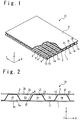
- FIG. 1 is a perspective view showing a composite material structure 10 according to the first embodiment of the present invention.
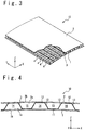
- FIG. 2 is a side view showing the composite material structure 10.
- the XYZ rectangular coordinates system is sometimes used. That is, in the following description, the X axial direction, the Y axial direction, and the Z axial direction are orthogonal to each other.
- the composite material structure 10 is composed of face plates 1 and 2 and a corrugated core 3.
- Each of the face plates 1 and 2 and the corrugated core 3 is composed of a composite material (that is, a material in which a fiber (e.g. a carbon fiber and a glass fiber) and a resin (e.g. epoxy and phenol) are combined).
- the face plates 1 and 2 are disposed to oppose to each other, and the corrugated core 3 is bonded to the face plates 1 and 2 between them. That is, the face plate 1 is bonded to one main surface of the corrugated core 3 and the face plate 2 is bonded to the other main surface of the corrugated core 3 which is opposite to the one main surface.
- the word of "bonding" in this embodiment includes a meaning of bonding members formed separately, by an adhesive material or other techniques, and a meaning of integrally shaping the members formed separately as a single structure.
- the corrugated core 3 has a bonding section 11 bonded to the face plate 1, a bonding section 12 bonded to the face plate 2, and a coupling section 13 connecting the bonding sections 11 and 12.
- the coupling section 13 is coupled to the bonding sections 11 and 12 to be oblique to inner surfaces 1a and 2a of the face plates 1 and 2.
- the coupling section 13 may be coupled to the bonding sections 11 and 12 to be orthogonal to the inner surfaces 1a and 2a of the face plates 1 and 2. All of the bonding sections 11 and 12 and the coupling section 13 are disposed to extend in the Y axial direction (a first direction along the face plates 1 and 2).
- the bonding sections 11 and 12 and the coupling section 13 are all arranged repetitively in the X axial direction (in a second direction along the face plates 1 and 2 and different from the first direction).
- a space 14 surrounded by the bonding section 12 of the corrugated core 3, the coupling sections 13, and the inner surface 1a of the face plate 1, and a space 15 surrounded by the bonding section 11 of the corrugated core 3, the coupling sections 13, and the inner surface 2a of the face plate 2 are formed inside the composite material structure 10.
- the corrugated core 3 has the structure in which the spaces 14 and 15 extend in the Y axial direction, and are alternately arranged in the X axial direction. Such a structure makes it possible to realize an extremely strong structure with the small number of parts and to utilize the advantage of the composite material structure effectively.
- the bonding sections 11 and 12 and the coupling section 13 are repeatedly arranged such that a periodic structure in the X axial direction is formed in the corrugated core 3.
- the shape of the corrugated core 3, i.e. the shape of the bonding sections 11 and 12 and the coupling section 13 is not always limited to the periodic structure in the X axial direction, and the structure of the corrugated core 3 may depend on the position of the composite material structure 10.
- a plurality of openings 4 are provided in the corrugated core 3.
- the plurality of openings 4 are arranged in the Y axial direction in each of the coupling sections 13.
- the stiffness of the composite material structure 10 can be properly controlled and adjusted. This is useful to improve shapability in the manufacturing process.
- the composite material structure 10 of the present embodiment in which the openings 4 are formed in the corrugated core 3, has various additional advantages.
- the composite material structure 10 of the present embodiment has the advantage that it is possible to freely set the strength and stiffness of the composite material structure 10, by adjusting the thicknesses of the composite materials of the face plates 1 and 2, and the corrugated core 3, and a stacking method of fiber layers (angle in stacking), and by designing the shape of opening 4 appropriately.
- the formation of the openings 4 in the corrugated core 3 realizes the reduction of the load of the composite material structure 10.
- access to various positions of the composite material structure 10 is possible through the openings 4. Thus, it is possible to improve the inspection easiness of various portions of the composite material structure 10.
- the composite material structure 10 of the present embodiment may be used as a liquid tank that stores liquid such as fuel in the space between the face plates 1 and 2, e.g. a fuel tank.
- the openings 4 are formed in the corrugated core 3 to have a truss structure.
- Such a structure is effective to transfer the shear load efficiently and to counter the shear load in the composite material structure 10.
- the shape of openings 4 can be changed variously according to the purpose. The ideal shape of openings 4 will be discussed later in detail.
- the structure 1 in which the composite material structure 10 having the flat face plates 1 and 2, that is, the structure in which the outer surfaces 1b and 2b of the face plates 1 and 2 are flat is shown in FIG. 1 and FIG. 2 .
- the outer surfaces 1b and 2b of the face plates 1 and 2 may be curved surfaces.
- the composite material structure 10 of the present embodiment is suitable especially in case that the outer surfaces 1b and 2b of the face plates 1 and 2 have complicated curved surfaces.
- FIG. 1 and FIG. 2 the structure in which the openings 4 are provided only to the coupling section 13 of the corrugated core 3 (that is, the structure in which the openings 4 are provided only to a portion of the corrugated core 3 away from the face plate 1) is shown in FIG. 1 and FIG. 2 .
- the openings 4 may be provided to optional positions of the corrugated core 3 (containing the bonding sections 11 and 12).
- FIG. 5 and FIG. 6 are diagrams showing the composite material structure of an exemplary embodiment which is not according to the invention as claimed.
- FIG. 5 is a perspective view showing the composite material structure 10A of the exemplary embodiment.
- FIG. 6 is a side view showing the composite material structure 10A.
- the composite material structure 10A has the structure in which the face plate 2 is removed from the composite material structure 10 of FIG. 1 and FIG. 2 .
- the bonding section 12 of the corrugated core 3 is not bonded to the face plate 2 and functions as a portion for coupling a neighboring coupling section 13.
- the space 14 surrounded by the bonding section 12 of the corrugated core 3, the coupling section 13 and the inner surface 1a of the face plate 1 is formed inside the composite material structure 10A.
- the space 14 extends in the Y axial direction.
- the openings 4 are provided to the corrugated core 3.
- the composite material structure 10A shown in FIG. 5 and FIG. 6 has strength lower than in the composite material structure 10 shown in FIG. 1 and FIG. 2 , but has the same effect in that a high-strength structure is realized with the small number of parts and the advantage of the composite material structure can be utilized effectively.
- openings 4 are provided only to the coupling section 13 , but the openings 4 may be provided on optional positions of the corrugated core 3 (containing the bonding sections 11 and 12).
- FIG. 5 and FIG. 6 show the structure when the outer surface 1b of the face plate 1 (the surface which is opposite to the corrugated core 3) is a flat surface, but the outer surface 1b of the face plate 1 may be a curved surface, as shown in FIG. 7 and FIG. 8 .
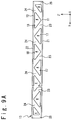
- FIG. 9A to FIG. 9D are side views showing the structure of the corrugated core 3 suitable to transfer a shear load efficiently in the composite material structure 10 or 10A (that is, the shape of the openings 4 provided for the corrugated core 3).
- FIG. 9A to FIG. 9D show the structure when the coupling section 13 of the corrugated core 3 is viewed in the direction of the arrow A of FIG. 2 .
- the shape of openings 4 is shown when viewing in a direction orthogonal to not the Z axial direction but the Y axial direction and in a Z' axial direction which is a direction along the coupling section 13.
- the upper and lower direction in FIG. 9A to FIG. 9D is the Z' axial direction.
- FIG. 9A shows an example of the coupling section 13 in which the truss structure has been formed.
- the openings 4 are arranged in the Y axial direction in the coupling section 13 of the corrugated core 3 in the structure of FIG. 9A .
- Each of the openings 4 other than the openings 4 in the both ends is formed as an almost isosceles triangular shape in which each corner is rounded.
- Each of the openings 4 in the both ends is formed by a right triangular shape in which each corner is rounded.
- the opening 4 having a side 17 opposite to the bonding section 11 and the opening 4 having a side 18 opposite to the bonding section 12 are alternately arranged on a line.
- base sections 21 and 22, diagonal column sections 23 and 24, and column sections 25 are formed in the coupling section 13.
- the base section 21 is connected to the bonding section 11 and is disposed to extend in the Y axial direction along the bonding section 11.
- the base section 22 is connected to the bonding section 12 and is disposed to extend in the Y axial direction along the bonding section 12.
- the bonding section 11 is a portion that bonded to the face plate 1
- the bonding section 12 is a portion that is bonded to the face plate 2 (when the face plate 2 is disposed).
- the diagonal column sections 23 and 24 are connected to the base sections 21 and 22 by extending diagonally to the base sections 21 and 22 (i.e. diagonally to the Y axial direction).
- the diagonal column section 23 is connected to the base sections 21 and 22 such that the position in the Y axial direction of the end of the section 23 connected to the base section 22 is shifted in the +Y axial direction from the position of the end of the section 23 connected to the base section 21.
- the diagonal column section 24 is connected to the base sections 21 and 22 such that the position in the Y axial direction of the end of the section 24 connected to the base section 21 is shifted in the +Y axial direction from the position of the end of the section 24 connected to the base section 22.
- the column sections 25 extend perpendicularly from the base sections 21 and 22 to the base sections 22 and 21 to connect the base sections 21 and 22.
- the diagonal column sections 23 and 24 are disposed to extend diagonally to the base sections 21 and 22 to connect the base sections 21 and 22.
- the shear load can be transferred efficiently in the composite material structure 10 or 10A.
- the structure of such a coupling section 13 is effective to receive the shear load which acts on the composite material structure 10 or 10A while reducing the weight of the composite material structure 10 or 10A.
- FIG. 9B is a side view showing another example of the structure of the coupling section 13 of the corrugated core 3 to transfer the shear load efficiently inside the composite material structure 10 or 10A.
- the openings 4 are arranged on the coupling section 13 in the Y axial direction in the structure of FIG. 9B , too.
- each of of the openings 4 other than the openings on the both ends of the coupling section 13 is formed as a right angle trapezoidal shape in which the corner is rounded.
- Each of the openings on the both ends of the coupling section 13 is formed as a right triangular shape in which the corner is rounded.
- openings 4 other than the openings on the both ends of the coupling section 13 there are one type of opening 4 in which the length of a side 17 opposite to the bonding section 11 in the Y axial direction is longer than the length of a side 18 opposite to the bonding section 12 in the Y axial direction, and another type of opening 4 in which the length of the side 17 opposite to the bonding section 11 in the Y axial direction is shorter than the length of the side 18 opposite to the bonding section 12 in the Y axial direction.
- These openings 4 are alternately arranged.
- the base sections 21 and 22, the diagonal column sections 23 and 24 and the column sections 25 and 26 are formed in the coupling section 13.
- the base section 21 is connected to the bonding section 11 and is disposed to extend in the Y axial direction along the bonding section 11.
- the base section 22 is connected to the bonding section 12 and is disposed to extend in the Y axial direction along the bonding section 12.
- the diagonal column sections 23 and 24 extend diagonally to the base sections 21 and 22 (i.e. diagonally to the Y axial direction) to connect the base sections 21 and 22.
- the diagonal column section 23 is connected to the base sections 21 and 22 such that the position in the Y axial direction of the end of the section 23 connected to the base section 21 is shifted in the +Y axial direction from the position in the Y axial direction of the end of the section 23 connected to the base section 22, and the diagonal column section 24 is connected to the base sections 21 and 22 such that the position in the Y axial direction of the end of the section 24 connected to the base section 21 is shifted in the +Y axial direction from the position in the Y axial direction of the end of the section 24 connected to the base section 22.
- the column section 25 is disposed to extend perpendicularly from the ends of the base sections 21 and 22 to the base section 22 and 21 to connect the base sections 21 and 22. Also, the column section 26 is disposed between the neighbor diagonal column sections 23 and 24, to extend perpendicularly from the ends of the base sections 21 and 22 to the base section 22 and 21 to connect the base sections 21 and 22.
- the shear load can be efficiently transferred inside the composite material structure 10 or 10A.
- the structure of such a coupling section 13 is effective to support the shear load which acts on the composite material structure 10 or 10A while reducing the weight of the composite material structure 10 or 10A.
- the column sections 26 extend perpendicularly to the base sections 21 and 22 to connect the base sections 21 and 22, Improving about the strength to the load in the board thickness direction (the load which acts in the direction of the board thickness (in the Z axial direction)).
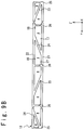
- FIG. 9C is a side view showing a still another example of the structure of the coupling section 13 of the corrugated core 3 to transfer a shear load efficiently inside the composite material structure 10 or 10A.
- the openings 4 are arranged in the Y axial direction in the coupling section 13.
- the truss structure is formed in the coupling section 13.
- each opening 4 is formed to have a right triangular shape in which each of corners is rounded.
- the base sections 21 and 22, the diagonal column sections 23 and 24 and the column sections 25, 26 are formed in the coupling section 13.
- the base section 21 is connected to the bonding section 11 and is disposed to extend in the Y axial direction along the bonding section 11.
- the base section 22 is connected to the bonding section 12 and is disposed to extend in the Y axial direction along the bonding section 12.
- the diagonal column sections 23 and 24 extend diagonally to the base sections 21 and 22 (i.e. diagonally in the Y axial direction) to connect the base sections 21 and 22.
- the diagonal column section 23 is connected to the base sections 21 and 22 such that the position in the Y axial direction of the end of the section 23 connected to the base section 22 is shifted in the +Y direction from the position of the end of the section 23 connected to the base section 21.
- the diagonal column section 24 is connected to the base sections 21 and 22 so that the position in the Y axial direction of the end of the section 24 connected to the base section 21 is shifted in the +Y direction from the position of the end of the section 24 connected to the base section 22.
- the diagonal column sections 23 and 24 are disposed to contact each other in the structure of FIG.
- each column section 26 is disposed to be connected to a contact portion of the diagonal column section 23 and 24 at its one end and to be connected to the base section 21 or 22 at its other end.
- the column section 26 extends perpendicularly to the base sections 21 and 22 to connect the base sections 21 and 22.
- the shear load can be efficiently transferred inside the composite material structure 10 or 10A.
- the structure of such a coupling section 13 is effective to support the shear load which acts on the composite material structure 10 or 10A while reducing the weight of the composite material structure 10 or 10A.
- the column section 26 is disposed to extend perpendicularly to the base sections 21 and 22 to connect the base sections 21 and 22, the strength to the load in a board thickness direction (the load which acts in the board thickness direction (the Z axial direction)).
- FIG. 9D is a side view showing a further another example of the structure of the coupling section 13 of the corrugated core 3 to efficiently transfer a shear load inside the composite material structure 10 or 10A.
- the openings 4 are arranged in the Y axial direction in the coupling section 13 in the structure of FIG. 9D .
- the openings 4a to 4d of four kinds are provided in the coupling section 13, and thus, the truss structure is formed in the coupling section 13.
- the opening 4a has a diamond shape in which each corner is rounded.
- the opening 4b has an isosceles triangular shape in which each corner is rounded and has a side 17 opposite to the bonding section 11.
- the opening 4c has an isosceles triangular shape in which each corner is rounded and has a side 18 opposite to the bonding section 12.
- a pair of openings 4b and 4c is arranged in a direction orthogonal to the Y axial direction.
- the opening 4d has an isosceles triangular shape in which each corner is rounded and is arranged on either end of the row of openings 4.
- the base sections 21 and 22, the diagonal column sections 23 and 24 and the column sections 25 are formed in the coupling section 13.
- the base section 21 is connected to the bonding section 11 and is disposed to extend in the Y axial direction along the bonding section 11.
- the base section 22 is connected to the bonding section 12 and is disposed to extend in the Y axial direction along the bonding section 12.
- the diagonal column sections 23 and 24 extend diagonally to the base sections 21 and 22 (i.e. diagonally in the Y axial direction) to connect the base sections 21 and 22.
- the diagonal column section 23 is connected to the base sections 21 and 22 so that the position in the Y axial direction of the end of the section 23 connecting to the base section 22 is shifted in the +Y direction from the end of the section 23 connected to the base section 21.
- the diagonal column section 24 is connected to the base sections 21 and 22 so that the position in the Y axial direction of the end of the section 24 connected to the base section 21 is shifted in the +Y direction from the position of the end of the section 24 connecting to the base section 22.
- the diagonal column sections 23 and 24 are provided to intersect each other and the diagonal column sections 23 and 24 are coupled at the center.
- the column sections 25 extend perpendicularly to the base sections 21 and 22 from the ends of the base sections 21 and 22 to connect the base sections 21 and 22.
- the shear load can be efficiently transferred inside the composite material structure 10 or 10A.
- the structure of such a coupling section 13 is effective to support the shear load which acts on the composite material structure 10 or 10A while reducing the weight of the composite material structure 10 or 10A.
- FIG. 10A to FIG. 10C are side views showing the structure of the corrugated core 3 (that is, a shape of the openings 4 provided to the corrugated core 3) suitable for efficiently transferring a board thickness direction load (i.e. the load which acts in the board thickness direction (the Z axial direction)) inside the composite material structure 10 or 10A.
- a board thickness direction load i.e. the load which acts in the board thickness direction (the Z axial direction)
- FIG. 10A to FIG. 10C show the structure when the coupling section 13 of the corrugated core 3 is viewed to the direction of the arrow A in FIG. 2 .
- the Z' axial direction a direction perpendicular to the Y axial direction along coupling section 13
- the upper and lower direction in the FIG. 10A to FIG. 10C is the Z' axial direction.
- FIG. 10A is a side view showing an example of the structure of the coupling section 13 of the corrugated core 3 to efficiently transfer a shear load inside the composite material structure 10 or 10A.
- Rectangular openings 4 are arranged in the Y axial direction in the coupling section 13 in the structure of the FIG. 10A .
- the base sections 21 and 22 and the column sections 25 and 26 are formed in the coupling section 13 because of the openings 4 of such a shape.
- the base section 21 is connected to the bonding section 11 and is disposed to extend in the Y axial direction along the bonding section 11.
- the base section 22 is connected to the bonding section 12 and is disposed to extend in the Y axial direction along the bonding section 12.
- the column sections 25 and 26 extend perpendicularly to the base sections 21 and 22 to connect the base sections 21 and 22.
- the column section 25 is connecting to the ends of the base sections 21 and 22 and the column section 26 is connected to the base sections 21 and 22 at a middle position of the base sections 21 and 22.
- the load in the board thickness direction can be efficiently transferred inside the composite material structure 10 or 10A.
- the structure of such a coupling section 13 is effective to support the load in the board thickness direction which acts on the composite material structure 10 or 10A while reducing the weight of the composite material structure 10 or 10A.
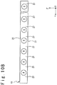
- FIG. 10B is a side view showing another example of the structure of the coupling section 13 of the corrugated core 3 to efficiently transfer a shear load inside the composite material structure 10 or 10A.
- the circular openings 4 are arranged in the Y axial direction in the coupling section 13.
- the base sections 21 and 22 and the column sections 27 are formed in the coupling section 13.
- the base section 21 is connected to the bonding section 11 and is disposed to extend in the Y axial direction along the bonding section 11.
- the base section 22 is connected to the bonding section 12 and is disposed to extend in the Y axial direction along the bonding section 12.
- the column section 27 extends perpendicularly to the base sections 21 and 22 to connect the base sections 21 and 22.
- the load in the board thickness direction can be efficiently transferred inside the composite material structure 10 or 10A.
- the structure of such a coupling section 13 is effective to support the load in the board thickness direction that acts on the composite material structure 10 or 10A while reducing the weight of the composite material structure 10 or 10A.
- FIG. 10C is a side view showing still another example of the structure of the coupling section 13 of the corrugated core 3 to efficiently transfer a shear load inside the composite material structure 10 or 10A.
- the openings 4 having an oval shape long in a direction orthogonal to the Y axial direction are arranged in the Y axial direction of the coupling section 13.
- the term of "oval” in this Specification is used in the meaning that contains both of an ellipse and a shape in which two semicircles are combined by two parallel lines.
- the base section 21 is connected to the bonding section 11 and is disposed to extend in the Y axial direction along the bonding section 11. Also, the base section 22 is connected to the bonding section 12 and is disposed to extend in the Y axial direction along the bonding section 12.
- the column section 27 extends perpendicular to the base sections 21 and 22 to connect the base sections 21 and 22.
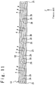
- FIG. 11 is a side view showing the structure of the corrugated core 3 suitable for efficiently transferring the load which acts on an axial direction (i.e. the Y axial direction) inside the composite material structure 10 or 10A (that is, a shape of the opening 4 formed in the corrugated core 3).
- FIG. 11 shows the structure when the coupling section 13 of the corrugated core 3 is viewed in the direction of the arrow A in FIG. 2 .
- the Z axial direction but the Z' axial direction (a direction perpendicular to the Y axial direction and along the coupling section 13) is shown.
- the upper and lower direction in FIG. 11 is the Z' axial direction.
- substantially rectangular openings 4 are arranged in the coupling section 13 in a matrix manner (i.e., arranged in the Y axial direction and the Z' axial direction).
- the base sections 21 and 22, the column sections 25 and 26 and beam sections 28 are formed in the coupling section 13.
- the base section 21 is connected to the bonding section 11 and is disposed to extend in the Y axial direction along the bonding section 11.
- the base section 22 is connected to the bonding section 12 and is disposed to extend in the Y axial direction along the bonding section 12.
- the column sections 25 and 26 extend perpendicularly to the base sections 21 and 22 to connect the base sections 21 and 22.
- the column section 25 is connecting to the ends of the base sections 21 and 22, and the column section 26 is connected to the base sections 21 and 22 in the middle position of the base sections 21 and 22.
- the beam section 28 extends in the axial direction of the composite material structure 10 or 10A (i.e. in the Y axial direction) to connect the neighbor column sections 25 and 26.
- the structure of FIG. 11 can efficiently transfer the axial direction load inside the composite material structure 10 or 10A.
- the structure of such a coupling section 13 is effective to support the axial direction load which acts on the composite material structure 10 or 10A while reducing the weight of the composite material structure 10 or 10A.
- the face plates 1 and 2 and the corrugated core 3 can be manufactured by various methods.
- the face plate 1 and the corrugated core 3 may be manufactured as an integrated member.
- the face plate 1 and the corrugated core 3 are manufactured as separate members, and then they are may be bonded.
- the face plate 2 and the corrugated core 3 may be manufactured as separate members and then they may be bonded.
- all of the face plates 1 and 2 and the corrugated cores 3 may be manufactured as an integrated member.
- intermediate products from which the face plates 1 and 2 and the corrugated core 3 are finally formed, are formed a sheet-like or tape-like prepreg, respectively.
- the intermediate products may be bonded by co-curing, co-bonding or a secondary adhesion.
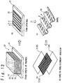
- FIG. 12 is a conceptual diagram showing an example of the manufacturing method for manufacturing the composite material structure 10 by using the sheet-like prepreg.
- the sheet-like prepreg 32 is stacked on a flat mandrel 31 to form a stacked layers structure 33 ( FIG. 12(a) ).
- the stacked layers structure 33 is the intermediate product from which the corrugated core 3 is formed in the following process.
- the number of sheets of the prepreg 32 to be stacked and the direction of fiber in each sheet of the prepreg 32 are determined such that the corrugated core 3 to be formed finally, has appropriate strength and stiffness.
- the openings 4 are formed in the stacked layer structure 33 by punching or cutting ( FIG. 12(b) ).
- the stacked layer structure 33 is shaped to have the shape of the corrugated core 3 to be formed finally, by pressing or draping ( FIG. 12(c) ). At this time, the stacked layer structure 33 is in the un-cured condition.
- the face plates 1 and 2 and the corrugated core 3 which are shaped as separate members, are bonded to each other and then the manufacture of the composite material structure 10 completes ( FIG. 12(d) ).
- the bonding of the face plates 1 and 2 and the corrugated core 3 can be carried out by various techniques.
- the face plates 1 and 2 and the corrugated core 3 may be bonded by co-curing.
- un-cured members 34 and 35 from which the face plates 1 and 2 can be formed finally, are formed by stacking the sheets of prepreg.
- the members 34 and 35 in addition to the stacked layer structure 33 are cured so that the composite material structure 10 is completed in which the face plates 1 and 2 and the corrugated core 3 are bonded to each other.
- the face plates 1 and 2 and the corrugated core 3 may be bonded by co-bonding.
- the stacked layer structure 33 is cured to form the corrugated core 3
- the un-cured members 34 and 35, from which the face plates 1 and 2 are formed finally, are formed by stacking the sheets of prepreg.
- the curing is carried out in the state that the un-cured members 34 and 35 are brought into contact with the corrugated core 3 through the adhesive materials.
- the composite material structure 10 is completed in which the face plates 1 and 2 and the corrugated core 3 are bonded to each other.
- the face plates 1 and 2 and the corrugated core 3 may be bonded through a secondary adhesion.
- a stacked layer structure 33 is cured to form the corrugated core 3, whereas the face plates 1 and 2 after the curing are formed.
- the cured corrugated core 3 is brought into contact with the cured face plates 1 and 2 and the adhesive material is cured in such a condition.
- the composite material structure 10 in which the face plates 1 and 2 and the corrugated core 3 are bonded is completed.
- FIG. 13 is a conceptual diagram showing an example of the manufacturing method which manufactures the composite material structure 10 by using a tape-like prepreg (a prepreg tape).
- the prepreg tape 36 is stacked on a flat mandrel 31 and the stacked layer structure 33 is formed in which the openings 4 have been formed ( FIG. 13(a) ).
- the prepreg tape 36 may be stacked by using an AFP (automated fiber placement) technique.
- the stacked layer structure 33 of a desired shape can be formed by using the prepreg tape. Therefore, note that it is not necessary to form the openings 4 by a punching technique and a cutting technique.
- the stacked layer structure 33 is shaped to have the final shape of the corrugated core 3, by a pressing technique and a draping technique, like the manufacturing method of FIG. 12 ( FIG. 13(b) ). Moreover, a process which bonds the face plates 1 and 2 and the corrugated core 3 is carried out ( FIG. 13(c) ). Like the manufacturing method of FIG. 12 , either of co-curing, co-bond, and the second adhesive material may be used in the process which bonds the face plates 1 and 2 and the corrugated core 3. Through the above process, the composite material structure 10 is completed.
- FIG. 14 is a conceptual diagram showing a manufacturing method which manufactures the composite material structure 10 by using an RTM (resin transfer molding) technique to impregnate a resin into a dry preform.
- RTM resin transfer molding
- the dry preform 41 which has openings 4 is prepared ( FIG. 14(a) ).
- the dry preform 41 having the opening 4 may be shaped to form the opening 4 by carrying out the punching technique and the cutting technique of a flat-plate-like dry preform.
- the resin is impregnated into the dry preform 41 by the RTM, to form the corrugated core 3 ( FIG. 14(b) ).
- the resin is impregnated in the condition that the dry preform 41 is put between the mandrels 42 and 43, and moreover, the resin is cured at the desired temperature.
- the cured corrugated core 3 is completed.
- the face plates 1 and 2 and the corrugated core 3 may be bonded by co-bonding.
- the un-cured members 34 and 35, from which the face plates 1 and 2 are formed finally, are formed by stacking the sheets of prepreg.
- the curing is carried out in the state that the cured corrugated core 3 is made contact the un-cured members 34 and 35 through the adhesive materials.
- the composite material structure 10 completes in which the face plates 1 and 2 and the corrugated core 3 are bonded to each other.
- the face plates 1 and 2 and the corrugated core 3 may be bonded by the secondary adhesion.
- the cured face plates 1 and 2 are prepared, and then the curing is carried out in the state that the cured corrugated core 3 is made contact the cured face plates 1 and 2 through the adhesive materials.
- the composite material structure 10 completes in which the face plates 1 and 2 and the corrugated core 3 are bonded to each other.
- the manufacture of the composite material structure 10A that does not have the face plate 2 can be realized by not bonding the face plate 2 to the corrugated core 3, in the above-mentioned manufacturing method.
Landscapes
- Engineering & Computer Science (AREA)
- Mechanical Engineering (AREA)
- Laminated Bodies (AREA)
Applications Claiming Priority (2)
| Application Number | Priority Date | Filing Date | Title |
|---|---|---|---|
| JP2014019566A JP6238168B2 (ja) | 2014-02-04 | 2014-02-04 | 複合材構造 |
| PCT/JP2015/052407 WO2015119023A1 (ja) | 2014-02-04 | 2015-01-28 | 複合材構造 |
Publications (3)
| Publication Number | Publication Date |
|---|---|
| EP3081373A1 EP3081373A1 (en) | 2016-10-19 |
| EP3081373A4 EP3081373A4 (en) | 2016-12-07 |
| EP3081373B1 true EP3081373B1 (en) | 2019-04-03 |
Family
ID=53777830
Family Applications (1)
| Application Number | Title | Priority Date | Filing Date |
|---|---|---|---|
| EP15745972.8A Active EP3081373B1 (en) | 2014-02-04 | 2015-01-28 | Composite material structure |
Country Status (7)
Families Citing this family (5)
| Publication number | Priority date | Publication date | Assignee | Title |
|---|---|---|---|---|
| EP3498591A1 (en) * | 2017-12-13 | 2019-06-19 | AIRBUS HELICOPTERS DEUTSCHLAND GmbH | A composite truss beam with a sandwich web |
| CN108407400A (zh) * | 2018-01-25 | 2018-08-17 | 大连理工大学 | 碳纤维增强复合材料波纹芯夹层结构汽车防撞梁 |
| DE102018207763A1 (de) * | 2018-05-17 | 2019-11-21 | Airbus Operations Gmbh | Rumpfstruktur für ein Luftfahrzeug |
| CN109501404B (zh) * | 2018-11-20 | 2021-02-02 | 华侨大学 | 一种高效减振的层级多孔复合板 |
| FR3091263A1 (fr) * | 2018-12-28 | 2020-07-03 | Daher Aerospace | Bec de bord d’attaque à structure optimisée |
Family Cites Families (22)
| Publication number | Priority date | Publication date | Assignee | Title |
|---|---|---|---|---|
| JPS5668096A (en) * | 1979-11-06 | 1981-06-08 | Victor Co Of Japan Ltd | Speaker diaphragm |
| JPS58159320U (ja) * | 1982-04-19 | 1983-10-24 | 株式会社ニチベイ | 間仕切用パネル |
| JPS58191790U (ja) * | 1982-06-15 | 1983-12-20 | 赤井電機株式会社 | スピ−カ用振動板 |
| JPH047136A (ja) * | 1990-04-25 | 1992-01-10 | Hitachi Ltd | 地上用複合構造材 |
| JPH04237700A (ja) * | 1991-01-17 | 1992-08-26 | Hitachi Ltd | 宇宙往還機用熱防護材 |
| JPH06191491A (ja) * | 1992-07-06 | 1994-07-12 | Rockwell Internatl Corp | 層流制御に使われるタイプの穴を開けられたパネルの表面に圧力の離散領域を確立するシステム |
| ATE189160T1 (de) * | 1992-08-03 | 2000-02-15 | Supracor Inc | Perforierter wabenkörper |
| JPH0716968A (ja) * | 1993-06-29 | 1995-01-20 | Akiya Ozeki | 高強度軽量立体構造の製造方法。 |
| US5469686A (en) * | 1993-09-27 | 1995-11-28 | Rockwell International Corp. | Composite structural truss element |
| JPH07172395A (ja) * | 1993-12-20 | 1995-07-11 | Mitsubishi Heavy Ind Ltd | 航空機のインテグラルタンク |
| US6187411B1 (en) * | 1996-10-04 | 2001-02-13 | The Boeing Company | Stitch-reinforced sandwich panel and method of making same |
| JPH11286062A (ja) * | 1998-04-02 | 1999-10-19 | Nippon Light Metal Co Ltd | サンドイッチパネル |
| US6220286B1 (en) * | 1999-01-29 | 2001-04-24 | Michael L. Davenport | Gas blanket distributor |
| JP3753313B2 (ja) * | 1999-11-26 | 2006-03-08 | 三洋化成工業株式会社 | サンドイッチ構造体用ハニカム芯材及びその製造方法 |
| JP2001231815A (ja) * | 2000-02-24 | 2001-08-28 | Nippon Kyushutai Gijutsu Kenkyusho:Kk | 吸収体製品の表面被覆シート |
| US6893733B2 (en) * | 2000-07-07 | 2005-05-17 | Delphi Technologies, Inc. | Modified contoured crushable structural members and methods for making the same |
| US6910659B2 (en) * | 2002-10-22 | 2005-06-28 | The Boeing Company | Method and apparatus for liquid containment, such as for aircraft fuel vessels |
| US7625618B1 (en) * | 2003-05-15 | 2009-12-01 | Rohr, Inc. | Advanced composite aerostructure article having a braided co-cured fly away hollow mandrel and method for fabrication |
| US8815038B2 (en) * | 2008-10-01 | 2014-08-26 | The Boeing Company | Joining curved composite sandwich panels |
| DE102009013514A1 (de) * | 2009-03-19 | 2010-09-30 | Kautex Textron Gmbh & Co. Kg | Kunststoff-Kraftstoffbehälter |
| US9346533B2 (en) * | 2011-10-19 | 2016-05-24 | The Boeing Company | Attachment of aircraft ribs to spars having variable geometry |
| CN104203752A (zh) * | 2012-03-26 | 2014-12-10 | 三菱重工业株式会社 | 燃料箱、主翼、航空器主体、航空器及移动体 |
-
2014
- 2014-02-04 JP JP2014019566A patent/JP6238168B2/ja active Active
-
2015
- 2015-01-28 CN CN201580004813.0A patent/CN105916673B/zh not_active Expired - Fee Related
- 2015-01-28 WO PCT/JP2015/052407 patent/WO2015119023A1/ja active Application Filing
- 2015-01-28 US US15/112,903 patent/US20160339668A1/en not_active Abandoned
- 2015-01-28 CA CA2938645A patent/CA2938645C/en active Active
- 2015-01-28 EP EP15745972.8A patent/EP3081373B1/en active Active
- 2015-01-28 RU RU2016127706A patent/RU2641733C1/ru active
Non-Patent Citations (1)
| Title |
|---|
| None * |
Also Published As
| Publication number | Publication date |
|---|---|
| JP2015145124A (ja) | 2015-08-13 |
| EP3081373A1 (en) | 2016-10-19 |
| CN105916673B (zh) | 2017-09-22 |
| RU2641733C1 (ru) | 2018-01-22 |
| US20160339668A1 (en) | 2016-11-24 |
| CA2938645A1 (en) | 2015-08-13 |
| CN105916673A (zh) | 2016-08-31 |
| CA2938645C (en) | 2017-10-10 |
| EP3081373A4 (en) | 2016-12-07 |
| JP6238168B2 (ja) | 2017-11-29 |
| WO2015119023A1 (ja) | 2015-08-13 |
Similar Documents
| Publication | Publication Date | Title |
|---|---|---|
| EP3081373B1 (en) | Composite material structure | |
| US6743504B1 (en) | Co-cured composite structures and method of making them | |
| US8642168B2 (en) | Composite structure having reinforced core and method of making the same | |
| US4789577A (en) | Multichannel structures made of composites, processes and semifinished products for the manufacture thereof | |
| EP2790898B1 (en) | Composite strut and fabrication method | |
| CN104669728B (zh) | 具有加强芯部的复合结构及其制造方法 | |
| US9120246B2 (en) | Pressure tunable expandable mandrel for manufacturing a composite structure | |
| US20020189195A1 (en) | Composite structural panel with undulated body | |
| KR101353112B1 (ko) | 복합재 부재의 제조 방법 및 프리프레그 시트의 적층체 | |
| US20130333830A1 (en) | Flexible Compactor with Reinforcing Spine | |
| EP2865516A1 (en) | Skin-stiffened composite panel and method of its manufacture | |
| CN110104202B (zh) | 使用铰接式芯轴的复合飞机制造工具 | |
| JP5731392B2 (ja) | 航空機の平面部材およびその製造方法 | |
| JP6112178B2 (ja) | サンドイッチパネルおよびサンドイッチパネルの製造方法 | |
| JP5861448B2 (ja) | サンドイッチパネルの製造方法 | |
| JP7548722B2 (ja) | 複合ストリンガ及び複合ストリンガを形成するための方法 | |
| US20060280927A1 (en) | Lightweight composite fairing bar an method for manufacturing the same | |
| EP3034283A1 (en) | Method of forming a laminar composite structure | |
| US7939158B2 (en) | Double walled structural reinforcement | |
| EP4060140B1 (en) | Core member and method for its manufacture | |
| CN208438808U (zh) | 复合材料及其芯材 | |
| EP2888095B1 (en) | A reinforced structure and a method for manufacturing a reinforced structure | |
| US7083753B2 (en) | Honeycomb core composite article and method and apparatus for making same | |
| EP3650209B1 (en) | Method of manufacturing a first cured part and a second cured part | |
| KR102466802B1 (ko) | 복합소재 성형방법 및 이를 이용한 복합소재 성형품 |
Legal Events
| Date | Code | Title | Description |
|---|---|---|---|
| PUAI | Public reference made under article 153(3) epc to a published international application that has entered the european phase |
Free format text: ORIGINAL CODE: 0009012 |
|
| 17P | Request for examination filed |
Effective date: 20160715 |
|
| AK | Designated contracting states |
Kind code of ref document: A1 Designated state(s): AL AT BE BG CH CY CZ DE DK EE ES FI FR GB GR HR HU IE IS IT LI LT LU LV MC MK MT NL NO PL PT RO RS SE SI SK SM TR |
|
| AX | Request for extension of the european patent |
Extension state: BA ME |
|
| A4 | Supplementary search report drawn up and despatched |
Effective date: 20161109 |
|
| RIC1 | Information provided on ipc code assigned before grant |
Ipc: B32B 27/08 20060101ALI20161103BHEP Ipc: B32B 27/42 20060101ALI20161103BHEP Ipc: B64C 3/34 20060101ALI20161103BHEP Ipc: B32B 3/26 20060101ALI20161103BHEP Ipc: B32B 3/28 20060101AFI20161103BHEP Ipc: B32B 27/38 20060101ALI20161103BHEP |
|
| DAX | Request for extension of the european patent (deleted) | ||
| GRAP | Despatch of communication of intention to grant a patent |
Free format text: ORIGINAL CODE: EPIDOSNIGR1 |
|
| STAA | Information on the status of an ep patent application or granted ep patent |
Free format text: STATUS: GRANT OF PATENT IS INTENDED |
|
| INTG | Intention to grant announced |
Effective date: 20181009 |
|
| GRAS | Grant fee paid |
Free format text: ORIGINAL CODE: EPIDOSNIGR3 |
|
| GRAA | (expected) grant |
Free format text: ORIGINAL CODE: 0009210 |
|
| STAA | Information on the status of an ep patent application or granted ep patent |
Free format text: STATUS: THE PATENT HAS BEEN GRANTED |
|
| RIN1 | Information on inventor provided before grant (corrected) |
Inventor name: TAKAGI, KIYOKA Inventor name: ISHIDA, TAKASHI Inventor name: YOSHINO, KATSUYA Inventor name: ABE, TOSHIO Inventor name: KISHIMOTO, KAZUAKI Inventor name: KOYAMA, TAKAYUKI Inventor name: SAITO, KOICHI |
|
| AK | Designated contracting states |
Kind code of ref document: B1 Designated state(s): AL AT BE BG CH CY CZ DE DK EE ES FI FR GB GR HR HU IE IS IT LI LT LU LV MC MK MT NL NO PL PT RO RS SE SI SK SM TR |
|
| REG | Reference to a national code |
Ref country code: GB Ref legal event code: FG4D |
|
| REG | Reference to a national code |
Ref country code: CH Ref legal event code: EP Ref country code: AT Ref legal event code: REF Ref document number: 1115197 Country of ref document: AT Kind code of ref document: T Effective date: 20190415 |
|
| REG | Reference to a national code |
Ref country code: DE Ref legal event code: R096 Ref document number: 602015027599 Country of ref document: DE |
|
| REG | Reference to a national code |
Ref country code: IE Ref legal event code: FG4D |
|
| REG | Reference to a national code |
Ref country code: NL Ref legal event code: MP Effective date: 20190403 |
|
| REG | Reference to a national code |
Ref country code: LT Ref legal event code: MG4D |
|
| REG | Reference to a national code |
Ref country code: AT Ref legal event code: MK05 Ref document number: 1115197 Country of ref document: AT Kind code of ref document: T Effective date: 20190403 |
|
| PG25 | Lapsed in a contracting state [announced via postgrant information from national office to epo] |
Ref country code: NL Free format text: LAPSE BECAUSE OF FAILURE TO SUBMIT A TRANSLATION OF THE DESCRIPTION OR TO PAY THE FEE WITHIN THE PRESCRIBED TIME-LIMIT Effective date: 20190403 |
|
| PG25 | Lapsed in a contracting state [announced via postgrant information from national office to epo] |
Ref country code: HR Free format text: LAPSE BECAUSE OF FAILURE TO SUBMIT A TRANSLATION OF THE DESCRIPTION OR TO PAY THE FEE WITHIN THE PRESCRIBED TIME-LIMIT Effective date: 20190403 Ref country code: ES Free format text: LAPSE BECAUSE OF FAILURE TO SUBMIT A TRANSLATION OF THE DESCRIPTION OR TO PAY THE FEE WITHIN THE PRESCRIBED TIME-LIMIT Effective date: 20190403 Ref country code: LT Free format text: LAPSE BECAUSE OF FAILURE TO SUBMIT A TRANSLATION OF THE DESCRIPTION OR TO PAY THE FEE WITHIN THE PRESCRIBED TIME-LIMIT Effective date: 20190403 Ref country code: CZ Free format text: LAPSE BECAUSE OF FAILURE TO SUBMIT A TRANSLATION OF THE DESCRIPTION OR TO PAY THE FEE WITHIN THE PRESCRIBED TIME-LIMIT Effective date: 20190403 Ref country code: PT Free format text: LAPSE BECAUSE OF FAILURE TO SUBMIT A TRANSLATION OF THE DESCRIPTION OR TO PAY THE FEE WITHIN THE PRESCRIBED TIME-LIMIT Effective date: 20190803 Ref country code: AL Free format text: LAPSE BECAUSE OF FAILURE TO SUBMIT A TRANSLATION OF THE DESCRIPTION OR TO PAY THE FEE WITHIN THE PRESCRIBED TIME-LIMIT Effective date: 20190403 Ref country code: FI Free format text: LAPSE BECAUSE OF FAILURE TO SUBMIT A TRANSLATION OF THE DESCRIPTION OR TO PAY THE FEE WITHIN THE PRESCRIBED TIME-LIMIT Effective date: 20190403 Ref country code: NO Free format text: LAPSE BECAUSE OF FAILURE TO SUBMIT A TRANSLATION OF THE DESCRIPTION OR TO PAY THE FEE WITHIN THE PRESCRIBED TIME-LIMIT Effective date: 20190703 Ref country code: SE Free format text: LAPSE BECAUSE OF FAILURE TO SUBMIT A TRANSLATION OF THE DESCRIPTION OR TO PAY THE FEE WITHIN THE PRESCRIBED TIME-LIMIT Effective date: 20190403 |
|
| PG25 | Lapsed in a contracting state [announced via postgrant information from national office to epo] |
Ref country code: BG Free format text: LAPSE BECAUSE OF FAILURE TO SUBMIT A TRANSLATION OF THE DESCRIPTION OR TO PAY THE FEE WITHIN THE PRESCRIBED TIME-LIMIT Effective date: 20190703 Ref country code: PL Free format text: LAPSE BECAUSE OF FAILURE TO SUBMIT A TRANSLATION OF THE DESCRIPTION OR TO PAY THE FEE WITHIN THE PRESCRIBED TIME-LIMIT Effective date: 20190403 Ref country code: GR Free format text: LAPSE BECAUSE OF FAILURE TO SUBMIT A TRANSLATION OF THE DESCRIPTION OR TO PAY THE FEE WITHIN THE PRESCRIBED TIME-LIMIT Effective date: 20190704 Ref country code: LV Free format text: LAPSE BECAUSE OF FAILURE TO SUBMIT A TRANSLATION OF THE DESCRIPTION OR TO PAY THE FEE WITHIN THE PRESCRIBED TIME-LIMIT Effective date: 20190403 Ref country code: RS Free format text: LAPSE BECAUSE OF FAILURE TO SUBMIT A TRANSLATION OF THE DESCRIPTION OR TO PAY THE FEE WITHIN THE PRESCRIBED TIME-LIMIT Effective date: 20190403 |
|
| PG25 | Lapsed in a contracting state [announced via postgrant information from national office to epo] |
Ref country code: AT Free format text: LAPSE BECAUSE OF FAILURE TO SUBMIT A TRANSLATION OF THE DESCRIPTION OR TO PAY THE FEE WITHIN THE PRESCRIBED TIME-LIMIT Effective date: 20190403 Ref country code: IS Free format text: LAPSE BECAUSE OF FAILURE TO SUBMIT A TRANSLATION OF THE DESCRIPTION OR TO PAY THE FEE WITHIN THE PRESCRIBED TIME-LIMIT Effective date: 20190803 |
|
| REG | Reference to a national code |
Ref country code: DE Ref legal event code: R097 Ref document number: 602015027599 Country of ref document: DE |
|
| PG25 | Lapsed in a contracting state [announced via postgrant information from national office to epo] |
Ref country code: EE Free format text: LAPSE BECAUSE OF FAILURE TO SUBMIT A TRANSLATION OF THE DESCRIPTION OR TO PAY THE FEE WITHIN THE PRESCRIBED TIME-LIMIT Effective date: 20190403 Ref country code: SK Free format text: LAPSE BECAUSE OF FAILURE TO SUBMIT A TRANSLATION OF THE DESCRIPTION OR TO PAY THE FEE WITHIN THE PRESCRIBED TIME-LIMIT Effective date: 20190403 Ref country code: RO Free format text: LAPSE BECAUSE OF FAILURE TO SUBMIT A TRANSLATION OF THE DESCRIPTION OR TO PAY THE FEE WITHIN THE PRESCRIBED TIME-LIMIT Effective date: 20190403 Ref country code: DK Free format text: LAPSE BECAUSE OF FAILURE TO SUBMIT A TRANSLATION OF THE DESCRIPTION OR TO PAY THE FEE WITHIN THE PRESCRIBED TIME-LIMIT Effective date: 20190403 |
|
| PLBE | No opposition filed within time limit |
Free format text: ORIGINAL CODE: 0009261 |
|
| STAA | Information on the status of an ep patent application or granted ep patent |
Free format text: STATUS: NO OPPOSITION FILED WITHIN TIME LIMIT |
|
| PG25 | Lapsed in a contracting state [announced via postgrant information from national office to epo] |
Ref country code: SM Free format text: LAPSE BECAUSE OF FAILURE TO SUBMIT A TRANSLATION OF THE DESCRIPTION OR TO PAY THE FEE WITHIN THE PRESCRIBED TIME-LIMIT Effective date: 20190403 |
|
| 26N | No opposition filed |
Effective date: 20200106 |
|
| PG25 | Lapsed in a contracting state [announced via postgrant information from national office to epo] |
Ref country code: TR Free format text: LAPSE BECAUSE OF FAILURE TO SUBMIT A TRANSLATION OF THE DESCRIPTION OR TO PAY THE FEE WITHIN THE PRESCRIBED TIME-LIMIT Effective date: 20190403 |
|
| PG25 | Lapsed in a contracting state [announced via postgrant information from national office to epo] |
Ref country code: SI Free format text: LAPSE BECAUSE OF FAILURE TO SUBMIT A TRANSLATION OF THE DESCRIPTION OR TO PAY THE FEE WITHIN THE PRESCRIBED TIME-LIMIT Effective date: 20190403 |
|
| PG25 | Lapsed in a contracting state [announced via postgrant information from national office to epo] |
Ref country code: MC Free format text: LAPSE BECAUSE OF FAILURE TO SUBMIT A TRANSLATION OF THE DESCRIPTION OR TO PAY THE FEE WITHIN THE PRESCRIBED TIME-LIMIT Effective date: 20190403 |
|
| REG | Reference to a national code |
Ref country code: CH Ref legal event code: PL |
|
| REG | Reference to a national code |
Ref country code: BE Ref legal event code: MM Effective date: 20200131 |
|
| PG25 | Lapsed in a contracting state [announced via postgrant information from national office to epo] |
Ref country code: LU Free format text: LAPSE BECAUSE OF NON-PAYMENT OF DUE FEES Effective date: 20200128 |
|
| PG25 | Lapsed in a contracting state [announced via postgrant information from national office to epo] |
Ref country code: LI Free format text: LAPSE BECAUSE OF NON-PAYMENT OF DUE FEES Effective date: 20200131 Ref country code: CH Free format text: LAPSE BECAUSE OF NON-PAYMENT OF DUE FEES Effective date: 20200131 Ref country code: BE Free format text: LAPSE BECAUSE OF NON-PAYMENT OF DUE FEES Effective date: 20200131 |
|
| PG25 | Lapsed in a contracting state [announced via postgrant information from national office to epo] |
Ref country code: IE Free format text: LAPSE BECAUSE OF NON-PAYMENT OF DUE FEES Effective date: 20200128 |
|
| PG25 | Lapsed in a contracting state [announced via postgrant information from national office to epo] |
Ref country code: MT Free format text: LAPSE BECAUSE OF FAILURE TO SUBMIT A TRANSLATION OF THE DESCRIPTION OR TO PAY THE FEE WITHIN THE PRESCRIBED TIME-LIMIT Effective date: 20190403 Ref country code: CY Free format text: LAPSE BECAUSE OF FAILURE TO SUBMIT A TRANSLATION OF THE DESCRIPTION OR TO PAY THE FEE WITHIN THE PRESCRIBED TIME-LIMIT Effective date: 20190403 |
|
| PG25 | Lapsed in a contracting state [announced via postgrant information from national office to epo] |
Ref country code: MK Free format text: LAPSE BECAUSE OF FAILURE TO SUBMIT A TRANSLATION OF THE DESCRIPTION OR TO PAY THE FEE WITHIN THE PRESCRIBED TIME-LIMIT Effective date: 20190403 |
|
| PGFP | Annual fee paid to national office [announced via postgrant information from national office to epo] |
Ref country code: GB Payment date: 20241205 Year of fee payment: 11 |
|
| PGFP | Annual fee paid to national office [announced via postgrant information from national office to epo] |
Ref country code: FR Payment date: 20241209 Year of fee payment: 11 |
|
| PGFP | Annual fee paid to national office [announced via postgrant information from national office to epo] |
Ref country code: DE Payment date: 20241203 Year of fee payment: 11 |
|
| PGFP | Annual fee paid to national office [announced via postgrant information from national office to epo] |
Ref country code: IT Payment date: 20241210 Year of fee payment: 11 |