EP3081203B1 - Überwachung von patientenliegen - Google Patents
Überwachung von patientenliegen Download PDFInfo
- Publication number
- EP3081203B1 EP3081203B1 EP16164926.4A EP16164926A EP3081203B1 EP 3081203 B1 EP3081203 B1 EP 3081203B1 EP 16164926 A EP16164926 A EP 16164926A EP 3081203 B1 EP3081203 B1 EP 3081203B1
- Authority
- EP
- European Patent Office
- Prior art keywords
- alarm
- patient support
- patient
- hospital bed
- chair
- Prior art date
- Legal status (The legal status is an assumption and is not a legal conclusion. Google has not performed a legal analysis and makes no representation as to the accuracy of the status listed.)
- Active
Links
Images




Classifications
-
- A—HUMAN NECESSITIES
- A61—MEDICAL OR VETERINARY SCIENCE; HYGIENE
- A61B—DIAGNOSIS; SURGERY; IDENTIFICATION
- A61B5/00—Measuring for diagnostic purposes; Identification of persons
- A61B5/103—Measuring devices for testing the shape, pattern, colour, size or movement of the body or parts thereof, for diagnostic purposes
- A61B5/11—Measuring movement of the entire body or parts thereof, e.g. head or hand tremor or mobility of a limb
- A61B5/1113—Local tracking of patients, e.g. in a hospital or private home
- A61B5/1115—Monitoring leaving of a patient support, e.g. a bed or a wheelchair
-
- A—HUMAN NECESSITIES
- A61—MEDICAL OR VETERINARY SCIENCE; HYGIENE
- A61B—DIAGNOSIS; SURGERY; IDENTIFICATION
- A61B5/00—Measuring for diagnostic purposes; Identification of persons
- A61B5/68—Arrangements of detecting, measuring or recording means, e.g. sensors, in relation to patient
- A61B5/6887—Arrangements of detecting, measuring or recording means, e.g. sensors, in relation to patient mounted on external non-worn devices, e.g. non-medical devices
- A61B5/6891—Furniture
-
- A—HUMAN NECESSITIES
- A61—MEDICAL OR VETERINARY SCIENCE; HYGIENE
- A61G—TRANSPORT, PERSONAL CONVEYANCES, OR ACCOMMODATION SPECIALLY ADAPTED FOR PATIENTS OR DISABLED PERSONS; OPERATING TABLES OR CHAIRS; CHAIRS FOR DENTISTRY; FUNERAL DEVICES
- A61G7/00—Beds specially adapted for nursing; Devices for lifting patients or disabled persons
- A61G7/002—Beds specially adapted for nursing; Devices for lifting patients or disabled persons having adjustable mattress frame
- A61G7/018—Control or drive mechanisms
-
- A—HUMAN NECESSITIES
- A61—MEDICAL OR VETERINARY SCIENCE; HYGIENE
- A61G—TRANSPORT, PERSONAL CONVEYANCES, OR ACCOMMODATION SPECIALLY ADAPTED FOR PATIENTS OR DISABLED PERSONS; OPERATING TABLES OR CHAIRS; CHAIRS FOR DENTISTRY; FUNERAL DEVICES
- A61G7/00—Beds specially adapted for nursing; Devices for lifting patients or disabled persons
- A61G7/05—Parts, details or accessories of beds
- A61G7/0527—Weighing devices
-
- G—PHYSICS
- G08—SIGNALLING
- G08B—SIGNALLING SYSTEMS, e.g. PERSONAL CALLING SYSTEMS; ORDER TELEGRAPHS; ALARM SYSTEMS
- G08B21/00—Alarms responsive to a single specified undesired or abnormal condition and not otherwise provided for
- G08B21/02—Alarms for ensuring the safety of persons
- G08B21/0202—Child monitoring systems using a transmitter-receiver system carried by the parent and the child
- G08B21/0277—Communication between units on a local network, e.g. Bluetooth®, piconet, Zigbee®, Wireless Personal Area Networks [WPAN]
-
- G—PHYSICS
- G08—SIGNALLING
- G08B—SIGNALLING SYSTEMS, e.g. PERSONAL CALLING SYSTEMS; ORDER TELEGRAPHS; ALARM SYSTEMS
- G08B21/00—Alarms responsive to a single specified undesired or abnormal condition and not otherwise provided for
- G08B21/02—Alarms for ensuring the safety of persons
- G08B21/04—Alarms for ensuring the safety of persons responsive to non-activity, e.g. of elderly persons
- G08B21/0407—Alarms for ensuring the safety of persons responsive to non-activity, e.g. of elderly persons based on behaviour analysis
- G08B21/0415—Alarms for ensuring the safety of persons responsive to non-activity, e.g. of elderly persons based on behaviour analysis detecting absence of activity per se
-
- G—PHYSICS
- G08—SIGNALLING
- G08B—SIGNALLING SYSTEMS, e.g. PERSONAL CALLING SYSTEMS; ORDER TELEGRAPHS; ALARM SYSTEMS
- G08B21/00—Alarms responsive to a single specified undesired or abnormal condition and not otherwise provided for
- G08B21/02—Alarms for ensuring the safety of persons
- G08B21/04—Alarms for ensuring the safety of persons responsive to non-activity, e.g. of elderly persons
- G08B21/0407—Alarms for ensuring the safety of persons responsive to non-activity, e.g. of elderly persons based on behaviour analysis
- G08B21/043—Alarms for ensuring the safety of persons responsive to non-activity, e.g. of elderly persons based on behaviour analysis detecting an emergency event, e.g. a fall
-
- G—PHYSICS
- G08—SIGNALLING
- G08B—SIGNALLING SYSTEMS, e.g. PERSONAL CALLING SYSTEMS; ORDER TELEGRAPHS; ALARM SYSTEMS
- G08B21/00—Alarms responsive to a single specified undesired or abnormal condition and not otherwise provided for
- G08B21/02—Alarms for ensuring the safety of persons
- G08B21/04—Alarms for ensuring the safety of persons responsive to non-activity, e.g. of elderly persons
- G08B21/0438—Sensor means for detecting
- G08B21/0461—Sensor means for detecting integrated or attached to an item closely associated with the person but not worn by the person, e.g. chair, walking stick, bed sensor
-
- G—PHYSICS
- G08—SIGNALLING
- G08B—SIGNALLING SYSTEMS, e.g. PERSONAL CALLING SYSTEMS; ORDER TELEGRAPHS; ALARM SYSTEMS
- G08B3/00—Audible signalling systems, e.g. audible personal calling systems
- G08B3/10—Audible signalling systems, e.g. audible personal calling systems using electric transmission; using electromagnetic transmission
- G08B3/1008—Personal calling arrangements or devices, i.e. paging systems
- G08B3/1016—Personal calling arrangements or devices, i.e. paging systems using wireless transmission
-
- G—PHYSICS
- G08—SIGNALLING
- G08B—SIGNALLING SYSTEMS, e.g. PERSONAL CALLING SYSTEMS; ORDER TELEGRAPHS; ALARM SYSTEMS
- G08B5/00—Visible signalling systems, e.g. visible personal calling systems or remote indication of seats occupied
- G08B5/22—Visible signalling systems, e.g. visible personal calling systems or remote indication of seats occupied using electric transmission; using electromagnetic transmission
- G08B5/222—Personal calling arrangements or devices, i.e. paging systems
- G08B5/223—Personal calling arrangements or devices, i.e. paging systems using wireless transmission
- G08B5/224—Paging receivers with visible signalling details
- G08B5/225—Display details
- G08B5/226—Display details with alphanumeric or graphic display means
-
- G—PHYSICS
- G16—INFORMATION AND COMMUNICATION TECHNOLOGY [ICT] SPECIALLY ADAPTED FOR SPECIFIC APPLICATION FIELDS
- G16H—HEALTHCARE INFORMATICS, i.e. INFORMATION AND COMMUNICATION TECHNOLOGY [ICT] SPECIALLY ADAPTED FOR THE HANDLING OR PROCESSING OF MEDICAL OR HEALTHCARE DATA
- G16H40/00—ICT specially adapted for the management or administration of healthcare resources or facilities; ICT specially adapted for the management or operation of medical equipment or devices
- G16H40/60—ICT specially adapted for the management or administration of healthcare resources or facilities; ICT specially adapted for the management or operation of medical equipment or devices for the operation of medical equipment or devices
- G16H40/63—ICT specially adapted for the management or administration of healthcare resources or facilities; ICT specially adapted for the management or operation of medical equipment or devices for the operation of medical equipment or devices for local operation
-
- G—PHYSICS
- G16—INFORMATION AND COMMUNICATION TECHNOLOGY [ICT] SPECIALLY ADAPTED FOR SPECIFIC APPLICATION FIELDS
- G16H—HEALTHCARE INFORMATICS, i.e. INFORMATION AND COMMUNICATION TECHNOLOGY [ICT] SPECIALLY ADAPTED FOR THE HANDLING OR PROCESSING OF MEDICAL OR HEALTHCARE DATA
- G16H40/00—ICT specially adapted for the management or administration of healthcare resources or facilities; ICT specially adapted for the management or operation of medical equipment or devices
- G16H40/60—ICT specially adapted for the management or administration of healthcare resources or facilities; ICT specially adapted for the management or operation of medical equipment or devices for the operation of medical equipment or devices
- G16H40/67—ICT specially adapted for the management or administration of healthcare resources or facilities; ICT specially adapted for the management or operation of medical equipment or devices for the operation of medical equipment or devices for remote operation
-
- A—HUMAN NECESSITIES
- A61—MEDICAL OR VETERINARY SCIENCE; HYGIENE
- A61B—DIAGNOSIS; SURGERY; IDENTIFICATION
- A61B5/00—Measuring for diagnostic purposes; Identification of persons
- A61B5/0002—Remote monitoring of patients using telemetry, e.g. transmission of vital signals via a communication network
- A61B5/0015—Remote monitoring of patients using telemetry, e.g. transmission of vital signals via a communication network characterised by features of the telemetry system
- A61B5/002—Monitoring the patient using a local or closed circuit, e.g. in a room or building
-
- A—HUMAN NECESSITIES
- A61—MEDICAL OR VETERINARY SCIENCE; HYGIENE
- A61B—DIAGNOSIS; SURGERY; IDENTIFICATION
- A61B5/00—Measuring for diagnostic purposes; Identification of persons
- A61B5/74—Details of notification to user or communication with user or patient; User input means
- A61B5/742—Details of notification to user or communication with user or patient; User input means using visual displays
- A61B5/7435—Displaying user selection data, e.g. icons in a graphical user interface
-
- A—HUMAN NECESSITIES
- A61—MEDICAL OR VETERINARY SCIENCE; HYGIENE
- A61B—DIAGNOSIS; SURGERY; IDENTIFICATION
- A61B5/00—Measuring for diagnostic purposes; Identification of persons
- A61B5/74—Details of notification to user or communication with user or patient; User input means
- A61B5/746—Alarms related to a physiological condition, e.g. details of setting alarm thresholds or avoiding false alarms
-
- A—HUMAN NECESSITIES
- A61—MEDICAL OR VETERINARY SCIENCE; HYGIENE
- A61G—TRANSPORT, PERSONAL CONVEYANCES, OR ACCOMMODATION SPECIALLY ADAPTED FOR PATIENTS OR DISABLED PERSONS; OPERATING TABLES OR CHAIRS; CHAIRS FOR DENTISTRY; FUNERAL DEVICES
- A61G2203/00—General characteristics of devices
- A61G2203/30—General characteristics of devices characterised by sensor means
- A61G2203/44—General characteristics of devices characterised by sensor means for weight
Definitions
- the present disclosure relates generally to healthcare communication systems such as patient-nurse communication systems, and more particularly to monitoring patient supports usable in connection with such systems.
- Healthcare communication systems typically include information and communication technologies to support health services conducted in a healthcare facility setting.
- some healthcare communication systems include patient-nurse communication systems or "nurse call" systems facilitate communication among members of a nursing staff and other persons dispersed throughout the healthcare facility.
- the nurse call systems generally provide information about the present status or condition of patients in the healthcare facility, and may additionally provide information regarding status information pertaining to hospital beds throughout the healthcare facility. Visual indicators are often associated with the nurse call systems to visually notify staff of characteristics associated with the hospital beds.
- the notifications may indicate configurations of the hospital bed, such as whether an upper frame of the hospital bed is in its lowest position relative to a base frame of the hospital bed, whether siderails of the hospital bed are up or down, or whether certain functions of the hospital bed are engaged or disengaged (e.g., whether casters of the hospital bed are braked or unbraked), etc.
- the notifications may be particular to a patient's condition, such as when a patient of the hospital bed has been identified as a "fall" risk. In other words, it may not be desirable for a fall risk patient to get out of bed unless a caregiver is present in the room to assist the patient.
- the notifications may include a notification that indicates when a patient exits a hospital bed, for example.
- Examples of such prior art nurse call systems are Hill-Rom's COMposerTM communication system and Hill-Rom's COMLinxTM communication system.
- a patient support for use in a healthcare facility having at least one secondary patient support comprises a display, communication circuitry and a control system.
- the display is operable to render a graphical user interface (GUI) to interface with a user and allow the user to set one or more alarms.
- GUI graphical user interface
- Each alarm corresponds to an alarm triggering event triggered by an action of a patient.
- the communication circuitry communicatively couples the patient support to a healthcare communication system and the patient support to the at least one secondary patient support.
- the control system monitors data of the patient support and the at least one secondary patient support based on the set alarms.
- the control system also detects whether an alarm triggering event occurred at either the patient support or the at least one secondary patient support based on the monitored data.
- the control system provides a signal indicative of the alarm triggering event to the healthcare communication system.
- the one or more alarms comprise at least one or more alarms of the at least one secondary patient support.
- control system of the patient support determines, from information provided by the secondary patient support, whether a triggering event has occurred at the secondary patient support and provides a signal indicative that the alarm triggering event occurred at the at least one secondary patient support.
- the at least one secondary patient support comprises at least one of a chair, a toilet, a stretcher, and a lift.
- the at least one secondary patient support comprises a chair
- the alarms include a chair exit alarm to trigger an alarm in response to a determination that a patient previously sitting on the chair is not presently sitting on the chair.
- the at least one secondary patient support comprises a toilet
- the alarms include at least one of an on-toilet alarm to trigger an alarm in response to a determination that a patient has sat on the toilet and an off-toilet alarm to trigger an alarm in response to a determination that a patient previously sitting on the toilet is not presently sitting on the toilet.
- the at least one secondary patient support comprises a stretcher
- the alarms include at least one of a position alarm to trigger an alarm in response to a determination that a present position of the stretcher is in a predetermined position, an exiting alarm to trigger an alarm in response to a determination that the patient is detected as attempting to exit the stretcher, and an out of stretcher alarm to trigger an alarm in response to a determination that the patient has exited the stretcher.
- the GUI is further configured to allow the user to control functions of the patient support.
- the GUI is further configured to facilitate a wireless network connection between the patient support and the at least one secondary patient support.
- the wireless network connection comprises a Bluetooth network connection.
- the GUI is further configured to provide, based on the alarm settings, at least one of a visual indication and an audible noise that the alarm triggering event was detected.
- the data comprises a present weight being applied to the patient support and the at least one secondary patient support.
- the event capable of triggering the alarm triggering event includes a position event, an exiting event, and an out of patient support event.
- the patient support is a hospital bed.
- a healthcare communication system includes one or more staff or nursing computers or computing devices, which may be referred to as stations or consoles.
- the stations or consoles in cooperation with various computers, networks, and supporting equipment and services, enable nurses and other staff to receive, view, manage, and route, output, or respond to electrical and wireless signals from a variety of communication, call, monitoring, detecting, and/or signaling devices.
- Some communication, call, monitoring, detecting, and/or signaling devices are activated by patients, staff, or visitors. Others are activated by the occurrence of an event or alarm condition detected by signal receivers, patient monitoring equipment, or patient supports (e.g., hospital beds) located throughout a healthcare facility, such as from sensors integrated into hospital beds.
- one or more indicator assemblies may be activated to alert hospital staff of the condition or event being signaled by the communication, call, monitoring, detecting, and/or signaling device. Accordingly, the hospital staff may respond based on the alarm condition or event signaled by the communication, call, monitoring, detecting, and/or signaling device.
- the healthcare communication system 100 includes a hospital information system 102 communicatively coupled via a network 106 to a hospital bed 120.
- the hospital information system 102 includes a nurse call system 104.
- the nurse call system 104 is configured to operate and manage many of the primary nurse call functions of the hospital information system 102.
- the nurse call system 104 may be configured to receive and manage messages from various connected devices (e.g., the hospital bed 120), coordinate assignment of patients to hospital supports, and/or to synchronize connected devices within the healthcare communication system 100 that are in network communication with the nurse call system 104.
- the nurse call system 104 may be configured to answer, control placement of, and cancel calls, as well as, generate notifications or alarms, acknowledge and cancel notifications and alarms, manage location information for staff and devices, activate and deactivate staff, manage staff-patient assignments, assign and manage roles and responsibilities to staff and devices, and/or manage patient information and patient discharges and transfers.
- the hospital information system 102 may include various computing devices, such as any type of computation or computing device capable of performing the functions described herein, including, without limitation, a server, a blade server, a computer, a desktop computer, a smartphone, a workstation, a laptop computer, a notebook computer, a tablet computer, a mobile computing device, a wearable computing device, a network appliance, a web appliance, a distributed computing system, a processor-based system, and/or a consumer electronic device.
- a server a blade server, a computer, a desktop computer, a smartphone, a workstation, a laptop computer, a notebook computer, a tablet computer, a mobile computing device, a wearable computing device, a network appliance, a web appliance, a distributed computing system, a processor-based system, and/or a consumer electronic device.
- the network 106 may be embodied as any type of wired or wireless communication network, including cellular networks (e.g., Global System for Mobile Communications (GSM), 3G, Long Term Evolution (LTE), Worldwide Interoperability for Microwave Access (WiMAX), etc.), digital subscriber line (DSL) networks, cable networks (e.g., coaxial networks, fiber networks, etc.), telephony networks, local area networks (LANs) or wide area networks (WANs), global networks (e.g., the Internet), or any combination thereof.
- GSM Global System for Mobile Communications
- LTE Long Term Evolution
- WiMAX Worldwide Interoperability for Microwave Access
- DSL digital subscriber line
- cable networks e.g., coaxial networks, fiber networks, etc.
- LANs local area networks
- WANs wide area networks
- global networks e.g., the Internet
- the hospital bed 120 is in communication with the hospital information system 102 via the network 106.
- the network 106 may include any number of network devices
- the illustrative healthcare communication system 100 additionally includes a chair 130, a toilet 140, and a stretcher 150, collectively referred to herein as other patient supports 110, communicatively coupled to the hospital bed 120.
- the hospital bed 120 includes communication circuitry 124 capable of establishing connections and facilitating communications to and from communication circuitry of the chair 130 (i.e., communication circuitry 134), the toilet 140 (i.e., communication circuitry 144), and the stretcher 150 (i.e., communication circuitry 154).
- the hospital bed 120 includes a control system 122 that is capable of controlling operational functionality of the hospital bed.
- each of the chair 130, the toilet 140, and the stretcher 150 include a control system 132, 142, 152 that is capable of controlling operational functionality and/or interpreting data signals from various sensors of the respective other patient supports 110.
- the illustrative healthcare communication system 100 includes a single hospital bed 120 contained within a hospital room 108, it should be appreciated that the healthcare facility may include any number of hospital rooms 108. Accordingly, any number of hospital beds 120 may be located in a healthcare communication system 100 of a healthcare facility and communicatively coupled to the hospital information system 102. It should be further appreciated that the hospital bed 120 may be connected to additional, fewer, or alternative other patient supports 110 (i.e, any number of chairs 130, toilets 140, and stretchers 150).
- the types of other patient supports 110 capable of being communicatively coupled to the hospital bed 120 are not limited to the types of patient support of the illustrative healthcare communication system 100, and may include additional or alternative patient supports, such as lifts, slings, and the like.
- the illustrative healthcare communication system 100 additionally includes one or more other devices 160.
- the one or more other devices 160 may include any type of computing device that is capable of being communicatively coupled to the hospital bed 120, such as, without limitation, a computer, a desktop computer, a smartphone, a workstation, a laptop computer, a notebook computer, a tablet computer, a mobile computing device, a wearable computing device, a network appliance, a web appliance, a television, a radio, an audio/visual device, and/or a consumer electronic device.
- the other devices 160 each include a control system 162 for controlling the other device 160 and a communication circuitry 164 for establishing and facilitating communication with the hospital bed 120.
- each of the hospital bed 120, the other patient supports 110, and the other devices 160 include a control system and communication circuitry. Accordingly, each of the hospital bed 120, the other patient supports 110, and the other devices 160 may have similar electronic components to each other (although perhaps of different computation power, feature capability, and/or robustness). In other words, certain features may not be pervasive between the hospital bed 120, the other patient supports 110, and the other devices 160 such that all the components illustrated in Fig. 2 are representative of the components of other patient supports 110 and the other devices 160.
- the hospital bed 120 may be configured to facilitate network communication via wired and wireless technologies using additional or alternative protocols to those supported by the other patient supports 110, which may only support wireless network communication via Bluetooth®, for example.
- the hospital bed 120 and the other patient supports 110 may have load cell sensors to detect a weight of a patient; however, the chair 130 and/or the toilet 140 may not have brakes, siderails, and/or adjustable height positions like that of the hospital bed 120, and as such would likely not include sensors and/or actuators typically associated with such features.
- Those similar components are shown in Fig. 2 and discussed below in regard to the hospital bed 120 with the understanding that such description is equally applicable to the similar components of the other patient supports 110 and the other devices 160 with the understanding that certain differences may exist based on supported features.
- Fig. 2 illustrates the physical components of the hospital bed 120, including the control system 122, the communication circuitry 124, and one or more user interfacing devices 220.
- the control system 122 includes a controller 202 (i.e., an electronic control unit (ECU)), various sensors capable of being monitored and interpreted by the controller 202, and various actuators capable of being controlled by the controller 202.
- the controller 202 is configured to receive data (i.e., electrical signals) from the various sensors and components of the hospital bed 120, and control the operation of the components of the hospital bed 120 relative to the received data, as is known in the art. To do so, the controller 202 includes a number of electronic components commonly associated with controllers utilized in the control of electromechanical systems.
- the controller 202 may include, amongst other components customarily included in such devices, a microprocessor 204 and a memory device 206.
- the memory device 206 may be, for example, a programmable read-only memory device ("PROM") including erasable PROM's (EPROM's or EEPROM's).
- PROM programmable read-only memory
- EPROM's or EEPROM's erasable PROM's
- the memory device 206 is capable of storing, amongst other things, instructions in the form of, for example, a software routine (or routines) which, when executed by the microprocessor 204, allow the controller 202 to control operation of the features of the hospital bed 120.
- the illustrative control system 122 additionally includes a weight sensor 208 (e.g., load cells) to sense a weight of a patient assigned to the hospital bed 120, a siderail position sensor 210 to sense whether a siderail of the hospital bed 120 is in raised or lowered positions, a low position sensor 212 to sense whether an upper frame of the hospital bed 120 is in a lowered position relative to a based frame of the hospital bed 120, a brake sensor 214 to sense whether brakes (e.g., casters) of the hospital bed 120 are braked or released, various other sensors 216, and a number of actuators 218 capable of being controlled by the control system to control various components of the hospital bed 120 (e.g., motors, valves, power control units, etc.).
- a weight sensor 208 e.g., load cells
- a siderail position sensor 210 to sense whether a siderail of the hospital bed 120 is in raised or lowered positions
- a low position sensor 212 to sense whether an upper frame of the
- the various other sensors may include, but are not limited to, motion sensors, fluid pressure sensors, temperature sensors, level sensors, other position sensors, etc.
- Each of the sensors 208, 210, 212, 214, 216 and the actuators 218 are electronically coupled to the controller 202.
- the one or more user interfacing devices 220 are electronically coupled to the controller 202.
- the control system 122 may additionally include additional circuitry to convert between analog and digital signals, such as an analog-to-digital (A/D) converter (not shown) or the like.
- the user interfacing devices 220 may include various input and output devices capable of receiving input from a user (e.g., a patient, hospital staff, caregiver, etc.) and/or providing output to the user related to various sensor and/or configuration data of the hospital bed 120.
- the sensor data may include various sensor readings related to current positions, levels, temperatures, pressure levels, etc. of various components of the hospital bed 120.
- the configuration data may include a designated pressure level of component of the hospital bed 120 (e.g., a bladder of a mattress), a designated angle of a headrest portion of the hospital bed 120 relative to a deck of the bed, and/or any other configurable data that may be set by the user and managed by the controller 202.
- a designated pressure level of component of the hospital bed 120 e.g., a bladder of a mattress
- a designated angle of a headrest portion of the hospital bed 120 relative to a deck of the bed e.g., any other configurable data that may be set by the user and managed by the controller 202.
- the illustrative user interfacing devices 220 includes a display 222 that is operable to generate or display a graphical user interface (GUI) to enable the user to interface with components of the hospital bed to control one or more features of the hospital bed 120.
- GUI graphical user interface
- the one or more features may include various settings for positioning the components of the hospital bed 120 and setting various alarms and/or notifications based on detected events corresponding to the sensor data.
- the display may include a touchscreen 224 capable of generating input data in response to being touched by the user.
- the touchscreen 224 may be embodied as a resistive touch screen, a capacitive touch screen, a camera-based touch screen, or the like.
- the user interface may include a light configuration 226 and/or a speaker 228 to provide status indications of the hospital bed 120 to the user. Accordingly, in such embodiments wherein the user interfacing devices 220 includes an output device, the status indications may be presented at the hospital bed 120. Additionally, in some embodiments, the user interfacing devices 220 may include a keypad 232 (e.g., a keyboard, a touchpad, etc.) for receiving user touch-based inputs and/or a microphone 230 for receiving audible-based inputs. In some embodiments, one or more of the input and/or output devices may be mounted on a siderail of the hospital bed, connected to a control pendant, etc.
- a keypad 232 e.g., a keyboard, a touchpad, etc.
- the control system 122 is further configured to provide, or relay, the status indications to a remote location, such as the nurse call system 104 of Fig. 1 , via the communication circuitry 124.
- the communication circuitry 124 may be embodied as any communication circuit, device, or collection thereof, capable of enabling communications over the network 106 between the hospital bed 120 and the hospital information system 102, and between the hospital bed 120 and the other patient supports 110.
- the communication circuitry 124 may be configured to use any one or more communication technologies (e.g., wired or wireless communications) and associated protocols (e.g., Ethernet, Bluetooth®, Zigbee®, Wi-Fi®, WiMAX, etc.) to effect such communication.
- a falls prevention protocol may be implemented via software being executed on the hospital bed 120.
- the software is typically comprised of a number of navigable pages, or screens, that a user (e.g., a patient, hospital staff, caregiver, etc.) can interface with to activate alarms associated with the falls prevention protocol.
- the number of active alarms associated with the falls prevention protocol is based on settings input by the user (i.e., which alarms are activated for a particular hospital bed 120 according to the patient assigned to the hospital bed 120), such as in an alarm settings portion of the software.
- an alarm based on the settings may be generated by the hospital bed 120 and transmitted to the nurse call system 104.
- Such alarms may have a visual component, an audible component, or both.
- other alarms corresponding to one or more of the other patient supports 110 and/or one or more of the other devices 160 communicatively coupled to the hospital bed 120 may be setup via the software being executed on the hospital bed 120.
- Such workflow software may be, for example, NaviCare® software available from Hill-Rom Company, Inc.
- an embodiment of a home screen 300 that is capable of appearing on the display 222 of the hospital bed 120 includes a menu 302 of icons, or virtual buttons, for navigating to other screens.
- the menu 302 includes a home icon 304, an alarm setup icon 306, a scale setup icon 308, a mattress setup icon 310, and a chart management icon 312. It should be appreciated that not all icons available in the menu 302 may be visible at any given time (i.e., there are too many icons to display in the menu 302). Accordingly, scroll controls, such as a scroll down 314 and a scroll up 604 as shown in Fig. 5 , may be displayed on the menu 302 when appropriate.
- the menu 302 may include other icons, such as a Bluetooth pairing icon 602 as shown in Fig. 5 . Further, in some embodiments, the menu 302 may additionally or alternatively include other icons, such as icons related to settings of the hospital bed 120, maintenance of the hospital bed 120, etc.
- Each menu 302 icon is selectable by the user to navigate between screens, or pages, of the menu 302 corresponding to the menu 302 icons, and each menu 302 option selected provides one or more sub-pages that are related to the navigated to icon.
- the icons, and associated pages provide a graphical user interface (GUI) rendered on the display 222 which allow the user to control certain functionality of the hospital bed 120.
- GUI graphical user interface
- selection of the scale setup icon 308 may result in a scale control screen being displayed on the GUI to allow the scale to be setup for the hospital bed 120 and/or one or more other patient supports 110 communicatively coupled to the hospital bed 120.
- the home icon 304 is the presently active (i.e., toggled "on") icon, as indicated by the cross-hatching on the home icon 304, and accordingly, the home screen 300 is rendered on the GUI of the display 222. It should be appreciated that access to certain screens associated with particular menu 302 icons may be protected such that an identification number, password, and/or biometric associated with the user is required to be entered before access to a restricted screen, or set of screens, is allowed.
- the home screen 300 additionally includes a set of bed status indicators, which include a present location indicator 316 (e.g., a hospital room 108 of Fig. 1 ) of the hospital bed 210 with respect to the facility in which the hospital bed 210 resides, a wireless network strength indicator 318 that indicates a wireless connectivity strength between the to the wireless network (e.g., the network 106 of Fig. 1 ) and the hospital bed 210, and a Bluetooth enabled state indicator 320 that indicates one or more devices (e.g., the other patient supports 110 of Fig. 1 ) are presently paired to the hospital bed 210 via Bluetooth.
- a present location indicator 316 e.g., a hospital room 108 of Fig. 1
- a wireless network strength indicator 318 that indicates a wireless connectivity strength between the to the wireless network (e.g., the network 106 of Fig. 1 ) and the hospital bed 210
- a Bluetooth enabled state indicator 320 indicates one or more devices (e.g., the other patient supports 110 of
- the home screen 300 further includes other bed status indicators, such as a head angle indicator 322 to indicate a present head angle setting of the hospital bed 120, a present alarm state indicator 324 to indicate whether an alarm associated with the hospital bed 120 or the other patient supports 110 is enabled, silenced, or disabled, and a mattress inflation setting indicator 326 to indicate a present inflation level of a mattress of the hospital bed 120.
- a head angle indicator 322 to indicate a present head angle setting of the hospital bed 120
- a present alarm state indicator 324 to indicate whether an alarm associated with the hospital bed 120 or the other patient supports 110 is enabled, silenced, or disabled
- a mattress inflation setting indicator 326 to indicate a present inflation level of a mattress of the hospital bed 120.
- one or more of the bed status indicators may display additional settings (e.g., enable/disable, adjust level, etc.) related to the indication in response to the user selecting (i.e., clicking on) a particular status indicator enabled to support such interaction.
- the home screen 300 includes a weight setup interface 328 that indicates whether the weight for the hospital bed 210 to be used to monitor and trigger alarms has been setup and whether the weight for a patient has been locked in.
- the weight setup interface 328 includes a chair arrangement indicator 330 and a flat arrangement indicator 332. Each of the chair arrangement indicator 330 and the flat arrangement indicator 332 indicate whether a weight has been setup (i.e., calculated) for each type of arrangement of the hospital bed 210 in which weight can accurately be measured.
- each of the chair arrangement indicator 330 and the flat arrangement indicator 332 include a visual indication as to whether the setup weight presently locked for each arrangement, as indicated by the cross-hatching on the "locked" figures of each of the chair arrangement indicator 330 and the flat arrangement indicator 332.
- an embodiment of an alarm screen 400 that is capable of appearing on the display 222 of the hospital bed 120 includes an alarm notification setup interface 402 and a set of collective alarm setting buttons 408.
- the alarm screen 400 may appear on the display 222 as a result of the user selecting the alarm setup icon 306 from the menu 302. Accordingly, the alarm setup icon 306 is the presently active (i.e., toggled "on") icon, as indicated by the cross-hatching on the alarm setup icon 306.
- the alarm notification setup interface 402 includes a visual alarm state indicator 404 that provides a visual indication of the present setting for the hospital bed 120 and a bed exit button 406 that switches the user to a screen that allows the user to view and/or change the state one or more bed exit alarms, an example of which is shown in Fig. 5 .
- Fig. 5 shows an embodiment of a hospital alarm setting screen 500 that is capable of appearing on the display 222 of the hospital bed 120.
- the hospital alarm setting screen 500 may appear on the display 222 as a result of the user selecting the bed exit button 406 of Fig. 4 .
- the hospital alarm setting screen 500 may include a number of bed exit alarm buttons 502 that correspond to events that may be trigger an alarm if armed (i.e., on, active, etc.), and voice alerts 512 (i.e., audible noises) associated with the bed exit alarm buttons 502 that have been armed.
- the events capable of triggering the alarms may be based on a present weight detected by the hospital bed 120, such as when there is no weight on the hospital bed 120 and/or when a weight that corresponds to at least a portion of the patient's weight is detected by the hospital bed 120.
- the hospital bed 120 may use any known method(s) by which to detect the present weight, or lack thereof.
- load cells may be located in applicable locations of the hospital bed 120 to determine the present weight detected by the hospital bed 120.
- a weight corresponding to the patient assigned to the hospital bed 120 may be determined and stored in memory (e.g., the memory device 206 of the controller 202 of Fig. 2 ) of the hospital bed 120 to be used as a baseline to detect alarms associated with the events that correspond to the present weight detected by the hospital bed 120.
- the user may have manually entered a weight of the user of used available features of the hospital bed 120 to weigh the patient in one or more arrangements of the hospital bed 120.
- the illustrative bed exit alarm buttons 502 include a position alarm button 504 to trigger an alarm when a present position of the hospital bed 120 (e.g., a deck of the hospital bed relative to a base) is in a predetermined position (e.g., its lowest position), an exiting alarm button 506 to trigger an alarm when the user is detected as attempting to exit the hospital bed 120, an out of bed alarm button 508 to trigger an alarm when the user is detected as having exited the hospital bed 120, and an off button 510 to turn off (i.e., disarm) all of the bed exit alarm buttons 502.
- a position alarm button 504 to trigger an alarm when a present position of the hospital bed 120 (e.g., a deck of the hospital bed relative to a base) is in a predetermined position (e.g., its lowest position)
- an exiting alarm button 506 to trigger an alarm when the user is detected as attempting to exit the hospital bed 120
- an out of bed alarm button 508 to trigger an alarm when the user is
- the bed exit alarm buttons 502 may be touched and subsequently toggled to an "on" or “armed” condition, leaving the armed bed exit alarm buttons 502 in a depressed visual state. Additionally or alternatively, in some embodiments, the bed exit alarm buttons 502 may be color coded to indicate their state, such as green for armed and red for disarmed (i.e., off). Accordingly, pressing the off button 510 may release the bed exit alarm buttons 502 from their depressed state, providing a visual indication that the alarms are no longer armed.
- the voice alerts 512 associated with the bed exit alarm buttons 502 may be toggled off via a voice alert off button 514 or toggled on via a voice alert on button 516.
- the collective alarm setting buttons 408 include an on button 410 to turn on all the alarms for the hospital bed 120, an off button 412 to turn off all the alarms for the hospital bed 120, and a pause button 414 to pause all the active alarms for the hospital bed.
- the collective alarm setting buttons 408 may be user, for example, when a caregiver is performing bedside activities, and such activities may otherwise trigger the alarms associated with the hospital bed 120.
- an embodiment of a Bluetooth pairing screen 600 that is capable of appearing on the display 222 of the hospital bed 120 includes a table 606 that includes a header portion 608 and a body portion 616.
- the Bluetooth pairing screen 600 may appear on the display 222 as a result of the user selecting the Bluetooth pairing icon 602 from the menu 302. Accordingly, the alarm setup icon 306 is the presently active (i.e., toggled "on") icon, as indicated by the cross-hatching on the alarm setup icon 306.
- the Bluetooth pairing icon 602 is visible in the menu 302 of icons.
- the user may have had to select (i.e., press) the scroll down button 314 one or more times to expose the additional icons in the menu 302 until the Bluetooth pairing icon 602 appeared (i.e., was rendered in the menu 302). Accordingly, some of the menu 302 icons that preceded the Bluetooth pairing icon 602 (i.e., the alarm setup icon 306 and the scale setup icon 308) may be completely or at least partially hidden. As a result, the menu 302 additionally displays a scroll up button 604 to allow the user to view the hidden icons of the menu 302.
- the body portion 616 includes a list of devices, each on a given row, that are available for pairing with the hospital bed 120 via a Bluetooth connection, such as the other patient supports 110 and the other devices 160 of Fig. 1 .
- the header portion 608 of the table 606 includes a paired status column 610 that displays whether the available device is paired or not with the hospital bed 120, a friendly name column 612 that displays the name of each available device detected by the hospital bed 120 that are Bluetooth capable and have Bluetooth enabled, and a code column 614 that displays a pairing code (i.e., pin code, passcode, passkey, etc.) for each Bluetooth capable device in the list of available devices.
- a pairing code i.e., pin code, passcode, passkey, etc.
- the table 606 additionally includes an up button 620 and a down button 622 for traversing the list of available devices. Accordingly, if the user selects (i.e., presses) the up button 620, an index associated with the selected list item of the list of devices available for pairing is decremented. In turn, a visual indicator of the selected list item may be moved to the list item directly above the previously selected list item. Similarly, if the user selects the down button 622, an index associated with the selected list item of the list of devices available for pairing is incremented.
- pressing the up button 620 when the index of the selected list item is equivalent to the first item in the list and pressing the down button 622 when the index of the selected list item is equivalent to the last item in the list, the index may loop to the end or beginning of the list, respectively.
- the presently selected available device 618 is the "bedside chair" (i.e., the chair 130 of Fig. 1 ) that is the second available device in the list (i.e., the index of the selected list item corresponds to the second item in the list), as indicated by the highlighted rectangle surrounding the available device in the second row of the list in the body portion.
- the Bluetooth pairing screen 600 additionally includes a scan button 624 to re-scan for Bluetooth devices within Bluetooth range of the hospital bed 210 (i.e., re-populate the available device list with Bluetooth devices within the Bluetooth range of the communication circuitry 124 of the hospital bed 210), a pair button 626 to pair the selected available device 618, and a delete button 628 to unpair, or disconnect, the pair between the selected available device 618.
- a scan button 624 to re-scan for Bluetooth devices within Bluetooth range of the hospital bed 210 (i.e., re-populate the available device list with Bluetooth devices within the Bluetooth range of the communication circuitry 124 of the hospital bed 210)
- a pair button 626 to pair the selected available device 618
- a delete button 628 to unpair, or disconnect, the pair between the selected available device 618.
- either of the pair button 626 or the delete button 628 may be enabled based on the paired state of the selected available device 618, as indicated by the indication in the paired status
- the Bluetooth pairing screen 600 illustrates that the presently selected available device 618 is not paired with the hospital bed 120, as a Bluetooth icon is not presented in the paired status column 610 that corresponds to the row of the presently selected available device 618 (i.e., the second row). Accordingly, the user may select the pair button 626 to initiate the pairing between the hospital bed 120 and the presently selected available device 618. If the pairing is successful, the Bluetooth icon will be displayed in the paired status column 610 that corresponds to the row of the presently selected available device 618, as shown in Fig. 7 .
- the alarm screen 400 previously shown in Fig. 4 now includes a chair exit interface 802.
- the chair exit interface 802 may appear on the alarm screen 400 as a result of a chair 130 having been successfully paired to the hospital bed 120.
- the chair 130 may include a weight sensor (i.e., a scale) similar to the weight sensor 208 of the illustrative hospital bed 120 of Fig. 2 .
- the chair 130 may be configured to transmit weight sensor data to the hospital bed 120 via the Bluetooth connection established between the chair 130 and the hospital bed 120.
- the data may be analyzed (e.g., compared against a known weight of a patient as set during setup of the hospital bed 120) to determine whether the patient is sitting on the chair 130.
- the hospital bed 120 can determine that the patient is no longer in the hospital bed 120 and detect a weight of an occupant of the chair 130.
- the hospital bed 120 may be configured to account for weight offloaded by feet of the occupant being placed on the floor.
- a patient sitting in the chair 130 with their feet on the floor may have at least a portion of their weight supported by the floor, and thereby not detected by the weight sensor.
- the hospital bed 120 may create and manage a profile for the patient that includes such weight differentials.
- the hospital bed 120 may be further configured to automatically set a chair exit alarm for the chair 130 upon detecting the patient sitting in the chair 130.
- the chair exit interface 802 includes a visual alarm state indicator 804 that provides a visual indication of the present setting for the chair 130, a chair exit button 806 that switches the user to a screen that allows the user to view and/or change the state one or more chair exit alarms, an example of which is shown in Fig. 9 . Additionally, the chair exit interface 802 includes a visual connection indicator 808 that provides a visual indicate of whether the chair 130 paired to the hospital bed 120 is in present Bluetooth communication with the hospital bed 120. Accordingly, in some embodiments, the visual indicator may be color-coded or visibility toggle, for example, to indicate the state of present Bluetooth communication between the chair 130 and the hospital bed 120.
- Fig. 9 shows an embodiment of a chair alarm setting screen 900 that is capable of appearing on the display 222 of the hospital bed 120.
- the chair alarm setting screen 900 may appear on the display 222 as a result of the user selecting the chair exit button 806 of Fig. 8 .
- the chair alarm setting screen 900 may include a number of chair exit alarms 902 that correspond to events that may trigger an alarm if armed (i.e., on, active, etc.), and voice alerts 512 (i.e., audible noises) associated with the chair exit alarms 902 that have been armed.
- a single chair exit alarm 902 is provided; however, it should be appreciated that additional and/or alternative chair exit alarms 902 may be provided in other embodiments, such as an exiting alarm similar to that previously described for the hospital bed 120 (i.e., the exiting alarm button 506). It should be appreciated that, in some embodiments, one or more various algorithms (e.g., machine learning algorithms) and/or hysteresis may be used to predict the chair exit prior to the patient completely exiting the chair 130. Accordingly, in such embodiments, the chair exit alarms 902 may include an out of chair alarm similar to the out of bed alarm button 508 to trigger an alarm when the user is detected as attempting to exit the chair 130.
- the chair exit alarms 902 may include an out of chair alarm similar to the out of bed alarm button 508 to trigger an alarm when the user is detected as attempting to exit the chair 130.
- the illustrative chair exit alarm 902 includes an off button 904 to turn off (i.e., disarm) the chair exit alarm and an on button 906 to turn on (i.e., arm) the chair exit alarm. Similar to the bed exit alarm buttons 502 of Fig. 5 , the on button 906 and the off button 904 may be touched and subsequently toggled to an "on" or "armed” condition, leaving the selected button in a depressed visual state and the non-selected button in its normal state to provide a visual indication of the state of the chair exit alarm 902. Additionally, similar to the voice alerts 512 associated with the bed exit alarm buttons 502, the chair alarm setting screen 900 includes voice alerts 908 that may be toggled off via a voice alert off button 910 or toggled on via a voice alert on button 912.
- an embodiment of a chair exit arming message dialog 1000 includes a dialogue header portion 1002 that indicates an alert is being armed and a dialogue body portion 1004 that provides that the chair exit is the alert being armed.
- the chair exit arming message dialog 1000 may appear on the chair alarm setting screen 900 as a result of the user having selected the on button 906 of Fig. 9 . If the alert being armed is not successful, a message may be displayed to the user via the display 222 indicating as such.
- Fig. 11 shows an embodiment of an unable to arm message dialog 1100 that indicates in a dialogue header portion 1102 that an alarm was not able to be armed and further indicates in a dialogue body portion 1104 that the chair exit alarm could not be armed.
- the unable to arm message dialog 1100 additionally includes a button 1106 to acknowledge the message dialog 1100 and return to the previous screen (e.g., the chair alarm setting screen 900). If the alert being armed is successful, a message may be displayed to the user via the display 222 indicating as such.
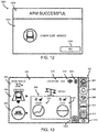
- Fig. 12 shows an embodiment of an arm successful message dialogue 1200 that indicates in a dialogue header portion 1202 that an alarm was able to be armed and further indicates in a dialogue body portion 1204 that the chair exit alarm was successfully armed.
- the arm successful message dialogue 1200 additionally includes a button 1206 to acknowledge the message dialog 1200 and return to the previous screen (e.g., the chair alarm setting screen 900).
- various additional indicators may be added to other screens and/or existing indicators may be updated to include additional information.
- the present alarm state indicator 324 of the home screen 300 of Fig. 3 may be updated to include an indication that the chair exit was armed.
- the home screen 300 may additionally include a silence button 1302 that allows the user to pre-emptively silence the armed alerts from the home screen 300.
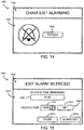
- an embodiment of a chair exit alarming message dialog 1400 includes a dialogue header portion 1402 that indicates the chair exit alarm has been triggered and a dialogue body portion 1404 that provides a silence button 1406 that silences the alert associated with the chair exit alarm.
- Fig. 15 shows an embodiment of an exiting alarm silenced message dialogue 1500 that includes a dialogue header portion 1502 that indicates the message corresponds to a silenced exit alarm and a dialogue body portion 1504.
- the dialogue body portion 1504 includes a time remaining indicator 1506 that provides a countdown that indicates an amount of time remaining until the exit alarm will no longer be silenced.
- the dialogue body portion 1504 additionally includes a silence duration setting interface 1508 that includes a silence time control 1510 to set a dynamically adjustable amount of time for the silence duration and a set silence time button 1512 to set the silence duration to the amount of time represented by the silence time control 1510.
- the silence time control 1510 includes a spinner control
- the silence time control 1510 may be any other type of dynamically adjusted control, such as a drop-down combo-box that includes a predetermined number of time durations from which the user can select.
- the silence duration setting interface 1508 may include a single button with a predetermined static time duration that is set when the user selects (i.e., presses) the single button.
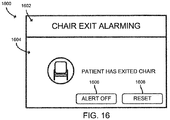
- an embodiment of an alternative chair exit alarming message dialog 1600 includes a dialogue header portion 1602 that indicates the chair exit alarm has been triggered and a dialogue body portion 1604 that provides a more verbose textual indication of the alarm and further provides an alert off button 1606 to turn off the alert associated with the chair exit alarm and a reset button 1608 to reset the alert.
- FIGs. 17 and 18 illustrate embodiments of the various alarms and alerts associated with the stretcher 150 and the toilet 140, respectively.
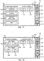
- a stretcher alarm setting screen 1700 that is capable of appearing on the display 222 of the hospital bed 120 is shown.
- the stretcher alarm setting screen 1700 may appear on the display 222 as a result of the user selecting a stretcher exit button (not shown), similar to the bed exit button 406 of Fig. 4 .
- the stretcher alarm setting screen 1700 may include a number of stretcher exit alarm buttons 1702 that correspond to events that may trigger an alarm if armed (i.e., on, active, etc.), and voice alerts 1712 (i.e., audible noises) associated with the stretcher exit alarm buttons 1702 that have been armed. Similar to the bed exit alarm buttons 502 of Fig.
- the illustrative stretcher exit alarm buttons 1702 include a position alarm button 1704 to trigger an alarm when a present position of the stretcher 150 is in a predetermined position (e.g., its lowest position), an exiting alarm button 1706 to trigger an alarm when the user is detected as attempting to exit the stretcher 150, an out of stretcher alarm button 1708 to trigger an alarm when the user is detected as having exited the stretcher 150, and an off button 1710 to turn off (i.e., disarm) all of the stretcher exit alarm buttons 1702.
- the voice alerts 1712 associated with the stretcher exit alarm buttons 1702 may be toggled off via a voice alert off button 1714 or toggled on via a voice alert on button 1716.
- a toilet alarm setting screen 1800 that is capable of appearing on the display 222 of the hospital bed 120 is shown.
- the toilet alarm setting screen 1800 may appear on the display 222 as a result of the user selecting a toilet exit button (not shown), similar to the bed exit button 406 of Fig. 4 .
- the toilet alarm setting screen 1800 may include a number of toilet exit alarms 1802 that correspond to events that may trigger an alarm if armed (i.e., on, active, etc.), and voice alerts 1812 (i.e., audible noises) associated with the toilet exit alarms 1802 that have been armed.
- the illustrative toilet exit alarm buttons 1802 include an on-toilet off button 1804 and an on-toilet on button 1806 to toggle whether an on-toilet alarm is active (i.e., armed).
- the on-toilet alarm toggle buttons 1804, 1806 determine whether the toilet 140 is to monitor for a patient getting on the toilet 140 and provide a signal that indicates to the hospital bed 120 of the patient getting on the toilet 140 upon detection thereof.
- the illustrative toilet exit alarm buttons 1802 include an off-toilet off button 1804 and an off-toilet on button 1806 to toggle whether an off-toilet alarm is active.
- the off-toilet alarm toggle buttons 1808, 1810 determine whether the toilet 140 is to monitor for a patient getting off the toilet 140 and provide a signal that indicates to the hospital bed 120 of the patient exiting the toilet 140 upon detection thereof.
- the voice alerts 1812 associated with the toilet exit alarm buttons 1802 may be toggled off via a voice alert off button 1814 or toggled on via a voice alert on button 1816.
- GUI screens of the hospital bed 120 described herein may be accessed via a remote computing device, such as a computing device of the nurse call system 104 of Fig. 1 .
- a process 1900 for determining whether to provide an alarm signal to the hospital information system 102 of Fig. 1 is shown that may be performed by the hospital bed 120 of Fig. 1 .
- the process 1900 is initialized at step 1902, which may be initiated by a power-on event of the hospital bed 120, for example.
- the process 1900 proceeds to step 1904, to determine whether a falls prevention alarm is active.
- a falls prevention protocol may be enabled at the hospital bed 120 via one or more alerts associated with the hospital bed 120, the other patient supports 110, and/or the other devices 160.
- the process 1900 proceeds to step 1906 to determine which devices (e.g., the other patient supports 110, the other devices 160, etc.) are connected to the hospital bed 120.
- the process 1900 proceeds to step 1908 to determine which alarms are armed based on the connected devices determined at step 1906.
- the process 1900 then proceeds to step 1910 to determine whether at least one falls prevention alarm is active. In other words, to determine whether an alarm has been armed for at least one of the connected devices determined at step 1906. If no falls prevention alarms are active, the process proceeds to step 1912, wherein the process 1900 terminates. If at least one falls prevention alarm is active, the process 1900 proceeds from step 1910 to step 1914 to monitor the hospital bed 120 and any connected devices with armed (i.e., active) alarms determined at block 1908 to detect whether an alarm triggering event was detected. The process 1900 proceeds from step 1914 to step 1916 to determine whether an alarm triggering event was detected based on monitored data corresponding to the armed alarms associated with the hospital bed 120 and/or the other connected devices determined at step 1906.
- step 1918 determines alarm settings based on the triggered falls prevention alarm and which device (e.g., the hospital bed 120 or the other connected devices) triggered the falls prevention alarm.
- step 1920 determines whether in alert is associated with the triggered falls prevention alarm for the triggering device. For example, if the chair exit alarm 902 of Fig. 9 has been activated for the chair 130 of Fig. 1 and was subsequently triggered, an alert may also be associated with the chair exit alarm 902, such as the voice alerts 908 of Fig. 9 , for example.
- the process 1900 proceeds to step 1922 to provide a notification to the nurse call system 104 of Fig.
- a nurse call signal is sent to the nurse call system 104 in response to the chair exit (i.e., the falls prevention alarm).
- the nurse call signal may include an indication to trigger a visible alarm (i.e., an alarm dialog displayed on a computing device, an illuminated LED, a text message sent to a mobile computing device, etc.), and may additionally include an indication to produce a voice alert if the voice alerts 908 have been turned on.
- the process then proceeds from step 1922 to step 1912, wherein the process terminates.
- the one or more other devices 160 may be wirelessly connected to the hospital bed 120.
- the body portion 616 includes the list of devices that are available for pairing with the hospital bed 120 via a Bluetooth connection.
- the presently selected available device 2002 is an "audio communication device" that is indicated as selected by the highlighted rectangle surrounding the available device in the second row of the list of available devices.
- the audio communication device may be an externally located computing device (e.g., a Hill-Rom® SideCom® unit) that is capable of facilitating the reception and transmission of audio communications between the nurse call system 104 and the audio communication device, and/or an audio emitting device (e.g., a radio, a television, etc.) and the audio communication device. Further, the audio communication device is capable of wirelessly transmitting such communications from the audio communication device to a paired device (e.g., the hospital bed 120). As such, upon pairing the audio communication device with the hospital bed 120 (see Fig. 21 ), the speaker 228 of the hospital bed 120 may emit the communications from the nurse call system 104 and/or the audio emitting device.
- a paired device e.g., the hospital bed 120
- the microphone 230 of the hospital bed 120 may receive communications from the patient and wirelessly transmit the audio communications to the audio emitting device for transmission to the nurse call system 104. It should be appreciated that additional and/or alternative externally compatible Bluetooth connections may also be authorized for pairing with the hospital bed 120 via a wireless connection, such as Bluetooth.
Landscapes
- Health & Medical Sciences (AREA)
- Engineering & Computer Science (AREA)
- General Health & Medical Sciences (AREA)
- Life Sciences & Earth Sciences (AREA)
- Physics & Mathematics (AREA)
- Biomedical Technology (AREA)
- Public Health (AREA)
- Business, Economics & Management (AREA)
- Medical Informatics (AREA)
- Veterinary Medicine (AREA)
- Animal Behavior & Ethology (AREA)
- General Physics & Mathematics (AREA)
- Emergency Management (AREA)
- Epidemiology (AREA)
- Molecular Biology (AREA)
- General Business, Economics & Management (AREA)
- Surgery (AREA)
- Biophysics (AREA)
- Pathology (AREA)
- Nursing (AREA)
- Heart & Thoracic Surgery (AREA)
- Primary Health Care (AREA)
- Computer Networks & Wireless Communication (AREA)
- Gerontology & Geriatric Medicine (AREA)
- Electromagnetism (AREA)
- Psychiatry (AREA)
- Psychology (AREA)
- Social Psychology (AREA)
- Oral & Maxillofacial Surgery (AREA)
- Dentistry (AREA)
- Physiology (AREA)
- Child & Adolescent Psychology (AREA)
- Alarm Systems (AREA)
- Accommodation For Nursing Or Treatment Tables (AREA)
- Measuring And Recording Apparatus For Diagnosis (AREA)
Claims (13)
- Eine Patientenstützvorrichtung zur Verwendung in einer Gesundheitseinrichtung mit mindestens einer zweiten Patientenstützvorrichtung, wobei die Patientenstützvorrichtung umfasst:ein Display (222), das für den Benutzer als Schnittstelle zu der grafischen Benutzeroberfläche (GUI) dient und dem Benutzer ermöglicht, einen oder mehrere Alarme einzustellen, wobei jeder Alarm einem alarmauslösenden Ereignis entspricht, das durch eine Aktion eines Patienten ausgelöst wird;einen Kommunikationsschaltkreis (124) zur kommunikativen Kopplung der Patientenstützvorrichtung (120) an ein Gesundheitsversorgungskommunikationssystem (100) und der Patientenstützvorrichtung (120) an mindestens eine zweite Patientenstützvorrichtung (110); undein Steuerungssystem (122) zur Überwachung der Daten der Patientenstützvorrichtung (120) und der mindestens einen zweiten Patientenstützvorrichtung (110) auf Grundlage der eingestellten Alarme, zur Erkennung, ob ein alarmauslösendes Ereignis entweder an der Patientenstützvorrichtung (120) oder an der mindestens einen zweiten Patientenstützvorrichtung (110) auf Grundlage der überwachten Daten eingetreten ist, und als Reaktion auf die Feststellung, dass ein alarmauslösendes Ereignis eingetreten ist, Bereitstellung eines Signals, das auf das alarmauslösende Ereignis hindeutet, an das Gesundheitsversorgungskommunikationssystem (100), dadurch gekennzeichnet, dass der eine oder die mehreren Alarm(e) mindestens einen oder mehrere Alarm(e) der mindestens einen zweiten Patientenstützvorrichtung (110) umfassen.
- Die Patientenstützvorrichtung nach Anspruch 1, wobei das Steuerungssystem (122) der Patientenstützvorrichtung aus den von der zweiten Patientenstützvorrichtung (110) bereitgestellten Informationen ermittelt, ob ein auslösendes Ereignis an der zweiten Patientenstützvorrichtung (110) eingetreten ist, und ein Signal bereitstellt, das darauf hindeutet, dass das alarmauslösende Ereignis an der mindestens einen zweiten Patientenstützvorrichtung (110) eingetreten ist.
- Die Patientenstützvorrichtung nach entweder Anspruch 1 oder Anspruch 2, wobei die mindestens eine zweite Patientenstützvorrichtung mindestens eine von einem Stuhl (130), einer Toilette (140), einer Liege (150) und einem Lifter ist.
- Die Patientenstützvorrichtung nach einem der vorstehenden Ansprüche, wobei die mindestens eine zweite Patientenstützvorrichtung einen Stuhl (130) umfasst, und wobei die Alarme einen Stuhlausstiegsalarm beinhalten, um als Reaktion auf eine Feststellung, dass ein zuvor auf dem Stuhl (130) sitzender Patient derzeit nicht auf dem Stuhl (130) sitzt, einen Alarm auszulösen.
- Die Patientenstützvorrichtung nach einem der vorstehenden Ansprüche, wobei die mindestens eine zweite Patientenstützvorrichtung eine Toilette (140) umfasst, und wobei die Alarme mindestens einen "Auf der Toilette"-Alarm zur Auslösung eines Alarms als Reaktion auf eine Feststellung, dass sich ein Patient auf die Toilette (140) gesetzt hat, und einen "Von der Toilette herunter"-Alarm zur Auslösung eines Alarms als Reaktion auf eine Feststellung beinhalten, dass ein zuvor auf der Toilette (140) sitzender Patient derzeit nicht auf der Toilette (140) sitzt.
- Die Patientenstützvorrichtung nach einem der vorstehenden Ansprüche, wobei die mindestens eine zweite Patientenstützvorrichtung eine Liege (150) umfasst, und wobei die Alarme mindestens einen von einem Positionsalarm zur Auslösung eines Alarms als Reaktion auf eine Feststellung, dass sich eine derzeitige Position der Liege (150) in einer vorgegebenen Position befindet, einen Ausstiegsalarm zur Auslösung eines Alarms als Reaktion auf eine Feststellung, dass ein Versuch des Patienten zum Verlassen der Liege (150) festgestellt wurde, und einen "Außerhalb der Liege"-Alarm zur Auslösung eines Alarms als Reaktion auf eine Feststellung, dass der Patient die Liege (150) verlassen hat, beinhalten.
- Die Patientenstützvorrichtung nach Anspruch 6, wobei die GUI weiterhin so konfiguriert ist, dass der Benutzer die Funktionen der Patientenstützvorrichtung (120) steuern kann.
- Die Patientenstützvorrichtung nach entweder Anspruch 6 oder Anspruch 7, wobei die GUI weiterhin so konfiguriert ist, dass eine drahtlose Netzwerkverbindung zwischen der Patientenstützvorrichtung (120) und der mindestens einen zweiten Patientenstützvorrichtung (110) ermöglicht wird.
- Die Patientenstützvorrichtung nach Anspruch 8, wobei die drahtlose Netzwerkverbindung eine Bluetooth-Netzwerkverbindung umfasst.
- Die Patientenstützvorrichtung nach einem der vorstehenden Ansprüche, wobei die GUI weiterhin so konfiguriert ist, dass auf Grundlage der Alarmeinstellungen mindestens einer mit einer optischen Anzeige und einem hörbaren Geräusch, dass ein alarmauslösendes Ereignis festgestellt wurde, bereitgestellt wird.
- Die Patientenstützvorrichtung nach einem der vorstehenden Ansprüche, wobei die Daten ein vorhandenes Gewicht, das auf die Patientenstützvorrichtung und die mindestens eine zweite Patientenstützvorrichtung aufgebracht wird, umfassen.
- Die Patientenstützvorrichtung nach einem der vorstehenden Ansprüche, wobei das Ereignis, welches das alarmauslösende Ereignis auslösen kann, ein Positionsereignis, ein Ausstiegsereignis und ein "außerhalb der Patientenstützvorrichtung"-Ereignis beinhaltet.
- Die Patientenstützvorrichtung nach einem der vorstehenden Ansprüche, wobei die Patientenstützvorrichtung ein Krankenhausbett (120) ist.
Priority Applications (1)
| Application Number | Priority Date | Filing Date | Title |
|---|---|---|---|
| EP18157931.9A EP3345583B1 (de) | 2015-04-14 | 2016-04-12 | Überwachung von patientenliegen |
Applications Claiming Priority (2)
| Application Number | Priority Date | Filing Date | Title |
|---|---|---|---|
| US201562147239P | 2015-04-14 | 2015-04-14 | |
| US201562187450P | 2015-07-01 | 2015-07-01 |
Related Child Applications (1)
| Application Number | Title | Priority Date | Filing Date |
|---|---|---|---|
| EP18157931.9A Division EP3345583B1 (de) | 2015-04-14 | 2016-04-12 | Überwachung von patientenliegen |
Publications (2)
| Publication Number | Publication Date |
|---|---|
| EP3081203A1 EP3081203A1 (de) | 2016-10-19 |
| EP3081203B1 true EP3081203B1 (de) | 2018-03-14 |
Family
ID=55745670
Family Applications (2)
| Application Number | Title | Priority Date | Filing Date |
|---|---|---|---|
| EP18157931.9A Active EP3345583B1 (de) | 2015-04-14 | 2016-04-12 | Überwachung von patientenliegen |
| EP16164926.4A Active EP3081203B1 (de) | 2015-04-14 | 2016-04-12 | Überwachung von patientenliegen |
Family Applications Before (1)
| Application Number | Title | Priority Date | Filing Date |
|---|---|---|---|
| EP18157931.9A Active EP3345583B1 (de) | 2015-04-14 | 2016-04-12 | Überwachung von patientenliegen |
Country Status (2)
| Country | Link |
|---|---|
| US (2) | US20160307429A1 (de) |
| EP (2) | EP3345583B1 (de) |
Cited By (1)
| Publication number | Priority date | Publication date | Assignee | Title |
|---|---|---|---|---|
| US11684291B2 (en) | 2015-04-14 | 2023-06-27 | Hill-Rom Services, Inc. | Monitoring of patient supports |
Families Citing this family (23)
| Publication number | Priority date | Publication date | Assignee | Title |
|---|---|---|---|---|
| US10004430B2 (en) * | 2014-12-29 | 2018-06-26 | Lg Cns Co., Ltd. | Apparatus and method for detecting a fall |
| US20160338591A1 (en) * | 2015-05-21 | 2016-11-24 | Hill-Rom Services, Inc. | Systems and methods for mitigating tissue breakdown |
| US20170032648A1 (en) * | 2015-07-27 | 2017-02-02 | Eldersafe Technologies, Inc. | Patient monitoring system |
| DE102015113110B4 (de) * | 2015-08-10 | 2019-03-14 | MAQUET GmbH | Ansteuervorrichtung mindestens einer Antriebseinrichtung eines Operationstisches und Verfahren zum Ansteuern |
| US10741284B2 (en) * | 2015-10-02 | 2020-08-11 | Stryker Corporation | Universal calibration system |
| US10489661B1 (en) | 2016-03-08 | 2019-11-26 | Ocuvera LLC | Medical environment monitoring system |
| US10143608B2 (en) * | 2016-09-23 | 2018-12-04 | Stryker Corporation | Systems and methods for determining the usability of person support apparatuses |
| US10600204B1 (en) | 2016-12-28 | 2020-03-24 | Ocuvera | Medical environment bedsore detection and prevention system |
| JP6717235B2 (ja) * | 2017-03-02 | 2020-07-01 | オムロン株式会社 | 見守り支援システム及びその制御方法 |
| US20210254644A1 (en) | 2017-08-03 | 2021-08-19 | Tidi Products, Llc | Integrated Belt and Sensor for Alarm for Patient Furniture |
| US20190304283A1 (en) | 2017-08-03 | 2019-10-03 | Tidi Products, Llc | Integrated Belt And Sensor For Alarm For Patient Furniture |
| US11116680B2 (en) * | 2017-09-19 | 2021-09-14 | Stryker Corporation | Patient support apparatus for controlling patient ingress and egress |
| EP3695414A4 (de) | 2017-10-13 | 2022-08-24 | J. Brasch Co., LLC | Hilfstechnik zum betrieb von pflegeheimen und anderen gesundheitseinrichtungen |
| JP2021515159A (ja) * | 2018-03-08 | 2021-06-17 | リナック エー/エス | リニアアクチュエータ |
| US20200268579A1 (en) * | 2019-02-26 | 2020-08-27 | Hill-Rom Services, Inc. | Bed interface for manual location |
| US11911325B2 (en) * | 2019-02-26 | 2024-02-27 | Hill-Rom Services, Inc. | Bed interface for manual location |
| US11113935B2 (en) * | 2019-04-15 | 2021-09-07 | Stryker Corporation | Patient support apparatuses with nurse call audio management |
| CA3133535A1 (en) * | 2019-06-21 | 2020-12-21 | Stryker Corporation | Patient support apparatus with caregiver reminders |
| US11277476B2 (en) * | 2019-10-18 | 2022-03-15 | Dish Wireless L.L.C. | Internet of things gateway content receiver |
| US11763935B2 (en) * | 2020-01-06 | 2023-09-19 | National Cheng Kung University | Care system for predicting bed exit and patient management system including the same |
| US12042451B2 (en) | 2020-08-21 | 2024-07-23 | Hill-Rom Services, Inc. | Cable-free bed with wireless pillow speaker |
| MX2023012596A (es) | 2021-05-11 | 2023-11-06 | Tidi Products Llc | Sistema y metodo de monitoreo de paciente. |
| US12144608B2 (en) * | 2021-06-22 | 2024-11-19 | Hill-Rom Services, Inc. | Three-mode patient chair exit sensing |
Family Cites Families (16)
| Publication number | Priority date | Publication date | Assignee | Title |
|---|---|---|---|---|
| US7319386B2 (en) * | 2004-08-02 | 2008-01-15 | Hill-Rom Services, Inc. | Configurable system for alerting caregivers |
| US9838836B2 (en) * | 2005-03-29 | 2017-12-05 | Stryker Corporation | Patient support apparatus communication systems |
| US7293487B2 (en) * | 2005-11-15 | 2007-11-13 | 3M Innovative Properties Company | Cutting tool having variable and independent movement in an x-direction and a z-direction into and laterally along a work piece for making microstructures |
| US20080021731A1 (en) * | 2005-12-09 | 2008-01-24 | Valence Broadband, Inc. | Methods and systems for monitoring patient support exiting and initiating response |
| US8572778B2 (en) * | 2007-03-30 | 2013-11-05 | Hill-Rom Services, Inc. | User interface for hospital bed |
| US8334777B2 (en) * | 2010-02-19 | 2012-12-18 | Hill-Rom Services, Inc. | Patient room and bed management apparatus and system |
| US8717181B2 (en) * | 2010-07-29 | 2014-05-06 | Hill-Rom Services, Inc. | Bed exit alert silence with automatic re-enable |
| US9138173B2 (en) * | 2011-09-23 | 2015-09-22 | Hill-Rom Services, Inc. | System for bed and patient mobility device interoperability |
| US9966997B2 (en) * | 2012-09-17 | 2018-05-08 | Stryker Corporation | Communication systems for patient support apparatuses |
| US8866620B2 (en) * | 2012-11-29 | 2014-10-21 | Centrak, Inc. | System and method for fall prevention and detection |
| US9177465B2 (en) * | 2012-12-28 | 2015-11-03 | Hill-Rom Services, Inc. | Bed status system for a patient support apparatus |
| US10290071B2 (en) * | 2013-03-29 | 2019-05-14 | Hill-Rom Services, Inc. | Universal caregiver interface |
| US20150095054A1 (en) * | 2013-09-30 | 2015-04-02 | Newcare Solutions, Llc | Monitoring systems and method |
| US9940810B2 (en) * | 2014-11-19 | 2018-04-10 | Stryker Corporation | Person support apparatuses with patient mobility monitoring |
| US20160235610A1 (en) * | 2015-02-18 | 2016-08-18 | Allen Medical Systems, Inc. | Using patient monitoring data to control a person support apparatus |
| US20160307429A1 (en) | 2015-04-14 | 2016-10-20 | Hill-Rom Services, Inc. | Monitoring of patient supports |
-
2016
- 2016-04-06 US US15/092,082 patent/US20160307429A1/en not_active Abandoned
- 2016-04-12 EP EP18157931.9A patent/EP3345583B1/de active Active
- 2016-04-12 EP EP16164926.4A patent/EP3081203B1/de active Active
-
2021
- 2021-06-28 US US17/360,382 patent/US11684291B2/en active Active
Non-Patent Citations (1)
| Title |
|---|
| None * |
Cited By (1)
| Publication number | Priority date | Publication date | Assignee | Title |
|---|---|---|---|---|
| US11684291B2 (en) | 2015-04-14 | 2023-06-27 | Hill-Rom Services, Inc. | Monitoring of patient supports |
Also Published As
| Publication number | Publication date |
|---|---|
| US20210321908A1 (en) | 2021-10-21 |
| EP3345583B1 (de) | 2020-03-04 |
| US11684291B2 (en) | 2023-06-27 |
| EP3345583A1 (de) | 2018-07-11 |
| US20160307429A1 (en) | 2016-10-20 |
| EP3081203A1 (de) | 2016-10-19 |
Similar Documents
| Publication | Publication Date | Title |
|---|---|---|
| US11684291B2 (en) | Monitoring of patient supports | |
| US10632033B1 (en) | Bed-based safety protocol control | |
| AU2023204224A1 (en) | Patient support apparatuses with wireless headwall communication | |
| JP7581455B2 (ja) | ベッドシステム | |
| US8471697B2 (en) | Systems and methods for remote patient monitoring | |
| EP3162346A1 (de) | Bettwarnungszustandskonfiguration mithilfe einer ferncomputervorrichtung | |
| EP2750060A1 (de) | Bettstatussystem für einen Patientenstützapparat | |
| US20230380769A1 (en) | Bed system | |
| EP3721808B1 (de) | Vorrichtung zur anzeige des kontinenzzustandes eines patienten auf einem bett | |
| EP3880145B1 (de) | Patientenunterstützungsvorrichtungen mit austrittsdetektionssystemen | |
| JP6711474B2 (ja) | システム、システムの制御方法、制御プログラム、およびプログラムを含む装置 | |
| JP5385177B2 (ja) | ナースコールシステム | |
| US20240366446A1 (en) | Patient support apparatus with locking features | |
| US12308129B2 (en) | Access to multiple caregiver information systems | |
| JP6013234B2 (ja) | ナースコールシステム | |
| US20260000367A1 (en) | Patient support apparatus monitoring with alert reduction | |
| JP6744200B2 (ja) | 情報提供システム及び情報提供方法 | |
| WO2026096280A1 (en) | Patient support apparatus with multi-component control | |
| GB2623517A (en) | Resident location monitoring device and method | |
| JP2011172886A (ja) | ナースコールシステム |
Legal Events
| Date | Code | Title | Description |
|---|---|---|---|
| PUAI | Public reference made under article 153(3) epc to a published international application that has entered the european phase |
Free format text: ORIGINAL CODE: 0009012 |
|
| AK | Designated contracting states |
Kind code of ref document: A1 Designated state(s): AL AT BE BG CH CY CZ DE DK EE ES FI FR GB GR HR HU IE IS IT LI LT LU LV MC MK MT NL NO PL PT RO RS SE SI SK SM TR |
|
| AX | Request for extension of the european patent |
Extension state: BA ME |
|
| 17P | Request for examination filed |
Effective date: 20170410 |
|
| RBV | Designated contracting states (corrected) |
Designated state(s): AL AT BE BG CH CY CZ DE DK EE ES FI FR GB GR HR HU IE IS IT LI LT LU LV MC MK MT NL NO PL PT RO RS SE SI SK SM TR |
|
| GRAP | Despatch of communication of intention to grant a patent |
Free format text: ORIGINAL CODE: EPIDOSNIGR1 |
|
| INTG | Intention to grant announced |
Effective date: 20171011 |
|
| GRAS | Grant fee paid |
Free format text: ORIGINAL CODE: EPIDOSNIGR3 |
|
| GRAA | (expected) grant |
Free format text: ORIGINAL CODE: 0009210 |
|
| AK | Designated contracting states |
Kind code of ref document: B1 Designated state(s): AL AT BE BG CH CY CZ DE DK EE ES FI FR GB GR HR HU IE IS IT LI LT LU LV MC MK MT NL NO PL PT RO RS SE SI SK SM TR |
|
| REG | Reference to a national code |
Ref country code: GB Ref legal event code: FG4D |
|
| REG | Reference to a national code |
Ref country code: CH Ref legal event code: EP Ref country code: AT Ref legal event code: REF Ref document number: 978139 Country of ref document: AT Kind code of ref document: T Effective date: 20180315 |
|
| REG | Reference to a national code |
Ref country code: IE Ref legal event code: FG4D |
|
| REG | Reference to a national code |
Ref country code: DE Ref legal event code: R096 Ref document number: 602016001933 Country of ref document: DE |
|
| REG | Reference to a national code |
Ref country code: FR Ref legal event code: PLFP Year of fee payment: 3 |
|
| REG | Reference to a national code |
Ref country code: NL Ref legal event code: MP Effective date: 20180314 |
|
| REG | Reference to a national code |
Ref country code: LT Ref legal event code: MG4D |
|
| PG25 | Lapsed in a contracting state [announced via postgrant information from national office to epo] |
Ref country code: CY Free format text: LAPSE BECAUSE OF FAILURE TO SUBMIT A TRANSLATION OF THE DESCRIPTION OR TO PAY THE FEE WITHIN THE PRESCRIBED TIME-LIMIT Effective date: 20180314 Ref country code: LT Free format text: LAPSE BECAUSE OF FAILURE TO SUBMIT A TRANSLATION OF THE DESCRIPTION OR TO PAY THE FEE WITHIN THE PRESCRIBED TIME-LIMIT Effective date: 20180314 Ref country code: HR Free format text: LAPSE BECAUSE OF FAILURE TO SUBMIT A TRANSLATION OF THE DESCRIPTION OR TO PAY THE FEE WITHIN THE PRESCRIBED TIME-LIMIT Effective date: 20180314 Ref country code: FI Free format text: LAPSE BECAUSE OF FAILURE TO SUBMIT A TRANSLATION OF THE DESCRIPTION OR TO PAY THE FEE WITHIN THE PRESCRIBED TIME-LIMIT Effective date: 20180314 Ref country code: NO Free format text: LAPSE BECAUSE OF FAILURE TO SUBMIT A TRANSLATION OF THE DESCRIPTION OR TO PAY THE FEE WITHIN THE PRESCRIBED TIME-LIMIT Effective date: 20180614 |
|
| REG | Reference to a national code |
Ref country code: AT Ref legal event code: MK05 Ref document number: 978139 Country of ref document: AT Kind code of ref document: T Effective date: 20180314 |
|
| PG25 | Lapsed in a contracting state [announced via postgrant information from national office to epo] |
Ref country code: RS Free format text: LAPSE BECAUSE OF FAILURE TO SUBMIT A TRANSLATION OF THE DESCRIPTION OR TO PAY THE FEE WITHIN THE PRESCRIBED TIME-LIMIT Effective date: 20180314 Ref country code: GR Free format text: LAPSE BECAUSE OF FAILURE TO SUBMIT A TRANSLATION OF THE DESCRIPTION OR TO PAY THE FEE WITHIN THE PRESCRIBED TIME-LIMIT Effective date: 20180615 Ref country code: LV Free format text: LAPSE BECAUSE OF FAILURE TO SUBMIT A TRANSLATION OF THE DESCRIPTION OR TO PAY THE FEE WITHIN THE PRESCRIBED TIME-LIMIT Effective date: 20180314 Ref country code: SE Free format text: LAPSE BECAUSE OF FAILURE TO SUBMIT A TRANSLATION OF THE DESCRIPTION OR TO PAY THE FEE WITHIN THE PRESCRIBED TIME-LIMIT Effective date: 20180314 Ref country code: BG Free format text: LAPSE BECAUSE OF FAILURE TO SUBMIT A TRANSLATION OF THE DESCRIPTION OR TO PAY THE FEE WITHIN THE PRESCRIBED TIME-LIMIT Effective date: 20180614 |
|
| PG25 | Lapsed in a contracting state [announced via postgrant information from national office to epo] |
Ref country code: ES Free format text: LAPSE BECAUSE OF FAILURE TO SUBMIT A TRANSLATION OF THE DESCRIPTION OR TO PAY THE FEE WITHIN THE PRESCRIBED TIME-LIMIT Effective date: 20180314 Ref country code: AL Free format text: LAPSE BECAUSE OF FAILURE TO SUBMIT A TRANSLATION OF THE DESCRIPTION OR TO PAY THE FEE WITHIN THE PRESCRIBED TIME-LIMIT Effective date: 20180314 Ref country code: EE Free format text: LAPSE BECAUSE OF FAILURE TO SUBMIT A TRANSLATION OF THE DESCRIPTION OR TO PAY THE FEE WITHIN THE PRESCRIBED TIME-LIMIT Effective date: 20180314 Ref country code: IT Free format text: LAPSE BECAUSE OF FAILURE TO SUBMIT A TRANSLATION OF THE DESCRIPTION OR TO PAY THE FEE WITHIN THE PRESCRIBED TIME-LIMIT Effective date: 20180314 Ref country code: RO Free format text: LAPSE BECAUSE OF FAILURE TO SUBMIT A TRANSLATION OF THE DESCRIPTION OR TO PAY THE FEE WITHIN THE PRESCRIBED TIME-LIMIT Effective date: 20180314 Ref country code: PL Free format text: LAPSE BECAUSE OF FAILURE TO SUBMIT A TRANSLATION OF THE DESCRIPTION OR TO PAY THE FEE WITHIN THE PRESCRIBED TIME-LIMIT Effective date: 20180314 Ref country code: NL Free format text: LAPSE BECAUSE OF FAILURE TO SUBMIT A TRANSLATION OF THE DESCRIPTION OR TO PAY THE FEE WITHIN THE PRESCRIBED TIME-LIMIT Effective date: 20180314 |
|
| PG25 | Lapsed in a contracting state [announced via postgrant information from national office to epo] |
Ref country code: CZ Free format text: LAPSE BECAUSE OF FAILURE TO SUBMIT A TRANSLATION OF THE DESCRIPTION OR TO PAY THE FEE WITHIN THE PRESCRIBED TIME-LIMIT Effective date: 20180314 Ref country code: SK Free format text: LAPSE BECAUSE OF FAILURE TO SUBMIT A TRANSLATION OF THE DESCRIPTION OR TO PAY THE FEE WITHIN THE PRESCRIBED TIME-LIMIT Effective date: 20180314 Ref country code: AT Free format text: LAPSE BECAUSE OF FAILURE TO SUBMIT A TRANSLATION OF THE DESCRIPTION OR TO PAY THE FEE WITHIN THE PRESCRIBED TIME-LIMIT Effective date: 20180314 Ref country code: SM Free format text: LAPSE BECAUSE OF FAILURE TO SUBMIT A TRANSLATION OF THE DESCRIPTION OR TO PAY THE FEE WITHIN THE PRESCRIBED TIME-LIMIT Effective date: 20180314 |
|
| REG | Reference to a national code |
Ref country code: DE Ref legal event code: R097 Ref document number: 602016001933 Country of ref document: DE |
|
| REG | Reference to a national code |
Ref country code: BE Ref legal event code: MM Effective date: 20180430 |
|
| PG25 | Lapsed in a contracting state [announced via postgrant information from national office to epo] |
Ref country code: PT Free format text: LAPSE BECAUSE OF FAILURE TO SUBMIT A TRANSLATION OF THE DESCRIPTION OR TO PAY THE FEE WITHIN THE PRESCRIBED TIME-LIMIT Effective date: 20180716 |
|
| PLBE | No opposition filed within time limit |
Free format text: ORIGINAL CODE: 0009261 |
|
| STAA | Information on the status of an ep patent application or granted ep patent |
Free format text: STATUS: NO OPPOSITION FILED WITHIN TIME LIMIT |
|
| REG | Reference to a national code |
Ref country code: IE Ref legal event code: MM4A |
|
| PG25 | Lapsed in a contracting state [announced via postgrant information from national office to epo] |
Ref country code: LU Free format text: LAPSE BECAUSE OF NON-PAYMENT OF DUE FEES Effective date: 20180412 Ref country code: DK Free format text: LAPSE BECAUSE OF FAILURE TO SUBMIT A TRANSLATION OF THE DESCRIPTION OR TO PAY THE FEE WITHIN THE PRESCRIBED TIME-LIMIT Effective date: 20180314 Ref country code: MC Free format text: LAPSE BECAUSE OF FAILURE TO SUBMIT A TRANSLATION OF THE DESCRIPTION OR TO PAY THE FEE WITHIN THE PRESCRIBED TIME-LIMIT Effective date: 20180314 |
|
| 26N | No opposition filed |
Effective date: 20181217 |
|
| PG25 | Lapsed in a contracting state [announced via postgrant information from national office to epo] |
Ref country code: SI Free format text: LAPSE BECAUSE OF FAILURE TO SUBMIT A TRANSLATION OF THE DESCRIPTION OR TO PAY THE FEE WITHIN THE PRESCRIBED TIME-LIMIT Effective date: 20180314 Ref country code: BE Free format text: LAPSE BECAUSE OF NON-PAYMENT OF DUE FEES Effective date: 20180430 |
|
| PG25 | Lapsed in a contracting state [announced via postgrant information from national office to epo] |
Ref country code: IE Free format text: LAPSE BECAUSE OF NON-PAYMENT OF DUE FEES Effective date: 20180412 |
|
| REG | Reference to a national code |
Ref country code: CH Ref legal event code: PL |
|
| PG25 | Lapsed in a contracting state [announced via postgrant information from national office to epo] |
Ref country code: LI Free format text: LAPSE BECAUSE OF NON-PAYMENT OF DUE FEES Effective date: 20190430 Ref country code: CH Free format text: LAPSE BECAUSE OF NON-PAYMENT OF DUE FEES Effective date: 20190430 Ref country code: MT Free format text: LAPSE BECAUSE OF NON-PAYMENT OF DUE FEES Effective date: 20180412 |
|
| PG25 | Lapsed in a contracting state [announced via postgrant information from national office to epo] |
Ref country code: TR Free format text: LAPSE BECAUSE OF FAILURE TO SUBMIT A TRANSLATION OF THE DESCRIPTION OR TO PAY THE FEE WITHIN THE PRESCRIBED TIME-LIMIT Effective date: 20180314 |
|
| PG25 | Lapsed in a contracting state [announced via postgrant information from national office to epo] |
Ref country code: HU Free format text: LAPSE BECAUSE OF FAILURE TO SUBMIT A TRANSLATION OF THE DESCRIPTION OR TO PAY THE FEE WITHIN THE PRESCRIBED TIME-LIMIT; INVALID AB INITIO Effective date: 20160412 Ref country code: MK Free format text: LAPSE BECAUSE OF NON-PAYMENT OF DUE FEES Effective date: 20180314 |
|
| PG25 | Lapsed in a contracting state [announced via postgrant information from national office to epo] |
Ref country code: IS Free format text: LAPSE BECAUSE OF FAILURE TO SUBMIT A TRANSLATION OF THE DESCRIPTION OR TO PAY THE FEE WITHIN THE PRESCRIBED TIME-LIMIT Effective date: 20180714 |
|
| PGFP | Annual fee paid to national office [announced via postgrant information from national office to epo] |
Ref country code: DE Payment date: 20250319 Year of fee payment: 10 |
|
| PGFP | Annual fee paid to national office [announced via postgrant information from national office to epo] |
Ref country code: GB Payment date: 20260319 Year of fee payment: 11 |
|
| PGFP | Annual fee paid to national office [announced via postgrant information from national office to epo] |
Ref country code: FR Payment date: 20260320 Year of fee payment: 11 |