EP3081111B1 - Tube-type cosmetics container for discharging liquid contents in drop form - Google Patents
Tube-type cosmetics container for discharging liquid contents in drop form Download PDFInfo
- Publication number
- EP3081111B1 EP3081111B1 EP14869629.7A EP14869629A EP3081111B1 EP 3081111 B1 EP3081111 B1 EP 3081111B1 EP 14869629 A EP14869629 A EP 14869629A EP 3081111 B1 EP3081111 B1 EP 3081111B1
- Authority
- EP
- European Patent Office
- Prior art keywords
- tube
- discharge
- neck
- contents
- discharge control
- Prior art date
- Legal status (The legal status is an assumption and is not a legal conclusion. Google has not performed a legal analysis and makes no representation as to the accuracy of the status listed.)
- Active
Links
Images


Classifications
-
- A—HUMAN NECESSITIES
- A45—HAND OR TRAVELLING ARTICLES
- A45D—HAIRDRESSING OR SHAVING EQUIPMENT; EQUIPMENT FOR COSMETICS OR COSMETIC TREATMENTS, e.g. FOR MANICURING OR PEDICURING
- A45D34/00—Containers or accessories specially adapted for handling liquid toiletry or cosmetic substances, e.g. perfumes
-
- B—PERFORMING OPERATIONS; TRANSPORTING
- B65—CONVEYING; PACKING; STORING; HANDLING THIN OR FILAMENTARY MATERIAL
- B65D—CONTAINERS FOR STORAGE OR TRANSPORT OF ARTICLES OR MATERIALS, e.g. BAGS, BARRELS, BOTTLES, BOXES, CANS, CARTONS, CRATES, DRUMS, JARS, TANKS, HOPPERS, FORWARDING CONTAINERS; ACCESSORIES, CLOSURES, OR FITTINGS THEREFOR; PACKAGING ELEMENTS; PACKAGES
- B65D47/00—Closures with filling and discharging, or with discharging, devices
- B65D47/04—Closures with discharging devices other than pumps
- B65D47/06—Closures with discharging devices other than pumps with pouring spouts or tubes; with discharge nozzles or passages
- B65D47/18—Closures with discharging devices other than pumps with pouring spouts or tubes; with discharge nozzles or passages for discharging drops; Droppers
-
- A—HUMAN NECESSITIES
- A45—HAND OR TRAVELLING ARTICLES
- A45D—HAIRDRESSING OR SHAVING EQUIPMENT; EQUIPMENT FOR COSMETICS OR COSMETIC TREATMENTS, e.g. FOR MANICURING OR PEDICURING
- A45D34/00—Containers or accessories specially adapted for handling liquid toiletry or cosmetic substances, e.g. perfumes
- A45D34/04—Appliances specially adapted for applying liquid, e.g. using roller or ball
-
- B—PERFORMING OPERATIONS; TRANSPORTING
- B65—CONVEYING; PACKING; STORING; HANDLING THIN OR FILAMENTARY MATERIAL
- B65D—CONTAINERS FOR STORAGE OR TRANSPORT OF ARTICLES OR MATERIALS, e.g. BAGS, BARRELS, BOTTLES, BOXES, CANS, CARTONS, CRATES, DRUMS, JARS, TANKS, HOPPERS, FORWARDING CONTAINERS; ACCESSORIES, CLOSURES, OR FITTINGS THEREFOR; PACKAGING ELEMENTS; PACKAGES
- B65D47/00—Closures with filling and discharging, or with discharging, devices
-
- B—PERFORMING OPERATIONS; TRANSPORTING
- B65—CONVEYING; PACKING; STORING; HANDLING THIN OR FILAMENTARY MATERIAL
- B65D—CONTAINERS FOR STORAGE OR TRANSPORT OF ARTICLES OR MATERIALS, e.g. BAGS, BARRELS, BOTTLES, BOXES, CANS, CARTONS, CRATES, DRUMS, JARS, TANKS, HOPPERS, FORWARDING CONTAINERS; ACCESSORIES, CLOSURES, OR FITTINGS THEREFOR; PACKAGING ELEMENTS; PACKAGES
- B65D47/00—Closures with filling and discharging, or with discharging, devices
- B65D47/04—Closures with discharging devices other than pumps
- B65D47/06—Closures with discharging devices other than pumps with pouring spouts or tubes; with discharge nozzles or passages
- B65D47/12—Closures with discharging devices other than pumps with pouring spouts or tubes; with discharge nozzles or passages having removable closures
- B65D47/121—Stoppers
-
- A—HUMAN NECESSITIES
- A45—HAND OR TRAVELLING ARTICLES
- A45D—HAIRDRESSING OR SHAVING EQUIPMENT; EQUIPMENT FOR COSMETICS OR COSMETIC TREATMENTS, e.g. FOR MANICURING OR PEDICURING
- A45D2200/00—Details not otherwise provided for in A45D
- A45D2200/05—Details of containers
- A45D2200/054—Means for supplying liquid to the outlet of the container
-
- B—PERFORMING OPERATIONS; TRANSPORTING
- B65—CONVEYING; PACKING; STORING; HANDLING THIN OR FILAMENTARY MATERIAL
- B65D—CONTAINERS FOR STORAGE OR TRANSPORT OF ARTICLES OR MATERIALS, e.g. BAGS, BARRELS, BOTTLES, BOXES, CANS, CARTONS, CRATES, DRUMS, JARS, TANKS, HOPPERS, FORWARDING CONTAINERS; ACCESSORIES, CLOSURES, OR FITTINGS THEREFOR; PACKAGING ELEMENTS; PACKAGES
- B65D2547/00—Closures with filling and discharging, or with discharging, devices
- B65D2547/04—Closures with discharging devices other than pumps
- B65D2547/06—Closures with discharging devices other than pumps with pouring spouts ot tubes; with discharge nozzles or passages
- B65D2547/063—Details of spouts
- B65D2547/066—Details of spouts inserted in or attached to the base element
Definitions
- the following disclosure relates to a tube-type cosmetic container which discharges a liquid content in a form of droplet, and more particularly, to a tube-type cosmetic container which can reduce the cost burden in accordance with shortening of the manufacturing time and reducing cost, by allowing a liquid content to be discharged in a form of droplet through a simple content discharging structure that becomes gradually wider from a lower portion to an upper portion thereof.
- liquid medicine and artificial tears which are dripped in the eyes for use are contained in a tube-type container and are provided.
- a user pressurizes the tube-type container, liquid contents are uniformly discharged in a form of droplet.
- Korean Utility Model for discharging a liquid content in a form of droplet
- Korean Utility Model Korean Utility Model No. 20-0310084
- Korean Utility Model relates to a tube-type cosmetic container in which a discharge port coupling cap (3) having a discharge hole (3a) is coupled to a discharge port (2) formed on the front end of a tube container (1), and a cap (4) is disposed on and coupled to the discharge port coupling cap (3). Also, a first discharge tube (5) having a discharge hole (5a) is inserted into the discharge port coupling cap (3), and an intermediate outlet tube (6) including a straight-line cutout (6a) at the upper portion thereof and formed of a rubber material is inserted into the first discharge tube (5). Also, an outlet tube (7) having a tube-type shape is inserted into the intermediate outlet tube (6).
- the outlet tube (7) includes a flange (7b) on a lower portion thereof so as to be stopped by a circular stopper (2a) formed in the discharge port (2) of the tube container (1), and has a discharge hole (7c) formed at a center thereof and communicating with the tube container (1).
- Korean Utility Model when the tube container (1) is pressurised by a certain force, contents inside the container move through the discharge hole (7c) of the outlet tube (7), and collect in a space (9). At the same time, the cutout (6a) of the intermediate outlet tube (6) surrounding the outlet tube (7) spreads out, and thus a straight-line gap is generated. In this case, liquid contents collected in the space (9) are converted into a form of droplet while being discharged through the straight-line gap, and are discharged through the discharge hole (5a) of the first discharge tube (5).
- the structure of Korean Utility Model for discharging contents in a form of droplet is complicated, the manufacturing time and cost increase, thereby causing a cost burden of a user.
- WO2004/069679 discloses a tube-type cosmetic container for discharging liquid contents in droplet form, the container comprising a tube body storing contents; a tube neck coupled to an upper portion of the tube body to support the tube body and having an outlet hole such that contents stored in the tube body are discharged therethrough; a discharge control part coupled to an inner side of the tube neck and comprising a discharge control tube which gradually becomes wider from a lower portion to an upper portion of the discharge control tube, the content discharging tube having an upper portion which is formed with the discharge hole and which has a narrower diameter than a lower portion thereof; a content discharging tube coupled to an upper portion of the tube neck and having a discharge hole formed on an upper end of the content discharging tube to discharge contents out of the content discharging tube, the upper end of the discharging tube having a narrower diameter than a lower portion thereof; and an over cap coupled to the tube neck while covering an outer side of the tube neck.
- the present disclosure provides a tube-type cosmetic container which can reduce the cost burden in accordance with shortening of the manufacturing time and reducing cost, by allowing a liquid content to be discharged in a form of droplet through a simple content discharging structure that becomes gradually wider from a lower portion to an upper portion thereof.
- a tube-type cosmetic container can reduce the cost burden in accordance with shortening of the manufacturing time and reducing cost, by allowing a liquid content to be discharged in a form of droplet through a simple content discharging structure that becomes gradually wider from a lower portion to an upper portion thereof.
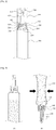
- FIG. 1 is an exploded cross-sectional view illustrating a configuration of a tube-type cosmetic container for discharging liquid contents in a form of droplet according to a first embodiment of the present disclosure.
- FIG. 2 is an assembled cross-sectional view illustrating a configuration of a tube-type cosmetic container for discharging liquid contents in a form of droplet according to a first embodiment of the present disclosure.
- FIG. 3 is a view illustrating a use state of a tube-type cosmetic container for discharging liquid contents in a form of droplet according to a first embodiment of the present disclosure.
- a tube-type cosmetic container for discharging liquid contents in a form of droplet includes a tube body 100, a tube neck 200, a discharge control part 300, a content discharging tube 400, and an over cap 500.
- the tube body 100 may store liquid contents, and may be formed of a flexible material so as to enable contents to be discharged by pressurisation of a user.
- the tube neck 200 is coupled to an upper portion of the tube body 100 to support the tube body 100, and has an outlet hole 210 formed at a central portion thereof such that contents stored in the tube body 100 can be discharged therethrough.
- the tube neck 200 may have a first screw thread 220 which is formed on an upper outer circumferential surface of the tube neck 200 and through which the over cap 500 is screw-coupled to the tube neck 200.
- the discharge control part 300 may be coupled to the inner side of the tube neck 200, and controls the amount of discharge when contents discharged through the outlet hole 210 move upward.
- the discharge control part 300 includes a discharge control tube 310 that is disposed at a central portion thereof and becomes gradually wider from the lower portion to the upper portion thereof.
- the discharge control tube 310 may downwardly extend from the central portion of the upper end of the discharge control part 300 to control the amount of discharge of contents, and becomes gradually wider from the lower portion to the upper portion thereof, enabling contents to drip down in a form of droplet.
- FIG. 3 which illustrates a process of dripping down contents
- a very small amount of contents among contents discharged through the outlet hole 210 may pass through a narrow lower portion of the discharge control tube 310 to be filled in the content discharging tube 400.
- contents gather in the content discharging tube 400, and then are discharged in a form of droplet.
- a seating stopper 320 may be formed to surround the outer circumferential surface of the discharge control part 300 such that a seating protrusion 420 formed at a lower portion of the content discharging tube 400 described later is seated on the seating stopper 320.
- the content discharging tube 400 is coupled to the upper portion of the tube neck 200 to discharge contents to the outside, and has the discharge hole 410 formed on the upper end thereof so as to allow contents to be discharged therethrough.
- the content discharging tube 400 pressurises the discharge control part 300 to allow the discharge control part 300 to be fixed in the tube neck 200.
- the seating protrusion 420 may be formed on the lower portion of the content discharging tube 400 to be seated on the seating stopper 320.
- the content discharging tube 400 is configured with an upper portion, formed with the discharge hole 410, having a narrower diameter than a lower portion thereof.
- the present disclosure is possible to discharge contents drop by drop in a form of droplet without being spurted, though a bit strongly pressurised, due to the structure of the discharge control tube 310 which becomes wider from a lower portion toward an upper portion and the structure of the content discharging tube 400 which forms a narrower diameter in an upper portion than a lower portion.
- the over cap 500 may be detachably coupled to the tube neck 200 while covering the outer side of the tube neck 200, and may have a second screw thread 510 formed on the inner circumferential surface thereof so as to be screw-coupled to the first screw thread 220 of the tube neck 200.
- a closing rod 520 is provided on the undersurface of the upper end of the over cap 500 to close the discharge hole 410 of the content discharging tube 400 and thus prevent leakage of contents.
- a tube-type cosmetic container for discharging liquid contents in a form of droplet does not include the discharge control part 300 for controlling the amount of discharge of contents unlike the first embodiment, and includes a discharge control tube 210' at a central portion of a tube neck 200'.
- the discharge control tube 210' may be integrally formed so as to become wider from a lower portion to an upper portion of the tube neck 200'.
Landscapes
- Engineering & Computer Science (AREA)
- Mechanical Engineering (AREA)
- Containers And Packaging Bodies Having A Special Means To Remove Contents (AREA)
- Closures For Containers (AREA)
Description
- The following disclosure relates to a tube-type cosmetic container which discharges a liquid content in a form of droplet, and more particularly, to a tube-type cosmetic container which can reduce the cost burden in accordance with shortening of the manufacturing time and reducing cost, by allowing a liquid content to be discharged in a form of droplet through a simple content discharging structure that becomes gradually wider from a lower portion to an upper portion thereof.
- Generally, liquid medicine and artificial tears which are dripped in the eyes for use are contained in a tube-type container and are provided. When a user pressurizes the tube-type container, liquid contents are uniformly discharged in a form of droplet.
- For example, a tube-type cosmetic container for discharging a liquid content in a form of droplet is disclosed in Korean Utility Model No.
20-0310084 - Korean Utility Model relates to a tube-type cosmetic container in which a discharge port coupling cap (3) having a discharge hole (3a) is coupled to a discharge port (2) formed on the front end of a tube container (1), and a cap (4) is disposed on and coupled to the discharge port coupling cap (3). Also, a first discharge tube (5) having a discharge hole (5a) is inserted into the discharge port coupling cap (3), and an intermediate outlet tube (6) including a straight-line cutout (6a) at the upper portion thereof and formed of a rubber material is inserted into the first discharge tube (5). Also, an outlet tube (7) having a tube-type shape is inserted into the intermediate outlet tube (6). The outlet tube (7) includes a flange (7b) on a lower portion thereof so as to be stopped by a circular stopper (2a) formed in the discharge port (2) of the tube container (1), and has a discharge hole (7c) formed at a center thereof and communicating with the tube container (1).
- In Korean Utility Model, when the tube container (1) is pressurised by a certain force, contents inside the container move through the discharge hole (7c) of the outlet tube (7), and collect in a space (9). At the same time, the cutout (6a) of the intermediate outlet tube (6) surrounding the outlet tube (7) spreads out, and thus a straight-line gap is generated. In this case, liquid contents collected in the space (9) are converted into a form of droplet while being discharged through the straight-line gap, and are discharged through the discharge hole (5a) of the first discharge tube (5). However, since the structure of Korean Utility Model for discharging contents in a form of droplet is complicated, the manufacturing time and cost increase, thereby causing a cost burden of a user.
-
WO2004/069679 discloses a tube-type cosmetic container for discharging liquid contents in droplet form, the container comprising a tube body storing contents; a tube neck coupled to an upper portion of the tube body to support the tube body and having an outlet hole such that contents stored in the tube body are discharged therethrough; a discharge control part coupled to an inner side of the tube neck and comprising a discharge control tube which gradually becomes wider from a lower portion to an upper portion of the discharge control tube, the content discharging tube having an upper portion which is formed with the discharge hole and which has a narrower diameter than a lower portion thereof; a content discharging tube coupled to an upper portion of the tube neck and having a discharge hole formed on an upper end of the content discharging tube to discharge contents out of the content discharging tube, the upper end of the discharging tube having a narrower diameter than a lower portion thereof; and an over cap coupled to the tube neck while covering an outer side of the tube neck. - Accordingly, the present disclosure provides a tube-type cosmetic container which can reduce the cost burden in accordance with shortening of the manufacturing time and reducing cost, by allowing a liquid content to be discharged in a form of droplet through a simple content discharging structure that becomes gradually wider from a lower portion to an upper portion thereof.
- In accordance with the present invention, there is provided a tube-type cosmetic container of the kind disclosed in
WO2004/069679 which comprises various features of novelty that are identified in the claims appended hereto. - Other features and aspects will be apparent from the following detailed description, the drawings, and the claims.
- According to an embodiment of the present disclosure, a tube-type cosmetic container can reduce the cost burden in accordance with shortening of the manufacturing time and reducing cost, by allowing a liquid content to be discharged in a form of droplet through a simple content discharging structure that becomes gradually wider from a lower portion to an upper portion thereof.
-
-
FIG. 1 is an exploded cross-sectional view illustrating a configuration of a tube-type cosmetic container for discharging liquid contents in a form of droplet according to a first embodiment of the present disclosure. -
FIG. 2 is an assembled cross-sectional view illustrating a configuration of a tube-type cosmetic container for discharging liquid contents in a form of droplet according to a first embodiment of the present disclosure. -
FIG. 3 is a view illustrating a use state of a tube-type cosmetic container for discharging liquid contents in a form of droplet according to a first embodiment of the present disclosure. -
FIG. 4 is an assembled cross-sectional view illustrating a configuration of a tube-type cosmetic container for discharging liquid contents in a form of droplet according to a second embodiment of the present disclosure. - Hereinafter, exemplary embodiments of the present disclosure will be described in detail with reference to the accompanying drawings. The same reference numerals provided in the drawings indicate the same members.
-
FIG. 1 is an exploded cross-sectional view illustrating a configuration of a tube-type cosmetic container for discharging liquid contents in a form of droplet according to a first embodiment of the present disclosure.FIG. 2 is an assembled cross-sectional view illustrating a configuration of a tube-type cosmetic container for discharging liquid contents in a form of droplet according to a first embodiment of the present disclosure.FIG. 3 is a view illustrating a use state of a tube-type cosmetic container for discharging liquid contents in a form of droplet according to a first embodiment of the present disclosure. - Referring to
FIGS. 1 to 3 , a tube-type cosmetic container for discharging liquid contents in a form of droplet according to an exemplary embodiment of the present disclosure
includes atube body 100, atube neck 200, adischarge control part 300, acontent discharging tube 400, and an overcap 500. - The
tube body 100 may store liquid contents, and may be formed of a flexible material so as to enable contents to be discharged by pressurisation of a user. - The
tube neck 200 is coupled to an upper portion of thetube body 100 to support thetube body 100, and has anoutlet hole 210 formed at a central portion thereof such that contents stored in thetube body 100 can be discharged therethrough. - The
tube neck 200 may have afirst screw thread 220 which is formed on an upper outer circumferential surface of thetube neck 200 and through which theover cap 500 is screw-coupled to thetube neck 200. - The
discharge control part 300 may be coupled to the inner side of thetube neck 200, and controls the amount of discharge when contents discharged through theoutlet hole 210 move upward. Thedischarge control part 300 includes adischarge control tube 310 that is disposed at a central portion thereof and becomes gradually wider from the lower portion to the upper portion thereof. - The
discharge control tube 310 may downwardly extend from the central portion of the upper end of thedischarge control part 300 to control the amount of discharge of contents, and becomes gradually wider from the lower portion to the upper portion thereof, enabling contents to drip down in a form of droplet. - As show in
FIG. 3 which illustrates a process of dripping down contents, when a user turns thetube body 100 upside down and then pressurises thetube body 100, a very small amount of contents among contents discharged through theoutlet hole 210 may pass through a narrow lower portion of thedischarge control tube 310 to be filled in thecontent discharging tube 400. When the filling of content in thecontent discharging tube 400 is completed and a certain amount of contents continuously passes the narrow lower portion of thedischarge control tube 310, contents gather in thecontent discharging tube 400, and then are discharged in a form of droplet. - On the other hand, a
seating stopper 320 may be formed to surround the outer circumferential surface of thedischarge control part 300 such that aseating protrusion 420 formed at a lower portion of thecontent discharging tube 400 described later is seated on theseating stopper 320. - The
content discharging tube 400 is coupled to the upper portion of thetube neck 200 to discharge contents to the outside, and has thedischarge hole 410 formed on the upper end thereof so as to allow contents to be discharged therethrough. - The
content discharging tube 400 pressurises thedischarge control part 300 to allow thedischarge control part 300 to be fixed in thetube neck 200. To this end, theseating protrusion 420 may be formed on the lower portion of thecontent discharging tube 400 to be seated on theseating stopper 320. - On the other hand, according to the present disclosure, the
content discharging tube 400 is configured with an upper portion, formed with thedischarge hole 410, having a narrower diameter than a lower portion thereof. - In other words, the present disclosure is possible to discharge contents drop by drop in a form of droplet without being spurted, though a bit strongly pressurised, due to the structure of the
discharge control tube 310 which becomes wider from a lower portion toward an upper portion and the structure of thecontent discharging tube 400 which forms a narrower diameter in an upper portion than a lower portion. - The over
cap 500 may be detachably coupled to thetube neck 200 while covering the outer side of thetube neck 200, and may have asecond screw thread 510 formed on the inner circumferential surface thereof so as to be screw-coupled to thefirst screw thread 220 of thetube neck 200. - Also, a
closing rod 520 is provided on the undersurface of the upper end of the overcap 500 to close thedischarge hole 410 of thecontent discharging tube 400 and thus prevent leakage of contents. - Hereinafter, a tube-type cosmetic container for discharging liquid contents in a form of droplet according to a second embodiment of the present disclosure will be described in detail with reference to
FIG. 4 . - Referring to
FIG. 4 , a tube-type cosmetic container for discharging liquid contents in a form of droplet according to a second embodiment of the present disclosure does not include thedischarge control part 300 for controlling the amount of discharge of contents unlike the first embodiment, and includes a discharge control tube 210' at a central portion of a tube neck 200'. The discharge control tube 210' may be integrally formed so as to become wider from a lower portion to an upper portion of the tube neck 200'. Thus, since thedischarge control part 300 need not be coupled to the inner side of thetube neck 200, the number of parts and the assembly time can be reduced, thereby improving the productivity. - On the other hand, since a tube body 100', a content discharging tube 300', and an over cap 400' are the same as those described in the first embodiment, a detailed description thereof will be omitted herein.
- As described above, optimal embodiments have been disclosed in the drawings and the specification. Although specific terms have been used herein, these are only intended to describe the present disclosure and are not intended to limit the meanings of the terms or to restrict the scope of the present disclosure as disclosed in the accompanying claims. Therefore, those skilled in the art will appreciate that various modifications and other equivalent embodiments are possible from the above embodiments.
Claims (3)
- A tube-type cosmetic container for discharging liquid contents in droplet form, the container comprising:a tube body (100) storing contents;a tube neck (200) coupled to an upper portion of the tube body (100) to support the tube body (100) and having an outlet hole (210) such that contents stored in the tube body (100) are discharged therethrough;a discharge control part (300) coupled to an inner side of the tube neck (200) and comprising a discharge control tube (310) which gradually becomes wider from a lower portion to an upper portion of the discharge control tube (310), the content discharging tube (400) having an upper portion which is formed with the discharge hole (410) and which has a narrower diameter than a lower portion thereof;a content discharging tube (400) coupled to an upper portion of the tube neck (200) and having a discharge hole (410) formed on an upper end of the content discharging tube (400) to discharge contents out of the content discharging tube (400); andan over cap (500) coupled to the tube neck (200) while covering an outer side of the tube neck (200);characterised in that the discharging tube (400) presses the discharge control part (300) downwardly to fix the discharge control part (300) to an inner side of the tube neck (200), the over cap (500) comprising a closing rod (520) for closing the discharge hole (410) of the content discharging tube (400).
- The tube-type cosmetic container of claim 1, characterised in that the discharge control part (300) comprises a seating stopper (320) surrounding an outer circumferential surface of the discharge control part (300) such that a lower portion of the content discharging tube (400) is seated on the seating stopper (320), and the content discharging tube (400) comprises a seating protrusion (420) formed at the lower portion of the content discharging tube (400) and seated on the seating stopper (320).
- A tube-type cosmetic container for discharging liquid contents in droplet form, the container comprising:a tube body (100') storing contents;a tube neck (200') coupled to an upper portion of the tube body (100') to support the tube body (100');a content discharging tube (300') coupled to an upper portion of the tube neck (200') and having a discharge hole (310') formed on an upper end of the content discharging tube (300') so as to discharge contents moving upwardly through the discharge control tube (210') out of the content discharging tube (300'), the content discharging tube (300') having an upper portion which is formed with the discharge hole (310') and which has a narrower diameter than a lower portion thereof; andan over cap (400') coupled to the tube neck (200') while covering an outer side of the tube neck (200');characterised in that the tube neck (200') comprises a discharge control tube (210') which gradually becomes wider from a lower portion to an upper portion of the discharge control tube (210') so as to control the amount of discharge of content stored in the tube body (100') when contents are discharged by pressurisation of the tube body (100'), the over cap (400') comprising a closing rod (420') for closing the discharge hole (310') of the content discharging tube (300').
Applications Claiming Priority (2)
| Application Number | Priority Date | Filing Date | Title |
|---|---|---|---|
| KR1020130152703A KR101554189B1 (en) | 2013-12-10 | 2013-12-10 | Tube type cosmetic vessel exhausting into the form of water drop |
| PCT/KR2014/006821 WO2015088120A1 (en) | 2013-12-10 | 2014-07-25 | Tube-type cosmetics container for discharging liquid contents in drop form |
Publications (3)
| Publication Number | Publication Date |
|---|---|
| EP3081111A1 EP3081111A1 (en) | 2016-10-19 |
| EP3081111A4 EP3081111A4 (en) | 2017-05-03 |
| EP3081111B1 true EP3081111B1 (en) | 2019-01-02 |
Family
ID=53371397
Family Applications (1)
| Application Number | Title | Priority Date | Filing Date |
|---|---|---|---|
| EP14869629.7A Active EP3081111B1 (en) | 2013-12-10 | 2014-07-25 | Tube-type cosmetics container for discharging liquid contents in drop form |
Country Status (7)
| Country | Link |
|---|---|
| US (1) | US10179680B2 (en) |
| EP (1) | EP3081111B1 (en) |
| JP (1) | JP6170251B2 (en) |
| KR (1) | KR101554189B1 (en) |
| CN (2) | CN110250727B (en) |
| ES (1) | ES2708000T3 (en) |
| WO (1) | WO2015088120A1 (en) |
Families Citing this family (18)
| Publication number | Priority date | Publication date | Assignee | Title |
|---|---|---|---|---|
| EP3034428B1 (en) * | 2014-12-19 | 2017-07-19 | SHB GmbH | Dosing cap for a dosing bottle |
| CN106516397A (en) * | 2016-08-30 | 2017-03-22 | 嘉兴市腾翔塑业有限公司 | Liquid cosmetic discharge device |
| ES2753396T3 (en) | 2016-11-17 | 2020-04-08 | Aptar Radolfzell Gmbh | Discharge head and liquid dispenser with such a discharge head |
| DE102016222682B3 (en) * | 2016-11-17 | 2017-10-05 | Aptar Radolfzell Gmbh | Discharge head for a liquid dispenser and liquid dispenser with such a discharge head |
| KR200484966Y1 (en) * | 2017-03-22 | 2017-11-13 | 한국콜마주식회사 | Cosmetic container |
| KR20190033359A (en) | 2017-09-21 | 2019-03-29 | 주식회사 아이팩 | A discharge device for discharging the liquid content in the tube container in a droplet form |
| KR101969461B1 (en) * | 2017-11-30 | 2019-04-16 | (주)연우 | Container for Discharging liquid type contents |
| KR101955208B1 (en) * | 2017-12-18 | 2019-03-07 | 엘앤피코스메틱 (주) | Ampoule for storing cosmetic liquid |
| CN208264912U (en) * | 2018-03-28 | 2018-12-21 | 深圳市通产丽星股份有限公司 | A kind of drop hose |
| TWI708719B (en) * | 2019-02-13 | 2020-11-01 | 陳裕翔 | Nozzle |
| USD902035S1 (en) * | 2019-03-14 | 2020-11-17 | Yonwoo Co., Ltd. | Container for cosmetics |
| KR102076658B1 (en) | 2019-05-31 | 2020-02-13 | 임종수 | A discharge device for discharging the liquid content in the tube container in a droplet form |
| CN110182458A (en) * | 2019-07-02 | 2019-08-30 | 天津贝罗尼生物科技有限公司 | A kind of anti-overflow drop bottle |
| ES3063928T3 (en) | 2021-03-02 | 2026-04-21 | Yonwoo Co Ltd | Container for contents |
| KR102279627B1 (en) | 2021-03-02 | 2021-07-21 | 한국콜마주식회사 | Container |
| US20220312933A1 (en) * | 2021-04-01 | 2022-10-06 | Jiangmen K.K. Plastic Factory Ltd. | Cosmetic container |
| KR102738948B1 (en) * | 2022-11-24 | 2024-12-06 | 주식회사 에프에스코리아 | A cosmetic tool that can accommodate contents in the handle |
| KR102760056B1 (en) * | 2024-11-13 | 2025-02-03 | 주식회사 대산몰드 | Tube-type cosmetic container with ball-type check valve |
Family Cites Families (27)
| Publication number | Priority date | Publication date | Assignee | Title |
|---|---|---|---|---|
| JPH063808Y2 (en) * | 1985-11-27 | 1994-02-02 | ト−メ−産業株式会社 | Secondary contamination prevention cap for eye drops |
| JPS62161657U (en) * | 1986-04-04 | 1987-10-14 | ||
| EP0631770B1 (en) * | 1993-06-25 | 1998-07-22 | Alcon Cusi, S.A. | New use of polymeric membranes in the dispensing of pharmaceutical solutions that contain quaternary ammonium compounds as preservatives and corresponding dose dispensor |
| JPH10278954A (en) * | 1997-04-01 | 1998-10-20 | Lion Corp | Dispensing container |
| US6197008B1 (en) | 1999-05-26 | 2001-03-06 | James Hagele | Precise instilation eye dropper tip |
| AU4075300A (en) | 1999-07-28 | 2001-02-19 | Alcon Laboratories, Inc. | Dropper bottle |
| DE10112332C1 (en) * | 2001-03-13 | 2002-08-29 | Stella Kunststofftechnik Gmbh | Drip cap for dosing liquid in drop form and container with drip cap |
| KR200310084Y1 (en) | 2002-10-04 | 2003-04-08 | 주식회사 태평양 | Tube type cosmetic case exhausting the liquid state contents into the form of bell |
| US8403176B2 (en) * | 2003-01-22 | 2013-03-26 | Allergan, Inc. | Controlled drop dispensing container |
| WO2004069679A1 (en) * | 2003-02-07 | 2004-08-19 | Hoffmann Neopac Ag | Drop dispensing with insert for optimizing the dosing precision of liquids |
| CN1845856A (en) * | 2003-09-02 | 2006-10-11 | 大塚制药株式会社 | Discharge member, discharge container having the discharge member, and instillation container |
| US7063241B2 (en) * | 2004-06-10 | 2006-06-20 | Allergan, Inc. | Dispensing tip |
| US7178703B2 (en) | 2004-11-23 | 2007-02-20 | Allergan, Inc. | Autoclaveable small-volume dropper bottle |
| AU2005324723A1 (en) * | 2005-01-13 | 2006-07-20 | Bormioli Rocco & Figlio S.P.A. | A process for sterile packaging of containers with drop-dispensers, and means for actuating the process |
| JP4796307B2 (en) * | 2005-02-03 | 2011-10-19 | 大成化工株式会社 | Nozzle hole structure for dripping, dripping nozzle having this nozzle hole structure |
| TW200735906A (en) | 2005-11-03 | 2007-10-01 | Rseal Internat Ltd Partnership | Continuously sealing one way valve assembly and fluid delivery system and formulations for use therein |
| US7758553B2 (en) * | 2006-04-03 | 2010-07-20 | Insight Vision Incorporated | Drop dispenser for the delivery of uniform droplets of viscous liquids |
| FR2927064B1 (en) * | 2008-02-04 | 2010-03-26 | Rexam Pharma | LIQUID DISTRIBUTION TIP, AND PACKAGING ASSEMBLY AND LIQUID DISPENSING COMPRISING SUCH A TIP. |
| JP2009249036A (en) | 2008-04-01 | 2009-10-29 | Kitano Seisaku Kk | Dropping inner stopper |
| JP5224915B2 (en) * | 2008-06-03 | 2013-07-03 | 大成化工株式会社 | Discharge container with filter |
| FR2934572A1 (en) * | 2008-07-31 | 2010-02-05 | Thea Lab | BOTTLE FOR FLASK OF LIQUID CONDITIONING TO DISPENSE DROP GOUTTE. |
| KR100903973B1 (en) * | 2009-02-04 | 2009-06-25 | (주)코레드 | Side vacuum pump of pencil type cosmetic container |
| US8695850B2 (en) | 2009-03-06 | 2014-04-15 | Insite Vision Incorporated | Tip arrangement for a dropper bottle |
| KR20100009882U (en) * | 2009-03-31 | 2010-10-08 | (주)톨리코리아 | A airless pump have eye cream cosmetic case |
| US20110297703A1 (en) * | 2010-06-07 | 2011-12-08 | Mccormick & Company, Incorporated | Mess free dispensing nozzle and container with suck back feature |
| GB201013137D0 (en) * | 2010-08-04 | 2010-09-22 | Obrist Closures Switzerland | A closure |
| US20150158050A1 (en) * | 2013-12-05 | 2015-06-11 | Eclectic Products, Inc. | Precision adhesive applicator |
-
2013
- 2013-12-10 KR KR1020130152703A patent/KR101554189B1/en active Active
-
2014
- 2014-07-25 EP EP14869629.7A patent/EP3081111B1/en active Active
- 2014-07-25 JP JP2016539080A patent/JP6170251B2/en active Active
- 2014-07-25 ES ES14869629T patent/ES2708000T3/en active Active
- 2014-07-25 US US15/031,977 patent/US10179680B2/en active Active
- 2014-07-25 CN CN201910507412.7A patent/CN110250727B/en active Active
- 2014-07-25 WO PCT/KR2014/006821 patent/WO2015088120A1/en not_active Ceased
- 2014-07-25 CN CN201480065451.1A patent/CN105873470A/en active Pending
Non-Patent Citations (1)
| Title |
|---|
| None * |
Also Published As
| Publication number | Publication date |
|---|---|
| CN110250727A (en) | 2019-09-20 |
| WO2015088120A1 (en) | 2015-06-18 |
| US20160272381A1 (en) | 2016-09-22 |
| JP2017504379A (en) | 2017-02-09 |
| JP6170251B2 (en) | 2017-07-26 |
| KR20150067412A (en) | 2015-06-18 |
| KR101554189B1 (en) | 2015-09-21 |
| EP3081111A1 (en) | 2016-10-19 |
| US10179680B2 (en) | 2019-01-15 |
| ES2708000T3 (en) | 2019-04-08 |
| CN105873470A (en) | 2016-08-17 |
| CN110250727B (en) | 2022-05-31 |
| EP3081111A4 (en) | 2017-05-03 |
Similar Documents
| Publication | Publication Date | Title |
|---|---|---|
| US10179680B2 (en) | Tube-type cosmetics container for discharging liquid contents in form of droplet | |
| US11447307B2 (en) | Packaging service capsule for cosmetic product, and associated packaging device | |
| EP3718914B1 (en) | Liquid contents discharge container | |
| CN104603019B (en) | For the syringe type vessel lid automatically filled and fixed amount is distributed | |
| US9788633B2 (en) | Extrusion type cosmetic container | |
| WO2020148739A3 (en) | Collapsible travel bottle | |
| KR20180135117A (en) | Combination dispenser and applicator | |
| JP5960037B2 (en) | Foam discharge container | |
| EP2474482B1 (en) | Container with improved opening system | |
| KR101636268B1 (en) | The container containing different kinds of contents | |
| US10595610B2 (en) | Pumping-type cosmetic container having metal applicator | |
| KR200464719Y1 (en) | Mascara case for preventing the rest | |
| KR101730876B1 (en) | Cosmetic vessel capable of easily applying contents | |
| US11470942B2 (en) | Cosmetic container having handling portion | |
| KR200477835Y1 (en) | Solidglue device joined by liquid paste | |
| JP5961536B2 (en) | Bubble container | |
| KR101183895B1 (en) | Cosmetics container | |
| CN210630793U (en) | Cosmetics container of variable pump | |
| KR102150786B1 (en) | A control cap for a discharge volume of a bottle | |
| KR101505034B1 (en) | Cosmetic vessel | |
| CN105832543A (en) | Novel eyedrop bottle | |
| WO2024142708A1 (en) | Liquid dropper container | |
| KR101438181B1 (en) | manicure dualpen | |
| JP2025536146A (en) | Cosmetic tools with handles that can hold contents |
Legal Events
| Date | Code | Title | Description |
|---|---|---|---|
| PUAI | Public reference made under article 153(3) epc to a published international application that has entered the european phase |
Free format text: ORIGINAL CODE: 0009012 |
|
| 17P | Request for examination filed |
Effective date: 20160531 |
|
| AK | Designated contracting states |
Kind code of ref document: A1 Designated state(s): AL AT BE BG CH CY CZ DE DK EE ES FI FR GB GR HR HU IE IS IT LI LT LU LV MC MK MT NL NO PL PT RO RS SE SI SK SM TR |
|
| AX | Request for extension of the european patent |
Extension state: BA ME |
|
| DAX | Request for extension of the european patent (deleted) | ||
| A4 | Supplementary search report drawn up and despatched |
Effective date: 20170330 |
|
| RIC1 | Information provided on ipc code assigned before grant |
Ipc: A45D 34/00 20060101AFI20170325BHEP Ipc: B65D 47/00 20060101ALI20170325BHEP |
|
| STAA | Information on the status of an ep patent application or granted ep patent |
Free format text: STATUS: EXAMINATION IS IN PROGRESS |
|
| 17Q | First examination report despatched |
Effective date: 20180122 |
|
| REG | Reference to a national code |
Ref country code: DE Ref legal event code: R079 Ref document number: 602014039357 Country of ref document: DE Free format text: PREVIOUS MAIN CLASS: A45D0034000000 Ipc: B65D0047180000 |
|
| RIC1 | Information provided on ipc code assigned before grant |
Ipc: B65D 47/18 20060101AFI20180606BHEP |
|
| GRAP | Despatch of communication of intention to grant a patent |
Free format text: ORIGINAL CODE: EPIDOSNIGR1 |
|
| STAA | Information on the status of an ep patent application or granted ep patent |
Free format text: STATUS: GRANT OF PATENT IS INTENDED |
|
| INTG | Intention to grant announced |
Effective date: 20180726 |
|
| GRAS | Grant fee paid |
Free format text: ORIGINAL CODE: EPIDOSNIGR3 |
|
| GRAA | (expected) grant |
Free format text: ORIGINAL CODE: 0009210 |
|
| STAA | Information on the status of an ep patent application or granted ep patent |
Free format text: STATUS: THE PATENT HAS BEEN GRANTED |
|
| AK | Designated contracting states |
Kind code of ref document: B1 Designated state(s): AL AT BE BG CH CY CZ DE DK EE ES FI FR GB GR HR HU IE IS IT LI LT LU LV MC MK MT NL NO PL PT RO RS SE SI SK SM TR |
|
| REG | Reference to a national code |
Ref country code: GB Ref legal event code: FG4D |
|
| REG | Reference to a national code |
Ref country code: CH Ref legal event code: EP Ref country code: AT Ref legal event code: REF Ref document number: 1084082 Country of ref document: AT Kind code of ref document: T Effective date: 20190115 |
|
| REG | Reference to a national code |
Ref country code: IE Ref legal event code: FG4D |
|
| REG | Reference to a national code |
Ref country code: DE Ref legal event code: R096 Ref document number: 602014039357 Country of ref document: DE |
|
| REG | Reference to a national code |
Ref country code: ES Ref legal event code: FG2A Ref document number: 2708000 Country of ref document: ES Kind code of ref document: T3 Effective date: 20190408 |
|
| REG | Reference to a national code |
Ref country code: NL Ref legal event code: MP Effective date: 20190102 |
|
| REG | Reference to a national code |
Ref country code: LT Ref legal event code: MG4D |
|
| REG | Reference to a national code |
Ref country code: AT Ref legal event code: MK05 Ref document number: 1084082 Country of ref document: AT Kind code of ref document: T Effective date: 20190102 |
|
| PG25 | Lapsed in a contracting state [announced via postgrant information from national office to epo] |
Ref country code: NL Free format text: LAPSE BECAUSE OF FAILURE TO SUBMIT A TRANSLATION OF THE DESCRIPTION OR TO PAY THE FEE WITHIN THE PRESCRIBED TIME-LIMIT Effective date: 20190102 |
|
| PG25 | Lapsed in a contracting state [announced via postgrant information from national office to epo] |
Ref country code: FI Free format text: LAPSE BECAUSE OF FAILURE TO SUBMIT A TRANSLATION OF THE DESCRIPTION OR TO PAY THE FEE WITHIN THE PRESCRIBED TIME-LIMIT Effective date: 20190102 Ref country code: SE Free format text: LAPSE BECAUSE OF FAILURE TO SUBMIT A TRANSLATION OF THE DESCRIPTION OR TO PAY THE FEE WITHIN THE PRESCRIBED TIME-LIMIT Effective date: 20190102 Ref country code: NO Free format text: LAPSE BECAUSE OF FAILURE TO SUBMIT A TRANSLATION OF THE DESCRIPTION OR TO PAY THE FEE WITHIN THE PRESCRIBED TIME-LIMIT Effective date: 20190402 Ref country code: PT Free format text: LAPSE BECAUSE OF FAILURE TO SUBMIT A TRANSLATION OF THE DESCRIPTION OR TO PAY THE FEE WITHIN THE PRESCRIBED TIME-LIMIT Effective date: 20190502 Ref country code: LT Free format text: LAPSE BECAUSE OF FAILURE TO SUBMIT A TRANSLATION OF THE DESCRIPTION OR TO PAY THE FEE WITHIN THE PRESCRIBED TIME-LIMIT Effective date: 20190102 Ref country code: PL Free format text: LAPSE BECAUSE OF FAILURE TO SUBMIT A TRANSLATION OF THE DESCRIPTION OR TO PAY THE FEE WITHIN THE PRESCRIBED TIME-LIMIT Effective date: 20190102 |
|
| PG25 | Lapsed in a contracting state [announced via postgrant information from national office to epo] |
Ref country code: HR Free format text: LAPSE BECAUSE OF FAILURE TO SUBMIT A TRANSLATION OF THE DESCRIPTION OR TO PAY THE FEE WITHIN THE PRESCRIBED TIME-LIMIT Effective date: 20190102 Ref country code: RS Free format text: LAPSE BECAUSE OF FAILURE TO SUBMIT A TRANSLATION OF THE DESCRIPTION OR TO PAY THE FEE WITHIN THE PRESCRIBED TIME-LIMIT Effective date: 20190102 Ref country code: BG Free format text: LAPSE BECAUSE OF FAILURE TO SUBMIT A TRANSLATION OF THE DESCRIPTION OR TO PAY THE FEE WITHIN THE PRESCRIBED TIME-LIMIT Effective date: 20190402 Ref country code: GR Free format text: LAPSE BECAUSE OF FAILURE TO SUBMIT A TRANSLATION OF THE DESCRIPTION OR TO PAY THE FEE WITHIN THE PRESCRIBED TIME-LIMIT Effective date: 20190403 Ref country code: LV Free format text: LAPSE BECAUSE OF FAILURE TO SUBMIT A TRANSLATION OF THE DESCRIPTION OR TO PAY THE FEE WITHIN THE PRESCRIBED TIME-LIMIT Effective date: 20190102 Ref country code: IS Free format text: LAPSE BECAUSE OF FAILURE TO SUBMIT A TRANSLATION OF THE DESCRIPTION OR TO PAY THE FEE WITHIN THE PRESCRIBED TIME-LIMIT Effective date: 20190502 |
|
| REG | Reference to a national code |
Ref country code: DE Ref legal event code: R097 Ref document number: 602014039357 Country of ref document: DE |
|
| PG25 | Lapsed in a contracting state [announced via postgrant information from national office to epo] |
Ref country code: EE Free format text: LAPSE BECAUSE OF FAILURE TO SUBMIT A TRANSLATION OF THE DESCRIPTION OR TO PAY THE FEE WITHIN THE PRESCRIBED TIME-LIMIT Effective date: 20190102 Ref country code: RO Free format text: LAPSE BECAUSE OF FAILURE TO SUBMIT A TRANSLATION OF THE DESCRIPTION OR TO PAY THE FEE WITHIN THE PRESCRIBED TIME-LIMIT Effective date: 20190102 Ref country code: SK Free format text: LAPSE BECAUSE OF FAILURE TO SUBMIT A TRANSLATION OF THE DESCRIPTION OR TO PAY THE FEE WITHIN THE PRESCRIBED TIME-LIMIT Effective date: 20190102 Ref country code: AT Free format text: LAPSE BECAUSE OF FAILURE TO SUBMIT A TRANSLATION OF THE DESCRIPTION OR TO PAY THE FEE WITHIN THE PRESCRIBED TIME-LIMIT Effective date: 20190102 Ref country code: IT Free format text: LAPSE BECAUSE OF FAILURE TO SUBMIT A TRANSLATION OF THE DESCRIPTION OR TO PAY THE FEE WITHIN THE PRESCRIBED TIME-LIMIT Effective date: 20190102 Ref country code: DK Free format text: LAPSE BECAUSE OF FAILURE TO SUBMIT A TRANSLATION OF THE DESCRIPTION OR TO PAY THE FEE WITHIN THE PRESCRIBED TIME-LIMIT Effective date: 20190102 Ref country code: AL Free format text: LAPSE BECAUSE OF FAILURE TO SUBMIT A TRANSLATION OF THE DESCRIPTION OR TO PAY THE FEE WITHIN THE PRESCRIBED TIME-LIMIT Effective date: 20190102 Ref country code: CZ Free format text: LAPSE BECAUSE OF FAILURE TO SUBMIT A TRANSLATION OF THE DESCRIPTION OR TO PAY THE FEE WITHIN THE PRESCRIBED TIME-LIMIT Effective date: 20190102 |
|
| PLBE | No opposition filed within time limit |
Free format text: ORIGINAL CODE: 0009261 |
|
| STAA | Information on the status of an ep patent application or granted ep patent |
Free format text: STATUS: NO OPPOSITION FILED WITHIN TIME LIMIT |
|
| PG25 | Lapsed in a contracting state [announced via postgrant information from national office to epo] |
Ref country code: SM Free format text: LAPSE BECAUSE OF FAILURE TO SUBMIT A TRANSLATION OF THE DESCRIPTION OR TO PAY THE FEE WITHIN THE PRESCRIBED TIME-LIMIT Effective date: 20190102 |
|
| 26N | No opposition filed |
Effective date: 20191003 |
|
| PG25 | Lapsed in a contracting state [announced via postgrant information from national office to epo] |
Ref country code: MC Free format text: LAPSE BECAUSE OF FAILURE TO SUBMIT A TRANSLATION OF THE DESCRIPTION OR TO PAY THE FEE WITHIN THE PRESCRIBED TIME-LIMIT Effective date: 20190102 Ref country code: SI Free format text: LAPSE BECAUSE OF FAILURE TO SUBMIT A TRANSLATION OF THE DESCRIPTION OR TO PAY THE FEE WITHIN THE PRESCRIBED TIME-LIMIT Effective date: 20190102 |
|
| REG | Reference to a national code |
Ref country code: CH Ref legal event code: PL |
|
| PG25 | Lapsed in a contracting state [announced via postgrant information from national office to epo] |
Ref country code: TR Free format text: LAPSE BECAUSE OF FAILURE TO SUBMIT A TRANSLATION OF THE DESCRIPTION OR TO PAY THE FEE WITHIN THE PRESCRIBED TIME-LIMIT Effective date: 20190102 |
|
| REG | Reference to a national code |
Ref country code: BE Ref legal event code: MM Effective date: 20190731 |
|
| PG25 | Lapsed in a contracting state [announced via postgrant information from national office to epo] |
Ref country code: LI Free format text: LAPSE BECAUSE OF NON-PAYMENT OF DUE FEES Effective date: 20190731 Ref country code: CH Free format text: LAPSE BECAUSE OF NON-PAYMENT OF DUE FEES Effective date: 20190731 Ref country code: LU Free format text: LAPSE BECAUSE OF NON-PAYMENT OF DUE FEES Effective date: 20190725 Ref country code: BE Free format text: LAPSE BECAUSE OF NON-PAYMENT OF DUE FEES Effective date: 20190731 |
|
| PG25 | Lapsed in a contracting state [announced via postgrant information from national office to epo] |
Ref country code: IE Free format text: LAPSE BECAUSE OF NON-PAYMENT OF DUE FEES Effective date: 20190725 |
|
| PG25 | Lapsed in a contracting state [announced via postgrant information from national office to epo] |
Ref country code: CY Free format text: LAPSE BECAUSE OF FAILURE TO SUBMIT A TRANSLATION OF THE DESCRIPTION OR TO PAY THE FEE WITHIN THE PRESCRIBED TIME-LIMIT Effective date: 20190102 |
|
| PG25 | Lapsed in a contracting state [announced via postgrant information from national office to epo] |
Ref country code: MT Free format text: LAPSE BECAUSE OF FAILURE TO SUBMIT A TRANSLATION OF THE DESCRIPTION OR TO PAY THE FEE WITHIN THE PRESCRIBED TIME-LIMIT Effective date: 20190102 Ref country code: HU Free format text: LAPSE BECAUSE OF FAILURE TO SUBMIT A TRANSLATION OF THE DESCRIPTION OR TO PAY THE FEE WITHIN THE PRESCRIBED TIME-LIMIT; INVALID AB INITIO Effective date: 20140725 |
|
| PG25 | Lapsed in a contracting state [announced via postgrant information from national office to epo] |
Ref country code: MK Free format text: LAPSE BECAUSE OF FAILURE TO SUBMIT A TRANSLATION OF THE DESCRIPTION OR TO PAY THE FEE WITHIN THE PRESCRIBED TIME-LIMIT Effective date: 20190102 |
|
| PGFP | Annual fee paid to national office [announced via postgrant information from national office to epo] |
Ref country code: GB Payment date: 20250605 Year of fee payment: 12 |
|
| PGFP | Annual fee paid to national office [announced via postgrant information from national office to epo] |
Ref country code: FR Payment date: 20250610 Year of fee payment: 12 |
|
| PGFP | Annual fee paid to national office [announced via postgrant information from national office to epo] |
Ref country code: ES Payment date: 20250804 Year of fee payment: 12 |
|
| PGFP | Annual fee paid to national office [announced via postgrant information from national office to epo] |
Ref country code: DE Payment date: 20250604 Year of fee payment: 12 |