EP3080496B1 - Plaque de support d'un moteur dans un corps de vanne - Google Patents
Plaque de support d'un moteur dans un corps de vanne Download PDFInfo
- Publication number
- EP3080496B1 EP3080496B1 EP14827502.7A EP14827502A EP3080496B1 EP 3080496 B1 EP3080496 B1 EP 3080496B1 EP 14827502 A EP14827502 A EP 14827502A EP 3080496 B1 EP3080496 B1 EP 3080496B1
- Authority
- EP
- European Patent Office
- Prior art keywords
- plate
- valve
- motor
- tab
- recess
- Prior art date
- Legal status (The legal status is an assumption and is not a legal conclusion. Google has not performed a legal analysis and makes no representation as to the accuracy of the status listed.)
- Active
Links
Images
Classifications
-
- F—MECHANICAL ENGINEERING; LIGHTING; HEATING; WEAPONS; BLASTING
- F16—ENGINEERING ELEMENTS AND UNITS; GENERAL MEASURES FOR PRODUCING AND MAINTAINING EFFECTIVE FUNCTIONING OF MACHINES OR INSTALLATIONS; THERMAL INSULATION IN GENERAL
- F16K—VALVES; TAPS; COCKS; ACTUATING-FLOATS; DEVICES FOR VENTING OR AERATING
- F16K31/00—Actuating devices; Operating means; Releasing devices
- F16K31/02—Actuating devices; Operating means; Releasing devices electric; magnetic
- F16K31/04—Actuating devices; Operating means; Releasing devices electric; magnetic using a motor
-
- F—MECHANICAL ENGINEERING; LIGHTING; HEATING; WEAPONS; BLASTING
- F02—COMBUSTION ENGINES; HOT-GAS OR COMBUSTION-PRODUCT ENGINE PLANTS
- F02D—CONTROLLING COMBUSTION ENGINES
- F02D9/00—Controlling engines by throttling air or fuel-and-air induction conduits or exhaust conduits
- F02D9/08—Throttle valves specially adapted therefor; Arrangements of such valves in conduits
- F02D9/10—Throttle valves specially adapted therefor; Arrangements of such valves in conduits having pivotally-mounted flaps
- F02D9/1035—Details of the valve housing
-
- F—MECHANICAL ENGINEERING; LIGHTING; HEATING; WEAPONS; BLASTING
- F02—COMBUSTION ENGINES; HOT-GAS OR COMBUSTION-PRODUCT ENGINE PLANTS
- F02D—CONTROLLING COMBUSTION ENGINES
- F02D9/00—Controlling engines by throttling air or fuel-and-air induction conduits or exhaust conduits
- F02D9/08—Throttle valves specially adapted therefor; Arrangements of such valves in conduits
- F02D9/10—Throttle valves specially adapted therefor; Arrangements of such valves in conduits having pivotally-mounted flaps
- F02D9/107—Manufacturing or mounting details
-
- F—MECHANICAL ENGINEERING; LIGHTING; HEATING; WEAPONS; BLASTING
- F02—COMBUSTION ENGINES; HOT-GAS OR COMBUSTION-PRODUCT ENGINE PLANTS
- F02M—SUPPLYING COMBUSTION ENGINES IN GENERAL WITH COMBUSTIBLE MIXTURES OR CONSTITUENTS THEREOF
- F02M26/00—Engine-pertinent apparatus for adding exhaust gases to combustion-air, main fuel or fuel-air mixture, e.g. by exhaust gas recirculation [EGR] systems
- F02M26/52—Systems for actuating EGR valves
- F02M26/53—Systems for actuating EGR valves using electric actuators, e.g. solenoids
- F02M26/54—Rotary actuators, e.g. step motors
-
- F—MECHANICAL ENGINEERING; LIGHTING; HEATING; WEAPONS; BLASTING
- F16—ENGINEERING ELEMENTS AND UNITS; GENERAL MEASURES FOR PRODUCING AND MAINTAINING EFFECTIVE FUNCTIONING OF MACHINES OR INSTALLATIONS; THERMAL INSULATION IN GENERAL
- F16K—VALVES; TAPS; COCKS; ACTUATING-FLOATS; DEVICES FOR VENTING OR AERATING
- F16K27/00—Construction of housing; Use of materials therefor
- F16K27/02—Construction of housing; Use of materials therefor of lift valves
- F16K27/0209—Check valves or pivoted valves
- F16K27/0218—Butterfly valves
-
- F—MECHANICAL ENGINEERING; LIGHTING; HEATING; WEAPONS; BLASTING
- F02—COMBUSTION ENGINES; HOT-GAS OR COMBUSTION-PRODUCT ENGINE PLANTS
- F02D—CONTROLLING COMBUSTION ENGINES
- F02D11/00—Arrangements for, or adaptations to, non-automatic engine control initiation means, e.g. operator initiated
- F02D11/06—Arrangements for, or adaptations to, non-automatic engine control initiation means, e.g. operator initiated characterised by non-mechanical control linkages, e.g. fluid control linkages or by control linkages with power drive or assistance
- F02D11/10—Arrangements for, or adaptations to, non-automatic engine control initiation means, e.g. operator initiated characterised by non-mechanical control linkages, e.g. fluid control linkages or by control linkages with power drive or assistance of the electric type
Definitions
- valve is general and designates any type of device intended to regulate the flow rate and/or the pressure of a fluid, in particular a gas flowing in a driving a plant or a vehicle.
- a valve has a body and implements a member for opening/closing said duct, which may for example be a flap, said flap being moved by a motor housed most of the time in said body.
- this motor is electric and is mounted in the body of the valve by means of a plate integral with said motor, said plate being intended to be housed in a recess of said body.
- This plate is used both to position the motor correctly in said recess of the body and then to fix it to said body in order to be perfectly operational.
- this plate has the double drawback of imposing complex machining of the body in order to allow good indexing of the plate on the body and in particular of introducing play, which is likely to alter the quality of the assembly of the engine in said body. Plates of this type are known in particular in patent applications US6067958A , US2005/092293A and document "Purple Power Rear Mount Sets For Outrunner Motors" by Mx.co.uk .
- the invention relates to a valve comprising a support plate for a motor, which is simple and quick to manufacture and which performs well.
- the valve comprises a body (3) and an actuation assembly (5) comprising a motor (2) and a plate (4), the plate comprising a central body and at least one positioning tongue having a perimeter comprising a portion substantially in a semicircle. Since semicircular machining is easy and quick to perform, the valve body receiving said plate can be manufactured with precision and economically.
- the plate closely matches the shapes of the recess of the body in which it is housed.
- the plate is in one piece, each tab and the central body constituting one and the same piece. Each tab represents a outgrowth of the central body and serves as a guide member to correctly position said plate in the valve. It is assumed that said plate is secured to a motor for actuating the valve, and that it contributes to placing said motor in a perfectly functional position within said valve.
- the plate comprises a first positioning tongue and a second positioning tongue each having a perimeter comprising a substantially semi-circular portion.
- the presence of two tongues increases the rigor and precision of positioning of the plate in the valve by reducing the degrees of freedom of movement of said plate in said valve.
- the plate extends in a plane, the first and second tabs being angularly offset in said plane.
- Each tongue has a rectilinear intermediate portion, connecting the semi-circular portion to the central body.
- the intermediate portion may comprise two rectilinear edges forming between them an angle less than 70°, in particular less than 50°, for example less than 30°.
- the intermediate portion has two substantially parallel rectilinear edges.
- substantially means that the two edges may not be perfectly parallel, an inclination of less than 5° being able to be tolerated between said two edges.
- the valve is intended to receive a valve actuation assembly, comprising a motor and a plate, said plate being fixed to said motor to form a common part.
- a valve actuation assembly comprising a motor and a plate, said plate being fixed to said motor to form a common part.
- the plate is pre-attached to the motor, before the resulting actuator assembly is inserted into the valve.
- Said plate can, for example, be fixed to the motor by crimping.
- the plate and the motor constitute a single piece.
- the motor is used to actuate an opening/closing member valve such as a shutter.
- said motor is an electric motor.
- the motor has an elongated shape and the plate is fixed to one end of said motor, so that the plane of said plate is perpendicular to the longitudinal axis of said motor.
- the plate projects laterally from said engine.
- the body of the valve is provided with a housing and a recess intended to receive an assembly, the motor being placed in the housing and the plate in the recess, the said recess being delimited by a wall of which at least one zone provided to accommodate each tab has a semicircular profile.
- the machining of the recess is simplified by the presence of at least one semi-circular zone, a semi-circular shape being easy to achieve by means of usual and widely proven techniques.
- the wall is made in a foundry and has been machined locally to obtain the semi-circular profile of each zone.
- the wall has at least one indexing pin, in particular two projecting indexing pins intended to guide the insertion of each tab.
- Each pin acts as a guide stop against which the positioning tongue will come to rest to correctly position the plate in the recess.
- the body of the valve is intended to receive an assembly comprising a plate whose tongue has a rectilinear intermediate portion connecting the semi-circular portion to the central body, said rectilinear portion comprising two rectilinear and substantially parallel edges, the two pins of indexing being placed opposite said two edges.
- a valve according to the invention is efficient due to a systematically optimized positioning of the motor, thanks to an adapted geometry of the support plate of said motor and of the recess of said valve intended to receive said plate.
- Such a valve also has the advantage of being easy and quick to manufacture, thanks to the simplified shapes of the support plate. of the motor and of the recess of the valve provided to receive said plate.
- a valve according to the invention has the advantage of being inexpensive due to the ease of manufacturing said plate and the contours of said recess.
- a valve 1 has an opening/closing flap controlled by an electric motor 2, in order to regulate the pressure and the flow rate of a fluid circulating in a conduit.
- a valve can for example be installed in an exhaust gas recirculation (EGR ) circuit of a vehicle engine, to manage the conditions for the passage of the exhaust gases to the air intake circuit of said engine.
- EGR exhaust gas recirculation
- This valve comprises a body 3 provided with a housing for receiving the motor 2 and placing it in an operational position within the valve 1.
- a support plate 4 is fixed to the motor 2 to form an actuation assembly 5.
- This plate 4 is intended to cooperate with the body 3 of the valve 1 with the aim of systematically placing the said motor 2 in an operational position in the said valve 1.
- Motor 2 has a casing 6 of substantially cylindrical shape, the axis of revolution of which constitutes a longitudinal axis of said motor 2.
- One end 7 of casing 6 ends in a lower bearing not visible in the figure, and the other opposite end 8 of this casing 6 is closed off by the support plate 4 .
- This plate 4 is flat and thin, and is oriented on the box 6 so that its plane is perpendicular to the axis of revolution of said box 6.
- This plate 4 has dimensions which are greater than the cross section of the box 6, so that said plate 4 projects laterally from said box 6.
- Plate 4 has two openings 8.9 to allow two rods 10.11 to emerge representing the two electrical poles 8.9 of motor 2, said plate also being crossed by a drive shaft 12 of said motor 2.
- Plate 4 is first fixed to casing 6 of motor 2 by crimping to form actuation assembly 5, said assembly 5 then being implanted in body 3 of valve 1.
- the body 3 of the valve 1 has a housing of substantially cylindrical shape intended to receive the electric motor 2, and a recess 13 provided for inserting the support plate 4, said recess 13 extending said housing and opening towards the outside of the body 3 of the valve 1.
- the actuating assembly 5 is placed in the body 3 of the valve 1, by first inserting the motor 2 into the housing and then positioning the plate 4 in the recess 13 when said motor 2 comes to the end of its travel in said housing.
- the plate 4 has a central body 14 of substantially circular shape and two positioning tabs 15,16 extending said central body 14.
- the central body 14 and the two positioning tabs 15,16 constitute a single piece, which is generally flat and of constant thickness.
- the two tabs 15,16 constitute two protrusions of the central body, which are angularly offset in the plane of the plate 4. These two tongues 15,16 form between them an angle less than or equal to 180° and greater than 100°.
- each positioning tab 15,16 comprises a rectilinear intermediate part 17 and a distal part 18 having a substantially semicircular periphery.
- the intermediate part 17 has two rectilinear edges 19,20 and substantially parallel, and connects the central body 14 of the plate 4 to the distal part 18 of each positioning tongue 15,16.
- These tabs 15,16 are distinguished from the tabs 21 already existing, in that they comprise a rectilinear intermediate part 17 extended by a distal part 18 in the shape of a semicircle, the tabs 21 already existing narrowing gradually and monotonously to end in a distal part in the shape of an arc of a circle less than a semicircle.
- the existing positioning tabs 21 have a fairly indefinite shape, which gradually tapers off without a marking mark.
- Each tongue 15,16 is pierced with an opening 31, so as to allow the passage of a fixing screw 30 to secure the actuating assembly 5 in the body 3 of the valve 1.
- the recess 13 of the body 3 of the valve 1 intended to receive the support plate 4 is formed in a wall 22 in the foundry of said body 3.
- this wall 22 has two specific areas 23, capable of receiving the tabs 15,16 for positioning the plate 4, said two areas 23 being obtained by semi-circular machining of the said wall 22.
- this foundry wall 22 was machined in a complicated way, to adapt to the complex profile of said existing tongues 21.
- Semi-circular machining of this wall 22 is easy and quick to perform because it is carried out in a single operation , and in a reliable and controlled way.
- the positioning tabs 15,16 in the shape of a semicircle of a support plate 4 according to the invention can be ideally inserted into the semicircular zones 23 of the wall 22 of the foundry of the body 3 of the valve. 1, to ensure ideal positioning of said plate 4 in the recess 13 delimited by said wall 22. This ideal positioning takes place without play, and allows the motor 2 to systematically occupy a fully operational position within the body 3 of the valve.
- each pin 24.25 is slightly curved in shape, because it matches the semicircular shape of the area 23 provided to receive the tongue 15.16, and is found opposite one of the two straight edges 19,20 of the intermediate part 17 of a positioning tongue 15,16. These two pins 24,25 are used to position the plate 4 rigorously and precisely in the recess 13.
Landscapes
- Engineering & Computer Science (AREA)
- General Engineering & Computer Science (AREA)
- Mechanical Engineering (AREA)
- Chemical & Material Sciences (AREA)
- Combustion & Propulsion (AREA)
- Manufacturing & Machinery (AREA)
- Electrically Driven Valve-Operating Means (AREA)
Description
- L'invention se rapporte à une vanne telle que défini dans la revendication 1. Le terme « vanne » est général et désigne tout type de dispositif destiné à réguler le débit et/ou la pression d'un fluide, notamment un gaz circulant dans un conduit d'une installation ou d'un véhicule.
- De façon conventionnelle, une vanne possède un corps et met en oeuvre un organe d'ouverture/fermeture dudit conduit, pouvant par exemple être un volet, ledit volet étant mû par un moteur logé la plupart du temps dans ledit corps.
- Habituellement ce moteur est électrique et est monté dans le corps de la vanne au moyen d'une plaque solidaire dudit moteur, ladite plaque étant destinée à venir se loger dans un évidement dudit corps. Cette plaque sert à la fois à positionner correctement le moteur dans ledit évidement du corps puis à le fixer audit corps afin d'être parfaitement opérationnel. Généralement, cette plaque présente le double inconvénient d'imposer un usinage complexe du corps afin de permette une bonne indexation de la plaque sur le corps et d'introduire notamment un jeu, qui est susceptible d'altérer la qualité du montage du moteur dans ledit corps. Il est connu des plaques de ce type notamment dans les demandes de brevet
US6067958A ,US2005/092293A et du document « Purple Power Rear Mount Sets For Outrunner Motors » de Mx.co.uk. - L'invention se rapporte à une vanne comportant une plaque de support d'un moteur, qui est simple et rapide à fabriquer et qui est performante.
- La vanne comporte un corps (3) et un assemblage d'actionnement (5) comprenant un moteur (2) et une plaque (4), la plaque comprenant un corps central et au moins une languette de positionnement ayant un pourtour comportant une portion sensiblement en demi-cercle. Puisqu'un usinage en demi-cercle est facile et rapide à réaliser, le corps de vanne recevant ladite plaque, peut être fabriqué avec précision et de manière économique. De manière avantageuse, la plaque épouse étroitement les formes de l'évidement du corps dans lequel elle est logée. De façon préférentielle, la plaque est monobloc, chaque languette et le corps central constituant une seule et même pièce. Chaque languette représente une excroissance du corps central et sert d'organe de guidage pour placer correctement la dite plaque dans la vanne. Il est supposé que ladite plaque est solidarisée à un moteur d'actionnement de la vanne, et qu'elle contribue à placer ledit moteur dans une position parfaitement fonctionnelle au sein de ladite vanne.
- Avantageusement, la plaque comprend une première languette de positionnement et une deuxième languette de positionnement ayant chacune un pourtour comportant une portion sensiblement en demi-cercle. La présence de deux languettes accroît la rigueur et la précision de positionnement de la plaque dans la vanne en diminuant les degrés de liberté de déplacement de ladite plaque dans ladite vanne.
- De façon préférentielle, la plaque s'étend dans un plan, les première et deuxième languettes étant décalées angulairement dans ledit plan.
- Chaque languette possède une portion intermédiaire rectiligne, reliant la portion en demi-cercle au corps central.
- La portion intermédiaire peut comporter deux bords rectilignes formant entre eux un angle inférieur à 70°, notamment inférieur à 50°, par exemple inférieur à 30°.
- La portion intermédiaire comporte deux bords rectilignes sensiblement parallèles. Le terme « sensiblement » signifie que les deux bords peuvent ne pas être parfaitement parallèles, une inclinaison inférieure à 5° pouvant être tolérée entre lesdits deux bords.
- La vanne est destinée à recevoir un assemblage d'actionnement de vanne, comprenant un moteur et une plaque, ladite plaque étant fixée audit moteur pour former une pièce commune. De cette manière, la plaque est fixée préalablement au moteur, avant que l'assemblage d'actionnement résultant soit inséré dans la vanne. Ladite plaque peut, par exemple, être fixée au moteur par sertissage. Selon un autre mode de réalisation de l'invention, la plaque et le moteur constituent une pièce monobloc. Le moteur sert à actionner un organe d'ouverture/fermeture de la vanne comme par exemple un volet. Préférentiellement ledit moteur est un moteur électrique.
- Avantageusement, le moteur possède une forme allongée et la plaque est fixée à une extrémité dudit moteur, de manière à ce que le plan de ladite plaque soit perpendiculaire à l'axe longitudinal dudit moteur.
- De façon avantageuse, la plaque saille latéralement dudit moteur.
- Le corps de la vanne est doté d'un logement et d'un évidement destinés à recevoir un assemblage, le moteur venant se placer dans le logement et la plaque dans l'évidement, ledit évidement étant délimité par une paroi dont au moins une zone prévue pour loger chaque languette présente un profil en demi-cercle. L'usinage de l'évidement se retrouve simplifié par la présence d'au moins une zone en demi-cercle, une forme en demi-cercle étant facile à réaliser au moyen de techniques usuelles et largement éprouvées.
- Avantageusement, la paroi est réalisée en fonderie et a été localement usinée pour obtenir le profil en demi-cercle de chaque zone.
- De façon préférentielle, la paroi présente au moins un pion d'indexation, notamment deux pions d'indexation en saillie destinés à guider l'insertion de chaque languette. Chaque pion agit comme une butée de guidage contre laquelle va venir s'appuyer la languette de positionnement pour placer correctement la plaque dans l'évidement.
- Préférentiellement, le corps de la vanne est destiné à recevoir un assemblage comportant une plaque dont la languette possède une portion intermédiaire rectiligne reliant la portion en demi-cercle au corps central, ladite portion rectiligne comportant deux bords rectilignes et sensiblement parallèles, les deux pions d'indexation étant placés en regard desdits deux bords.
- Une vanne selon l'invention, est performante en raison d'un positionnement systématiquement optimisé du moteur, grâce à une géométrie adaptée de la plaque de support dudit moteur et de l'évidement de ladite vanne destiné à recevoir ladite plaque. Une telle vanne a de plus l'avantage d'être facile et rapide à fabriquer, grâce aux formes simplifiées de la plaque de support du moteur et de l'évidement de la vanne prévu pour recevoir ladite plaque. Une vanne selon l'invention présente l'avantage d'être peu coûteuse en raison de la facilité à fabriquer ladite plaque et les contours dudit évidement.
- On donne ci-après une description détaillée d'un mode de réalisation préféré d'une plaque de support moteur selon l'invention et d'un corps de vanne destiné à recevoir ladite plaque, en se référant aux
figures 1 à 5 . - la
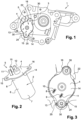
figure 1 est une vue de coté d'une vanne selon l'invention, comprenant un assemblage d'actionnement selon à l'invention, et un corps prévu pour recevoir ledit assemblage, - La
figure 2 est une vue en perspective d'un assemblage d'actionnement selon l'invention, - La
figure 3 est une vue de face d'une plaque de support d'un moteur, ladite plaque et ledit moteur constituant l'assemblage d'actionnement de lafigure 2 , - La
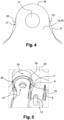
figure 4 est une schématique et comparative d'une languette de positionnement d'une plaque de support de l'état de la technique et d'une plaque support selon l'invention, et - La
figure 5 est une vue en perspective agrandie d'une zone d'un corps de vanne selon l'invention, et destinée à loger une languette de positionnement d'une plaque support selon l'invention. - En se référant à la
figure 1 , une vanne 1 selon l'invention possède un volet d'ouverture/fermeture piloté par un moteur électrique 2, afin de réguler la pression et le débit d'un fluide circulant dans un conduit. Une telle vanne peut par exemple être implantée dans un circuit de recirculation des gaz d'échappement (ou EGR, de l'anglais Exhaust Gas Recirculation) d'un moteur de véhicule, pour gérer les conditions de passage des gaz d'échappement vers le circuit d'admission d'air dudit moteur. Cette vanne comprend un corps 3 doté d'un logement pour recevoir le moteur 2 et le placer dans une position opérationnelle au sein de la vanne 1. - En se référant à la
figure 2 , une plaque 4 de support est fixée au moteur 2 pour former un assemblage d'actionnement 5. Cette plaque 4 est destinée à coopérer avec le corps 3 de la vanne 1 dans le but de placer systématiquement ledit moteur 2 dans une position opérationnelle dans ladite vanne 1. Le moteur 2 possède un boitier 6 de forme sensiblement cylindrique, dont l'axe de révolution constitue un axe longitudinal dudit moteur 2. Une extrémité 7 du boitier 6 se termine par un palier inférieur non visible sur la figure, et l'autre extrémité opposée 8 de ce boitier 6 est obturée par la plaque 4 de support. Cette plaque 4 est plane et de faible épaisseur, et est orientée sur le boitier 6 de manière à ce que son plan soit perpendiculaire à l'axe de révolution dudit boitier 6. Cette plaque 4 possède des dimensions qui sont supérieures à la section transversale du boitier 6, si bien que ladite plaque 4 déborde latéralement dudit boitier 6. La plaque 4 comporte deux ouvertures 8,9 pour laisser émerger deux tiges 10,11 représentant les deux pôles 8,9 électriques du moteur 2, ladite plaque étant également traversée par un arbre d'entrainement 12 dudit moteur 2. - La plaque 4 est d'abord fixée au boitier 6 du moteur 2 par sertissage pour former l'assemblage d'actionnement 5, ledit assemblage 5 étant ensuite implanté dans le corps 3 de la vanne 1.
- En se référant aux
figures 1, 3 et5 le corps 3 de la vanne 1 possède un logement de forme sensiblement cylindrique destiné à recevoir le moteur 2 électrique, et un évidement 13 prévu pour insérer la plaque 4 de support, ledit évidement 13 prolongeant ledit logement et débouchant vers l'extérieur du corps 3 de la vanne 1. L'assemblage d'actionnement 5 est placé dans le corps 3 de la vanne 1, en faisant d'abord pénétrer le moteur 2 dans le logement puis en positionnement la plaque 4 dans l'évidement 13 lorsque ledit moteur 2 arrive en bout de course dans ledit logement. - En se référant à la
figure 3 , la plaque 4 possède un corps central 14 de forme sensiblement circulaire et deux languettes 15,16 de positionnement prolongeant ledit corps central 14. Le corps central 14 et les deux languettes 15,16 de positionnement constituent une seule pièce, qui est globalement plane et d'épaisseur constante. Les deux languettes 15,16 constituent deux excroissances du corps central, qui sont décalées angulairement dans le plan de la plaque 4. Ces deux languettes 15,16 font entre elles un angle inférieur ou égal à 180° et supérieur à 100°. - En se référant à la
figure 4 , chaque languette de positionnement 15,16 comprend une partie intermédiaire 17 rectiligne et une partie distale 18 ayant un pourtour sensiblement en demi-cercle. La partie intermédiaire 17 comporte deux bords rectilignes 19,20 et sensiblement parallèles, et relie le corps central 14 de la plaque 4 à la partie distale 18 de chaque languette de positionnement 15,16. Ces languettes 15,16 se distinguent des languettes 21 déjà existantes, par le fait qu'elles comportent une partie intermédiaire 17 rectiligne prolongée par une partie distale 18 en forme de demi-cercle, les languettes 21 déjà existantes se rétrécissant progressivement et de façon monotone pour se terminer par une partie distale en forme d'arc de cercle inférieur à un demi-cercle. Les languettes de positionnement 21 existantes possède une forme assez indéfinie, qui s'amenuise progressivement sans repère marquant. Chaque languette 15,16 est percée d'une ouverture 31, de manière à permettre le passage d'une vis 30 de fixation pour arrimer l'assemblage d'actionnement 5 dans le corps 3 de la vanne 1. - En se référant aux
figures 1, 3 et5 , l'évidement 13 du corps 3 de la vanne 1 destiné à recevoir la plaque 4 de support, est pratiqué dans une paroi 22 en fonderie dudit corps 3. - En se référant à la
figure 5 , cette paroi 22 comporte deux zones 23 spécifiques, aptes à recevoir les languettes 15,16 de positionnement de la plaque 4, lesdites deux zones 23 étant obtenues par un usinage en demi-cercle de ladite paroi 22. Pour recevoir les languettes de positionnement 21 existantes, cette paroi 22 en fonderie était usinée de façon compliquée, pour s'adapter au profil complexe desdites languettes existantes 21. Un usinage en demi-cercle de cette paroi 22, est facile et rapide à exécuter car il est réalisé en une seule opération, et de façon fiable et maitrisée. Les languettes de positionnement 15,16 en forme de demi-cercle d'une plaque support 4 selon l'invention, peuvent venir s'insérer idéalement dans les zones 23 en demi-cercle de la paroi 22 en fonderie du corps 3 de la vanne 1, pour assurer un positionnement idéal de ladite plaque 4 dans l'évidement 13 délimité par ladite paroi 22. Ce positionnement idéal s'effectue sans jeu, et permet au moteur 2 d'occuper, de façon systématique, une position pleinement opérationnelle au sein du corps 3 de la vanne. - En se référant aux
figures 1, 3 et5 , le positionnement de la plaque 4 dans l'évidement 13 est amélioré par la présence de deux pions 24,25 d'indexage émergeant de chaque zone 23 spécifique dudit évidement 13 prévue pour recevoir une languette de positionnement 15,16. Chaque pion 24,25 est de forme légèrement incurvé, car il épouse la forme en demi-cercle de la zone 23 prévue pour recevoir la languette 15,16, et se retrouve en vis-à-vis de l'un des deux bords rectilignes 19,20 de la partie intermédiaire 17 d'une languette 15,16 de positionnement. Ces deux pions 24,25 servent à positionner rigoureusement et avec précision la plaque 4 dans l'évidement 13. - Un procédé de montage d'un moteur électrique dans une vanne 1 selon l'invention, comprend les étapes suivantes :
- une étape de fixation de la plaque 4 de support à une extrémité du moteur 2 pour obtenir un assemblage d'actionnement 5,
- une étape d'insertion dudit assemblage 5 dans le corps 3 de la vanne au moyen d'une introduction du moteur 2 dans le logement,
- une étape de coulissement de l'assemblage 5 jusqu'à ce qu'une extrémité 7 du moteur 2 arrive au fond du logement et que la plaque 4 parvienne dans l'évidement,
- une étape d'ajustement rotatif de l'assemblage 5 de manière à ce que chaque languette de positionnement 15,16 pénètre dans chaque zone 23 en demi-cercle de la paroi 22 délimitant ledit évidement 13, les deux pions 24,25 devant se retrouver au niveau de chaque partie intermédiaire 17 d'une languette,
- une étape de vissage de l'assemblage d'actionnement 5 ainsi positionné, par l'intermédiaire de deux vis 30 passant par les ouvertures 31 des deux languettes 15,16 de positionnement.
- une étape de vissage de l'assemblage d'actionnement 5 ainsi positionné, par l'intermédiaire de deux vis 30 passant par les ouvertures 31 des deux languettes 15,16 de positionnement.
Claims (10)
- Vanne (1) comportant un corps (3) et un assemblage d'actionnement (5) comprenant un moteur (2) et une plaque (4), la plaque comprenant un corps central (14) et au moins une languette (15,16) de positionnement ayant un pourtour comportant une portion (18) sensiblement en demi-cercle,
caractérisé en ce que chaque languette (15, 16) possède une portion intermédiaire (17) rectiligne, reliant la portion (18) en demi-cercle au corps central (14), la portion intermédiaire (17) comportant deux bords rectilignes (19,20) sensiblement parallèles. - Vanne (1) selon la revendication 1 dans laquelle la plaque comprend une première languette (15) de positionnement et une deuxième languette (16) de positionnement ayant chacune un pourtour comportant une portion (18) sensiblement en demi-cercle.
- Vanne (1) selon la revendication 1 ou 2, la plaque (4) s'étendant dans un plan, et les première et deuxième languettes (15,16) étant (14) décalées angulairement dans ledit plan.
- Vanne (1) selon une des revendications 1 à 3, ladite plaque (4) étant fixée audit moteur (2) pour former une pièce commune.
- Vanne (1) selon une des revendications 1 à 3, dans laquelle le moteur (2) possède une forme allongée et la plaque (4) est fixée à une extrémité (8) dudit moteur (2) de manière à ce que le plan de ladite plaque (4) soit perpendiculaire à l'axe longitudinal dudit moteur (2).
- Vanne (1) selon une la revendication 5, dans laquelle la plaque (4) saille latéralement dudit moteur (2).
- Vanne (1) selon une des revendications 1 à 6, dans laquelle le corps (3) de vanne (1) est doté d'un logement et d'un évidement (13) destinés à recevoir un assemblage (5), le moteur (2) venant se placer dans le logement et la plaque (4) dans l'évidement (13), ledit évidement (13) étant délimité par une paroi (22) dont au moins une zone (23) prévue pour loger chaque languette (15,16) présente un profil en demi-cercle.
- Vanne (1) selon la revendication 7, dans laquelle dans laquelle la paroi (22) est réalisée en fonderie et a été localement usinée pour obtenir le profil en demi-cercle de chaque zone (23).
- Vanne (1) selon une des revendications 7 ou 8, dans laquelle dans laquelle la paroi (22) présente au moins un pion d'indexation (24,25), notamment deux pions (24,25) d'indexation en saillie destinés à guider l'insertion de chaque languette (15,16).
- Vanne (1) selon la revendications 9, dans laquelle le corps est destiné à recevoir l'assemblage (5) comportant la plaque (4), et dans lequel les deux pions (24,25) d'indexation sont placés en regard des deux bords rectilignes (19,20) de la portion intermédiaire (17).
Applications Claiming Priority (2)
| Application Number | Priority Date | Filing Date | Title |
|---|---|---|---|
| FR1362398A FR3014536B1 (fr) | 2013-12-11 | 2013-12-11 | Plaque de support d'un moteur dans un corps de vanne |
| PCT/FR2014/053287 WO2015087008A1 (fr) | 2013-12-11 | 2014-12-11 | Plaque de support d'un moteur dans un corps de vanne |
Publications (2)
| Publication Number | Publication Date |
|---|---|
| EP3080496A1 EP3080496A1 (fr) | 2016-10-19 |
| EP3080496B1 true EP3080496B1 (fr) | 2023-07-19 |
Family
ID=50424463
Family Applications (1)
| Application Number | Title | Priority Date | Filing Date |
|---|---|---|---|
| EP14827502.7A Active EP3080496B1 (fr) | 2013-12-11 | 2014-12-11 | Plaque de support d'un moteur dans un corps de vanne |
Country Status (3)
| Country | Link |
|---|---|
| EP (1) | EP3080496B1 (fr) |
| FR (1) | FR3014536B1 (fr) |
| WO (1) | WO2015087008A1 (fr) |
Family Cites Families (4)
| Publication number | Priority date | Publication date | Assignee | Title |
|---|---|---|---|---|
| JP3404254B2 (ja) * | 1997-05-07 | 2003-05-06 | 株式会社日立製作所 | エンジンのスロットル装置 |
| JP2002339766A (ja) * | 2001-05-15 | 2002-11-27 | Aisan Ind Co Ltd | スロットル弁制御装置 |
| JP4093173B2 (ja) * | 2003-10-31 | 2008-06-04 | 株式会社デンソー | 内燃機関用スロットル制御装置 |
| IT1397318B1 (it) * | 2010-01-12 | 2013-01-10 | Magneti Marelli Spa | Attuatore elettrico per una valvola di un motore termico a combustione interna. |
-
2013
- 2013-12-11 FR FR1362398A patent/FR3014536B1/fr active Active
-
2014
- 2014-12-11 WO PCT/FR2014/053287 patent/WO2015087008A1/fr not_active Ceased
- 2014-12-11 EP EP14827502.7A patent/EP3080496B1/fr active Active
Non-Patent Citations (2)
| Title |
|---|
| 4-MAX.CO.UK: "4-Max for Purple Power Motors", 20 August 2008 (2008-08-20), Retrieved from the Internet <URL:https://web.archive.org/web/20080820050241/http://www.4-max.co.uk/ppb-2831.htm> [retrieved on 20191105] * |
| 4-MAX.CO.UK: "Purple Power Rear Mount SetsFor Outrunner Motors", 17 July 2010 (2010-07-17), Retrieved from the Internet <URL:https://web.archive.org/web/20100717001709/http:/www.4-max.co.uk:80/rearmountsets.htm> [retrieved on 20191105] * |
Also Published As
| Publication number | Publication date |
|---|---|
| FR3014536B1 (fr) | 2016-04-29 |
| EP3080496A1 (fr) | 2016-10-19 |
| WO2015087008A1 (fr) | 2015-06-18 |
| FR3014536A1 (fr) | 2015-06-12 |
Similar Documents
| Publication | Publication Date | Title |
|---|---|---|
| WO2012001282A1 (fr) | Vanne de circulation de fluide | |
| EP2786000B1 (fr) | Procede de montage d'une vanne de controle d'air | |
| WO2011045498A1 (fr) | Bobine d'allumage a noyau magnetique ferme et a aimant permanent et procede de fabrication de la bobine | |
| FR3068304A1 (fr) | Dispositif d'obturation d'entree d'air de face avant de vehicule automobile | |
| EP3172468A1 (fr) | Vanne de circulation de fluide, notamment pour véhicule automobile, à rondelle de butée et procédé de fabrication d'une telle vanne | |
| EP3080497B1 (fr) | Corps de vanne dote d'un logement optimise pour la reception d'un moteur | |
| WO2015087008A1 (fr) | Plaque de support d'un moteur dans un corps de vanne | |
| EP3172470B1 (fr) | Vanne de circulation de fluide, notamment pour véhicule automobile, a logement de réception d'une cible de capteur présentant des nervures | |
| FR2936270A1 (fr) | Dormant equipe d'un dispositif compact de controle automatise ou assiste du pivotement d'un ouvrant | |
| EP3134629B1 (fr) | Vanne de circulation de fluide | |
| FR2987219A1 (fr) | Dispositif de fixation d'un actionneur sur une paroi,notamment une paroi d'une installation de chauffage,ventilation et/ou climatisation | |
| WO2015087010A1 (fr) | Corps de vanne dote d'un logement optimise pour la reception d'un moteur | |
| FR2804740A1 (fr) | Systeme d'obturation pour canalisation de fluide | |
| EP2539722B1 (fr) | Boîtier avec une face arrière destine a etre fixe sur un support | |
| EP2895728B1 (fr) | Vanne de circulation d'un fluide, en particulier gaz d'echappement recircule | |
| WO2018224386A1 (fr) | Actionneur pour dispositif de regulation d'entree d'air pour vehicule automobile | |
| EP3523164B1 (fr) | Roue dentée pour un motoréducteur d'essuie-glace | |
| WO2015162381A1 (fr) | Vanne de circulation de fluide | |
| WO2024179997A1 (fr) | Dispositif d'actionnement électromécanique pour une vanne de distribution de fluide | |
| FR3056465A1 (fr) | Actionneur pour dispositif de controle d'entree d'air pour vehicule automobile | |
| EP3090168B1 (fr) | Élément de vanne, notamment pour moteur thermique | |
| FR3065505A1 (fr) | Dispositif d'entrainement en rotation et vanne de circulation de fluide le comprenant | |
| FR2853459A1 (fr) | Connecteur electrique | |
| FR3010496A1 (fr) | Groupe moto-ventilateur a montage optimise, notamment pour un vehicule automobile. | |
| EP3747112A1 (fr) | Dispositif d'actionnement comportant un moteur electrique et vanne de circulation de fluide le comportant |
Legal Events
| Date | Code | Title | Description |
|---|---|---|---|
| PUAI | Public reference made under article 153(3) epc to a published international application that has entered the european phase |
Free format text: ORIGINAL CODE: 0009012 |
|
| 17P | Request for examination filed |
Effective date: 20160607 |
|
| AK | Designated contracting states |
Kind code of ref document: A1 Designated state(s): AL AT BE BG CH CY CZ DE DK EE ES FI FR GB GR HR HU IE IS IT LI LT LU LV MC MK MT NL NO PL PT RO RS SE SI SK SM TR |
|
| AX | Request for extension of the european patent |
Extension state: BA ME |
|
| DAX | Request for extension of the european patent (deleted) | ||
| STAA | Information on the status of an ep patent application or granted ep patent |
Free format text: STATUS: EXAMINATION IS IN PROGRESS |
|
| 17Q | First examination report despatched |
Effective date: 20180313 |
|
| GRAP | Despatch of communication of intention to grant a patent |
Free format text: ORIGINAL CODE: EPIDOSNIGR1 |
|
| STAA | Information on the status of an ep patent application or granted ep patent |
Free format text: STATUS: GRANT OF PATENT IS INTENDED |
|
| RIC1 | Information provided on ipc code assigned before grant |
Ipc: F16K 27/02 19680901AFI20230106BHEP Ipc: F02M 26/54 20160101ALI20230106BHEP Ipc: F02D 11/10 19680901ALI20230106BHEP Ipc: H02K 5/04 19680901ALI20230106BHEP Ipc: F16K 31/04 19680901ALI20230106BHEP Ipc: F02D 9/10 19680901ALI20230106BHEP |
|
| INTG | Intention to grant announced |
Effective date: 20230207 |
|
| GRAS | Grant fee paid |
Free format text: ORIGINAL CODE: EPIDOSNIGR3 |
|
| GRAA | (expected) grant |
Free format text: ORIGINAL CODE: 0009210 |
|
| STAA | Information on the status of an ep patent application or granted ep patent |
Free format text: STATUS: THE PATENT HAS BEEN GRANTED |
|
| P01 | Opt-out of the competence of the unified patent court (upc) registered |
Effective date: 20230528 |
|
| AK | Designated contracting states |
Kind code of ref document: B1 Designated state(s): AL AT BE BG CH CY CZ DE DK EE ES FI FR GB GR HR HU IE IS IT LI LT LU LV MC MK MT NL NO PL PT RO RS SE SI SK SM TR |
|
| REG | Reference to a national code |
Ref country code: GB Ref legal event code: FG4D Free format text: NOT ENGLISH |
|
| REG | Reference to a national code |
Ref country code: CH Ref legal event code: EP |
|
| REG | Reference to a national code |
Ref country code: DE Ref legal event code: R096 Ref document number: 602014087695 Country of ref document: DE |
|
| REG | Reference to a national code |
Ref country code: IE Ref legal event code: FG4D Free format text: LANGUAGE OF EP DOCUMENT: FRENCH |
|
| REG | Reference to a national code |
Ref country code: LT Ref legal event code: MG9D |
|
| REG | Reference to a national code |
Ref country code: NL Ref legal event code: MP Effective date: 20230719 |
|
| REG | Reference to a national code |
Ref country code: AT Ref legal event code: MK05 Ref document number: 1589780 Country of ref document: AT Kind code of ref document: T Effective date: 20230719 |
|
| PG25 | Lapsed in a contracting state [announced via postgrant information from national office to epo] |
Ref country code: NL Free format text: LAPSE BECAUSE OF FAILURE TO SUBMIT A TRANSLATION OF THE DESCRIPTION OR TO PAY THE FEE WITHIN THE PRESCRIBED TIME-LIMIT Effective date: 20230719 |
|
| PG25 | Lapsed in a contracting state [announced via postgrant information from national office to epo] |
Ref country code: GR Free format text: LAPSE BECAUSE OF FAILURE TO SUBMIT A TRANSLATION OF THE DESCRIPTION OR TO PAY THE FEE WITHIN THE PRESCRIBED TIME-LIMIT Effective date: 20231020 |
|
| PG25 | Lapsed in a contracting state [announced via postgrant information from national office to epo] |
Ref country code: IS Free format text: LAPSE BECAUSE OF FAILURE TO SUBMIT A TRANSLATION OF THE DESCRIPTION OR TO PAY THE FEE WITHIN THE PRESCRIBED TIME-LIMIT Effective date: 20231119 |
|
| PG25 | Lapsed in a contracting state [announced via postgrant information from national office to epo] |
Ref country code: SE Free format text: LAPSE BECAUSE OF FAILURE TO SUBMIT A TRANSLATION OF THE DESCRIPTION OR TO PAY THE FEE WITHIN THE PRESCRIBED TIME-LIMIT Effective date: 20230719 Ref country code: RS Free format text: LAPSE BECAUSE OF FAILURE TO SUBMIT A TRANSLATION OF THE DESCRIPTION OR TO PAY THE FEE WITHIN THE PRESCRIBED TIME-LIMIT Effective date: 20230719 Ref country code: PT Free format text: LAPSE BECAUSE OF FAILURE TO SUBMIT A TRANSLATION OF THE DESCRIPTION OR TO PAY THE FEE WITHIN THE PRESCRIBED TIME-LIMIT Effective date: 20231120 Ref country code: NO Free format text: LAPSE BECAUSE OF FAILURE TO SUBMIT A TRANSLATION OF THE DESCRIPTION OR TO PAY THE FEE WITHIN THE PRESCRIBED TIME-LIMIT Effective date: 20231019 Ref country code: LV Free format text: LAPSE BECAUSE OF FAILURE TO SUBMIT A TRANSLATION OF THE DESCRIPTION OR TO PAY THE FEE WITHIN THE PRESCRIBED TIME-LIMIT Effective date: 20230719 Ref country code: LT Free format text: LAPSE BECAUSE OF FAILURE TO SUBMIT A TRANSLATION OF THE DESCRIPTION OR TO PAY THE FEE WITHIN THE PRESCRIBED TIME-LIMIT Effective date: 20230719 Ref country code: IS Free format text: LAPSE BECAUSE OF FAILURE TO SUBMIT A TRANSLATION OF THE DESCRIPTION OR TO PAY THE FEE WITHIN THE PRESCRIBED TIME-LIMIT Effective date: 20231119 Ref country code: HR Free format text: LAPSE BECAUSE OF FAILURE TO SUBMIT A TRANSLATION OF THE DESCRIPTION OR TO PAY THE FEE WITHIN THE PRESCRIBED TIME-LIMIT Effective date: 20230719 Ref country code: GR Free format text: LAPSE BECAUSE OF FAILURE TO SUBMIT A TRANSLATION OF THE DESCRIPTION OR TO PAY THE FEE WITHIN THE PRESCRIBED TIME-LIMIT Effective date: 20231020 Ref country code: FI Free format text: LAPSE BECAUSE OF FAILURE TO SUBMIT A TRANSLATION OF THE DESCRIPTION OR TO PAY THE FEE WITHIN THE PRESCRIBED TIME-LIMIT Effective date: 20230719 Ref country code: AT Free format text: LAPSE BECAUSE OF FAILURE TO SUBMIT A TRANSLATION OF THE DESCRIPTION OR TO PAY THE FEE WITHIN THE PRESCRIBED TIME-LIMIT Effective date: 20230719 |
|
| PG25 | Lapsed in a contracting state [announced via postgrant information from national office to epo] |
Ref country code: PL Free format text: LAPSE BECAUSE OF FAILURE TO SUBMIT A TRANSLATION OF THE DESCRIPTION OR TO PAY THE FEE WITHIN THE PRESCRIBED TIME-LIMIT Effective date: 20230719 |
|
| REG | Reference to a national code |
Ref country code: DE Ref legal event code: R097 Ref document number: 602014087695 Country of ref document: DE |
|
| PG25 | Lapsed in a contracting state [announced via postgrant information from national office to epo] |
Ref country code: ES Free format text: LAPSE BECAUSE OF FAILURE TO SUBMIT A TRANSLATION OF THE DESCRIPTION OR TO PAY THE FEE WITHIN THE PRESCRIBED TIME-LIMIT Effective date: 20230719 |
|
| PG25 | Lapsed in a contracting state [announced via postgrant information from national office to epo] |
Ref country code: SM Free format text: LAPSE BECAUSE OF FAILURE TO SUBMIT A TRANSLATION OF THE DESCRIPTION OR TO PAY THE FEE WITHIN THE PRESCRIBED TIME-LIMIT Effective date: 20230719 Ref country code: RO Free format text: LAPSE BECAUSE OF FAILURE TO SUBMIT A TRANSLATION OF THE DESCRIPTION OR TO PAY THE FEE WITHIN THE PRESCRIBED TIME-LIMIT Effective date: 20230719 Ref country code: ES Free format text: LAPSE BECAUSE OF FAILURE TO SUBMIT A TRANSLATION OF THE DESCRIPTION OR TO PAY THE FEE WITHIN THE PRESCRIBED TIME-LIMIT Effective date: 20230719 Ref country code: EE Free format text: LAPSE BECAUSE OF FAILURE TO SUBMIT A TRANSLATION OF THE DESCRIPTION OR TO PAY THE FEE WITHIN THE PRESCRIBED TIME-LIMIT Effective date: 20230719 Ref country code: DK Free format text: LAPSE BECAUSE OF FAILURE TO SUBMIT A TRANSLATION OF THE DESCRIPTION OR TO PAY THE FEE WITHIN THE PRESCRIBED TIME-LIMIT Effective date: 20230719 Ref country code: CZ Free format text: LAPSE BECAUSE OF FAILURE TO SUBMIT A TRANSLATION OF THE DESCRIPTION OR TO PAY THE FEE WITHIN THE PRESCRIBED TIME-LIMIT Effective date: 20230719 Ref country code: SK Free format text: LAPSE BECAUSE OF FAILURE TO SUBMIT A TRANSLATION OF THE DESCRIPTION OR TO PAY THE FEE WITHIN THE PRESCRIBED TIME-LIMIT Effective date: 20230719 |
|
| PLBE | No opposition filed within time limit |
Free format text: ORIGINAL CODE: 0009261 |
|
| STAA | Information on the status of an ep patent application or granted ep patent |
Free format text: STATUS: NO OPPOSITION FILED WITHIN TIME LIMIT |
|
| PG25 | Lapsed in a contracting state [announced via postgrant information from national office to epo] |
Ref country code: IT Free format text: LAPSE BECAUSE OF FAILURE TO SUBMIT A TRANSLATION OF THE DESCRIPTION OR TO PAY THE FEE WITHIN THE PRESCRIBED TIME-LIMIT Effective date: 20230719 |
|
| 26N | No opposition filed |
Effective date: 20240422 |
|
| PG25 | Lapsed in a contracting state [announced via postgrant information from national office to epo] |
Ref country code: SI Free format text: LAPSE BECAUSE OF FAILURE TO SUBMIT A TRANSLATION OF THE DESCRIPTION OR TO PAY THE FEE WITHIN THE PRESCRIBED TIME-LIMIT Effective date: 20230719 |
|
| REG | Reference to a national code |
Ref country code: CH Ref legal event code: PL |
|
| PG25 | Lapsed in a contracting state [announced via postgrant information from national office to epo] |
Ref country code: LU Free format text: LAPSE BECAUSE OF NON-PAYMENT OF DUE FEES Effective date: 20231211 |
|
| PG25 | Lapsed in a contracting state [announced via postgrant information from national office to epo] |
Ref country code: MC Free format text: LAPSE BECAUSE OF FAILURE TO SUBMIT A TRANSLATION OF THE DESCRIPTION OR TO PAY THE FEE WITHIN THE PRESCRIBED TIME-LIMIT Effective date: 20230719 |
|
| GBPC | Gb: european patent ceased through non-payment of renewal fee |
Effective date: 20231211 |
|
| REG | Reference to a national code |
Ref country code: BE Ref legal event code: MM Effective date: 20231231 |
|
| PG25 | Lapsed in a contracting state [announced via postgrant information from national office to epo] |
Ref country code: MC Free format text: LAPSE BECAUSE OF FAILURE TO SUBMIT A TRANSLATION OF THE DESCRIPTION OR TO PAY THE FEE WITHIN THE PRESCRIBED TIME-LIMIT Effective date: 20230719 Ref country code: LU Free format text: LAPSE BECAUSE OF NON-PAYMENT OF DUE FEES Effective date: 20231211 |
|
| REG | Reference to a national code |
Ref country code: IE Ref legal event code: MM4A |
|
| PG25 | Lapsed in a contracting state [announced via postgrant information from national office to epo] |
Ref country code: IE Free format text: LAPSE BECAUSE OF NON-PAYMENT OF DUE FEES Effective date: 20231211 |
|
| PG25 | Lapsed in a contracting state [announced via postgrant information from national office to epo] |
Ref country code: GB Free format text: LAPSE BECAUSE OF NON-PAYMENT OF DUE FEES Effective date: 20231211 |
|
| PG25 | Lapsed in a contracting state [announced via postgrant information from national office to epo] |
Ref country code: BE Free format text: LAPSE BECAUSE OF NON-PAYMENT OF DUE FEES Effective date: 20231231 |
|
| PG25 | Lapsed in a contracting state [announced via postgrant information from national office to epo] |
Ref country code: CH Free format text: LAPSE BECAUSE OF NON-PAYMENT OF DUE FEES Effective date: 20231231 |
|
| PG25 | Lapsed in a contracting state [announced via postgrant information from national office to epo] |
Ref country code: IE Free format text: LAPSE BECAUSE OF NON-PAYMENT OF DUE FEES Effective date: 20231211 Ref country code: GB Free format text: LAPSE BECAUSE OF NON-PAYMENT OF DUE FEES Effective date: 20231211 Ref country code: CH Free format text: LAPSE BECAUSE OF NON-PAYMENT OF DUE FEES Effective date: 20231231 Ref country code: BE Free format text: LAPSE BECAUSE OF NON-PAYMENT OF DUE FEES Effective date: 20231231 |
|
| PG25 | Lapsed in a contracting state [announced via postgrant information from national office to epo] |
Ref country code: BG Free format text: LAPSE BECAUSE OF FAILURE TO SUBMIT A TRANSLATION OF THE DESCRIPTION OR TO PAY THE FEE WITHIN THE PRESCRIBED TIME-LIMIT Effective date: 20230719 |
|
| PG25 | Lapsed in a contracting state [announced via postgrant information from national office to epo] |
Ref country code: BG Free format text: LAPSE BECAUSE OF FAILURE TO SUBMIT A TRANSLATION OF THE DESCRIPTION OR TO PAY THE FEE WITHIN THE PRESCRIBED TIME-LIMIT Effective date: 20230719 |
|
| PG25 | Lapsed in a contracting state [announced via postgrant information from national office to epo] |
Ref country code: CY Free format text: LAPSE BECAUSE OF FAILURE TO SUBMIT A TRANSLATION OF THE DESCRIPTION OR TO PAY THE FEE WITHIN THE PRESCRIBED TIME-LIMIT; INVALID AB INITIO Effective date: 20141211 |
|
| PG25 | Lapsed in a contracting state [announced via postgrant information from national office to epo] |
Ref country code: HU Free format text: LAPSE BECAUSE OF FAILURE TO SUBMIT A TRANSLATION OF THE DESCRIPTION OR TO PAY THE FEE WITHIN THE PRESCRIBED TIME-LIMIT; INVALID AB INITIO Effective date: 20141211 |
|
| PG25 | Lapsed in a contracting state [announced via postgrant information from national office to epo] |
Ref country code: TR Free format text: LAPSE BECAUSE OF FAILURE TO SUBMIT A TRANSLATION OF THE DESCRIPTION OR TO PAY THE FEE WITHIN THE PRESCRIBED TIME-LIMIT Effective date: 20230719 |
|
| PGFP | Annual fee paid to national office [announced via postgrant information from national office to epo] |
Ref country code: FR Payment date: 20251230 Year of fee payment: 12 |
|
| PGFP | Annual fee paid to national office [announced via postgrant information from national office to epo] |
Ref country code: DE Payment date: 20251231 Year of fee payment: 12 |