EP3079790B1 - Vorrichtung zum auslösen eines elektrischen signals für ein filter mit einer wässrigen lösung - Google Patents
Vorrichtung zum auslösen eines elektrischen signals für ein filter mit einer wässrigen lösung Download PDFInfo
- Publication number
- EP3079790B1 EP3079790B1 EP14806328.2A EP14806328A EP3079790B1 EP 3079790 B1 EP3079790 B1 EP 3079790B1 EP 14806328 A EP14806328 A EP 14806328A EP 3079790 B1 EP3079790 B1 EP 3079790B1
- Authority
- EP
- European Patent Office
- Prior art keywords
- filter
- membrane
- aqueous solution
- switch
- phase
- Prior art date
- Legal status (The legal status is an assumption and is not a legal conclusion. Google has not performed a legal analysis and makes no representation as to the accuracy of the status listed.)
- Active
Links
Images


Classifications
-
- B—PERFORMING OPERATIONS; TRANSPORTING
- B01—PHYSICAL OR CHEMICAL PROCESSES OR APPARATUS IN GENERAL
- B01D—SEPARATION
- B01D35/00—Filtering devices having features not specifically covered by groups B01D24/00 - B01D33/00, or for applications not specifically covered by groups B01D24/00 - B01D33/00; Auxiliary devices for filtration; Filter housing constructions
- B01D35/18—Heating or cooling the filters
-
- B—PERFORMING OPERATIONS; TRANSPORTING
- B01—PHYSICAL OR CHEMICAL PROCESSES OR APPARATUS IN GENERAL
- B01D—SEPARATION
- B01D29/00—Filters with filtering elements stationary during filtration, e.g. pressure or suction filters, not covered by groups B01D24/00 - B01D27/00; Filtering elements therefor
- B01D29/60—Filters with filtering elements stationary during filtration, e.g. pressure or suction filters, not covered by groups B01D24/00 - B01D27/00; Filtering elements therefor integrally combined with devices for controlling the filtration
-
- B—PERFORMING OPERATIONS; TRANSPORTING
- B01—PHYSICAL OR CHEMICAL PROCESSES OR APPARATUS IN GENERAL
- B01D—SEPARATION
- B01D29/00—Filters with filtering elements stationary during filtration, e.g. pressure or suction filters, not covered by groups B01D24/00 - B01D27/00; Filtering elements therefor
- B01D29/60—Filters with filtering elements stationary during filtration, e.g. pressure or suction filters, not covered by groups B01D24/00 - B01D27/00; Filtering elements therefor integrally combined with devices for controlling the filtration
- B01D29/608—Filters with filtering elements stationary during filtration, e.g. pressure or suction filters, not covered by groups B01D24/00 - B01D27/00; Filtering elements therefor integrally combined with devices for controlling the filtration by temperature measuring
-
- B—PERFORMING OPERATIONS; TRANSPORTING
- B01—PHYSICAL OR CHEMICAL PROCESSES OR APPARATUS IN GENERAL
- B01D—SEPARATION
- B01D35/00—Filtering devices having features not specifically covered by groups B01D24/00 - B01D33/00, or for applications not specifically covered by groups B01D24/00 - B01D33/00; Auxiliary devices for filtration; Filter housing constructions
- B01D35/14—Safety devices specially adapted for filtration; Devices for indicating clogging
- B01D35/143—Filter condition indicators
- B01D35/1435—Filter condition indicators with alarm means
-
- B—PERFORMING OPERATIONS; TRANSPORTING
- B01—PHYSICAL OR CHEMICAL PROCESSES OR APPARATUS IN GENERAL
- B01D—SEPARATION
- B01D2201/00—Details relating to filtering apparatus
- B01D2201/40—Special measures for connecting different parts of the filter
- B01D2201/403—Special measures for connecting different parts of the filter allowing dilatation, e.g. by heat
-
- B—PERFORMING OPERATIONS; TRANSPORTING
- B01—PHYSICAL OR CHEMICAL PROCESSES OR APPARATUS IN GENERAL
- B01D—SEPARATION
- B01D53/00—Separation of gases or vapours; Recovering vapours of volatile solvents from gases; Chemical or biological purification of waste gases, e.g. engine exhaust gases, smoke, fumes, flue gases, aerosols
- B01D53/34—Chemical or biological purification of waste gases
- B01D53/92—Chemical or biological purification of waste gases of engine exhaust gases
- B01D53/94—Chemical or biological purification of waste gases of engine exhaust gases by catalytic processes
- B01D53/9404—Removing only nitrogen compounds
- B01D53/9409—Nitrogen oxides
- B01D53/9413—Processes characterised by a specific catalyst
- B01D53/9418—Processes characterised by a specific catalyst for removing nitrogen oxides by selective catalytic reduction [SCR] using a reducing agent in a lean exhaust gas
Definitions
- the present invention relates to the field of aqueous solution filters applied to selective catalytic reduction systems for internal combustion engines.
- the present invention relates to filtration devices used for selective catalytic reduction (SCR) systems.
- SCR selective catalytic reduction
- the SCR system is a pollution control system that reduces emissions of nitrogen oxides (NOx), which makes it possible to comply with the NOx emission limits of the Euro 6 standard.
- NOx nitrogen oxides
- Various SCR technologies have been developed based on urea solution. The injection of urea at the exhaust allows the reduction of NOx nitrogen oxides with catalysts in the presence of oxygen.
- the 32% aqueous solution of urea is the eutectic aqueous solution, and defines the standard reducing agent called AUS32, AdBlue®, or DEF (Diesel Exhaust Fluid).
- this eutectic aqueous solution suffers from problems that increase the complexity of its setting up as well as the freezing point -11 ° C., so that solutions have been sought such as heating up the aqueous liquid so that the SCR system remains functional.
- aqueous solution composed of urea and ammonium formate whose gel point is at -30 ° C. Heating solutions have been proposed to solve the problem of freezing at -11 ° C as integrated heating elements ( FR2916188
- the control logic conventionally uses the temperature information to trigger the heating of the aqueous solution.
- the control logic must therefore operate the heating to 0 ° C to ensure the passage from the solid phase to the liquid phase.
- WO2013 / 178352 the use of a pressure sensor arranged in the filter and which allows an indirect determination of volume variations.
- the present invention aims to solve in particular the problems mentioned above by proposing a solution detecting the phase of the solution, whether solid or liquid, thereby allowing the heating of the aqueous solution to be triggered.
- the aqueous solution may be a solution based on urea.
- the selective catalytic reduction system for a diesel vehicle comprises a housing provided with an inlet and an outlet and inside which there is arranged a filtering element and a means for detecting volume variations related to the phase changes of the solution. characterized in that the filter is further provided with means for signaling said changes in volume of the aqueous solution phase.
- the signaling means may comprise a switch that switches during phase changes.
- the signaling means comprise a deformable membrane cooperating with the switch to signal a phase change.
- the membrane defines an expansion chamber of said volume variation.
- the chamber can be filled with a gas or a soft foam.
- the membrane can also be flat.
- the switch can also be located in the expansion chamber.
- the switch may comprise at least one contact arranged on the membrane.
- the Reed type switch can also be activated by a magnet, the switch or the magnet being arranged on the membrane.
- the filter further comprises a heating means integrated in the filter element.
- the invention describes a triggering means, which has a mechanical type switch control system 16, an electrical signal during a phase change of the aqueous solution.
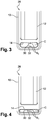
- a system for triggering an electrical signal is located inside an aqueous solution filter housing 10.
- the housing 10 consists of two half filter boxes 28, which are made by plastic injection systems or by metal material forming systems. The two parts correspond for one to the lower part 10B of the housing and for the other to the upper part of the housing 10A.
- the triggering system comprises a membrane 14 which is preferably located in the bottom of the housing 10B, below the filtering layer 12. The membrane 14 is deformable during the passage from the liquid phase to the solid phase of the aqueous solution.
- the membrane 14 is fixed and retained on its periphery by gluing, overmoulding, or by a clamping system which consists of closing the two boxes on the membrane 14 by various means of sealing assembly which are the following for plastics: the hot welding method, the three methods of vibration welding (ultrasonic welding, vibration welding or the combination of both ultrasonic and vibration methods).
- the membrane 14 comprises the first electrical contact 16A of the mechanical switch control system stuck on the membrane 14 facing the bottom of the lower housing 10B.
- the second electrical contact 16B of the mechanical switch control system is mounted opposite and glued into the bottom of the lower housing 10B, and oriented towards the upper part of the housing 16A.
- the invention describes a system for triggering an electrical signal during a phase change of the aqueous solution which has a switch control system 16 of the membrane electrical contact type.
- the triggering system of an electrical signal is located inside an aqueous solution filter housing 10.
- the triggering system comprises a membrane 14 which is preferably located in the bottom of the housing 10B, below the filtering layer 12.
- the membrane 14 consists of a closed envelope of round, spheroidal, rectangular shape with round or shaped edge of rugby ball.
- the membrane 14 is deformable during the phase change, from the liquid phase to the solid phase of the aqueous solution, and vice versa.
- the membrane 14 contains either a gas or a flexible foam.
- the membrane 14 When changing the gel of the liquid phase, its volume increases and pushes the membrane 14 below.
- the membrane 14 comprises two electrical contacts, located opposite each other, on either side of the membrane, the first contact up on the membrane and the second contact down on the membrane, which are either overmolded or glued on the membrane 14, inside the inner chamber (C) .
- the inner chamber (C) During the passage from the liquid phase to the solid phase of the aqueous solution, its volume increases and deforms the membrane 14 which makes touch the two contacts of the switch system 16, which closes the switch which itself triggers a S1 electrical signal to allow to start the heating system of the aqueous solution.
- the invention describes a device for triggering an electrical signal during a phase change, from the liquid phase to the solid phase of the aqueous solution, and vice versa.
- This device has a switch control system 16 of Reed contact type (magnetic switch placed in a protective glass ball).
- the device for triggering an electrical signal is located inside a box 10 of the filter.
- the triggering device comprises a membrane 14 which is preferably located in the bottom of the housing 10B, below the filtering layer 12.
- the membrane 14 is deformable during the passage of the liquid phase to the solid phase of the aqueous solution.
- the membrane 14 consists of a closed envelope of round, spheroidal, rectangular shape with a round edge or in the form of a rugby ball.
- the membrane 14 contains either a gas or a flexible foam.
- the membrane 14 comprises a magnet and a reed switch, located opposite each other with respect to the center of the volume which are either fixed by gluing or other fastening system.
- a magnet and a reed switch located opposite each other with respect to the center of the volume which are either fixed by gluing or other fastening system.
- its volume increases and deforms the membrane 14 which brings the magnet 26 of the Reed switch 24.
- the Reed switch 24 closes and triggers an electrical signal S1 to start the heating system of the aqueous solution.
- the logic of the switch can be reversed: the increase in the volume of the solid phase brings the magnet closer to the Reed switch which then opens; the reheating controller, electronic circuit type or electromechanical relay, then feeds the reheating.
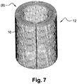
- a filter element 8 of the aqueous solution filter provided with a heating means 12, for example integrated in a filtering layer 10.
- a heating means 12 is totally integrated in the filtering layer 10.
- the filtering layer 10 is preferably composed of a cellulose-based media with carbon charges, the carbon being an electrical conductor.
- the carbon load can be replaced by conductive ink print tracks or any other electrically conductive element.
- the electrical conductor property of carbon charges and conductive ink print tracks or any other electrically conductive element allows heat to be released through these elements by the Joule effect.
- the filter layer may also be composed of a synthetic fabric-based media.
- a heating means device is fully described in the application filed today under the title "aqueous solution filter with heating means".
Landscapes
- Chemical & Material Sciences (AREA)
- Chemical Kinetics & Catalysis (AREA)
- Separation Using Semi-Permeable Membranes (AREA)
- Filtering Materials (AREA)
- Exhaust Gas After Treatment (AREA)
- Resistance Heating (AREA)
Claims (9)
- Filter mit wässriger Lösung (28), wie etwa Harnstoff, für eine Einrichtung zur selektiven katalytischen Reduktion von Dieselfahrzeugen, wobei der Filter ein Gehäuse enthält, das mit einem Einlass und einem Auslass versehen ist und in dessen Inneren ein Filterelement angeordnet ist, sowie mit einer Detektionsvorrichtung zum Erfassen von Volumenänderungen im Zusammenhang mit Phasenwechsel der wässrigen Lösung, wobei der Filter ferner mit Signalisierungsvorrichtungen (17) zum Signalisieren der Volumenänderungen der Phase der wässrigen Lösung versehen ist, dadurch gekennzeichnet, dass
die Signalisierungsmittel (17) einen Schalter (16) enthalten, der bei Phasenwechsel umschaltet. - Filter (28) nach Anspruch 1, wobei die Signalisierungsvorrichtungen (17) ferner eine verformbare Membran (14) enthalten, die mit dem Schalter zusammenwirkt, um einen Phasenwechsel zu signalisieren.
- Filter (28) nach Anspruch 2, wobei die Membran (14) eine Expansionskammer (C) für die Volumenänderungen definiert.
- Filter (28) nach dem vorangehenden Anspruch, wobei die Kammer (C) mit einem Gas oder einem weichen Schaum gefüllt ist.
- Filter (28) nach Anspruch 3, wobei die Membran flach ist.
- Filter (28) nach Anspruch 4, wobei der Schalter (16) sich in der Kammer (C) befindet.
- Filter (28) nach Anspruch 3, wobei der Schalter zumindest einen an der Membran (14) angeordneten Kontakt enthält.
- Filter (28) nach Anspruch 4, wobei der Schalter (24) über einen Magneten (26) aktiviert wird, wobei der Schalter als Reed-Schalter ausgeführt ist und wobei der Schalter bzw. der Magnet an der Membran angeordnet ist.
- Filter nach einem der vorangehenden Ansprüche, wobei der Filter eine dem Filterelement (10) integrierte Heizeinrichtung (12) enthält.
Applications Claiming Priority (2)
| Application Number | Priority Date | Filing Date | Title |
|---|---|---|---|
| FR1362510A FR3014704B1 (fr) | 2013-12-12 | 2013-12-12 | Dispositif de declenchement d’un signal electrique pour filtre a solution aqueuse |
| PCT/EP2014/076641 WO2015086440A1 (fr) | 2013-12-12 | 2014-12-04 | Dispositif de declenchement d'un signal electrique pour filtre a solution aqueuse |
Publications (2)
| Publication Number | Publication Date |
|---|---|
| EP3079790A1 EP3079790A1 (de) | 2016-10-19 |
| EP3079790B1 true EP3079790B1 (de) | 2018-02-21 |
Family
ID=50102075
Family Applications (1)
| Application Number | Title | Priority Date | Filing Date |
|---|---|---|---|
| EP14806328.2A Active EP3079790B1 (de) | 2013-12-12 | 2014-12-04 | Vorrichtung zum auslösen eines elektrischen signals für ein filter mit einer wässrigen lösung |
Country Status (5)
| Country | Link |
|---|---|
| US (1) | US10300413B2 (de) |
| EP (1) | EP3079790B1 (de) |
| CN (1) | CN105813709B (de) |
| FR (1) | FR3014704B1 (de) |
| WO (1) | WO2015086440A1 (de) |
Families Citing this family (3)
| Publication number | Priority date | Publication date | Assignee | Title |
|---|---|---|---|---|
| DE102015214167A1 (de) * | 2015-07-27 | 2017-02-02 | Robert Bosch Gmbh | Ausgleichselement für einen Flüssigkeitsfilter |
| DE102015010562A1 (de) * | 2015-08-12 | 2017-02-16 | Hydac Filtertechnik Gmbh | Filtervorrichtung nebst Filterelement |
| DE102015010533A1 (de) | 2015-08-12 | 2017-02-16 | Hydac Filtertechnik Gmbh | Filtervorrichtung nebst Filterelement |
Family Cites Families (6)
| Publication number | Priority date | Publication date | Assignee | Title |
|---|---|---|---|---|
| DE10161132A1 (de) * | 2001-12-12 | 2003-06-26 | Siemens Ag | Membranpumpe mit integriertem Drucksensor |
| FR2916188B1 (fr) | 2007-05-16 | 2011-05-06 | Inergy Automotive Systems Res | Reservoir a uree et embase avec element chauffant integre. |
| DE102008022991A1 (de) * | 2008-05-09 | 2009-11-12 | Emitec Gesellschaft Für Emissionstechnologie Mbh | Vorrichtung zur Förderung eines Reduktionsmittels und Verfahren zur Herstellung eines Kraftfahrzeuges |
| US9463399B2 (en) * | 2009-11-12 | 2016-10-11 | Donaldson Company, Inc. | Liquid filter construction for freezing environments |
| DE102010027069B3 (de) * | 2010-07-13 | 2012-02-23 | Mann + Hummel Gmbh | Harnstoff-Wasser-Lösung-Filtersystem |
| DE102012010981A1 (de) * | 2012-06-02 | 2013-12-05 | Hydac Filtertechnik Gmbh | System zur Abgasnachbehandlung bei Verbrennungsmotoren |
-
2013
- 2013-12-12 FR FR1362510A patent/FR3014704B1/fr not_active Expired - Fee Related
-
2014
- 2014-12-04 CN CN201480067653.XA patent/CN105813709B/zh active Active
- 2014-12-04 US US15/102,913 patent/US10300413B2/en active Active
- 2014-12-04 EP EP14806328.2A patent/EP3079790B1/de active Active
- 2014-12-04 WO PCT/EP2014/076641 patent/WO2015086440A1/fr not_active Ceased
Also Published As
| Publication number | Publication date |
|---|---|
| CN105813709B (zh) | 2017-09-08 |
| WO2015086440A1 (fr) | 2015-06-18 |
| CN105813709A (zh) | 2016-07-27 |
| EP3079790A1 (de) | 2016-10-19 |
| US10300413B2 (en) | 2019-05-28 |
| FR3014704A1 (fr) | 2015-06-19 |
| US20160325210A1 (en) | 2016-11-10 |
| FR3014704B1 (fr) | 2017-04-28 |
Similar Documents
| Publication | Publication Date | Title |
|---|---|---|
| WO2011114045A1 (fr) | Interrupteur electrique a actionnement pyrotechnique | |
| WO2015086440A1 (fr) | Dispositif de declenchement d'un signal electrique pour filtre a solution aqueuse | |
| US10906390B2 (en) | Tank component, in particular for exhaust-gas treatment system of internal-combustion engines | |
| EP3137744A1 (de) | Diagnosevorrichtung für ein partikelfilter | |
| FR2918576A1 (fr) | Systeme d'alimentation d'un liquide pour vehicule et module pompe/filtre integre. | |
| JP2013504706A (ja) | 還元剤の供給装置 | |
| FR2899683A1 (fr) | Capteur de temperature et procede de fabrication de celui-ci | |
| WO2020099392A1 (fr) | Tuyau extincteur pour un compartiment batterie ou un véhicule à moteur | |
| EP1964740A1 (de) | Neuartige funktionelle Architektur eines Vakuumkreislaufs in einem Kraftfahrzeug zur Erhaltung der Integrität der pneumatischen Stellglieder oder Aufnehmer | |
| FR3080653A1 (fr) | Dispositif de chauffage bi-energie pour reservoir de produits aqueux | |
| EP0863398B1 (de) | Vorrichtung zum Nachweis der Verschmutzung einer isolierenden Umgebung, und zur lokalen Heizung dergleichen | |
| FR3078501A1 (fr) | Procede de fabrication d'un element d'une piece de carrosserie comportant un systeme de degivrage | |
| CN203939562U (zh) | 发动机排气系统和机动车辆 | |
| FR3014705A1 (fr) | Filtre a solution aqueuse avec moyen de chauffage | |
| EP4065401B1 (de) | Mehrlippendichtung und dichtvorrichtung mit einer solchen dichtung | |
| FR2923069A1 (fr) | Ecran de protection acoustique comprenant une coque poreuse | |
| FR2596811A1 (fr) | Procede et dispositif de defigeage des carburants | |
| JPS5994365A (ja) | 鉛蓄電池用電槽カバ− | |
| EP2085583B1 (de) | Diagnosevorrichtung und -verfahren eines Partikelfilters für einen Verbrennungsmotor and einen dazu gehörenden Drucksensor | |
| FR2944830A3 (fr) | Dispositif de detection de la separation mecanique de deux pieces d'un moteur de vehicule automobile assemblees l'une a l'autre et moteur comportant un tel dispositif | |
| FR2898656A1 (fr) | Clapet de surpression pour gaz de carter | |
| EP1987241A1 (de) | Verfahren und vorrichtung für einspritzabsteuerung in einer abgasstrecke | |
| WO2008078021A2 (fr) | Media filtrant pour dispositif de filtration des gaz d'echappement d'un moteur diesel, dispositif de filtration mettant en oeuvre un tel media, et ligne d'echappement des gaz d'un moteur a combustion interne mettant en oeuvre un tel dispositif | |
| FR2963105A1 (fr) | Dispositif de detection de polluants dans un milieu fluide, notamment d'hydrocarbures ou de composes organiques dans un milieu aqueux | |
| FR2913069A3 (fr) | Dispositif d'injection avec protection thermique du nez d'injecteur |
Legal Events
| Date | Code | Title | Description |
|---|---|---|---|
| PUAI | Public reference made under article 153(3) epc to a published international application that has entered the european phase |
Free format text: ORIGINAL CODE: 0009012 |
|
| 17P | Request for examination filed |
Effective date: 20160712 |
|
| AK | Designated contracting states |
Kind code of ref document: A1 Designated state(s): AL AT BE BG CH CY CZ DE DK EE ES FI FR GB GR HR HU IE IS IT LI LT LU LV MC MK MT NL NO PL PT RO RS SE SI SK SM TR |
|
| AX | Request for extension of the european patent |
Extension state: BA ME |
|
| DAX | Request for extension of the european patent (deleted) | ||
| GRAP | Despatch of communication of intention to grant a patent |
Free format text: ORIGINAL CODE: EPIDOSNIGR1 |
|
| INTG | Intention to grant announced |
Effective date: 20170811 |
|
| GRAS | Grant fee paid |
Free format text: ORIGINAL CODE: EPIDOSNIGR3 |
|
| GRAA | (expected) grant |
Free format text: ORIGINAL CODE: 0009210 |
|
| AK | Designated contracting states |
Kind code of ref document: B1 Designated state(s): AL AT BE BG CH CY CZ DE DK EE ES FI FR GB GR HR HU IE IS IT LI LT LU LV MC MK MT NL NO PL PT RO RS SE SI SK SM TR |
|
| REG | Reference to a national code |
Ref country code: GB Ref legal event code: FG4D Free format text: NOT ENGLISH |
|
| REG | Reference to a national code |
Ref country code: CH Ref legal event code: EP |
|
| REG | Reference to a national code |
Ref country code: AT Ref legal event code: REF Ref document number: 971092 Country of ref document: AT Kind code of ref document: T Effective date: 20180315 |
|
| REG | Reference to a national code |
Ref country code: IE Ref legal event code: FG4D Free format text: LANGUAGE OF EP DOCUMENT: FRENCH |
|
| REG | Reference to a national code |
Ref country code: DE Ref legal event code: R096 Ref document number: 602014021371 Country of ref document: DE |
|
| REG | Reference to a national code |
Ref country code: NL Ref legal event code: MP Effective date: 20180221 |
|
| REG | Reference to a national code |
Ref country code: LT Ref legal event code: MG4D |
|
| REG | Reference to a national code |
Ref country code: AT Ref legal event code: MK05 Ref document number: 971092 Country of ref document: AT Kind code of ref document: T Effective date: 20180221 |
|
| PG25 | Lapsed in a contracting state [announced via postgrant information from national office to epo] |
Ref country code: FI Free format text: LAPSE BECAUSE OF FAILURE TO SUBMIT A TRANSLATION OF THE DESCRIPTION OR TO PAY THE FEE WITHIN THE PRESCRIBED TIME-LIMIT Effective date: 20180221 Ref country code: NO Free format text: LAPSE BECAUSE OF FAILURE TO SUBMIT A TRANSLATION OF THE DESCRIPTION OR TO PAY THE FEE WITHIN THE PRESCRIBED TIME-LIMIT Effective date: 20180521 Ref country code: HR Free format text: LAPSE BECAUSE OF FAILURE TO SUBMIT A TRANSLATION OF THE DESCRIPTION OR TO PAY THE FEE WITHIN THE PRESCRIBED TIME-LIMIT Effective date: 20180221 Ref country code: NL Free format text: LAPSE BECAUSE OF FAILURE TO SUBMIT A TRANSLATION OF THE DESCRIPTION OR TO PAY THE FEE WITHIN THE PRESCRIBED TIME-LIMIT Effective date: 20180221 Ref country code: LT Free format text: LAPSE BECAUSE OF FAILURE TO SUBMIT A TRANSLATION OF THE DESCRIPTION OR TO PAY THE FEE WITHIN THE PRESCRIBED TIME-LIMIT Effective date: 20180221 Ref country code: ES Free format text: LAPSE BECAUSE OF FAILURE TO SUBMIT A TRANSLATION OF THE DESCRIPTION OR TO PAY THE FEE WITHIN THE PRESCRIBED TIME-LIMIT Effective date: 20180221 Ref country code: CY Free format text: LAPSE BECAUSE OF FAILURE TO SUBMIT A TRANSLATION OF THE DESCRIPTION OR TO PAY THE FEE WITHIN THE PRESCRIBED TIME-LIMIT Effective date: 20180221 |
|
| PG25 | Lapsed in a contracting state [announced via postgrant information from national office to epo] |
Ref country code: BG Free format text: LAPSE BECAUSE OF FAILURE TO SUBMIT A TRANSLATION OF THE DESCRIPTION OR TO PAY THE FEE WITHIN THE PRESCRIBED TIME-LIMIT Effective date: 20180521 Ref country code: GR Free format text: LAPSE BECAUSE OF FAILURE TO SUBMIT A TRANSLATION OF THE DESCRIPTION OR TO PAY THE FEE WITHIN THE PRESCRIBED TIME-LIMIT Effective date: 20180522 Ref country code: LV Free format text: LAPSE BECAUSE OF FAILURE TO SUBMIT A TRANSLATION OF THE DESCRIPTION OR TO PAY THE FEE WITHIN THE PRESCRIBED TIME-LIMIT Effective date: 20180221 Ref country code: SE Free format text: LAPSE BECAUSE OF FAILURE TO SUBMIT A TRANSLATION OF THE DESCRIPTION OR TO PAY THE FEE WITHIN THE PRESCRIBED TIME-LIMIT Effective date: 20180221 Ref country code: AT Free format text: LAPSE BECAUSE OF FAILURE TO SUBMIT A TRANSLATION OF THE DESCRIPTION OR TO PAY THE FEE WITHIN THE PRESCRIBED TIME-LIMIT Effective date: 20180221 Ref country code: RS Free format text: LAPSE BECAUSE OF FAILURE TO SUBMIT A TRANSLATION OF THE DESCRIPTION OR TO PAY THE FEE WITHIN THE PRESCRIBED TIME-LIMIT Effective date: 20180221 |
|
| PG25 | Lapsed in a contracting state [announced via postgrant information from national office to epo] |
Ref country code: MT Free format text: LAPSE BECAUSE OF FAILURE TO SUBMIT A TRANSLATION OF THE DESCRIPTION OR TO PAY THE FEE WITHIN THE PRESCRIBED TIME-LIMIT Effective date: 20180221 |
|
| PG25 | Lapsed in a contracting state [announced via postgrant information from national office to epo] |
Ref country code: PL Free format text: LAPSE BECAUSE OF FAILURE TO SUBMIT A TRANSLATION OF THE DESCRIPTION OR TO PAY THE FEE WITHIN THE PRESCRIBED TIME-LIMIT Effective date: 20180221 Ref country code: EE Free format text: LAPSE BECAUSE OF FAILURE TO SUBMIT A TRANSLATION OF THE DESCRIPTION OR TO PAY THE FEE WITHIN THE PRESCRIBED TIME-LIMIT Effective date: 20180221 Ref country code: IT Free format text: LAPSE BECAUSE OF FAILURE TO SUBMIT A TRANSLATION OF THE DESCRIPTION OR TO PAY THE FEE WITHIN THE PRESCRIBED TIME-LIMIT Effective date: 20180221 Ref country code: AL Free format text: LAPSE BECAUSE OF FAILURE TO SUBMIT A TRANSLATION OF THE DESCRIPTION OR TO PAY THE FEE WITHIN THE PRESCRIBED TIME-LIMIT Effective date: 20180221 |
|
| REG | Reference to a national code |
Ref country code: DE Ref legal event code: R097 Ref document number: 602014021371 Country of ref document: DE |
|
| PG25 | Lapsed in a contracting state [announced via postgrant information from national office to epo] |
Ref country code: CZ Free format text: LAPSE BECAUSE OF FAILURE TO SUBMIT A TRANSLATION OF THE DESCRIPTION OR TO PAY THE FEE WITHIN THE PRESCRIBED TIME-LIMIT Effective date: 20180221 Ref country code: SM Free format text: LAPSE BECAUSE OF FAILURE TO SUBMIT A TRANSLATION OF THE DESCRIPTION OR TO PAY THE FEE WITHIN THE PRESCRIBED TIME-LIMIT Effective date: 20180221 Ref country code: SK Free format text: LAPSE BECAUSE OF FAILURE TO SUBMIT A TRANSLATION OF THE DESCRIPTION OR TO PAY THE FEE WITHIN THE PRESCRIBED TIME-LIMIT Effective date: 20180221 Ref country code: DK Free format text: LAPSE BECAUSE OF FAILURE TO SUBMIT A TRANSLATION OF THE DESCRIPTION OR TO PAY THE FEE WITHIN THE PRESCRIBED TIME-LIMIT Effective date: 20180221 |
|
| PLBE | No opposition filed within time limit |
Free format text: ORIGINAL CODE: 0009261 |
|
| STAA | Information on the status of an ep patent application or granted ep patent |
Free format text: STATUS: NO OPPOSITION FILED WITHIN TIME LIMIT |
|
| 26N | No opposition filed |
Effective date: 20181122 |
|
| REG | Reference to a national code |
Ref country code: DE Ref legal event code: R081 Ref document number: 602014021371 Country of ref document: DE Owner name: DELPHI TECHNOLOGIES IP LIMITED, BB Free format text: FORMER OWNER: DELPHI INTERNATIONAL OPERATIONS LUXEMBOURG S.A R.L., 4940 BASCHARAGE, LU Ref country code: DE Ref legal event code: R081 Ref document number: 602014021371 Country of ref document: DE Owner name: DELPHI TECHNOLOGIES IP LIMITED, BB Free format text: FORMER OWNER: DELPHI INTERNATIONAL OPERATIONS LUXEMBOURG S.A R.L., 4940 HAUTCHARAGE, LU |
|
| PG25 | Lapsed in a contracting state [announced via postgrant information from national office to epo] |
Ref country code: SI Free format text: LAPSE BECAUSE OF FAILURE TO SUBMIT A TRANSLATION OF THE DESCRIPTION OR TO PAY THE FEE WITHIN THE PRESCRIBED TIME-LIMIT Effective date: 20180221 |
|
| REG | Reference to a national code |
Ref country code: GB Ref legal event code: 732E Free format text: REGISTERED BETWEEN 20190222 AND 20190227 |
|
| REG | Reference to a national code |
Ref country code: CH Ref legal event code: PL |
|
| PG25 | Lapsed in a contracting state [announced via postgrant information from national office to epo] |
Ref country code: MC Free format text: LAPSE BECAUSE OF FAILURE TO SUBMIT A TRANSLATION OF THE DESCRIPTION OR TO PAY THE FEE WITHIN THE PRESCRIBED TIME-LIMIT Effective date: 20180221 Ref country code: LU Free format text: LAPSE BECAUSE OF NON-PAYMENT OF DUE FEES Effective date: 20181204 |
|
| REG | Reference to a national code |
Ref country code: IE Ref legal event code: MM4A |
|
| REG | Reference to a national code |
Ref country code: BE Ref legal event code: MM Effective date: 20181231 |
|
| PG25 | Lapsed in a contracting state [announced via postgrant information from national office to epo] |
Ref country code: IE Free format text: LAPSE BECAUSE OF NON-PAYMENT OF DUE FEES Effective date: 20181204 |
|
| PG25 | Lapsed in a contracting state [announced via postgrant information from national office to epo] |
Ref country code: BE Free format text: LAPSE BECAUSE OF NON-PAYMENT OF DUE FEES Effective date: 20181231 |
|
| PG25 | Lapsed in a contracting state [announced via postgrant information from national office to epo] |
Ref country code: LI Free format text: LAPSE BECAUSE OF NON-PAYMENT OF DUE FEES Effective date: 20181231 Ref country code: CH Free format text: LAPSE BECAUSE OF NON-PAYMENT OF DUE FEES Effective date: 20181231 |
|
| PG25 | Lapsed in a contracting state [announced via postgrant information from national office to epo] |
Ref country code: TR Free format text: LAPSE BECAUSE OF FAILURE TO SUBMIT A TRANSLATION OF THE DESCRIPTION OR TO PAY THE FEE WITHIN THE PRESCRIBED TIME-LIMIT Effective date: 20180221 |
|
| PG25 | Lapsed in a contracting state [announced via postgrant information from national office to epo] |
Ref country code: PT Free format text: LAPSE BECAUSE OF FAILURE TO SUBMIT A TRANSLATION OF THE DESCRIPTION OR TO PAY THE FEE WITHIN THE PRESCRIBED TIME-LIMIT Effective date: 20180221 |
|
| PG25 | Lapsed in a contracting state [announced via postgrant information from national office to epo] |
Ref country code: RO Free format text: LAPSE BECAUSE OF FAILURE TO SUBMIT A TRANSLATION OF THE DESCRIPTION OR TO PAY THE FEE WITHIN THE PRESCRIBED TIME-LIMIT Effective date: 20180221 Ref country code: MK Free format text: LAPSE BECAUSE OF NON-PAYMENT OF DUE FEES Effective date: 20180221 Ref country code: HU Free format text: LAPSE BECAUSE OF FAILURE TO SUBMIT A TRANSLATION OF THE DESCRIPTION OR TO PAY THE FEE WITHIN THE PRESCRIBED TIME-LIMIT; INVALID AB INITIO Effective date: 20141204 |
|
| PG25 | Lapsed in a contracting state [announced via postgrant information from national office to epo] |
Ref country code: IS Free format text: LAPSE BECAUSE OF FAILURE TO SUBMIT A TRANSLATION OF THE DESCRIPTION OR TO PAY THE FEE WITHIN THE PRESCRIBED TIME-LIMIT Effective date: 20180621 |
|
| PGFP | Annual fee paid to national office [announced via postgrant information from national office to epo] |
Ref country code: GB Payment date: 20201228 Year of fee payment: 7 Ref country code: FR Payment date: 20201227 Year of fee payment: 7 |
|
| GBPC | Gb: european patent ceased through non-payment of renewal fee |
Effective date: 20211204 |
|
| PG25 | Lapsed in a contracting state [announced via postgrant information from national office to epo] |
Ref country code: GB Free format text: LAPSE BECAUSE OF NON-PAYMENT OF DUE FEES Effective date: 20211204 |
|
| PG25 | Lapsed in a contracting state [announced via postgrant information from national office to epo] |
Ref country code: FR Free format text: LAPSE BECAUSE OF NON-PAYMENT OF DUE FEES Effective date: 20211231 |
|
| P01 | Opt-out of the competence of the unified patent court (upc) registered |
Effective date: 20230327 |
|
| REG | Reference to a national code |
Ref country code: DE Ref legal event code: R081 Ref document number: 602014021371 Country of ref document: DE Owner name: PHINIA DELPHI LUXEMBOURG SARL, LU Free format text: FORMER OWNER: DELPHI TECHNOLOGIES IP LIMITED, ST. MICHAEL, BB |
|
| PGFP | Annual fee paid to national office [announced via postgrant information from national office to epo] |
Ref country code: DE Payment date: 20251118 Year of fee payment: 12 |