EP3079578B1 - Verwendung von ergänzungsinformationen zur verbesserung der inverser problemlösungen - Google Patents
Verwendung von ergänzungsinformationen zur verbesserung der inverser problemlösungen Download PDFInfo
- Publication number
- EP3079578B1 EP3079578B1 EP14870144.4A EP14870144A EP3079578B1 EP 3079578 B1 EP3079578 B1 EP 3079578B1 EP 14870144 A EP14870144 A EP 14870144A EP 3079578 B1 EP3079578 B1 EP 3079578B1
- Authority
- EP
- European Patent Office
- Prior art keywords
- boundary condition
- patient
- electrical activity
- data
- location
- Prior art date
- Legal status (The legal status is an assumption and is not a legal conclusion. Google has not performed a legal analysis and makes no representation as to the accuracy of the status listed.)
- Active
Links
- 230000000153 supplemental effect Effects 0.000 title claims description 54
- 230000000694 effects Effects 0.000 claims description 79
- 238000000034 method Methods 0.000 claims description 76
- 238000005259 measurement Methods 0.000 claims description 43
- 230000000747 cardiac effect Effects 0.000 claims description 31
- 238000003384 imaging method Methods 0.000 claims description 29
- 230000003902 lesion Effects 0.000 claims description 24
- 231100000241 scar Toxicity 0.000 claims description 24
- 230000004044 response Effects 0.000 claims description 13
- 210000003484 anatomy Anatomy 0.000 claims description 11
- 239000000523 sample Substances 0.000 claims description 11
- 238000004441 surface measurement Methods 0.000 claims description 6
- 231100001012 cardiac lesion Toxicity 0.000 claims 1
- 229940030602 cardiac therapy drug Drugs 0.000 claims 1
- 238000002560 therapeutic procedure Methods 0.000 description 37
- 239000011159 matrix material Substances 0.000 description 20
- 230000004807 localization Effects 0.000 description 14
- 230000009466 transformation Effects 0.000 description 9
- 238000013507 mapping Methods 0.000 description 8
- 238000012545 processing Methods 0.000 description 8
- 210000001519 tissue Anatomy 0.000 description 7
- 238000002679 ablation Methods 0.000 description 6
- 230000008569 process Effects 0.000 description 6
- 208000032544 Cicatrix Diseases 0.000 description 5
- 238000013459 approach Methods 0.000 description 5
- 239000000306 component Substances 0.000 description 5
- 230000006870 function Effects 0.000 description 5
- 230000037387 scars Effects 0.000 description 5
- 238000003860 storage Methods 0.000 description 5
- 238000004590 computer program Methods 0.000 description 4
- 238000002001 electrophysiology Methods 0.000 description 4
- 230000007831 electrophysiology Effects 0.000 description 4
- 238000012544 monitoring process Methods 0.000 description 4
- 238000002591 computed tomography Methods 0.000 description 3
- 210000005003 heart tissue Anatomy 0.000 description 3
- 230000000638 stimulation Effects 0.000 description 3
- 238000002604 ultrasonography Methods 0.000 description 3
- 238000012800 visualization Methods 0.000 description 3
- 238000009795 derivation Methods 0.000 description 2
- 238000010586 diagram Methods 0.000 description 2
- 238000009826 distribution Methods 0.000 description 2
- 238000005516 engineering process Methods 0.000 description 2
- 238000000605 extraction Methods 0.000 description 2
- 238000009472 formulation Methods 0.000 description 2
- 239000000203 mixture Substances 0.000 description 2
- 230000011218 segmentation Effects 0.000 description 2
- 230000003068 static effect Effects 0.000 description 2
- 238000012546 transfer Methods 0.000 description 2
- 238000010317 ablation therapy Methods 0.000 description 1
- 230000004075 alteration Effects 0.000 description 1
- 230000003190 augmentative effect Effects 0.000 description 1
- 230000008901 benefit Effects 0.000 description 1
- 238000004364 calculation method Methods 0.000 description 1
- 210000005242 cardiac chamber Anatomy 0.000 description 1
- 238000013153 catheter ablation Methods 0.000 description 1
- 210000000038 chest Anatomy 0.000 description 1
- 238000010276 construction Methods 0.000 description 1
- 238000010924 continuous production Methods 0.000 description 1
- 239000008358 core component Substances 0.000 description 1
- 230000001419 dependent effect Effects 0.000 description 1
- 238000002405 diagnostic procedure Methods 0.000 description 1
- 238000002565 electrocardiography Methods 0.000 description 1
- 238000011156 evaluation Methods 0.000 description 1
- 238000001914 filtration Methods 0.000 description 1
- 238000002594 fluoroscopy Methods 0.000 description 1
- 230000006872 improvement Effects 0.000 description 1
- 230000003993 interaction Effects 0.000 description 1
- 238000003874 inverse correlation nuclear magnetic resonance spectroscopy Methods 0.000 description 1
- 238000002595 magnetic resonance imaging Methods 0.000 description 1
- 238000004519 manufacturing process Methods 0.000 description 1
- 238000013178 mathematical model Methods 0.000 description 1
- 238000012986 modification Methods 0.000 description 1
- 230000004048 modification Effects 0.000 description 1
- 210000004165 myocardium Anatomy 0.000 description 1
- 230000003287 optical effect Effects 0.000 description 1
- 210000000056 organ Anatomy 0.000 description 1
- 238000007674 radiofrequency ablation Methods 0.000 description 1
- 238000011160 research Methods 0.000 description 1
- 230000004936 stimulating effect Effects 0.000 description 1
- 239000000126 substance Substances 0.000 description 1
- 230000001360 synchronised effect Effects 0.000 description 1
- 230000002123 temporal effect Effects 0.000 description 1
Images


Classifications
-
- A—HUMAN NECESSITIES
- A61—MEDICAL OR VETERINARY SCIENCE; HYGIENE
- A61B—DIAGNOSIS; SURGERY; IDENTIFICATION
- A61B5/00—Measuring for diagnostic purposes; Identification of persons
- A61B5/72—Signal processing specially adapted for physiological signals or for diagnostic purposes
- A61B5/7271—Specific aspects of physiological measurement analysis
- A61B5/7278—Artificial waveform generation or derivation, e.g. synthesising signals from measured signals
-
- A—HUMAN NECESSITIES
- A61—MEDICAL OR VETERINARY SCIENCE; HYGIENE
- A61B—DIAGNOSIS; SURGERY; IDENTIFICATION
- A61B5/00—Measuring for diagnostic purposes; Identification of persons
- A61B5/24—Detecting, measuring or recording bioelectric or biomagnetic signals of the body or parts thereof
- A61B5/316—Modalities, i.e. specific diagnostic methods
- A61B5/318—Heart-related electrical modalities, e.g. electrocardiography [ECG]
- A61B5/327—Generation of artificial ECG signals based on measured signals, e.g. to compensate for missing leads
-
- A—HUMAN NECESSITIES
- A61—MEDICAL OR VETERINARY SCIENCE; HYGIENE
- A61B—DIAGNOSIS; SURGERY; IDENTIFICATION
- A61B18/00—Surgical instruments, devices or methods for transferring non-mechanical forms of energy to or from the body
- A61B2018/00571—Surgical instruments, devices or methods for transferring non-mechanical forms of energy to or from the body for achieving a particular surgical effect
- A61B2018/00577—Ablation
Definitions
- This disclosure relates to solving the inverse problem by employing supplemental information.
- the inverse problem can be solved to reconstruct electrical activity inside a body surface based measured electrical activity on the body surface.
- One example of such an application relates to electrocardiographic imaging where electrical potentials measured on a torso can be combined with geometry information to reconstruct electrical potentials on a cardiac surface.
- a computer can combine and process the body surface electrical potentials activity data and the geometry data to reconstruct estimates of the cardiac surface potentials (e.g., epicardial potentials).
- the reconstructed cardiac surface potentials may in turn be processed to generate appropriate epicardial cardiac surface potential maps, epicardial cardiac surface electrograms, and epicardial cardiac surface isochrones.
- WO 2014/118535 A2 relates to a computerized system based on non-expandable catheters and electropotential guidance for fast cardiac mapping and ablation.
- the core components that together make up the architecture of the system are: 1) a catheter or a set of catheters that are multi-polar and non-expandable, at least one of them is steerable and suitable for catheter ablation, all of them allow contact and/or non-contact sensing of potentials from the heart muscle, 2) a multi-channel amplifier and a signal processor, 3) a computer with software and storage and optional hardware accelerator(s), 4) a pacing/driving/tracking generator, and 5) body surface electrodes.
- US 2009/275827 A1 refers to a system for assessing proximity between an electrode and tissue.
- Document US 2002/128565 A1 discloses a system and method for non-invasively determining electrical activity of the heart of a human being. Electrical potentials are measured on the body surface via an electrode vest, and a body surface potential map is generated. A matrix of transformation based on the geometry of the torso, the heart, locations of electrodes, and position of the heart within the torso is also determined with the aid of a processor, and a geometry determining device. The electrical potential distribution over the epicardial surface of the heart is then determined based ona regularized matrix of transformation, and the body surface potential map. Using the epicardial potential distributions, epicardial electrogram, isochronal are also reconstructed, and displayed via an output device.
- This disclosure relates to using supplemental information to improve inverse problem solutions, such as for electrophysiology.
- a method may include storing electrical measurement data and geometry.
- One or more boundary conditions can be determined based on supplemental information associated with at least one selected location associated with an anatomic envelope within a patient's body.
- Reconstructed electrical activity can be computed for a plurality of locations residing on the anatomic envelope within the patient's body based on the electrical data and the geometry data, the least one boundary condition being imposed to improve the computing.
- a system may include a boundary condition generator programmed to determine one or more boundary conditions based on supplemental information.
- a reconstruction engine can compute an estimate of electrical activity distributed on an anatomic envelope within a patient's body based on electrical data representing electrical activity acquired non-invasively from locations on a patient's body and geometry data representing the locations on a patient's body and spatial geometry of patient including the anatomic envelope within the patient's body.
- the one or more boundary conditions may be applied to constrain the computations to provide the estimate of electrical activity.
- An output generator may provide output data based on the computed estimate of electrical activity.
- the supplemental information includes information related to a location of a scar/lesion from at least one of an imaging modality, a direct vision, or a physical probe.
- the supplemental information can be utilized to constrain computations for reconstructing electrical activity on an anatomic envelope within a patient's body.
- the anatomic envelope can correspond to a surface of anatomical structure within the patient's body or to a virtual surface that is within the patient's body.
- the supplemental information relates to characteristics of the anatomic envelope of interest where electrical information was calculated from non-invasive electrical data.
- the supplemental information can be employed to determine a boundary condition that remains fixed over time.
- a fixed boundary condition can be represented as a preset low value for a voltage potential at one or more locations associated with the anatomic envelope of interest.
- Scar tissue or a lesion at a known anatomic location is an example of supplemental information that provides a fixed boundary condition (e.g., as can be determined from imaging data using one or more imaging modality).
- the supplemental information can be employed to determine a boundary condition that varies with respect to time.
- a variable boundary condition can be represented as time-varying voltage potential that is measured (e.g., via one or more contact or non-contact electrodes) at one or more locations associated with the anatomic envelope of interest. The location can also be fixed or it can vary over time.
- a catheter or probe can be inserted within the patient's body to apply and/or measure a signal at known location, which application or measurement may be employed as supplemental information to provide a corresponding variable boundary condition.
- purposes of the electrocardiography inverse problem include characterizing and/or localizing cardiac electrical activity and events from noninvasively measured electrical activity on the body surface, combined with geometry information for body surface where the measurements are made and a cardiac envelope of interest.
- cardiac envelope can correspond to an epicardial surface of a patient's heart, an epicardial surface of model heart (the patient's or a generic heart) or to any surface boundary within the patient's body have a known spatial relationship with respect to the patient's heart or a model heart.
- ECGI electrocardiographic imaging
- supplemental information can be utilized to provide valid boundary conditions to constrain the inverse problem.
- Each unit of supplemental information can be obtained before acquiring the potential and/or current information on the body surface, after acquiring the potential and/or current information and/or concurrently with acquisition of the potential and/or current information.
- the supplemental information can be employed to define one or more boundary conditions.
- FIG. 2 depicts an example of a system 10 to reconstruct electrical activity on an envelope using one or more boundary conditions determined from supplemental information.
- the system includes a mapping system 12 programmed to reconstruct an estimate of electrical activity for a region of interest and to generate map data 14 for display and/or further processing based on reconstructed estimate of electrical activity.
- the mapping system 12 includes a reconstruction engine 16 programmed to compute the estimate of electrical activity for the region of interest based on electrical data 18, geometry data 20 by performing an inverse method that is constrained by supplemental information 22.
- Examples of the supplemental information 22 can include intracardiac measurements of electrical activity (e.g., unipolar and/or dipole measurements), locations of scars or other lesions and/or user specified information associated with the cardiac envelope of interest for which the electrical activity estimates are reconstructed (e.g., by reconstruction engine 16). Additionally, a user can specify a condition for a prescribed location or region based on other a priori information.
- electrical activity e.g., unipolar and/or dipole measurements
- locations of scars or other lesions e.g., user specified information associated with the cardiac envelope of interest for which the electrical activity estimates are reconstructed (e.g., by reconstruction engine 16).
- a user can specify a condition for a prescribed location or region based on other a priori information.
- the mapping system 12 can also include a boundary condition generator 24 programmed to determine one or more boundary conditions 26 based on the supplemental information 22.
- each boundary condition 26 can correspond to a vector parameter having a parameter value (e.g., voltage potential) and an associated location.
- the boundary condition may also include a time parameter, such as if the boundary condition (e.g., location and/or voltage) varies over time.
- the location of a given boundary condition 26 can be a location in three-dimensional space corresponding to the anatomic region of interest (e.g., a cardiac envelope, such as an epicardial surface, endocardial surface or both).
- the boundary condition generator 24 can determine the boundary condition 26 to correspond to an intracardiac voltage potential measured for a given location on an epicardial or endocardial surface of the patient's heart.
- the location which may be fixed or vary over time, can be determined from a localization method (e.g., localization engine 188 of FIG. 6 ) and/or it may be specified in response to a user input (e.g., selecting a location on graphical user interface showing patient anatomy).
- the intracardiac electrical information may be from intracardiac measurements, such as from an electrophysiological study or from an intracardiac device (e.g., pacemaker, catheter or defibrillator), which may be permanently implanted or be positioned temporarily during an electrophysiology study.
- Intracardiac supplemental information may also be determined from invasive or non-invasive imaging modalities, for example.
- the boundary condition 26 can determine the boundary condition 26 to correspond to the location of scar tissue, a lesion or other anatomical structure that can limit or otherwise influence the propagation of electrical activity through the anatomy in a definable manner.
- the boundary condition 26 will remain fixed.
- scar tissue or other lesions which may be naturally occurring or be created (e.g., during treatment), tend to be electrically insulating and thus do not conduct electrical current.
- the parameter value for each boundary condition determined for scar/lesion regions on the anatomical envelope of interest can be set to a fixed low voltage or zero voltage.
- the locations on the region of interest for a given scar/lesion can be determined automatically, manually or semi-automatically (e.g., identified and then confirmed in response to a user input) from an invasive or non-invasive techniques, such as via an imaging modality, direct vision and/or physical probe.
- the inverse method 28 thus can be programmed compute estimates of reconstructed electrical activity on the anatomical envelope of interest based on non-invasive electrical data 18 and the geometry data.
- the computations implemented by the inverse method 28 can be constrained by imposing the one or more boundary conditions 26 to improve the computations.
- the inverse method 28 can be implemented according to any of a variety of known or yet to be developed inverse method. Examples of inverse algorithms that can be implemented as the inverse method 28 in the system 10 to reconstruct electrical activity on an envelope of interest constrained by supplemental information 22, as disclosed herein, include but are not limited to those disclosed in U.S. Patent Nos. 7,983,743 and 6,772,004 or U.S. Patent Publication No. 2011/0190649 .
- the mapping system 12 can also include a map generator programmed to generate map data based on the reconstructed electrical activity.
- the map generator can process the reconstructed electrical activity (e.g., electrical potentials) to generate map data 14 representing potential maps, electrograms, and isochrones as well as other derivations thereof.
- FIGS. 3 and 4 demonstrate examples of systems that can be utilized to reconstruct electrical potentials on a cardiac envelope using one or more boundary conditions determined from supplemental information.
- FIG. 3 is described in the context of using the boundary element method and
- FIG. 4 is described in the context of a meshless approach, namely using the method of fundamental solution. It will be understood that the use of boundary conditions, as disclosed herein, are applicable to other techniques for solving the inverse problem.
- FIG. 3 depicts an example of a system 50 to reconstruct electrograms employing boundary element method as part of the inverse solution.
- the system 50 includes reconstruction engine 52, such as can correspond to the reconstruction engine 16 of FIG. 1 .
- the reconstruction engine 52 can generate reconstructed electrical activity data 54 by combining geometry data 56 and non-invasively measured electrical data 58.
- the reconstruction engine 52 can implement an inverse method that is programmed to include a transformation matrix calculator 62 and regularization component 64.
- the reconstruction engine 52 further is configured to impose boundary condition data 60 on the computations implemented by the transformation matrix calculator 62.
- the values for each unit of the boundary condition being imposed can include fixed or variable boundary condition parameters.
- the boundary condition data 60 may be employed (e.g., by boundary condition generator 24) to produce an extended linear system that is constrained by each one or more boundary conditions that is applied.
- the transformation matrix calculator 62 can be programmed to compute an extended linear system in which the boundary condition data has been imposed, such as the following: where:
- the transformation matrix calculator 62 can be programmed to compute an extended linear system in which each such boundary condition data has been imposed, such as the following formulation:
- the boundary condition sets the voltage potential at the known locations defined by the boundary condition to zero (e.g., 0 V), as mentioned other fixed low voltage values could be used in other examples.
- the boundary conditions for locations corresponding to the identified scar/lesion region in Eq. 5 and/or the measured intracardiac locations of Eq. 4 may be expressed in bipolar measurement format. In such bipolar examples, the above Eqs.
- the regularization component 64 can apply a regularization technique to solve the unknown values of electrical activity on the envelope of interest (e.g., V Ei in Eqs. 2 and 3) from the transformation matrix computed by the calculator 62.
- the regularization component 64 can be programmed to implement Tikhonov regularization, such as described in the U.S. Pat. No. 6,772,004 .
- Other regularization techniques may be used, such as GMRes regularization.
- the reconstruction engine 52 can in turn provide the reconstructed electrical activity based on the regularized matrix
- FIG. 4 depicts an example of a system 80 to meshlessly compute an estimate of reconstructed electrical activity for a cardiac envelope, such as by employing the method of fundamental solution (MFS).
- the system 80 includes reconstruction engine 82, such as can correspond to the reconstruction engine 16 of FIG. 1 .
- the reconstruction engine 82 can generate reconstructed electrical activity data 84 by combining geometry data 86 and non-invasively measured electrical data 88.
- the reconstruction engine 82 further can implement an inverse method that is programmed to meshlessly compute an estimate of reconstructed electrical activity and by imposing boundary condition data 90 to constrain certain computations, namely determining a matrix of coefficients A.
- the system 80 can be implemented by imposing one or more boundary conditions determined from supplemental information, as disclosed herein, on the technique disclosed in U.S. Patent No. 7,983,743 . Accordingly, the following description of FIG. 4 focuses on the application of the boundary condition to constrain and thus improve the solution of the inverse problem.
- the values for each unit of the boundary condition data 90 being imposed can include fixed or variable boundary condition parameters.
- the reconstruction engine 82 includes a source node locator 92 and an epicardial node locator 94.
- the source node locator 92 is programmed to determine a set of source node locations from the geometry data.
- the source node locations can define a plurality of locations in a given coordinate system (e.g., a three-dimensional coordinate system) along a surface that resides outside the body surface and another plurality of the source nodes define a plurality of locations along a surface inside the epicardial cardiac surface.
- the epicardial node locator 94 can define a plurality of locations on an epicardial surface (or other cardiac envelope) of interest at which reconstruction engine 82 is to estimate the electrical activity from the data 86 and 88.
- a matrix calculator 96 can be programmed to compute a matrix A based on the source node locations, electrode location data by imposing one or more boundary condition provided by the boundary condition data 90.
- the matrix A is adapted to translate electrical activity (e.g., potentials) measured on the patient's at each torso node location to a plurality of source node coefficients, which reflect the "strength" of each source node (e.g., as disclosed in the U.S. Patent No. 7,983,743 ).
- the transformation matrix calculator 62 can be programmed to compute an extended linear system in which each such boundary condition data has been imposed, such as the following formulation wherein: 1 f x 1 ⁇ y 1 ... f x 1 ⁇ y M 1 f x 2 ⁇ y 1 ... f x 2 ⁇ y M ⁇ ⁇ ⁇ ⁇ 1 f x N ⁇ y 1 ... f x N ⁇ y M 0 ⁇ f x 1 ⁇ y 1 ⁇ n ⁇ ... ⁇ f x 1 ⁇ y M ⁇ n 0 ⁇ f x 2 ⁇ y 1 ⁇ n ⁇ ... ⁇ f x 2 ⁇ y M ⁇ n ⁇ ⁇ ⁇ ⁇ ⁇ ⁇ f x N ⁇ y M ⁇ n ⁇ ⁇ ⁇ ⁇ ⁇ ⁇ ⁇ f x N ⁇ y M ⁇ n ⁇ ⁇ ⁇ ⁇ ⁇
- systems and methods disclosed herein can assign different weights on the scar/lesion prior to adjust its impact spatially on the system, based on a certainty of this kind of prior supplemental information.
- a combinatorial function 98 of the reconstruction engine 82 thus can employ the computed transfer matrix A to translate the measured non-invasive electrical data 88 to corresponding electrical activity on the cardiac envelope of interest (e.g., an epicardial surface envelope).
- the cardiac envelope of interest e.g., an epicardial surface envelope
- GMRes Generalized Minimal Residual
- the reconstruction engine also includes a second matrix calculator 102 to compute a matrix B.
- Matrix B operates to translate the source node coefficients from the inverse method calculator 100 to corresponding electrical activity on the cardiac envelope of interest (e.g., epicardial cardiac surface potentials) at each epicardial node location (e.g., as disclosed in the U.S. Patent No. 7,983,743 ).
- a forward calculator 106 can be employed to compute the corresponding estimate of reconstructed electrical activity 84 on the cardiac envelope.
- FIG. 5 depicts an example of a system 110 that includes a boundary condition generator 112 to generate boundary condition data 114 (e.g., corresponding to boundary condition(s) 26 or boundary condition data 60, 90, 183).
- the boundary condition generator includes a boundary condition analyzer 116 and a boundary condition selector 118.
- the boundary condition analyzer 116 can be configured to analyze supplemental information, such as can be stored as one or more types of data. For example, the analyzer can evaluate each unit of data to ascertain whether it represents a valid boundary condition (e.g., to determine the efficacy of the supplemental information as a boundary condition for the inverse method). The validity of a boundary condition can depend on the supplemental information, such as including its value and/or associated location.
- the boundary condition selector 118 can be configured to select boundary conditions determined by the analyzer 116 to be valid. Additionally, the boundary condition selector 118 can be configured to exclude the supplemental information if the analyzing indicates that the supplemental information provides an invalid boundary condition for the inverse method.
- a measurement system 126 can be configured to provide electroanatomic data 128, such as can include measured electrical activity at one or more anatomic locations.
- the measurement system may include one or more sensing electrodes (e.g., catheter, probes, defibrillator, pacemaker or the like) that can be inserted within the patient's body and placed at a known location or a location that can be determined by a localization system. The location can be fixed during sensing over one or more time intervals or the location can move.
- the sensing electrodes can measure electrical activity, which can be processed (e.g., filtered) and associated with the measurement location over time to produce corresponding electroanatomic data 128 can correspond to direct measurements of cardiac tissue.
- the electroanatomic data can represent endocardial and/or epicardial measurements of electrical signals (e.g., potentials) at respective locations, including direct measurements acquired over time, such as from contact or non-contact sensors within the patient's body.
- the measurements can be acquired before (e.g., from a prior EP study), or concurrently during a procedure, or be acquired after such procedure.
- Such electroanatomic data 128 thus can define supplemental information processed to determine one or more boundary conditions.
- An imaging system 130 can also be utilized to provide registered imaging data 132.
- the imaging system 130 can be implemented according to any imaging modality, such as computed tomography (CT), magnetic resonance imaging (MRI), x-ray, fluoroscopy, ultrasound or the like.
- CT computed tomography
- MRI magnetic resonance imaging
- x-ray fluoroscopy
- ultrasound ultrasound
- the registered image data 132 can be processed automatically or semi-automatically to provide a subset of relevant supplemental information, such as representing one or more regions of non-conductive tissue (e.g., scars or lesions).
- semiautomatic identification can be in response to a user input (e.g., via mouse, touchscreen, touchpad) identify regions of cardiac tissue that include scars or lesions.
- the regions can then be co-registered to provide boundary conditions for locations on the cardiac envelope to which the non-invasive electrical measurement data is to be reconstructed.
- imaging technology or other means that can be utilized to identify scars, lesions or other areas that do not conduct electrical signals to provide the registered image data 132.
- the system may also include a therapy/navigation system 134 configured to provide registered therapy data 136 that corresponds to supplemental information.
- the system 134 can include a probe that can be placed at a known (or localizable) location in the patient's body to supply at least one electrical signal having a predetermined electrical characteristic.
- the electrical characteristic of the signal can sufficient (e.g., greater than a stimulation threshold) to stimulate cardiac tissue (e.g., a pacing signal pulse) or a non-stimulating, subthreshold pulse may be used, for example.
- the predetermined electrical characteristics of the signal applied at the anatomic site (or sites) via the probe can be evaluated and selected by the boundary condition generator to define the one or more boundary conditions.
- an ablative therapy e.g., radiofrequency ablation, cryogenic ablation, or the like
- a navigation guidance that provides an indication of location of the therapy delivery device, and the location where the ablation is applied can be recorded (e.g., stored in memory) for subsequent evaluation and potential use a boundary condition.
- the navigation component can be implemented to provide location data according to one or more different imaging modalities, including fluoroscopic imaging (e.g., x-ray, CT or the like) as well as non-fluoroscopic imaging.
- fluoroscopic imaging e.g., x-ray, CT or the like
- non-fluoroscopic imaging can include ultrasound (e.g., AcuNav intracardiac ultrasound), electromagnetic imaging (e.g., CARTO XP EP electromagnetic navigation system), NavX navigation and visualization technology from St. Jude Medical, Inc. to name a few.
- Another example of a navigation system is disclosed in U.S. Provisional application no. 62/056,214 entitled NAVIGATION OF OBJECTS WITHIN THE BODY.
- the identification of the location where the therapy is applied can be provided to the imaging system, and a user can specify (e.g., via user input) the entire region that has been ablated to provide corresponding supplemental information in the registered imaging data 132.
- supplemental information used to determine boundary conditions can also be specified by a user input data 140, such as can be provided via a user interface (e.g., a graphical user interface) in response to user interaction.
- a user can mark one or more locations (e.g., one or more regions) of patient anatomy on an image (e.g., provided by the imaging system 130).
- a user can specify an electrical parameter for one or more locations (e.g., one or more regions) of patient anatomy, such as an endocardial or epicardial surface to provide corresponding boundary conditions based on the location and electrical parameter set by the user.
- the electrical parameter can be a fixed parameter (e.g., potential) or it may be variable.
- multiple systems 126, 130, 134 and 138 can cooperate to provide supplemental information that may provide one or more units of boundary conditions for constraining the inverse problem.
- the boundary condition analyzer 116 can evaluate the supplemental information (e.g., automatically or manually generated data) to identify a set of one or more valid boundary conditions (e.g., locations and electrical parameters).
- a time stamp may also be associated with the boundary condition data, such as if the electrical parameter of the boundary condition varies over time.
- the location for a given unit of supplemental information can be utilized to ascertain a thickness between endocardial and epicardial surfaces, and the validity of the boundary condition can depend on the thickness, such as can be determined from imaging data 132 (e.g., computing the Euclidean distance between opposing anatomic surfaces from imaging data).
- a threshold can be defined compared to the wall thickness for a given boundary condition location, and if the thickness is less than the threshold it is valid and if it is greater than the threshold, the boundary condition is invalid.
- the boundary condition selector 118 can, in turn select one or more valid boundary conditions to impose on the inverse problem to improve the estimate of reconstructed electrical activity on the anatomic envelope of interest.
- the boundary condition selector 118 may select one or more boundary conditions in response to a user input (e.g., user input data 140).
- the boundary condition selector can be programmed to refrain from using any boundary condition (regardless of whether a valid boundary condition has be determined), in response to a user input instruction to deactivate (e.g., turn off) the application of boundary condition data to the inverse problem. When no boundary condition is utilized, the associated system of equations would not be extended.
- FIG. 6 depicts an example of a system 150 that can be utilized for performing diagnostics and/or treatment of a patient.
- the system 150 can be implemented to generate corresponding graphical outputs for signals and/or graphical maps for a patient's heart 152 in real time as part of a diagnostic procedure (e.g., monitoring of signals during an electrophysiology study) to help assess the electrical activity for the patient's heart.
- the system 150 can be utilized as part of a treatment procedure, such as to help a physician determine parameters for delivering a therapy (e.g., delivery location, amount and type of therapy) and provide a visualization to facilitate determining when to end the procedure.
- a therapy e.g., delivery location, amount and type of therapy
- an invasive device 156 such as a pacing catheter, having one or more electrodes affixed thereto can be inserted into a patient's body 154.
- the electrode can contact or not contact the patient's heart 152, endocardially or epicardially.
- the placement of the device 156 can be guided via a localization engine 188, which can operate to localize the device 156 employing an equivalent dipole model and measurements, as disclosed herein.
- the guidance can be automated, semi-automated or be manually implemented based on information provided.
- the localization engine 188 thus can localize the device 156 and provide coordinates for the device and its electrodes, as disclosed herein.
- the device 156 can include one or more electrodes disposed thereon at predetermined locations with respect to the device. Each such electrode can be positioned with respect to the heart via the device 156 and apply an electrical signal (e.g., a waveform) that can be measured by a plurality of sensors (e.g., in non-invasive sensor array 164 or another invasive device 156) located at known locations in a three-dimensional coordinate system. The sensors thus can sense electrical activity corresponding to each applied signal. The sensors can also sense other electrical signals, such as corresponding to real-time electrograms for the patient's heart.
- An invasive measurement system 158 can include a control 160 configured to process (electrically) and control the capture of the measured signals as to provide corresponding invasive measurement data 159.
- the device 156 can be configured to deliver an electrical signal, which can be localized.
- the device 156 can apply the signal as to deliver a localization specific therapy, such as ablation, a pacing signal or to deliver another therapy (e.g., providing electrical therapy, or controlling delivery of chemical therapy, sound wave therapy, or any combination thereof).
- the device 156 can include one or more electrodes located at a tip of a pacing catheter, such as for pacing the heart, in response to electrical signals (e.g., pacing pulses) supplied by the system 158.
- Other types of therapy can also be delivered via the invasive system 158 and the device 156 that is positioned within the body.
- the therapy delivery means can be on the same catheter or a different catheter probe than is used for sensing electrical activity.
- the system 158 can be located external to the patient's body 154 and be configured to control therapy that is being delivered by the device 156.
- the system 158 can also control electrical signals provided via a conductive link electrically connected between the delivery device (e.g., one or more electrodes) 156 and the system 158.
- the control system 160 can control parameters of the signals supplied to the device 156 (e.g., current, voltage, repetition rate, trigger delay, sensing trigger amplitude) for delivering therapy (e.g., ablation or stimulation) via the electrode(s) on the invasive device 156 to one or more location on or inside the heart 152.
- the control circuitry 160 can set the therapy parameters and apply stimulation based on automatic, manual (e.g., user input) or a combination of automatic and manual (e.g., semiautomatic) controls.
- One or more sensors can also communicate sensor information back to the system 158.
- the location where such therapy is applied can also be determined (e.g., by localization engine or in response to a user input), which can be employed as supplemental information to determine a boundary condition, such as disclosed herein.
- the position of the device 156 relative to the heart 152 can be determined by performing localization, which can be tracked intraoperatively via an output system 162 when implemented during a procedure.
- the location of the device 156 and the therapy parameters thus can be combined to help control therapy as well as to record the location where the therapy is applied.
- the localization can also be performed based on previously stored data separately from a procedure.
- the application of therapy e.g, manually in response to a user input or automatically provided
- Other metadata describing the therapy e.g., type, delivery parameters etc.
- a sensor array 164 includes one or more sensors that can be utilized non-invasively for recording patient electrical activity.
- the sensor array 164 can correspond to a high-density arrangement of body surface sensors that are distributed over a portion of the patient's torso for measuring electrical activity associated with the patient's heart (e.g., as part of an electrocardiographic mapping procedure).
- non-invasive sensor array 164 An example of a non-invasive sensor array 164 that can be used is shown and described in International Application No. PCT/US2009/063803, filed 10 November 2009 . Other arrangements and numbers of sensors can be used as the sensor array 164.
- the array can be a reduced set of sensors, which does not cover the patient's entire torso and is designed for measuring electrical activity for a particular purpose (e.g., an arrangement of electrodes specially designed for analyzing AF and/or VF) and/or for monitoring a predetermined spatial region of the heart.
- one or more sensor electrodes may also be located on the device 156 that is inserted into the patient's body.
- Such sensors can be utilized separately or in conjunction with the non-invasive sensors 164 for mapping electrical activity for an endocardial surface, such as the wall of a heart chamber, as well as for an epicardial surface.
- the real time sensed electrical information is provided to a corresponding measurement system 158, 166.
- the measurement system 166 can include appropriate controls and signal processing circuitry 168 for providing corresponding measurement data 170 that describes electrical activity detected by the sensors in the sensor array 164.
- the measurement data 170 can include analog and/or digital information (e.g., corresponding to data 14).
- the measurement data 159 and 170 can correspond to the measured electrical activity that may be used to as supplemental information to determine one or more boundary conditions 183, as disclosed herein.
- the geometry data 172 and/or user inputs can be employed as supplemental information to determine one or more boundary conditions 183.
- the non-invasive measurement control 168 can also be configured to control the data acquisition process (e.g., sample rate, line filtering) for measuring electrical activity and providing the non-invasive measurement data 170.
- the control 168 can control acquisition of measurement data 170 separately from the therapy system operation, such as in response to a user input.
- the measurement data 170 can be acquired concurrently with and in synchronization with delivering therapy, such as to detect electrical activity of the heart 152 that occurs in response to applying a given therapy (e.g., according to therapy parameters) or specific signals applied for purposes of localization. For instance, appropriate time stamps can be utilized for indexing the temporal relationship between the respective measurement data 159 and 170 and delivery of therapy.
- each boundary condition unit can include an electrical parameter value (e.g., fixed or varying with respect to time) and a location parameter (e.g., associated with a location within the patient's body).
- the boundary conditions thus can be fixed (e.g., scar tissue) or variable (e.g., sensed intracardiac electrical activity) with respect to time.
- the reconstruction engine 180 can impose each of the determined boundary condition on its computations for estimating reconstructed electrical activity on a cardiac envelope of interest based on the non-invasive measurement data 170.
- electrogram reconstruction 180 can be programmed to compute an inverse solution and provide corresponding reconstructed electrograms based on the process signals and the geometry data 172 and boundary conditions 183, which can be determined as disclosed herein.
- the reconstructed electrograms thus can correspond to electrocardiographic activity across a cardiac envelope, and can include static (three-dimensional at a given instant in time) and/or be dynamic (e.g., four-dimensional map that varies over time).
- Examples of inverse algorithms that can be utilized by the reconstruction engine 180 in the system 150 include those disclosed in the U.S. Patent Nos. 7,983,743 and 6,772,004 .
- the reconstruction 180 thus can reconstruct the body surface electrical activity measured via the sensor array 164 onto a multitude of locations on a cardiac envelope (e.g., greater than 1000 locations, such as about 2000 locations or more).
- the output system 162 can compute electrical activity over a sub-region of the heart based on electrical activity measured directly and invasively, such as via the device 156 (e.g., including a basket catheter or other form of measurement probe).
- the direct measurements may also constrain the computation implemented by the reconstruction 180.
- the measurement system 166 can measure electrical activity of a predetermined region or the entire heart concurrently (e.g., where the sensor array 164 covers the entire thorax of the patient's body 154), the accuracy in the resulting output location data 174 can be increased when compared to other localization techniques, such as to supply the user with a more accurate and global information to facilitate monitoring and application of therapy. Additionally or alternatively, the localization can be continuous process and/or be synchronized with respect to the application of therapy provided by the system 158.
- the cardiac envelope can correspond to a three dimensional surface geometry corresponding to a patient's heart, which surface can be epicardial or endocardial. Alternatively or additionally, the cardiac envelope can correspond to a geometric surface that resides between the epicardial surface of a patient's heart and the surface of the patient's body where the sensor array 164 has been positioned. Additionally, the geometry data 172 that is utilized by the electrogram reconstruction 180 can correspond to actual patient anatomical geometry, a preprogrammed generic model or a combination thereof (e.g., a model that is modified based on patient anatomy). The location computed via the single equivalent dipole model can be co-registered with the geometry.
- the geometry data 172 may be in the form of graphical representation of the patient's torso, such as image data acquired for the patient.
- image processing can include extraction and segmentation of anatomical features, including one or more organs and other structures, from a digital image set.
- a location for each of the electrodes in the sensor array 164 can be included in the geometry data 172, such as by acquiring the image while the electrodes are disposed on the patient and identifying the electrode locations in a coordinate system through appropriate extraction and segmentation.
- Other non-imaging based techniques can also be utilized to obtain the position of the electrodes in the sensor array in the coordinate system, such as a digitizer or manual measurements.
- the geometry data 172 can correspond to a mathematical model, such as can be a generic model or a model that has been constructed based on image data for the patient.
- Appropriate anatomical or other landmarks, including locations for the electrodes in the sensor array 164 can be identified in the geometry data 172 for display in conjunction with computed location information for the device. The identification of such landmarks and can be done manually (e.g., by a person via image editing software) or automatically (e.g., via image processing techniques).
- the geometry data 172 can be acquired using nearly any imaging modality based on which a corresponding representation of the geometrical surface can be constructed, such as described herein. Such imaging may be performed concurrently with recording the electrical activity that is utilized to generate the patient measurement data 170 or the imaging can be performed separately (e.g., before or after the measurement data has been acquired).
- the output system 162 can generate corresponding output data 174 that can in turn be rendered by the visualization engine 184 as a corresponding graphical output in a display 192, such as including electrical activity reconstructed on the cardiac envelope or electrical characteristics derived from such reconstructed electrical activity, as mentioned above.
- the electrical activity or derivations thereof can be displayed on graphical model of patient anatomy or superimposed on the electrocardiographic map 194.
- the output system 188 may also generate an output to identify a location of the device 156 based on coordinates determined by the localization engine 188.
- the output data 174 can represent or characterize the position of the device 156 in three-dimensional space based on coordinates determined according to any of the approaches herein.
- the location (or a corresponding path) can be displayed at the spatial locations across a cardiac envelope (e.g., on an epicardial or endocardial surface of the heart 152).
- the output system can display the location separately.
- the location can be combined with other output data, such as to display location information on graphical map of electrical activity of the heart 152.
- the output data 174 can be utilized by the system 158 in connection with controlling delivery of therapy or monitoring electrical characteristics.
- the control 160 that is implemented can be fully automated control, semi-automated control (partially automated and responsive to a user input) or manual control based on the output data 174.
- the control 160 of the therapy system can utilize the output data to control one or more therapy parameters.
- an individual can view the map generated in the display to manually control the therapy system at a location determined based on this disclosure.
- Other types of therapy and devices can also be controlled based on the output data 174 and corresponding graphical map 194.
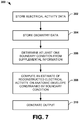
- FIG. 7 depicts an example of a method 300 to reconstruct electrical activity on an envelope using one or more boundary conditions.
- the method 300 can include storing electrical data (e.g., data 18, 58, 88, 170) representing electrical activity measured non-invasively at a plurality of surface measurement locations on a patient's body.
- the electrical data can be stored in a non-volatile or volatile memory structure.
- the method includes storing geometry data (e.g., data 20, 60, 90, 172).
- the geometry data can represent the geometry of patient anatomy, including the torso geometry and geometry of an anatomic envelope (e.g., cardiac envelope, such an epicardial envelope) within the patient's body.
- anatomic envelope e.g., cardiac envelope, such an epicardial envelope
- the surface measurement locations (e.g., corresponding to electrode locations) can also be registered in the geometry data.
- the electrical and geometry data can be stored in a non-volatile or volatile memory structure, which may be local memory or distributed (e.g., in a network system).
- one or more boundary conditions are determined (e.g., by boundary condition generator 24 or 112) based on supplemental information.
- the supplemental information and associated boundary condition may be fixed or variable over time.
- a fixed boundary condition can be represented as predetermined (or programmable) low voltage potential at one or more locations associated with the anatomic envelope of interest (e.g., corresponding to scar tissue or a lesion).
- a variable boundary condition can be represented as time-varying voltage potential that is measured (e.g., via one or more intracardiac electrodes) at one or more fixed or localized moving locations. The location can also be fixed or it can vary over time.
- Boundary conditions can be determined automatically or be selected in response to a user input. In some examples, a user may even specify a boundary condition (e.g., a fixed boundary condition) to simulate the effect of creating a lesion (e.g., via ablation) at region that otherwise is presently healthy.
- the method 300 includes computing reconstructed electrical activity (e.g., via reconstruction engine 16, 52, 82 or 180) for a plurality of locations residing on the anatomic envelope within the patient's body based on the electrical data and the geometry data.
- each valid boundary condition (from 308) may be imposed on the corresponding computations to improve the inverse problem.
- a corresponding output can be generated based on the reconstructed electrical activity for the anatomic region of interest.
- the output can be a three-dimensional anatomic map for one or more times or time intervals, such as disclosed herein.
- portions of the invention may be embodied as a method, data processing system, or computer program product. Accordingly, these portions of the present invention may take the form of an entirely hardware embodiment, an entirely software embodiment, or an embodiment combining software and hardware. Furthermore, portions of the invention may be a computer program product on a computer-usable storage medium having computer readable program code on the medium. Any suitable computer-readable medium may be utilized including, but not limited to, static and dynamic storage devices, hard disks, optical storage devices, and magnetic storage devices.
- These computer-executable instructions may also be stored in computer-readable memory that can direct a computer or other programmable data processing apparatus to function in a particular manner, such that the instructions stored in the computer-readable memory result in an article of manufacture including instructions which implement the function specified in the flowchart block or blocks.
- the computer program instructions may also be loaded onto a computer or other programmable data processing apparatus to cause a series of operational steps to be performed on the computer or other programmable apparatus to produce a computer implemented process such that the instructions which execute on the computer or other programmable apparatus provide steps for implementing the functions specified in the flowchart block or blocks.
Landscapes
- Health & Medical Sciences (AREA)
- Life Sciences & Earth Sciences (AREA)
- Engineering & Computer Science (AREA)
- Heart & Thoracic Surgery (AREA)
- Animal Behavior & Ethology (AREA)
- General Health & Medical Sciences (AREA)
- Biomedical Technology (AREA)
- Veterinary Medicine (AREA)
- Public Health (AREA)
- Biophysics (AREA)
- Molecular Biology (AREA)
- Surgery (AREA)
- Pathology (AREA)
- Medical Informatics (AREA)
- Physics & Mathematics (AREA)
- Cardiology (AREA)
- Physiology (AREA)
- Computer Vision & Pattern Recognition (AREA)
- Artificial Intelligence (AREA)
- Psychiatry (AREA)
- Signal Processing (AREA)
- Measurement And Recording Of Electrical Phenomena And Electrical Characteristics Of The Living Body (AREA)
- Nuclear Medicine, Radiotherapy & Molecular Imaging (AREA)
- Radiology & Medical Imaging (AREA)
- Electrotherapy Devices (AREA)
Claims (15)
- Verfahren, Folgendes umfassend:a) Speichern elektrischer Daten, die elektrische Aktivität darstellen, die nicht-invasiv an mehreren Oberflächenmessungsstellen auf einem Körper eines Patienten gemessen wird;b) Speichern von Geometriedaten, die die Oberflächenmessungsstellen und Geometrie der Patientenanatomie darstellen, einschließlich einer anatomischen Hülle innerhalb des Körpers des Patienten;c) Bestimmen wenigstens einer Randbedingung unter Verwendung ergänzender Informationen, die wenigstens einer ausgewähltenStelle zugehörig sind, die der anatomischen Hülle innerhalb des Körpers des Patienten zugehörig ist; undd) Berechnen der rekonstruierten elektrischen Aktivität für mehrere Stellen, die sich auf der anatomischen Hülle innerhalb des Körpers des Patienten basierend auf den elektrischen Daten und den Geometriedaten befinden, wobei die wenigstens eine Randbedingung auferlegt wird, um das Berechnen zu verbessern;
dadurch gekennzeichnet, dasse) die ergänzenden Informationen Informationen einschließen, die sich auf eine Stelle einer Narbe/Läsion aus einer Bildgebungsmodalität, einer direkten Sicht und/oder einer physikalischen Sonde beziehen. - Verfahren nach Anspruch 1, wobei die wenigstens eine Randbedingung als Reaktion auf eine Benutzereingabe bestimmt wird.
- Verfahren nach Anspruch 1 oder 2, wobei die wenigstens eine Randbedingung Stellen auf der anatomischen Hülle einschließt, die dem identifizierten anatomischen Bereich zugehörig sind.
- Verfahren nach Anspruch 1, 2 oder 3, wobei die ergänzenden Informationen anatomische Informationen für eine Narbe oder Läsion, intrakardiale elektrische Messungen, Bildgebungsdaten, Informationen, die der Abgabe einer kardialen Therapie zugehörig sind, und/oder Benutzereingabedaten umfassen.
- Verfahren nach Anspruch 1, 2, 3 oder 4, wobei das Bestimmen der wenigstens einen Randbedingung ferner Folgendes umfasst:Bestimmen einer Stelle auf der anatomischen Hülle für jede Randbedingung; undBestimmen eines Parameterwerts für jede Randbedingung.
- Verfahren nach Anspruch 5, wobei wenigstens die Stelle auf der anatomischen Hülle und/oder der Parameterwert für jede Randbedingung hinsichtlich Zeit festgelegt sind.
- Verfahren nach Anspruch 6, wobei die wenigstens eine Randbedingung einen Bereich einer kardialen Läsion umfasst, der der anatomischen Hülle zugehörig ist.
- Verfahren nach Anspruch 5, wobei die Stelle auf der anatomischen Hülle und der Parameterwert für jede Randbedingung hinsichtlich Zeit variabel sind.
- Verfahren nach Anspruch 8, wobei die wenigstens eine Randbedingung eine Messung der kardialen elektrischen Aktivität umfasst, die der Stelle auf der anatomischen Hülle zugehörig ist.
- Verfahren nach einem der vorhergehenden Ansprüche, wobei das Berechnen der rekonstruierten elektrischen Aktivität ferner ein Erweitern eines Gleichungssystems umfasst, um Gleichungen aufzunehmen, die jede Randbedingung für eine Teilmenge der Stellen darstellen, die sich auf der anatomischen Hülle innerhalb des Körpers des Patienten befinden.
- Verfahren nach einem der vorhergehenden Ansprüche, wobei die wenigstens eine Randbedingung basierend auf den ergänzenden Informationen bestimmt wird, die vor einem Messen der elektrischen Aktivität an mehreren Oberflächenmessungsstellen an dem Körper des Patienten erhalten wurden.
- Verfahren nach einem der vorhergehenden Ansprüche, wobei die wenigstens eine Randbedingung basierend auf den ergänzenden Informationen bestimmt wird, die gleichzeitig mit dem Messen der elektrischen Aktivität an mehreren Oberflächenmessungsstellen an dem Körper des Patienten erhalten werden.
- Verfahren nach Anspruch 1, ferner Folgendes umfassend:
Speichern von Daten, die elektrische Aktivität darstellen, die an einer bekannten Stelle gemessen wird, oder die wenigstens ein elektrisches Signal, das ein zuvor bestimmtes elektrisches Merkmal aufweist, darstellt, das an der bekannten Stelle geliefert wird; und Verwenden der gemessenen elektrischen Aktivität oder des zuvor bestimmten elektrischen Merkmals und der bekannten Stelle, um die wenigstens eine Randbedingung zu definieren. - Verfahren nach einem der vorhergehenden Ansprüche, ferner umfassend ein Erzeugen einer elektrokardiographischen Karte basierend auf der rekonstruierten elektrischen Aktivität für die anatomische Hülle innerhalb des Körpers des Patienten.
- System (10), Folgendes umfassend:
einen Randbedingungsgenerator (20), der programmiert ist, um eine oder mehrere Randbedingungen unter Verwendung ergänzender Informationen zu bestimmen, die wenigstens einer ausgewählten Stelle zugehörig sind, die einer anatomischen Hülle innerhalb eines Körpers eines Patienten zugehörig ist:ein Rekonstruktionsmotor (16), um die rekonstruierte elektrische Aktivität für mehrere Stellen zu berechnen, die sich auf der anatomischen Hülle innerhalb des Körpers des Patienten basierend auf elektrischen Daten befinden, die die elektrische Aktivität, die nicht-invasiv von Stellen an dem Körper des Patienten erfasst wird, darstellen, und Geometriedaten, die Stellen auf dem Körper des Patienten und räumliche Geometrie des Patienten darstellen, einschließlich der anatomischen Hülle innerhalb des Körpers des Patienten, wobei die eine oder die mehreren Randbedingungen auferlegt werden, um das Berechnen zu verbessern; undeinen Ausgangsgenerator, um Ausgangsdaten basierend auf der berechneten rekonstruierten elektrischen Aktivität bereitzustellen;dadurch gekennzeichnet, dass die ergänzenden Informationen Informationen einschließen, die sich auf eine Stelle einer Narbe/Läsion aus einer Bildgebungsmodalität, einer direkten Sicht und/oder einer physikalischen Sonde beziehen.
Priority Applications (1)
| Application Number | Priority Date | Filing Date | Title |
|---|---|---|---|
| EP20202270.3A EP3795075B1 (de) | 2013-12-12 | 2014-12-12 | Verwendung von ergänzungsinformationen zur verbesserung von lösungen inverser probleme |
Applications Claiming Priority (2)
| Application Number | Priority Date | Filing Date | Title |
|---|---|---|---|
| US201361915322P | 2013-12-12 | 2013-12-12 | |
| PCT/US2014/070079 WO2015089433A1 (en) | 2013-12-12 | 2014-12-12 | Using supplemental information to improve inverse problem solutions |
Related Child Applications (1)
| Application Number | Title | Priority Date | Filing Date |
|---|---|---|---|
| EP20202270.3A Division EP3795075B1 (de) | 2013-12-12 | 2014-12-12 | Verwendung von ergänzungsinformationen zur verbesserung von lösungen inverser probleme |
Publications (3)
| Publication Number | Publication Date |
|---|---|
| EP3079578A1 EP3079578A1 (de) | 2016-10-19 |
| EP3079578A4 EP3079578A4 (de) | 2017-08-23 |
| EP3079578B1 true EP3079578B1 (de) | 2020-10-21 |
Family
ID=53366983
Family Applications (2)
| Application Number | Title | Priority Date | Filing Date |
|---|---|---|---|
| EP20202270.3A Active EP3795075B1 (de) | 2013-12-12 | 2014-12-12 | Verwendung von ergänzungsinformationen zur verbesserung von lösungen inverser probleme |
| EP14870144.4A Active EP3079578B1 (de) | 2013-12-12 | 2014-12-12 | Verwendung von ergänzungsinformationen zur verbesserung der inverser problemlösungen |
Family Applications Before (1)
| Application Number | Title | Priority Date | Filing Date |
|---|---|---|---|
| EP20202270.3A Active EP3795075B1 (de) | 2013-12-12 | 2014-12-12 | Verwendung von ergänzungsinformationen zur verbesserung von lösungen inverser probleme |
Country Status (4)
| Country | Link |
|---|---|
| US (1) | US9918652B2 (de) |
| EP (2) | EP3795075B1 (de) |
| CN (1) | CN106255455B (de) |
| WO (1) | WO2015089433A1 (de) |
Families Citing this family (9)
| Publication number | Priority date | Publication date | Assignee | Title |
|---|---|---|---|---|
| EP2571419B1 (de) | 2010-05-18 | 2020-02-12 | Zoll Medical Corporation | Tragbare medizinische ambulanzvorrichtung mit mehreren erfassungselektroden |
| US11934752B1 (en) * | 2013-02-04 | 2024-03-19 | Comsol Ab | System and method for adding and defining perfectly matched layers for a model of a physical system |
| JP6937321B2 (ja) * | 2016-05-03 | 2021-09-22 | アクタス メディカル インクAcutus Medical,Inc. | 心臓情報動的表示システム |
| EP3651638B1 (de) | 2017-07-12 | 2022-04-27 | CardioInsight Technologies, Inc. | Bildgebung zur bestimmung von informationen über die geometrie von elektroden, die auf einen patienten verteilt werden |
| US11039776B2 (en) * | 2018-03-23 | 2021-06-22 | Cardioinsight Technologies, Inc. | Determining bipolar electrical activity |
| US11138792B2 (en) * | 2018-04-02 | 2021-10-05 | Cardioinsight Technologies, Inc. | Multi-dimensional method of fundamental solutions for reconstruction of electrophysiological activity |
| CN113226179B (zh) * | 2018-11-19 | 2024-08-30 | 科迪影技术股份有限公司 | 用于ecgi的图总变分 |
| US11691018B2 (en) * | 2021-02-19 | 2023-07-04 | Cardioinsight Technologies Inc. | Using implantable medical devices to augment noninvasive cardiac mapping |
| US11819331B2 (en) * | 2021-12-08 | 2023-11-21 | Biosense Webster (Israel) Ltd. | Visualization of epicardial and endocardial electroanatomical maps |
Family Cites Families (18)
| Publication number | Priority date | Publication date | Assignee | Title |
|---|---|---|---|---|
| WO1999005962A1 (en) * | 1997-07-31 | 1999-02-11 | Case Western Reserve University | A system and method for non-invasive electrocardiographic imaging |
| WO2003028801A2 (en) | 2001-10-04 | 2003-04-10 | Case Western Reserve University | Systems and methods for noninvasive electrocardiographic imaging (ecgi) using generalized minimum residual (gmres) |
| RS49856B (sr) | 2004-01-16 | 2008-08-07 | Boško Bojović | Uređaj i postupak za vizuelnu trodimenzionalnu prezentaciju ecg podataka |
| EP2436309B1 (de) | 2005-07-22 | 2021-03-17 | Case Western Reserve University | Nichtinvasives elektrokardiographisches Bild |
| US10362959B2 (en) | 2005-12-06 | 2019-07-30 | St. Jude Medical, Atrial Fibrillation Division, Inc. | System and method for assessing the proximity of an electrode to tissue in a body |
| WO2008085179A1 (en) | 2006-01-18 | 2008-07-17 | Newcardio, Inc. | Quantitative assessment of cardiac electrical events |
| WO2007134190A2 (en) | 2006-05-10 | 2007-11-22 | Regents Of The University Of Minnesota | Methods and apparatus of three dimensional cardiac electrophysiological imaging |
| JP5281570B2 (ja) | 2006-06-13 | 2013-09-04 | リズミア メディカル インコーポレイテッド | カテーテルの移動と複数心拍の統合を含む非接触式心臓マッピング |
| US9370312B2 (en) * | 2006-09-06 | 2016-06-21 | Biosense Webster, Inc. | Correlation of cardiac electrical maps with body surface measurements |
| FR2906123A1 (fr) * | 2006-09-25 | 2008-03-28 | Ela Medical Soc Par Actions Si | Procede de reconstruction d'un electrocardiogramme de surface a partir d'un electrogramme endocavitaire |
| WO2010019494A1 (en) | 2008-08-11 | 2010-02-18 | Washington University In St. Louis | Systems and methods for on-site and real-time electrocardiographic imaging (ecgi) |
| RU2409313C2 (ru) | 2008-11-27 | 2011-01-20 | Амиран Шотаевич РЕВИШВИЛИ | Способ неинвазивного электрофизиологического исследования сердца |
| US8571647B2 (en) | 2009-05-08 | 2013-10-29 | Rhythmia Medical, Inc. | Impedance based anatomy generation |
| US8682626B2 (en) | 2010-07-21 | 2014-03-25 | Siemens Aktiengesellschaft | Method and system for comprehensive patient-specific modeling of the heart |
| CA2827042A1 (en) * | 2011-02-11 | 2012-08-16 | Natalia Trayanova | System and method for planning a patient-specific cardiac procedure |
| US9129053B2 (en) | 2012-02-01 | 2015-09-08 | Siemens Aktiengesellschaft | Method and system for advanced measurements computation and therapy planning from medical data and images using a multi-physics fluid-solid heart model |
| GB2510452A (en) | 2013-01-31 | 2014-08-06 | Naviconix Ltd | Method of mapping the heart with a trackable electrode catheter |
| US11103174B2 (en) | 2013-11-13 | 2021-08-31 | Biosense Webster (Israel) Ltd. | Reverse ECG mapping |
-
2014
- 2014-12-12 EP EP20202270.3A patent/EP3795075B1/de active Active
- 2014-12-12 WO PCT/US2014/070079 patent/WO2015089433A1/en active Application Filing
- 2014-12-12 EP EP14870144.4A patent/EP3079578B1/de active Active
- 2014-12-12 US US14/569,145 patent/US9918652B2/en active Active
- 2014-12-12 CN CN201480074201.4A patent/CN106255455B/zh active Active
Non-Patent Citations (1)
| Title |
|---|
| None * |
Also Published As
| Publication number | Publication date |
|---|---|
| CN106255455B (zh) | 2019-08-16 |
| EP3795075A1 (de) | 2021-03-24 |
| EP3079578A1 (de) | 2016-10-19 |
| WO2015089433A1 (en) | 2015-06-18 |
| EP3795075B1 (de) | 2023-07-05 |
| US9918652B2 (en) | 2018-03-20 |
| EP3079578A4 (de) | 2017-08-23 |
| US20150164357A1 (en) | 2015-06-18 |
| CN106255455A (zh) | 2016-12-21 |
Similar Documents
| Publication | Publication Date | Title |
|---|---|---|
| EP3079578B1 (de) | Verwendung von ergänzungsinformationen zur verbesserung der inverser problemlösungen | |
| US11131536B2 (en) | Localization and tracking of an object | |
| EP3302261B1 (de) | Magnetische messung zur bereitstellung von geometriedaten | |
| JP6139518B2 (ja) | 心電図マッピングのための位置決め | |
| EP3198225B1 (de) | Ortung von objekten innerhalb eines leitfähigen volumens | |
| WO2018208896A1 (en) | Conduction velocity and pattern mapping | |
| EP3773169B1 (de) | Mehrdimensionales verfahren für grundlegende lösungen zur rekonstruktion von elektrophysiologischer aktivität | |
| US20230036977A1 (en) | Systems and Methods for Electrocardiographic Mapping and Target Site Identification | |
| EP3614913B1 (de) | Konnektivitätsanalyse für arrhythmietreiber | |
| US20210290138A1 (en) | Determining bipolar electrical activity | |
| EP4380455A1 (de) | Systeme und verfahren zur elektrokardiographischen abbildung und zielstellenidentifizierung |
Legal Events
| Date | Code | Title | Description |
|---|---|---|---|
| PUAI | Public reference made under article 153(3) epc to a published international application that has entered the european phase |
Free format text: ORIGINAL CODE: 0009012 |
|
| 17P | Request for examination filed |
Effective date: 20160711 |
|
| AK | Designated contracting states |
Kind code of ref document: A1 Designated state(s): AL AT BE BG CH CY CZ DE DK EE ES FI FR GB GR HR HU IE IS IT LI LT LU LV MC MK MT NL NO PL PT RO RS SE SI SK SM TR |
|
| AX | Request for extension of the european patent |
Extension state: BA ME |
|
| DAX | Request for extension of the european patent (deleted) | ||
| A4 | Supplementary search report drawn up and despatched |
Effective date: 20170724 |
|
| RIC1 | Information provided on ipc code assigned before grant |
Ipc: A61B 5/05 20060101AFI20170718BHEP |
|
| STAA | Information on the status of an ep patent application or granted ep patent |
Free format text: STATUS: EXAMINATION IS IN PROGRESS |
|
| 17Q | First examination report despatched |
Effective date: 20190527 |
|
| GRAP | Despatch of communication of intention to grant a patent |
Free format text: ORIGINAL CODE: EPIDOSNIGR1 |
|
| STAA | Information on the status of an ep patent application or granted ep patent |
Free format text: STATUS: GRANT OF PATENT IS INTENDED |
|
| INTG | Intention to grant announced |
Effective date: 20200519 |
|
| RAP1 | Party data changed (applicant data changed or rights of an application transferred) |
Owner name: CARDIOINSIGHT TECHNOLOGIES, INC. |
|
| GRAS | Grant fee paid |
Free format text: ORIGINAL CODE: EPIDOSNIGR3 |
|
| GRAA | (expected) grant |
Free format text: ORIGINAL CODE: 0009210 |
|
| STAA | Information on the status of an ep patent application or granted ep patent |
Free format text: STATUS: THE PATENT HAS BEEN GRANTED |
|
| AK | Designated contracting states |
Kind code of ref document: B1 Designated state(s): AL AT BE BG CH CY CZ DE DK EE ES FI FR GB GR HR HU IE IS IT LI LT LU LV MC MK MT NL NO PL PT RO RS SE SI SK SM TR |
|
| REG | Reference to a national code |
Ref country code: GB Ref legal event code: FG4D |
|
| REG | Reference to a national code |
Ref country code: CH Ref legal event code: EP |
|
| REG | Reference to a national code |
Ref country code: IE Ref legal event code: FG4D |
|
| REG | Reference to a national code |
Ref country code: DE Ref legal event code: R096 Ref document number: 602014071554 Country of ref document: DE |
|
| REG | Reference to a national code |
Ref country code: AT Ref legal event code: REF Ref document number: 1324982 Country of ref document: AT Kind code of ref document: T Effective date: 20201115 |
|
| REG | Reference to a national code |
Ref country code: AT Ref legal event code: MK05 Ref document number: 1324982 Country of ref document: AT Kind code of ref document: T Effective date: 20201021 |
|
| REG | Reference to a national code |
Ref country code: NL Ref legal event code: MP Effective date: 20201021 |
|
| PG25 | Lapsed in a contracting state [announced via postgrant information from national office to epo] |
Ref country code: GR Free format text: LAPSE BECAUSE OF FAILURE TO SUBMIT A TRANSLATION OF THE DESCRIPTION OR TO PAY THE FEE WITHIN THE PRESCRIBED TIME-LIMIT Effective date: 20210122 Ref country code: NO Free format text: LAPSE BECAUSE OF FAILURE TO SUBMIT A TRANSLATION OF THE DESCRIPTION OR TO PAY THE FEE WITHIN THE PRESCRIBED TIME-LIMIT Effective date: 20210121 Ref country code: PT Free format text: LAPSE BECAUSE OF FAILURE TO SUBMIT A TRANSLATION OF THE DESCRIPTION OR TO PAY THE FEE WITHIN THE PRESCRIBED TIME-LIMIT Effective date: 20210222 Ref country code: NL Free format text: LAPSE BECAUSE OF FAILURE TO SUBMIT A TRANSLATION OF THE DESCRIPTION OR TO PAY THE FEE WITHIN THE PRESCRIBED TIME-LIMIT Effective date: 20201021 Ref country code: RS Free format text: LAPSE BECAUSE OF FAILURE TO SUBMIT A TRANSLATION OF THE DESCRIPTION OR TO PAY THE FEE WITHIN THE PRESCRIBED TIME-LIMIT Effective date: 20201021 Ref country code: FI Free format text: LAPSE BECAUSE OF FAILURE TO SUBMIT A TRANSLATION OF THE DESCRIPTION OR TO PAY THE FEE WITHIN THE PRESCRIBED TIME-LIMIT Effective date: 20201021 |
|
| REG | Reference to a national code |
Ref country code: LT Ref legal event code: MG4D |
|
| PG25 | Lapsed in a contracting state [announced via postgrant information from national office to epo] |
Ref country code: SE Free format text: LAPSE BECAUSE OF FAILURE TO SUBMIT A TRANSLATION OF THE DESCRIPTION OR TO PAY THE FEE WITHIN THE PRESCRIBED TIME-LIMIT Effective date: 20201021 Ref country code: PL Free format text: LAPSE BECAUSE OF FAILURE TO SUBMIT A TRANSLATION OF THE DESCRIPTION OR TO PAY THE FEE WITHIN THE PRESCRIBED TIME-LIMIT Effective date: 20201021 Ref country code: IS Free format text: LAPSE BECAUSE OF FAILURE TO SUBMIT A TRANSLATION OF THE DESCRIPTION OR TO PAY THE FEE WITHIN THE PRESCRIBED TIME-LIMIT Effective date: 20210221 Ref country code: LV Free format text: LAPSE BECAUSE OF FAILURE TO SUBMIT A TRANSLATION OF THE DESCRIPTION OR TO PAY THE FEE WITHIN THE PRESCRIBED TIME-LIMIT Effective date: 20201021 Ref country code: BG Free format text: LAPSE BECAUSE OF FAILURE TO SUBMIT A TRANSLATION OF THE DESCRIPTION OR TO PAY THE FEE WITHIN THE PRESCRIBED TIME-LIMIT Effective date: 20210121 Ref country code: AT Free format text: LAPSE BECAUSE OF FAILURE TO SUBMIT A TRANSLATION OF THE DESCRIPTION OR TO PAY THE FEE WITHIN THE PRESCRIBED TIME-LIMIT Effective date: 20201021 Ref country code: ES Free format text: LAPSE BECAUSE OF FAILURE TO SUBMIT A TRANSLATION OF THE DESCRIPTION OR TO PAY THE FEE WITHIN THE PRESCRIBED TIME-LIMIT Effective date: 20201021 |
|
| PG25 | Lapsed in a contracting state [announced via postgrant information from national office to epo] |
Ref country code: HR Free format text: LAPSE BECAUSE OF FAILURE TO SUBMIT A TRANSLATION OF THE DESCRIPTION OR TO PAY THE FEE WITHIN THE PRESCRIBED TIME-LIMIT Effective date: 20201021 |
|
| REG | Reference to a national code |
Ref country code: DE Ref legal event code: R097 Ref document number: 602014071554 Country of ref document: DE |
|
| PG25 | Lapsed in a contracting state [announced via postgrant information from national office to epo] |
Ref country code: RO Free format text: LAPSE BECAUSE OF FAILURE TO SUBMIT A TRANSLATION OF THE DESCRIPTION OR TO PAY THE FEE WITHIN THE PRESCRIBED TIME-LIMIT Effective date: 20201021 Ref country code: SK Free format text: LAPSE BECAUSE OF FAILURE TO SUBMIT A TRANSLATION OF THE DESCRIPTION OR TO PAY THE FEE WITHIN THE PRESCRIBED TIME-LIMIT Effective date: 20201021 Ref country code: LT Free format text: LAPSE BECAUSE OF FAILURE TO SUBMIT A TRANSLATION OF THE DESCRIPTION OR TO PAY THE FEE WITHIN THE PRESCRIBED TIME-LIMIT Effective date: 20201021 Ref country code: SM Free format text: LAPSE BECAUSE OF FAILURE TO SUBMIT A TRANSLATION OF THE DESCRIPTION OR TO PAY THE FEE WITHIN THE PRESCRIBED TIME-LIMIT Effective date: 20201021 Ref country code: CZ Free format text: LAPSE BECAUSE OF FAILURE TO SUBMIT A TRANSLATION OF THE DESCRIPTION OR TO PAY THE FEE WITHIN THE PRESCRIBED TIME-LIMIT Effective date: 20201021 Ref country code: EE Free format text: LAPSE BECAUSE OF FAILURE TO SUBMIT A TRANSLATION OF THE DESCRIPTION OR TO PAY THE FEE WITHIN THE PRESCRIBED TIME-LIMIT Effective date: 20201021 |
|
| REG | Reference to a national code |
Ref country code: CH Ref legal event code: PL |
|
| PLBE | No opposition filed within time limit |
Free format text: ORIGINAL CODE: 0009261 |
|
| STAA | Information on the status of an ep patent application or granted ep patent |
Free format text: STATUS: NO OPPOSITION FILED WITHIN TIME LIMIT |
|
| PG25 | Lapsed in a contracting state [announced via postgrant information from national office to epo] |
Ref country code: DK Free format text: LAPSE BECAUSE OF FAILURE TO SUBMIT A TRANSLATION OF THE DESCRIPTION OR TO PAY THE FEE WITHIN THE PRESCRIBED TIME-LIMIT Effective date: 20201021 Ref country code: MC Free format text: LAPSE BECAUSE OF FAILURE TO SUBMIT A TRANSLATION OF THE DESCRIPTION OR TO PAY THE FEE WITHIN THE PRESCRIBED TIME-LIMIT Effective date: 20201021 |
|
| REG | Reference to a national code |
Ref country code: BE Ref legal event code: MM Effective date: 20201231 |
|
| 26N | No opposition filed |
Effective date: 20210722 |
|
| GBPC | Gb: european patent ceased through non-payment of renewal fee |
Effective date: 20210121 |
|
| PG25 | Lapsed in a contracting state [announced via postgrant information from national office to epo] |
Ref country code: AL Free format text: LAPSE BECAUSE OF FAILURE TO SUBMIT A TRANSLATION OF THE DESCRIPTION OR TO PAY THE FEE WITHIN THE PRESCRIBED TIME-LIMIT Effective date: 20201021 Ref country code: LU Free format text: LAPSE BECAUSE OF NON-PAYMENT OF DUE FEES Effective date: 20201212 Ref country code: IE Free format text: LAPSE BECAUSE OF NON-PAYMENT OF DUE FEES Effective date: 20201212 Ref country code: IT Free format text: LAPSE BECAUSE OF FAILURE TO SUBMIT A TRANSLATION OF THE DESCRIPTION OR TO PAY THE FEE WITHIN THE PRESCRIBED TIME-LIMIT Effective date: 20201021 |
|
| PG25 | Lapsed in a contracting state [announced via postgrant information from national office to epo] |
Ref country code: LI Free format text: LAPSE BECAUSE OF NON-PAYMENT OF DUE FEES Effective date: 20201231 Ref country code: SI Free format text: LAPSE BECAUSE OF FAILURE TO SUBMIT A TRANSLATION OF THE DESCRIPTION OR TO PAY THE FEE WITHIN THE PRESCRIBED TIME-LIMIT Effective date: 20201021 Ref country code: GB Free format text: LAPSE BECAUSE OF NON-PAYMENT OF DUE FEES Effective date: 20210121 Ref country code: CH Free format text: LAPSE BECAUSE OF NON-PAYMENT OF DUE FEES Effective date: 20201231 |
|
| PG25 | Lapsed in a contracting state [announced via postgrant information from national office to epo] |
Ref country code: IS Free format text: LAPSE BECAUSE OF FAILURE TO SUBMIT A TRANSLATION OF THE DESCRIPTION OR TO PAY THE FEE WITHIN THE PRESCRIBED TIME-LIMIT Effective date: 20210221 Ref country code: TR Free format text: LAPSE BECAUSE OF FAILURE TO SUBMIT A TRANSLATION OF THE DESCRIPTION OR TO PAY THE FEE WITHIN THE PRESCRIBED TIME-LIMIT Effective date: 20201021 Ref country code: MT Free format text: LAPSE BECAUSE OF FAILURE TO SUBMIT A TRANSLATION OF THE DESCRIPTION OR TO PAY THE FEE WITHIN THE PRESCRIBED TIME-LIMIT Effective date: 20201021 Ref country code: CY Free format text: LAPSE BECAUSE OF FAILURE TO SUBMIT A TRANSLATION OF THE DESCRIPTION OR TO PAY THE FEE WITHIN THE PRESCRIBED TIME-LIMIT Effective date: 20201021 |
|
| PG25 | Lapsed in a contracting state [announced via postgrant information from national office to epo] |
Ref country code: MK Free format text: LAPSE BECAUSE OF FAILURE TO SUBMIT A TRANSLATION OF THE DESCRIPTION OR TO PAY THE FEE WITHIN THE PRESCRIBED TIME-LIMIT Effective date: 20201021 |
|
| PG25 | Lapsed in a contracting state [announced via postgrant information from national office to epo] |
Ref country code: BE Free format text: LAPSE BECAUSE OF NON-PAYMENT OF DUE FEES Effective date: 20201231 |
|
| PGFP | Annual fee paid to national office [announced via postgrant information from national office to epo] |
Ref country code: FR Payment date: 20231122 Year of fee payment: 10 Ref country code: DE Payment date: 20231121 Year of fee payment: 10 |