EP3079462B1 - Länglicher trog - Google Patents
Länglicher trog Download PDFInfo
- Publication number
- EP3079462B1 EP3079462B1 EP14821495.0A EP14821495A EP3079462B1 EP 3079462 B1 EP3079462 B1 EP 3079462B1 EP 14821495 A EP14821495 A EP 14821495A EP 3079462 B1 EP3079462 B1 EP 3079462B1
- Authority
- EP
- European Patent Office
- Prior art keywords
- trough
- transverse wall
- long
- long trough
- transverse
- Prior art date
- Legal status (The legal status is an assumption and is not a legal conclusion. Google has not performed a legal analysis and makes no representation as to the accuracy of the status listed.)
- Active
Links
Images


Classifications
-
- A—HUMAN NECESSITIES
- A01—AGRICULTURE; FORESTRY; ANIMAL HUSBANDRY; HUNTING; TRAPPING; FISHING
- A01K—ANIMAL HUSBANDRY; AVICULTURE; APICULTURE; PISCICULTURE; FISHING; REARING OR BREEDING ANIMALS, NOT OTHERWISE PROVIDED FOR; NEW BREEDS OF ANIMALS
- A01K5/00—Feeding devices for stock or game ; Feeding wagons; Feeding stacks
- A01K5/01—Feed troughs; Feed pails
Definitions
- the present invention concerns a long trough for mounting under a partitioning between two stys, including a plurality of aligned, elongated trough elements adapted to be juxtaposed along a longitudinal direction, the long trough at each opposite end comprises an end wall arranged on an outermost trough element, the long trough further comprises at least one transverse wall arranged in an interposed position inside the long trough between the end walls, wherein the at least one transverse wall is extending transversely of the trough element.
- the application is typically for pigstys.
- the long trough may, however, also be used for other animals.
- the long trough is disposed under a sty separation/partitioning that can be of plastic planks, metal rods, or a similar design keeping the animals in two stys apart. Animals from two stys can thereby eat from the same long trough.
- the partitioning supports water pipes and feed pipes used for conducting water and feed as dry feed or wet feed to the long trough.
- the long trough is divided into sections that ensure space for a number of animals per section. These sections may each consist of a trough element typically having a length of 1 m to 1.3 m, and more specifically a length of 1.2 m. In pigstys is typically calculated with 0.33 m per pig at a trough.
- Trough elements in polymeric concrete it is, however, not possible to cast two end walls in a trough element due to the contraction occurring in the polymeric concrete. It is possible to cast troughs with an end wall at one end.
- Trough elements in polymeric concrete have hithertofore only been cast with the profile for bottom and sides and with an end wall. Bottom and sides can here constitute a curving shape which is approximately partly circular, or it may consist of several rectilinear section that define sidewalls and bottom in the trough. By this design, the end wall will have the same height as the upper edges of the sides of the trough element.
- a number of these elongated trough elements are juxtaposed in order to form the long trough.
- these trough elements are glued transverse walls to which the partitionings between the stys are mounted.
- end walls having a shape different from the shape of the transverse walls are made and glued on the outermost trough elements in order to constitute end walls in the long trough.
- problems with durability in the gluing have appeared.
- the gluing has been a separate process by which adapted transverse walls and end walls had to be mounted and held in fixtures. This has been a work-intensive process.
- brackets have been used extending across the long trough in order to mount the partitioning.
- the brackets are often a hazard for the pigs who can break their legs in these brackets since they extend beyond the sides of the long trough.
- DE 4444300 C1 discloses a trough element made of polymeric concrete and which is made with a transverse wall at the ends of the trough element. This transverse wall covers the bottom of the trough and does not allow alignment of several trough elements in continuation of each other with the possibility of wet feeding along the entire long trough with feeding by one feed pipe.
- FR 2628288 A1 discloses a separating barrier consisting of a series of longitudinal barrier elements held in place by a number of upright posts each having an elongated vertical slot for receiving the barrier elements.
- the posts and barrier elements are made of concrete for reducing corrosion and abrasion.
- the lower end of each post has a Y-shaped profile adapted to fit into a long trough arranged on the floor, where a central recess is formed between two projecting fingers of the lower end for enabling liquid food to pass under the post.
- the long trough comprises a plurality of trough elements of concrete aligned in the longitudinal direction.
- FR 2628288 A1 teaches that the barrier elements can be held in place by a central post and opposite end posts, each having a recess at the lower end.
- FR 2628288 A1 also teaches that the barrier elements can be held in place by only a central post, where the ends of the barrier plates are fixed to the walls of the building by means of support devices made of concrete or metal.
- the long trough being closed off at the ends, therefore separate end walls must be installed or the ends of the long trough must contact the walls of the building.
- transverse wall is cast together with the sides of the trough element as a single piece made of polymeric concrete, wherein the transverse wall has an open-ended slot at a top side of the transverse wall for receiving a portion of the partitioning, the transverse wall further has a height extending above upper edges of the sides of the trough element, and where a bottom side of the transverse wall is spaced apart from a bottom of the trough element thereby establishing an underrun.
- a slot is formed at the top side of the transverse wall, it is possible in a simple way to place an element of the partitioning to be used for sty separation. Thus there is no need to use separate brackets or to perform a breaking through of the long trough in order to mount the partitioning at a position above the long trough.
- the partitioning will usually be disposed at the centre of the long trough when looking in longitudinal direction such that the area of exposed trough is the same at both sides of the partitioning.
- the transverse wall extends at a distance above the upper edge of the sides of the trough elements, it is achieved that the slot can be given a large length such that the partitioning is supported along a considerable height.
- the length of the slot can be arbitrarily selected, depending on the support desired for the partitioning.
- the long trough according to the invention is peculiar in that the end walls of the outermost trough elements each has an open-ended slot at a top side of the end wall for receiving a portion of the partitioning, the end walls each further has a height extending above the upper edges of the sides of the outermost trough element.
- the end walls in the long trough can optionally be provided with a slot. According to the invention it will therefore also be preferred that the end walls, which are provided with a slot, extend at a distance above the upper edges of the sides of the trough element as well. An even better support of the partitioning than the support achieved by means of the transverse walls can hereby be achieved.
- the transverse wall is provided with its bottom side spaced apart from and above the bottom of the trough element.
- the long trough is made of polymeric concrete.
- the trough element can hereby be made entirely of polymeric concrete. It is preferred to make the transverse wall of polymeric concrete but it is possible by embedding in moulds to make the transverse walls of other materials which are embedded in the polymeric concrete.
- the long trough according to the invention is peculiar in that the transverse wall is disposed at one end of the trough element.
- each single trough element can be made as sections that are put together for forming the long trough with such a form that the transverse wall forms a wanted division of the long trough into individual eating sections with a length adapted to the intended use.
- the long trough according to the invention is peculiar in that the top side of the transverse wall extends from the upper edges of the sidewalls of the trough element with increasing height above the side edge towards the centre of the long trough.
- the transverse wall will hereby be in level with the upper side edge at the sides of the long trough and have a greater height at the centre of the long trough.
- the length of the slot can hereby be increased without need for the transverse walls extending up over the side edge right out at the joint between the sidewalls and the side edge.
- the width of the long trough may typically be from 400 mm to 480 mm, preferably 440 mm.
- the height from bottom to top of the transverse wall may typically be from 220 mm to 350 mm, preferably 260 mm.
- the height of the transverse wall is typically from 200 mm to 280 mm, but may also be higher.
- the length of the slot can typically be from 120 mm to 250 mm, but may also be greater.
- the long trough according to the invention is peculiar in that the slot at the top side of the transverse wall is disposed at the centre of the transverse wall and extends between 1/3 and 2/3 of the height of the transverse wall.
- a partitioning can be placed with a stabilising effect in the slot when the latter has some height. This is particularly the case when using a partitioning in the form of planks.
- planks can preferably be plastic planks.
- the long trough according to the invention is peculiar in that each trough element has a length between 0.02 m and 2 m. In a particular embodiment, the trough element has a length of 1.2 m.
- a trough element can be made with a length from 20 mm to 2000 mm.
- a long trough with a length of 6000 mm and divided by transverse walls over the entire length in order to provide sufficient support for a partitioning will therefore include the following trough elements:
- trough element with transverse wall which is 40 mm such that there is achieved an even distribution of wall supports in longitudinal direction of the long trough.
- each of the interposed trough elements have a transverse wall disposed at one end of the trough element, there is achieved an appropriate division into eating sections with a length of 1.20 m. This corresponds to the eating section for four pigs when the long trough is applied in a pigsty.
- the long trough according to the invention is peculiar in that the transverse wall is disposed at any point in longitudinal direction of the trough element.
- the long trough according to the invention is peculiar by including five trough elements.
- the long trough will have a length corresponding to a normal module in a sty construction in pig stables.
- the long trough according to the invention is peculiar in that a transverse wall has a length such that it can cover the entire cross-sectional profile of a trough element.
- Such a transverse wall can have an opening providing the underrun when used in an interposed position in the long trough. When used in an outer position as end wall in the long trough, the transverse wall can be closed towards the bottom.
- the long trough according to the invention is peculiar in that another transverse wall is disposed between two successive trough elements, where the transverse walls divide the long trough into individual eating sections.
- the transverse wall can be disposed between two successive trough elements such that the long trough is divided in that situation. This is advantageous when the two outermost trough elements are disposed with end walls facing outwardly in order to form end walls in a long trough.
- a transverse wall covering the entire cross-sectional profile of a trough element may also be used as end wall element and constitute an end wall in a long trough where all trough elements are positioned with the same orientation such that a transverse wall disposed at one end of a trough element is positioned in the same direction.
- the transverse wall with different height. It will thus be possible that the bottom side of the transverse wall in a central area is located at a lower position than adjacent parts of the bottom side of the transverse wall. The spacing between the bottom and the bottom side of the transverse wall can be limited thereby, obviating the risk of piglets getting stuck under the transverse wall.
- the bottom of the trough can be designed with a curving shape that is approximately circular.
- the trough can be designed with a V-shaped bottom.
- a V-shaped bottom can ensure a rapid feeding such that the time from the first feed leaving the feed pipe until the feed is present in the entire bottom of the long trough is minimised most. This is achieved due to the V-shape which provides a small surface in the bottom of the trough.
- the trough is V-shaped, it is particularly advantageous to have a transverse wall with varying height for the bottom side of the transverse wall. However, it is to be ensured that sufficient size of the opening is attained so as to provide certain through-flow of the wet feed.
- Fig. 1 shows a long trough 1 intended for disposition under a partitioning 2.
- the partitioning 2 delimits two stys as indicated by 3 and 4, which are intended for pigs.
- On the partitioning 2 is mounted a vertical feed pipe 5 divided into two branch pipes 6 that each have a mouth 7 at a position immediately over the long trough 1.
- the shown long trough consists of five eating sections 8. End walls 9 are provided in the long trough. Division of the long trough into individual sections is effected by means of four transverse walls 10 disposed inside the long trough. There is an opening 11 under each of the transverse walls between the bottom side 12 (see Fig. 4 ) of the transverse wall and the bottom 13 of the trough (see Fig. 4 ).
- the long trough is made of polymeric concrete and made of separate elongated trough elements, as will be explained in more detail below with reference to Figs. 5-11 .
- Fig. 3 shows a cross-sectional profile of the long trough 1. It appears that a curving wall 14 is provided, having a bottom 15 and sidewalls 16. Moreover, there is a base 17 used for positioning the trough on a floor.
- Fig. 2 appears a transverse wall 10' with a length such that it is capable of covering the entire cross-sectional profile for a trough element shown in Fig. 3 .
- the transverse wall 10' can therefore be used between two successive trough elements in order to constitute a transverse wall.
- Fig. 2 the transverse wall 10' is shown with an opening 18 corresponding to the opening 11 formed between the bottom side 12 of a transverse wall 10 and the bottom 13 of the long trough 1.
- Fig. 4 In Fig. 4 is seen long trough 1 where a transverse wall 10 is integrated by casting together with the sidewalls 16 of the long trough. An opening 11 therefore appears under the bottom side 12 of the transverse wall 10 and the bottom 15 of the trough.
- the top side 21 of the transverse wall 10 extends from the upper edges 22 of the sidewalls 16 of the trough element with increasing height above the side edge 22 towards the centre 23 of the long trough.
- the top side 21 of the transverse wall will hereby be in level with the upper side edge 21 at the sides of the long trough and have a greater height 24 at the centre 23 of the long trough.
- Gaps 11, 18 that are provided thus enable feed to flow throughout the entire length of the long trough under the transverse walls, irrespective of the presence of only two dispensing apertures 7 that distribute the feed to the five trough sections.
- the transverse wall 10, 10' has a slot 19.
- This slot is adapted to receive the partitioning 2.
- the partitioning will then be disposed in the slot in a way that appears from Fig. 1 .
- the partitioning 2 is therefore supported over its entire length by the engagement with the slot 19 only.
- the slot will have a length corresponding to about 2/3 of the height of the transverse wall 10, 10'.
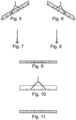
- the long trough is made of aligned, elongated trough elements. This will be explained in more detail with reference to Figs. 5-11 .
- the long trough 1 is made of five trough elements 20 and a partitioning 10'. All the trough elements 20 are therefore identical as they consist of a cross-sectional profile as shown in Fig. 3 , where a transverse wall 10 is provided at one end. The end walls 9 are closed at the two ends of the long trough. The other transverse walls 10 will be provided with an opening 11 as shown in Fig. 4 .
- the long trough 1 shown in Figs. 5-11 will thus be provided with closed end walls 9 and transverse walls that enable outflow and distribution of the feed along the entire length of the long trough.
- all sections 20 can be juxtaposed in longitudinal direction with the partitioning disposed with the same orientation, e.g. oriented to the right as shown on Fig. 5 .
- the end wall of the long trough disposed to the far left will be provided in the form of a separate transverse wall having a length such that it covers the entire cross-sectional profile of the trough element.
- the separate transverse wall located to the far left on Fig. 5 will in this situation be closed such that the long trough appears with a closed end wall.
- Fig. 12 shows a transverse wall 10' corresponding to the transverse wall 10 illustrated in Fig. 2 . It is seen here that the opening 18 is provided with rounded corners 25. Hereby is achieved easier cleaning compared with the tapering corners shown in the opening 18 in the embodiment shown in Fig. 2 .
- Fig. 12 the base 17 used for placing the trough on a floor is provided with inclining sidewalls 26.
- the sidewalls extend inclining outwards from the centre of the transverse wall 10", whereby cleaning is facilitated.
- Cutouts 27 are provided in the inclining sidewalls 26, used for mounting the trough. Angle braces and/or T-shaped inserts can therefore be used in the troughs.
- bases 17 shown in Figs. 2-4 may as well be provided with cutouts 27 in the sidewalls.
- Fig. 13 shows a third embodiment of a transverse wall 10′′′. This embodiment is particularly suited for piglets.
- the opening 18 will have less height than the openings shown in the previous Figures.
- the spacing 28 provided between the bottom 15 of the trough and the bottom side 18 of the transverse wall will be in the order of 30 mm. However, this spacing can vary from 20 to 40 mm.
- the height between the curved trough bottom and an upper bottom side 29 of the transverse wall at the two side edges will be in the order of 50-60 mm. It is hereby avoided that piglets can be injured under the transverse wall.
- Fig. 13 On Fig. 13 is seen that the base 17 is not only located under the trough.
- the base 17 is extended by side parts 17' extending beyond the sidewalls of the trough.
- a solid bottom extending along the entire length of the long trough.
- Fig. 14 shows a fourth embodiment of a transverse wall 10 ⁇ . This embodiment differs from the embodiment shown in Fig. 13 in that the base 17 is not provided with side parts.
- Fig. 15 shows a fifth embodiment of a transverse wall 10′′′ ⁇ .
- This transverse wall is, like the embodiment shown in Figs. 2 and 12 , intended for slaughter pigs.
- the openings 18 in this transverse wall 10 ⁇ ′′′ are provided a shape corresponding to the one illustrated in Fig. 13 .
- the distance 28 between the trough 15 and the bottom side 12 of the transverse wall is here in the order of 60 mm, but may vary from 50 to 70 mm. This ensures a sufficient flow through of the wet feed.
- the trough bottom 15 is V-shaped. This means that there is very small surface at the bottom. Hereby is achieved a more rapid feeding time, i.e. the time from the initial feed is leaving a feed pipe until feed is present over the entire bottom of the long trough.
Landscapes
- Life Sciences & Earth Sciences (AREA)
- Environmental Sciences (AREA)
- Birds (AREA)
- Animal Husbandry (AREA)
- Biodiversity & Conservation Biology (AREA)
- Laying Of Electric Cables Or Lines Outside (AREA)
- Electric Cable Installation (AREA)
- Panels For Use In Building Construction (AREA)
Claims (10)
- Länglicher Trog (1) zum Montieren unter einer Trennwand (2) zwischen zwei Ställen (3, 4), wobei der längliche Trog (1) eine Vielzahl von länglichen Trogelementen (20) beinhaltet, die dazu ausgelegt sind, entlang einer Längsrichtung nebeneinander positioniert zu werden, wobei der längliche Trog (1) an jedem gegenüberliegenden Ende eine Stirnwand (9) umfasst, die an einem äußersten Trogelement (20) angeordnet ist, jedes Trogelement ferner mindestens eine Querwand umfasst, die in einer Zwischenposition innerhalb des länglichen Trogs (1) zwischen den Stirnwänden (9) angeordnet ist, wobei sich die mindestens eine Querwand quer zu den Trogelementen (20) erstreckt, dadurch gekennzeichnet, dass eine Querwand (10, 10', 10'', 10‴, 10ʺʺ, 10ʺ‴) mit den Seiten (16) eines Trogelements (20) als ein einziges aus Polymerbeton hergestelltes Stück gegossen ist, wobei die Querwand (10, 10', 10'', 10‴, 10ʺʺ, 10‴ʺ) an einer Oberseite (21) der Querwand (10, 10', 10'', 10‴, 10ʺʺ, 10‴ʺ) einen offenendigen Schlitz (19) zum Aufnehmen eines Abschnitts der Trennwand (2) aufweist, wobei die Querwand (10, 10', 10'', 10‴, 10ʺʺ, 10‴ʺ) ferner eine sich über Oberkanten (22) der Seiten des Trogelements (20) erstreckende Höhe aufweist und wobei eine Unterseite der Querwand (10, 10', 10'', 10‴, 10ʺʺ, 10‴ʺ) von einem Boden (13, 15) des Trogelements (20) beabstandet ist, wodurch ein Unterlauf gebildet wird.
- Länglicher Trog (1) nach Anspruch 1, wobei die Querwand (10, 10', 10'', 10‴, 10,ʺʺ 10‴ʺ) an einem Ende des Trogelements (20) angeordnet ist.
- Länglicher Trog (1) nach Anspruch 1, wobei die Querwand (10, 10', 10'', 10‴, 10ʺʺ, 10‴ʺ) an beliebiger Stelle in der Längsrichtung des Trogelements (20) angeordnet ist.
- Länglicher Trog (1) nach Anspruch 1, wobei die Stirnwände (9) der äußersten Trogelemente (20) an einer Oberseite der Stirnwand (9) jeweils einen offenendigen Schlitz (19) zum Aufnehmen eines Abschnitts der Trennwand (2) aufweisen, wobei die Stirnwände (9) ferner jeweils eine sich über die Oberkanten (22) der Seiten des äußersten Trogelements (20) erstreckende Höhe aufweisen.
- Länglicher Trog (1) nach einem der vorhergehenden Ansprüche, wobei eine weitere Querwand zwischen zwei aufeinander folgenden Trogelementen (20) angeordnet ist, wobei die Querwände (10, 10', 10'', 10‴, 10ʺʺ, 10‴ʺ) den länglichen Trog (1) in einzelne Futtersegmente (8) unterteilen.
- Länglicher Trog (1) nach einem der vorhergehenden Ansprüche, wobei sich die Oberseite (21) der Querwand (10, 10', 10'', 10‴, 10ʺʺ, 10‴ʺ) von den Oberkanten (22) der Seiten (16) des Trogelements (20) in Richtung der Mitte (23) des länglichen Trogs (1) mit zunehmender Höhe über die Oberkanten (22) erstreckt.
- Länglicher Trog (1) nach einem der vorhergehenden Ansprüche, wobei der Schlitz (19) an der Oberseite (21) der Querwand (10, 10', 10", 10‴, 10ʺʺ, 10‴ʺ) in der Mitte der Querwand (10, 10', 10'', 10‴, 10ʺʺ, 10‴ʺ) angeordnet ist und sich zwischen 1/3 und 2/3 der Höhe der Querwand (10, 10', 10'', 10‴, 10ʺʺ, 10‴ʺ) erstreckt.
- Länglicher Trog (1) nach einem der vorhergehenden Ansprüche, wobei jedes Trogelement (20) eine Länge zwischen 1 m und 1,3 m, vorzugsweise eine Länge von 1,2 m, aufweist.
- Länglicher Trog (1) nach einem der vorhergehenden Ansprüche, wobei der längliche Trog (1) fünf Trogelemente (20) beinhaltet.
- Länglicher Trog (1) nach einem der vorhergehenden Ansprüche, wobei die Querwand (10, 10', 10'', 10‴, 10ʺʺ, 10‴ʺ) derart eine Länge in der Querrichtung aufweist, dass sie mindestens einen oberen Teil des Querschnittsprofils des Trogelements (20) abdeckt.
Applications Claiming Priority (2)
| Application Number | Priority Date | Filing Date | Title |
|---|---|---|---|
| DKPA201370763A DK178311B1 (en) | 2013-12-11 | 2013-12-11 | long Crib |
| PCT/DK2014/050425 WO2015086031A1 (en) | 2013-12-11 | 2014-12-11 | Long trough |
Publications (3)
| Publication Number | Publication Date |
|---|---|
| EP3079462A1 EP3079462A1 (de) | 2016-10-19 |
| EP3079462C0 EP3079462C0 (de) | 2025-05-21 |
| EP3079462B1 true EP3079462B1 (de) | 2025-05-21 |
Family
ID=52278325
Family Applications (1)
| Application Number | Title | Priority Date | Filing Date |
|---|---|---|---|
| EP14821495.0A Active EP3079462B1 (de) | 2013-12-11 | 2014-12-11 | Länglicher trog |
Country Status (3)
| Country | Link |
|---|---|
| EP (1) | EP3079462B1 (de) |
| DK (1) | DK178311B1 (de) |
| WO (1) | WO2015086031A1 (de) |
Families Citing this family (1)
| Publication number | Priority date | Publication date | Assignee | Title |
|---|---|---|---|---|
| EP3991548A1 (de) | 2020-10-29 | 2022-05-04 | Polysan A/S | Futtertrog, bodenplatte, system dafür und verfahren zum installieren des futtertroges |
Family Cites Families (6)
| Publication number | Priority date | Publication date | Assignee | Title |
|---|---|---|---|---|
| US792981A (en) * | 1904-09-12 | 1905-06-20 | Oliver H P Good | Hog-trough. |
| FR2547700B1 (fr) * | 1983-06-23 | 1986-06-13 | Fournier Sarl | Structure de separation pour l'alimentation d'animaux d'elevage |
| FR2595201B3 (fr) * | 1986-03-07 | 1988-03-11 | Queguiner Ind Sa | Barriere horizontale sur auge pour case d'engraissement |
| FR2628288A1 (fr) * | 1988-03-11 | 1989-09-15 | Thebault Ets Robert | Barriere de separation pour cage d'engraissement d'animaux |
| AT397902B (de) * | 1990-02-02 | 1994-08-25 | Braeuer Michael Ing | Futtertrog für schweine |
| DE4444300C1 (de) * | 1994-12-13 | 1996-03-21 | Durotec Stallbauelemente Gmbh | Futtereinrichtung für Mastschweine |
-
2013
- 2013-12-11 DK DKPA201370763A patent/DK178311B1/en active
-
2014
- 2014-12-11 EP EP14821495.0A patent/EP3079462B1/de active Active
- 2014-12-11 WO PCT/DK2014/050425 patent/WO2015086031A1/en not_active Ceased
Also Published As
| Publication number | Publication date |
|---|---|
| EP3079462A1 (de) | 2016-10-19 |
| EP3079462C0 (de) | 2025-05-21 |
| DK178311B1 (en) | 2015-11-30 |
| WO2015086031A1 (en) | 2015-06-18 |
| DK201370763A1 (da) | 2015-06-22 |
Similar Documents
| Publication | Publication Date | Title |
|---|---|---|
| US6691642B2 (en) | Feed trough | |
| US7726620B1 (en) | Vertical fuel tank support system | |
| US7930995B2 (en) | Bird feed tray | |
| US8646217B2 (en) | Device and methods for preventing the obstruction of gutters by leaves and other debris | |
| US4387666A (en) | Pig box grating | |
| EP3079462B1 (de) | Länglicher trog | |
| US5116256A (en) | Kennel run isolating means | |
| EP3162196B1 (de) | Gerilltes bodenelement für einen kuhstall, substrat und biegsame matte | |
| CA2625665C (en) | Feeder for animals | |
| KR200444185Y1 (ko) | 돈사의 바닥 보호판 | |
| RU2527551C2 (ru) | Экструдированный кормовой желоб с упрочненным краем | |
| EP2845472B1 (de) | Modulare Struktur für einen Stall und Stall mit solchen Struckuren | |
| JP7061676B2 (ja) | スラリーを収集及び除去するためのデバイス | |
| EP3011830A1 (de) | Vorgefertigtes modul für den boden eines viehstahls | |
| JP2003253716A (ja) | 排水口構造 | |
| US5876001A (en) | Apparatus for supporting cooling pipes and reinforcing bars for an ice rink | |
| KR101378937B1 (ko) | 전복 치패용 쉘터 | |
| KR101505986B1 (ko) | 인공어초 구조물 및 이를 이용한 낚시환경 조성구조물 | |
| WO1999056529A1 (en) | Standing cubicle partitions | |
| US6223692B1 (en) | Debris catching trough | |
| EP1855519B1 (de) | Fussbodenmatte zur verwendung durch tiere | |
| KR200466220Y1 (ko) | 양돈장 임신 스톨의 주철 바닥재 구조 | |
| GB2437598A (en) | Animal escape device | |
| CA3090337C (en) | Device for collection and removal of slurry | |
| EP1879447B1 (de) | Kleine voliere mit integrierter fütteranordnung |
Legal Events
| Date | Code | Title | Description |
|---|---|---|---|
| PUAI | Public reference made under article 153(3) epc to a published international application that has entered the european phase |
Free format text: ORIGINAL CODE: 0009012 |
|
| 17P | Request for examination filed |
Effective date: 20160614 |
|
| AK | Designated contracting states |
Kind code of ref document: A1 Designated state(s): AL AT BE BG CH CY CZ DE DK EE ES FI FR GB GR HR HU IE IS IT LI LT LU LV MC MK MT NL NO PL PT RO RS SE SI SK SM TR |
|
| AX | Request for extension of the european patent |
Extension state: BA ME |
|
| DAX | Request for extension of the european patent (deleted) | ||
| STAA | Information on the status of an ep patent application or granted ep patent |
Free format text: STATUS: EXAMINATION IS IN PROGRESS |
|
| 17Q | First examination report despatched |
Effective date: 20170314 |
|
| RAP1 | Party data changed (applicant data changed or rights of an application transferred) |
Owner name: POLYSAN A/S |
|
| GRAP | Despatch of communication of intention to grant a patent |
Free format text: ORIGINAL CODE: EPIDOSNIGR1 |
|
| STAA | Information on the status of an ep patent application or granted ep patent |
Free format text: STATUS: GRANT OF PATENT IS INTENDED |
|
| INTG | Intention to grant announced |
Effective date: 20241218 |
|
| GRAS | Grant fee paid |
Free format text: ORIGINAL CODE: EPIDOSNIGR3 |
|
| GRAA | (expected) grant |
Free format text: ORIGINAL CODE: 0009210 |
|
| STAA | Information on the status of an ep patent application or granted ep patent |
Free format text: STATUS: THE PATENT HAS BEEN GRANTED |
|
| AK | Designated contracting states |
Kind code of ref document: B1 Designated state(s): AL AT BE BG CH CY CZ DE DK EE ES FI FR GB GR HR HU IE IS IT LI LT LU LV MC MK MT NL NO PL PT RO RS SE SI SK SM TR |
|
| REG | Reference to a national code |
Ref country code: GB Ref legal event code: FG4D |
|
| REG | Reference to a national code |
Ref country code: CH Ref legal event code: EP |
|
| REG | Reference to a national code |
Ref country code: DE Ref legal event code: R096 Ref document number: 602014091959 Country of ref document: DE |
|
| REG | Reference to a national code |
Ref country code: IE Ref legal event code: FG4D |
|
| U01 | Request for unitary effect filed |
Effective date: 20250619 |
|
| U07 | Unitary effect registered |
Designated state(s): AT BE BG DE DK EE FI FR IT LT LU LV MT NL PT RO SE SI Effective date: 20250725 |
|
| PG25 | Lapsed in a contracting state [announced via postgrant information from national office to epo] |
Ref country code: ES Free format text: LAPSE BECAUSE OF FAILURE TO SUBMIT A TRANSLATION OF THE DESCRIPTION OR TO PAY THE FEE WITHIN THE PRESCRIBED TIME-LIMIT Effective date: 20250521 |
|
| PG25 | Lapsed in a contracting state [announced via postgrant information from national office to epo] |
Ref country code: GR Free format text: LAPSE BECAUSE OF FAILURE TO SUBMIT A TRANSLATION OF THE DESCRIPTION OR TO PAY THE FEE WITHIN THE PRESCRIBED TIME-LIMIT Effective date: 20250822 Ref country code: NO Free format text: LAPSE BECAUSE OF FAILURE TO SUBMIT A TRANSLATION OF THE DESCRIPTION OR TO PAY THE FEE WITHIN THE PRESCRIBED TIME-LIMIT Effective date: 20250821 |
|
| PG25 | Lapsed in a contracting state [announced via postgrant information from national office to epo] |
Ref country code: PL Free format text: LAPSE BECAUSE OF FAILURE TO SUBMIT A TRANSLATION OF THE DESCRIPTION OR TO PAY THE FEE WITHIN THE PRESCRIBED TIME-LIMIT Effective date: 20250521 |
|
| PG25 | Lapsed in a contracting state [announced via postgrant information from national office to epo] |
Ref country code: HR Free format text: LAPSE BECAUSE OF FAILURE TO SUBMIT A TRANSLATION OF THE DESCRIPTION OR TO PAY THE FEE WITHIN THE PRESCRIBED TIME-LIMIT Effective date: 20250521 |
|
| PG25 | Lapsed in a contracting state [announced via postgrant information from national office to epo] |
Ref country code: RS Free format text: LAPSE BECAUSE OF FAILURE TO SUBMIT A TRANSLATION OF THE DESCRIPTION OR TO PAY THE FEE WITHIN THE PRESCRIBED TIME-LIMIT Effective date: 20250821 |
|
| PG25 | Lapsed in a contracting state [announced via postgrant information from national office to epo] |
Ref country code: IS Free format text: LAPSE BECAUSE OF FAILURE TO SUBMIT A TRANSLATION OF THE DESCRIPTION OR TO PAY THE FEE WITHIN THE PRESCRIBED TIME-LIMIT Effective date: 20250921 |
|
| PG25 | Lapsed in a contracting state [announced via postgrant information from national office to epo] |
Ref country code: SM Free format text: LAPSE BECAUSE OF FAILURE TO SUBMIT A TRANSLATION OF THE DESCRIPTION OR TO PAY THE FEE WITHIN THE PRESCRIBED TIME-LIMIT Effective date: 20250521 |
|
| PG25 | Lapsed in a contracting state [announced via postgrant information from national office to epo] |
Ref country code: CZ Free format text: LAPSE BECAUSE OF FAILURE TO SUBMIT A TRANSLATION OF THE DESCRIPTION OR TO PAY THE FEE WITHIN THE PRESCRIBED TIME-LIMIT Effective date: 20250521 |
|
| PG25 | Lapsed in a contracting state [announced via postgrant information from national office to epo] |
Ref country code: SK Free format text: LAPSE BECAUSE OF FAILURE TO SUBMIT A TRANSLATION OF THE DESCRIPTION OR TO PAY THE FEE WITHIN THE PRESCRIBED TIME-LIMIT Effective date: 20250521 |
|
| U20 | Renewal fee for the european patent with unitary effect paid |
Year of fee payment: 12 Effective date: 20251229 |