EP3079170A1 - Lead frame, molding die, and method for manufacturing mounting component-attached lead frame - Google Patents
Lead frame, molding die, and method for manufacturing mounting component-attached lead frame Download PDFInfo
- Publication number
- EP3079170A1 EP3079170A1 EP13896193.3A EP13896193A EP3079170A1 EP 3079170 A1 EP3079170 A1 EP 3079170A1 EP 13896193 A EP13896193 A EP 13896193A EP 3079170 A1 EP3079170 A1 EP 3079170A1
- Authority
- EP
- European Patent Office
- Prior art keywords
- extension portion
- clamping portions
- pair
- clamping
- pressed
- Prior art date
- Legal status (The legal status is an assumption and is not a legal conclusion. Google has not performed a legal analysis and makes no representation as to the accuracy of the status listed.)
- Granted
Links
Images






Classifications
-
- H—ELECTRICITY
- H10—SEMICONDUCTOR DEVICES; ELECTRIC SOLID-STATE DEVICES NOT OTHERWISE PROVIDED FOR
- H10W—GENERIC PACKAGES, INTERCONNECTIONS, CONNECTORS OR OTHER CONSTRUCTIONAL DETAILS OF DEVICES COVERED BY CLASS H10
- H10W70/00—Package substrates; Interposers; Redistribution layers [RDL]
- H10W70/40—Leadframes
- H10W70/421—Shapes or dispositions
-
- H—ELECTRICITY
- H10—SEMICONDUCTOR DEVICES; ELECTRIC SOLID-STATE DEVICES NOT OTHERWISE PROVIDED FOR
- H10W—GENERIC PACKAGES, INTERCONNECTIONS, CONNECTORS OR OTHER CONSTRUCTIONAL DETAILS OF DEVICES COVERED BY CLASS H10
- H10W70/00—Package substrates; Interposers; Redistribution layers [RDL]
- H10W70/40—Leadframes
- H10W70/421—Shapes or dispositions
- H10W70/442—Shapes or dispositions of multiple leadframes in a single chip
-
- H—ELECTRICITY
- H10—SEMICONDUCTOR DEVICES; ELECTRIC SOLID-STATE DEVICES NOT OTHERWISE PROVIDED FOR
- H10W—GENERIC PACKAGES, INTERCONNECTIONS, CONNECTORS OR OTHER CONSTRUCTIONAL DETAILS OF DEVICES COVERED BY CLASS H10
- H10W74/00—Encapsulations, e.g. protective coatings
- H10W74/01—Manufacture or treatment
- H10W74/016—Manufacture or treatment using moulds
-
- H—ELECTRICITY
- H10—SEMICONDUCTOR DEVICES; ELECTRIC SOLID-STATE DEVICES NOT OTHERWISE PROVIDED FOR
- H10W—GENERIC PACKAGES, INTERCONNECTIONS, CONNECTORS OR OTHER CONSTRUCTIONAL DETAILS OF DEVICES COVERED BY CLASS H10
- H10W74/00—Encapsulations, e.g. protective coatings
- H10W74/10—Encapsulations, e.g. protective coatings characterised by their shape or disposition
- H10W74/111—Encapsulations, e.g. protective coatings characterised by their shape or disposition the semiconductor body being completely enclosed
-
- H—ELECTRICITY
- H10—SEMICONDUCTOR DEVICES; ELECTRIC SOLID-STATE DEVICES NOT OTHERWISE PROVIDED FOR
- H10W—GENERIC PACKAGES, INTERCONNECTIONS, CONNECTORS OR OTHER CONSTRUCTIONAL DETAILS OF DEVICES COVERED BY CLASS H10
- H10W70/00—Package substrates; Interposers; Redistribution layers [RDL]
- H10W70/40—Leadframes
- H10W70/464—Additional interconnections in combination with leadframes
- H10W70/468—Circuit boards
-
- H—ELECTRICITY
- H10—SEMICONDUCTOR DEVICES; ELECTRIC SOLID-STATE DEVICES NOT OTHERWISE PROVIDED FOR
- H10W—GENERIC PACKAGES, INTERCONNECTIONS, CONNECTORS OR OTHER CONSTRUCTIONAL DETAILS OF DEVICES COVERED BY CLASS H10
- H10W90/00—Package configurations
- H10W90/701—Package configurations characterised by the relative positions of pads or connectors relative to package parts
- H10W90/751—Package configurations characterised by the relative positions of pads or connectors relative to package parts of bond wires
- H10W90/754—Package configurations characterised by the relative positions of pads or connectors relative to package parts of bond wires between a chip and a stacked insulating package substrate, interposer or RDL
Definitions
- the present invention relates to a lead frame including one metal plate and the other metal plate joined to the one metal plate, a mold used for manufacturing such a lead frame, and a method of manufacturing a lead frame with a mounted component including such a lead frame.
- a mounted component such as a semiconductor device is placed on a lead frame and the mounted component is sealed with a resin (for example, Patent Document 1).
- the lead frame on which a mounted component is placed has a terminal like a press-fit terminal.
- the terminal and the mounted component to be sealed with a resin are connected to each other.
- a terminal and a location on which a mounted component is placed are formed on a single metal plate.
- Patent Document 1 JP2010-129795A
- the inventor of the present invention came up with an idea that one metal plate having a terminal and the other metal plate on which a mounted component is placed are manufactured separately from each other, and the one metal plate and the other metal plate are joined to each other into a single metal plate.
- a resin for sealing a mounted component leaks from a joint portion between the two metal plates.
- the present invention provides a lead frame that can prevent leakage of resin as much as possible, a mold used for manufacturing such a lead frame, and a method of manufacturing a lead frame with a mounted component including such a lead frame.
- a lead frame according to the present invention comprises:
- the first extension portion and the first clamping portions may have first positioning structures configured to position the first extension portion and the first clamping portions with each other; and the second extension portion and the second clamping portions may have second positioning structures configured to position the second extension portion and the second clamping portions with each other.
- an end of the first extension portion may be pressed to be extended, so that the first extension portion is positioned with respect to the first clamping portions; and an end of the second extension portion may be pressed to be extended, so that the second extension portion is positioned with respect to the second clamping portions.
- the one metal plate may include a second connection portion connected to the terminal, a third extension portion disposed on one end of the second connection portion to extend from the second connection portion in the first direction, and a fourth extension portion disposed on the other end of the second connection portion to extend from the second connection portion in the second direction; and the other metal plate may include a pair of third clamping portions configured to clamp the third extension portion, and a pair of fourth clamping portions configured to clamp the fourth extension portion.
- the third extension portion and the third clamping portions may have third positioning structures configured to position the third extension portion and the third clamping portions with each other; and the fourth extension portion and the fourth clamping portions may have fourth positioning structures configured to position the fourth extension portion and the fourth clamping portions.
- an end of the third extension portion may be pressed to be extended, so that the third extension portion is positioned with respect to the third clamping portions; and an end of the fourth extension portion may be pressed to be extended, so that the fourth extension portion is positioned with respect to the fourth clamping portions.
- a site, which is pressed by the mold, in one first clamping portion and a site, which is pressed by the mold, in the other first clamping portion may be located to be opposed to each other; and a site, which is pressed by the mold, in one second clamping portion and a site, which is pressed by the mold, in the other second clamping portion may be located to be opposed to each other.
- each portion of the pair of first clamping portions may be pressed to be extended by the mold at sites different from the sites of the pair of first clamping portions at which the resin is prevented from leaking from between the first extension portion and the first clamping portions, so that the first extension portion is positioned with respect to the first clamping portions; and each portion of the pair of second clamping portions may be pressed to be extended by the mold at sites different from the sites of the pair of second clamping portions at which the resin is prevented from leaking from between the second extension portion and the second clamping portions, so that the second extension portion is positioned with respect to the second clamping portions.
- the first direction and the second direction may be perpendicular to a direction in which the terminal is extended.
- a mold according to the present invention is a mold used when a resin is provided onto the mounted component on the lead frame described above, the mold comprising:
- a method of manufacturing a lead frame with a mounted component according to the present invention comprises:
- each portion of the pair of first clamping portions is pressed to be extended by the mold, which is used for sealing the mounted component with a resin, so that the gaps between the first extension portion and the first clamping portions are filled, whereby the resin supplied into the mold can be prevented from leaking from between the first extension portion and the first clamping portions.
- each portion of the pair of second clamping portions is pressed to be extended by the mold, so that the gaps between the second extension portion and the second clamping portions are filled, whereby the resin supplied into the mold can be prevented from leaking from between the second extension portion and the second clamping portions. Therefore, even when the one metal plate and the other metal plate are joined to each other into a single metal plate as in the present invention, the possibility of leaking out of the resin supplied into the mold can be reduced as much as possible.
- Figs. 1 to 8 are views for explaining the first embodiment of the present invention.
- a lead frame with a mounted component in this embodiment includes: one metal plate 10 having a plurality of terminals 15; and the other metal plate 50 joined to the one metal plate 10, with a mounted component 91, such as an IC chip, being placed thereon.
- the one metal plate 10 is plated as a whole.
- a mounted substrate 90 on which the mounted component 91 is placed is disposed on the other metal plate 50.
- each terminal 15 of the one metal plate 10 and the mounted component 91 or a circuit (not shown) on the mounted plate 90 are connected to each other through a wire 96.
- the other metal plate 50 is, for example, a copper plate, while the one metal plate 10 is formed by plating a metal plate made of a phosphorus bronze material.
- a plating for the one metal plate 10 a distal end side of each terminal 15 (upper side in Fig. 1 ) is plated with a first plating such as a tin plating, and the remaining part is plated with a second plating such as nickel plating.
- plating is firstly carried out by the second plating such as a nickel plating, and the distal side end of the terminal 15 is then plated with the first plating such as a tin plating.
- the first metal plate 10 includes a first connection portion 11 that connects the plurality of terminals 15 to each other, a first extension portion 12 disposed on one end of the first connection portion 11 to extend from the first connection portion 11 in a first direction (right direction in Fig. 1 ), and a second extension portion 13 disposed on the other end of the first connection portion 11 to extend from the first connection portion 11 in a second direction (left direction in Fig. 1 ) containing a component opposite to the first direction.
- description is made on the assumption that the second direction is opposed to the first direction, it should be noted that this is a mere example.
- each of the first direction and the second direction is perpendicular to a direction in which each terminal 15 is extended (up and down direction in Fig. 1 ), it should be noted that this is also a mere example.
- the other metal plate 50 includes a first fitting portion 51 having a pair of first clamping portions 62 configured to clamp the first extension portion 12, and a second fitting portion 52 having a pair of clamping portions 63 configured to clamp the second extension portion 13.
- each portion of the pair of first clamping portions 62 is pressed to be extended by a mold 100, which is used for sealing the mounted component 91 with a resin, so that gaps G (see Fig. 6 ) between the first extension portion 12 and the first clamping portions 62 are filled, whereby the resin is prevented from leaking from between the first extension portion 12 and the first clamping portions 62.
- each portion of the pair of second clamping portions 63 is pressed to be extended by the mold 100, so that gaps G (see Fig. 8 ) between the second extension portion 13 and the second clamping portions 63 are filled, whereby the resin is prevented from leaking from between the second extension portion 13 and the second clamping portions 63.
- the first extension portion 12 and the first clamping portions 62 have first positioning structures 16 and 66 configured to position the first extension portion 12 and the first clamping portions 62 with each other.
- the second extension portion 13 and the second clamping portions 63 have second positioning structures 18 and 68 configured to position the second extension portion 13 and the second clamping portions 63 with each other.
- the first extension portion 12 has a first narrow portion 16 having a smaller width, and a first wide portion 17 extended from the first narrow portion 16 toward a distal end side and having a larger width than that of the first narrow portion 16.
- the first fitting portion 51 has a pair of first projection portions 66 disposed on the first clamping portions 62 to correspond to the first narrow portion 16, and a first depression portion 67 corresponding to the first wide portion 17.
- the first narrow portion 16 is positioned between the pair of first projection portions 66, so that the first extension portion 12 and the first clamping portions 62 are positioned with each other.
- the second extension portion 13 has a second narrow portion 18 having a smaller width, and a second wide portion 19 extended from the second narrow portion 18 toward a distal end side and having a larger width than that of the second narrow portion 18.
- the second fitting portion 52 has a pair of second projection portions 68 disposed on the second clamping portions 63 to correspond to the second narrow portion 18 and a second depression portion 69 corresponding to the second wide portion 19.
- the second narrow portion 18 is positioned between the pair of second projection portions 68, so that the second extension portion 13 and the second clamping portions 63 are positioned with each other.
- an end of the first extension portion 12, i.e., the first wide portion 17 is pressed to be extended, so that the first extension portion 12 is positioned with respect to the first clamping portions 62 (see Figs. 1 and 2 ).
- an end of the second extension portion 13, i.e., the second wide portion 19 is pressed to be extended, so that the second extension portion 13 is positioned with respect to the second clamping portions 63.
- the first wide portion 17 of the first extension portion 12 is pressed to be horizontally extended, so that the first wide portion 17 comes into contact with the fist depression portion 67 of the first fitting portion 51.
- the first wide portion 17 of the first extension portion 12 is caulked to the first depression portion 67, so that the first extension portion 12 is positioned with respect to the first clamping portions 62.
- the second wide portion 19 of the second extension portion 13 is pressed to be horizontally extended, so that the second wide portion 19 comes into contact with the second depression portion 69 of the second fitting portion 52.
- the second wide portion 19 of the second extension portion 13 is caulked to the second depression portion 69, so that the second extension portion 13 is positioned with respect to the second clamping portions 63.
- the one metal plate 10 in this embodiment includes a second connection portion 21 connected to the terminals 15, a third extension portion 22 disposed on one end of the second connection portion 21 to extend from the second connection portion 21 in the first direction (right direction in Fig. 1 ), and a fourth extension portion 23 disposed on the other end of the second connection portion 21 to extend from the second connection portion 21 in the second direction.
- the other metal plate 50 includes a third fitting portion 53 having a pair of third clamping portions 72 configured to clamp the third extension portion 22, and a fourth fitting portion 54 having a pair of fourth clamping portions 73 configured to clamp the fourth extension portion 23.
- the third extension portion 22 and the third clamping portions 72 have third positioning structures 26 and 76 configured to position the third extension portion 22 and the third clamping portions 72 with each other.
- the fourth extension portion 23 and the fourth clamping portions 73 have fourth positioning structures 28 and 78 configured to position the fourth extension portion 23 and the fourth clamping portions 73 with each other.
- the third extension portion 22 has a third narrow portion 26 having a smaller width, and a third wide portion 27 extended from the third narrow portion 26 toward a distal end side and having a larger width than that of the third narrow portion 26.
- the third fitting portion 53 has a pair of third projection portions 76 disposed on the third clamping portions 72 to correspond to the third narrow portion 26, and a third depression portion 77 corresponding to the third wide portion 27.
- the third narrow portion 26 is positioned between the pair of third projection portions 76, so that the third extension portion 22 and the third clamping portions 72 are positioned with each other.
- the fourth extension portion 23 has a fourth narrow portion 28 having a smaller width, and a fourth wide portion 29 extended from the fourth narrow portion 28 toward a distal end side and having a lager width than that of the fourth narrow portion 28.
- the fourth fitting portion 54 has a pair of fourth projection portions 78 disposed on the fourth clamping portions 73 to correspond to the fourth narrow portion 28, and a fourth depression portion 79 corresponding to the fourth wide portion 29.
- the fourth narrow portion 28 is positioned between the pair of fourth projection portions 78, so that the fourth extension portion 23 and the fourth clamping portions 73 are positioned with each other.
- the third wide portion 27 of the third extension portion 22 is pressed to be horizontally extended, so that the third wide portion 27 comes into contact with the third depression portion 77.
- the third wide portion 27 of the third extension portion 22 is caulked to the third depression portion 77, so that the third extension portion 22 is positioned with respect to the third clamping portions 72.
- the fourth wide portion 29 of the fourth extension portion 23 is pressed to be horizontally extended, so that the fourth wide portion 29 comes into contact with the fourth depression portion 79.
- the fourth wide portion 29 of the fourth extension portion 23 is caulked to the fourth depression portion 79, so that the fourth extension portion 23 is positioned with respect to the fourth clamping portions 73.
- a site 62a 1 which is pressed by the mold 100, in one first clamping portion 62 and a site 62a 2 , which is pressed by the mold 100, in the other first clamping portion are located along a straight line extending in a direction in which the terminal 15 is extended (on the straight line extending in the up and down direction in Fig. 1 ) to be opposed to each other.
- Fig. 4(a) a site 62a 1 , which is pressed by the mold 100, in one first clamping portion 62 and a site 62a 2 , which is pressed by the mold 100, in the other first clamping portion are located along a straight line extending in a direction in which the terminal 15 is extended (on the straight line extending in the up and down direction in Fig. 1 ) to be opposed to each other.
- Fig. 4(a) a site 62a 1 , which is pressed by the mold 100, in one first clamping portion 62 and a site 62a 2 , which is pressed
- a site 63a 1 which is pressed by the mold 100, in one second clamping portion 63 and a site 63a 2 , which is pressed by the mold 100, in the other second clamping portion 63 are located along a straight line extending in a direction in which the terminal 15 is extended (on the straight line extending in the up and down direction in Fig. 1 ) to be opposed to each other.
- the mold 100 which is used when a resin is provided onto the mounted component 91 placed on the lead frame in this embodiment, has a pair of first protrusion portions 102a 1 and 102a 2 configured to press each portion of the pair of first clamping portions 62 and a pair of second protrusion portions 103a 1 and 103a 2 configured to press each portion of the pair of second clamping portions 63.
- the predetermined site 62a 1 of the one first clamping unit 62 is pressed by the one first protrusion portion 102a 1
- the predetermined side 62a 2 of the other first clamping portion 62 is pressed by the other first protrusion portion 102a 2 .
- a predetermined site 63a 1 of the one second clamping portion 63 is pressed by one second protrusion portion 103a 1
- a predetermined site 63a 2 of the other second clamping portion 63 is pressed by the other second protrusion portion 103a 2 .
- the one metal plate 10, which is plated as a whole, and the other metal plate 50 are prepared.
- the one metal plate 10 is plated as a whole, and the mounted substrate 90 on which the mounted component 91 is placed is joined to the other metal plate 50.
- first extension portion 12 is positioned between the pair of first clamping portions 62
- second extension portion 13 is positioned between the pair of second clamping portions 63
- third extension portion 22 is positioned between the pair of third clamping portions 72
- fourth extension portion 23 is positioned between the pair of fourth clamping portions 73 (see Figs. 1 and 2 ).
- the first wide portion 17 of the first extension portion 12 is pressed to be extended so that the first wide portion 17 is caulked to the first depression portion 67, whereby the first extension portion 12 is positioned with respect to the first clamping portions 62.
- the second wide portion 19 of the second extension portion 13 is pressed to be extended so that the second wide portion 19 is caulked to the second depression portion 69, whereby the second extension portion 13 is positioned with respect to the second clamping portions 63.
- the third wide portion 27 of the third extension portion 22 is pressed to be extended so that the third wide portion 27 is caulked to the third depression portion 77, whereby the third extension portion 22 is positioned with respect to the third clamping portions 72.
- the fourth wide portion 29 of the fourth extension unit 23 is pressed to be extended so that the fourth wide portion 29 is caulked to the fourth depression portion 79, whereby the fourth extension portion 23 is positioned with respect to the fourth clamping portions 73.
- the respective extension portions 12, 13, 22 and 23 are positioned between the respective clamping portions 62, 63, 72 and 73, and the respective extension portions 12, 13, 22 and 23 are caulked to the respective depression portions 67, 69, 77 and 79, whereby the one metal plate 10 is positioned with respect to the other metal plate 50.
- the first extension portion 12 is welded to the first fitting portion 51 by laser, for example.
- the second extension portion 13 is welded to the second fitting portion 52 by laser, for example.
- the third extension portion 22 is welded to the third fitting portion 53 by laser, for example.
- the fourth extension portion 23 is welded to the fourth fitting portion 54 by laser, for example.
- the one metal plate 10 is joined to the other plate 50.
- each of the terminals 15 of the one metal plate 10 and the mounted component 91 or a circuit (not shown) on the mounted substrate 90 are connected to each other through the wire 96.
- the mounted component 91 on the lead frame is surrounded by the mold 100 (see Fig. 3 ).
- the predetermined sites 62a 1 and 62a 2 of the pair of first clamping portions 62 is pressed to be extended by the first protrusion portions 102a 1 and 102a 2 of the mold 100, so that the gaps G between the first extension portion 12 and the first clamping portions 62 are filled (see Figs. 5 and 6 ).
- the predetermined sites 63a 1 and 63a 2 of the pair of second clamping portions 63 is pressed to be extended by the pair of second protrusion portions 103a 1 and 103a 2 of the mold 100, so that the gaps G between the second extension portion 13 and the second clamping portions 63 are filled (see Figs. 7 and 8 ).
- a resin is supplied into the mold 100, so that the mounted component 91 is sealed with the resin.
- the predetermined sites 62a 1 and 62a 2 of the pair of first clamping portions 62 is pressed to be extended by the pair of first protrusion portions 102a 1 and 102a 2 of the mold 100, so that the gaps G between the first extension portion 12a and the first clamping portions 62 are filled.
- the supplied resin is prevented from leaking out from between the first extension portion 12 and the first clamping portions 62 (see Figs. 5 and 6 ).
- the predetermined sites 63a 1 and 63a 2 of the pair of second clamping portions 63 is pressed to be extended by the pair of second protrusion potions 103a 1 and 103a 2 of the mold 100, so that the gaps G between the second extension portion 13 and the second clamping portions 63 are filled.
- the supplied resin is prevented from leaking out from between the second extension portion 13 and the second clamping portions 63 (see Figs. 7 and 8 ).
- the resin supplied into the mold 100 is cured, whereby the lead frame with a mounted component including the resin-sealed mounted component 91 is completed. After the resin has been cured, the mold 100 is removed.
- an electric conductivity and an elastic modulus are reversely correlated to each other. Namely, a copper material having a high electric conductivity has a low elastic modulus, while a copper material having a high elastic modulus and a spring property has a low electric conductivity. Thus, in a conventional lead frame made of one material, it is difficult to have both a high electric conductivity and a high elastic modulus.
- the inventor of the present invention came up with an idea that two kinds of metal plates made of different materials, which are joined to each other by laser welding, is used as a lead frame.
- the metal plates are plated.
- the plating is re-melted.
- a base metal may be exposed and/or a metal surface may have irregularities, which invites defective mounting.
- the one metal plate 10 is plated, and the mounted component 91, such as an IC chip, is reflow-soldered to the other metal plate 50. Only the other metal plate 50 is reflown and thus it is not necessary to reheat the one plated metal plate 10 so as to re-melt the plating. Thus, the re-melting of the plating of the one metal plate 10 can be avoided, whereby the defective mounting can be prevented from occurring.
- the lead frame In order that the lead frame is plated as a whole, it can be considered that a lead frame wound in a roll is fed out and immersed in a plating liquid such that the lead frame is plated, and that the plated lead frame is wound in a roll again.
- the overall lead frame may be bent (coil set occurs) so that defective assemblage during manufacturing steps occurs and/or that size precision of a completed product is deteriorated.
- disadvantage caused by bending can be reduced as much as possible.
- since only the one metal plate 10 is bent it does not take a lot of time and effort to straighten the bending.
- the terminal 15 such as a press fit pin
- a strict positioning precision is required for a distal end of the terminal 15.
- a more strict size precision is required.
- the one metal plate 10 is positioned with respect to the other plate 50 by various methods described below.
- a requirement for strict size precision can be satisfied.
- each portion of the pair of clamping portions 62 is pressed to be extended by the mold 100, which is used for sealing the mounted component 91 with a resin, so that the gaps G between the first extension portion 12 and the first clamping portions 62 are filled, whereby the resin supplied into the mold 100 is prevented from leaking from between the first extension portion 12 and the first clamping portions 62 (see Figs. 5 and 6 ).
- each portion of the pair of second clamping portions 63 is pressed to be extended by the mold 100, so that the gaps between the second extension portion 13 and the second clamping portions 63 are filled, whereby the resin supplied into the model 100 is prevented from leaking from between the second extension portion 13 and the second clamping portions 63 (see Figs.
- an amount of extension of the one first clamping portion 62 and an amount of extension of the other first clamping portion 62 are equal to each other.
- an amount of extension of the one second clamping portion 63 and an amount of extension of the other second clamping portion 63 are equal to each other. This is because, according to this aspect, occurrence of shifting in the direction in which the terminal 15 is extended (up and down direction in Fig. 3 ) of the one metal plate 10 with respect to the other metal plate 50 can be prevented.
- first extension portion 12 and the second extension portion 13 are pressed to be extended by the mold 100.
- first wide portion 17 of the first extension portion 12 is pressed to be extended to come into contact with the first depression portion 67, so that the first wide portion 17 of the first extension portion 12 is caulked to the first depression portion 67.
- second wide portion 19 of the second extension portion 13 is pressed to be extended to come into contact with the second depression portion 69, so that the second wide portion 19 of the second extension portion 13 is caulked to the second depression portion 69.
- the respective first extension portion 12 and the second extension portion 13 do not have sufficient thicknesses to be further extended by the mold 100.
- the first extension portion 12 and the first clamping portions 62 have the first positioning structures 16 and 66 configured to position the first extension portion 12 and the first clamping portion 62 with each other, and the second extension portion 13 and the second clamping portions 63 have the second positioning structures 18 and 68 configured to position the second extension portion 13 and the second clamping portions 63 with each other (see Figs. 1 and 2 ).
- the one metal plate 10 can be positioned with respect to the other metal plate 50 at both ends of the one metal plate 10.
- the first narrow portion 16 is positioned between the pair of first projection portions 66, so that the first extension portion 12 and the first clamping portions 62 are positioned with each other.
- the second narrow portion 18 is positioned between the pair of second projection portions 68, so that the second extension portion 13 and the second clamping portions 63 are positioned with each other.
- the one metal plate 10 can be positioned with respect to the other metal plate 50 by a simple manner.
- the first wide portion 17 of the first extension portion 12 is pressed to be extended, so that the first extension portion 12 is positioned with respect to the first clamping portions 62.
- the second wide portion 19 of the second extension portion 13 is pressed to be extended, so that the second extension portion 13 is positioned with respect to the second clamping portions 63.
- the one metal plate 10 is more precisely positioned with respect to the metal plate 50 at both ends of the one metal plate 10.
- the third extension portion 22 and the third clamping portions 72 have the third positioning structures 26 and 76 configured to position the third extension portion 22 and the third clamping portions 72 with each other, and the fourth extension portion 23 and the fourth clamping portions 73 have the fourth positioning structures 28 and 78 configured to position the fourth extension portion 23 and the fourth clamping portions 73 with each other (see Figs. 1 and 2 ).
- the one metal plate 10 can be positioned with respect to the other metal plate 50 at four corners of the one metal plate 10, the precise positioning can be expected.
- the third narrow portion 26 is positioned between the third projection portions 76, so that the third extension portion 22 and the third clamping portions 72 are positioned with each other, and the fourth narrow portion 28 is positioned between the pair of fourth projection portions 78, so that the fourth extension portion 23 and the fourth clamping portions 73 are positioned with each other.
- the one metal plate 10 can be positioned with respect to the other metal plate 50 in a simple manner.
- the third wide portion 19 of the third extension portion 22 is pressed to be extended, so that the third extension portion 22 is positioned with respect to the third clamping portions 72.
- the fourth wide portion 29 of the fourth extension portion 23 is pressed to be extended, so that the fourth extension portion 23 is positioned with respect to the fourth clamping portions 73.
- the site 62a 1 which is pressed by the mold 100, in the one first clamping portion 62 and the site 62a 2 , which is pressed by the mold 100, in the other first clamping portion 62 are located along a straight line extending in a direction in which the terminal 15 is extended, to be opposed to each other (see Fig. 4(a) ).
- the site 63a 1 which is pressed by the mold 100, in the one second clamping portion 63 and the site 63a 2 , which is pressed by the mold 100, in the other second clamping portion 63 are located along a straight line extending in a direction in which the terminal 15 is extended, to be opposed to each other (see Fig. 4(b) ).
- first clamping portions 62 when the first clamping portions 62 are pressed by the mold 100, it can be prevented that the first extension portion 12 is rotated with respect to the first clamping portions 62.
- second clamping portions 63 when the second clamping portions 63 is pressed by the mold 100, it can be prevented that the second extension portion 13 is rotated with respect to the second clamping portions 63.
- the site 62a 1 which is pressed by the mold 100, in the one first clamping portion 62 and the site 62a 2 , which is pressed by the mold 100, in the other first clamping portion 62 are located along a straight line extending in a direction in which the terminal 15 is extended, to be opposed to each other.
- a force applied to the first extension portion 12 from the one first clamping portion 62 and a force applied to the first extension portion 12 from the other first clamping portion 62 are opposed to each other.
- a force for rotating the first extension portion 12 with respect to the first clamping portions 62 does not work.
- the site 63a 1 which is pressed by the mold 100, in the one second clamping portion 63 and the site 63a 2 , which is pressed by the mold 100, in the other second clamping portion 63 are located along a straight line extending in a direction in which the terminal 15 is extended, to be opposed to each other.
- a force applied to the second extension portion 13 from the one second clamping portion 63 and a force applied to the second extension portion 13 from the other second clamping portion 63 are opposed to each other.
- a force for rotating the second extension portion 13 with respect to the second clamping portions 63 does not work.
- the first clamping portions 62 and the second clamping portions 63 are pressed by using the mold 100 having the pair of first protrusion portions 102a 1 and 102a 2 and the pair of second protrusion portions 103a 1 and 103a 2 .
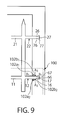
- a mold 100 which has a pair of first auxiliary protrusion portions 102b 1 and 102b 2 for positioning and a pair of second auxiliary protrusion portions 103b 1 and 103b 2 for positioning, in addition to the pair of first protrusion portions 102a 1 and 102a 2 and the pair of second protrusion portions 103a 1 and 103a 2 , is used.
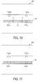
- Lower ends of the pair of first auxiliary protrusion portions 102b 1 and 102b 2 are located below lower ends of the pair of first protrusion portions 102a 1 and 102a 2 (see Figs. 10 and 11 ).
- Lower ends of the pair of second auxiliary protrusion portions 103b 1 and 103b 2 are located below lower ends of the pair of second protrusion portions 103a 1 and 103a 2 (see Figs. 13 and 14 ).
- first auxiliary protrusion portions 102b 1 and 102b 2 and the second auxiliary protrusion portions 103b 1 and 103b 2 respectively have pressed the pair of first clamping portions 62 and the pair of second clamping portions 63
- the pair of first protrusion portions 102a 1 and 102a 2 and the pair of second protrusion portions 103a 1 and 103a 2 respectively press the pair of first clamping portions 62 and the pair of second clamping portions 63.
- a deformation amount of the first clamping portions 62 by the first auxiliary protrusion portions 102b 1 and 102b 2 is smaller than a deformation amount of the first clamping portions 62 by the first protrusion portions 102a 1 and 102a 2 .
- a deformation amount of the first clamping portions 62 by the first protrusion portions 102a 1 and 102a 2 is smaller than a deformation amount of the first clamping portions 62 by the first protrusion portions 102a 1 and 102a 2 .
- a deformation amount of the second clamping portions 63 by the second auxiliary protrusion portions 103b 1 and 103b 2 is smaller than a deformation amount of the second clamping portions 62 by the second protrusion portions 103a 1 and 103a 2 .
- each portion of the pair of first clamping portions 62 is pressed by the pair of first protrusion portions 102a 1 and 102a 2 of the mold 100, and each portion of the pair of second clamping portions 63 is pressed by the pair of second protrusion portions 103a 1 and 103a 2 of the mold 100, the pair of first auxiliary protrusion portions 102b 1 and 102b 2 and the pair of second auxiliary protrusion portions 103b 1 and 103b 2 respectively press the pair of first clamping portions 62 and the pair of second clamping portions 63.
- each portion of the pair of first clamping portions 62 is pressed to be extended by the first auxiliary protrusion portions 102b 1 and 102b 2 so that the first extension portion 12 is positioned with respect to the first clamping portions 62.
- each portion of the pair of second clamping portions 63 is pressed to be extended by the second auxiliary protrusion portions 103b 1 and 103b 2 , so that the second extension portion 13 is positioned with respect to the second clamping portions 63.
- the one metal plate 10 can be positioned with respect to the other metal plate 50.
- shifting of the position of the one metal plate 10 with respect to the other meal plate 50 can be more reliably prevented.
- a site 62b 1 which is pressed by the first auxiliary protrusion portion 102b 1 of the mold 100, in the one clamping portion 62, and a site 62b 2 , which is pressed by the first auxiliary protrusion portion 102b 2 of the mold 100, in the other first clamping portion 62 are located along a straight line in which the terminal 15 is extended, to be opposed to each other (see Figs. 9 and 10 ).
- a force applied to the first extension portion 12 from the one first clamping portion 62 and a force applied to the first extension portion 12 from the other first clamping portion 62 are opposed to each other.
- a force for rotating the first extension portion 12 with respect to the first clamping portions 62 does not work.
- a site 63b 1 which is pressed by the second auxiliary protrusion portion 103b 1 of the mold 100, in the one second clamping portion 63 and a site 63b 2 , which is pressed by the second auxiliary protrusion portion 103b 2 of the mold 100, in the other second clamping portion 63 are located along a straight line in which the terminal 15 is extended, to be opposed to each other (see Figs. 12 and 13 ).
- a force applied to the second extension portion 13 from the one second clamping portion 63 and a force applied to the second extension portion 13 from the other second clamping portion 63 are opposed to each other.
- a force for rotating the second extension portion 13 with respect to the second clamping portions 63 does not work.
- it can be prevented that the first extension portion 12 is rotated with respect to the first clamping portions 62, and that the second extension portion 13 is rotated with respect to the second clamping portions 63.
Landscapes
- Lead Frames For Integrated Circuits (AREA)
- Encapsulation Of And Coatings For Semiconductor Or Solid State Devices (AREA)
- Moulds For Moulding Plastics Or The Like (AREA)
Abstract
Description
- The present invention relates to a lead frame including one metal plate and the other metal plate joined to the one metal plate, a mold used for manufacturing such a lead frame, and a method of manufacturing a lead frame with a mounted component including such a lead frame.
- It has been conventionally known that a mounted component such as a semiconductor device is placed on a lead frame and the mounted component is sealed with a resin (for example, Patent Document 1). The lead frame on which a mounted component is placed has a terminal like a press-fit terminal. The terminal and the mounted component to be sealed with a resin are connected to each other. Conventionally, a terminal and a location on which a mounted component is placed are formed on a single metal plate.
- Patent Document 1:
JP2010-129795A - The inventor of the present invention came up with an idea that one metal plate having a terminal and the other metal plate on which a mounted component is placed are manufactured separately from each other, and the one metal plate and the other metal plate are joined to each other into a single metal plate. However, when two metal plates are joined to each other, there is a problem in that a resin for sealing a mounted component leaks from a joint portion between the two metal plates.
- In view of the above circumstances, the present invention provides a lead frame that can prevent leakage of resin as much as possible, a mold used for manufacturing such a lead frame, and a method of manufacturing a lead frame with a mounted component including such a lead frame.
- A lead frame according to the present invention comprises:
- one metal plate having a terminal; and
- the other metal plate joined to the one metal plate, on which a mounted component is placed;
- wherein:
- the one metal plate includes a first connection portion connected to the terminal, a first extension portion disposed on one end of the first connection portion to extend from the first connection portion in a first direction, and a second extension portion disposed on the other end of the first connection portion to extend from the first connection portion in a second direction containing a component opposite to the first direction;
- the other metal plate includes a pair of first clamping portions configured to clamp the first extension portion, and a pair of second clamping portions configured to clamp the second extension portion;
- each portion of the pair of first clamping portions is pressed to be extended by a mold, which is used for sealing the mounted component with a resin, so that gaps between the first extension portion and the first clamping portions are filled, whereby the resin is prevented from leaking from between the first extension portion and the first clamping portions; and
- each portion of the pair of second clamping portions is pressed to be extended by the mold, so that gaps between the second extension portion and the second clamping portions are filled, whereby the resin is prevented from leaking from between the second extension portion and the second clamping portions.
- In the lead frame according to the present invention,
the first extension portion and the first clamping portions may have first positioning structures configured to position the first extension portion and the first clamping portions with each other; and
the second extension portion and the second clamping portions may have second positioning structures configured to position the second extension portion and the second clamping portions with each other. - In the lead frame according to the present invention,
an end of the first extension portion may be pressed to be extended, so that the first extension portion is positioned with respect to the first clamping portions; and
an end of the second extension portion may be pressed to be extended, so that the second extension portion is positioned with respect to the second clamping portions. - In the lead frame according to the present invention,
the one metal plate may include a second connection portion connected to the terminal, a third extension portion disposed on one end of the second connection portion to extend from the second connection portion in the first direction, and a fourth extension portion disposed on the other end of the second connection portion to extend from the second connection portion in the second direction; and
the other metal plate may include a pair of third clamping portions configured to clamp the third extension portion, and a pair of fourth clamping portions configured to clamp the fourth extension portion. - In the lead frame according to the present invention,
the third extension portion and the third clamping portions may have third positioning structures configured to position the third extension portion and the third clamping portions with each other; and
the fourth extension portion and the fourth clamping portions may have fourth positioning structures configured to position the fourth extension portion and the fourth clamping portions. - In the lead frame according to the present invention,
an end of the third extension portion may be pressed to be extended, so that the third extension portion is positioned with respect to the third clamping portions; and
an end of the fourth extension portion may be pressed to be extended, so that the fourth extension portion is positioned with respect to the fourth clamping portions. - In the lead frame according to the present invention,
a site, which is pressed by the mold, in one first clamping portion and a site, which is pressed by the mold, in the other first clamping portion may be located to be opposed to each other; and
a site, which is pressed by the mold, in one second clamping portion and a site, which is pressed by the mold, in the other second clamping portion may be located to be opposed to each other. - In the lead frame according to the present invention,
each portion of the pair of first clamping portions may be pressed to be extended by the mold at sites different from the sites of the pair of first clamping portions at which the resin is prevented from leaking from between the first extension portion and the first clamping portions, so that the first extension portion is positioned with respect to the first clamping portions; and
each portion of the pair of second clamping portions may be pressed to be extended by the mold at sites different from the sites of the pair of second clamping portions at which the resin is prevented from leaking from between the second extension portion and the second clamping portions, so that the second extension portion is positioned with respect to the second clamping portions. - In the lead frame according to the present invention,
the first direction and the second direction may be perpendicular to a direction in which the terminal is extended. - A mold according to the present invention is a mold used when a resin is provided onto the mounted component on the lead frame described above, the mold comprising:
- a pair of first protrusion portions configured to press each portion of the pair of first clamping portions, for preventing that the resin leaks from between the first extension portion and the first clamping portions; and
- a pair of second protrusion portions configured to press each portion of the pair of second clamping portions, for preventing that the resin leaks from between the second extension portion and the second clamping portions.
- A method of manufacturing a lead frame with a mounted component according to the present invention comprises:
- joining one metal plate and the other metal plate on which a mounted component is placed, with each other, wherein the one plate includes a terminal, a first connection portion connected to the terminal, a first extension portion disposed on one end of the first connection portion to extend from the first connection portion in a first direction, and a second extension portion disposed on the other end of the first connection portion to extend from the first connection portion in a second direction containing a component opposite to the first direction, and the other metal plate includes a pair of first clamping portions configured to clamp the first extension portion, and a pair of second clamping portions configured to clamp the second extension portion; and
- sealing the mounted component with a resin by using a mold;
- wherein:
- in the step of sealing the mounted component with the resin, each portion of the pair of first clamping portions is pressed to be extended by a mold, which is used for sealing the mounted component with the resin, so that gaps between the first extension portion and the first clamping portions are filled, whereby the resin is prevented from leaking from between the first extension portion and the first clamping portions, and
- each portion of the pair of second clamping portions is pressed to be extended by the mold, so that gaps between the second extension portion and the second clamping portions are filled, whereby the resin is prevented from leaking from between the second extension portion and the second clamping portions.
- According to the present invention, each portion of the pair of first clamping portions is pressed to be extended by the mold, which is used for sealing the mounted component with a resin, so that the gaps between the first extension portion and the first clamping portions are filled, whereby the resin supplied into the mold can be prevented from leaking from between the first extension portion and the first clamping portions. In addition, each portion of the pair of second clamping portions is pressed to be extended by the mold, so that the gaps between the second extension portion and the second clamping portions are filled, whereby the resin supplied into the mold can be prevented from leaking from between the second extension portion and the second clamping portions. Therefore, even when the one metal plate and the other metal plate are joined to each other into a single metal plate as in the present invention, the possibility of leaking out of the resin supplied into the mold can be reduced as much as possible.
-
-
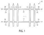
Fig. 1 is a an upper plan view showing one metal plate of a lead frame according to a first embodiment of the present invention. -
Fig. 2 is an upper plan view showing the other metal plate of the lead frame according to the first embodiment of the present invention. -
Fig. 3 is an upper plan view showing that a part of a lead frame with a mounted component according to the first embodiment of the present invention is placed in a mold. -
Figs. 4(a) and 4(b) are enlarged upper plan views showing the lead frame according to the first embodiment of the present invention in which a first extension portion is joined to first clamping portions. -
Fig. 5 is an upper plan view corresponding toFig. 4(a) , showing that a part of the lead frame with a mounted component according to the first embodiment of the present invention is placed in the mold. -
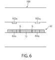
Fig. 6 is a sectional view ofFig. 5 taken along a line A1-A1 ofFig. 5 . -
Fig. 7 is an upper plan view corresponding toFig. 4(b) , showing that a part of the lead frame with a mounted component according to the first embodiment of the present invention is placed in the mold. -
Fig. 8 is a sectional view ofFig. 7 taken along a line A2-A2 ofFig. 7 . -
Fig. 9 is an enlarged upper plan view showing the lead frame according to a second embodiment of the present invention in which a first extension portion is jointed to the first clamping portions, and a part of the lead frame with a mounted component is paled in a mold. -
Fig. 10 is a sectional view ofFig. 9 taken along a line A3-A3 ofFig. 9 . -
Fig. 11 is a sectional view ofFig. 9 taken along a line B1-B1 ofFig. 9 . -
Fig. 12 is an enlarged upper plan view showing the lead frame according to the second embodiment of the present invention in which a second extension portion is jointed to second clamping portions, and a part of the lead frame with a mounted component is paled in a mold. -
Fig. 13 is a sectional view ofFig. 12 taken along a line A4-A4 ofFig. 12 . -
Fig. 14 is a sectional view ofFig. 12 taken along a line B2-B2 ofFig. 12 . - Herebelow, a lead frame, a mold and a method of manufacturing a lead frame with a mounted component in a first embodiment according to the present invention will be described with reference to the drawings.
Figs. 1 to 8 are views for explaining the first embodiment of the present invention. - As shown in
Fig. 3 , a lead frame with a mounted component in this embodiment includes: onemetal plate 10 having a plurality ofterminals 15; and theother metal plate 50 joined to the onemetal plate 10, with a mountedcomponent 91, such as an IC chip, being placed thereon. The onemetal plate 10 is plated as a whole. As shown inFig. 3 , a mountedsubstrate 90 on which the mountedcomponent 91 is placed is disposed on theother metal plate 50. In addition, each terminal 15 of the onemetal plate 10 and the mountedcomponent 91 or a circuit (not shown) on the mountedplate 90 are connected to each other through awire 96. - The
other metal plate 50 is, for example, a copper plate, while the onemetal plate 10 is formed by plating a metal plate made of a phosphorus bronze material. As to a plating for the onemetal plate 10, a distal end side of each terminal 15 (upper side inFig. 1 ) is plated with a first plating such as a tin plating, and the remaining part is plated with a second plating such as nickel plating. To be more specific, plating is firstly carried out by the second plating such as a nickel plating, and the distal side end of the terminal 15 is then plated with the first plating such as a tin plating. - As shown in
Fig. 1 , thefirst metal plate 10 includes afirst connection portion 11 that connects the plurality ofterminals 15 to each other, afirst extension portion 12 disposed on one end of thefirst connection portion 11 to extend from thefirst connection portion 11 in a first direction (right direction inFig. 1 ), and asecond extension portion 13 disposed on the other end of thefirst connection portion 11 to extend from thefirst connection portion 11 in a second direction (left direction inFig. 1 ) containing a component opposite to the first direction. In this embodiment, although description is made on the assumption that the second direction is opposed to the first direction, it should be noted that this is a mere example. In this embodiment, although description is made on the assumption that each of the first direction and the second direction is perpendicular to a direction in which each terminal 15 is extended (up and down direction inFig. 1 ), it should be noted that this is also a mere example. - As shown in
Fig. 2 , theother metal plate 50 includes a firstfitting portion 51 having a pair offirst clamping portions 62 configured to clamp thefirst extension portion 12, and a secondfitting portion 52 having a pair of clampingportions 63 configured to clamp thesecond extension portion 13. In this embodiment, each portion of the pair offirst clamping portions 62 is pressed to be extended by amold 100, which is used for sealing the mountedcomponent 91 with a resin, so that gaps G (seeFig. 6 ) between thefirst extension portion 12 and thefirst clamping portions 62 are filled, whereby the resin is prevented from leaking from between thefirst extension portion 12 and thefirst clamping portions 62. Similarly, each portion of the pair ofsecond clamping portions 63 is pressed to be extended by themold 100, so that gaps G (seeFig. 8 ) between thesecond extension portion 13 and thesecond clamping portions 63 are filled, whereby the resin is prevented from leaking from between thesecond extension portion 13 and thesecond clamping portions 63. - As shown in
Figs. 1 and2 , thefirst extension portion 12 and thefirst clamping portions 62 havefirst positioning structures first extension portion 12 and thefirst clamping portions 62 with each other. Similarly, thesecond extension portion 13 and thesecond clamping portions 63 havesecond positioning structures second extension portion 13 and thesecond clamping portions 63 with each other. To be more specific, as shown inFig. 1 , thefirst extension portion 12 has a firstnarrow portion 16 having a smaller width, and a firstwide portion 17 extended from the firstnarrow portion 16 toward a distal end side and having a larger width than that of the firstnarrow portion 16. In addition, as shown inFig. 2 , the firstfitting portion 51 has a pair offirst projection portions 66 disposed on thefirst clamping portions 62 to correspond to the firstnarrow portion 16, and afirst depression portion 67 corresponding to the firstwide portion 17. The firstnarrow portion 16 is positioned between the pair offirst projection portions 66, so that thefirst extension portion 12 and thefirst clamping portions 62 are positioned with each other. Thesecond extension portion 13 has a secondnarrow portion 18 having a smaller width, and a secondwide portion 19 extended from the secondnarrow portion 18 toward a distal end side and having a larger width than that of the secondnarrow portion 18. In addition, the secondfitting portion 52 has a pair ofsecond projection portions 68 disposed on thesecond clamping portions 63 to correspond to the secondnarrow portion 18 and asecond depression portion 69 corresponding to the secondwide portion 19. The secondnarrow portion 18 is positioned between the pair ofsecond projection portions 68, so that thesecond extension portion 13 and thesecond clamping portions 63 are positioned with each other. - In addition, in this embodiment, an end of the
first extension portion 12, i.e., the firstwide portion 17 is pressed to be extended, so that thefirst extension portion 12 is positioned with respect to the first clamping portions 62 (seeFigs. 1 and2 ). Meanwhile, an end of thesecond extension portion 13, i.e., the secondwide portion 19 is pressed to be extended, so that thesecond extension portion 13 is positioned with respect to thesecond clamping portions 63. To be more specific, the firstwide portion 17 of thefirst extension portion 12 is pressed to be horizontally extended, so that the firstwide portion 17 comes into contact with thefist depression portion 67 of the firstfitting portion 51. Thus, the firstwide portion 17 of thefirst extension portion 12 is caulked to thefirst depression portion 67, so that thefirst extension portion 12 is positioned with respect to thefirst clamping portions 62. Similarly, the secondwide portion 19 of thesecond extension portion 13 is pressed to be horizontally extended, so that the secondwide portion 19 comes into contact with thesecond depression portion 69 of the secondfitting portion 52. Thus, the secondwide portion 19 of thesecond extension portion 13 is caulked to thesecond depression portion 69, so that thesecond extension portion 13 is positioned with respect to thesecond clamping portions 63. - As shown in
Fig. 1 , the onemetal plate 10 in this embodiment includes asecond connection portion 21 connected to theterminals 15, athird extension portion 22 disposed on one end of thesecond connection portion 21 to extend from thesecond connection portion 21 in the first direction (right direction inFig. 1 ), and afourth extension portion 23 disposed on the other end of thesecond connection portion 21 to extend from thesecond connection portion 21 in the second direction. In addition, as shown inFig. 2 , theother metal plate 50 includes a thirdfitting portion 53 having a pair ofthird clamping portions 72 configured to clamp thethird extension portion 22, and a fourthfitting portion 54 having a pair offourth clamping portions 73 configured to clamp thefourth extension portion 23. - As shown in
Figs. 1 and2 , thethird extension portion 22 and thethird clamping portions 72 havethird positioning structures third extension portion 22 and thethird clamping portions 72 with each other. Similarly, thefourth extension portion 23 and thefourth clamping portions 73 havefourth positioning structures fourth extension portion 23 and thefourth clamping portions 73 with each other. To be more specific, as shown inFig. 1 , thethird extension portion 22 has a thirdnarrow portion 26 having a smaller width, and a thirdwide portion 27 extended from the thirdnarrow portion 26 toward a distal end side and having a larger width than that of the thirdnarrow portion 26. In addition, as shown inFig. 2 , the thirdfitting portion 53 has a pair ofthird projection portions 76 disposed on thethird clamping portions 72 to correspond to the thirdnarrow portion 26, and athird depression portion 77 corresponding to the thirdwide portion 27. The thirdnarrow portion 26 is positioned between the pair ofthird projection portions 76, so that thethird extension portion 22 and thethird clamping portions 72 are positioned with each other. Meanwhile, thefourth extension portion 23 has a fourthnarrow portion 28 having a smaller width, and a fourthwide portion 29 extended from the fourthnarrow portion 28 toward a distal end side and having a lager width than that of the fourthnarrow portion 28. The fourthfitting portion 54 has a pair offourth projection portions 78 disposed on thefourth clamping portions 73 to correspond to the fourthnarrow portion 28, and afourth depression portion 79 corresponding to the fourthwide portion 29. The fourthnarrow portion 28 is positioned between the pair offourth projection portions 78, so that thefourth extension portion 23 and thefourth clamping portions 73 are positioned with each other. - In this embodiment, an end of the
third extension portion 22, i.e., so that the thirdwide portion 27 is pressed to be extended, thethird extension portion 22 is positioned with respect to the third clamping portions 72 (seeFigs. 1 and2 ). Meanwhile, an end of thefourth extension portion 23, i.e., the fourthwide portion 29 is pressed to be extended, so that thefourth extension portion 23 is positioned with respect to thefourth clamping portions 73. To be more specific, the thirdwide portion 27 of thethird extension portion 22 is pressed to be horizontally extended, so that the thirdwide portion 27 comes into contact with thethird depression portion 77. Thus, the thirdwide portion 27 of thethird extension portion 22 is caulked to thethird depression portion 77, so that thethird extension portion 22 is positioned with respect to thethird clamping portions 72. Similarly, the fourthwide portion 29 of thefourth extension portion 23 is pressed to be horizontally extended, so that the fourthwide portion 29 comes into contact with thefourth depression portion 79. Thus, the fourthwide portion 29 of thefourth extension portion 23 is caulked to thefourth depression portion 79, so that thefourth extension portion 23 is positioned with respect to thefourth clamping portions 73. - In this embodiment, as shown in
Fig. 4(a) , a site 62a1, which is pressed by themold 100, in onefirst clamping portion 62 and a site 62a2, which is pressed by themold 100, in the other first clamping portion are located along a straight line extending in a direction in which the terminal 15 is extended (on the straight line extending in the up and down direction inFig. 1 ) to be opposed to each other. In addition, as shown inFig. 4(b) , a site 63a1, which is pressed by themold 100, in onesecond clamping portion 63 and a site 63a2, which is pressed by themold 100, in the othersecond clamping portion 63 are located along a straight line extending in a direction in which the terminal 15 is extended (on the straight line extending in the up and down direction inFig. 1 ) to be opposed to each other. - As shown in
Figs. 5 to 8 , themold 100, which is used when a resin is provided onto the mountedcomponent 91 placed on the lead frame in this embodiment, has a pair of first protrusion portions 102a1 and 102a2 configured to press each portion of the pair offirst clamping portions 62 and a pair of second protrusion portions 103a1 and 103a2 configured to press each portion of the pair ofsecond clamping portions 63. To be more specific, as shown inFig. 6 , the predetermined site 62a1 of the onefirst clamping unit 62 is pressed by the one first protrusion portion 102a1, and the predetermined side 62a2 of the other first clampingportion 62 is pressed by the other first protrusion portion 102a2. In addition, as shown inFig. 8 , a predetermined site 63a1 of the onesecond clamping portion 63 is pressed by one second protrusion portion 103a1, and a predetermined site 63a2 of the othersecond clamping portion 63 is pressed by the other second protrusion portion 103a2. - There is explained a method of manufacturing a lead frame with a mounted component including the mounted
component 91 sealed with a resin, with the sue of the onemetal plate 10 and theother metal plate 50. - Firstly, the one
metal plate 10, which is plated as a whole, and theother metal plate 50 are prepared. In this embodiment, at this time, the onemetal plate 10 is plated as a whole, and the mountedsubstrate 90 on which the mountedcomponent 91 is placed is joined to theother metal plate 50. - Then, the
first extension portion 12 is positioned between the pair offirst clamping portions 62, thesecond extension portion 13 is positioned between the pair ofsecond clamping portions 63, thethird extension portion 22 is positioned between the pair ofthird clamping portions 72, and thefourth extension portion 23 is positioned between the pair of fourth clamping portions 73 (seeFigs. 1 and2 ). - Then, the first
wide portion 17 of thefirst extension portion 12 is pressed to be extended so that the firstwide portion 17 is caulked to thefirst depression portion 67, whereby thefirst extension portion 12 is positioned with respect to thefirst clamping portions 62. The secondwide portion 19 of thesecond extension portion 13 is pressed to be extended so that the secondwide portion 19 is caulked to thesecond depression portion 69, whereby thesecond extension portion 13 is positioned with respect to thesecond clamping portions 63. The thirdwide portion 27 of thethird extension portion 22 is pressed to be extended so that the thirdwide portion 27 is caulked to thethird depression portion 77, whereby thethird extension portion 22 is positioned with respect to thethird clamping portions 72. The fourthwide portion 29 of thefourth extension unit 23 is pressed to be extended so that the fourthwide portion 29 is caulked to thefourth depression portion 79, whereby thefourth extension portion 23 is positioned with respect to thefourth clamping portions 73. - In this embodiment, as described above, the
respective extension portions respective clamping portions respective extension portions respective depression portions metal plate 10 is positioned with respect to theother metal plate 50. - Then, the
first extension portion 12 is welded to the firstfitting portion 51 by laser, for example. Thesecond extension portion 13 is welded to the secondfitting portion 52 by laser, for example. Thethird extension portion 22 is welded to the thirdfitting portion 53 by laser, for example. Thefourth extension portion 23 is welded to the fourthfitting portion 54 by laser, for example. As a result, the onemetal plate 10 is joined to theother plate 50. - Then, each of the
terminals 15 of the onemetal plate 10 and the mountedcomponent 91 or a circuit (not shown) on the mountedsubstrate 90 are connected to each other through thewire 96. - Then, the mounted
component 91 on the lead frame is surrounded by the mold 100 (seeFig. 3 ). At this time, the predetermined sites 62a1 and 62a2 of the pair offirst clamping portions 62 is pressed to be extended by the first protrusion portions 102a1 and 102a2 of themold 100, so that the gaps G between thefirst extension portion 12 and thefirst clamping portions 62 are filled (seeFigs. 5 and6 ). Similarly, the predetermined sites 63a1 and 63a2 of the pair ofsecond clamping portions 63 is pressed to be extended by the pair of second protrusion portions 103a1 and 103a2 of themold 100, so that the gaps G between thesecond extension portion 13 and thesecond clamping portions 63 are filled (seeFigs. 7 and8 ). - Then, a resin is supplied into the
mold 100, so that the mountedcomponent 91 is sealed with the resin. At this time, as described above, the predetermined sites 62a1 and 62a2 of the pair offirst clamping portions 62 is pressed to be extended by the pair of first protrusion portions 102a1 and 102a2 of themold 100, so that the gaps G between the first extension portion 12a and thefirst clamping portions 62 are filled. Thus, the supplied resin is prevented from leaking out from between thefirst extension portion 12 and the first clamping portions 62 (seeFigs. 5 and6 ). Similarly, the predetermined sites 63a1 and 63a2 of the pair ofsecond clamping portions 63 is pressed to be extended by the pair of second protrusion potions 103a1 and 103a2 of themold 100, so that the gaps G between thesecond extension portion 13 and thesecond clamping portions 63 are filled. Thus, the supplied resin is prevented from leaking out from between thesecond extension portion 13 and the second clamping portions 63 (seeFigs. 7 and8 ). - Then, the resin supplied into the
mold 100 is cured, whereby the lead frame with a mounted component including the resin-sealedmounted component 91 is completed. After the resin has been cured, themold 100 is removed. - Next, there is explained an effect achieved by the above-structured embodiment, the effect not being yet stated or being particularly important.
- Firstly, there is explained an effect related to the lead frame obtained by joining the one
metal plate 10 and theother metal plate 50 with each other. - In general, an electric conductivity and an elastic modulus are reversely correlated to each other. Namely, a copper material having a high electric conductivity has a low elastic modulus, while a copper material having a high elastic modulus and a spring property has a low electric conductivity. Thus, in a conventional lead frame made of one material, it is difficult to have both a high electric conductivity and a high elastic modulus.
- Therefore, the inventor of the present invention came up with an idea that two kinds of metal plates made of different materials, which are joined to each other by laser welding, is used as a lead frame. The metal plates are plated. However, there is a problem in that, in the case where the plated metal plates are used, when the plated metal plates are reflown (subjected to a reflow soldering), the plating is re-melted. When the plating is re-melted, a base metal may be exposed and/or a metal surface may have irregularities, which invites defective mounting.
- On the other hand, according to this embodiment, the one
metal plate 10 is plated, and the mountedcomponent 91, such as an IC chip, is reflow-soldered to theother metal plate 50. Only theother metal plate 50 is reflown and thus it is not necessary to reheat the one platedmetal plate 10 so as to re-melt the plating. Thus, the re-melting of the plating of the onemetal plate 10 can be avoided, whereby the defective mounting can be prevented from occurring. - In order that the lead frame is plated as a whole, it can be considered that a lead frame wound in a roll is fed out and immersed in a plating liquid such that the lead frame is plated, and that the plated lead frame is wound in a roll again. However, since the lead frame is wound in a roll, the overall lead frame may be bent (coil set occurs) so that defective assemblage during manufacturing steps occurs and/or that size precision of a completed product is deteriorated. On the other hand, according to this embodiment, since only the one
metal plate 10 is plated and theother metal plate 50 is not plated, disadvantage caused by bending can be reduced as much as possible. In addition, since only the onemetal plate 10 is bent, it does not take a lot of time and effort to straighten the bending. - In addition, when the terminal 15, such as a press fit pin, is disposed on a distal end of the lead frame, a strict positioning precision is required for a distal end of the terminal 15. In this case, a more strict size precision is required. In this regard, according to this embodiment, the one
metal plate 10 is positioned with respect to theother plate 50 by various methods described below. Thus, according to this embodiment, a requirement for strict size precision can be satisfied. - In addition, according to this embodiment, each portion of the pair of clamping
portions 62 is pressed to be extended by themold 100, which is used for sealing the mountedcomponent 91 with a resin, so that the gaps G between thefirst extension portion 12 and thefirst clamping portions 62 are filled, whereby the resin supplied into themold 100 is prevented from leaking from between thefirst extension portion 12 and the first clamping portions 62 (seeFigs. 5 and6 ). In addition, each portion of the pair ofsecond clamping portions 63 is pressed to be extended by themold 100, so that the gaps between thesecond extension portion 13 and thesecond clamping portions 63 are filled, whereby the resin supplied into themodel 100 is prevented from leaking from between thesecond extension portion 13 and the second clamping portions 63 (seeFigs. 7 and8 ). Thus, as in this embodiment, even when the one platedmetal plate 10 having theterminals 15 and theother metal plate 50 on which the mountedcomponent 91 is placed are manufactured separately from each other, and the onemetal plate 10 and theother metal plate 50 are joined to each other into a single metal plate, the possibility of leaking out of the resin supplied into themold 100 can be reduced as much as possible. - It is preferable that an amount of extension of the one
first clamping portion 62 and an amount of extension of the other first clampingportion 62 are equal to each other. In addition, it is preferable that an amount of extension of the onesecond clamping portion 63 and an amount of extension of the othersecond clamping portion 63 are equal to each other. This is because, according to this aspect, occurrence of shifting in the direction in which the terminal 15 is extended (up and down direction inFig. 3 ) of the onemetal plate 10 with respect to theother metal plate 50 can be prevented. - In addition, instead of pressing and extending the pair of
first clamping portions 62 and the pair ofsecond clamping portions 63 by themold 100, it can be considered that thefirst extension portion 12 and thesecond extension portion 13 are pressed to be extended by themold 100. However, in this embodiment, the firstwide portion 17 of thefirst extension portion 12 is pressed to be extended to come into contact with thefirst depression portion 67, so that the firstwide portion 17 of thefirst extension portion 12 is caulked to thefirst depression portion 67. Similarly, the secondwide portion 19 of thesecond extension portion 13 is pressed to be extended to come into contact with thesecond depression portion 69, so that the secondwide portion 19 of thesecond extension portion 13 is caulked to thesecond depression portion 69. As a result, the respectivefirst extension portion 12 and thesecond extension portion 13 do not have sufficient thicknesses to be further extended by themold 100. Thus, as in this embodiment, it is preferable that the pair offirst clamping portions 62 and the pair ofsecond clamping portions 63 is pressed to be extended by themold 100. - According to this embodiment, the
first extension portion 12 and thefirst clamping portions 62 have thefirst positioning structures first extension portion 12 and thefirst clamping portion 62 with each other, and thesecond extension portion 13 and thesecond clamping portions 63 have thesecond positioning structures second extension portion 13 and thesecond clamping portions 63 with each other (seeFigs. 1 and2 ). Thus, the onemetal plate 10 can be positioned with respect to theother metal plate 50 at both ends of the onemetal plate 10. - In this embodiment, the first
narrow portion 16 is positioned between the pair offirst projection portions 66, so that thefirst extension portion 12 and thefirst clamping portions 62 are positioned with each other. The secondnarrow portion 18 is positioned between the pair ofsecond projection portions 68, so that thesecond extension portion 13 and thesecond clamping portions 63 are positioned with each other. Thus, the onemetal plate 10 can be positioned with respect to theother metal plate 50 by a simple manner. - In this embodiment, the first
wide portion 17 of thefirst extension portion 12 is pressed to be extended, so that thefirst extension portion 12 is positioned with respect to thefirst clamping portions 62. The secondwide portion 19 of thesecond extension portion 13 is pressed to be extended, so that thesecond extension portion 13 is positioned with respect to thesecond clamping portions 63. Thus, the onemetal plate 10 is more precisely positioned with respect to themetal plate 50 at both ends of the onemetal plate 10. - Further, in this embodiment, the
third extension portion 22 and thethird clamping portions 72 have thethird positioning structures third extension portion 22 and thethird clamping portions 72 with each other, and thefourth extension portion 23 and thefourth clamping portions 73 have thefourth positioning structures fourth extension portion 23 and thefourth clamping portions 73 with each other (seeFigs. 1 and2 ). Thus, since the onemetal plate 10 can be positioned with respect to theother metal plate 50 at four corners of the onemetal plate 10, the precise positioning can be expected. - In addition, the third
narrow portion 26 is positioned between thethird projection portions 76, so that thethird extension portion 22 and thethird clamping portions 72 are positioned with each other, and the fourthnarrow portion 28 is positioned between the pair offourth projection portions 78, so that thefourth extension portion 23 and thefourth clamping portions 73 are positioned with each other. Thus, the onemetal plate 10 can be positioned with respect to theother metal plate 50 in a simple manner. - In this embodiment, the third
wide portion 19 of thethird extension portion 22 is pressed to be extended, so that thethird extension portion 22 is positioned with respect to thethird clamping portions 72. The fourthwide portion 29 of thefourth extension portion 23 is pressed to be extended, so that thefourth extension portion 23 is positioned with respect to thefourth clamping portions 73. Thus, since the onemetal plate 10 can be positioned with respect to theother metal plate 50 at four corners of the onemetal plate 10, further precise positioning can be expected. - In addition, in this embodiment, the site 62a1, which is pressed by the
mold 100, in the onefirst clamping portion 62 and the site 62a2, which is pressed by themold 100, in the other first clampingportion 62 are located along a straight line extending in a direction in which the terminal 15 is extended, to be opposed to each other (seeFig. 4(a) ). Meanwhile, the site 63a1, which is pressed by themold 100, in the onesecond clamping portion 63 and the site 63a2, which is pressed by themold 100, in the othersecond clamping portion 63 are located along a straight line extending in a direction in which the terminal 15 is extended, to be opposed to each other (seeFig. 4(b) ). Thus, when thefirst clamping portions 62 are pressed by themold 100, it can be prevented that thefirst extension portion 12 is rotated with respect to thefirst clamping portions 62. At the same time, when thesecond clamping portions 63 is pressed by themold 100, it can be prevented that thesecond extension portion 13 is rotated with respect to thesecond clamping portions 63. - This point is explained. The site 62a1, which is pressed by the
mold 100, in the onefirst clamping portion 62 and the site 62a2, which is pressed by themold 100, in the other first clampingportion 62 are located along a straight line extending in a direction in which the terminal 15 is extended, to be opposed to each other. Thus, a force applied to thefirst extension portion 12 from the onefirst clamping portion 62 and a force applied to thefirst extension portion 12 from the other first clampingportion 62 are opposed to each other. As a result, a force for rotating thefirst extension portion 12 with respect to thefirst clamping portions 62 does not work. Similarly, the site 63a1, which is pressed by themold 100, in the onesecond clamping portion 63 and the site 63a2, which is pressed by themold 100, in the othersecond clamping portion 63 are located along a straight line extending in a direction in which the terminal 15 is extended, to be opposed to each other. Thus, a force applied to thesecond extension portion 13 from the onesecond clamping portion 63 and a force applied to thesecond extension portion 13 from the othersecond clamping portion 63 are opposed to each other. As a result, a force for rotating thesecond extension portion 13 with respect to thesecond clamping portions 63 does not work. For this reason, when thefirst clamping portions 62 are pressed by themold 100, it can be prevented that thefirst extension portion 12 is rotated with respect to thefirst clamping portions 62. At the same time, when thesecond clamping portions 63 is pressed by themold 100, it can be prevented that thesecond extension portion 13 is rotated with respect to thesecond clamping portions 63. - Next, a second embodiment of the present invention will be described herebelow with reference to
Figs. 9 to 14 . - In the first embodiment, the
first clamping portions 62 and thesecond clamping portions 63 are pressed by using themold 100 having the pair of first protrusion portions 102a1 and 102a2 and the pair of second protrusion portions 103a1 and 103a2. On the other hand, in the second embodiment, amold 100, which has a pair of first auxiliary protrusion portions 102b1 and 102b2 for positioning and a pair of second auxiliary protrusion portions 103b1 and 103b2 for positioning, in addition to the pair of first protrusion portions 102a1 and 102a2 and the pair of second protrusion portions 103a1 and 103a2, is used. Lower ends of the pair of first auxiliary protrusion portions 102b1 and 102b2 are located below lower ends of the pair of first protrusion portions 102a1 and 102a2 (seeFigs. 10 and 11 ). Lower ends of the pair of second auxiliary protrusion portions 103b1 and 103b2 are located below lower ends of the pair of second protrusion portions 103a1 and 103a2 (seeFigs. 13 and 14 ). Thus, after the first auxiliary protrusion portions 102b1 and 102b2 and the second auxiliary protrusion portions 103b1 and 103b2 respectively have pressed the pair offirst clamping portions 62 and the pair ofsecond clamping portions 63, the pair of first protrusion portions 102a1 and 102a2 and the pair of second protrusion portions 103a1 and 103a2 respectively press the pair offirst clamping portions 62 and the pair ofsecond clamping portions 63. - As shown in
Figs. 9 and11 , since a sectional area of the first auxiliary protrusion portions 102b1 and 102b2 is smaller than a sectional area of the first protrusion portions 102a1 and 102a2, a deformation amount of thefirst clamping portions 62 by the first auxiliary protrusion portions 102b1 and 102b2 is smaller than a deformation amount of thefirst clamping portions 62 by the first protrusion portions 102a1 and 102a2. As shown inFigs. 12 and14 , since a sectional area of the second auxiliary protrusion portions 103b1 and 103b2 is smaller than a sectional area of the second protrusion portions 103a1 and 103a2, a deformation amount of thesecond clamping portions 63 by the second auxiliary protrusion portions 103b1 and 103b2 is smaller than a deformation amount of thesecond clamping portions 62 by the second protrusion portions 103a1 and 103a2. - In the second embodiment, other structures are substantially the same as those of the first embodiment. In the second embodiment, the same portions as those of the first embodiment are shown by the same reference numbers, and detailed description thereof is omitted.
- Also in this embodiment, the same effects as that of the first embodiment can be expected. Since these effects are described in detail in the first embodiment, only effects inherent to this embodiment are described.
- According to this embodiment, before each portion of the pair of
first clamping portions 62 is pressed by the pair of first protrusion portions 102a1 and 102a2 of themold 100, and each portion of the pair ofsecond clamping portions 63 is pressed by the pair of second protrusion portions 103a1 and 103a2 of themold 100, the pair of first auxiliary protrusion portions 102b1 and 102b2 and the pair of second auxiliary protrusion portions 103b1 and 103b2 respectively press the pair offirst clamping portions 62 and the pair ofsecond clamping portions 63. Thus, each portion of the pair offirst clamping portions 62 is pressed to be extended by the first auxiliary protrusion portions 102b1 and 102b2 so that thefirst extension portion 12 is positioned with respect to thefirst clamping portions 62. In addition, each portion of the pair ofsecond clamping portions 63 is pressed to be extended by the second auxiliary protrusion portions 103b1 and 103b2, so that thesecond extension portion 13 is positioned with respect to thesecond clamping portions 63. Thus, before thefirst clamping portions 62 and thesecond clamping portions 63 are pressed by the first protrusion portions 102a1 and 102a2 of themold 100 and the second protrusion portions 103a1 and 103a2 of themold 100, the onemetal plate 10 can be positioned with respect to theother metal plate 50. As a result, when theother metal plate 50 is pressed by themold 100, shifting of the position of the onemetal plate 10 with respect to theother meal plate 50 can be more reliably prevented. - A site 62b1, which is pressed by the first auxiliary protrusion portion 102b1 of the
mold 100, in the one clampingportion 62, and a site 62b2, which is pressed by the first auxiliary protrusion portion 102b2 of themold 100, in the other first clampingportion 62 are located along a straight line in which the terminal 15 is extended, to be opposed to each other (seeFigs. 9 and10 ). Thus, a force applied to thefirst extension portion 12 from the onefirst clamping portion 62 and a force applied to thefirst extension portion 12 from the other first clampingportion 62 are opposed to each other. Thus, a force for rotating thefirst extension portion 12 with respect to thefirst clamping portions 62 does not work. A site 63b1, which is pressed by the second auxiliary protrusion portion 103b1 of themold 100, in the onesecond clamping portion 63 and a site 63b2, which is pressed by the second auxiliary protrusion portion 103b2 of themold 100, in the othersecond clamping portion 63 are located along a straight line in which the terminal 15 is extended, to be opposed to each other (seeFigs. 12 and13 ). Thus, a force applied to thesecond extension portion 13 from the onesecond clamping portion 63 and a force applied to thesecond extension portion 13 from the othersecond clamping portion 63 are opposed to each other. Thus, a force for rotating thesecond extension portion 13 with respect to thesecond clamping portions 63 does not work. As a result, it can be prevented that thefirst extension portion 12 is rotated with respect to thefirst clamping portions 62, and that thesecond extension portion 13 is rotated with respect to thesecond clamping portions 63. - Finally, the aforementioned description of the respective embodiments and disclosure of the drawings are mere example for explaining the invention recited in the claims. The invention recited in the claims should not be limited by the aforementioned description of the respective embodiments and disclosure of the drawings.
-
- 10
- One metal plate
- 11
- First connection portion
- 12
- First extension portion
- 13
- Second extension portion
- 15
- Terminal
- 16
- First positioning structure
- 18
- Second positioning structure
- 21
- Second connection portion
- 22
- Third extension portion
- 23
- Fourth extension portion
- 26
- Third positioning structure
- 28
- Fourth positioning structure
- 50
- Other metal plate
- 62
- First clamping portion
- 63
- Second clamping portion
- 66
- First positioning structure
- 68
- Second positioning structure
- 72
- Third clamping portion
- 73
- Fourth clamping portion
- 76
- Third positioning structure
- 78
- Fourth positioning structure
- 91
- Mounted component
- 100
- Mold
- 102a1, 102a2
- First protrusion portion
- 102b1, 102b2
- First auxiliary protrusion portion
- 103a1, 103a2
- Second protrusion portion
- 103b1, 103b2
- Second auxiliary protrusion portion
Claims (11)
- A lead frame comprising:one metal plate having a terminal; andthe other metal plate joined to the one metal plate, on which a mounted component is placed;wherein:the one metal plate includes a first connection portion connected to the terminal, a first extension portion disposed on one end of the first connection portion to extend from the first connection portion in a first direction, and a second extension portion disposed on the other end of the first connection portion to extend from the first connection portion in a second direction containing a component opposite to the first direction;the other metal plate includes a pair of first clamping portions configured to clamp the first extension portion, and a pair of second clamping portions configured to clamp the second extension portion;each portion of the pair of first clamping portions is pressed to be extended by a mold, which is used for sealing the mounted component with a resin, so that gaps between the first extension portion and the first clamping portions are filled, whereby the resin is prevented from leaking from between the first extension portion and the first clamping portions; andeach portion of the pair of second clamping portions is pressed to be extended by the mold, so that gaps between the second extension portion and the second clamping portions are filled, whereby the resin is prevented from leaking from between the second extension portion and the second clamping portions.
- The lead frame according to claim 1, wherein:the first extension portion and the first clamping portions have first positioning structures configured to position the first extension portion and the first clamping portions with each other; andthe second extension portion and the second clamping portions have second positioning structures configured to position the second extension portion and the second clamping portions with each other.
- The lead frame according to claim 1 or 2, wherein:an end of the first extension portion is pressed to be extended, so that the first extension portion is positioned with respect to the first clamping portions; andan end of the second extension portion is pressed to be extended, so that the second extension portion is positioned with respect to the second clamping portions.
- The lead frame according to any one of claims 1 to 3, wherein:the one metal plate includes a second connection portion connected to the terminal, a third extension portion disposed on one end of the second connection portion to extend from the second connection portion in the first direction, and a fourth extension portion disposed on the other end of the second connection portion to extend from the second connection portion in the second direction; andthe other metal plate includes a pair of third clamping portions configured to clamp the third extension portion, and a pair of fourth clamping portions configured to clamp the fourth extension portion.
- The lead frame according to claim 4, wherein:the third extension portion and the third clamping portions have third positioning structures configured to position the third extension portion and the third clamping portions with each other; andthe fourth extension portion and the fourth clamping portions have fourth positioning structures configured to position the fourth extension portion and the fourth clamping portions.
- The lead frame according to claim 4 or 5, wherein:an end of the third extension portion is pressed to be extended, so that the third extension portion is positioned with respect to the third clamping portions; andan end of the fourth extension portion is pressed to be extended, so that the fourth extension portion is positioned with respect to the fourth clamping portions.
- The lead frame according to any one of claims 1 to 6, wherein;
a site, which is pressed by the mold, in one first clamping portion and a site, which is pressed by the mold, in the other first clamping portion are located to be opposed to each other; and
a site, which is pressed by the mold, in one second clamping portion and a site, which is pressed by the mold, in the other second clamping portion are located to be opposed to each other. - The lead frame according to any one of claims 1 to 7, wherein:each portion of the pair of first clamping portions is pressed to be extended by the mold at sites different from the sites of the pair of first clamping portions at which the resin is prevented from leaking from between the first extension portion and the first clamping portions, so that the first extension portion is positioned with respect to the first clamping portions; andeach portion of the pair of second clamping portions is pressed to be extended by the mold at sites different from the sites of the pair of second clamping portions at which the resin is prevented from leaking from between the second extension portion and the second clamping portions, so that the second extension portion is positioned with respect to the second clamping portions.
- The lead frame according to any one of claims 1 to 8, wherein
the first direction and the second direction are perpendicular to a direction in which the terminal is extended. - A mold used when a resin is provided onto the mounted component on the lead frame according to any one of claims 1 to 9, the mold comprising:a pair of first protrusion portions configured to press each portion of the pair of first clamping portions, for preventing that the resin leaks from between the first extension portion and the first clamping portions; anda pair of second protrusion portions configured to press each portion of the pair of second clamping portions, for preventing that the resin leaks from between the second extension portion and the second clamping portions.
- A method of manufacturing a lead frame with a mounted component, comprising:joining one metal plate and the other metal plate on which a mounted component is placed, with each other, wherein the one plate includes a terminal, a first connection portion connected to the terminal, a first extension portion disposed on one end of the first connection portion to extend from the first connection portion in a first direction, and a second extension portion disposed on the other end of the first connection portion to extend from the first connection portion in a second direction containing a component opposite to the first direction, and the other metal plate includes a pair of first clamping portions configured to clamp the first extension portion, and a pair of second clamping portions configured to clamp the second extension portion; andsealing the mounted component with a resin by using a mold;wherein:in the step of sealing the mounted component with the resin, each portion of the pair of first clamping portions is pressed to be extended by a mold, which is used for sealing the mounted component with the resin, so that gaps between the first extension portion and the first clamping portions are filled, whereby the resin is prevented from leaking from between the first extension portion and the first clamping portions, andeach portion of the pair of second clamping portions is pressed to be extended by the mold, so that gaps between the second extension portion and the second clamping portions are filled, whereby the resin is prevented from leaking from between the second extension portion and the second clamping portions.
Applications Claiming Priority (1)
| Application Number | Priority Date | Filing Date | Title |
|---|---|---|---|
| PCT/JP2013/082678 WO2015083263A1 (en) | 2013-12-05 | 2013-12-05 | Lead frame, molding die, and method for manufacturing mounting component-attached lead frame |
Publications (3)
| Publication Number | Publication Date |
|---|---|
| EP3079170A1 true EP3079170A1 (en) | 2016-10-12 |
| EP3079170A4 EP3079170A4 (en) | 2017-08-23 |
| EP3079170B1 EP3079170B1 (en) | 2020-01-22 |
Family
ID=53273056
Family Applications (1)
| Application Number | Title | Priority Date | Filing Date |
|---|---|---|---|
| EP13896193.3A Active EP3079170B1 (en) | 2013-12-05 | 2013-12-05 | Molding die with leadframe, and method of manufacturing a resin sealed electronic component on a lead frame |
Country Status (6)
| Country | Link |
|---|---|
| US (1) | US9601416B2 (en) |
| EP (1) | EP3079170B1 (en) |
| JP (1) | JP5937222B2 (en) |
| KR (1) | KR101564636B1 (en) |
| CN (1) | CN104838494B (en) |
| WO (1) | WO2015083263A1 (en) |
Cited By (1)
| Publication number | Priority date | Publication date | Assignee | Title |
|---|---|---|---|---|
| WO2018096050A1 (en) | 2016-11-23 | 2018-05-31 | Abb Schweiz Ag | Manufacturing of a power semiconductor module |
Families Citing this family (1)
| Publication number | Priority date | Publication date | Assignee | Title |
|---|---|---|---|---|
| WO2022048866A1 (en) | 2020-09-02 | 2022-03-10 | Hitachi Energy Switzerland Ag | Pre-product, method and electronic device |
Family Cites Families (20)
| Publication number | Priority date | Publication date | Assignee | Title |
|---|---|---|---|---|
| JPH07114213B2 (en) * | 1988-09-29 | 1995-12-06 | 松下電子工業株式会社 | Lead frame for semiconductor device |
| JP3262823B2 (en) * | 1992-01-08 | 2002-03-04 | アピックヤマダ株式会社 | Lead frame resin mold |
| JP3088193B2 (en) * | 1992-06-05 | 2000-09-18 | 三菱電機株式会社 | Method for manufacturing semiconductor device having LOC structure and lead frame used therein |
| JPH06216178A (en) * | 1993-01-20 | 1994-08-05 | Fujitsu Miyagi Electron:Kk | Molding die for resin-sealed semiconductor device |
| US5977613A (en) * | 1996-03-07 | 1999-11-02 | Matsushita Electronics Corporation | Electronic component, method for making the same, and lead frame and mold assembly for use therein |
| JPH09260568A (en) * | 1996-03-27 | 1997-10-03 | Mitsubishi Electric Corp | Semiconductor device and manufacturing method thereof |
| KR100355796B1 (en) * | 1999-10-15 | 2002-10-19 | 앰코 테크놀로지 코리아 주식회사 | structure of leadframe for semiconductor package and mold for molding the same |
| JP2001217271A (en) * | 2000-02-02 | 2001-08-10 | Matsushita Electric Ind Co Ltd | Resin-sealed mold and method of manufacturing resin-sealed semiconductor device using the same |
| JP3833464B2 (en) * | 2000-11-01 | 2006-10-11 | 株式会社三井ハイテック | Lead frame |
| JP4283514B2 (en) * | 2002-09-24 | 2009-06-24 | 株式会社日立製作所 | Electronic circuit equipment |
| JP2005228815A (en) * | 2004-02-10 | 2005-08-25 | Himeji Toshiba Ep Corp | Lead frame, manufacturing method thereof, and electronic component using the same |
| JP4628996B2 (en) * | 2006-06-01 | 2011-02-09 | 新光電気工業株式会社 | Lead frame, manufacturing method thereof, and semiconductor device |
| JP5004601B2 (en) | 2007-01-22 | 2012-08-22 | パナソニック株式会社 | Package component manufacturing method and semiconductor device manufacturing method |
| JP5089184B2 (en) * | 2007-01-30 | 2012-12-05 | ローム株式会社 | Resin-sealed semiconductor device and manufacturing method thereof |
| JP4563426B2 (en) * | 2007-07-20 | 2010-10-13 | ルネサスエレクトロニクス株式会社 | Resin mold |
| US20090057855A1 (en) * | 2007-08-30 | 2009-03-05 | Maria Clemens Quinones | Semiconductor die package including stand off structures |
| JP4634498B2 (en) | 2008-11-28 | 2011-02-16 | 三菱電機株式会社 | Power semiconductor module |
| JP5793295B2 (en) * | 2010-12-16 | 2015-10-14 | 新電元工業株式会社 | Semiconductor device |
| JP5703008B2 (en) * | 2010-12-16 | 2015-04-15 | 新電元工業株式会社 | Frame assembly, semiconductor device and manufacturing method thereof |
| TW201251140A (en) * | 2011-01-31 | 2012-12-16 | Cree Inc | High brightness light emitting diode (LED) packages, systems and methods with improved resin filling and high adhesion |
-
2013
- 2013-12-05 JP JP2014537399A patent/JP5937222B2/en active Active
- 2013-12-05 US US14/442,721 patent/US9601416B2/en active Active
- 2013-12-05 EP EP13896193.3A patent/EP3079170B1/en active Active
- 2013-12-05 CN CN201380016975.7A patent/CN104838494B/en active Active
- 2013-12-05 WO PCT/JP2013/082678 patent/WO2015083263A1/en not_active Ceased
- 2013-12-05 KR KR1020147024972A patent/KR101564636B1/en active Active
Cited By (2)
| Publication number | Priority date | Publication date | Assignee | Title |
|---|---|---|---|---|
| WO2018096050A1 (en) | 2016-11-23 | 2018-05-31 | Abb Schweiz Ag | Manufacturing of a power semiconductor module |
| US11189556B2 (en) | 2016-11-23 | 2021-11-30 | Abb Power Grids Switzerland Ag | Manufacturing of a power semiconductor module |
Also Published As
| Publication number | Publication date |
|---|---|
| EP3079170A4 (en) | 2017-08-23 |
| EP3079170B1 (en) | 2020-01-22 |
| KR101564636B1 (en) | 2015-10-30 |
| CN104838494B (en) | 2017-06-23 |
| WO2015083263A1 (en) | 2015-06-11 |
| KR20150080447A (en) | 2015-07-09 |
| US20160293525A1 (en) | 2016-10-06 |
| CN104838494A (en) | 2015-08-12 |
| US9601416B2 (en) | 2017-03-21 |
| JP5937222B2 (en) | 2016-06-22 |
| JPWO2015083263A1 (en) | 2017-03-16 |
Similar Documents
| Publication | Publication Date | Title |
|---|---|---|
| JP7173487B2 (en) | semiconductor equipment | |
| JP5125975B2 (en) | Resin case manufacturing method | |
| CN101452765A (en) | Solid electrolytic capacitor | |
| JP5041996B2 (en) | Solid electrolytic capacitor | |
| US20090179315A1 (en) | Semiconductor Die Packages Having Solder-free Connections, Systems Using the Same, and Methods of Making the Same | |
| EP3079170B1 (en) | Molding die with leadframe, and method of manufacturing a resin sealed electronic component on a lead frame | |
| US20020022304A1 (en) | Semiconductor device, method for fabricating the same, circuit board and electronic device | |
| JP3776907B2 (en) | Circuit board | |
| US20190348404A1 (en) | Method of manufacturing power semiconductor device and power semiconductor device | |
| CN101553908B (en) | Folded frame carrier for MOSFET BGA | |
| JP6189222B2 (en) | Lead frame and lead frame manufacturing method | |
| US9252086B2 (en) | Connector and resin-sealed semiconductor device | |
| US20220301987A1 (en) | Semiconductor device | |
| JP5370536B2 (en) | Solid electrolytic capacitor | |
| TWI274357B (en) | Method for cutting lead terminal of packaged electronic component | |
| JPH08148623A (en) | Semiconductor device | |
| JP2014049584A (en) | Lead frame and manufacturing method of resin-sealed semiconductor device | |
| JP5165302B2 (en) | Semiconductor device and manufacturing method thereof | |
| JPH11297729A (en) | Semiconductor package and method of forming the same | |
| US20230328892A1 (en) | Micro solder joint and stencil aperture design | |
| JP6352508B2 (en) | Lead frame and lead frame manufacturing method | |
| JP4735352B2 (en) | Electronic component arrangement structure and arrangement method | |
| CN114038823A (en) | Diode packaging structure and packaging process thereof | |
| JP5370535B2 (en) | Solid electrolytic capacitor | |
| JP2005322568A (en) | Connection method of terminal and circuit board |
Legal Events
| Date | Code | Title | Description |
|---|---|---|---|
| PUAI | Public reference made under article 153(3) epc to a published international application that has entered the european phase |
Free format text: ORIGINAL CODE: 0009012 |
|
| 17P | Request for examination filed |
Effective date: 20150507 |
|
| AK | Designated contracting states |
Kind code of ref document: A1 Designated state(s): AL AT BE BG CH CY CZ DE DK EE ES FI FR GB GR HR HU IE IS IT LI LT LU LV MC MK MT NL NO PL PT RO RS SE SI SK SM TR |
|
| AX | Request for extension of the european patent |
Extension state: BA ME |
|
| DAX | Request for extension of the european patent (deleted) | ||
| A4 | Supplementary search report drawn up and despatched |
Effective date: 20170720 |
|
| RIC1 | Information provided on ipc code assigned before grant |
Ipc: H01L 23/48 20060101AFI20170714BHEP Ipc: H01L 21/56 20060101ALI20170714BHEP Ipc: H01L 23/495 20060101ALI20170714BHEP |
|
| REG | Reference to a national code |
Ref country code: DE Ref legal event code: R079 Ref document number: 602013065407 Country of ref document: DE Free format text: PREVIOUS MAIN CLASS: H01L0023480000 Ipc: H01L0023310000 |
|
| RIC1 | Information provided on ipc code assigned before grant |
Ipc: H01L 23/31 20060101AFI20190503BHEP Ipc: H01L 21/56 20060101ALI20190503BHEP Ipc: H01L 23/495 20060101ALI20190503BHEP |
|
| GRAP | Despatch of communication of intention to grant a patent |
Free format text: ORIGINAL CODE: EPIDOSNIGR1 |
|
| STAA | Information on the status of an ep patent application or granted ep patent |
Free format text: STATUS: GRANT OF PATENT IS INTENDED |
|
| INTG | Intention to grant announced |
Effective date: 20190701 |
|
| GRAS | Grant fee paid |
Free format text: ORIGINAL CODE: EPIDOSNIGR3 |
|
| GRAA | (expected) grant |
Free format text: ORIGINAL CODE: 0009210 |
|
| STAA | Information on the status of an ep patent application or granted ep patent |
Free format text: STATUS: THE PATENT HAS BEEN GRANTED |
|
| AK | Designated contracting states |
Kind code of ref document: B1 Designated state(s): AL AT BE BG CH CY CZ DE DK EE ES FI FR GB GR HR HU IE IS IT LI LT LU LV MC MK MT NL NO PL PT RO RS SE SI SK SM TR |
|
| REG | Reference to a national code |
Ref country code: GB Ref legal event code: FG4D |
|
| REG | Reference to a national code |
Ref country code: CH Ref legal event code: EP |
|
| REG | Reference to a national code |
Ref country code: AT Ref legal event code: REF Ref document number: 1227474 Country of ref document: AT Kind code of ref document: T Effective date: 20200215 |
|
| REG | Reference to a national code |
Ref country code: IE Ref legal event code: FG4D |
|
| REG | Reference to a national code |
Ref country code: DE Ref legal event code: R096 Ref document number: 602013065407 Country of ref document: DE |
|
| REG | Reference to a national code |
Ref country code: NL Ref legal event code: MP Effective date: 20200122 |
|
| REG | Reference to a national code |
Ref country code: LT Ref legal event code: MG4D |
|
| PG25 | Lapsed in a contracting state [announced via postgrant information from national office to epo] |
Ref country code: RS Free format text: LAPSE BECAUSE OF FAILURE TO SUBMIT A TRANSLATION OF THE DESCRIPTION OR TO PAY THE FEE WITHIN THE PRESCRIBED TIME-LIMIT Effective date: 20200122 Ref country code: NL Free format text: LAPSE BECAUSE OF FAILURE TO SUBMIT A TRANSLATION OF THE DESCRIPTION OR TO PAY THE FEE WITHIN THE PRESCRIBED TIME-LIMIT Effective date: 20200122 Ref country code: NO Free format text: LAPSE BECAUSE OF FAILURE TO SUBMIT A TRANSLATION OF THE DESCRIPTION OR TO PAY THE FEE WITHIN THE PRESCRIBED TIME-LIMIT Effective date: 20200422 Ref country code: FI Free format text: LAPSE BECAUSE OF FAILURE TO SUBMIT A TRANSLATION OF THE DESCRIPTION OR TO PAY THE FEE WITHIN THE PRESCRIBED TIME-LIMIT Effective date: 20200122 Ref country code: PT Free format text: LAPSE BECAUSE OF FAILURE TO SUBMIT A TRANSLATION OF THE DESCRIPTION OR TO PAY THE FEE WITHIN THE PRESCRIBED TIME-LIMIT Effective date: 20200614 |
|
| PG25 | Lapsed in a contracting state [announced via postgrant information from national office to epo] |
Ref country code: BG Free format text: LAPSE BECAUSE OF FAILURE TO SUBMIT A TRANSLATION OF THE DESCRIPTION OR TO PAY THE FEE WITHIN THE PRESCRIBED TIME-LIMIT Effective date: 20200422 Ref country code: LV Free format text: LAPSE BECAUSE OF FAILURE TO SUBMIT A TRANSLATION OF THE DESCRIPTION OR TO PAY THE FEE WITHIN THE PRESCRIBED TIME-LIMIT Effective date: 20200122 Ref country code: SE Free format text: LAPSE BECAUSE OF FAILURE TO SUBMIT A TRANSLATION OF THE DESCRIPTION OR TO PAY THE FEE WITHIN THE PRESCRIBED TIME-LIMIT Effective date: 20200122 Ref country code: HR Free format text: LAPSE BECAUSE OF FAILURE TO SUBMIT A TRANSLATION OF THE DESCRIPTION OR TO PAY THE FEE WITHIN THE PRESCRIBED TIME-LIMIT Effective date: 20200122 Ref country code: GR Free format text: LAPSE BECAUSE OF FAILURE TO SUBMIT A TRANSLATION OF THE DESCRIPTION OR TO PAY THE FEE WITHIN THE PRESCRIBED TIME-LIMIT Effective date: 20200423 Ref country code: IS Free format text: LAPSE BECAUSE OF FAILURE TO SUBMIT A TRANSLATION OF THE DESCRIPTION OR TO PAY THE FEE WITHIN THE PRESCRIBED TIME-LIMIT Effective date: 20200522 |
|
| REG | Reference to a national code |
Ref country code: DE Ref legal event code: R097 Ref document number: 602013065407 Country of ref document: DE |
|
| PG25 | Lapsed in a contracting state [announced via postgrant information from national office to epo] |
Ref country code: SK Free format text: LAPSE BECAUSE OF FAILURE TO SUBMIT A TRANSLATION OF THE DESCRIPTION OR TO PAY THE FEE WITHIN THE PRESCRIBED TIME-LIMIT Effective date: 20200122 Ref country code: CZ Free format text: LAPSE BECAUSE OF FAILURE TO SUBMIT A TRANSLATION OF THE DESCRIPTION OR TO PAY THE FEE WITHIN THE PRESCRIBED TIME-LIMIT Effective date: 20200122 Ref country code: LT Free format text: LAPSE BECAUSE OF FAILURE TO SUBMIT A TRANSLATION OF THE DESCRIPTION OR TO PAY THE FEE WITHIN THE PRESCRIBED TIME-LIMIT Effective date: 20200122 Ref country code: RO Free format text: LAPSE BECAUSE OF FAILURE TO SUBMIT A TRANSLATION OF THE DESCRIPTION OR TO PAY THE FEE WITHIN THE PRESCRIBED TIME-LIMIT Effective date: 20200122 Ref country code: ES Free format text: LAPSE BECAUSE OF FAILURE TO SUBMIT A TRANSLATION OF THE DESCRIPTION OR TO PAY THE FEE WITHIN THE PRESCRIBED TIME-LIMIT Effective date: 20200122 Ref country code: EE Free format text: LAPSE BECAUSE OF FAILURE TO SUBMIT A TRANSLATION OF THE DESCRIPTION OR TO PAY THE FEE WITHIN THE PRESCRIBED TIME-LIMIT Effective date: 20200122 Ref country code: SM Free format text: LAPSE BECAUSE OF FAILURE TO SUBMIT A TRANSLATION OF THE DESCRIPTION OR TO PAY THE FEE WITHIN THE PRESCRIBED TIME-LIMIT Effective date: 20200122 Ref country code: DK Free format text: LAPSE BECAUSE OF FAILURE TO SUBMIT A TRANSLATION OF THE DESCRIPTION OR TO PAY THE FEE WITHIN THE PRESCRIBED TIME-LIMIT Effective date: 20200122 |
|
| REG | Reference to a national code |
Ref country code: AT Ref legal event code: MK05 Ref document number: 1227474 Country of ref document: AT Kind code of ref document: T Effective date: 20200122 |
|
| PLBE | No opposition filed within time limit |
Free format text: ORIGINAL CODE: 0009261 |
|
| STAA | Information on the status of an ep patent application or granted ep patent |
Free format text: STATUS: NO OPPOSITION FILED WITHIN TIME LIMIT |
|
| 26N | No opposition filed |
Effective date: 20201023 |
|
| PG25 | Lapsed in a contracting state [announced via postgrant information from national office to epo] |
Ref country code: AT Free format text: LAPSE BECAUSE OF FAILURE TO SUBMIT A TRANSLATION OF THE DESCRIPTION OR TO PAY THE FEE WITHIN THE PRESCRIBED TIME-LIMIT Effective date: 20200122 Ref country code: IT Free format text: LAPSE BECAUSE OF FAILURE TO SUBMIT A TRANSLATION OF THE DESCRIPTION OR TO PAY THE FEE WITHIN THE PRESCRIBED TIME-LIMIT Effective date: 20200122 |
|
| PG25 | Lapsed in a contracting state [announced via postgrant information from national office to epo] |
Ref country code: PL Free format text: LAPSE BECAUSE OF FAILURE TO SUBMIT A TRANSLATION OF THE DESCRIPTION OR TO PAY THE FEE WITHIN THE PRESCRIBED TIME-LIMIT Effective date: 20200122 Ref country code: SI Free format text: LAPSE BECAUSE OF FAILURE TO SUBMIT A TRANSLATION OF THE DESCRIPTION OR TO PAY THE FEE WITHIN THE PRESCRIBED TIME-LIMIT Effective date: 20200122 |
|
| REG | Reference to a national code |
Ref country code: CH Ref legal event code: PL |
|
| PG25 | Lapsed in a contracting state [announced via postgrant information from national office to epo] |
Ref country code: MC Free format text: LAPSE BECAUSE OF FAILURE TO SUBMIT A TRANSLATION OF THE DESCRIPTION OR TO PAY THE FEE WITHIN THE PRESCRIBED TIME-LIMIT Effective date: 20200122 |
|
| REG | Reference to a national code |
Ref country code: BE Ref legal event code: MM Effective date: 20201231 |
|
| PG25 | Lapsed in a contracting state [announced via postgrant information from national office to epo] |
Ref country code: IE Free format text: LAPSE BECAUSE OF NON-PAYMENT OF DUE FEES Effective date: 20201205 Ref country code: LU Free format text: LAPSE BECAUSE OF NON-PAYMENT OF DUE FEES Effective date: 20201205 Ref country code: FR Free format text: LAPSE BECAUSE OF NON-PAYMENT OF DUE FEES Effective date: 20201231 |
|
| PG25 | Lapsed in a contracting state [announced via postgrant information from national office to epo] |
Ref country code: LI Free format text: LAPSE BECAUSE OF NON-PAYMENT OF DUE FEES Effective date: 20201231 Ref country code: CH Free format text: LAPSE BECAUSE OF NON-PAYMENT OF DUE FEES Effective date: 20201231 |
|
| PG25 | Lapsed in a contracting state [announced via postgrant information from national office to epo] |
Ref country code: TR Free format text: LAPSE BECAUSE OF FAILURE TO SUBMIT A TRANSLATION OF THE DESCRIPTION OR TO PAY THE FEE WITHIN THE PRESCRIBED TIME-LIMIT Effective date: 20200122 Ref country code: MT Free format text: LAPSE BECAUSE OF FAILURE TO SUBMIT A TRANSLATION OF THE DESCRIPTION OR TO PAY THE FEE WITHIN THE PRESCRIBED TIME-LIMIT Effective date: 20200122 Ref country code: CY Free format text: LAPSE BECAUSE OF FAILURE TO SUBMIT A TRANSLATION OF THE DESCRIPTION OR TO PAY THE FEE WITHIN THE PRESCRIBED TIME-LIMIT Effective date: 20200122 |
|
| PG25 | Lapsed in a contracting state [announced via postgrant information from national office to epo] |
Ref country code: MK Free format text: LAPSE BECAUSE OF FAILURE TO SUBMIT A TRANSLATION OF THE DESCRIPTION OR TO PAY THE FEE WITHIN THE PRESCRIBED TIME-LIMIT Effective date: 20200122 Ref country code: AL Free format text: LAPSE BECAUSE OF FAILURE TO SUBMIT A TRANSLATION OF THE DESCRIPTION OR TO PAY THE FEE WITHIN THE PRESCRIBED TIME-LIMIT Effective date: 20200122 |
|
| PG25 | Lapsed in a contracting state [announced via postgrant information from national office to epo] |
Ref country code: BE Free format text: LAPSE BECAUSE OF NON-PAYMENT OF DUE FEES Effective date: 20201231 |
|
| REG | Reference to a national code |
Ref country code: DE Ref legal event code: R079 Ref document number: 602013065407 Country of ref document: DE Free format text: PREVIOUS MAIN CLASS: H01L0023310000 Ipc: H10W0074100000 |
|
| PGFP | Annual fee paid to national office [announced via postgrant information from national office to epo] |
Ref country code: DE Payment date: 20251211 Year of fee payment: 13 |
|
| PGFP | Annual fee paid to national office [announced via postgrant information from national office to epo] |
Ref country code: GB Payment date: 20251219 Year of fee payment: 13 |