EP3079016A2 - Steuerungsvorrichtung zur steuerung mindestens eines manipulators eines projektionsobjektivs - Google Patents
Steuerungsvorrichtung zur steuerung mindestens eines manipulators eines projektionsobjektivs Download PDFInfo
- Publication number
- EP3079016A2 EP3079016A2 EP16000776.1A EP16000776A EP3079016A2 EP 3079016 A2 EP3079016 A2 EP 3079016A2 EP 16000776 A EP16000776 A EP 16000776A EP 3079016 A2 EP3079016 A2 EP 3079016A2
- Authority
- EP
- European Patent Office
- Prior art keywords
- powers
- travel
- control device
- manipulator
- optical element
- Prior art date
- Legal status (The legal status is an assumption and is not a legal conclusion. Google has not performed a legal analysis and makes no representation as to the accuracy of the status listed.)
- Granted
Links
Images

Classifications
-
- G—PHYSICS
- G03—PHOTOGRAPHY; CINEMATOGRAPHY; ANALOGOUS TECHNIQUES USING WAVES OTHER THAN OPTICAL WAVES; ELECTROGRAPHY; HOLOGRAPHY
- G03F—PHOTOMECHANICAL PRODUCTION OF TEXTURED OR PATTERNED SURFACES, e.g. FOR PRINTING, FOR PROCESSING OF SEMICONDUCTOR DEVICES; MATERIALS THEREFOR; ORIGINALS THEREFOR; APPARATUS SPECIALLY ADAPTED THEREFOR
- G03F7/00—Photomechanical, e.g. photolithographic, production of textured or patterned surfaces, e.g. printing surfaces; Materials therefor, e.g. comprising photoresists; Apparatus specially adapted therefor
- G03F7/70—Microphotolithographic exposure; Apparatus therefor
- G03F7/70216—Mask projection systems
- G03F7/70258—Projection system adjustments, e.g. adjustments during exposure or alignment during assembly of projection system
-
- G—PHYSICS
- G03—PHOTOGRAPHY; CINEMATOGRAPHY; ANALOGOUS TECHNIQUES USING WAVES OTHER THAN OPTICAL WAVES; ELECTROGRAPHY; HOLOGRAPHY
- G03F—PHOTOMECHANICAL PRODUCTION OF TEXTURED OR PATTERNED SURFACES, e.g. FOR PRINTING, FOR PROCESSING OF SEMICONDUCTOR DEVICES; MATERIALS THEREFOR; ORIGINALS THEREFOR; APPARATUS SPECIALLY ADAPTED THEREFOR
- G03F7/00—Photomechanical, e.g. photolithographic, production of textured or patterned surfaces, e.g. printing surfaces; Materials therefor, e.g. comprising photoresists; Apparatus specially adapted therefor
- G03F7/70—Microphotolithographic exposure; Apparatus therefor
- G03F7/70216—Mask projection systems
- G03F7/70258—Projection system adjustments, e.g. adjustments during exposure or alignment during assembly of projection system
- G03F7/70266—Adaptive optics, e.g. deformable optical elements for wavefront control, e.g. for aberration adjustment or correction
-
- G—PHYSICS
- G02—OPTICS
- G02B—OPTICAL ELEMENTS, SYSTEMS OR APPARATUS
- G02B27/00—Optical systems or apparatus not provided for by any of the groups G02B1/00 - G02B26/00, G02B30/00
- G02B27/0012—Optical design, e.g. procedures, algorithms, optimisation routines
-
- G—PHYSICS
- G02—OPTICS
- G02B—OPTICAL ELEMENTS, SYSTEMS OR APPARATUS
- G02B27/00—Optical systems or apparatus not provided for by any of the groups G02B1/00 - G02B26/00, G02B30/00
- G02B27/0025—Optical systems or apparatus not provided for by any of the groups G02B1/00 - G02B26/00, G02B30/00 for optical correction, e.g. distorsion, aberration
- G02B27/0068—Optical systems or apparatus not provided for by any of the groups G02B1/00 - G02B26/00, G02B30/00 for optical correction, e.g. distorsion, aberration having means for controlling the degree of correction, e.g. using phase modulators, movable elements
-
- G—PHYSICS
- G02—OPTICS
- G02B—OPTICAL ELEMENTS, SYSTEMS OR APPARATUS
- G02B7/00—Mountings, adjusting means, or light-tight connections, for optical elements
- G02B7/02—Mountings, adjusting means, or light-tight connections, for optical elements for lenses
- G02B7/023—Mountings, adjusting means, or light-tight connections, for optical elements for lenses permitting adjustment
-
- G—PHYSICS
- G03—PHOTOGRAPHY; CINEMATOGRAPHY; ANALOGOUS TECHNIQUES USING WAVES OTHER THAN OPTICAL WAVES; ELECTROGRAPHY; HOLOGRAPHY
- G03F—PHOTOMECHANICAL PRODUCTION OF TEXTURED OR PATTERNED SURFACES, e.g. FOR PRINTING, FOR PROCESSING OF SEMICONDUCTOR DEVICES; MATERIALS THEREFOR; ORIGINALS THEREFOR; APPARATUS SPECIALLY ADAPTED THEREFOR
- G03F7/00—Photomechanical, e.g. photolithographic, production of textured or patterned surfaces, e.g. printing surfaces; Materials therefor, e.g. comprising photoresists; Apparatus specially adapted therefor
- G03F7/70—Microphotolithographic exposure; Apparatus therefor
- G03F7/70058—Mask illumination systems
- G03F7/70141—Illumination system adjustment, e.g. adjustments during exposure or alignment during assembly of illumination system
-
- G—PHYSICS
- G03—PHOTOGRAPHY; CINEMATOGRAPHY; ANALOGOUS TECHNIQUES USING WAVES OTHER THAN OPTICAL WAVES; ELECTROGRAPHY; HOLOGRAPHY
- G03F—PHOTOMECHANICAL PRODUCTION OF TEXTURED OR PATTERNED SURFACES, e.g. FOR PRINTING, FOR PROCESSING OF SEMICONDUCTOR DEVICES; MATERIALS THEREFOR; ORIGINALS THEREFOR; APPARATUS SPECIALLY ADAPTED THEREFOR
- G03F7/00—Photomechanical, e.g. photolithographic, production of textured or patterned surfaces, e.g. printing surfaces; Materials therefor, e.g. comprising photoresists; Apparatus specially adapted therefor
- G03F7/70—Microphotolithographic exposure; Apparatus therefor
- G03F7/70425—Imaging strategies, e.g. for increasing throughput or resolution, printing product fields larger than the image field or compensating lithography- or non-lithography errors, e.g. proximity correction, mix-and-match, stitching or double patterning
-
- G—PHYSICS
- G03—PHOTOGRAPHY; CINEMATOGRAPHY; ANALOGOUS TECHNIQUES USING WAVES OTHER THAN OPTICAL WAVES; ELECTROGRAPHY; HOLOGRAPHY
- G03F—PHOTOMECHANICAL PRODUCTION OF TEXTURED OR PATTERNED SURFACES, e.g. FOR PRINTING, FOR PROCESSING OF SEMICONDUCTOR DEVICES; MATERIALS THEREFOR; ORIGINALS THEREFOR; APPARATUS SPECIALLY ADAPTED THEREFOR
- G03F7/00—Photomechanical, e.g. photolithographic, production of textured or patterned surfaces, e.g. printing surfaces; Materials therefor, e.g. comprising photoresists; Apparatus specially adapted therefor
- G03F7/70—Microphotolithographic exposure; Apparatus therefor
- G03F7/70425—Imaging strategies, e.g. for increasing throughput or resolution, printing product fields larger than the image field or compensating lithography- or non-lithography errors, e.g. proximity correction, mix-and-match, stitching or double patterning
- G03F7/70433—Layout for increasing efficiency or for compensating imaging errors, e.g. layout of exposure fields for reducing focus errors; Use of mask features for increasing efficiency or for compensating imaging errors
-
- G—PHYSICS
- G03—PHOTOGRAPHY; CINEMATOGRAPHY; ANALOGOUS TECHNIQUES USING WAVES OTHER THAN OPTICAL WAVES; ELECTROGRAPHY; HOLOGRAPHY
- G03F—PHOTOMECHANICAL PRODUCTION OF TEXTURED OR PATTERNED SURFACES, e.g. FOR PRINTING, FOR PROCESSING OF SEMICONDUCTOR DEVICES; MATERIALS THEREFOR; ORIGINALS THEREFOR; APPARATUS SPECIALLY ADAPTED THEREFOR
- G03F7/00—Photomechanical, e.g. photolithographic, production of textured or patterned surfaces, e.g. printing surfaces; Materials therefor, e.g. comprising photoresists; Apparatus specially adapted therefor
- G03F7/70—Microphotolithographic exposure; Apparatus therefor
- G03F7/70483—Information management; Active and passive control; Testing; Wafer monitoring, e.g. pattern monitoring
- G03F7/70491—Information management, e.g. software; Active and passive control, e.g. details of controlling exposure processes or exposure tool monitoring processes
- G03F7/705—Modelling or simulating from physical phenomena up to complete wafer processes or whole workflow in wafer productions
Definitions
- the invention relates to a control device and a method for controlling at least one manipulator of a projection objective for microlithography. Furthermore, the invention relates to a Justierstrom for adjusting a projection lens for microlithography and a projection exposure system for microlithography, each with such a control device.
- a microlithographic projection exposure apparatus is used to produce structures on a substrate in the form of a semiconductor wafer in the production of semiconductor components.
- the projection exposure apparatus comprises a projection objective having a plurality of optical elements for imaging mask structures onto the wafer during an exposure process.
- a projection objective with the least possible wavefront aberrations is required.
- Projection objectives are therefore equipped with manipulators that make it possible to correct wavefront errors by changing the state of individual optical elements of the projection objective. Examples of such a state change include: a change in position in one or a plurality of the six rigid body degrees of freedom of the optical element in question, an exposure of the optical element to heat and / or cold, a deformation of the optical element or a material removal on an optical element by means of a post-processing device.
- a post-processing device is understood as a manipulator of the projection lens in the general sense.
- manipulator modification model The calculation of manipulator changes to be carried out for the correction of an aberration characteristic of a projection objective takes place by means of a position-path-generating optimization algorithm, which is also called "manipulator modification model".
- manipulator modification model Such optimization algorithms are, for example, in WO 2010/034674 A1 described.
- optimization algorithms known from the prior art can be configured to solve the following optimization problem: min ⁇ Mx - b mess ⁇ 2 2 With NB : F i x ⁇ spec x i
- Such an optimization problem is configured by ⁇ Mx - b mess ⁇ 2 2 described quality function, also called merit function, taking into account by F i x ⁇ spec x i minimized.
- M denotes a sensitivity matrix
- x a travel vector with travel paths for the individual manipulators
- 2 the Euclidean norm
- Travel is understood as a manipulator-actuated change of a state variable of an optical element along the travel for the purpose of changing its optical effect.
- Variation of a state variable of the optical element defined travel is specified by reference variables of the associated manipulator.
- the manipulation may, for example, consist in a displacement of the optical element in a specific direction, but also, for example, in a, in particular local or area, exposure of the optical element to heat, cold, forces, light of a specific wavelength or currents.
- the manipulation can define a material removal on an optical element to be carried out by means of a post-processing device.
- the nominal change variable may define a path length to be covered or an angular range to be covered.
- the above object can be achieved according to the invention, for example, with a control device for controlling at least one manipulator of a projection objective for microlithography.
- the control of the at least one manipulator is carried out by generating a travel command, which a change of an optical effect to be made at least an optical element of the projection lens by manipulating a property of the optical element by means of the at least one manipulator along a travel defined.
- the control device is configured to generate from a state characterization of the projection objective the travel command for the at least one manipulator by optimizing a quality function.
- the quality function comprises a linear combination of at least two powers.
- An adjustment of the at least one manipulator defining the manipulation of the property of the optical element is represented by means of a travel variable and the respective basis of the at least two powers contains a function of the travel variables. Furthermore, the exponents of the at least two powers have different values.
- the said projection objective comprises a plurality of optical elements and is used during operation of a projection exposure apparatus comprising the projection objective for imaging mask structures from a mask plane onto a wafer arranged in a wafer plane of the projection exposure apparatus.
- the control device can also be referred to as a travel route determiner.
- the travel variable can be present as a scalar variable for representing only a manipulator setting or as a vector variable for displaying the settings of multiple manipulators.
- the travel command comprises at least one travel to be executed by the at least one manipulator. In this case, the execution of the adjustment path takes place by manipulation of a property of the optical element along the travel.
- the quality function which can also be referred to as a "merit function" comprises a linear combination, in particular a sum of at least two powers. In other words, the quality function comprises at least two summands, which may possibly be weighted in the summation, and which are each formed by a power. According to the definition generally valid in mathematics, each of the powers has a base and an exponent.
- the respective base of the two summands contains a function of the travel variables.
- the values of the exponents of the at least two powers are different from each other.
- the quality function can be designed in such a way that target values for at least two different variables that are relevant in the optimization are provided with different, specifically selected, resistance properties.
- Such quantities may e.g. Traversing limits of manipulators, by means of mechanical finishing material removal on optical elements of the projection lens, aberrations of the projection lens, fading aberrations of the projection lens or overlay errors of the projection lens include.
- a resistance property of a target value is understood to mean exactly how the target value is to be maintained in the optimization.
- the different powers of the quality function can define quality function components or partial quality functions, each of which relates a different one of the aforementioned, different variables relevant for the optimization with assigned target values.
- the different sizes can be weighted differently. In other words, targeted between more important and less important sizes in the Optimization can be distinguished. This improves the quality of the optimization results and thus the usability of the generated travel command.
- control device is designed to control the at least one manipulator of a projection objective configured for operation in the EUV wavelength range.
- the at least two powers have different bases.
- resistance properties of the variables relevant for the optimization can be set even finer and more targeted.
- the targeted adaptation of the bases can be done, for example, by a suitable choice of weighting parameters of the target values assigned to the variables.
- the at least two powers with different exponents have the same basis. This can e.g. as part of the configuration of the merit function as Taylor series development done.
- the exponents of the at least two powers have values of greater than or equal to two.
- the exponents of the at least two powers have different values of greater than or equal to two.
- the exponents of the at least two powers have values of greater than or equal to three, in particular of greater than or equal to four, or of greater than or equal to five. The appropriate choice of the values of the powers results in a certain minimum for the steepness of the component of the quality function which goes back to the respective power and thus an improved observance of target values which are assigned to the variables which are relevant for the optimization.
- the respective base of the at least two powers each contains a quotient whose counter has a quotient
- the function of the travel variable includes term and its denominator has a target value for the term of the counter and a weighting factor for the target value.
- the weighting factor has a value of at least 0.5, in particular the value is between 0.5 and 2.0.
- the weighting factor of the first power base is in the range of 0.5 to 2.0 and the weighting factor of the second power base is in the range of 0.6 and 0.95.
- the first power thus forms at least one component of a partial quality function with a "hard" target value
- the second power forms at least one component of a partial quality function with a "soft" target value.
- the entire quality function thus weights at least two target values correspondingly differently.
- the quality function has at least one component that is a convex or a concave function of the travel variables.
- the overall quality function is a convex or a concave function of the travel variables.
- a difference of the values of the two exponents is at least 5, in particular at least 10.
- the exponent of the first power has a value of at least 20, in particular a value of greater than 36.
- the exponent of the first power has a value in the range of 20 to 60
- the exponent of the second power has a value in the range of 6 to 10.
- the first power thus forms at least one component of a partial quality function with a "hard” target value
- the second power forms at least one component of a partial quality function with a "soft" target value.
- the entire quality function thus weights at least two target values correspondingly differently.
- control device is configured to control a plurality of manipulators
- the state characterization comprises a plurality of state parameters characterized by a state vector
- each of the powers comprises a sensitivity matrix defining a relationship between the manipulator manipulations and the state vector.
- the sensitivity matrix indicates the sensitivity of the manipulators with respect to their degrees of freedom of movement. Relative to a manipulator M s , the sensitivity matrix defines how the state vector of the projection lens changes when the manipulator M s is adjusted by a standard travel.
- one of the powers comprises a term which describes an aberration of the projection objective.
- the image error is described by means of Zernike coefficients.
- one of the powers comprises a term which describes a fading aberration of a step and scan projection exposure apparatus for microlithography.
- a fading aberration is meant an indication of how an aberration in the scan direction, i. in the direction of the relative movement between mask and wafer during exposure, changed.
- one of the powers comprises a term describing a root mean square value of a selection of aberrations of the projection objective.
- the root mean square is also called the "RMS value”.
- the exponent of the power describing the mean square value of a selection of aberrations has a value of at least 10, in particular the value falls in the range of 10 to 30.
- this power constitutes at least one component of a partial hard function with a "hard” target value.
- the selection of image errors for the root mean square includes, for example, all Zernike coefficients Z j with j ⁇ 100, in particular with j ⁇ 64, j ⁇ 49, j ⁇ 25 or j ⁇ 10. The definition of the Zernike coefficients Z j will be explained below.
- one of the powers comprises a term which describes a pure overlay error.
- An overlay error indicates a local image position shift of an imaged mask structure with respect to its desired position on the substrate.
- one of the powers comprises a term which describes an error which can be corrected by means of mechanical post-processing of an optical element of the projection objective.
- Such errors are corrected for example in so-called intrinsically corrected aspheres (ICA's). These errors are reduced or eliminated by subsequent mechanical processing of an asphere serving as an optical element.
- ICA's intrinsically corrected aspheres
- the quality function contains at least one implicit secondary condition for the travel.
- an implicit constraint is described in the context of the merit function, as in the example on page 45 of WO2010 / 034674A1 under (a v ) described quality function of a Tikhonov regularization is the case.
- explicit constraints outside of the merit function are described.
- the adjustment system comprises a measuring device for determining the state characterization of the projection objective, as well as a control device in one of the embodiments described above for generating the travel command from the state characterization.
- the measuring device is configured as a wavefront measuring device.
- a wavefront measuring device can be configured in particular as an interferometer, such as a Fizeau interferometer, or as a Shack-Hartmann sensor.
- the projection exposure apparatus comprises a projection lens for imaging mask structures, at least one manipulator configured to change an optical effect of at least one optical element of the projection lens by manipulating a property of the optical element along a travel, and a control device in any of the embodiments described above for controlling the at least one manipulator.
- the control device included in the projection exposure apparatus may include a simulation device configured to simulate changes in the optical properties of the at least one optical element that occur by heating the optical element and determine the state characterization based on the simulation result.
- the projection exposure apparatus is configured for operation in the EUV wavelength range.
- a method for controlling at least one manipulator of a projection objective for microlithography includes generating a travel command for the at least one manipulator by performing an optimization of a merit function.
- the quality function comprises a linear combination of at least two powers.
- An adjustment of the at least one manipulator defining the manipulation of the property of the optical element is represented by means of a travel variable and the respective basis of the at least two powers contains a function of the travel variables.
- the exponents of the at least two powers have different values.
- the method comprises changing an optical effect of at least one optical element of the projection objective by manipulating a property of the projection objective optical element by means of the at least one manipulator along a travel path defined by the generated travel command.
- the actuating command is generated by means of the control device in one of the above described embodiments.
- exemplary embodiments or design variants, etc. of the control device according to the invention specified features can be correspondingly transferred to the inventive method.
- the features specified with regard to the above-described embodiments, exemplary embodiments or variants of the method according to the invention can be correspondingly transferred to the control device according to the invention.
- a Cartesian xyz coordinate system is given in the drawing, from which the respective positional relationship of the components shown in the figures results.
- Fig. 1 the y-direction runs perpendicular to the plane of the drawing, the x-direction to the right and the z-direction to the top.
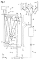
- Fig. 1 shows an adjustment system 10 for adjusting a projection lens 16 of a projection exposure apparatus for microlithography.
- the adjustment system 10 includes a measuring device 12 for determining a state characterization 34 of the projection lens 16 and a control device 14 in shape a so-called travel path determiner for generating a travel command 38 from the state characterization 34th
- the projection objective 16 serves to image mask structures from an object plane 24 into an image plane 28 and may be designed for exposure radiation of different wavelengths, such as e.g. 248 nm or 193 nm. In the present embodiment, the projection objective 16 is tuned to a wavelength in the EUV wavelength range, e.g. 13.5 nm, designed.
- the measuring device 12 is configured to measure wavefront errors of the projection objective 16 and comprises an illumination device 18 and a measurement mask 22 on the input side of the projection objective 16 and a sensor element 26, a detector 30 and an evaluation device 32 on the output side of the projection objective.
- the illumination device 18 is thereto configured to generate a measuring radiation 20 at the operating wavelength of the projection objective 16 to be tested, in the present case in the form of EUV radiation, and to irradiate it onto the measuring mask 22, which is arranged in the object plane 24.
- EUV radiation is to be understood as meaning electromagnetic radiation having a wavelength of less than 100 nm, in particular a wavelength of approximately 13.5 nm or approximately 6.7 nm.
- the measuring mask 22 often also called “coherence mask” has a first periodic structure.
- the sensor element 26 is arranged in the form of an image grid, which has a second periodic structure.
- checkerboard structures in the measurement mask 22 may be combined with checkerboard structures in the sensor element 26.
- Other combinations of periodic structures known to those skilled in the art of shear interferometry or point diffraction interferometry may also be used.
- a two-dimensionally resolving detector 30 is arranged in the form of a camera.
- the sensor element 26 and the Detector 30 together form a sensor module.
- the measuring mask 22 and the sensor module form a shear interferometer or point diffraction interferometer known to the person skilled in the art and serve to measure wavefront errors of the projection objective 16. For this purpose, in particular phase shift methods known to the person skilled in the art are used.
- the evaluation device 32 determines the state characterization 34 of the projection objective 16 from the intensity patterns recorded by the detector 30.
- the state characterization 34 comprises a set of zernike coefficients b j characterizing the wavefront errors of the projection objective 16.
- Z j While the Zernike polynomials are denoted by Z j , ie subscript j, in the context of this application the Zernike coefficients are labeled b j .
- Zj the Zernike coefficients
- b j the Zernike coefficients b j are often also referred to as Zj, ie with a normal index such as Z5 and Z6 for astigmatism.
- the state characterization 34 determined by the evaluation device 32 of the measuring device 12 is transmitted to the control device 14, which generates the travel command 38 therefrom.
- the travel command 38 includes travel paths x i and travel paths x n L , These travel paths x i are used to control manipulators M s of the projection lens 16, while the travel paths x n L serve the control of a post-processing device 36 for mechanical post-processing of optical elements of the projection lens 16.
- both the manipulators M s and also the post-processing device 36 are understood as manipulators of the projection objective 16 in the general sense.
- the projection lens 16 has in the embodiment according to Fig. 1 only four optical elements L1 to L4. All optical elements are movably mounted. For this purpose, each of the optical elements L1 to L4 a respective manipulator M s , in each case one of the manipulators M1 to M4, assigned.
- the manipulators M1, M2 and M3 each allow a shift of the associated optical elements L1, L2 and L3 in the x- and y-direction and thus substantially parallel to the plane in which the respective reflective surface of the optical elements is located.
- the manipulator M4 is configured to tilt the optical element L4 by rotation about a tilting axis 40 arranged parallel to the y-axis. This changes the angle of the reflecting surface of L4 with respect to the incident radiation.
- Other degrees of freedom for the manipulators are conceivable.
- a displacement of a respective optical element transverse to its optical surface or a rotation about a perpendicular to the reflecting surface reference axis may be provided.
- each of the manipulators M1 to M4 shown here is intended to cause a displacement of the associated optical element L1 to L4 while performing a rigid body movement along a predetermined travel.
- a travel for example, combine translations in different directions, tilting and / or rotations in any way.
- manipulators which are configured to perform a different type of change of a state variable of the associated optical element by corresponding actuation of the manipulator.
- an actuation can take place, for example, by acting on the optical element with a specific temperature distribution or a specific distribution of forces.
- the adjustment path may be due to a change in the temperature distribution at the optical element or the application of a local voltage to an optical element designed as a deformable lens or as a deformable mirror.
- the travel ranges x i encompassed by the travel command 38 contain the travel paths x 1 , x 2 , x 3 and x 4 , which predetermine changes to be made by the manipulators M1 to M4 and thus serve to control the manipulators M1 to M4 of the projection objective 16.
- the ascertained travel paths x 1 to x 4 are transmitted to the individual manipulators M1 to M4 via travel signals and indicate these respective correction travel paths to be executed. These define respective displacements of the associated optical elements L1 to L4 occurred for correcting wavefront aberration of the projection lens 16. For the case in which a manipulator having a plurality of degrees of freedom, this can also several adjustment paths are transmitted x i.
- the travels further encompassed by the travel command 38 x n L included in the case shown the travel paths x n 1 . x n 2 . x n 3 and x n 4 . which serve to control the post-processing device 36 for the respective mechanical post-processing of the optical elements L1, L2, L3 or L4 of the projection objective 16.
- the post-processing device 36 is a device for mechanical removal of material on an optical surface of an optical element in the form of a lens or a mirror to understand. This ablation is downstream of the production of the optical element and serves in particular to change a spherical surface into an aspherical surface. A correspondingly reworked optical element is therefore referred to as intrinsically corrected asphere (ICA).
- ICA intrinsically corrected asphere
- As a post-processing device 36 it is possible in particular to use an ablation device which is usually used for the mechanical processing of ICAs. The erosions are therefore also referred to as "ICA erosions" below.
- ICA erosions For mechanical processing, for example, an ion beam can be used. This allows any correction profiles to be incorporated into a reworked optical element.
- control device 14 The operation of the control device 14 will be exemplified below. This is configured to execute a path-generating optimization algorithm.
- the optimization algorithm serves to optimize a quality function H, also called a merit function.
- the positioning paths of the travel command 38 to be generated by the optimization algorithm with a travel variable which comprises a travel vector x and a further travel vector x L , are described below.
- the vector components of the travel vector x are the abovementioned individual travel paths x i of the manipulators provided in the projection objective 16.
- the vector components of Stellwegvektors x L are the control of the ICA post-processing device 36 serving travel as well x n L .
- the travel paths x i and x n L are also referred to as travel variables.
- the state characterization 34 is described with a state vector b, whose vector components are the aforementioned Zernike coefficients b j .
- the Zernike coefficients b j are also referred to as state parameters.
- the sensitivities of the manipulators in the present case of the manipulators M1 to M4, with respect to their degrees of freedom in the event of a state change, are described according to an embodiment variant by means of a sensitivity matrix M.
- the sensitivity matrix M describes the relationship between an adjustment of a degree of freedom i of a manipulator by a standard travel x i 0 and a resulting change in the state vector b of the projection objective 16.
- the path-generating optimization algorithm according to the invention is configured to solve the following optimization problem: min H
- the component H b contains weighted the individual Zernike coefficients b j .
- H f contains specifications regarding so-called fading aberrations.
- a fading aberration is an indication of how an image aberration in the scanning direction of a projection exposure apparatus, ie in the direction of the relative movement between the mask and the wafer, changes during the exposure.
- H ovl contains specifications regarding so-called overlay errors. An overlay error gives a local image position shift of an imaged mask structure over its Target position on the substrate.
- H x describes the boundary conditions of the manipulators M s .
- Hica describes boundary conditions of the ICA removal to be carried out by means of the post-processing device 36.
- H rms contains grouped RMS values of the Zernike coefficients b j .
- an RMS value of coefficients means the root of the sum of the squares of the coefficients.
- H b ⁇ j Mx - b j t j b * S j b 2 n j b
- t j b and n j b user-selectable parameters.
- a so-called "hard” target value is assigned to the respective target value S j b for the corresponding Zernike coefficient.
- the parameter t j b is also used as a weighting factor for the target value S j b designated.
- a "hard target value” means a target value that may only be slightly exceeded or fallen short of.
- H b ⁇ j .DELTA.B j sb j 2 n b
- Hb is thus a linear combination of powers ⁇ b j sb j 2 n b ,
- the base ⁇ b j sb j The powers contain a function of the travel vector x and thus the travel variable x i .
- the aforementioned freely selectable parameters n j b are the associated exponents of the aforementioned powers. Since it is the target value in the present embodiment S j b is a "hard" target value, the respective exponent n j b assigned a value greater than 10, in particular greater than 18. According to one embodiment of the respective exponent is n j b assigned value each in the range of 10 to 30.
- FIG. 3 The diagram shown shows the quality function component H b as a function of the basis ⁇ b j sb j .
- the Function due to the choice of the exponent n j b very steep if ⁇ b j is close in absolute value to the weighted target value sb j .
- Outliers at Zernike coefficients b j ie values of b j above or below the target value, are admittedly permitted but weighted so that they are virtually non-existent.
- the so-called fading aberrations b j f can be calculated from the measured Zernike aberrations b j .
- S j f the target value or specification for the fading aberration b j f .
- the sum m passes over all field points along the scan direction of the projection exposure apparatus.
- the parameter w m designates so-called scan weights, ie weights of the image errors which originate from the scanning movement.
- M f j denotes a sensitivity matrix for the fading aberrations b j f and thus defines the change of the state vector b of the projection lens due to fading aberrations upon adjustment of the manipulators M s by a standard displacement x 0 .
- H f is thus a linear combination of powers ⁇ f j t j f S j f 2 n j f ,
- the base ⁇ f j t j f S j f The powers contain a function of the travel vector x and thus the travel variable x i .
- the aforementioned freely selectable parameters n j f are the associated exponents of the aforementioned powers. Since it is the target value in the present embodiment S j f is a "hard" target value, the respective exponent n j f assigned a value greater than 10, in particular greater than 18. According to one embodiment is the one of the respective exponent n j f assigned value each in the range of 10 to 30.
- Overlay errors are determined for different structure types, such as isolated lines, grid lines, circular structures, and so on.
- the different structure types are designated by the counting variable p.
- An overlay error depending on the structure type p as well as on the field point m is described with the product ( SZ p b ) m .
- SZ p is a matrix which includes field point-dependent weights for the individual Zemike coefficients b j .
- An overlay error (SZ p b) m is thus formed by linear combinations of individual Zernike coefficients b j.
- S p ovl the target value or the specified specification for the overlay error of the structure type p.
- the matrix M is the sensitivity matrix already described above with respect to the goodness function component H b .
- the max function determines the maximum over all field points m.
- H ovl ⁇ m ⁇ p SZ p Mx - SZ p b m t p ovl * S p ovl 2 n p ovl
- H ovl is thus a linear combination of powers SZ p Mx - SZ p b m t p ovl * S p ovl 2 n p ovl ,
- the powers contain a function of the travel vector x and thus the travel variable x i .
- the aforementioned freely selectable parameters n p ovl are the associated exponents of the aforementioned powers. Since it is the target value in the present embodiment S p ovl a "hard" target is acting, the respective exponent n p ovl assigned a value greater than 10, in particular greater than 18. According to one embodiment of the respective exponent is n p ovl assigned value each in the range of 10 to 30.
- the travel paths x i of the manipulators M s have lower limit values x i min and upper limits x i Max on, so that applies: x i min ⁇ x i ⁇ x i Max
- a single x i denotes a degree of freedom of a manipulator M s , wherein the individual manipulators may have one or more degrees of freedom.
- the sum of the count variables i goes over all degrees of freedom of all manipulators M s .
- the user-selectable parameters are t i y and n i y , At the limits x i min and x i Max these are so-called "hard" targets. This is when choosing the appropriate parameter t i y taken into account by the parameter t i y a value in the range of 0.6 to 0.95 is assigned.
- H x is thus a linear combination of powers y i t i y 2 n i y ,
- the powers contain a function of the travel vector x and thus the travel variable x i .
- the aforementioned freely selectable parameters n i y are the associated exponents of the aforementioned powers. Since it is in the present embodiment at the limits x i min and x i Max is "hard" target values, the respective exponent n i y a value greater than 10, in particular greater than 18 assigned. According to one embodiment of the respective exponent n i y assigned value each in the range of 10 to 30.
- the course of the quality function component H x as a function of the base y i t i y is essentially the same as in Fig. 3 illustrated course of the quality function component H b .
- the above with respect to the course of the diagram according to Fig. 3 Explanations made can therefore be transferred to the course of H x .
- H ica describes boundary conditions by means of the post-processing device 36 on individual optical elements, such as the optical elements L1 to L4 of the projection objective 16 according to FIG Fig. 1 , ICA ablation to be performed.
- x K and y K denote the Cartesian x and y coordinates on a respective optical element L.
- the basic functions f O L x K y K are calculated from the measured Zernike coefficients b j of the projection lens 16 using a conversion matrix containing the sensitivities for ICA ablation, according to one embodiment.
- the basic functions contain f O L x K y K a sum of Zernike polynomials.
- the basic functions f O L x K y K also be made up of spline functions, Legendre polynomials, etc.
- PV L Max x K . y K F L x K y K - min x K . y K F L x K y K
- Equation (20) ensures that variations of the profile can not become arbitrarily large.
- S L pv a so-called "soft" target value, which is not as accurate as a "hard” target value.
- Hica ⁇ L ⁇ n 2 f n L x K y K x n L t L pv * S L pv 2 n L pv
- t L pv and n L pv user-selectable parameters.
- the parameter becomes t L p ⁇ a value in the range assigned from 0.5 to 2.0.
- the parameter t L p ⁇ is also used as a weighting factor for the target value S L pv designated.
- H ica is thus a linear combination of powers 2 f n L x K y K x n L t L pv * S L pv 2 n L pv
- the base 2 f n L x K y K x n L t L pv * S L pv of the powers contains a function of the travel path vector x L described above and thus the travel variables x n L
- the aforementioned freely selectable parameters n L p ⁇ are the associated exponents of the aforementioned powers. Since it is the target value in the present embodiment S L pv becomes an "what" target, becomes the exponent n L p ⁇ assigned a value of 3 to 10.
- the course of the quality function component H ica as a function of the basis 2 f n L x K y K x n L t L pv * S L pv is different from the one in Fig. 3 shown course of the quality function component H b essentially in that the approach to the arranged at -1 and +1 vertical lines is less steep and the lines are exceeded more.
- RMS r Max m ⁇ j ⁇ j r Mx - b j . m 2
- r is a count variable of the grouped RMS value RMS r .
- the grouping is done, for example, by classifying the corresponding Zernike coefficients b j into the categories "spherical aberrations", "coma”, "astigmatism", etc.
- the sum over j is a sum over the Zernike orders, ⁇ j r the weights of the individual Zernike contributions b j to the RMS value with the index r and the maximum is determined over all field points m of the image field of the projection lens 16.
- the grouped RMS values RMS r comprise, according to different embodiments, all Zernike coefficients Z j with j ⁇ 10, with j ⁇ 25, with j ⁇ 49, with j ⁇ 64 or with j ⁇ 100.
- H rms the target value or specification for the RMS value with the index r.
- this t r rms and n r rms user-selectable parameters.
- S r rms for the corresponding RMS value is according to one embodiment, a so-called "hard" target value. This becomes possible when choosing the respective parameter t r rms taken into account by the parameter t r rms a value in the range of 0.6 to 0.95 is assigned. Of the parameter t r rms is also used as a weighting factor for the target value S r rms designated.
- H rms is thus a linear combination of powers ⁇ j ⁇ r j Mx - b j . m 2 t r rms S r rms 2 n r rms
- the powers contain a function of the travel vector x and thus the travel variable x i .
- the aforementioned freely selectable parameters n r rms are the associated exponents of the aforementioned powers.
- S r rms is a "hard" target value
- the exponent is located n r rms assigned value in the range of 20 to 60.
- the course of the quality function component H rms as a function of the basis ⁇ j ⁇ r j Mx - b j . m 2 t r rms S r rms 2 is essentially the same as in Fig. 3 illustrated course of the quality function component H b .
- the above with respect to the course of the diagram according to Fig. 3 Explanations given can therefore be transferred to the course of H rms .
- n j b . n j f . n p ovl . n i y . n L pv and n r rms are chosen so that the resulting in the individual quality function components exponent 2 n j b . 2 n j f . 2 n p ovl . 2 n i y . 2 n L pv and n r rms have at least two different values. In other words, there is at least one exponent, whose value deviates from those of the other exponents. According to further embodiments, the aforementioned exponents have a multiplicity of different values, in particular each of the exponents has a different value. In this way, the weightings of the different optimization variables can be set individually in the optimization, and thus the optimization result can be optimally adapted to the existing boundary conditions.
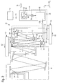
- Fig. 2 shows an embodiment according to the invention of a projection exposure apparatus 50 for microlithography.
- the present embodiment is designed for operation in the EUV wavelength range. Due to this operating wavelength, all optical elements are designed as mirrors.
- the invention is not limited to projection exposure systems in the EUV wavelength range. Further embodiments according to the invention are designed, for example, at operating wavelengths in the UV range, such as, for example, 365 nm, 248 nm or 193 nm. In this case, at least some of the optical elements are configured as conventional transmission lenses.
- the projection exposure apparatus 10 includes an exposure radiation source 52 for generating exposure radiation 54.
- the exposure radiation source 52 is implemented as an EUV source and may comprise, for example, a plasma radiation source.
- the exposure radiation 54 first passes through an illumination optical system 56 and is directed by the latter onto a mask 58.
- the illumination optics 56 are configured to produce different angular distributions of the exposure radiation 54 incident on the mask 58.
- the illumination optics 56 configure the angular distribution of exposure radiation 54 incident on the mask 58. Examples of selectable illumination settings include so-called dipole illumination, annul illumination, and quadrupole illumination.
- the mask 58 has mask structures for imaging on a substrate 64 in the form of a wafer and is mounted displaceably on a mask shift stage 60.
- the mask 58 may, as in Fig. 2 shown, be designed as a reflection mask or alternatively, in particular for UV lithography, also be configured as a transmission mask.
- the exposure radiation 54 is used in the embodiment according to FIG Fig. 2 then reflected on the mask 58 and then passes through the already with reference to the alignment system 10 according to Fig. 1
- the projection objective is used to image the mask structures of the mask 58 onto the substrate 64.
- the exposure radiation 54 is guided within the projection objective 16 by means of a multiplicity of optical elements, here in the form of mirrors.
- the substrate 64 is displaceably mounted on a substrate shifting platform 66.
- the projection exposure apparatus 50 can be embodied as a so-called scanner or as a so-called stepper.
- the fading aberrations described above in connection with the description of the goodness function component H f are based on the scan movements during the field exposure of a attributed to such a scanner.
- the projection exposure apparatus 50 further comprises a central control device 72 for controlling the exposure process, including the mask transfer stage 60 and the substrate transfer stage 66.
- the projection exposure apparatus 10 further comprises a control device 114 for controlling the manipulators M1 to M4.
- the control device 114 in turn comprises a state transmitter 80 and a travel path determiner 86.
- the state generator 80 transfers current state characterizations 34a of the projection lens 16 to the travel path determiner 86, which generates a travel command 138 therefrom.
- the Stellwegbetation 138 includes adjustment paths x i, in the case shown, the adjustment paths x 1, x 2, x 3 and x 4mm. These adjustment paths are used to control the manipulators M1 to M4, as described above in relation to the adjustment system 10 according to FIG Fig. 1 described in more detail.
- the Stellwegbelist generated by the actuator travel investigators 86,138 encompassed by the manipulators M1 to M4 to be executed changes in the form of adjustment paths x i corresponding state variables of the optical elements L1 to L4.
- the determined adjustment paths x i are transmitted to the individual manipulators M1 to M4 on Stellwegsignale and specify these respective correction adjustment paths to be executed. These define respective displacements of the associated optical elements L1 to L4 for the correction of occurred wavefront aberration of the projection lens 16.
- each updated state characterizations 34a in the shape of the wavefront characterizing Zernike coefficients b j are updated.
- the travel determiner 86 generates multiple updated travel paths x i during the exposure of a substrate 64.
- the state generator 80 has a memory 82 and a simulation device 84.
- state characterizations 34 are stored in the form of aberration parameters, which have been determined by means of a wavefront measurement on the projection lens 16. These measurement results can be obtained by means of an external wavefront measuring device such as that described in US Pat Fig. 1 described measuring device 12, are collected.
- the state characterizations 34 can also be measured by a wavefront measuring device 70 integrated in the substrate shifting platform 66. Such a measurement can take place regularly, for example, after every exposure of a wafer or after exposure of a complete wafer set.
- a simulation or a combination of simulation and reduced measurement can be made.
- the measured values of the state characterization 34 in the form of aberration parameters in the form of Zernike coefficients stored in the memory 82 are optionally adapted by the simulation device 84 to respective updated conditions during the exposure process.
- the simulation device 84 is regularly supplied by the central control device 72 with the current irradiation intensity 74. Based on the respective illumination setting on the basis of lens heating, the simulation device 84 calculates changes in the aberration parameters caused thereby. Furthermore, the simulation device continuously receives measured values of a pressure sensor 76 monitoring the ambient pressure of the projection exposure apparatus 10. Effects of changes in the ambient pressure on the aberration parameters are taken into account by the simulation device 84.
- the control device 114 of the projection exposure apparatus 50 according to FIG Fig. 2 differs from the control device 14 of the adjustment system 10 according to Fig. 1 in that the control device 114 uses the state generator 80 to convert the state characterization 34 measured by a wavefront measuring device into a current state characterization 34a using the current illumination intensity 74.
- the function of the adjustment path determiner 86 of the control device 114 corresponds to the function of the controller 14, but with the restriction that the actuating travel command generated by the control device 114,138, only the Stellwegvektor x of the adjustment paths x i of the manipulators, but not the Stellwegvektor x L for controlling ICA post-processing device 36 includes.
Landscapes
- Physics & Mathematics (AREA)
- General Physics & Mathematics (AREA)
- Optics & Photonics (AREA)
- Exposure And Positioning Against Photoresist Photosensitive Materials (AREA)
- Mounting And Adjusting Of Optical Elements (AREA)
- Lens Barrels (AREA)
- Exposure Of Semiconductors, Excluding Electron Or Ion Beam Exposure (AREA)
Abstract
Description
- Die vorliegende Anmeldung beansprucht die Priorität der
deutschen Patentanmeldung 10 2015 206 448.4 vom 10. April 2015 . Die gesamte Offenbarung dieser Patentanmeldung wird durch Bezugnahme in die vorliegende Anmeldung aufgenommen. - Die Erfindung betrifft eine Steuerungsvorrichtung sowie ein Verfahren zur Steuerung mindestens eines Manipulators eines Projektionsobjektivs für die Mikrolithographie. Weiterhin betrifft die Erfindung eine Justieranlage zur Justierung eines Projektionsobjektivs für die Mikrolithographie sowie eine Projektionsbelichtungsanlage für die Mikrolithographie, jeweils mit einer derartigen Steuerungsvorrichtung.
- Eine Projektionsbelichtungsanlage für die Mikrolithographie dient bei der Herstellung von Halbleiter-Bauelementen der Erzeugung von Strukturen auf einem Substrat in Gestalt eines Halbleiterwafers. Dazu umfasst die Projektionsbelichtungsanlage ein mehrere optische Elemente aufweisendes Projektionsobjektiv zum Abbilden von Maskenstrukturen auf den Wafer während eines Belichtungsvorganges.
- Zur Gewährleistung einer möglichst präzisen Abbildung der Maskenstrukturen auf den Wafer wird ein Projektionsobjektiv mit möglichst geringen Wellenfrontaberrationen benötigt. Projektionsobjektive werden daher mit Manipulatoren ausgestattet, die es ermöglichen Wellenfrontfehler durch Zustandsveränderung einzelner optischer Elemente des Projektionsobjektivs zu korrigieren. Beispiele für eine derartige Zustandsveränderung umfassen: eine Lageänderung in einem oder mehreren der sechs Starrkörperfreiheitsgrade des betreffenden optischen Elements, eine Beaufschlagung des optischen Elements mit Wärme und/oder Kälte, eine Deformation des optischen Elements oder eine Materialabtragung an einem optischen Element mittels einer Nachbearbeitungseinrichtung. Im Rahmen dieser Anmeldung wird auch eine derartige Nachbearbeitungseinrichtung als Manipulator des Projektionsobjektivs im allgemeinen Sinn verstanden.
- Die Berechnung von zur Korrektur einer Aberrationscharakteristik eines Projektionsobjektiv auszuführenden Manipulatorveränderungen erfolgt mittels eines stellwegsgenerierenden Optimierungsalgorithmus, welcher auch "Manipulatorveränderungsmodell" bezeichnet wird. Derartige Optimierungsalgorithmen sind beispielsweise in
WO 2010/034674 A1 beschrieben. - So können aus dem Stand der Technik bekannte Optimierungsalgorithmen zur Lösung des folgenden Optimierungsproblems konfiguriert sein:

- Ein derartiges Optimierungsproblem ist dazu konfiguriert, die durch


- Unter "Stellweg" wird eine mittels Manipulator-Aktuierung erfolgende Veränderung einer Zustandsgröße eines optischen Elements entlang des Stellwegs zum Zweck der Veränderung seiner optischen Wirkung verstanden. Ein derartiger, durch Veränderung einer Zustandsgröße des optischen Elements definierter Stellweg wird über Solländerungsgrößen des zugehörigen Manipulators spezifiziert. Die Manipulation kann beispielsweise in einer Verlagerung des optischen Elements in eine spezielle Richtung, aber auch beispielsweise in einer, insbesondere lokalen oder flächigen, Beaufschlagung des optischen Elements mit Wärme, Kälte, Kräften, Licht einer bestimmten Wellenlänge oder Strömen bestehen. Weiterhin kann die Manipulation eine mittels einer Nachbearbeitungseinrichtung vorzunehmende Materialabtragung an einem optischen Element definieren. Die Solländerungsgröße kann beispielsweise im Falle einer Verlagerung eine zurückzulegende Weglänge oder einen zurückzulegenden Winkelbereich definieren.
- Die durch

- Es ist eine Aufgabe der Erfindung, eine Steuerungsvorrichtung sowie ein Verfahren der eingangs genannten Art bereitzustellen, womit die vorgenannten Probleme gelöst werden, und insbesondere die Qualität eines damit generierten Stellwegbefehls verbessert werden kann.
- Die vorgenannte Aufgabe kann erfindungsgemäß beispielsweise gelöst werden mit einer Steuerungsvorrichtung zur Steuerung mindestens eines Manipulators eines Projektionsobjektivs für die Mikrolithographie. Die Steuerung des mindestens einen Manipulators erfolgt durch Generierung eines Stellwegbefehls, welcher eine vorzunehmende Veränderung einer optischen Wirkung mindestens eines optischen Elements des Projektionsobjektivs durch Manipulation einer Eigenschaft des optischen Elements mittels des mindestens einen Manipulators entlang eines Stellweges definiert. Die Steuerungsvorrichtung ist dazu konfiguriert, aus einer Zustandscharakterisierung des Projektionsobjektivs den Stellwegbefehl für den mindestens einen Manipulator durch Optimierung einer Gütefunktion zu generieren. Die Gütefunktion umfasst dabei eine Linearkombination mindestens zweier Potenzen. Eine die Manipulation der Eigenschaft des optischen Elements definierende Einstellung des mindestens einen Manipulators wird mittels einer Stellwegvariablen dargestellt und die jeweilige Basis der mindestens zwei Potenzen enthält eine Funktion der Stellwegvariablen. Weiterhin weisen die Exponenten der mindestens zwei Potenzen unterschiedliche Werte auf.
- Das genannte Projektionsobjektiv umfasst mehrere optische Elemente und dient im Betrieb einer das Projektionsobjektiv umfassenden Projektionsbelichtungsanlage zur Abbildung von Maskenstrukturen aus einer Maskenebene auf einen in einer Waferebene der Projektionsbelichtungsanlage angeordneten Wafer. Die Steuerungsvorrichtung kann auch als Stellwegsermittler bezeichnet werden.
- Die Stellwegvariable kann als skalare Variable zur Darstellung lediglich einer Manipulatoreinstellung oder als vektorielle Variable zur Darstellung der Einstellungen mehrerer Manipulatoren vorliegen. Der Stellwegbefehl umfasst mindestens einen von dem mindestens einen Manipulator auszuführenden Stellweg. Dabei erfolgt die Ausführung des Stellwegs durch Manipulation einer Eigenschaft des optischen Elements entlang des Stellwegs. Die Gütefunktion, welche auch als "Meritfunktion" bezeichnet werden kann, umfasst eine Linearkombination, insbesondere eine Summe mindestens zweier Potenzen. Mit anderen Worten umfasst die Gütefunktion mindestens zwei Summanden, die ggf. bei der Summierung gewichtet werden können, und die jeweils durch eine Potenz gebildet sind. Gemäß der allgemein in der Mathematik gültigen Definition weist jede der Potenzen eine Basis und einen Exponenten auf.
- Die jeweilige Basis der beiden Summanden enthält eine Funktion der Stellwegvariablen. Die Werte der Exponenten der mindestens zwei Potenzen unterscheiden sich voneinander. Durch die Zuweisung unterschiedlicher Werte an die Exponenten kann die Gütefunktion derart gestaltet werden, dass Zielwerte für mindestens zwei unterschiedliche, bei der Optimierung relevante, Größen mit unterschiedlichen, gezielt ausgewählten, Widerstandseigenschaften versehen werden. Derartige Größen können z.B. Verfahrwegsgrenzen von Manipulatoren, mittels mechanischer Nachbearbeitung erfolgende Materialabtragung an optischen Elementen des Projektionsobjektivs, Bildfehler des Projektionsobjektivs, Fading-Aberrationen des Projektionsobjektivs oder Overlay-Fehler des Projektionsobjektivs umfassen. Unter einer Widerstandseigenschaft eines Zielwerts wird verstanden, wie genau der Zielwert bei der Optimierung einzuhalten ist.
- Ein Zielwert, der eine unbedingt einzuhaltende Grenze oder eine Grenze darstellt, von der nur minimal abgewichen werden darf, weist in diesem Fall eine maximale Widerstandseigenschaft auf und wird in diesem Zusammenhang als "harter" Zielwert bezeichnet. Ein Zielwert, der zwar idealerweise eingehalten werden soll, von dem jedoch auch Abweichungen toleriert werden können, wenn dafür andere Eigenschaften der Optimierung, insbesondere andere Zielwerte, besser erfüllt werden, wird in diesem Zusammenhang als "weicher" Zielwert bezeichnet.
- Die unterschiedlichen Potenzen der Gütefunktion können Gütefunktionskomponenten bzw. Teilgütefunktionen definieren, die jeweils eine andere der vorstehend genannten, unterschiedlichen, bei der Optimierung relevanten Größen mit zugeordneten Zielwerten in Bezug setzen. Durch das erfindungsgemäße Vorsehen unterschiedlicher Werte für die Exponenten der mindestens zwei Potenzen der Gütefunktion ist es möglich, die Zielwerte der unterschiedlichen Größen mit unterschiedlichen Widerstandseigenschaften zu versehen und damit die Signifikanz der Größen in der Optimierung gezielt zu steuern. Insbesondere können die verschiedenen Größen unterschiedlich gewichtet werden. Mit anderen Worten kann gezielt zwischen wichtigeren und unwichtigeren Größen in der Optimierung unterschieden werden. Damit wird die Qualität der Optimierungsergebnisse und damit die Brauchbarkeit des generierten Stellwegbefehls verbessert.
- Gemäß einer Ausführungsform ist die Steuerungsvorrichtung zur Steuerung des mindestens einen Manipulators eines zum Betrieb im EUV-Wellenlängenbereich konfigurierten Projektionsobjektivs ausgebildet.
- Gemäß einer weiteren Ausführungsform nach der Erfindung weisen die mindestens zwei Potenzen unterschiedliche Basen auf. Damit können durch gezielte Anpassung der Basen Widerstandseigenschaften der bei der Optimierung relevanten Größen noch feiner und gezielter eingestellt werden. Die gezielte Anpassung der Basen kann beispielsweise durch geeignete Wahl von Gewichtungsparametern der den Größen zugeordneten Zielwerten erfolgen. Gemäß einer alternativen Ausführungsform weisen die mindestens zwei Potenzen mit unterschiedlichen Exponenten die gleiche Basis auf. Dies kann z.B. im Rahmen der Konfiguration der Gütefunktion als Taylorreihenentwicklung erfolgen.
- Gemäß einer weiteren Ausführungsform weisen die Exponenten der mindestens zwei Potenzen Werte von jeweils größer oder gleich zwei auf. Damit weisen die Exponenten der mindestens zwei Potenzen unterschiedliche Werte von jeweils größer oder gleich zwei auf. Gemäß einer Ausführungsvariante weisen die Exponenten der mindestens zwei Potenzen Werte von jeweils größer oder gleich drei, insbesondere von größer oder gleich vier bzw. von größer oder gleich fünf auf. Durch die entsprechende Wahl der Werte der Potenzen ergibt sich ein gewisses Mindestmaß für die Steilheit der auf die jeweilige Potenz zurückgehenden Komponente der Gütefunktion und damit eine verbesserte Einhaltung von Zielwerten, die den bei der Optimierung relevanten Größen zugeordnet sind.
- Gemäß einer weiteren Ausführungsform enthält die jeweilige Basis der mindestens zwei Potenzen jeweils einen Quotienten, dessen Zähler einen die Funktion der Stellwegvariablen enthaltenden Term umfasst und dessen Nenner einen Zielwert für den Term des Zählers sowie einen Gewichtungsfaktor für den Zielwert aufweist. Gemäß einer Ausführungsvariante weist der Gewichtungsfaktor einen Wert von mindestens 0,5 auf, insbesondere liegt der Wert zwischen 0,5 und 2,0. Gemäß einer Ausführungsform liegt der Gewichtungsfaktor der Basis der ersten Potenz im Bereich von 0,5 bis 2,0 und der Gewichtungsfaktor der Basis der zweiten Potenz liegt im Bereich von 0,6 und 0,95. Die erste Potenz bildet damit zumindest eine Komponente einer Teilgütefunktion mit einem "harten" Zielwert, während die zweite Potenz zumindest eine Komponente einer Teilgütefunktion mit einem "weichen" Zielwert bildet. Die gesamte Gütefunktion gewichtet damit zumindest zwei Zielwerte entsprechend unterschiedlich.
- Gemäß einer weiteren Ausführungsform weist die Gütefunktion zumindest eine Komponente auf, die eine konvexe oder eine konkave Funktion der Stellwegsvariablen ist. Insbesondere ist die gesamte Gütefunktion eine konvexe oder eine konkave Funktion der Stellwegsvariablen.
- Gemäß einer weiteren Ausführungsform beträgt eine Differenz der Werte der beiden Exponenten mindestens 5, insbesondere mindestens 10. Gemäß einer Ausführungsvariante weist der Exponent der ersten Potenz einen Wert von mindestens 20, insbesondere einen Wert von größer als 36 auf. Gemäß einem Ausführungsbeispiel weist der Exponent der ersten Potenz einen Wert im Bereich von 20 bis 60, und der Exponent der zweiten Potenz einen Wert im Bereich von 6 bis 10 auf. Die erste Potenz bildet damit zumindest eine Komponente einer Teilgütefunktion mit einem "harten" Zielwert, während die zweite Potenz zumindest eine Komponente einer Teilgütefunktion mit einem "weichen" Zielwert bildet. Die gesamte Gütefunktion gewichtet damit zumindest zwei Zielwerte entsprechend unterschiedlich.
- Gemäß einer weiteren Ausführungsform ist die Steuerungsvorrichtung zur Steuerung mehrerer Manipulatoren konfiguriert, die Zustandscharakterisierung umfasst mehrere durch einen Zustandsvektor charakterisierte Zustandsparameter, und jeder der Potenzen umfasst eine Sensitivitätsmatrix, welche einen Zusammenhang zwischen den Stellwegen der Manipulatoren und dem Zustandsvektor definiert. Mit anderen Worten bezeichnet die Sensititivätsmatrix die Sensitivität der Manipulatoren in Bezug auf deren Bewegungsfreiheitsgrade. Bezogen auf einen Manipulator Ms definiert die Sensitivitätsmatrix, wie sich der Zustandsvektor des Projektionsobjektivs verändert, wenn der Manipulator Ms um einen Standard-Stellweg verstellt wird.
- Gemäß einer weiteren Ausführungsform umfasst eine der Potenzen einen Term, welcher einen Bildfehler des Projektionsobjektivs beschreibt. Insbesondere wird dabei der Bildfehler mittels Zernike-Koeffizienten beschrieben.
- Gemäß einer weiteren Ausführungsform umfasst eine der Potenzen einen Term, welcher eine Fading-Aberration einer Step- und Scan Projektionsbelichtungsanlage für die Mikrolithographie beschreibt. Bei einer Step-und-Scan-Projektionsbelichtungsanlage bewegen sich während der Abbildung einer Maske auf einen Wafer die Maske und der Wafer relativ zueinander. Unter einer Fading-Aberration ist eine Angabe zu verstehen, wie sich ein Bildfehler in Scanrichtung, d.h. in Richtung der Relativbewegung zwischen Maske und Wafer bei der Belichtung, verändert.
- Gemäß einer weiteren Ausführungsform umfasst eine der Potenzen einen Term, welcher einen quadratischen Mittelwert einer Auswahl von Bildfehlern des Projektionsobjektivs beschreibt. Der quadratische Mittelwert wird auch als "RMS-Wert" bezeichnet. Der Exponent der den quadratischen Mittelwert einer Auswahl von Bildfehlern beschreibenden Potenz hat gemäß einer Ausführungsform einen Wert von mindestens 10, insbesondere fällt der Wert in den Bereich von 10 bis 30. Damit bildet diese Potenz zumindest eine Komponente einer Teilgütefunktion mit einem "harten" Zielwert. Die Auswahl an Bildfehlern für den quadratischen Mittelwert umfasst beispielsweise alle Zernike-Koeffizienten Zj mit j ≤ 100, insbesondere mit j ≤ 64, j ≤ 49, j ≤ 25 oder j ≤ 10. Die Definition der ZernikeKoeffizienten Zj wird nachstehend erläutert.
- Gemäß einer weiteren Ausführungsform umfasst eine der Potenzen einen Term, welcher einen reinen Overlay-Fehler beschreibt. Ein Overlay-Fehler gibt eine lokale Bildlageverschiebung einer abgebildeten Maskenstruktur gegenüber deren Solllage auf dem Substrat an.
- Gemäß einer weiteren Ausführungsform umfasst eine der Potenzen einen Term, welcher einen mittels mechanischer Nachbearbeitung eines optischen Elements des Projektionsobjektivs korrigierbaren Fehler beschreibt. Derartige Fehler sind beispielsweise bei sogenannten intrinsisch korrigierten Asphären (ICA's) korrigiert. Diese Fehler werden durch nachgelagerte mechanische Bearbeitung einer als optisches Element dienenden Asphäre reduziert bzw. eliminiert.
- Gemäß einer weiteren Ausführungsform enthält die Gütefunktion mindestens eine implizite Nebenbedingung für den Stellweg. Eine derartige implizite Nebenbedingung wird im Rahmen der Gütefunktion beschrieben, wie dies beispielsweise bei der auf Seite 45 von
WO2010/034674A1 unter (av) beschriebenen Gütefunktion einer Tikhonov-Regularisierung der Fall ist. Im Gegensatz dazu werden explizite Nebenbedingugen außerhalb der Gütefunktion beschrieben. - Weiterhin wird erfindungsgemäß eine Justieranlage zur Justierung eines Projektionsobjektivs für die Mikrolithographie bereitgestellt. Die Justieranlage umfasst eine Messvorrichtung zur Ermittlung der Zustandscharakterisierung des Projektionsobjektivs, sowie eine Steuerungsvorrichtung in einer der vorstehend beschriebenen Ausführungsformen zur Generierung des Stellwegbefehls aus der Zustandscharakterisierung.
- Gemäß einer Ausführungsform der Justieranlage ist die Messvorrichtung als Wellenfrontmesseinrichtung konfiguriert. Eine Wellenfrontmesseinrichtung kann insbesondere als Interferometer, wie etwa als Fizeau-Interferometer, oder als Shack-Hartmann-Sensor konfiguriert sein.
- Weiterhin wird erfindungsgemäß eine Projektionsbelichtungsanlage für die Mikrolithographie bereitgestellt. Die Projektionsbelichtungsanlage umfasst ein Projektionsobjektiv zum Abbilden von Maskenstrukturen, mindestens einen Manipulator, welcher dazu konfiguriert ist, eine optische Wirkung mindestens eines optischen Elements des Projektionsobjektivs durch Manipulation einer Eigenschaft des optischen Elements entlang eines Stellweges zu verändern, sowie eine Steuerungsvorrichtung in einer der vorstehend beschriebenen Ausführungformen zur Steuerung des mindestens einen Manipulators.
- Die von der Projektionsbelichtungsanlage umfasste Steuerungsvorrichtung kann gemäß einer Ausführungsform eine Simulationseinrichtung umfassen, welche dazu konfiguriert ist, Veränderungen in den optischen Eigenschaften des mindestens einen optischen Elements, die durch Erwärmung des optischen Elements erfolgen, zu simulieren und die Zustandscharakterisierung auf Grundlage des Simulationsergebnisses zu bestimmen. Gemäß einer weiteren Ausführungsform ist die Projektionsbelichtungsanlage zum Betrieb im EUV-Wellenlängenbereich konfiguriert.
- Weiterhin wird erfindungsgemäß ein Verfahren zum Steuern mindestens eines Manipulators eines Projektionsobjektivs für die Mikrolithographie bereitgestellt. Das Verfahren umfasst ein Generieren eines Stellwegbefehls für den mindestens einen Manipulator durch Ausführen einer Optimierung einer Gütefunktion. Dabei umfasst die Gütefunktion eine Linearkombination mindestens zweier Potenzen. Eine die Manipulation der Eigenschaft des optischen Elements definierende Einstellung des mindestens einen Manipulators wird mittels einer Stellwegvariablen dargestellt und die jeweilige Basis der mindestens zwei Potenzen enthält eine Funktion der Stellwegvariablen. Weiterhin weisen die Exponenten der mindestens zwei Potenzen unterschiedliche Werte auf. Weiterhin umfasst das Verfahren ein Verändern einer optischen Wirkung mindestens eines optischen Elements des Projektionsobjektivs durch Manipulation einer Eigenschaft des optischen Elements mittels des mindestens einen Manipulators entlang eines durch den generierten Stellwegbefehl definierten Stellweges.
- Gemäß einer Ausführungsform erfolgt das Generieren des Stellwegbefehls mittels der Steuerungsvorrichtung in einer der vorstehenden beschriebenen Ausführungsformen.
- Die bezüglich der vorstehend aufgeführten Ausführungsformen, Ausführungsbeispiele bzw. Ausführungsvarianten, etc. der erfindungsgemäßen Steuerungsvorrichtung angegebenen Merkmale können entsprechend auf das erfindungsgemäße Verfahren übertragen werden. Umgekehrt können die bezüglich der vorstehend ausgeführten Ausführungsformen, Ausführungsbeispiele bzw. Ausführungsvarianten des erfindungsgemäßen Verfahrens angegebenen Merkmale entsprechend auf die erfindungsgemäße Steuerungsvorrichtung übertragen werden. Diese und andere Merkmale der erfindungsgemäßen Ausführungsformen werden in der Figurenbeschreibung und den Ansprüchen erläutert. Die einzelnen Merkmale können entweder separat oder in Kombination als Ausführungsformen der Erfindung verwirklicht werden. Weiterhin können sie vorteilhafte Ausführungsformen beschreiben, die selbstständig schutzfähig sind und deren Schutz ggf. erst während oder nach Anhängigkeit der Anmeldung beansprucht wird.
- Die vorstehenden, sowie weitere vorteilhafte Merkmale der Erfindung werden in der nachfolgenden detaillierten Beschreibung beispielhafter erfindungsgemäßer Ausführungsformen unter Bezugnahme auf die beigefügten schematischen Zeichnungen veranschaulicht. Es zeigt:
-
Fig. 1 eine Veranschaulichung einer erfindungsgemäßen Ausführungsform einer Steuerungsvorrichtung zur Steuerung von Manipulatoren eines Projektionsobjektivs für die Mikrolithographie sowie einer Nachbearbeitungseinrichtung, -
Fig. 2 eine Veranschaulichung einer erfindungsgemäßen Ausführungsform einer Projektionsbelichtungsanlage für die Mikrolithographie mit einem Projektionsobjektiv sowie einer Steuerungsvorrichtung zur Steuerung von Manipulatoren des Projektionsobjektivs, sowie -
Fig. 3 ein den Verlauf einer Gütefunktionskomponente veranschaulichendes Diagramm, welche Teil einer Gütefunktion eines in der Steuerungsvorrichtung ablaufenden Optimierungsalgoritmusses ist. - In den nachstehend beschriebenen Ausführungsbeispielen bzw. Ausführungsformen oder Ausführungsvarianten sind funktionell oder strukturell einander ähnliche Elemente soweit wie möglich mit den gleichen oder ähnlichen Bezugszeichen versehen. Daher sollte zum Verständnis der Merkmale der einzelnen Elemente eines bestimmten Ausführungsbeispiels auf die Beschreibung anderer Ausführungsbeispiele oder die allgemeine Beschreibung der Erfindung Bezug genommen werden.
- Zur Erleichterung der Beschreibung ist in der Zeichnung ein kartesisches xyz-Koordinatensystem angegeben, aus dem sich die jeweilige Lagebeziehung der in den Figuren dargestellten Komponenten ergibt. In
Fig. 1 verläuft die y-Richtung senkrecht zur Zeichenebene in diese hinein, die x-Richtung nach rechts und die z-Richtung nach oben. -
Fig. 1 zeigt eine Justieranlage 10 zur Justierung eines Projektionsobjektivs 16 einer Projektionsbelichtungsanlage für die Mikrolithographie. Die Justieranlage 10 umfasst eine Messvorrichtung 12 zur Ermittlung einer Zustandscharakterisierung 34 des Projektionsobjektivs 16 sowie eine Steuerungsvorrichtung 14 in Gestalt eines sogenannten Stellwegsermittlers zur Generierung eines Stellwegbefehls 38 aus der Zustandscharakterisierung 34. - Das Projektionsobjektiv 16 dient zum Abbilden von Maskenstrukturen aus einer Objektebene 24 in eine Bildebene 28 und kann auf Belichtungsstrahlung unterschiedlicher Wellenlängen ausgelegt sein, wie z.B. 248 nm oder 193 nm. In der vorliegenden Ausführungsform ist das Projektionsobjektiv 16 auf eine Wellenlänge im EUV-Wellenlängenbereich, z.B. 13,5 nm, ausgelegt.
- Die Messvorrichtung 12 ist zum Vermessen von Wellenfrontfehlern des Projektionsobjektivs 16 konfiguriert und umfasst auf der Eingangsseite des Projektionsobjektivs 16 eine Beleuchtungseinrichtung 18 und eine Messmaske 22 sowie auf der Ausgangsseite des Projektionsobjektivs ein Sensorelement 26, einen Detektor 30 sowie eine Auswerteeinrichtung 32. Die Beleuchtungseinrichtung 18 ist dazu konfiguriert eine Messstrahlung 20 mit der Betriebswellenlänge des zu testenden Projektionsobjektivs 16, im vorliegenden Fall in Gestalt von EUV-Strahlung, zu erzeugen und diese auf die Messmaske 22, welche in der Objektebene 24 angeordnet ist, einzustrahlen. Unter EUV-Strahlung ist im Rahmen dieser Anmeldung elektromagnetische Strahlung einer Wellenlänge kleiner als 100 nm, insbesondere einer Wellenlänge von etwa 13,5 nm oder etwa 6,7 nm zu verstehen. Die Messmaske 22, oft auch "Kohärenzmaske" bezeichnet, weist eine erste periodische Struktur auf. In der Bildebene 28 ist das Sensorelement 26 in Gestalt eines Bildgitters angeordnet, welches eine zweite periodische Struktur aufweist. Auch können Schachbrettstrukturen in der Messmaske 22 mit Schachbrettstrukturen im Sensorelement 26 kombiniert werden. Auch andere dem Fachmann aus dem Gebiet der Scherinterferometrie oder der Punktbeugungsinterferometrie bekannte, Kombinationen von periodischen Strukturen können Verwendung finden.
- Unterhalb des Sensorelements 26, und zwar in einer zur Pupillenebene des Projektionsobjektivs 16 konjugierten Ebene, ist ein zweidimensional-auflösender Detektor 30 in Gestalt einer Kamera angeordnet. Das Sensorelement 26 und der Detektor 30 bilden zusammen ein Sensormodul. Die Messmaske 22, und das Sensormodul bilden ein dem Fachmann bekanntes Scherinterferometer oder Punktbeugungsinterferometer und dienen dazu, Wellenfrontfehler des Projektionsobjektivs 16 zu vermessen. Dazu werden insbesondere dem Fachmann bekannte Phasenschiebeverfahren angewendet.
- Die Auswerteeinrichtung 32 ermittelt aus den vom Detektor 30 aufgezeichneten Intensitätsmustern die Zustandscharakterisierung 34 des Projektionsobjektivs 16. Gemäß der vorliegenden Ausführungsform umfasst die Zustandscharakterisierung 34 einen die Wellenfrontfehler des Projektionsobjektivs 16 charakterisierenden Satz an Zernikekoeffizienten bj.
- In der vorliegenden Anmeldung werden, wie beispielsweise in den Abschnitten [0125] bis [0129] von
US 2013/0188246A1 beschrieben, die aus z.B. Kapitel 13.2.3 des Lehrbuchs "Optical Shop Testing", 2nd Edition (1992) von Daniel Malacara, Hrsg. John Wiley & Sons, Inc. bekannten Zernikefunktionen

- Während die Zernike-Polynome mit Zj, d.h. mit tiefergestelltem Index j, bezeichnet werden, werden im Rahmen dieser Anmeldung die Zernike-Koeffizienten mit bj bezeichnet. An dieser Stelle sei angemerkt, dass in der Fachwelt die ZernikeKoeffizienten bj oft auch mit Zj, d.h. mit normal gestelltem Index, wie beispielsweise Z5 und Z6 für Astigmatismus, bezeichnet werden.
- Die von der Auswerteeinrichtung 32 der Messvorrichtung 12 ermittelte Zustandscharakterisierung 34 wird an die Steuerungsvorrichtung 14 übergeben, welche daraus den Stellwegbefehl 38 erzeugt. Der Stellwegbefehl 38 umfasst Stellwege xi sowie Stellwege


- Das Projektionsobjektiv 16 weist in der Ausführungsform gemäß
Fig. 1 lediglich vier optische Elemente L1 bis L4 auf. Alle optischen Elemente sind beweglich gelagert. Dazu ist jedem der optischen Elemente L1 bis L4 ein jeweiliger Manipulator Ms, und zwar jeweils einer der Manipulatoren M1 bis M4, zugeordnet. Die Manipulatoren M1, M2 und M3 ermöglichen jeweils eine Verschiebung der zugeordneten optischen Elemente L1, L2 und L3 in x- und in y-Richtung und damit im Wesentlichen parallel zur Ebene, in der die jeweilige reflektierende Oberfläche der optischen Elemente liegt. - Der Manipulator M4 ist dazu konfiguriert, das optische Element L4 durch Drehung um eine parallel zur y-Achse angeordnete Kippachse 40 zu verkippen. Damit wird der Winkel der reflektierenden Oberfläche von L4 gegenüber der einfallenden Strahlung verändert. Weitere Freiheitsgrade für die Manipulatoren sind denkbar. So kann beispielsweise eine Verschiebung eines betreffenden optischen Elements quer zu seiner optischen Oberfläche oder eine Rotation um eine senkrecht zur reflektierenden Oberfläche stehende Referenzachse vorgesehen sein.
- Allgemein gesprochen, ist jeder der hier dargestellten Manipulatoren M1 bis M4 dazu vorgesehen, eine Verlagerung des zugeordneten optischen Elements L1 bis L4 unter Ausführung einer Starrkörperbewegung entlang eines vorgegebenen Stellwegs zu bewirkten. Ein derartiger Stellweg kann beispielsweise Translationen in unterschiedlichen Richtungen, Verkippungen und/oder Rotationen in beliebiger Weise kombinieren. Alternativ oder zusätzlich können auch Manipulatoren vorgesehen werden, welche dazu konfiguriert sind, eine anders geartete Veränderung einer Zustandsgröße des zugeordneten optischen Elements durch entsprechende Aktuierung des Manipulators vorzunehmen. Diesbezüglich kann eine Aktuierung beispielsweise durch eine Beaufschlagung des optischen Elements mit einer bestimmten Temperaturverteilung oder einer bestimmten Kräfteverteilung erfolgen. In diesem Fall kann der Stellweg durch eine Veränderung der Temperaturverteilung am optischen Element bzw. das Anlegen einer lokalen Spannung an einem als deformierbare Linse bzw. als deformierbarer Spiegel ausgeführten optischen Elements sein.
- Die vom Stellwegbefehl 38 umfassten Stellwege xi enthalten im gezeigten Fall die Stellwege x1, x2, x3 sowie x4, welche von den Manipulatoren M1 bis M4 auszuführende Veränderungen vorgeben und damit der Steuerung der Manipulatoren M1 bis M4 des Projektionsobjektivs 16 dienen. Die ermittelten Stellwege x1 bis x4 werden den einzelnen Manipulatoren M1 bis M4 über Stellwegsignale übermittelt und geben diesen jeweilige auszuführende Korrekturstellwege vor. Diese definieren entsprechende Verlagerungen der zugeordneten optischen Elemente L1 bis L4 zur Korrektur aufgetretener Wellenfrontfehler des Projektionsobjektivs 16. Für den Fall, in dem ein Manipulator mehrere Freiheitsgrade aufweist, können diesem auch mehrere Stellwege xi übermittelt werden.
- Die weiterhin vom Stellwegbefehl 38 umfassten Stellwege


- Die Stellwege


- Die Funktionsweise der Steuerungsvorrichtung 14 wird nachstehend exemplarisch veranschaulicht. Diese ist zur Ausführung eines stellwegsgenerierenden Optimierungsalgorithmus konfiguriert. Der Optimierungsalgorithmus dient der Optimierung einer Gütefunktion H, auch Meritfunktion genannt.
- Nachstehend werden die Stellwege des vom Optimierungsalgorithmus zu generierenden Stellwegbefehls 38 mit einer Stellwegvariablen beschrieben, welche einen Stellwegvektors x sowie einen weiteren Stellwegvektor xL umfasst. Die Vektorkomponenten des Stellwegvektors x sind die vorstehend erwähnten einzelnen Stellwege xi der im Projektionsobjektiv 16 vorgesehenen Manipulatoren. Die Vektorkomponenten des Stellwegvektors xL sind die der Steuerung der ICA-Nachbearbeitungseinrichtung 36 dienenden Stellwege sowie


- Gemäß einer Ausführungsform ist der erfindungsgemäße stellwegsgenerierende Optimierungsalgorithmus zur Lösung des folgenden Optimierungsproblems konfiguriert:

- Nähere Angaben zur prinzipiellen Lösung eines derartigen Optimierungsproblems können z.B. aus
WO2010/034674A1 , insbesondere Seiten 38 bis 45, entnommen werden. - Die Gütefunktion H setzt sich gemäß einer Ausführungsform wie folgt aus mehreren Gütefunktionskomponenten zusammen:

- Hierbei enthält die Komponente Hb gewichtet die einzelnen Zernike-Koeffizienten bj. Hf enthält Spezifikationen bzgl. sogenannter Fading-Aberrationen. Unter einer Fading-Aberration ist eine Angabe zu verstehen, wie sich ein Bildfehler in Scanrichtung einer Projektionsbelichtungsanlage, d.h. in Richtung der Relativbewegung zwischen Maske und Wafer, bei der Belichtung ändert. Hovl enthält Spezifikationen bzgl. sogenannter Overlay-Fehler. Ein Overlay-Fehler gibt eine lokale Bildlageverschiebung einer abgebildeten Maskenstruktur gegenüber deren Solllage auf dem Substrat an. Hx beschreibt die Randbedingungen der Manipulatoren Ms. Hica beschreibt Randbedingungen der mittels der Nachbearbeitungseinrichtung 36 vorzunehmenden ICA-Abtragungen. Da die mittels Hx sowie die mittels Hica beschriebenen Randbedingungen im Rahmen der Gütefunktion H beschrieben werden handelt es sich hierbei um sogenannte implizite Nebenbedingungen. Hrms enthält gruppierte RMS-Werte der ZernikeKoeffizienten bj. Wie dem Fachmann bekannt ist, ist unter einem RMS-Wert von Koeffizienten die Wurzel aus der Summe der Quadrate der Koeffizienten zu verstehen.
- Im Folgenden wird ein Ausführungsbeispiel für die Gütefunktionskomponente Hb beschrieben. Die Bedingung für die einzelnen Zernike-Koeffizienten bj lautet:

- Hierbei ist


- Hierbei bezeichnen


- Nimmt man die Ersetzungen δbj = (Mx-b) j sowie


- Hb ist damit eine Linearkombination der Potenzen


- Das in
Fig. 3 dargestellte Diagramm zeigt die Gütefunktionskomponente Hb als Funktion der Basis

- Im Folgenden wird ein Ausführungsbeispiel für die Gütefunktionskomponente Hf beschrieben. Die sogenannten Fading-Aberrationen bj f können aus den gemessenen Zernike-Aberrationen bj berechnet werden. Die Bedingung für die Fading-Aberrationen bj f lautet wie folgt:


- Hierbei ist


- Die den Beitrag der Fading-Aberrationen in der Gütefunktion H beschreibende Gütefunktionskomponente Hf lautet wie folgt:

- Hierbei bezeichnen


- Dies wird bei der Wahl des jeweiligen Parameters


- Hf ist damit eine Linearkombination der Potenzen


- Der Verlauf der Gütefunktionskomponente Hf in Abhängigkeit der Basis

Fig. 3 dargestellten Verlauf der Gütefunktionskomponente Hb. Die vorstehend bezüglich des Verlaufs des Diagramms gemäßFig. 3 gemachten Erläuterungen lassen sich daher auf den Verlauf von Hf übertragen. - Im Folgenden wird ein Ausführungsbeispiel für die Gütefunktionskomponente Hovl beschrieben. Overlay-Fehler werden für unterschiedliche Strukturtypen, wie beispielsweise isolierte Linien, als Gitter angeordnete Linien, kreisförmige Strukturen etc, bestimmt. Die unterschiedlichen Strukturtypen werden mit der Zählvariablen p bezeichnet. Ein Overlay-Fehler in Abhängigkeit vom Strukturtyp p sowie vom Feldpunkt m wird mit dem Produkt (SZpb) m beschrieben. SZp ist dabei eine Matrix, welche feldpunktabhängige Gewichte für die einzelnen Zemike-Koeffizienten bj umfasst. Ein Overlay-Fehler (SZpb) m wird damit durch Linearkombinationen einzelner Zernike-Koeffizienten bj gebildet.
- Die Bedingung für die Overlay-Fehler (SZpb) m im Optimierungsalgorithmus lautet wie folgt:


- Hierbei ist

- Die den Beitrag der Overlay-Fehler in der Gütefunktion H beschreibende Gütefunktionskomponente Hovl lautet wie folgt:

- Hierbei bezeichnen
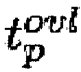


- Hovl ist damit eine Linearkombination der Potenzen


- Der Verlauf der Gütefunktionskomponente Hovl in Abhängigkeit der Basis

Fig. 3 dargestellten Verlauf der Gütefunktionskomponente Hb. Die vorstehend bezüglich des Verlaufs des Diagramms gemäßFig. 3 gemachten Erläuterungen lassen sich daher auf den Verlauf von Hovl übertragen. - Im Folgenden wird ein Ausführungsbeispiel für die Gütefunktionskomponente Hx beschrieben. Die Stellwege xi der Manipulatoren Ms weisen untere Grenzwerte


- Wie bereits vorstehend erläutert, bezeichnet ein einzelnes xi einen Freiheitsgrad eines Manipulators Ms, wobei die einzelnen Manipulatoren einen oder mehrere Freiheitsgrade aufweisen können. Verwendet man die folgenden Ersetzungen:



- Die die Grenzwerte der Manipulatoren betreffende Gütefunktionskomponente Hx lautet dann:

- Hierbei geht die Summe der Zählvariablen i über alle Freiheitsgrade aller Manipulatoren Ms. Die vom Nutzer frei wählbaren Parameter sind


- Hx ist damit eine Linearkombination der Potenzen


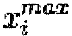


- Der Verlauf der Gütefunktionskomponente Hx in Abhängigkeit der Basis

Fig. 3 dargestellten Verlauf der Gütefunktionskomponente Hb. Die vorstehend bezüglich des Verlaufs des Diagramms gemäßFig. 3 gemachten Erläuterungen lassen sich daher auf den Verlauf von Hx übertragen. - Im Folgenden wird ein Ausführungsbeispiel für die Gütefunktionskomponente Hica beschrieben. Wie bereits vorstehend erwähnt, beschreibt Hica Randbedingungen der mittels der Nachbearbeitungseinrichtung 36 an einzelnen optischen Elementen, wie den optischen Elementen L1 bis L4 des Projektionsobjektivs 16 gemäß
Fig. 1 , vorzunehmenden ICA-Abtragungen. Die mittels ICA-Abtragungen in einem optischen Element erzeugten Profile FL (xK,yK ) können wie folgt als Summe von n Basisfunktionen

- Hierbei bezeichnen xK und yK die kartesischen x- und y-Koordinaten auf einem betreffenden optischen Element L. Die Basisfunktionen


- Eine Peak-to-Valley Funktion PVL der ICA-Abtragungen wird wie folgt definiert

- Die Grenzwertbedingung für das resultierende Profil FL(xK,yK) lautet:

- Hierbei ist der Zielwert


- Die die Grenzwerte von ICA-Abtragungen betreffende Gütefunktionskomponente Hica lautet wie folgt:

- Die Summe über den Index L geht über alle optische Elemente, bei denen ICA-Abtragungen vorgenommen werden und die Summe über k geht über alle zur Beschreibung des betreffenden optischen Elements verwendeten Basisfunktonen. Weiterhin bezeichnen


- Hica ist damit eine Linearkombination der Potenzen


- Der Verlauf der Gütefunktionskomponente Hica in Abhängigkeit der Basis

Fig. 3 dargestellten Verlauf der Gütefunktionskomponente Hb im Wesentlichen darin, dass die Annäherung an die bei -1 und +1 angeordneten vertikalen Linien weniger steil erfolgt und die Linien stärker überschritten werden. - Im Folgenden wird ein Ausführungsbeispiel für die Gütefunktionskomponente Hrms beschrieben. Dazu werden gruppierte RMS-Werte RMSr wie folgt definiert:

- Hierbei ist r eine Zählvariable des gruppierten RMS-Werts RMSr. Die Gruppierung erfolgt beispielsweise durch Einordung der entsprechenden Zernike-Koeffizienten bj in die Kategorien "sphärische Aberrationen", "Koma", "Astigmatismus", etc. Die Summe über j ist eine Summe über die Zernike-Ordnungen,

- Die Bedingungen für die RMS-Werte lauten:

- Hierbei ist


- Hierbei bezeichnen


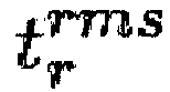

- Hrms ist damit eine Linearkombination der Potenzen


- Der Verlauf der Gütefunktionskomponente Hrms in Abhängigkeit der Basis

Fig. 3 dargestellten Verlauf der Gütefunktionskomponente Hb. Die vorstehend bezüglich des Verlaufs des Diagramms gemäßFig. 3 gemachten Erläuterungen lassen sich daher auf den Verlauf von Hrms übertragen. - Die Parameter


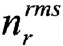
-
Fig. 2 zeigt eine erfindungsgemäße Ausführungsform einer Projektionsbelichtungsanlage 50 für die Mikrolithographie. Die vorliegende Ausführungsform ist zum Betrieb im EUV-Wellenlängenbereich ausgelegt. Aufgrund dieser Betriebswellenlänge sind alle optischen Elemente als Spiegel ausgeführt. Die Erfindung ist jedoch nicht auf Projektionsbelichtungsanlagen im EUV-Wellenlängenbereich begrenzt. Weitere erfindungsgemäße Ausführungsformen sind beispielsweise auf Betriebswellenlängen im UV-Bereich, wie beispielsweise 365 nm, 248 nm oder 193 nm ausgelegt. In diesem Fall sind zumindest einige der optischen Elemente als herkömmliche Transmissionslinsen konfiguriert. - Die Projektionsbelichtungsanlage 10 gemäß
Fig. 2 umfasst eine Belichtungsstrahlungsquelle 52 zur Erzeugung von Belichtungsstrahlung 54. Im vorliegenden Fall ist die Belichtungsstrahlungsquelle 52 als EUV-Quelle ausgeführt und kann beispielsweise eine Plasmastrahlungsquelle umfassen. Die Belichtungsstrahlung 54 durchläuft zunächst eine Beleuchtungsoptik 56 und wird von dieser auf eine Maske 58 gelenkt. Die Beleuchtungsoptik 56 ist dazu konfiguriert, unter-schiedliche Winkelverteilungen der auf die Maske 58 auftreffenden Belichtungsstrahlung 54 zu erzeugen. Abhängig von einer vom Benutzer gewünschten Beleuchtungseinstellung, auch "Beleuchtungssetting" genannt, konfiguriert die Beleuchtungsoptik 56 die Winkelverteilung der auf die Maske 58 auftreffenden Belichtungsstrahlung 54. Beispiele für wählbare Beleuchtungseinstellungen umfassen eine sogenannte Dipol-Beleuchtung, annulare Beleuchtung und Quadrupolbeleuchtung. - Die Maske 58 weist Maskenstrukturen zur Abbildung auf ein Substrat 64 in Gestalt eines Wafers auf und ist auf einer Maskenverschiebebühne 60 verschiebbar gelagert. Die Maske 58 kann, wie in
Fig. 2 dargestellt, als Reflexionsmaske ausgeführt sein oder alternativ, insbesondere für die UV-Lithographie, auch als Transmissionsmaske konfiguriert sein. Die Belichtungsstrahlung 54 wird in der Ausführungsform gemäßFig. 2 an der Maske 58 reflektiert und durchläuft daraufhin das bereits unter Bezugnahme auf die Justieranlage 10 gemäßFig. 1 beschriebene Projektionsobjektiv 16. Das Projektionsobjektiv dient dazu, die Maskenstrukturen der Maske 58 auf das Substrat 64 abzubilden. Die Belichtungsstrahlung 54 wird innerhalb des Projektionsobjektivs 16 mittels einer Vielzahl von optischen Elementen, vorliegend in Gestalt von Spiegeln, geführt. Das Substrat 64 ist auf einer Substratverschiebebühne 66 verschiebbar gelagert. Die Projektionsbelichtungsanlage 50 kann als sogenannter Scanner oder als sogenannter Stepper ausgeführt sein. - Im Fall der Ausführung als Scanner, auch Step- und Scan-Projektionsbelichtungsanlage genannt, werden bei jeder Abbildung der Maske 58 auf das Substrat 64, d.h. bei jeder Belichtung eines Feldes auf dem Substrat 64, die Maskenverschiebebühne 60 sowie die Substratverschiebebühne 66 in gegenläufiger Richtung bewegt. Wie in
Fig. 2 gezeigt, bewegt sich dabei beispielsweise die Maskenverschiebebühne 60 in eine nach links weisende Scanrichtung 62 und die Substratverschiebebühne in eine nach rechts weisende Scanrichtung 68. Die vorstehend im Zusammenhang mit der Beschreibung der Gütefunktionskomponente Hf erläuterten Fading-Aberrationen sind auf die Scanbewegungen während der Feldbelichtung eines derartigen Scanners zurückzuführen. - Die Projektionsbelichtungsanlage 50 umfasst weiterhin eine zentrale Steuerungseinrichtung 72 zur Steuerung des Belichtungsvorganges, einschließlich der Maskenverschiebebühne 60 sowie der Substratverschiebebühne 66. Die Projektionsbelichtungsanlage 10 umfasst weiterhin eine Steuerungsvorrichtung 114 zur Steuerung der Manipulatoren M1 bis M4. Die Steuerungsvorrichtung 114 wiederum umfasst einen Zustandsgeber 80 sowie einen Stellwegsermittler 86. Der Zustandsgeber 80 übergibt aktuelle Zustandscharakterisierungen 34a des Projektionsobjektivs 16 an den Stellwegsermittler 86, welcher daraus einen Stellwegbefehl 138 erzeugt. Der Stellwegbefehl 138 umfasst Stellwege xi, im gezeigten Fall die Stellwege x1, x2, x3 sowie x4. Diese Stellwege dienen der Steuerung der Manipulatoren M1 bis M4, wie vorstehend in Bezug auf die Justieranlage 10 gemäß
Fig. 1 näher beschrieben. - Der vom Stellwegsermittler 86 erzeugte Stellwegbefehl 138 umfasst von den Manipulatoren M1 bis M4 auszuführende Veränderungen in Form von Stellwegen xi entsprechender Zustandsgrößen der optischen Elemente L1 bis L4. Die ermittelten Stellwege xi werden den einzelnen Manipulatoren M1 bis M4 über Stellwegsignale übermittelt und geben diesen jeweilige auszuführende Korrekturstellwege vor. Diese definieren entsprechende Verlagerungen der zugeordneten optischen Elemente L1 bis L4 zur Korrektur aufgetretener Wellenfrontfehler des Projektionsobjektivs 16. Zur Ermittlung der Stellwege xi erhält der Stellwegsermittler 86 von Zustandsgeber 80, insbesondere während der Ausführung des Belichtungsvorganges, jeweils aktualisierte Zustandscharakterisierungen 34a in Gestalt von die Wellenfront charakterisierenden Zernike-Koeffizienten bj.
- Der Stellwegsermittler 86 erzeugt gemäß einer Ausführungsform während der Belichtung eines Substrats 64 mehrfach aktualisierte Stellwege xi. Gemäß einer Ausführungsform weist der Zustandsgeber 80 einen Speicher 82 sowie eine Simulationseinrichtung 84 auf. Im Speicher 82 werden Zustandscharakterisierungen 34 in Gestalt von Aberrationsparametern abgespeichert, die mittels einer Wellenfrontmessung an dem Projektionsobjektiv 16 ermittelt worden sind. Diese Messergebnisse können mittels einer externen Wellenfrontmessvorrichtung, wie der in Bezug auf
Fig. 1 beschriebenen Messvorrichtung 12, erhoben werden. Alternativ können die Zustandscharakterisierungen 34 aber auch von einer in der Substratverschiebebühne 66 integrierten Wellenfrontmesseinrichtung 70 gemessen werden. Eine derartige Messung kann etwa regelmäßig nach jeder Belichtung eines Wafers oder jeweils nach Belichtung eines kompletten Wafersatzes erfolgen. Alternativ kann anstatt einer Messung auch eine Simulation bzw. eine Kombination aus Simulation und reduzierter Messung vorgenommen werden. - Die im Speicher 82 abgelegten Messwerte der Zustandscharakterisierung 34 in Gestalt von Aberrationsparametern in Form von Zernike-Koeffizienten werden ggf. von der Simulationseinrichtung 84 an jeweilige aktualisierte Verhältnisse während des Belichtungsvorganges angepasst. Gemäß einer Ausführungsvariante wird der Simulationseinrichtung 84 dazu regelmäßig von der zentralen Steuerungseinrichtung 72 die aktuelle Bestrahlungsintensität 74 übermittelt. Die Simulationseinrichtung 84 berechnet daraus unter Zugrundelegung der jeweiligen Beleuchtungseinstellung aufgrund von Linsenaufheizung bewirkte Änderungen in den Aberrationsparametern. Weiterhin erhält die Simulationseinrichtung laufend Messwerte eines den Umgebungsdruck der Projektionsbelichtungsanlage 10 überwachenden Drucksensors 76. Auswirkungen von Veränderungen im Umgebungsdruck auf die Aberrationsparameter werden von der Simulationseinrichtung 84 berücksichtigt.
- Die Steuerungsvorrichtung 114 der Projektionsbelichtungsanlage 50 gemäß
Fig. 2 unterscheidet sich von der Steuerungseinrichtung 14 der Justieranlage 10 gemäßFig. 1 dadurch, dass die Steuerungsvorrichtung 114 mittels des Zustandsgebers 80 die von einer Wellenfrontmesseinrichtung gemessene Zustandscharakterisierung 34 unter Verwendung der aktuellen Beleuchtungsintensität 74 in eine aktuelle Zustandscharakterisierung 34a umwandelt. Die Funktion des Stellwegsermittlers 86 der Steuerungsvorrichtung 114 entspricht der Funktion der Steuerungseinrichtung 14, allerdings mit der Einschränkung, dass der von der Steuerungsvorrichtung 114 erzeugte Stellwegsbefehl 138 lediglich den Stellwegvektor x mit den Stellwegen xi der Manipulatoren, nicht jedoch den Stellwegvektor xL zur Steuerung der ICA-Nachbearbeitungseinrichtung 36 umfasst. - Die vorstehende Beschreibung beispielhafter Ausführungsformen ist exemplarisch zu verstehen. Die damit erfolgte Offenbarung ermöglicht es dem Fachmann einerseits, die vorliegende Erfindung und die damit verbundenen Vorteile zu verstehen, und umfasst andererseits im Verständnis des Fachmanns auch offensichtliche Abänderungen und Modifikationen der beschriebenen Strukturen und Verfahren. Daher sollen alle derartigen Abänderungen und Modifikationen, insoweit sie in den Rahmen der Erfindung gemäß der Definition in den beigefügten Ansprüchen fallen, sowie Äquivalente vom Schutz der Ansprüche abgedeckt sein.
-
- 10
- Justieranlage
- 12
- Messvorrichtung
- 14
- Steuerungsvorrichtung
- 16
- Projektionsobjektiv
- 18
- Beleuchtungseinrichtung
- 20
- Messstrahlung
- 22
- Messmaske
- 24
- Objektebene
- 26
- Sensorelement
- 28
- Bildebene
- 30
- Detektor
- 32
- Auswerteeinrichtung
- 34
- Zustandscharakterisierung
- 34a
- aktuelle Zustandscharakterisierung
- 36
- Nachbearbeitungseinrichtung
- 38
- Stellwegbefehl
- 40
- Kippachse
- 50
- Projektionsbelichtungsanlage
- 52
- Belichtungsstrahlungsquelle
- 54
- Belichtungsstrahlung
- 56
- Beleuchtungsoptik
- 58
- Maske
- 60
- Maskenverschiebebühne
- 62
- Scanrichtung der Maskenverschiebebühne
- 64
- Substrat
- 66
- Substratverschiebebühne
- 68
- Scanrichtung der Substratverschiebebühne
- 70
- Wellenfrontmesseinrichtung
- 72
- zentrale Steuerungseinrichtung
- 74
- aktuelle Bestrahlungsintensität
- 76
- Drucksensor
- 80
- Zustandsgeber
- 82
- Speicher
- 84
- Simulationseinrichtung
- 86
- Stellwegsermittler
- 114
- Steuerungsvorrichtung
- 138
- Stellwegbefehl
- Die Ansprüche der Erfindung folgen nachstehend.
M1 - M4 Manipulatoren
b Zustandsvektor
xi Stellwege für Manipulatoren

Claims (15)
- Steuerungsvorrichtung (14; 114) zur Steuerung mindestens eines Manipulators (M1, M2, M3, M4; 36) eines Projektionsobjektivs (16) für die Mikrolithographie durch Generierung eines Stellwegbefehls (38; 138), welcher eine vorzunehmende Veränderung einer optischen Wirkung mindestens eines optischen Elements (L1, L2, L3, L4) des Projektionsobjektivs durch Manipulation einer Eigenschaft des optischen Elements mittels des mindestens einen Manipulators entlang eines Stellweges definiert,
wobei die Steuerungsvorrichtung dazu konfiguriert ist, aus einer Zustandscharakterisierung (34) des Projektionsobjektivs den Stellwegbefehl für den mindestens einen Manipulator durch Optimierung einer Gütefunktion zu generieren, wobei:die Gütefunktion eine Linearkombination mindestens zweier Potenzen umfasst,eine die Manipulation der Eigenschaft des optischen Elements (L1, L2, L3, L4) definierende Einstellung des mindestens einen Manipulators (M1, M2, M3, M4; 36) mittels einer Stellwegvariablen dargestellt wird und die jeweilige Basis der mindestens zwei Potenzen eine Funktion der Stellwegvariablen (xi, die Exponenten der mindestens zwei Potenzen unterschiedliche Werte aufweisen.
 - Steuerungsvorrichtung nach Anspruch 1,
bei der die mindestens zwei Potenzen unterschiedliche Basen aufweisen. - Steuerungsvorrichtung nach Anspruch 1 oder 2,
bei der die Exponenten der mindestens zwei Potenzen Werte von jeweils größer oder gleich zwei aufweisen. - Steuerungsvorrichtung nach einem der vorausgehenden Ansprüche,
bei der die jeweilige Basis der mindestens zwei Potenzen jeweils einen Quotienten enthält, dessen Zähler einen die Funktion der Stellwegvariablen enthaltenden Term umfasst und dessen Nenner einen Zielwert für den Term des Zählers sowie einen Gewichtungsfaktor für den Zielwert aufweist. - Steuerungsvorrichtung nach einem der vorausgehenden Ansprüche,
bei der eine Differenz der Werte der beiden Exponenten mindestens fünf beträgt. - Steuerungsvorrichtung nach einem der vorausgehenden Ansprüche,
welche zur Steuerung mehrerer Manipulatoren konfiguriert ist, die Zustandscharakterisierung (34) mehrere durch einen Zustandsvektor (b) charakterisierte Zustandsparameter (bj) umfasst, und jeder der Potenzen eine Sensitivitätsmatrix (M) umfasst, welche einen Zusammenhang zwischen den Stellwegen der Manipulatoren und dem Zustandsvektor definiert. - Steuerungsvorrichtung nach einem der vorausgehenden Ansprüche,
bei der eine der Potenzen einen Term umfasst, welcher einen Bildfehler (bj) des Projektionsobjektivs (16) beschreibt. - Steuerungsvorrichtung nach einem der vorausgehenden Ansprüche,
bei der eine der Potenzen einen Term umfasst, welcher eine Fading-Aberration einer Step- und Scan Projektionsbelichtungsanlage (50) für die Mikrolithographie beschreibt. - Steuerungsvorrichtung nach einem der vorausgehenden Ansprüche,
bei der eine der Potenzen einen Term umfasst, welcher einen quadratischen Mittelwert (RMSr) einer Auswahl von Bildfehlern des Projektionsobjektivs beschreibt. - Steuerungsvorrichtung nach einem der vorausgehenden Ansprüche,
bei der eine der Potenzen einen Term umfasst, welcher einen reinen Overlay-Fehler beschreibt. - Steuerungsvorrichtung nach einem der vorausgehenden Ansprüche,
bei der eine der Potenzen einen Term umfasst, welcher einen mittels mechanischer Nachbearbeitung eines optischen Elements (L1, L2, L3, L4) des Projektionsobjektivs korrigierbaren Fehler beschreibt. - Justieranlage (10) zur Justierung eines Projektionsobjektivs (16) für die Mikrolithographie,
mit einer Messvorrichtung (12) zur Ermittlung der Zustandscharakterisierung (34) des Projektionsobjektivs, sowie einer Steuerungsvorrichtung (14) nach einem der vorausgehenden Ansprüche zur Generierung des Stellwegbefehls (38) aus der Zustandscharakterisierung. - Justieranlage nach Anspruch 12,
bei der die Messvorrichtung als Wellenfrontmesseinrichtung konfiguriert ist. - Projektionsbelichtungsanlage (50) für die Mikrolithographie mit:- einem Projektionsobjektiv (16) zum Abbilden von Maskenstrukturen,- mindestens einem Manipulator (M1, M2, M3, M4), welcher dazu konfiguriert ist, eine optische Wirkung mindestens eines optischen Elements (L1, L2, L3, L4) des Projektionsobjektivs durch Manipulation einer Eigenschaft des optischen Elements entlang eines Stellweges zu verändern, sowie- einer Steuerungsvorrichtung (114) nach einem der Ansprüche 1 bis 12 zur Steuerung des mindestens einen Manipulators.
- Verfahren zum Steuern mindestens eines Manipulators (M1, M2, M3, M4; 36) eines Projektionsobjektivs (16) für die Mikrolithographie mit den Schritten:- Generieren eines Stellwegbefehls (38; 138) für den mindestens einen Manipulator durch Ausführen einer Optimierung einer Gütefunktion, wobei:die Gütefunktion eine Linearkombination mindestens zweier Potenzen umfasst,eine die Manipulation der Eigenschaft des optischen Elements definierende Einstellung des mindestens einen Manipulators mittels einer Stellwegvariablen (xi,
 die Exponenten der mindestens zwei Potenzen unterschiedliche Werte aufweisen, sowie- Verändern einer optischen Wirkung mindestens eines optischen Elements des Projektionsobjektivs (16) durch Manipulation einer Eigenschaft des optischen Elements mittels des mindestens einen Manipulators entlang eines durch den generierten Stellwegbefehl (38; 138) definierten Stellweges.
Applications Claiming Priority (1)
| Application Number | Priority Date | Filing Date | Title |
|---|---|---|---|
| DE102015206448.4A DE102015206448B4 (de) | 2015-04-10 | 2015-04-10 | Steuerungsvorrichtung zur Steuerung mindestens eines Manipulators eines Projektionsobjektives, Justieranlage und Verfahren zum Steuern mindestens eines Manipulators |
Publications (3)
| Publication Number | Publication Date |
|---|---|
| EP3079016A2 true EP3079016A2 (de) | 2016-10-12 |
| EP3079016A3 EP3079016A3 (de) | 2016-12-07 |
| EP3079016B1 EP3079016B1 (de) | 2022-06-29 |
Family
ID=55699292
Family Applications (1)
| Application Number | Title | Priority Date | Filing Date |
|---|---|---|---|
| EP16000776.1A Active EP3079016B1 (de) | 2015-04-10 | 2016-04-05 | Steuerungsvorrichtung zur steuerung mindestens eines manipulators eines projektionsobjektivs |
Country Status (4)
| Country | Link |
|---|---|
| US (1) | US9823578B2 (de) |
| EP (1) | EP3079016B1 (de) |
| JP (1) | JP6333304B2 (de) |
| DE (1) | DE102015206448B4 (de) |
Families Citing this family (13)
| Publication number | Priority date | Publication date | Assignee | Title |
|---|---|---|---|---|
| KR101668984B1 (ko) * | 2013-09-14 | 2016-10-24 | 칼 짜이스 에스엠티 게엠베하 | 마이크로리소그래피 투영 장치의 동작 방법 |
| DE102015209051B4 (de) * | 2015-05-18 | 2018-08-30 | Carl Zeiss Smt Gmbh | Projektionsobjektiv mit Wellenfrontmanipulator sowie Projektionsbelichtungsverfahren und Projektionsbelichtungsanlage |
| KR102652685B1 (ko) | 2018-12-31 | 2024-04-01 | 에이에스엠엘 네델란즈 비.브이. | 패턴화 장치의 광학적 특성의 성분의 서브세트의 결정 |
| DE102019200218B3 (de) | 2019-01-10 | 2020-06-25 | Carl Zeiss Smt Gmbh | Steuerungsvorrichtung, Justieranordnung und Verfahren zur Steuerung eines Manipulators bezüglich einer Projektionsbelichtungsanlage für die Mikrolithographie |
| CN114667488B (zh) * | 2019-09-10 | 2025-07-22 | Asml荷兰有限公司 | 光刻过程的子场控制和相关联设备 |
| DE102020210567B3 (de) | 2020-08-20 | 2021-11-11 | Carl Zeiss Smt Gmbh | Steuerungsvorrichtung und -verfahren zur Steuerung von Manipulatoren für ein Projektionsobjektiv, Justieranlage, Projektionsobjektiv und Projektionsbelichtungsanlage |
| CN112558318B (zh) * | 2020-11-30 | 2021-09-28 | 中国科学院长春光学精密机械与物理研究所 | 大口径光学元件辅助装调方法 |
| DE102022201978A1 (de) | 2021-05-19 | 2022-11-24 | Carl Zeiss Smt Gmbh | Steuerung für einen Manipulator eines Projektionsobjektivs |
| DE102022004902A1 (de) * | 2022-12-23 | 2024-07-04 | Carl Zeiss Smt Gmbh | Projektionsbelichtungsanlage mit manipulatoren |
| DE102023111478A1 (de) * | 2023-05-03 | 2024-11-07 | Asml Netherlands B.V. | Verfahren zum auswerten von messwerten einer aberration eines projektionsobjektivs |
| DE102023207890A1 (de) | 2023-08-17 | 2024-07-25 | Carl Zeiss Smt Gmbh | Verfahren zur Justage eines Objektivs |
| DE102024104118A1 (de) | 2024-02-14 | 2025-08-14 | Carl Zeiss Smt Gmbh | Verfahren zum Herstellen eines optischen Abbildungssystems für eine Mikrolithographie-Anlage |
| DE102025107128A1 (de) * | 2025-02-25 | 2026-01-22 | Carl Zeiss Smt Gmbh | Verfahren zum Bestimmen eines Justagerezepts für ein optisches System der Mikrolithographie |
Citations (2)
| Publication number | Priority date | Publication date | Assignee | Title |
|---|---|---|---|---|
| WO2010034674A1 (en) | 2008-09-25 | 2010-04-01 | Carl Zeiss Smt Ag | Projection exposure apparatus with optimized adjustment possibility |
| US20130188246A1 (en) | 2010-09-30 | 2013-07-25 | Carl Zeiss Smt Gmbh | Imaging Optical System for Microlithography |
Family Cites Families (10)
| Publication number | Priority date | Publication date | Assignee | Title |
|---|---|---|---|---|
| US6493374B1 (en) | 1999-09-03 | 2002-12-10 | Cymer, Inc. | Smart laser with fast deformable grating |
| DE10143385C2 (de) | 2001-09-05 | 2003-07-17 | Zeiss Carl | Projektionsbelichtungsanlage |
| AU2003229725A1 (en) | 2003-04-24 | 2004-11-19 | Carl Zeiss Smt Ag | Projection optical system |
| EP1927890A1 (de) | 2006-11-30 | 2008-06-04 | Carl Zeiss SMT AG | Verfahren zur Herstellung eines Projektionsobjektivs und mit diesem Verfahren hergestelltes Projektionsobjektiv |
| JP5559543B2 (ja) | 2006-11-30 | 2014-07-23 | カール・ツァイス・エスエムティー・ゲーエムベーハー | 投影対物器械を製造する方法及びこの方法によって製造される投影対物器械 |
| US7307690B1 (en) | 2006-12-21 | 2007-12-11 | Asml Netherlands B.V. | Device manufacturing method, computer program product and lithographic apparatus |
| EP2392970A3 (de) | 2010-02-19 | 2017-08-23 | ASML Netherlands BV | Verfahren und Vorrichtung zur Steuerung eines lithografischen Gerätes |
| DE102012205096B3 (de) | 2012-03-29 | 2013-08-29 | Carl Zeiss Smt Gmbh | Projektionsbelichtungsanlage mit mindestens einem Manipulator |
| WO2014000763A1 (en) | 2012-06-25 | 2014-01-03 | Carl Zeiss Smt Gmbh | Method for designing an illumination optics and illumination optics |
| DE102013225381A1 (de) * | 2013-12-10 | 2014-11-06 | Carl Zeiss Smt Gmbh | Verfahren zur Kalibrierung eines Manipulators |
-
2015
- 2015-04-10 DE DE102015206448.4A patent/DE102015206448B4/de active Active
-
2016
- 2016-03-25 US US15/081,074 patent/US9823578B2/en active Active
- 2016-04-05 EP EP16000776.1A patent/EP3079016B1/de active Active
- 2016-04-08 JP JP2016078086A patent/JP6333304B2/ja active Active
Patent Citations (2)
| Publication number | Priority date | Publication date | Assignee | Title |
|---|---|---|---|---|
| WO2010034674A1 (en) | 2008-09-25 | 2010-04-01 | Carl Zeiss Smt Ag | Projection exposure apparatus with optimized adjustment possibility |
| US20130188246A1 (en) | 2010-09-30 | 2013-07-25 | Carl Zeiss Smt Gmbh | Imaging Optical System for Microlithography |
Non-Patent Citations (2)
| Title |
|---|
| "Optical Shop Testing", 1992, JOHN WILEY & SONS, INC., article "Kapitel 13.2.3" |
| H. GROSS: "Handbook of Optical Systems", vol. 2, 2005, WILEY-VCH VERLAG GMBH & CO. KGAA, pages: 215 |
Also Published As
| Publication number | Publication date |
|---|---|
| EP3079016A3 (de) | 2016-12-07 |
| JP2016200818A (ja) | 2016-12-01 |
| EP3079016B1 (de) | 2022-06-29 |
| JP6333304B2 (ja) | 2018-05-30 |
| US9823578B2 (en) | 2017-11-21 |
| DE102015206448A1 (de) | 2016-10-13 |
| US20160299436A1 (en) | 2016-10-13 |
| DE102015206448B4 (de) | 2018-06-21 |
Similar Documents
| Publication | Publication Date | Title |
|---|---|---|
| DE102015206448B4 (de) | Steuerungsvorrichtung zur Steuerung mindestens eines Manipulators eines Projektionsobjektives, Justieranlage und Verfahren zum Steuern mindestens eines Manipulators | |
| DE102012205096B3 (de) | Projektionsbelichtungsanlage mit mindestens einem Manipulator | |
| DE102019200218B3 (de) | Steuerungsvorrichtung, Justieranordnung und Verfahren zur Steuerung eines Manipulators bezüglich einer Projektionsbelichtungsanlage für die Mikrolithographie | |
| DE102020210567B3 (de) | Steuerungsvorrichtung und -verfahren zur Steuerung von Manipulatoren für ein Projektionsobjektiv, Justieranlage, Projektionsobjektiv und Projektionsbelichtungsanlage | |
| DE102004035595B4 (de) | Verfahren zur Justage eines Projektionsobjektives | |
| DE102015220537A1 (de) | Projektionsbelichtungsanlage mit mindestens einem Manipulator | |
| DE102010029651A1 (de) | Verfahren zum Betrieb einer Projektionsbelichtungsanlage für die Mikrolithographie mit Korrektur von durch rigorose Effekte der Maske induzierten Abbildungsfehlern | |
| DE102011080437A1 (de) | Abbildendes optisches System für die Mikrolithographie | |
| DE102008042356A1 (de) | Projektionsbelichtungsanlage mit optimierter Justagemöglichkeit | |
| DE102013001948B4 (de) | Oberflächenformmessverfahren und -vorrichtung, Computerprogramm, computerlesbares nichtflüchtiges Speichermedium sowie Fertigungsverfahren eines optischen Elements | |
| DE102014223750A1 (de) | Projektionsbelichtungsanlage mit mindestens einem Manipulator | |
| DE102010062763A1 (de) | Verfahren zum Vermessen eines optischen Systems | |
| DE102015222377B4 (de) | Projektionsbelichtungsanlage mit einem Manipulatorsystem | |
| DE102017209440A1 (de) | Projektionsbelichtungsverfahren und Projektionsbelichtungsanlage für die Mikrolithografie | |
| DE102017210164B4 (de) | Verfahren zur Justage eines Abbildungsverhaltens eines Projektionsobjektivs und Justageanlage | |
| DE102022211459A1 (de) | Projektionsbelichtungsanlage mit einem Manipulatorsystem | |
| DE102012202536A1 (de) | Projektionsbelichtungsverfahren und Projektionsbelichtungsanlage für die Mikrolithographie | |
| DE102006039895A1 (de) | Verfahren zur Korrektur von durch Intensitätsverteilungen in optischen Systemen erzeugten Abbildungsveränderungen sowie entsprechendes optisches System | |
| WO2021160583A1 (de) | Projektionsbelichtungsanlage mit einem thermischen manipulator | |
| DE102010041528A1 (de) | Projektionsbelichtungsanlage mit optimierter Justagemöglichkeit | |
| DE102012212758A1 (de) | Systemkorrektur aus langen Zeitskalen | |
| EP3359928A2 (de) | Verfahren und vorrichtung zur strahlanalyse | |
| DE102016205987B4 (de) | Projektionsbelichtungsanlage mit mindestens einem Manipulator und Verfahren zum Steuern einer Projektionsbelichtungsanlage | |
| DE102022004902A1 (de) | Projektionsbelichtungsanlage mit manipulatoren | |
| WO2024227706A2 (de) | Verfahren zum auswerten von messwerten einer aberration eines projektionsobjektivs |
Legal Events
| Date | Code | Title | Description |
|---|---|---|---|
| PUAI | Public reference made under article 153(3) epc to a published international application that has entered the european phase |
Free format text: ORIGINAL CODE: 0009012 |
|
| AK | Designated contracting states |
Kind code of ref document: A2 Designated state(s): AL AT BE BG CH CY CZ DE DK EE ES FI FR GB GR HR HU IE IS IT LI LT LU LV MC MK MT NL NO PL PT RO RS SE SI SK SM TR |
|
| AX | Request for extension of the european patent |
Extension state: BA ME |
|
| PUAL | Search report despatched |
Free format text: ORIGINAL CODE: 0009013 |
|
| AK | Designated contracting states |
Kind code of ref document: A3 Designated state(s): AL AT BE BG CH CY CZ DE DK EE ES FI FR GB GR HR HU IE IS IT LI LT LU LV MC MK MT NL NO PL PT RO RS SE SI SK SM TR |
|
| AX | Request for extension of the european patent |
Extension state: BA ME |
|
| RIC1 | Information provided on ipc code assigned before grant |
Ipc: G03F 7/20 20060101AFI20161031BHEP Ipc: G02B 27/00 20060101ALI20161031BHEP Ipc: G02B 7/02 20060101ALI20161031BHEP |
|
| STAA | Information on the status of an ep patent application or granted ep patent |
Free format text: STATUS: REQUEST FOR EXAMINATION WAS MADE |
|
| 17P | Request for examination filed |
Effective date: 20170607 |
|
| RBV | Designated contracting states (corrected) |
Designated state(s): AL AT BE BG CH CY CZ DE DK EE ES FI FR GB GR HR HU IE IS IT LI LT LU LV MC MK MT NL NO PL PT RO RS SE SI SK SM TR |
|
| GRAP | Despatch of communication of intention to grant a patent |
Free format text: ORIGINAL CODE: EPIDOSNIGR1 |
|
| STAA | Information on the status of an ep patent application or granted ep patent |
Free format text: STATUS: GRANT OF PATENT IS INTENDED |
|
| INTG | Intention to grant announced |
Effective date: 20210629 |
|
| GRAJ | Information related to disapproval of communication of intention to grant by the applicant or resumption of examination proceedings by the epo deleted |
Free format text: ORIGINAL CODE: EPIDOSDIGR1 |
|
| STAA | Information on the status of an ep patent application or granted ep patent |
Free format text: STATUS: REQUEST FOR EXAMINATION WAS MADE |
|
| INTC | Intention to grant announced (deleted) | ||
| GRAP | Despatch of communication of intention to grant a patent |
Free format text: ORIGINAL CODE: EPIDOSNIGR1 |
|
| STAA | Information on the status of an ep patent application or granted ep patent |
Free format text: STATUS: GRANT OF PATENT IS INTENDED |
|
| GRAJ | Information related to disapproval of communication of intention to grant by the applicant or resumption of examination proceedings by the epo deleted |
Free format text: ORIGINAL CODE: EPIDOSDIGR1 |
|
| STAA | Information on the status of an ep patent application or granted ep patent |
Free format text: STATUS: REQUEST FOR EXAMINATION WAS MADE |
|
| INTG | Intention to grant announced |
Effective date: 20211103 |
|
| INTC | Intention to grant announced (deleted) | ||
| GRAP | Despatch of communication of intention to grant a patent |
Free format text: ORIGINAL CODE: EPIDOSNIGR1 |
|
| STAA | Information on the status of an ep patent application or granted ep patent |
Free format text: STATUS: GRANT OF PATENT IS INTENDED |
|
| INTG | Intention to grant announced |
Effective date: 20220120 |
|
| GRAS | Grant fee paid |
Free format text: ORIGINAL CODE: EPIDOSNIGR3 |
|
| GRAA | (expected) grant |
Free format text: ORIGINAL CODE: 0009210 |
|
| STAA | Information on the status of an ep patent application or granted ep patent |
Free format text: STATUS: THE PATENT HAS BEEN GRANTED |
|
| AK | Designated contracting states |
Kind code of ref document: B1 Designated state(s): AL AT BE BG CH CY CZ DE DK EE ES FI FR GB GR HR HU IE IS IT LI LT LU LV MC MK MT NL NO PL PT RO RS SE SI SK SM TR |
|
| REG | Reference to a national code |
Ref country code: GB Ref legal event code: FG4D Free format text: NOT ENGLISH |
|
| REG | Reference to a national code |
Ref country code: CH Ref legal event code: EP |
|
| REG | Reference to a national code |
Ref country code: DE Ref legal event code: R096 Ref document number: 502016015000 Country of ref document: DE |
|
| REG | Reference to a national code |
Ref country code: AT Ref legal event code: REF Ref document number: 1501735 Country of ref document: AT Kind code of ref document: T Effective date: 20220715 |
|
| REG | Reference to a national code |
Ref country code: IE Ref legal event code: FG4D Free format text: LANGUAGE OF EP DOCUMENT: GERMAN |
|
| REG | Reference to a national code |
Ref country code: NL Ref legal event code: FP |
|
| REG | Reference to a national code |
Ref country code: LT Ref legal event code: MG9D |
|
| PG25 | Lapsed in a contracting state [announced via postgrant information from national office to epo] |
Ref country code: SE Free format text: LAPSE BECAUSE OF FAILURE TO SUBMIT A TRANSLATION OF THE DESCRIPTION OR TO PAY THE FEE WITHIN THE PRESCRIBED TIME-LIMIT Effective date: 20220629 Ref country code: NO Free format text: LAPSE BECAUSE OF FAILURE TO SUBMIT A TRANSLATION OF THE DESCRIPTION OR TO PAY THE FEE WITHIN THE PRESCRIBED TIME-LIMIT Effective date: 20220929 Ref country code: LT Free format text: LAPSE BECAUSE OF FAILURE TO SUBMIT A TRANSLATION OF THE DESCRIPTION OR TO PAY THE FEE WITHIN THE PRESCRIBED TIME-LIMIT Effective date: 20220629 Ref country code: HR Free format text: LAPSE BECAUSE OF FAILURE TO SUBMIT A TRANSLATION OF THE DESCRIPTION OR TO PAY THE FEE WITHIN THE PRESCRIBED TIME-LIMIT Effective date: 20220629 Ref country code: GR Free format text: LAPSE BECAUSE OF FAILURE TO SUBMIT A TRANSLATION OF THE DESCRIPTION OR TO PAY THE FEE WITHIN THE PRESCRIBED TIME-LIMIT Effective date: 20220930 Ref country code: FI Free format text: LAPSE BECAUSE OF FAILURE TO SUBMIT A TRANSLATION OF THE DESCRIPTION OR TO PAY THE FEE WITHIN THE PRESCRIBED TIME-LIMIT Effective date: 20220629 Ref country code: BG Free format text: LAPSE BECAUSE OF FAILURE TO SUBMIT A TRANSLATION OF THE DESCRIPTION OR TO PAY THE FEE WITHIN THE PRESCRIBED TIME-LIMIT Effective date: 20220929 |
|
| PG25 | Lapsed in a contracting state [announced via postgrant information from national office to epo] |
Ref country code: RS Free format text: LAPSE BECAUSE OF FAILURE TO SUBMIT A TRANSLATION OF THE DESCRIPTION OR TO PAY THE FEE WITHIN THE PRESCRIBED TIME-LIMIT Effective date: 20220629 Ref country code: LV Free format text: LAPSE BECAUSE OF FAILURE TO SUBMIT A TRANSLATION OF THE DESCRIPTION OR TO PAY THE FEE WITHIN THE PRESCRIBED TIME-LIMIT Effective date: 20220629 |
|
| PG25 | Lapsed in a contracting state [announced via postgrant information from national office to epo] |
Ref country code: SM Free format text: LAPSE BECAUSE OF FAILURE TO SUBMIT A TRANSLATION OF THE DESCRIPTION OR TO PAY THE FEE WITHIN THE PRESCRIBED TIME-LIMIT Effective date: 20220629 Ref country code: SK Free format text: LAPSE BECAUSE OF FAILURE TO SUBMIT A TRANSLATION OF THE DESCRIPTION OR TO PAY THE FEE WITHIN THE PRESCRIBED TIME-LIMIT Effective date: 20220629 Ref country code: RO Free format text: LAPSE BECAUSE OF FAILURE TO SUBMIT A TRANSLATION OF THE DESCRIPTION OR TO PAY THE FEE WITHIN THE PRESCRIBED TIME-LIMIT Effective date: 20220629 Ref country code: PT Free format text: LAPSE BECAUSE OF FAILURE TO SUBMIT A TRANSLATION OF THE DESCRIPTION OR TO PAY THE FEE WITHIN THE PRESCRIBED TIME-LIMIT Effective date: 20221031 Ref country code: ES Free format text: LAPSE BECAUSE OF FAILURE TO SUBMIT A TRANSLATION OF THE DESCRIPTION OR TO PAY THE FEE WITHIN THE PRESCRIBED TIME-LIMIT Effective date: 20220629 Ref country code: EE Free format text: LAPSE BECAUSE OF FAILURE TO SUBMIT A TRANSLATION OF THE DESCRIPTION OR TO PAY THE FEE WITHIN THE PRESCRIBED TIME-LIMIT Effective date: 20220629 |
|
| PG25 | Lapsed in a contracting state [announced via postgrant information from national office to epo] |
Ref country code: PL Free format text: LAPSE BECAUSE OF FAILURE TO SUBMIT A TRANSLATION OF THE DESCRIPTION OR TO PAY THE FEE WITHIN THE PRESCRIBED TIME-LIMIT Effective date: 20220629 Ref country code: IS Free format text: LAPSE BECAUSE OF FAILURE TO SUBMIT A TRANSLATION OF THE DESCRIPTION OR TO PAY THE FEE WITHIN THE PRESCRIBED TIME-LIMIT Effective date: 20221029 |
|
| REG | Reference to a national code |
Ref country code: DE Ref legal event code: R097 Ref document number: 502016015000 Country of ref document: DE |
|
| PG25 | Lapsed in a contracting state [announced via postgrant information from national office to epo] |
Ref country code: AL Free format text: LAPSE BECAUSE OF FAILURE TO SUBMIT A TRANSLATION OF THE DESCRIPTION OR TO PAY THE FEE WITHIN THE PRESCRIBED TIME-LIMIT Effective date: 20220629 |
|
| PG25 | Lapsed in a contracting state [announced via postgrant information from national office to epo] |
Ref country code: DK Free format text: LAPSE BECAUSE OF FAILURE TO SUBMIT A TRANSLATION OF THE DESCRIPTION OR TO PAY THE FEE WITHIN THE PRESCRIBED TIME-LIMIT Effective date: 20220629 Ref country code: CZ Free format text: LAPSE BECAUSE OF FAILURE TO SUBMIT A TRANSLATION OF THE DESCRIPTION OR TO PAY THE FEE WITHIN THE PRESCRIBED TIME-LIMIT Effective date: 20220629 |
|
| PLBE | No opposition filed within time limit |
Free format text: ORIGINAL CODE: 0009261 |
|
| STAA | Information on the status of an ep patent application or granted ep patent |
Free format text: STATUS: NO OPPOSITION FILED WITHIN TIME LIMIT |
|
| 26N | No opposition filed |
Effective date: 20230330 |
|
| P01 | Opt-out of the competence of the unified patent court (upc) registered |
Effective date: 20230525 |
|
| PG25 | Lapsed in a contracting state [announced via postgrant information from national office to epo] |
Ref country code: SI Free format text: LAPSE BECAUSE OF FAILURE TO SUBMIT A TRANSLATION OF THE DESCRIPTION OR TO PAY THE FEE WITHIN THE PRESCRIBED TIME-LIMIT Effective date: 20220629 |
|
| REG | Reference to a national code |
Ref country code: CH Ref legal event code: PL |
|
| GBPC | Gb: european patent ceased through non-payment of renewal fee |
Effective date: 20230405 |
|
| PG25 | Lapsed in a contracting state [announced via postgrant information from national office to epo] |
Ref country code: LU Free format text: LAPSE BECAUSE OF NON-PAYMENT OF DUE FEES Effective date: 20230405 |
|
| REG | Reference to a national code |
Ref country code: BE Ref legal event code: MM Effective date: 20230430 |
|
| PG25 | Lapsed in a contracting state [announced via postgrant information from national office to epo] |
Ref country code: MC Free format text: LAPSE BECAUSE OF FAILURE TO SUBMIT A TRANSLATION OF THE DESCRIPTION OR TO PAY THE FEE WITHIN THE PRESCRIBED TIME-LIMIT Effective date: 20220629 |
|
| PG25 | Lapsed in a contracting state [announced via postgrant information from national office to epo] |
Ref country code: GB Free format text: LAPSE BECAUSE OF NON-PAYMENT OF DUE FEES Effective date: 20230405 |
|
| PG25 | Lapsed in a contracting state [announced via postgrant information from national office to epo] |
Ref country code: MC Free format text: LAPSE BECAUSE OF FAILURE TO SUBMIT A TRANSLATION OF THE DESCRIPTION OR TO PAY THE FEE WITHIN THE PRESCRIBED TIME-LIMIT Effective date: 20220629 Ref country code: LI Free format text: LAPSE BECAUSE OF NON-PAYMENT OF DUE FEES Effective date: 20230430 Ref country code: IT Free format text: LAPSE BECAUSE OF FAILURE TO SUBMIT A TRANSLATION OF THE DESCRIPTION OR TO PAY THE FEE WITHIN THE PRESCRIBED TIME-LIMIT Effective date: 20220629 Ref country code: GB Free format text: LAPSE BECAUSE OF NON-PAYMENT OF DUE FEES Effective date: 20230405 Ref country code: FR Free format text: LAPSE BECAUSE OF NON-PAYMENT OF DUE FEES Effective date: 20230430 Ref country code: CH Free format text: LAPSE BECAUSE OF NON-PAYMENT OF DUE FEES Effective date: 20230430 |
|
| REG | Reference to a national code |
Ref country code: IE Ref legal event code: MM4A |
|
| PG25 | Lapsed in a contracting state [announced via postgrant information from national office to epo] |
Ref country code: BE Free format text: LAPSE BECAUSE OF NON-PAYMENT OF DUE FEES Effective date: 20230430 |
|
| PG25 | Lapsed in a contracting state [announced via postgrant information from national office to epo] |
Ref country code: IE Free format text: LAPSE BECAUSE OF NON-PAYMENT OF DUE FEES Effective date: 20230405 |
|
| PG25 | Lapsed in a contracting state [announced via postgrant information from national office to epo] |
Ref country code: IE Free format text: LAPSE BECAUSE OF NON-PAYMENT OF DUE FEES Effective date: 20230405 |
|
| REG | Reference to a national code |
Ref country code: AT Ref legal event code: MM01 Ref document number: 1501735 Country of ref document: AT Kind code of ref document: T Effective date: 20230405 |
|
| PG25 | Lapsed in a contracting state [announced via postgrant information from national office to epo] |
Ref country code: AT Free format text: LAPSE BECAUSE OF NON-PAYMENT OF DUE FEES Effective date: 20230405 |
|
| PG25 | Lapsed in a contracting state [announced via postgrant information from national office to epo] |
Ref country code: AT Free format text: LAPSE BECAUSE OF NON-PAYMENT OF DUE FEES Effective date: 20230405 |
|
| PG25 | Lapsed in a contracting state [announced via postgrant information from national office to epo] |
Ref country code: BG Free format text: LAPSE BECAUSE OF FAILURE TO SUBMIT A TRANSLATION OF THE DESCRIPTION OR TO PAY THE FEE WITHIN THE PRESCRIBED TIME-LIMIT Effective date: 20220629 |
|
| PG25 | Lapsed in a contracting state [announced via postgrant information from national office to epo] |
Ref country code: BG Free format text: LAPSE BECAUSE OF FAILURE TO SUBMIT A TRANSLATION OF THE DESCRIPTION OR TO PAY THE FEE WITHIN THE PRESCRIBED TIME-LIMIT Effective date: 20220629 |
|
| PGFP | Annual fee paid to national office [announced via postgrant information from national office to epo] |
Ref country code: NL Payment date: 20250418 Year of fee payment: 10 |
|
| PGFP | Annual fee paid to national office [announced via postgrant information from national office to epo] |
Ref country code: DE Payment date: 20250422 Year of fee payment: 10 |
|
| PG25 | Lapsed in a contracting state [announced via postgrant information from national office to epo] |
Ref country code: CY Free format text: LAPSE BECAUSE OF FAILURE TO SUBMIT A TRANSLATION OF THE DESCRIPTION OR TO PAY THE FEE WITHIN THE PRESCRIBED TIME-LIMIT; INVALID AB INITIO Effective date: 20160405 |
|
| PG25 | Lapsed in a contracting state [announced via postgrant information from national office to epo] |
Ref country code: HU Free format text: LAPSE BECAUSE OF FAILURE TO SUBMIT A TRANSLATION OF THE DESCRIPTION OR TO PAY THE FEE WITHIN THE PRESCRIBED TIME-LIMIT; INVALID AB INITIO Effective date: 20160405 |
|
| PG25 | Lapsed in a contracting state [announced via postgrant information from national office to epo] |
Ref country code: TR Free format text: LAPSE BECAUSE OF FAILURE TO SUBMIT A TRANSLATION OF THE DESCRIPTION OR TO PAY THE FEE WITHIN THE PRESCRIBED TIME-LIMIT Effective date: 20220629 |