EP3078983B1 - Koordinatenmessgerät - Google Patents
Koordinatenmessgerät Download PDFInfo
- Publication number
- EP3078983B1 EP3078983B1 EP15195689.3A EP15195689A EP3078983B1 EP 3078983 B1 EP3078983 B1 EP 3078983B1 EP 15195689 A EP15195689 A EP 15195689A EP 3078983 B1 EP3078983 B1 EP 3078983B1
- Authority
- EP
- European Patent Office
- Prior art keywords
- detection unit
- target detection
- light
- fine
- coarse
- Prior art date
- Legal status (The legal status is an assumption and is not a legal conclusion. Google has not performed a legal analysis and makes no representation as to the accuracy of the status listed.)
- Active
Links
Images
Classifications
-
- G—PHYSICS
- G01—MEASURING; TESTING
- G01C—MEASURING DISTANCES, LEVELS OR BEARINGS; SURVEYING; NAVIGATION; GYROSCOPIC INSTRUMENTS; PHOTOGRAMMETRY OR VIDEOGRAMMETRY
- G01C3/00—Measuring distances in line of sight; Optical rangefinders
- G01C3/02—Details
- G01C3/06—Use of electric means to obtain final indication
- G01C3/08—Use of electric radiation detectors
-
- G—PHYSICS
- G01—MEASURING; TESTING
- G01C—MEASURING DISTANCES, LEVELS OR BEARINGS; SURVEYING; NAVIGATION; GYROSCOPIC INSTRUMENTS; PHOTOGRAMMETRY OR VIDEOGRAMMETRY
- G01C15/00—Surveying instruments or accessories not provided for in groups G01C1/00 - G01C13/00
- G01C15/002—Active optical surveying means
-
- G—PHYSICS
- G01—MEASURING; TESTING
- G01S—RADIO DIRECTION-FINDING; RADIO NAVIGATION; DETERMINING DISTANCE OR VELOCITY BY USE OF RADIO WAVES; LOCATING OR PRESENCE-DETECTING BY USE OF THE REFLECTION OR RERADIATION OF RADIO WAVES; ANALOGOUS ARRANGEMENTS USING OTHER WAVES
- G01S17/00—Systems using the reflection or reradiation of electromagnetic waves other than radio waves, e.g. lidar systems
- G01S17/66—Tracking systems using electromagnetic waves other than radio waves
-
- G—PHYSICS
- G01—MEASURING; TESTING
- G01S—RADIO DIRECTION-FINDING; RADIO NAVIGATION; DETERMINING DISTANCE OR VELOCITY BY USE OF RADIO WAVES; LOCATING OR PRESENCE-DETECTING BY USE OF THE REFLECTION OR RERADIATION OF RADIO WAVES; ANALOGOUS ARRANGEMENTS USING OTHER WAVES
- G01S17/00—Systems using the reflection or reradiation of electromagnetic waves other than radio waves, e.g. lidar systems
- G01S17/86—Combinations of lidar systems with systems other than lidar, radar or sonar, e.g. with direction finders
-
- G—PHYSICS
- G01—MEASURING; TESTING
- G01S—RADIO DIRECTION-FINDING; RADIO NAVIGATION; DETERMINING DISTANCE OR VELOCITY BY USE OF RADIO WAVES; LOCATING OR PRESENCE-DETECTING BY USE OF THE REFLECTION OR RERADIATION OF RADIO WAVES; ANALOGOUS ARRANGEMENTS USING OTHER WAVES
- G01S17/00—Systems using the reflection or reradiation of electromagnetic waves other than radio waves, e.g. lidar systems
- G01S17/87—Combinations of systems using electromagnetic waves other than radio waves
Definitions
- the invention relates to a coordinate measuring machine and a method for operating a coordinate measuring machine according to the preamble of the corresponding independent claims.
- laser tracker For measuring the position of moving target points, coordinate measuring machines, often called laser trackers, are used.
- the term laser tracker is understood to mean devices which have at least one distance meter operating with a focused laser beam (referred to as a measuring beam in the following description).
- a measuring beam For example, with the help of a two-axis rotatable mirror, the direction of the measuring beam is set to the target point and detected with the rotary axes associated angle encoders.
- the target point to be measured is provided with a retroreflector (in particular cube corner prism or arrangement of three mutually perpendicular mirrors), whereby the retroreflector reflects the measuring beam of the laser tracker incident thereon back to it.
- the reflected measuring beam runs coaxially to the emitted measuring beam, when the measuring beam hits the reflector exactly centric, and offset parallel thereto, if the measuring beam does not strike the reflector centrically.
- the tracker absolute distance meter or interferometer
- the position of the reflector or of the target point relative to the tracker is calculated from the angles detected by the angle encoders and the distance detected by the distance meter.
- a portion of the reflected measuring beam is usually directed to a PSD (position sensitive device). From the position in which the reflected measuring beam hits the photosensitive area of the PSD, the parallel displacement of the reflected relative to the emitted measuring beam is concluded.
- the measurement data thus determined define the parallel offset of the reflected measurement beam and are used to control the measurement beam direction such that the measurement beam follows the target point as it moves. This means that it is ensured by appropriate change in the measuring beam direction or the orientation of the measuring beam-aligning mirror that the parallel offset between the emitted and reflected measuring beam is reduced or remains as small as possible.
- an overview camera (104), a position sensitive diode (109) operating in the visible spectral range and a zoom camera (106) are all coupled into the measuring light path of a distance measuring device (200, 300).
- the position-sensitive diode (109) must work in the visible range in order to use a precise measuring light beam from an He-Ne laser of an interferometer.
- a reflector illumination (110) is arranged outside the measurement light path, which, tuned to the overview camera, operates in the visible range.
- the overview camera must work in the visible range in order to be able to deliver high-quality images, in particular color images.
- US 6,504,602 B1 describes a theodolite with distance meter.
- Automatic target detection uses radiated light in the visible or near infrared range.
- EP 2 071 283 A2 describes the use of two separate cameras with a wide and narrow viewing angle, each with its own, coupled to the camera optics light source.
- the cameras are arranged separately from each other, one of them with the viewing axis collinear to a distance meter, and work with visible light.
- Target detection is accomplished by turning the respective light source on and off and then subtracting it from the corresponding images.
- the regulating device for aligning the carrier with the measuring aid is set up by rotation about the at least two axes of the carrier in accordance with the fine position and the coarse position.
- This control can alternatively take into account the fine position and the coarse position, for example, by switching from the regulation based on the coarse position to the fine position when approaching the destination point.
- a compact unit By arranging the exit and / or entry optics of all units, a compact unit is created, which can realize a variety of functions, and yet has a simple mechanical structure (only two driven axles). All units are aligned with each other on the measuring tool or target. With the two target detection units not yet measured measuring aids can be detected, approached and tracked in a larger area.
- the optical axis of the fine-target detection unit extends outside the coordinate measuring machine coaxially to the optical axis of the distance measuring device on a common measuring axis.
- the fine target detection unit and the distance measuring device have a common exit optics.
- a common exit optics (or entrance optics) of two beam paths means that the two beam paths exit from the device into the environment of the device through the same optical element, such as a lens or a disk, or enter the device from the environment of the device.
- the beam paths are at least approximately coaxial.
- the optical axes of the fine target detection unit and the coarse target detection unit are not coaxial outside the carrier.
- the optical axes then pass either through the same exit optics, but not coaxially, or they pass through separate exit optics.
- the fine target detection unit has an opening angle or viewing angle of less than 1 ° or less than 2 ° or less than 3 °.
- the coarse target detection unit has an opening angle of more than 3 ° or more than 10 ° or more than 15 °, and preferably up to about 30 ° (i.e., ⁇ 15 °).
- the fine target detection unit and the coarse target detection unit are separated from each other Sensitive to areas of the infrared spectrum (so either either the corresponding sensor or the combination of the sensor with a filter).
- the fine target detection unit is sensitive to the light of the infrared light source and the coarse target detection unit to the light of the second light source.
- the fine target detection unit does not perceive the light of the second light source
- the coarse target detection unit does not perceive the light of the infrared light source.
- all the optical and electrical elements of the various units are on the carrier. But it is also possible that individual elements of one or more units are located on a base or in an intermediate unit, and are connected to the carrier with fiber optic conductors. Such elements are, for example, laser sources or beam splitters and detectors.
- an overview camera which is sensitive at least in the visible range, for coarse localization of the measuring aid based on light in the visible range.
- This preferably has a greater viewing angle than the coarse-target detection unit.
- the carrier is aligned with the measuring aid by rotation about the at least two axes of the carrier in accordance with the fine position, the coarse position and optionally also with measured values of the overview camera.
- an optical axis of the fine target detection unit extends outside the coordinate measuring machine coaxially to the optical axis of the distance measuring device on a common measuring axis, and the carrier is rotatable about a tilting axis extending at least approximately horizontally during operation of the coordinate measuring machine and rotatable about an at least approximately vertically extending pivot axis.
- the measuring axis does not intersect the tilting axis and / or the measuring axis does not intersect the pivoting axis .
- compliance with condition a) is dispensed with.
- the distance measuring device has a measuring light source for generating a measuring light beam, as well as a beam splitter which decouples a part of the measuring light beam generated, and a beam expander the decoupled measuring light expands and thereby leads to two separate detectors.
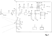
- FIG. 1 schematically shows the beam path in a coordinate measuring machine 1 in a preferred embodiment of the invention.
- the essential elements of the coordinate measuring machine 1 are arranged in or on a carrier 6, preferably in a common housing.
- a fine target detection unit 2 generates an infrared aiming beam 24, and a distance measuring device 4 generates a measuring light beam 44.
- the two beams exit through a common exit optics 63 and preferably extend coaxially along a measuring axis 60.
- a coarse target detection unit 3 with a second light source 33, and an overview camera 9 are also arranged on the support.
- a regulation and control system 7 acquires and processes the measured values of various sensors and controls axial bearing motors for aligning the carrier 6.
- a display device 8 displays information about measurements and the state of the device and can also display images of one of the existing image sensors, in particular the overview camera 9.
- the coordinate measuring machine 1 or the carrier 6 is aligned with a measuring aid 5, for example a retroreflector such as a triple mirror or a cube-corner prism.
- the two beams are reflected thereon and visible as the infrared target point or first target point 25 for the coordinate measuring machine 1 or as the second target point 35 for the distance measuring device 4.
- the second target point 35 is geometrically and viewed from the meter 1 from at least approximately or exactly at the same location in space as the first target point 25 visible.
- the two points 25, 35 are regarded as different from one another.
- the distance measuring device 4 is in the example shown an absolute distance measuring device, but may also be an interferometer, or a combination of both.
- a measuring light source 43 radiates the measuring light beam 44. This passes through a first beam splitter 451 for splitting the emitted light and a second beam splitter 455 for deflecting the returning light.
- the two beam splitters 451, 455 are part of a sensor unit 45.
- the deflected part of the emitted light is widened by means of a beam widening 452 and guided to two intensity sensors 453, 454.
- One of these intensity sensors 453 is used in a known manner to control the amplitude of the measuring light source 43, the other 454 as an additional fuse element for detecting an impermissibly high intensity.
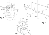
- the beam expansion 452 preferably has a cylinder prism or a series of juxtaposed and, for example, integrally molded cylinder prisms. A perspective view of the main elements of the sensor unit 45 is shown in FIG FIG. 2 shown.
- the return light deflected by the second beam splitter 455 is directed to a detector 456.
- the intensity detected there is used in a known manner to determine the absolute distance, for example according to the Fizeau principle.
- outgoing and returning measuring light 44 pass through an electrooptical modulator 46, a quarter wave plate 47, a beam widening 48, a deflecting mirror 49 and a beam splitter 41, which combines the measuring light beam 44 with the infrared aiming beam 24 of the fine target detection unit 2, respectively on the return path separates again.
- the fine target detection unit 2 has an infrared light source 23 which generates the target infrared beam 24. This is coupled via a second coupling 28, and passes through an optional further beam widening 29 and the beam splitter 41 on the measuring axis 60.
- the radiated by the infrared light source 23 infrared light is characterized as a target beam 24 in the common beam path of the distance measuring device 4 and the fine-target detection unit 2 coupled.
- the second coupling 28 the returning light is decoupled again in accordance with the infrared target point 25 and passes through a first coupling 26 and a first bandpass filter 20 to the first position detection sensor 21. There, the fine position 22 of the image of the infrared target point 25 on the first position detection sensor 21 generated.
- light is optionally coupled from a pointer light source 27 and passes as a beam in the common beam path of the distance measuring device 4 and the fine target detection unit 2.
- This light of the pointer light source 27 is in the visible range, so that the measuring axis 60 when hitting an object is also visible to an operator.
- visible Range are considered wavelengths of about 380-750 nm.
- the transition to the IR range is between 700 nm and 800 nm.
- the rough target detection unit 3 has a second position detection sensor 31.
- Light from the second light source 33 which may comprise a single or a plurality of individual light sources, is emitted at a relatively large emission angle.
- the radiation angle is slightly larger than the viewing angle range of the coarse target detection unit 3, which is more than 3 ° or more than 10 ° or more than 15 ° or up to about 30 ° (i.e., ⁇ 15 °).
- the measuring aid 5 for the coarse target detection unit 3 is also visible if it is not detected in the fine target detection unit 2.
- the reflection of the light of the second light source 33 is visible and measurable as a coarse position 32 on a second position detection sensor 31 of the coarse target detection unit 3. Based on this measurement, the carrier 6 is aligned with the measuring aid 5 until the fine target detection unit 2 detects its own infrared aiming beam 24. Subsequently, the fine position 22 is used to track the measuring aid 5 ("tracking").
- the second light source 33 must be arranged close to the entrance optics of the coarse target detection unit 3.
- the fine target detection unit 2 has a first bandpass filter 20 with a first passband
- the coarse targeting unit 3 has a second bandpass filter 30 with a second passband, wherein the two passbands do not overlap.
- the two wavelength ranges are 890-920 nm for the fine-target detection unit 2 and 835-865 nm for the coarse-target detection unit 3.
- the first band-pass filter 20 filters Measuring light of the distance measuring device 4 from (from the measuring light source 43), which passes through the beam splitter 41 to the fine-target detection unit 2 and could disturb them.
- the second light source 33 can, in addition to the light in the IR range, also emit light in the visible range and thereby also serve as illumination for the overview camera 9.
- the overview camera 9 can also have its own illumination 91 for emitting light at least in the visible range.
- FIG. 3 schematically shows the external structure of a coordinate measuring machine 1 with the already described elements exit optics 63, coarse target detection unit 3 with two second light sources 33 on two sides of the entrance optics of coarse target detection unit 30, and the overview camera 9 with its illumination 91, here also with two individual light sources on two sides of the entrance optics of the overview camera 9. Further shown are: the measuring axis 60, a tilting axis 62 about which the carrier 6 is tiltable with respect to an intermediate carrier 64, and a pivot axis 61 about which the intermediate carrier 64 is rotatable with respect to a base 65 is.
- FIG. 4 schematically shows an offset dZ between the infrared aiming beam 24 inside and outside the carrier 6 and the housing.
- the infrared aiming beam 24 preferably cuts both a vertical pivot axis 61 (or standing axis) and a horizontal tilt axis 62 (or tilt axis) of the carrier 6 for mechanical reasons.
- the standing axis 61 is perpendicular to the tilt axis 62, which in turn is perpendicular to a target axis and the measuring axis 60.
- the target axis (or mechanical Kollimationsachse) corresponds to the course of the infrared target beam 24 inside the carrier (up to the beam splitter 41).
- the target axis, the pivot axis 61 and the tilt axis 62 intersect at a point.
- the measuring axis 60 intersects here but only the pivot axis 61 but not the Tilting axis 62. In an embodiment of the invention, not shown, the measuring axis 60 intersects only the tilt axis 62 but not the pivot axis 61. In a further embodiment of the invention, not shown, the measuring axis 60 intersects neither the pivot axis 61 nor the tilt axis 62.
- the measuring axis 60 and the tilting axis 62 are spaced apart by a distance of at least a half or a whole millimeter, preferably between 1.4 mm and 2.5 mm.
- the displacement of the infrared target beam 24 of the fine target detection unit 2 is effected by the beam splitter 41 which is located as a plate in the beam path of the infrared aiming beam 24, and acts as a mirror for the measuring light beam 44.
Landscapes
- Physics & Mathematics (AREA)
- Engineering & Computer Science (AREA)
- Electromagnetism (AREA)
- Radar, Positioning & Navigation (AREA)
- Remote Sensing (AREA)
- General Physics & Mathematics (AREA)
- Computer Networks & Wireless Communication (AREA)
- Length Measuring Devices By Optical Means (AREA)
- Measurement Of Optical Distance (AREA)
Applications Claiming Priority (3)
| Application Number | Priority Date | Filing Date | Title |
|---|---|---|---|
| CH9722009 | 2009-06-23 | ||
| PCT/CH2010/000153 WO2010148525A1 (de) | 2009-06-23 | 2010-06-14 | Koordinatenmessgerät |
| EP10724241.4A EP2446299B1 (de) | 2009-06-23 | 2010-06-14 | Koordinatenmessgerät |
Related Parent Applications (2)
| Application Number | Title | Priority Date | Filing Date |
|---|---|---|---|
| EP10724241.4A Division-Into EP2446299B1 (de) | 2009-06-23 | 2010-06-14 | Koordinatenmessgerät |
| EP10724241.4A Division EP2446299B1 (de) | 2009-06-23 | 2010-06-14 | Koordinatenmessgerät |
Publications (2)
| Publication Number | Publication Date |
|---|---|
| EP3078983A1 EP3078983A1 (de) | 2016-10-12 |
| EP3078983B1 true EP3078983B1 (de) | 2018-08-08 |
Family
ID=41226381
Family Applications (2)
| Application Number | Title | Priority Date | Filing Date |
|---|---|---|---|
| EP15195689.3A Active EP3078983B1 (de) | 2009-06-23 | 2010-06-14 | Koordinatenmessgerät |
| EP10724241.4A Active EP2446299B1 (de) | 2009-06-23 | 2010-06-14 | Koordinatenmessgerät |
Family Applications After (1)
| Application Number | Title | Priority Date | Filing Date |
|---|---|---|---|
| EP10724241.4A Active EP2446299B1 (de) | 2009-06-23 | 2010-06-14 | Koordinatenmessgerät |
Country Status (6)
| Country | Link |
|---|---|
| US (2) | US8772719B2 (enExample) |
| EP (2) | EP3078983B1 (enExample) |
| JP (2) | JP2012530908A (enExample) |
| CN (1) | CN102803987B (enExample) |
| CA (1) | CA2766424C (enExample) |
| WO (1) | WO2010148525A1 (enExample) |
Families Citing this family (79)
| Publication number | Priority date | Publication date | Assignee | Title |
|---|---|---|---|---|
| DE102006031580A1 (de) | 2006-07-03 | 2008-01-17 | Faro Technologies, Inc., Lake Mary | Verfahren und Vorrichtung zum dreidimensionalen Erfassen eines Raumbereichs |
| US9482755B2 (en) | 2008-11-17 | 2016-11-01 | Faro Technologies, Inc. | Measurement system having air temperature compensation between a target and a laser tracker |
| DE102009015920B4 (de) | 2009-03-25 | 2014-11-20 | Faro Technologies, Inc. | Vorrichtung zum optischen Abtasten und Vermessen einer Umgebung |
| US9551575B2 (en) | 2009-03-25 | 2017-01-24 | Faro Technologies, Inc. | Laser scanner having a multi-color light source and real-time color receiver |
| US8659749B2 (en) | 2009-08-07 | 2014-02-25 | Faro Technologies, Inc. | Absolute distance meter with optical switch |
| DE102009057101A1 (de) | 2009-11-20 | 2011-05-26 | Faro Technologies, Inc., Lake Mary | Vorrichtung zum optischen Abtasten und Vermessen einer Umgebung |
| US9529083B2 (en) | 2009-11-20 | 2016-12-27 | Faro Technologies, Inc. | Three-dimensional scanner with enhanced spectroscopic energy detector |
| US9113023B2 (en) | 2009-11-20 | 2015-08-18 | Faro Technologies, Inc. | Three-dimensional scanner with spectroscopic energy detector |
| US8630314B2 (en) | 2010-01-11 | 2014-01-14 | Faro Technologies, Inc. | Method and apparatus for synchronizing measurements taken by multiple metrology devices |
| US8677643B2 (en) | 2010-01-20 | 2014-03-25 | Faro Technologies, Inc. | Coordinate measurement machines with removable accessories |
| DE112011100309B4 (de) | 2010-01-20 | 2015-06-11 | Faro Technologies, Inc. | Tragbares Gelenkarm-Koordinatenmessgerät mit abnehmbarem Zubehör |
| US9607239B2 (en) | 2010-01-20 | 2017-03-28 | Faro Technologies, Inc. | Articulated arm coordinate measurement machine having a 2D camera and method of obtaining 3D representations |
| US9163922B2 (en) | 2010-01-20 | 2015-10-20 | Faro Technologies, Inc. | Coordinate measurement machine with distance meter and camera to determine dimensions within camera images |
| US8898919B2 (en) | 2010-01-20 | 2014-12-02 | Faro Technologies, Inc. | Coordinate measurement machine with distance meter used to establish frame of reference |
| US8875409B2 (en) | 2010-01-20 | 2014-11-04 | Faro Technologies, Inc. | Coordinate measurement machines with removable accessories |
| US8284407B2 (en) | 2010-01-20 | 2012-10-09 | Faro Technologies, Inc. | Coordinate measuring machine having an illuminated probe end and method of operation |
| US9628775B2 (en) | 2010-01-20 | 2017-04-18 | Faro Technologies, Inc. | Articulated arm coordinate measurement machine having a 2D camera and method of obtaining 3D representations |
| US9879976B2 (en) | 2010-01-20 | 2018-01-30 | Faro Technologies, Inc. | Articulated arm coordinate measurement machine that uses a 2D camera to determine 3D coordinates of smoothly continuous edge features |
| US8615893B2 (en) | 2010-01-20 | 2013-12-31 | Faro Technologies, Inc. | Portable articulated arm coordinate measuring machine having integrated software controls |
| US8832954B2 (en) | 2010-01-20 | 2014-09-16 | Faro Technologies, Inc. | Coordinate measurement machines with removable accessories |
| DE112011100302T5 (de) | 2010-01-20 | 2012-10-25 | Faro Technologies, Inc. | Tragbares Gelenkarm-Koordinatenmessgerät mit mehreren Kommunikationskanälen |
| US8619265B2 (en) | 2011-03-14 | 2013-12-31 | Faro Technologies, Inc. | Automatic measurement of dimensional data with a laser tracker |
| US9400170B2 (en) | 2010-04-21 | 2016-07-26 | Faro Technologies, Inc. | Automatic measurement of dimensional data within an acceptance region by a laser tracker |
| US9377885B2 (en) | 2010-04-21 | 2016-06-28 | Faro Technologies, Inc. | Method and apparatus for locking onto a retroreflector with a laser tracker |
| US9772394B2 (en) | 2010-04-21 | 2017-09-26 | Faro Technologies, Inc. | Method and apparatus for following an operator and locking onto a retroreflector with a laser tracker |
| DE102010020925B4 (de) | 2010-05-10 | 2014-02-27 | Faro Technologies, Inc. | Verfahren zum optischen Abtasten und Vermessen einer Umgebung |
| DE112011102995B4 (de) | 2010-09-08 | 2016-05-19 | Faro Technologies Inc. | Laserscanner oder Lasernachführungsgerät mit einem Projektor |
| US9168654B2 (en) | 2010-11-16 | 2015-10-27 | Faro Technologies, Inc. | Coordinate measuring machines with dual layer arm |
| US8902408B2 (en) | 2011-02-14 | 2014-12-02 | Faro Technologies Inc. | Laser tracker used with six degree-of-freedom probe having separable spherical retroreflector |
| GB2518998A (en) | 2011-03-03 | 2015-04-08 | Faro Tech Inc | Target apparatus and method |
| US9164173B2 (en) | 2011-04-15 | 2015-10-20 | Faro Technologies, Inc. | Laser tracker that uses a fiber-optic coupler and an achromatic launch to align and collimate two wavelengths of light |
| US9686532B2 (en) | 2011-04-15 | 2017-06-20 | Faro Technologies, Inc. | System and method of acquiring three-dimensional coordinates using multiple coordinate measurement devices |
| USD688577S1 (en) | 2012-02-21 | 2013-08-27 | Faro Technologies, Inc. | Laser tracker |
| DE112012001708B4 (de) | 2011-04-15 | 2018-05-09 | Faro Technologies, Inc. | Koordinatenmessgerät |
| US9482529B2 (en) | 2011-04-15 | 2016-11-01 | Faro Technologies, Inc. | Three-dimensional coordinate scanner and method of operation |
| US9222771B2 (en) | 2011-10-17 | 2015-12-29 | Kla-Tencor Corp. | Acquisition of information for a construction site |
| DE102011119480B4 (de) | 2011-11-28 | 2013-11-14 | Eads Deutschland Gmbh | Verfahren und Vorrichtung zur Verfolgung eines bewegten Zielobjekts |
| EP2602641B1 (de) | 2011-12-06 | 2014-02-26 | Leica Geosystems AG | Lasertracker mit positionssensitiven Detektoren zur Suche eines Ziels |
| EP2618175A1 (de) | 2012-01-17 | 2013-07-24 | Leica Geosystems AG | Lasertracker mit Funktionalität zur graphischen Zielbereitstellung |
| DE102012100609A1 (de) | 2012-01-25 | 2013-07-25 | Faro Technologies, Inc. | Vorrichtung zum optischen Abtasten und Vermessen einer Umgebung |
| DE112013000727T5 (de) | 2012-01-27 | 2014-11-06 | Faro Technologies, Inc. | Prüfverfahren mit Strichcode-Kennzeichnung |
| JP6129475B2 (ja) * | 2012-02-29 | 2017-05-17 | 三菱重工業株式会社 | 監視装置及び監視方法 |
| EP2634594A1 (de) * | 2012-03-01 | 2013-09-04 | Leica Geosystems AG | Verfahren zum Bestimmen einer Entfernungsänderung mittels Interferometrie |
| US8997362B2 (en) | 2012-07-17 | 2015-04-07 | Faro Technologies, Inc. | Portable articulated arm coordinate measuring machine with optical communications bus |
| EP2687866A1 (de) | 2012-07-19 | 2014-01-22 | Leica Geosystems AG | Lasertracker mit Kalibriereinheit zur Selbstkalibrierung |
| EP2706376A1 (de) | 2012-09-07 | 2014-03-12 | Leica Geosystems AG | Lasertracker mit hybridem Abbildungsverfahren zur Erweiterung der Messreichweite |
| DE102012109481A1 (de) | 2012-10-05 | 2014-04-10 | Faro Technologies, Inc. | Vorrichtung zum optischen Abtasten und Vermessen einer Umgebung |
| US10067231B2 (en) | 2012-10-05 | 2018-09-04 | Faro Technologies, Inc. | Registration calculation of three-dimensional scanner data performed between scans based on measurements by two-dimensional scanner |
| US9513107B2 (en) | 2012-10-05 | 2016-12-06 | Faro Technologies, Inc. | Registration calculation between three-dimensional (3D) scans based on two-dimensional (2D) scan data from a 3D scanner |
| EP2728375A1 (de) | 2012-10-31 | 2014-05-07 | Leica Geosystems AG | Verfahren und Vorrichtung zur Bestimmung einer Orientierung eines Objekts |
| JP6129545B2 (ja) * | 2012-12-18 | 2017-05-17 | Ntn株式会社 | 空間座標測定装置および空間座標測定方法 |
| TWI476427B (zh) * | 2013-01-14 | 2015-03-11 | Sintai Optical Shenzhen Co Ltd | 測距儀 |
| US9041914B2 (en) | 2013-03-15 | 2015-05-26 | Faro Technologies, Inc. | Three-dimensional coordinate scanner and method of operation |
| EP2789972B1 (de) | 2013-04-12 | 2017-08-16 | Hexagon Technology Center GmbH | Vermessungsgerät mit verformbarem optischem Element |
| EP2801841B1 (de) | 2013-05-10 | 2018-07-04 | Leica Geosystems AG | Lasertracker mit einer Zielerfassungseinheit für eine Zielverfolgung und eine Orientierungserkennung |
| US9476695B2 (en) * | 2013-07-03 | 2016-10-25 | Faro Technologies, Inc. | Laser tracker that cooperates with a remote camera bar and coordinate measurement device |
| EP2827099A1 (de) | 2013-07-16 | 2015-01-21 | Leica Geosystems AG | Lasertracker mit Zielsuchfunktionalität |
| JP6032195B2 (ja) * | 2013-12-26 | 2016-11-24 | トヨタ自動車株式会社 | センサ異常検出装置 |
| CN103837138B (zh) * | 2014-03-25 | 2014-12-17 | 许凯华 | 精密摄影测量机器人 |
| US9395174B2 (en) | 2014-06-27 | 2016-07-19 | Faro Technologies, Inc. | Determining retroreflector orientation by optimizing spatial fit |
| CN105372665B (zh) * | 2014-08-27 | 2017-09-12 | 北京顶亮科技有限公司 | 一种红外毫米波测距设备及方法 |
| USD754130S1 (en) * | 2015-03-19 | 2016-04-19 | Faro Technologies, Inc. | Optical scanner |
| FR3035720B1 (fr) * | 2015-04-30 | 2017-06-23 | Thales Sa | Systeme optique et procede de pointage laser a travers l'atmosphere |
| DE102015122844A1 (de) | 2015-12-27 | 2017-06-29 | Faro Technologies, Inc. | 3D-Messvorrichtung mit Batteriepack |
| CN106443698A (zh) * | 2016-10-27 | 2017-02-22 | 青岛科技大学 | 一种固体激光测速仪双光束干涉交点位置的调节装置 |
| EP3339803B1 (de) | 2016-12-22 | 2021-05-12 | Leica Geosystems AG | Koordinatenmessgerät mit automatischer zielobjekterkennung |
| EP3502617B1 (de) * | 2017-12-21 | 2021-10-20 | Leica Geosystems AG | Vermessungsgerät mit messstrahlhomogenisierung |
| WO2019176101A1 (ja) * | 2018-03-16 | 2019-09-19 | 日本電気株式会社 | 光監視装置及び方法 |
| EP3736530B1 (de) | 2019-05-06 | 2023-03-22 | Hexagon Technology Center GmbH | Automatisches auffinden von zielmarken |
| US11733043B2 (en) | 2019-05-06 | 2023-08-22 | Hexagon Technology Center Gmbh | Automatic locating of target marks |
| EP3783305B1 (en) | 2019-08-21 | 2022-03-23 | Leica Geosystems AG | Drive system in a geodetic measurement instrument |
| EP3812701B1 (en) | 2019-10-23 | 2022-08-24 | Hexagon Technology Center GmbH | Online leveling calibration of a geodetic instrument |
| DE102020007996A1 (de) | 2020-12-17 | 2022-06-23 | Atlas Elektronik Gmbh | Fürhrungssystem zur Ausrichtung einer Rohrwaffe |
| CN112556579A (zh) * | 2020-12-25 | 2021-03-26 | 深圳市中图仪器股份有限公司 | 一种六自由度空间坐标位置和姿态测量装置 |
| EP4198449A1 (en) | 2021-12-14 | 2023-06-21 | Hexagon Technology Center GmbH | Metrology system |
| CN114353834B (zh) * | 2022-01-10 | 2025-08-12 | 深圳市中图仪器股份有限公司 | 姿态探头的标定方法 |
| EP4343272B1 (en) | 2022-09-20 | 2024-11-06 | Hexagon Technology Center GmbH | Sensor with curved reflector |
| EP4354084A1 (en) | 2022-10-10 | 2024-04-17 | Hexagon Technology Center GmbH | In-the-field leveling calibration of a surveying instrument |
| JP2025006183A (ja) * | 2023-06-29 | 2025-01-17 | 株式会社トプコン | 測量装置 |
Family Cites Families (12)
| Publication number | Priority date | Publication date | Assignee | Title |
|---|---|---|---|---|
| JP3621123B2 (ja) * | 1993-12-28 | 2005-02-16 | 株式会社トプコン | 測量機 |
| DE19840049C5 (de) * | 1998-09-02 | 2007-11-08 | Leica Geosystems Ag | Vorrichtung zur optischen Distanzmessung |
| JP4088906B2 (ja) | 1998-12-16 | 2008-05-21 | 株式会社トプコン | 測量機の受光装置 |
| US7800758B1 (en) * | 1999-07-23 | 2010-09-21 | Faro Laser Trackers, Llc | Laser-based coordinate measuring device and laser-based method for measuring coordinates |
| ATE219575T1 (de) | 1999-08-31 | 2002-07-15 | Leica Geosystems Ag | Tachymeter-fernrohr |
| JP3626141B2 (ja) * | 2001-08-10 | 2005-03-02 | 株式会社ソキア | 撮像装置を備えた自動視準測量機 |
| EP1329690A1 (de) | 2002-01-22 | 2003-07-23 | Leica Geosystems AG | Verfahren und Vorrichtung zum automatischen Auffinden von Zielmarken |
| JP4127503B2 (ja) * | 2002-11-22 | 2008-07-30 | 株式会社トプコン | 反射体自動追尾装置 |
| EP1971878B1 (de) | 2006-01-13 | 2013-07-31 | Leica Geosystems AG | Tracking-verfahren und messsystem mit laser-tracker |
| CN102680983B (zh) * | 2006-01-13 | 2015-07-29 | 莱卡地球系统公开股份有限公司 | 坐标测量设备 |
| JP5150234B2 (ja) | 2007-12-14 | 2013-02-20 | 株式会社トプコン | 測量装置 |
| EP2381269A1 (de) * | 2010-04-13 | 2011-10-26 | Leica Geosystems AG | Koordinatenmessgerät mit automatischer Zielerfassung |
-
2010
- 2010-06-14 JP JP2012516461A patent/JP2012530908A/ja active Pending
- 2010-06-14 EP EP15195689.3A patent/EP3078983B1/de active Active
- 2010-06-14 CA CA2766424A patent/CA2766424C/en not_active Expired - Fee Related
- 2010-06-14 US US13/377,739 patent/US8772719B2/en active Active
- 2010-06-14 WO PCT/CH2010/000153 patent/WO2010148525A1/de not_active Ceased
- 2010-06-14 EP EP10724241.4A patent/EP2446299B1/de active Active
- 2010-06-14 CN CN201080027906.2A patent/CN102803987B/zh active Active
-
2014
- 2014-06-04 US US14/296,293 patent/US9366531B2/en active Active
-
2016
- 2016-02-05 JP JP2016020704A patent/JP6242411B2/ja not_active Expired - Fee Related
Non-Patent Citations (1)
| Title |
|---|
| None * |
Also Published As
| Publication number | Publication date |
|---|---|
| US8772719B2 (en) | 2014-07-08 |
| CA2766424C (en) | 2017-08-29 |
| CN102803987A (zh) | 2012-11-28 |
| JP2012530908A (ja) | 2012-12-06 |
| CA2766424A1 (en) | 2010-12-29 |
| US20120113406A1 (en) | 2012-05-10 |
| EP2446299A1 (de) | 2012-05-02 |
| JP6242411B2 (ja) | 2017-12-06 |
| US9366531B2 (en) | 2016-06-14 |
| JP2016106226A (ja) | 2016-06-16 |
| EP2446299B1 (de) | 2016-08-10 |
| US20140285792A1 (en) | 2014-09-25 |
| CN102803987B (zh) | 2015-09-16 |
| EP3078983A1 (de) | 2016-10-12 |
| WO2010148525A1 (de) | 2010-12-29 |
Similar Documents
| Publication | Publication Date | Title |
|---|---|---|
| EP3078983B1 (de) | Koordinatenmessgerät | |
| EP2558880B1 (de) | Koordinatenmessgerät mit automatischer zielerfassung | |
| EP2446300B1 (de) | Tracking-verfahren und messsystem mit lasertracker | |
| EP0987564B1 (de) | Vorrichtung zur optischen Distanzmessung | |
| EP1971821B1 (de) | Koordinatenmessgerät | |
| EP2746806B1 (de) | Selbstkalibrierender Lasertracker und Selbstkalibrierungsverfahren | |
| EP2810020B1 (de) | Vermessungsgerät mit scanfunktionalität und einzelpunktmessmodus | |
| DE102013227101B3 (de) | Optisches System zur Nachverfolgung eines Ziels | |
| EP2875383B1 (de) | Lasertracker mit kalibriereinheit zur selbstkalibrierung | |
| EP2773980B1 (de) | Laserdiode als interferometer-laserstrahlquelle in einem lasertracker | |
| EP3845859B1 (de) | Koordinatenmessgerät mit automatischer zielobjekterkennung | |
| EP2801841A1 (de) | Lasertracker mit einer Zielerfassungseinheit für eine Zielverfolgung und eine Orientierungserkennung | |
| EP2936203A1 (de) | Selbstkalibrierender lasertracker und selbstkalibrierungsverfahren | |
| DE10250583A1 (de) | Elektronischer Entfernungsmesser | |
| EP2238497A2 (de) | Optisches system zur projektion eines ir- oder uv-testsignals mit optischer ausrichtung der projektionsachse im sichtbaren spektralbereich | |
| EP3502617B1 (de) | Vermessungsgerät mit messstrahlhomogenisierung | |
| DE102015016274B4 (de) | Optisches System und Verfahren zum Justieren eines Signalstrahls | |
| EP2690398B1 (de) | Vorrichtung zum Ermitteln der Lage von mechanischen Elementen | |
| DE102006037967B3 (de) | Michelson-Interferometer | |
| DD287776A5 (de) | Anordnung zur projektion einer lichtmarke, vorzugsweise mit einem theodoliten |
Legal Events
| Date | Code | Title | Description |
|---|---|---|---|
| PUAI | Public reference made under article 153(3) epc to a published international application that has entered the european phase |
Free format text: ORIGINAL CODE: 0009012 |
|
| AC | Divisional application: reference to earlier application |
Ref document number: 2446299 Country of ref document: EP Kind code of ref document: P |
|
| AK | Designated contracting states |
Kind code of ref document: A1 Designated state(s): AL AT BE BG CH CY CZ DE DK EE ES FI FR GB GR HR HU IE IS IT LI LT LU LV MC MK MT NL NO PL PT RO SE SI SK SM TR |
|
| STAA | Information on the status of an ep patent application or granted ep patent |
Free format text: STATUS: REQUEST FOR EXAMINATION WAS MADE |
|
| 17P | Request for examination filed |
Effective date: 20170410 |
|
| RBV | Designated contracting states (corrected) |
Designated state(s): AL AT BE BG CH CY CZ DE DK EE ES FI FR GB GR HR HU IE IS IT LI LT LU LV MC MK MT NL NO PL PT RO SE SI SK SM TR |
|
| GRAP | Despatch of communication of intention to grant a patent |
Free format text: ORIGINAL CODE: EPIDOSNIGR1 |
|
| STAA | Information on the status of an ep patent application or granted ep patent |
Free format text: STATUS: GRANT OF PATENT IS INTENDED |
|
| INTG | Intention to grant announced |
Effective date: 20180212 |
|
| GRAS | Grant fee paid |
Free format text: ORIGINAL CODE: EPIDOSNIGR3 |
|
| GRAA | (expected) grant |
Free format text: ORIGINAL CODE: 0009210 |
|
| STAA | Information on the status of an ep patent application or granted ep patent |
Free format text: STATUS: THE PATENT HAS BEEN GRANTED |
|
| AC | Divisional application: reference to earlier application |
Ref document number: 2446299 Country of ref document: EP Kind code of ref document: P |
|
| AK | Designated contracting states |
Kind code of ref document: B1 Designated state(s): AL AT BE BG CH CY CZ DE DK EE ES FI FR GB GR HR HU IE IS IT LI LT LU LV MC MK MT NL NO PL PT RO SE SI SK SM TR |
|
| REG | Reference to a national code |
Ref country code: GB Ref legal event code: FG4D Free format text: NOT ENGLISH |
|
| REG | Reference to a national code |
Ref country code: CH Ref legal event code: EP Ref country code: AT Ref legal event code: REF Ref document number: 1027647 Country of ref document: AT Kind code of ref document: T Effective date: 20180815 |
|
| REG | Reference to a national code |
Ref country code: IE Ref legal event code: FG4D Free format text: LANGUAGE OF EP DOCUMENT: GERMAN |
|
| REG | Reference to a national code |
Ref country code: DE Ref legal event code: R096 Ref document number: 502010015256 Country of ref document: DE |
|
| REG | Reference to a national code |
Ref country code: CH Ref legal event code: NV Representative=s name: KAMINSKI HARMANN PATENTANWAELTE AG, LI |
|
| REG | Reference to a national code |
Ref country code: NL Ref legal event code: FP |
|
| REG | Reference to a national code |
Ref country code: SE Ref legal event code: TRGR |
|
| REG | Reference to a national code |
Ref country code: LT Ref legal event code: MG4D |
|
| PG25 | Lapsed in a contracting state [announced via postgrant information from national office to epo] |
Ref country code: FI Free format text: LAPSE BECAUSE OF FAILURE TO SUBMIT A TRANSLATION OF THE DESCRIPTION OR TO PAY THE FEE WITHIN THE PRESCRIBED TIME-LIMIT Effective date: 20180808 Ref country code: PL Free format text: LAPSE BECAUSE OF FAILURE TO SUBMIT A TRANSLATION OF THE DESCRIPTION OR TO PAY THE FEE WITHIN THE PRESCRIBED TIME-LIMIT Effective date: 20180808 Ref country code: GR Free format text: LAPSE BECAUSE OF FAILURE TO SUBMIT A TRANSLATION OF THE DESCRIPTION OR TO PAY THE FEE WITHIN THE PRESCRIBED TIME-LIMIT Effective date: 20181109 Ref country code: NO Free format text: LAPSE BECAUSE OF FAILURE TO SUBMIT A TRANSLATION OF THE DESCRIPTION OR TO PAY THE FEE WITHIN THE PRESCRIBED TIME-LIMIT Effective date: 20181108 Ref country code: BG Free format text: LAPSE BECAUSE OF FAILURE TO SUBMIT A TRANSLATION OF THE DESCRIPTION OR TO PAY THE FEE WITHIN THE PRESCRIBED TIME-LIMIT Effective date: 20181108 Ref country code: LT Free format text: LAPSE BECAUSE OF FAILURE TO SUBMIT A TRANSLATION OF THE DESCRIPTION OR TO PAY THE FEE WITHIN THE PRESCRIBED TIME-LIMIT Effective date: 20180808 Ref country code: IS Free format text: LAPSE BECAUSE OF FAILURE TO SUBMIT A TRANSLATION OF THE DESCRIPTION OR TO PAY THE FEE WITHIN THE PRESCRIBED TIME-LIMIT Effective date: 20181208 |
|
| PG25 | Lapsed in a contracting state [announced via postgrant information from national office to epo] |
Ref country code: HR Free format text: LAPSE BECAUSE OF FAILURE TO SUBMIT A TRANSLATION OF THE DESCRIPTION OR TO PAY THE FEE WITHIN THE PRESCRIBED TIME-LIMIT Effective date: 20180808 Ref country code: AL Free format text: LAPSE BECAUSE OF FAILURE TO SUBMIT A TRANSLATION OF THE DESCRIPTION OR TO PAY THE FEE WITHIN THE PRESCRIBED TIME-LIMIT Effective date: 20180808 Ref country code: LV Free format text: LAPSE BECAUSE OF FAILURE TO SUBMIT A TRANSLATION OF THE DESCRIPTION OR TO PAY THE FEE WITHIN THE PRESCRIBED TIME-LIMIT Effective date: 20180808 |
|
| PG25 | Lapsed in a contracting state [announced via postgrant information from national office to epo] |
Ref country code: ES Free format text: LAPSE BECAUSE OF FAILURE TO SUBMIT A TRANSLATION OF THE DESCRIPTION OR TO PAY THE FEE WITHIN THE PRESCRIBED TIME-LIMIT Effective date: 20180808 Ref country code: CZ Free format text: LAPSE BECAUSE OF FAILURE TO SUBMIT A TRANSLATION OF THE DESCRIPTION OR TO PAY THE FEE WITHIN THE PRESCRIBED TIME-LIMIT Effective date: 20180808 Ref country code: EE Free format text: LAPSE BECAUSE OF FAILURE TO SUBMIT A TRANSLATION OF THE DESCRIPTION OR TO PAY THE FEE WITHIN THE PRESCRIBED TIME-LIMIT Effective date: 20180808 Ref country code: RO Free format text: LAPSE BECAUSE OF FAILURE TO SUBMIT A TRANSLATION OF THE DESCRIPTION OR TO PAY THE FEE WITHIN THE PRESCRIBED TIME-LIMIT Effective date: 20180808 Ref country code: IT Free format text: LAPSE BECAUSE OF FAILURE TO SUBMIT A TRANSLATION OF THE DESCRIPTION OR TO PAY THE FEE WITHIN THE PRESCRIBED TIME-LIMIT Effective date: 20180808 |
|
| REG | Reference to a national code |
Ref country code: DE Ref legal event code: R097 Ref document number: 502010015256 Country of ref document: DE |
|
| PG25 | Lapsed in a contracting state [announced via postgrant information from national office to epo] |
Ref country code: DK Free format text: LAPSE BECAUSE OF FAILURE TO SUBMIT A TRANSLATION OF THE DESCRIPTION OR TO PAY THE FEE WITHIN THE PRESCRIBED TIME-LIMIT Effective date: 20180808 Ref country code: SK Free format text: LAPSE BECAUSE OF FAILURE TO SUBMIT A TRANSLATION OF THE DESCRIPTION OR TO PAY THE FEE WITHIN THE PRESCRIBED TIME-LIMIT Effective date: 20180808 Ref country code: SM Free format text: LAPSE BECAUSE OF FAILURE TO SUBMIT A TRANSLATION OF THE DESCRIPTION OR TO PAY THE FEE WITHIN THE PRESCRIBED TIME-LIMIT Effective date: 20180808 |
|
| PLBE | No opposition filed within time limit |
Free format text: ORIGINAL CODE: 0009261 |
|
| STAA | Information on the status of an ep patent application or granted ep patent |
Free format text: STATUS: NO OPPOSITION FILED WITHIN TIME LIMIT |
|
| 26N | No opposition filed |
Effective date: 20190509 |
|
| PG25 | Lapsed in a contracting state [announced via postgrant information from national office to epo] |
Ref country code: SI Free format text: LAPSE BECAUSE OF FAILURE TO SUBMIT A TRANSLATION OF THE DESCRIPTION OR TO PAY THE FEE WITHIN THE PRESCRIBED TIME-LIMIT Effective date: 20180808 |
|
| PG25 | Lapsed in a contracting state [announced via postgrant information from national office to epo] |
Ref country code: MC Free format text: LAPSE BECAUSE OF FAILURE TO SUBMIT A TRANSLATION OF THE DESCRIPTION OR TO PAY THE FEE WITHIN THE PRESCRIBED TIME-LIMIT Effective date: 20180808 |
|
| REG | Reference to a national code |
Ref country code: BE Ref legal event code: MM Effective date: 20190630 |
|
| PG25 | Lapsed in a contracting state [announced via postgrant information from national office to epo] |
Ref country code: TR Free format text: LAPSE BECAUSE OF FAILURE TO SUBMIT A TRANSLATION OF THE DESCRIPTION OR TO PAY THE FEE WITHIN THE PRESCRIBED TIME-LIMIT Effective date: 20180808 |
|
| PG25 | Lapsed in a contracting state [announced via postgrant information from national office to epo] |
Ref country code: IE Free format text: LAPSE BECAUSE OF NON-PAYMENT OF DUE FEES Effective date: 20190614 |
|
| PG25 | Lapsed in a contracting state [announced via postgrant information from national office to epo] |
Ref country code: BE Free format text: LAPSE BECAUSE OF NON-PAYMENT OF DUE FEES Effective date: 20190630 Ref country code: LU Free format text: LAPSE BECAUSE OF NON-PAYMENT OF DUE FEES Effective date: 20190614 |
|
| PG25 | Lapsed in a contracting state [announced via postgrant information from national office to epo] |
Ref country code: PT Free format text: LAPSE BECAUSE OF FAILURE TO SUBMIT A TRANSLATION OF THE DESCRIPTION OR TO PAY THE FEE WITHIN THE PRESCRIBED TIME-LIMIT Effective date: 20181208 |
|
| REG | Reference to a national code |
Ref country code: AT Ref legal event code: MM01 Ref document number: 1027647 Country of ref document: AT Kind code of ref document: T Effective date: 20190614 |
|
| PG25 | Lapsed in a contracting state [announced via postgrant information from national office to epo] |
Ref country code: AT Free format text: LAPSE BECAUSE OF NON-PAYMENT OF DUE FEES Effective date: 20190614 |
|
| PG25 | Lapsed in a contracting state [announced via postgrant information from national office to epo] |
Ref country code: CY Free format text: LAPSE BECAUSE OF FAILURE TO SUBMIT A TRANSLATION OF THE DESCRIPTION OR TO PAY THE FEE WITHIN THE PRESCRIBED TIME-LIMIT Effective date: 20180808 |
|
| PG25 | Lapsed in a contracting state [announced via postgrant information from national office to epo] |
Ref country code: HU Free format text: LAPSE BECAUSE OF FAILURE TO SUBMIT A TRANSLATION OF THE DESCRIPTION OR TO PAY THE FEE WITHIN THE PRESCRIBED TIME-LIMIT; INVALID AB INITIO Effective date: 20100614 Ref country code: MT Free format text: LAPSE BECAUSE OF FAILURE TO SUBMIT A TRANSLATION OF THE DESCRIPTION OR TO PAY THE FEE WITHIN THE PRESCRIBED TIME-LIMIT Effective date: 20180808 |
|
| PG25 | Lapsed in a contracting state [announced via postgrant information from national office to epo] |
Ref country code: MK Free format text: LAPSE BECAUSE OF FAILURE TO SUBMIT A TRANSLATION OF THE DESCRIPTION OR TO PAY THE FEE WITHIN THE PRESCRIBED TIME-LIMIT Effective date: 20180808 |
|
| PGFP | Annual fee paid to national office [announced via postgrant information from national office to epo] |
Ref country code: DE Payment date: 20250618 Year of fee payment: 16 |
|
| PGFP | Annual fee paid to national office [announced via postgrant information from national office to epo] |
Ref country code: GB Payment date: 20250618 Year of fee payment: 16 |
|
| PGFP | Annual fee paid to national office [announced via postgrant information from national office to epo] |
Ref country code: NL Payment date: 20250618 Year of fee payment: 16 |
|
| PGFP | Annual fee paid to national office [announced via postgrant information from national office to epo] |
Ref country code: FR Payment date: 20250625 Year of fee payment: 16 |
|
| PGFP | Annual fee paid to national office [announced via postgrant information from national office to epo] |
Ref country code: SE Payment date: 20250618 Year of fee payment: 16 |
|
| PGFP | Annual fee paid to national office [announced via postgrant information from national office to epo] |
Ref country code: CH Payment date: 20250701 Year of fee payment: 16 |