EP3078971A1 - Urine sample analyzer and urine sample dispensing method - Google Patents
Urine sample analyzer and urine sample dispensing method Download PDFInfo
- Publication number
- EP3078971A1 EP3078971A1 EP16161364.1A EP16161364A EP3078971A1 EP 3078971 A1 EP3078971 A1 EP 3078971A1 EP 16161364 A EP16161364 A EP 16161364A EP 3078971 A1 EP3078971 A1 EP 3078971A1
- Authority
- EP
- European Patent Office
- Prior art keywords
- nozzle
- sample
- urine sample
- holding chamber
- wash tank
- Prior art date
- Legal status (The legal status is an assumption and is not a legal conclusion. Google has not performed a legal analysis and makes no representation as to the accuracy of the status listed.)
- Granted
Links
Images





Classifications
-
- G—PHYSICS
- G01—MEASURING; TESTING
- G01N—INVESTIGATING OR ANALYSING MATERIALS BY DETERMINING THEIR CHEMICAL OR PHYSICAL PROPERTIES
- G01N33/00—Investigating or analysing materials by specific methods not covered by groups G01N1/00 - G01N31/00
- G01N33/48—Biological material, e.g. blood, urine; Haemocytometers
-
- G—PHYSICS
- G01—MEASURING; TESTING
- G01N—INVESTIGATING OR ANALYSING MATERIALS BY DETERMINING THEIR CHEMICAL OR PHYSICAL PROPERTIES
- G01N33/00—Investigating or analysing materials by specific methods not covered by groups G01N1/00 - G01N31/00
- G01N33/48—Biological material, e.g. blood, urine; Haemocytometers
- G01N33/483—Physical analysis of biological material
- G01N33/487—Physical analysis of biological material of liquid biological material
- G01N33/493—Physical analysis of biological material of liquid biological material urine
-
- B—PERFORMING OPERATIONS; TRANSPORTING
- B01—PHYSICAL OR CHEMICAL PROCESSES OR APPARATUS IN GENERAL
- B01L—CHEMICAL OR PHYSICAL LABORATORY APPARATUS FOR GENERAL USE
- B01L3/00—Containers or dishes for laboratory use, e.g. laboratory glassware; Droppers
- B01L3/50—Containers for the purpose of retaining a material to be analysed, e.g. test tubes
- B01L3/508—Rigid containers without fluid transport within
-
- B—PERFORMING OPERATIONS; TRANSPORTING
- B01—PHYSICAL OR CHEMICAL PROCESSES OR APPARATUS IN GENERAL
- B01L—CHEMICAL OR PHYSICAL LABORATORY APPARATUS FOR GENERAL USE
- B01L3/00—Containers or dishes for laboratory use, e.g. laboratory glassware; Droppers
- B01L3/52—Containers specially adapted for storing or dispensing a reagent
-
- G—PHYSICS
- G01—MEASURING; TESTING
- G01N—INVESTIGATING OR ANALYSING MATERIALS BY DETERMINING THEIR CHEMICAL OR PHYSICAL PROPERTIES
- G01N1/00—Sampling; Preparing specimens for investigation
- G01N1/02—Devices for withdrawing samples
- G01N1/10—Devices for withdrawing samples in the liquid or fluent state
- G01N1/14—Suction devices, e.g. pumps; Ejector devices
-
- G—PHYSICS
- G01—MEASURING; TESTING
- G01N—INVESTIGATING OR ANALYSING MATERIALS BY DETERMINING THEIR CHEMICAL OR PHYSICAL PROPERTIES
- G01N15/00—Investigating characteristics of particles; Investigating permeability, pore-volume or surface-area of porous materials
- G01N15/10—Investigating individual particles
- G01N15/14—Optical investigation techniques, e.g. flow cytometry
- G01N15/1456—Optical investigation techniques, e.g. flow cytometry without spatial resolution of the texture or inner structure of the particle, e.g. processing of pulse signals
- G01N15/1459—Optical investigation techniques, e.g. flow cytometry without spatial resolution of the texture or inner structure of the particle, e.g. processing of pulse signals the analysis being performed on a sample stream
-
- G—PHYSICS
- G01—MEASURING; TESTING
- G01N—INVESTIGATING OR ANALYSING MATERIALS BY DETERMINING THEIR CHEMICAL OR PHYSICAL PROPERTIES
- G01N35/00—Automatic analysis not limited to methods or materials provided for in any single one of groups G01N1/00 - G01N33/00; Handling materials therefor
- G01N35/00584—Control arrangements for automatic analysers
-
- G—PHYSICS
- G01—MEASURING; TESTING
- G01N—INVESTIGATING OR ANALYSING MATERIALS BY DETERMINING THEIR CHEMICAL OR PHYSICAL PROPERTIES
- G01N35/00—Automatic analysis not limited to methods or materials provided for in any single one of groups G01N1/00 - G01N33/00; Handling materials therefor
- G01N35/10—Devices for transferring samples or any liquids to, in, or from, the analysis apparatus, e.g. suction devices, injection devices
- G01N35/1004—Cleaning sample transfer devices
-
- G—PHYSICS
- G01—MEASURING; TESTING
- G01N—INVESTIGATING OR ANALYSING MATERIALS BY DETERMINING THEIR CHEMICAL OR PHYSICAL PROPERTIES
- G01N35/00—Automatic analysis not limited to methods or materials provided for in any single one of groups G01N1/00 - G01N33/00; Handling materials therefor
- G01N35/10—Devices for transferring samples or any liquids to, in, or from, the analysis apparatus, e.g. suction devices, injection devices
- G01N35/1095—Devices for transferring samples or any liquids to, in, or from, the analysis apparatus, e.g. suction devices, injection devices for supplying the samples to flow-through analysers
-
- B—PERFORMING OPERATIONS; TRANSPORTING
- B01—PHYSICAL OR CHEMICAL PROCESSES OR APPARATUS IN GENERAL
- B01L—CHEMICAL OR PHYSICAL LABORATORY APPARATUS FOR GENERAL USE
- B01L2200/00—Solutions for specific problems relating to chemical or physical laboratory apparatus
- B01L2200/06—Fluid handling related problems
-
- B—PERFORMING OPERATIONS; TRANSPORTING
- B01—PHYSICAL OR CHEMICAL PROCESSES OR APPARATUS IN GENERAL
- B01L—CHEMICAL OR PHYSICAL LABORATORY APPARATUS FOR GENERAL USE
- B01L2300/00—Additional constructional details
- B01L2300/06—Auxiliary integrated devices, integrated components
- B01L2300/0627—Sensor or part of a sensor is integrated
- B01L2300/0636—Integrated biosensor, microarrays
-
- B—PERFORMING OPERATIONS; TRANSPORTING
- B01—PHYSICAL OR CHEMICAL PROCESSES OR APPARATUS IN GENERAL
- B01L—CHEMICAL OR PHYSICAL LABORATORY APPARATUS FOR GENERAL USE
- B01L2400/00—Moving or stopping fluids
- B01L2400/04—Moving fluids with specific forces or mechanical means
- B01L2400/0475—Moving fluids with specific forces or mechanical means specific mechanical means and fluid pressure
- B01L2400/0487—Moving fluids with specific forces or mechanical means specific mechanical means and fluid pressure fluid pressure, pneumatics
- B01L2400/049—Moving fluids with specific forces or mechanical means specific mechanical means and fluid pressure fluid pressure, pneumatics vacuum
-
- G—PHYSICS
- G01—MEASURING; TESTING
- G01N—INVESTIGATING OR ANALYSING MATERIALS BY DETERMINING THEIR CHEMICAL OR PHYSICAL PROPERTIES
- G01N15/00—Investigating characteristics of particles; Investigating permeability, pore-volume or surface-area of porous materials
- G01N15/01—Investigating characteristics of particles; Investigating permeability, pore-volume or surface-area of porous materials specially adapted for biological cells, e.g. blood cells
-
- G—PHYSICS
- G01—MEASURING; TESTING
- G01N—INVESTIGATING OR ANALYSING MATERIALS BY DETERMINING THEIR CHEMICAL OR PHYSICAL PROPERTIES
- G01N35/00—Automatic analysis not limited to methods or materials provided for in any single one of groups G01N1/00 - G01N33/00; Handling materials therefor
- G01N35/10—Devices for transferring samples or any liquids to, in, or from, the analysis apparatus, e.g. suction devices, injection devices
- G01N2035/1027—General features of the devices
- G01N2035/1032—Dilution or aliquotting
Definitions
- the invention relates to a urine sample analyzer and urine sample dispensing method.
- United States Patent Application Publication No. 2014/322802 discloses a device in which a single sampling nozzle suctions and discharges sample in order to dispense the sample.
- the analyzer comprises: a holding chamber for holding a urine sample; a first nozzle for suctioning a urine sample from a sample container and discharging the suctioned urine sample into the holding chamber; a first wash tank for washing the first nozzle; a plurality of processing chambers for receiving and processing a urine sample; a second nozzle for suctioning the urine sample from the holding chamber and respectively discharging a part of the suctioned urine sample to the plurality of holding chambers; and a controller.
- the controller is configured to perform operations for: moving the first nozzle to the first wash tank and washing the first nozzle in the first wash tank after the first nozzle has discharged a urine sample into the holding chamber; and moving the second nozzle to the holding chamber after the first nozzle has started moving from the holding chamber to the first wash tank, moving the second nozzle which has suctioned the urine sample from the holding chamber to the respective plurality of processing chambers, and discharging a part of the urine sample from the second nozzle into the respective plurality of processing chambers.
- the analyzer further comprises: a detector for detecting information of material components in the urine samples respectively processed in the plurality of processing chambers; and an analyzing part for analyzing the information of the material components detected by the detector.
- Another aspect of the invention relates to a sample dispensing method.
- the method comprises: suctioning a urine sample from a sample container by a first nozzle; moving the first nozzle to a holding chamber after the first nozzle has suctioned the urine sample from the sample container, and discharging the urine sample into the holding chamber; moving the first nozzle to a first wash tank and washing the first nozzle in the first wash tank after the first nozzle has discharged the urine sample into the holding chamber; and moving a second nozzle to the holding chamber after the first nozzle has started moving to the first wash tank, and moving the second nozzle which has suctioned the urine sample from the holding chamber to respective plurality of processing chambers and discharging a part of the urine sample to the respective plurality of processing chambers.
- the sample analyzer 10 shown in FIG. 1 analyzes samples such as urine samples.
- the sample analyzer 10 includes a measuring unit 20 which measures samples, and an analyzing part 30 which analyzes the output of the measuring unit 20.
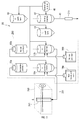
- the measuring unit 20 includes a dispensing part 200, detecting part 250, conductivity measuring part 275, and controller 280.
- the dispensing part 200 suctions sample from the sample container 15 which was moved to the sample suctioning position 15a, and dispenses the sample in the sample container 15 to the processing chambers 11a and 11b.
- the detecting part 250 detects information of the components in the sample.
- the detecting part 250 includes an optical detector 260 and a signal processing circuit 270.
- the optical detector 260 performs optical detection on the sample.
- the signal processing circuit 270 processes the signals output from the optical detector 60, and sends the processed signals to the controller 280.
- the conductivity measuring part 275 measures the conductivity of the sample and outputs the measurement to the controller 280.
- the controller 280 controls each part of the measuring unit 20, and communicates with the analyzing part 30.
- the controller 280 sends the information output from the detecting part 250 and the conductivity measuring circuit 275 to the analyzing part 30.
- the controller 280 is configured by a microcomputer.
- the analyzing part 30 analyzes the information of the components detected by the detecting part 250 and the conductivity of the sample measured by the conductivity measuring part 275.
- the components in the sample analyzed by the analyzing part 30 are, for example, material components of urine.
- Material components of urine include, for example, red blood cells, white blood cells, epithelial cells, casts, bacteria, atypical cells, and white blood cell aggregate.
- the conductivity itself is output from the analyzing part as the analysis result. Conductivity can be used to correct other analysis results.
- the analyzing part 30 is configured by a computer which has a CPU and memory.
- a computer program for analyzing the output of the detecting part 250 and the conductivity measuring part 275 is installed in the analyzing part 30.
- the measuring unit 20 also has a preparing part 290 for preparing a measurement sample from a sample.
- the preparing part 290 respectively mixes the urine sample and reagent in a plurality of processing chambers 11 a and 11b to which urine sample is dispensed by the dispensing part 200.
- the plurality of processing chambers 11a and 11b include a first processing chamber 11a which performs processing to prepare a first measurement sample, and a second processing chamber 11b which performs processing to prepare a second measurement sample.
- the number of processing chambers also may be three or more.
- the first measurement sample is obtained by mixing the sample and first reagents 15a and 14a in the first processing chamber 11a.
- the first reagents 15a and 14a are, for example, diluting liquid 15a and stain 14a.
- the stain 14a includes a fluorescent dye which stains material components that do not contain nucleic acid.
- the first measurement sample is used to analyze particles that do not contain nucleic acid, such as red blood cells and casts in urine.
- the second measurement sample is obtained by mixing the sample and second reagents 15b and 14b in the second processing chamber 11b.
- the second reagents 15b and 14b are, for example, diluting liquid 15b and stain 14b.
- the stain 14b includes dye which stains nucleic acid.
- the material components in the urine sample are stained by the stain 14b.
- the second measurement sample is used to analyze cells which contain nucleic acid, such as white blood cells, skin cells, fungi, bacteria, and atypical cells in urine.
- the first processing chamber 11a and second processing chamber 11b are connected by a sample delivery path 291 to the flow cell 261 which has the optical detector 260.
- the first measurement sample is supplied from the first processing chamber 11a to the flow cell 261 through the sample delivery path 291.
- the second measurement sample is supplied from the second processing chamber 11b to the flow cell 261 through the sample delivery path 291.
- the supplied measurement sample flows through the interior of the flow cell 261.
- the measurement samples are supplied to the flow cell 261 with the first measurement sample being first and the second measurement sample following after the first measurement sample.
- the supplying of the measurement samples from the processing chambers 11a and 11b to the flow cell 261 is performed by the controller 280 controlling a pressure source and valves which are not shown in the drawing.
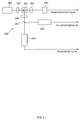
- the optical detector 260 is provided with a light irradiating part 263, and plurality of light receiving parts 265, 268, 269, in addition to the flow cell 261.
- the light irradiating part 263 is configured by, for example, a semiconductor laser light source.
- the light irradiating part 263 irradiates laser light on the measurement sample flowing through the flow cell 261.
- the plurality of light receiving parts 265, 268, 269 include a first scattered light receiving part 265, second scattered light receiving part 268, and fluorescent light receiving part 269.
- the light receiving parts 265, 268, 269 receive light given off from the components in the measurement sample which is irradiated by light.
- the optical detector 260 is further provided with a condenser lens 262, collective lenses 264 and 266, and dichroic mirror 267.
- the condenser lens 262 collects the laser light emitted from the light irradiating part 263, and forms a beam spot on the measurement sample in the flow cell 261.
- the collective lens 264 collects the forward scattered light given off by the material components in the measurement sample into the first scattered light receiving part 265.
- the collective lens 266 collects the side scattered light and fluorescent light given off by the material components into the dichroic mirror 267.
- the dichroic mirror 267 reflects the side scattered light toward the second scattered light receiving part 268, and transmits the fluorescent light toward the fluorescent light receiving part 269.
- the light receiving parts 265, 268, and 269 convert the received optical signals to electrical signals.
- the first scattered light receiving part 265 outputs forward scattered light signals
- the second scattered light receiving part 268 outputs side scattered light signals
- the fluorescent light receiving part 269 outputs fluorescent light signals.
- Each signal represents temporal changes of the intensity of the light.
- Each signal is supplied to the signal processing circuit 270 shown in FIG. 1 through an amplifier and A/D converter (not shown in the drawing).
- the signal processing circuit 270 extracts characteristics parameters from each signal to be used in the analysis process performed by the analyzing part 30.
- the characteristics parameters include, for example, forward scattered light intensity, forward scattered light pulse width, side scattered light intensity, fluorescent light intensity, fluorescent light pulse width, and fluorescent light pulse area.
- the characteristics parameters are sent to the analyzing part 30 through the controller 280.
- the measuring unit 20 also is provided with a holding chamber 17 which temporarily holds the sample until the sample suctioned from the sample container is dispensed to the processing chambers 11a and 11b, a first wash tank 18 for washing the first nozzle 111, a second wash tank 19 for washing the second nozzle 121, and a wash liquid supplier 40 for supplying wash liquid to the holding chamber 17.
- the wash liquid supplier 40 also supplies wash liquid to the first wash tank 18 and the second wash tank 19.
- the wash liquid supplier 40 also supplies wash liquid to other locations which require washing, such as the first processing chamber 11a and the second processing chamber 11b.
- the previously mentioned conductivity measuring part 275 is connected to the holding chamber 17 through a flow path 41. During conductivity measurement of a sample, the sample held in the holding chamber 17 is drawn to the conductivity measuring part 275.
- the dispensing part 200 is provided with a first unit 110 and second unit 120 for dispensing the sample suctioned from the sample container 15 into the plurality of processing chambers 11a and 11b.
- the first unit 110 includes a first nozzle 111 for suctioning and discharging a sample, and a first drive part 112 for moving the first nozzle 111.
- the second unit 120 includes a second nozzle 121 for suctioning and discharging a sample, and a second drive part 122 for moving the second nozzle 121.
- the first drive part 112 ands second drive part 122 are controlled by the controller 280.
- the first nozzle 111 has an inlet 111a on the bottom end, such that sample is suctioned from the sample container 15,and the suctioned sample is discharged from the inlet 111a into the holding chamber 17.
- the sample container 15 is held in a sample rack 16.
- the sample rack 16 is transported by a transport device which is not shown in the drawing, so that the sample container 15 is moved to the sample suction position 15a.
- the first nozzle 111 can suction sample from the sample container 15 disposed at the sample suction position 15a.
- the measuring unit 20 of FIG. 1 also has an urgent sample suction position 15b at which an urgent sample container may be set, and the first nozzle 111 can suction sample from the sample container 15 disposed at the urgent sample suction position 15b when a sample container is set at the urgent sample suction position 15b.
- the first drive part 112 includes a first horizontal mover 113 which moves the first nozzle 111in horizontal directions, and a first vertical mover 114 which moves the first nozzle 111 in vertical directions.
- the first horizontal moving device 113 has en endless belt 113b wound around a pair of pulleys 113a.
- the first vertical mover 114 is mounted on the endless belt 113a through an attachment 115.
- the first nozzle 111 is provided on the first vertical mover 114.
- the pulley 113a is driven to rotate by a motor 113c.
- the motor 113c is controlled by the controller 280.
- the endless belt 113b rotates and the first vertical mover 114 and the first nozzle 111 move in a first horizontal direction, that is, the Y1 direction or the Y2 direction.
- the Y1 direction is the front part of the sample analyzer 10
- the Y2 direction is the back part of the sample analyzer 10.
- the Y1 direction and the Y2 direction are collectively referred to as the Y direction.
- the Y direction is the front and back direction of the sample analyzer 10.
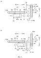
- the first vertical mover 114 has en endless belt 114b wound around a pair of pulleys 114a, as shown in FIG. 4(a) .
- a first nozzle holder 117 for holding the first nozzle 111 is mounted on the endless belt 114b through an attachment 116.
- the pulley 114a is driven to rotate by a motor 114c.
- the motor 114c is controlled by the controller 280.
- the endless belt 114b rotates and the first nozzle 111 held by the first nozzle holder 117 moves in a vertical direction, that is, the Z1 direction or Z2 direction.
- the Z1 direction is the lower part of the sample analyzer 10
- the Z2 direction is the upper part of the sample analyzer 10.
- the Z1 direction and the Z2 direction are collectively referred to as the Z direction.
- the Z direction is the up and down direction of the sample analyzer 10.
- the second nozzle 121 has an inlet 121a on the bottom end, such that sample is suctioned from the holding chamber 17,and part of the suctioned sample is discharged from the inlet 121 a into the first processing chamber 11a, and another part of the suctioned sample is discharged into the second processing chamber 11b. Accordingly, part of the sample is used in the process of preparing the first measurement sample, and another part of the sample is used in the process of preparing the second measurement sample among the entire amount of the sample separately discharged twice from the second nozzle 121.
- the second drive part 122 includes a second horizontal mover 123 which moves the second nozzle 121 in horizontal directions, and a second vertical mover 124 which moves the second nozzle 121 in vertical directions.
- the second horizontal mover 123 has en endless belt 123b wound around a pair of pulleys 123a.
- the second vertical mover 124 is mounted on the endless belt 123a through an attachment 125.
- the second nozzle 121 is provided on the second vertical mover 124.
- the pulley 123a is driven to rotate by a motor 123c.
- the motor 123c is controlled by the controller 280.
- the endless belt 123b rotates and the second vertical mover 124 and the second nozzle 121 move in a second horizontal direction, that is, the X1 direction or the X2 direction.
- the X1 direction is on the right side viewed from the front of the sample analyzer 10
- the X2 direction is on the left side viewed from the front of the sample analyzer 10.
- the X direction is the side to side direction of the sample analyzer 10.
- the second vertical mover 124 has en endless belt 124b wound around a pair of pulleys 124a, as shown in FIG. 4(b) .
- a second nozzle holder 127 for holding the second nozzle 121 is mounted on the endless belt 124b through an attachment 126.
- the pulley 124a is driven to rotate by a motor 124c.
- the motor 124c is controlled by the controller 280.
- the endless belt 124b rotates and the second nozzle 121 held by the second nozzle holder 127 moves in a vertical direction, that is, the Z1 direction or Z2 direction.
- first drive part 112 and second drive part 122 move the nozzles 111 and 121 by a belt drive system
- the nozzles 111 and 121 also may be moved by another drive system.
- Examples of other drive systems are systems that have a mechanism for moving by rotation of a screw shaft, or systems that have a mechanism for running a rotationally driven roller on a guide rail.
- the sample suctioning position 15a at which the sample container 15 is set, the holding chamber 17, and the first wash tank 18 are arranged on a straight line in the front to back Y direction.
- the urgent sample suctioning position 15b is arranged at a position extended in the front direction on a straight line from the holding chamber 17 and sample suctioning position 15a.
- the holding chamber 17 is arranged at a position nearer the sample suctioning position 15a at which the sample container 15 is set than the first wash tank 18.
- the first nozzle 111 can move to the position of the sample suctioning position 15a, urgent sample suctioning position 15b, holding chamber 17, and first wash tank 18by the first horizontal mover 113.
- a first moving path 301 of the first nozzle 111 by the first horizontal mover 113 is a straight line path along the Y direction.
- the first moving path 301 also may be a curved path.
- the first nozzle 111 can rapidly move from the position of the sample container 15 to the position of the holding chamber 17 since the holding chamber 17 is arranged at a position near the sample suctioning position 15a.
- the first vertical mover 114 lifts the first nozzle 111 to the position of the sample suctioning position 15a at which the sample container 15 is set, the holding chamber 17, and the first wash tank 18, as shown in FIG. 6 . Although omitted in FIG. 6 , the first vertical mover 114 can lift the first nozzle 111 in the Z direction at the urgent sample suctioning position 15b.
- the first nozzle 111 enters the sample container 15, holding chamber 17, or first wash tank 18 by descending.
- the first nozzle 111 retracts from the sample container 15, holding chamber 17, or first wash tank 18 by ascending.
- the movement of the first nozzle 111 shown in FIG. 6 is performed by the controller 280 controlling the first drive part 112.
- the second wash tank 19, first processing chamber 11a, and second processing chamber 11b are aligned on a straight line in the X direction which intersects the Y direction with the holding chamber 17 as the starting point.
- the second wash tank 19 is arranged at a position nearer the holding chamber 17 than either of the plurality of processing chambers 11a and 11b.
- the second nozzle 121 can be prevented from passing above the processing chambers 11a and 11b. Wash liquid may adhere and remain on the second nozzle 121 after washing in the second wash tank 19. Therefore, there is concern that the wash liquid may contaminate the processing chamber 11 a and 11b when the second nozzle 121 passes over the processing chambers 11a and 11b.
- wash liquid on the second nozzle 121 is prevented from contaminating the processing chambers 11a and 11b.
- the first processing chamber 11a is provided on the X2 side from the second processing chamber 11b.
- the second nozzle 121 can move to the position of the holding chamber 17, second wash tank 19, first processing chamber 11a and second processing chamber 11b by the second horizontal mover 123.
- a second moving path 302 of the second nozzle 121 by the second horizontal mover 123 is a straight line path along the X direction.
- the second moving path 302 also may be a curved path.
- the second moving path 302 intersects the first moving path 301 at the position of the holding chamber 17. In other words, the holding chamber 17 is arranged at the position of intersection of the first moving path 301 and the second moving path 302. Therefore, sample is easily dispensed through coordination of the first nozzle 111 and second nozzle 121.
- both paths 301 and 302 are straight line paths and compact since they are perpendicular.
- the second vertical mover 124 raises the second nozzle 121 in the Z direction to the positions of the holding chamber 17, second wash tank 19, second processing chamber 11b, and first processing chamber 11a, as shown in FIG. 6 .
- the second nozzle 121 enters inside the holding chamber 17, second wash tank 19, second processing chamber 11b, and first processing chamber 11a by descending.
- the second nozzle 121 is retracted from the holding chamber 17, second wash tank 19, second processing chamber 11b, and first processing chamber 11a by ascending.
- the movement of the first nozzle 111 shown in FIG. 6 is performed by the controller 280 controlling the second drive part 122.
- the dispensing part 200 further includes a sample suctioning circuit 150 for suctioning the sample through the first nozzle 111, and a dispensing circuit 180 for dispensing the sample to the processing chambers 11a and 11b through the second nozzle 121, as shown in FIG. 7 .
- the sample suctioning circuit 150 and dispensing circuit 180 are configured as fluid circuits.
- the fluid circuit of the embodiment is a pneumatic circuit.
- the sample suctioning circuit 150 includes a first pressure source 151, a first flow path 161 from the first nozzle 111 to the first pressure source 151, and a second flow path 162 which branches off from the first flow path 161.
- the first pressure source 151 is, for example, a syringe pump.
- the dispensing circuit 180 includes a pressure source 153, and a third flow path 163 from the second nozzle 121 to the pressure source 153.
- the pressure source 153 is, for example, a syringe pump.
- the first nozzle 111 of the embodiment is configured to integratedly have a suctioning nozzle 111b and mixing nozzle 111c.
- the suctioning nozzle 111b and mixing nozzle 111c respectively have suction ports 111a and 111d at the lower end, and are respectively capable of suctioning and discharging sample from the suction ports 111 a and 111d.
- the previously mentioned first flow path 161 is connected to the suction nozzle 111b.
- the sample suctioning circuit 150 is also provided with a second pressure source 152, and a fourth flow path 164 from the mixing nozzle 111c to the second pressure source 152.
- the second pressure source 152 is, for example, a diaphragm pump.
- the second flow path 162 shown in FIG. 7 is a bypass path which branches from the first flow path 161 at a first position 161 a of the first flow path 161, and conjoins the first flow path 161 at a second position 161b on the first pressure source 151 side from the first position 161a.
- a filter 154 for capturing foreign matter is provided between the first position 161a and 161b in the first flow path 161. Foreign matter in the urine sample suctioned from the suction nozzle 111b can be captured by the filter 154. Foreign matter contaminating a urine sample may include tissue paper fragments, pubic hair and the like.
- a first valve 155a is provided between the first position 161a and second position 161b of the first flow path 161.
- a second valve 155b is provided in the second flow path 162.
- the first valve 155a and the second valve 155b are, for example, solenoid valves.
- the first valve 155a and the second valve 155b switch the flow of sample being suctioned/discharged by the suction nozzle 111b.
- the operation of the first valve 155a and second valve 155b, and operation of the pressure sources 151, 152, and 153 is controlled by the controller 280.
- the first valve 155a is in an open state when degaussed and in a closed state during excitation.
- the second valve 155b is in a closed state when degaussed and in an open state during excitation.
- Both valves 155a and 155b are degaussed when a urine sample is suctioned from a sample container 15.
- the urine sample is suctioned from the suction nozzle 111b by the suction pressure generated by the first pressure source 151.
- the suctioned urine sample is drawn through the first flow path 161 which has the open first valve 155a to the first pressure source 151 side and not the second flow path 162 which has the closed second valve 155b.
- the entirety of the suctioned urine sample moves past the second position 161b to the first pressure source 151 side. Since the suctioned urine sample passes through the filter 154 provided in the first flow path 161, foreign matter is captured by the filter 154.
- Both valves 155a and 155b are excited when the suctioned urine sample is being discharged.
- the sample which has passed through the filter 154 and is between the second position 161b and the first position 161a is discharged from the suction nozzle 111b by the discharge pressure generated by the first pressure source 151.
- the sample bypasses the filter 154 by passing through the second flow path 162 which has the open second valve 155b and not through the first flow path 161 which has the closed first valve 155a.
- foreign matter captured by the filter 154 is prevented from being discharged from the nozzle 111b along with the urine sample by bypassing the filter 154.
- the mixing nozzle 111 c mixes the sample in the sample container 15 before the urine sample is suctioned from the sample container 15.
- the sample is allowed to flow from the mixing nozzle 111c to the fourth flow path 164 by the suction pressure generated by the second pressure source 152, then the sample in the fourth flow path 164 is again returned from the mixing nozzle 111c to the sample container 15 by the discharge pressure generated by the second pressure source 152.
- the sample is thoroughly mixed by the repeated suction and discharge by the mixing nozzle 111c.
- the fourth flow path 164 is a formed as a wider flow path than the first flow path 161 and second flow path 162.
- a diaphragm pump is used as the second pressure source 152 in the embodiment.
- the diaphragm pump 152 can perform the mixing in a short time since its suction and discharge speeds are faster and several suctions and discharges can be performed quickly.
- the dispensing circuit 180 suctions the sample in the holding chamber 17 through the second nozzle 121, and dispenses the suctioned sample to the processing chambers 11a and 11b.
- the sample in the holding chamber 17 is allowed to flow from the second nozzle 121 to the third flow path 163 by the suction pressure generated by the pressure source 153. Thereafter, the sample in the third flow path 163 is discharged to the plurality of processing chambers 11 a and 11b by the discharge pressure generated by the pressure source 153.
- the dispensing circuit 180 does not require a filter 154 to capture foreign matter in the third flow path 163 since the sample is suctioned after the foreign matter has been removed. That is, the third flow path 163 is a filterless flow path.
- the second nozzle 121 is configured to have an internal diameter that is smaller than the flow path diameter within the suctioning nozzle 111a of the first nozzle 111. Sample possibly containing foreign matter can be efficiently suctioned by enlarging the suctioning nozzle 111a. However, a precise amount of sample can be obtained by narrowing the second nozzle 121. The second nozzle 121 has a low possibility of becoming clogged by foreign matter even if narrowed because foreign matter has been removed from the sample to be suctioned and discharged.
- sample dispensation is performed by the first nozzle 111 and second nozzle 121; however, since the operation related to the first nozzle 111and the operation related to the second nozzle 121 are performed with overlapping timing it is possible to reduce the time required for sample processing.
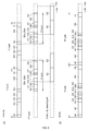
- the operation related to the first nozzle 111 and the operation related to the second nozzle 121 are described below referring to FIG. 9 through FIG. 12 .
- the controller 280 performs controls of the first drive part 112, second drive part 122, pressure sources 151, 152, and 153, valves 155a, 155b and the like.
- the first nozzle 111 and second nozzle 121 are positioned at the initial positions shown in FIG. 9(a) .
- the first nozzle 111 is positioned above the first wash tank 18, and the second nozzle is positioned above the second wash tank 19. Note that in FIG. 6 the initial position of the first nozzle 111 is represented by the symbol 301a, and the initial position of the second nozzle 121 is represented by the symbol 302a.
- Step S11 includes steps S11a and S11b shown in FIG. 6 .
- step S11a the first drive part 112 moves the first nozzle 111 forward in the Y1 direction, and positions the first nozzle 111 above the sample container 15 which is set at the sample suction position 15a, as shown in FIG. 9(b) .
- step S11b the first nozzle 111 descends and enters the sample container 15.
- step S12 shown in FIG. 8(a) is performed.
- step S12 the sample within the sample container 15 is suctioned and discharged by the mixing nozzle 111 c by the pressure source connected to the mixing nozzle 111c of the first nozzle 111.
- the sample can be mixed within the sample container in this way.
- the sample within the sample container 15 is suctioned by the suction nozzle 111b by the pressure source connected to the suction nozzle 111b of the first nozzle 111.
- the amount of sample suctioned by the suction nozzle 111b is, for example, 450 ⁇ L.
- Step S 13 includes steps S13a, S13b, and S13c shown in FIG. 6 .
- step S13a the first nozzle 111 is raised and retracted from the sample container 15.
- step S13b the first drive part 112 moves the first nozzle 111 backward in the Y2 direction, and positions the first nozzle 111 above the holding chamber 17, as shown in FIG. 10(a) .
- step S13c the first nozzle 111 descends and enters the holding chamber 17.
- step S14 shown in FIG. 8(a) is performed.
- step S 14 the total amount of suctioned sample is discharged from the suction nozzle 11b of the first nozzle 111 into the holding chamber 17 by the pressure source 151.
- the second nozzle 121 is positioned above the second wash tank 19 and does not inhibit the movement of the first nozzle 111 above the first moving path 301.
- Step S15 includes steps S15a, S15b, and S15c shown in FIG. 6 .
- step S 15a the first nozzle 111 is raised and retracted from the holding chamber 17.
- step S15b the first horizontal mover 113 moves the first nozzle 111 backward in the Y2 direction and positions the first nozzle 111 above the first wash tank 18, as shown in FIG. 10(b) .
- step S 15c the first nozzle 111 descends and enters the first wash tank 18.
- step S16 shown in FIG. 8(a) is performed.
- step S16 the first nozzle 111 is washed in the first wash tank 18 by the wash liquid supplied from the wash liquid supplier 40.
- the controller 280 performs controls to move the first nozzle 111 to the position of the first wash tank 18 by the first drive part 112 and then wash the first nozzle 111 in the first wash tank 18 after the first nozzle 111 has discharged the sample into the holding chamber 17.
- the first nozzle 111 is raised and returned to the initial position 301a, and the standby state shown in FIG. 9(a) is restored in step S17.
- Steps S11 through S 17 above are a first cycle of sample suctioning and discharging performed by the first nozzle 111. After the first cycle, a second cycle is executed to suction the sample of the next sample container 15.
- Step S21 in which the second nozzle 121 moves to the position of the holding chamber 17 is performed without waiting for the completion of step S16 in which the first nozzle 111 is washed.
- Step S21 includes steps S21a and S21 b shown in FIG. 6 .
- Step S21a begins when the first nozzle 111 starts moving to the first wash tank 18 in step S 15.
- step S21a the second drive part 122 moves the second nozzle 121 to the right in the X1 direction, and positions the second nozzle 121 above the holding chamber 17, as shown in FIG. 10(b) . Then, in step S21b the second nozzle 121 descends and enters the holding chamber 17. In this state, step S22 shown in FIG. 8(a) is performed. Step S22 begins at substantially the same time with the start of washing of the first nozzle 111 in step S16. In step S22, part of the sample in the holding chamber 17 is suctioned from the second nozzle 121 by the pressure source 153 connected to the second nozzle 121. The amount of sample suctioned by the second nozzle 121 is, for example, 250 ⁇ L.
- step S22 part of the suctioned sample is discharged into the holding chamber 17 after sample is suctioned by the second nozzle 121, and the condition of sample filling to the bottom end of the second nozzle 121 is obtained in this way. Therefore, dispensing to the processing chambers 11 a and 11 b is performed more accurately.
- Step S23 includes steps S23a, S23b, and S23c shown in FIG. 6 .
- step S23a the second nozzle 121 is raised and retracted from the holding chamber 17.
- step S23b the second drive part 122 moves the second nozzle 121 to the left in the X2 direction, and positions the second nozzle 121 above the first processing chamber 11a, as shown in FIG. 10(c) .
- step S23c the second nozzle 121 descends and enters the first processing chamber 11a. In this state, step S24 shown in FIG.
- step S24 part of the sample suctioned by the second nozzle 121 is discharged from the second nozzle 121 into the first processing chamber 11a by the pressure source 153.
- the amount of sample discharged into the first processing chamber 11a is, for example, 125 ⁇ L.
- the dispensed sample is mixed with first reagents 15a and 14a to prepare a first measurement sample.
- Step S25 includes steps S25a, S25b, and S25c shown in FIG. 6 .
- step S25a the second nozzle 121 is raised and retracted from the first processing chamber 11a.
- step S25b the second drive part 122 moves the second nozzle 121 to the right in the X1 direction, and positions the second nozzle 121 above the second processing chamber 11b, as shown in FIG. 11(a) .
- the second nozzle 121 briefly waits at a position above the second processing chamber 11b.
- step S25c the second nozzle 121 descends and enters the second processing chamber 11b.
- step S26 shown in FIG. 8(a) is performed.
- step S26 another part of the sample suctioned by the second nozzle 121 is discharged from the second nozzle 121 into the second processing chamber 11b by the pressure source 153.
- the amount of sample discharged into the second processing chamber 11b is, for example, 125 ⁇ L.
- the dispensed sample is mixed with second reagents 15band 14b to prepare a second measurement sample.
- the controller 280 performs controls to move the second nozzle 121 to the plurality of processing chambers 11a and 11b by the second drive part 122 and then discharge part of the sample from the second nozzle 121 into the respective plurality of processing chambers 11a and 11b during the time after the start of movement by the first nozzle 111 to the position of the first wash tank 18 until the first nozzle 111 suctions sample from the next sample container 15.
- the suctioning of sample from the holding chamber 17 by the second nozzle 121 is performed in parallel with the washing of the first nozzle 111 in step S16 shown in FIG. 8 .
- moving the second nozzle 121 to the first processing chamber 11a in step S23, dispensing into the first processing chamber 11a by the second nozzle 121 in step S24, and moving the second nozzle 121 in steps S25a and S25b, are performed during step S16. Therefore, at least part of the operation of dispensing sample to the plurality of processing chambers 11a and 11 b is performed while the first nozzle 111 is being washed in step S16.
- the first nozzle 111 is on standby at the initial position 301 a above the first wash tank 18 until suctioning sample from the next sample container 15 in step S 17 after the first nozzle 111 is washed in step S16.
- the remaining operations of dispensing sample to the plurality of processing chambers 11 a and 11b are performed in step S 17. That is, moving the movement of the second nozzle 121 in step S25c and dispensing by the second nozzle 121 into the second processing chamber 11b in step S26 are performed during step S17.
- the above parallel processing is performed during the time taken to wash the first nozzle 111in step S16. Contamination of the next sample suctioned by the first nozzle 111 is more reliably prevented by taking time to wash the first nozzle 111.
- re-passing the second nozzle 121 over the processing chamber to which sample has already been discharged is prevented by performing the discharge from the second nozzle 121 into the plurality of processing chamber 11a and 11b with the first discharge to the processing chamber 11a which is positioned farthest from the holding chamber 17.
- the second nozzle 121 when sample is discharged to the first processing chamber 11a after first discharging sample to the second processing chamber 11b, the second nozzle 121 must re-pass over the second processing chamber 11b after discharging sample to the first processing chamber 11a. At this time there is a possibility that a slight residual sample remaining on the second nozzle 121 may fall into the second processing chamber 11b. However, such an occurrence can be prevented by discharging sample from the second nozzle 121 first to the processing chamber 11a which is positioned farthest from the holding chamber 17.
- Step S27 includes steps S27a, S27b, and S27c shown in FIG. 6 .
- step S27a the second nozzle 121 is raised and retracted from the second processing chamber 11b.
- step S27b the second drive part 122 moves the second nozzle 121 to the right in the X1 direction, and positions the second nozzle 121 above the second wash tank 19, as shown in FIG. 11(b) .
- step S27c the second nozzle 121 descends and enters the second wash tank 19.
- step S28 shown in FIG. 8(a) is performed.
- step S28 the second nozzle 121 is washed in the second wash tank 19 by the wash liquid supplied from the wash liquid supplier 40.
- the controller 280 performs controls to move the second nozzle 121 to the position of the second wash tank 19 by the second drive part 122 and wash the second nozzle 121 in the second wash tank 19 after the second nozzle 121 has discharged the sample into the plurality of processing chambers 11a and 11b.
- the washing of step S28 ends, the second nozzle 121 is raised and returned to the initial position 302a, and the standby state shown in FIG. 9(a) is restored, in step S29.
- Steps S21 through S29 above are a first cycle of sample suctioning and discharging performed by the second nozzle 121. After the first cycle, a second cycle is executed to suction the sample of the next sample container 15 which is held in the holding chamber 17.
- controls are executed to move the first nozzle 111 to the next sample container 15, suction the next urine sample, and discharge the suctioned sample into the holding tank 17 after the second nozzle 121 has been moved to the second wash tank 19.
- washing of the second nozzle 121 in step S28 and step S12 of the second cycle pertaining to the sample of the next sample container 15 are performed with overlapping timing. This occurs during the time of washing the second nozzle 121 in step S28. Contamination of the next sample suctioned by the second nozzle 121 is more reliably prevented by taking time to wash the second nozzle 121.
- the time required for sample processing is increased as shown in FIG. 8(b) when sample is dispensed from the sample container 15 to the processing chambers 11a and 11b using a single nozzle and the dispensing part 200 does not have the plurality of nozzles 111 and 121 and holding chamber 17 of the embodiment. That is, when sample is suctioned from the sample container 15 and sample is discharged to the processing chambers 11 a and 11b by a single nozzle, suctioning of the sample contained in the next sample container 15 cannot be performed until completion of washing the nozzle following sample discharge into the processing chambers 11a and 11b.
- An example of the sample processing sequence when using a single nozzle is shown in FIG. 8(b) . In FIG.
- step S41 the nozzle is moved from the initial position to the sample suction position in step S41.
- the operation performed in step S41 is identical to the operation performed in step S 11.
- step S42 sample is suctioned by the nozzle.
- the operation performed in step S42 is identical to the operation performed in step S12.
- step S43 the nozzle is moved to the wash tank.
- step S44 part of the suctioned sample is discharged from the nozzle into the wash tank to fill the bottom of the nozzle with sample.
- step S45 to step S49 the nozzle is moved to the position of the processing chamber and discharges sample into the processing chamber, then is moved to the position of the wash tank.
- the operations of steps S45 through S49 are identical to the operations of steps S23 through S27.
- step S50 the nozzle is washed in the wash tank, and returned to the initial position in step S51.
- the operations of steps S50 and S51 are identical to the operations of steps S16 and 517.
- Steps S41 through S51 above are a first cycle of sample suctioning and discharging performed by the single nozzle. After the first cycle, a second cycle is executed to suction the sample of the next sample container 15. In the example of FIG.
- step S41 of the second cycle cannot be executed until step S50 of the first cycle is completed.
- step S50 of the first cycle is completed.
- the time is reduced since the first nozzle 111 also discharges sample to a single holding chamber 17 which is disposed near the position of the sample container 15 after the sample nozzle 111 has suctioned sample from the sample container 15 in step S 11, compared to dispensing to a plurality of processing chambers 11a and 11b.
- the discharged sample enters the sample container.
- the sample suctioned by the nozzle which does not temporarily enter the sample container is suitable for separate analysis.
- steps S43 and S44 are unnecessary due to the partial discharge of sample into the holding chamber 17 in step S22 of the embodiment.
- step S31 of FIG. 8(a) the sample remaining in the holding chamber 17 is drawn to the conductivity measuring part 275 through the flow path 41, and the conductivity of the sample is measured. Since the conductivity of the urine sample is used to determine the specific gravity of the urine, a suitable conductivity can be determined by measuring the original sample before the sample is mixed with a reagent, and not a measurement sample to which reagent has been added.
- the holding chamber 17 is washed by wash liquid supplied from the wash liquid supplier 40 in step S32.
- the next sample can be discharged from the first nozzle 111 to the holding chamber 17.
- the layout of the holding chamber, processing chambers, and wash tanks is not limited to the layout shown in FIG. 6 inasmuch as the layout shown in FIG. 12 is also possible.
- the first moving path 301 and second moving path 302 are T-shaped in entirety in FIG. 6
- the first moving path 301 and second moving path 302 are L-shaped shown in FIG. 12(a) .
- the first moving path 301 and second moving path 302 are perpendicular, and the holding chamber 17 is disposed at the intersection of the first moving path 301 and second moving path 302.
- the first wash tank 18 is disposed between the sample container 15 and the holding chamber 17.
- the distance is increased between the sample container 15 and the holding chamber 17.
- the first moving path 301 and second moving path 302 shown in FIG. 12(b) are cross-shaped.
- the second wash tank 19 is disposed on the right side, that is, on the X1 direction side of the holding chamber 17, and not between the holding chamber 17 and the second processing chamber 11b.
- the first moving path 301 and second moving path 302 shown in FIG. 12(c) is T-shaped identically to FIG. 6 .
- the second wash tank 19 is disposed at a position farther from the processing chambers 11a and 11b viewed from the holding chamber 17.
Landscapes
- Health & Medical Sciences (AREA)
- Chemical & Material Sciences (AREA)
- Life Sciences & Earth Sciences (AREA)
- Physics & Mathematics (AREA)
- Analytical Chemistry (AREA)
- General Health & Medical Sciences (AREA)
- Immunology (AREA)
- Biochemistry (AREA)
- Pathology (AREA)
- General Physics & Mathematics (AREA)
- Engineering & Computer Science (AREA)
- Biomedical Technology (AREA)
- Urology & Nephrology (AREA)
- Medicinal Chemistry (AREA)
- Hematology (AREA)
- Molecular Biology (AREA)
- Food Science & Technology (AREA)
- Chemical Kinetics & Catalysis (AREA)
- Clinical Laboratory Science (AREA)
- Biophysics (AREA)
- Dispersion Chemistry (AREA)
- Hydrology & Water Resources (AREA)
- Automatic Analysis And Handling Materials Therefor (AREA)
Abstract
Description
- The invention relates to a urine sample analyzer and urine sample dispensing method.
- United States Patent Application Publication No.
2014/322802 discloses a device in which a single sampling nozzle suctions and discharges sample in order to dispense the sample. - When measuring a plurality of samples, the nozzle must be washed each time the nozzle finishes suctioning and discharging a sample to prevent mutual contamination of samples. United States Patent Application Publication No.
2014/322802 also discloses washing the sampling nozzle which has finished dispensing a sample. - However, when the nozzle is washed, the nozzle cannot suction the next sample until the washing of the nozzle is completed. As a result, when measuring a plurality of samples, more time is required until the measurement results for the plurality of sample is reported due to the waiting time for washing the nozzle.
- The scope of the present invention is defined solely by the appended claims, and is not affected to any degree by the statements within this summary.
- One aspect of the invention relates to a urine sample analyzer. The analyzer comprises: a holding chamber for holding a urine sample; a first nozzle for suctioning a urine sample from a sample container and discharging the suctioned urine sample into the holding chamber; a first wash tank for washing the first nozzle; a plurality of processing chambers for receiving and processing a urine sample; a second nozzle for suctioning the urine sample from the holding chamber and respectively discharging a part of the suctioned urine sample to the plurality of holding chambers; and a controller. The controller is configured to perform operations for: moving the first nozzle to the first wash tank and washing the first nozzle in the first wash tank after the first nozzle has discharged a urine sample into the holding chamber; and moving the second nozzle to the holding chamber after the first nozzle has started moving from the holding chamber to the first wash tank, moving the second nozzle which has suctioned the urine sample from the holding chamber to the respective plurality of processing chambers, and discharging a part of the urine sample from the second nozzle into the respective plurality of processing chambers. The analyzer further comprises: a detector for detecting information of material components in the urine samples respectively processed in the plurality of processing chambers; and an analyzing part for analyzing the information of the material components detected by the detector.
- Another aspect of the invention relates to a sample dispensing method. The method comprises: suctioning a urine sample from a sample container by a first nozzle;
moving the first nozzle to a holding chamber after the first nozzle has suctioned the urine sample from the sample container, and discharging the urine sample into the holding chamber; moving the first nozzle to a first wash tank and washing the first nozzle in the first wash tank after the first nozzle has discharged the urine sample into the holding chamber; and moving a second nozzle to the holding chamber after the first nozzle has started moving to the first wash tank, and moving the second nozzle which has suctioned the urine sample from the holding chamber to respective plurality of processing chambers and discharging a part of the urine sample to the respective plurality of processing chambers. -
-
FIG. 1 is a structural view of the sample analyzer; -
FIG. 2 is a structural view of the preparing part; -
FIG. 3 is a structural view of the optical detecting part; -
FIG. 4 is a structural view of the first vertical mover and second vertical mover; -
FIG. 5 illustrates the layout of the holding chamber, processing chambers, and wash tanks; -
FIG. 6 illustrates the nozzle movement paths; -
FIG. 7 is a structural view of the suction circuit and dispensing circuit; -
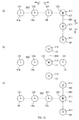
FIG. 8 is a timing sequence showing the operation of the sample analyzer; -
FIG. 9 illustrates the positions of the first nozzle and the second nozzle; -
FIG. 10 illustrates the positions of the first nozzle and the second nozzle; -
FIG. 11 illustrates the positions of the first nozzle and the second nozzle; and -
FIG. 12 illustrates the layout of the holding chamber, processing chambers, and wash tanks. - The
sample analyzer 10 shown inFIG. 1 analyzes samples such as urine samples. Thesample analyzer 10 includes ameasuring unit 20 which measures samples, and an analyzingpart 30 which analyzes the output of themeasuring unit 20. Themeasuring unit 20 includes a dispensingpart 200, detectingpart 250,conductivity measuring part 275, andcontroller 280. - The dispensing
part 200 suctions sample from thesample container 15 which was moved to thesample suctioning position 15a, and dispenses the sample in thesample container 15 to theprocessing chambers part 250 detects information of the components in the sample. The detectingpart 250 includes anoptical detector 260 and asignal processing circuit 270. Theoptical detector 260 performs optical detection on the sample. Thesignal processing circuit 270 processes the signals output from the optical detector 60, and sends the processed signals to thecontroller 280. Theconductivity measuring part 275 measures the conductivity of the sample and outputs the measurement to thecontroller 280. Thecontroller 280 controls each part of themeasuring unit 20, and communicates with the analyzingpart 30. Thecontroller 280 sends the information output from the detectingpart 250 and the conductivity measuringcircuit 275 to the analyzingpart 30. Thecontroller 280 is configured by a microcomputer. - The analyzing
part 30 analyzes the information of the components detected by the detectingpart 250 and the conductivity of the sample measured by theconductivity measuring part 275. The components in the sample analyzed by the analyzingpart 30 are, for example, material components of urine. Material components of urine include, for example, red blood cells, white blood cells, epithelial cells, casts, bacteria, atypical cells, and white blood cell aggregate. When the sample is a urine sample, the conductivity itself is output from the analyzing part as the analysis result. Conductivity can be used to correct other analysis results. - The analyzing
part 30 is configured by a computer which has a CPU and memory. A computer program for analyzing the output of the detectingpart 250 and theconductivity measuring part 275 is installed in the analyzingpart 30. - As shown in
FIG. 2 , themeasuring unit 20 also has a preparingpart 290 for preparing a measurement sample from a sample. The preparingpart 290 respectively mixes the urine sample and reagent in a plurality ofprocessing chambers part 200. The plurality ofprocessing chambers first processing chamber 11a which performs processing to prepare a first measurement sample, and asecond processing chamber 11b which performs processing to prepare a second measurement sample. The number of processing chambers also may be three or more. - The first measurement sample is obtained by mixing the sample and
first reagents first processing chamber 11a. Thefirst reagents liquid 15a andstain 14a. Thestain 14a includes a fluorescent dye which stains material components that do not contain nucleic acid. In the first measurement sample, the material components in the urine are stained by thestain 14a. The first measurement sample is used to analyze particles that do not contain nucleic acid, such as red blood cells and casts in urine. The second measurement sample is obtained by mixing the sample andsecond reagents second processing chamber 11b. Thesecond reagents liquid 15b andstain 14b. Thestain 14b includes dye which stains nucleic acid. In the second measurement sample, the material components in the urine sample are stained by thestain 14b. The second measurement sample is used to analyze cells which contain nucleic acid, such as white blood cells, skin cells, fungi, bacteria, and atypical cells in urine. - The
first processing chamber 11a andsecond processing chamber 11b are connected by asample delivery path 291 to theflow cell 261 which has theoptical detector 260. The first measurement sample is supplied from thefirst processing chamber 11a to theflow cell 261 through thesample delivery path 291. The second measurement sample is supplied from thesecond processing chamber 11b to theflow cell 261 through thesample delivery path 291. The supplied measurement sample flows through the interior of theflow cell 261. The measurement samples are supplied to theflow cell 261 with the first measurement sample being first and the second measurement sample following after the first measurement sample. The supplying of the measurement samples from theprocessing chambers flow cell 261 is performed by thecontroller 280 controlling a pressure source and valves which are not shown in the drawing. - As shown in
FIG. 3 , theoptical detector 260 is provided with alight irradiating part 263, and plurality of light receivingparts flow cell 261. Thelight irradiating part 263 is configured by, for example, a semiconductor laser light source. Thelight irradiating part 263 irradiates laser light on the measurement sample flowing through theflow cell 261. The plurality of light receivingparts light receiving part 265, second scatteredlight receiving part 268, and fluorescent light receiving part 269. Thelight receiving parts - The
optical detector 260 is further provided with acondenser lens 262,collective lenses dichroic mirror 267. Thecondenser lens 262 collects the laser light emitted from thelight irradiating part 263, and forms a beam spot on the measurement sample in theflow cell 261. Thecollective lens 264 collects the forward scattered light given off by the material components in the measurement sample into the first scatteredlight receiving part 265. Thecollective lens 266 collects the side scattered light and fluorescent light given off by the material components into thedichroic mirror 267. Thedichroic mirror 267 reflects the side scattered light toward the second scatteredlight receiving part 268, and transmits the fluorescent light toward the fluorescent light receiving part 269. - The
light receiving parts light receiving part 265 outputs forward scattered light signals, the second scatteredlight receiving part 268 outputs side scattered light signals, and the fluorescent light receiving part 269 outputs fluorescent light signals. Each signal represents temporal changes of the intensity of the light. Each signal is supplied to thesignal processing circuit 270 shown inFIG. 1 through an amplifier and A/D converter (not shown in the drawing). Thesignal processing circuit 270 extracts characteristics parameters from each signal to be used in the analysis process performed by the analyzingpart 30. The characteristics parameters include, for example, forward scattered light intensity, forward scattered light pulse width, side scattered light intensity, fluorescent light intensity, fluorescent light pulse width, and fluorescent light pulse area. The characteristics parameters are sent to the analyzingpart 30 through thecontroller 280. - Returning to
FIG. 2 , the measuringunit 20 also is provided with a holdingchamber 17 which temporarily holds the sample until the sample suctioned from the sample container is dispensed to theprocessing chambers first wash tank 18 for washing thefirst nozzle 111, asecond wash tank 19 for washing thesecond nozzle 121, and awash liquid supplier 40 for supplying wash liquid to the holdingchamber 17. Thewash liquid supplier 40 also supplies wash liquid to thefirst wash tank 18 and thesecond wash tank 19. Thewash liquid supplier 40 also supplies wash liquid to other locations which require washing, such as thefirst processing chamber 11a and thesecond processing chamber 11b. - As shown in
FIG. 2 , the previously mentionedconductivity measuring part 275 is connected to the holdingchamber 17 through aflow path 41. During conductivity measurement of a sample, the sample held in the holdingchamber 17 is drawn to theconductivity measuring part 275. - Returning to
FIG. 1 , the dispensingpart 200 is provided with afirst unit 110 andsecond unit 120 for dispensing the sample suctioned from thesample container 15 into the plurality ofprocessing chambers first unit 110 includes afirst nozzle 111 for suctioning and discharging a sample, and afirst drive part 112 for moving thefirst nozzle 111. Thesecond unit 120 includes asecond nozzle 121 for suctioning and discharging a sample, and asecond drive part 122 for moving thesecond nozzle 121. Thefirst drive part 112 ands second drivepart 122 are controlled by thecontroller 280. - The
first nozzle 111 has aninlet 111a on the bottom end, such that sample is suctioned from thesample container 15,and the suctioned sample is discharged from theinlet 111a into the holdingchamber 17. Thesample container 15 is held in asample rack 16. Thesample rack 16 is transported by a transport device which is not shown in the drawing, so that thesample container 15 is moved to thesample suction position 15a. Thefirst nozzle 111 can suction sample from thesample container 15 disposed at thesample suction position 15a. - The measuring
unit 20 ofFIG. 1 also has an urgentsample suction position 15b at which an urgent sample container may be set, and thefirst nozzle 111 can suction sample from thesample container 15 disposed at the urgentsample suction position 15b when a sample container is set at the urgentsample suction position 15b. - The
first drive part 112 includes a firsthorizontal mover 113 which moves the first nozzle 111in horizontal directions, and a firstvertical mover 114 which moves thefirst nozzle 111 in vertical directions. The first horizontal movingdevice 113 has enendless belt 113b wound around a pair of pulleys 113a. The firstvertical mover 114 is mounted on theendless belt 113a through anattachment 115. Thefirst nozzle 111 is provided on the firstvertical mover 114. Thepulley 113a is driven to rotate by amotor 113c. Themotor 113c is controlled by thecontroller 280. When thepulleys 113a are driven to rotate, theendless belt 113b rotates and the firstvertical mover 114 and thefirst nozzle 111 move in a first horizontal direction, that is, the Y1 direction or the Y2 direction. Note that the Y1 direction is the front part of thesample analyzer 10, and the Y2 direction is the back part of thesample analyzer 10. The Y1 direction and the Y2 direction are collectively referred to as the Y direction. The Y direction is the front and back direction of thesample analyzer 10. - The first
vertical mover 114 has enendless belt 114b wound around a pair of pulleys 114a, as shown inFIG. 4(a) . Afirst nozzle holder 117 for holding thefirst nozzle 111 is mounted on theendless belt 114b through anattachment 116. Thepulley 114a is driven to rotate by amotor 114c. Themotor 114c is controlled by thecontroller 280. When thepulleys 114a are driven to rotate, theendless belt 114b rotates and thefirst nozzle 111 held by thefirst nozzle holder 117 moves in a vertical direction, that is, the Z1 direction or Z2 direction. Note that the Z1 direction is the lower part of thesample analyzer 10, and the Z2 direction is the upper part of thesample analyzer 10. The Z1 direction and the Z2 direction are collectively referred to as the Z direction. The Z direction is the up and down direction of thesample analyzer 10. - The
second nozzle 121 has aninlet 121a on the bottom end, such that sample is suctioned from the holdingchamber 17,and part of the suctioned sample is discharged from theinlet 121 a into thefirst processing chamber 11a, and another part of the suctioned sample is discharged into thesecond processing chamber 11b. Accordingly, part of the sample is used in the process of preparing the first measurement sample, and another part of the sample is used in the process of preparing the second measurement sample among the entire amount of the sample separately discharged twice from thesecond nozzle 121. - The
second drive part 122 includes a secondhorizontal mover 123 which moves thesecond nozzle 121 in horizontal directions, and a secondvertical mover 124 which moves thesecond nozzle 121 in vertical directions. The secondhorizontal mover 123 has enendless belt 123b wound around a pair of pulleys 123a. The secondvertical mover 124 is mounted on theendless belt 123a through anattachment 125. Thesecond nozzle 121 is provided on the secondvertical mover 124. Thepulley 123a is driven to rotate by amotor 123c. Themotor 123c is controlled by thecontroller 280. When thepulleys 123a are driven to rotate, theendless belt 123b rotates and the secondvertical mover 124 and thesecond nozzle 121 move in a second horizontal direction, that is, the X1 direction or the X2 direction. Note that the X1 direction is on the right side viewed from the front of thesample analyzer 10, and the X2 direction is on the left side viewed from the front of thesample analyzer 10. The X direction is the side to side direction of thesample analyzer 10. - The second
vertical mover 124 has enendless belt 124b wound around a pair of pulleys 124a, as shown inFIG. 4(b) . Asecond nozzle holder 127 for holding thesecond nozzle 121 is mounted on theendless belt 124b through anattachment 126. Thepulley 124a is driven to rotate by amotor 124c. Themotor 124c is controlled by thecontroller 280. When thepulleys 124a are driven to rotate, theendless belt 124b rotates and thesecond nozzle 121 held by thesecond nozzle holder 127 moves in a vertical direction, that is, the Z1 direction or Z2 direction. - Although the
first drive part 112 andsecond drive part 122 move thenozzles nozzles - As shown in
FIG. 5 , thesample suctioning position 15a at which thesample container 15 is set, the holdingchamber 17, and thefirst wash tank 18 are arranged on a straight line in the front to back Y direction. The urgentsample suctioning position 15b is arranged at a position extended in the front direction on a straight line from the holdingchamber 17 andsample suctioning position 15a. The holdingchamber 17 is arranged at a position nearer thesample suctioning position 15a at which thesample container 15 is set than thefirst wash tank 18. Thefirst nozzle 111 can move to the position of thesample suctioning position 15a, urgentsample suctioning position 15b, holdingchamber 17, and first wash tank 18by the firsthorizontal mover 113. A first movingpath 301 of thefirst nozzle 111 by the firsthorizontal mover 113 is a straight line path along the Y direction. The first movingpath 301 also may be a curved path. - In the present embodiment, the
first nozzle 111 can rapidly move from the position of thesample container 15 to the position of the holdingchamber 17 since the holdingchamber 17 is arranged at a position near thesample suctioning position 15a. - The first
vertical mover 114 lifts thefirst nozzle 111 to the position of thesample suctioning position 15a at which thesample container 15 is set, the holdingchamber 17, and thefirst wash tank 18, as shown inFIG. 6 . Although omitted inFIG. 6 , the firstvertical mover 114 can lift thefirst nozzle 111 in the Z direction at the urgentsample suctioning position 15b. - The
first nozzle 111 enters thesample container 15, holdingchamber 17, orfirst wash tank 18 by descending. Thefirst nozzle 111 retracts from thesample container 15, holdingchamber 17, orfirst wash tank 18 by ascending. The movement of thefirst nozzle 111 shown inFIG. 6 is performed by thecontroller 280 controlling thefirst drive part 112. - Returning to
FIG. 5 , Thesecond wash tank 19,first processing chamber 11a, andsecond processing chamber 11b are aligned on a straight line in the X direction which intersects the Y direction with the holdingchamber 17 as the starting point. Thesecond wash tank 19 is arranged at a position nearer the holdingchamber 17 than either of the plurality ofprocessing chambers second wash tank 19, thesecond nozzle 121 can be prevented from passing above theprocessing chambers second nozzle 121 after washing in thesecond wash tank 19. Therefore, there is concern that the wash liquid may contaminate theprocessing chamber second nozzle 121 passes over theprocessing chambers second nozzle 121 is prevented from contaminating theprocessing chambers - The
first processing chamber 11a is provided on the X2 side from thesecond processing chamber 11b. Thesecond nozzle 121 can move to the position of the holdingchamber 17,second wash tank 19,first processing chamber 11a andsecond processing chamber 11b by the secondhorizontal mover 123. A second movingpath 302 of thesecond nozzle 121 by the secondhorizontal mover 123 is a straight line path along the X direction. The second movingpath 302 also may be a curved path. The second movingpath 302 intersects the first movingpath 301 at the position of the holdingchamber 17. In other words, the holdingchamber 17 is arranged at the position of intersection of the first movingpath 301 and the second movingpath 302. Therefore, sample is easily dispensed through coordination of thefirst nozzle 111 andsecond nozzle 121. Although the first movingpath 301 and second movingpath 302 intersect, bothpaths - The second
vertical mover 124 raises thesecond nozzle 121 in the Z direction to the positions of the holdingchamber 17,second wash tank 19,second processing chamber 11b, andfirst processing chamber 11a, as shown inFIG. 6 . Thesecond nozzle 121 enters inside the holdingchamber 17,second wash tank 19,second processing chamber 11b, andfirst processing chamber 11a by descending. Thesecond nozzle 121 is retracted from the holdingchamber 17,second wash tank 19,second processing chamber 11b, andfirst processing chamber 11a by ascending. The movement of thefirst nozzle 111 shown inFIG. 6 is performed by thecontroller 280 controlling thesecond drive part 122. - The dispensing
part 200 further includes asample suctioning circuit 150 for suctioning the sample through thefirst nozzle 111, and adispensing circuit 180 for dispensing the sample to theprocessing chambers second nozzle 121, as shown inFIG. 7 . Thesample suctioning circuit 150 and dispensingcircuit 180 are configured as fluid circuits. The fluid circuit of the embodiment is a pneumatic circuit. - The
sample suctioning circuit 150 includes afirst pressure source 151, afirst flow path 161 from thefirst nozzle 111 to thefirst pressure source 151, and asecond flow path 162 which branches off from thefirst flow path 161. Thefirst pressure source 151 is, for example, a syringe pump. The dispensingcircuit 180 includes apressure source 153, and athird flow path 163 from thesecond nozzle 121 to thepressure source 153. Thepressure source 153 is, for example, a syringe pump. - The
first nozzle 111 of the embodiment is configured to integratedly have asuctioning nozzle 111b and mixingnozzle 111c. Thesuctioning nozzle 111b and mixingnozzle 111c respectively havesuction ports suction ports first flow path 161 is connected to thesuction nozzle 111b. Thesample suctioning circuit 150 is also provided with asecond pressure source 152, and afourth flow path 164 from the mixingnozzle 111c to thesecond pressure source 152. Thesecond pressure source 152 is, for example, a diaphragm pump. - The
second flow path 162 shown inFIG. 7 is a bypass path which branches from thefirst flow path 161 at afirst position 161 a of thefirst flow path 161, and conjoins thefirst flow path 161 at asecond position 161b on thefirst pressure source 151 side from thefirst position 161a. Afilter 154 for capturing foreign matter is provided between thefirst position first flow path 161. Foreign matter in the urine sample suctioned from thesuction nozzle 111b can be captured by thefilter 154. Foreign matter contaminating a urine sample may include tissue paper fragments, pubic hair and the like. - A
first valve 155a is provided between thefirst position 161a andsecond position 161b of thefirst flow path 161. Asecond valve 155b is provided in thesecond flow path 162. Thefirst valve 155a and thesecond valve 155b are, for example, solenoid valves. Thefirst valve 155a and thesecond valve 155b switch the flow of sample being suctioned/discharged by thesuction nozzle 111b. The operation of thefirst valve 155a andsecond valve 155b, and operation of thepressure sources controller 280. - As shown in
FIG. 7 , thefirst valve 155a is in an open state when degaussed and in a closed state during excitation. Thesecond valve 155b is in a closed state when degaussed and in an open state during excitation. Bothvalves sample container 15. The urine sample is suctioned from thesuction nozzle 111b by the suction pressure generated by thefirst pressure source 151. At this time, the suctioned urine sample is drawn through thefirst flow path 161 which has the openfirst valve 155a to thefirst pressure source 151 side and not thesecond flow path 162 which has the closedsecond valve 155b. The entirety of the suctioned urine sample moves past thesecond position 161b to thefirst pressure source 151 side. Since the suctioned urine sample passes through thefilter 154 provided in thefirst flow path 161, foreign matter is captured by thefilter 154. - Both
valves filter 154 and is between thesecond position 161b and thefirst position 161a is discharged from thesuction nozzle 111b by the discharge pressure generated by thefirst pressure source 151. At this time, the sample bypasses thefilter 154 by passing through thesecond flow path 162 which has the opensecond valve 155b and not through thefirst flow path 161 which has the closedfirst valve 155a. During sample discharge, foreign matter captured by thefilter 154 is prevented from being discharged from thenozzle 111b along with the urine sample by bypassing thefilter 154. - The mixing
nozzle 111 c mixes the sample in thesample container 15 before the urine sample is suctioned from thesample container 15. The sample is allowed to flow from the mixingnozzle 111c to thefourth flow path 164 by the suction pressure generated by thesecond pressure source 152, then the sample in thefourth flow path 164 is again returned from the mixingnozzle 111c to thesample container 15 by the discharge pressure generated by thesecond pressure source 152. The sample is thoroughly mixed by the repeated suction and discharge by the mixingnozzle 111c. Thefourth flow path 164 is a formed as a wider flow path than thefirst flow path 161 andsecond flow path 162. Thus, the suction and discharge for mixing is performed efficiently. - Although a syringe pump suited to provide a precise amount of sample is used as the
first pressure source 151, a diaphragm pump is used as thesecond pressure source 152 in the embodiment. Thediaphragm pump 152 can perform the mixing in a short time since its suction and discharge speeds are faster and several suctions and discharges can be performed quickly. - The dispensing
circuit 180 suctions the sample in the holdingchamber 17 through thesecond nozzle 121, and dispenses the suctioned sample to theprocessing chambers chamber 17 is allowed to flow from thesecond nozzle 121 to thethird flow path 163 by the suction pressure generated by thepressure source 153. Thereafter, the sample in thethird flow path 163 is discharged to the plurality ofprocessing chambers pressure source 153. The dispensingcircuit 180 does not require afilter 154 to capture foreign matter in thethird flow path 163 since the sample is suctioned after the foreign matter has been removed. That is, thethird flow path 163 is a filterless flow path. - The
second nozzle 121 is configured to have an internal diameter that is smaller than the flow path diameter within thesuctioning nozzle 111a of thefirst nozzle 111. Sample possibly containing foreign matter can be efficiently suctioned by enlarging thesuctioning nozzle 111a. However, a precise amount of sample can be obtained by narrowing thesecond nozzle 121. Thesecond nozzle 121 has a low possibility of becoming clogged by foreign matter even if narrowed because foreign matter has been removed from the sample to be suctioned and discharged. - As shown in
FIG. 8 (a) , in the embodiment sample dispensation is performed by thefirst nozzle 111 andsecond nozzle 121; however, since the operation related to the first nozzle 111and the operation related to thesecond nozzle 121 are performed with overlapping timing it is possible to reduce the time required for sample processing. The operation related to thefirst nozzle 111 and the operation related to thesecond nozzle 121 are described below referring toFIG. 9 through FIG. 12 . In the operations described below, thecontroller 280 performs controls of thefirst drive part 112,second drive part 122,pressure sources valves - In the standby state before sample measurement begins, the
first nozzle 111 andsecond nozzle 121 are positioned at the initial positions shown inFIG. 9(a) . In the standby state, thefirst nozzle 111 is positioned above thefirst wash tank 18, and the second nozzle is positioned above thesecond wash tank 19. Note that inFIG. 6 the initial position of thefirst nozzle 111 is represented by the symbol 301a, and the initial position of thesecond nozzle 121 is represented by thesymbol 302a. - When the sample measurement begins, the
first nozzle 111 is moved from the initial position 301a to thesample suctioning position 15a in step S11 shown inFIG. 8(a) . Step S11 includes steps S11a and S11b shown inFIG. 6 . In step S11a, thefirst drive part 112 moves thefirst nozzle 111 forward in the Y1 direction, and positions thefirst nozzle 111 above thesample container 15 which is set at thesample suction position 15a, as shown inFIG. 9(b) . Then, in step S11b, thefirst nozzle 111 descends and enters thesample container 15. In this state, step S12 shown inFIG. 8(a) is performed. In step S12, the sample within thesample container 15 is suctioned and discharged by the mixingnozzle 111 c by the pressure source connected to the mixingnozzle 111c of thefirst nozzle 111. The sample can be mixed within the sample container in this way. After mixing the sample, the sample within thesample container 15 is suctioned by thesuction nozzle 111b by the pressure source connected to thesuction nozzle 111b of thefirst nozzle 111. The amount of sample suctioned by thesuction nozzle 111b is, for example, 450 µL. - When the suctioning of the sample is completed in step S12, the
first nozzle 111 is moved from the position of thesample container 15 to the position of the holdingchamber 17 in step S13. Step S 13 includes steps S13a, S13b, and S13c shown inFIG. 6 . In step S13a, thefirst nozzle 111 is raised and retracted from thesample container 15. Then, in step S13b thefirst drive part 112 moves thefirst nozzle 111 backward in the Y2 direction, and positions thefirst nozzle 111 above the holdingchamber 17, as shown inFIG. 10(a) . Then, in step S13c thefirst nozzle 111 descends and enters the holdingchamber 17. In this state, step S14 shown inFIG. 8(a) is performed. In step S 14, the total amount of suctioned sample is discharged from thesuction nozzle 11b of thefirst nozzle 111 into the holdingchamber 17 by thepressure source 151. - During the above operation of the
first nozzle 111, thesecond nozzle 121 is positioned above thesecond wash tank 19 and does not inhibit the movement of thefirst nozzle 111 above the first movingpath 301. - When the discharging of sample is completed in step S 14, the
first nozzle 111 is moved from the position of the holdingchamber 17 to the position of thefirst wash tank 18 in step S15. Step S15 includes steps S15a, S15b, and S15c shown inFIG. 6 . Instep S 15a, thefirst nozzle 111 is raised and retracted from the holdingchamber 17. Then, in step S15b the firsthorizontal mover 113 moves thefirst nozzle 111 backward in the Y2 direction and positions thefirst nozzle 111 above thefirst wash tank 18, as shown inFIG. 10(b) . Then, in step S 15c thefirst nozzle 111 descends and enters thefirst wash tank 18. In this state, step S16 shown inFIG. 8(a) is performed. In step S16, thefirst nozzle 111 is washed in thefirst wash tank 18 by the wash liquid supplied from thewash liquid supplier 40. Thus, in the embodiment thecontroller 280 performs controls to move thefirst nozzle 111 to the position of thefirst wash tank 18 by thefirst drive part 112 and then wash thefirst nozzle 111 in thefirst wash tank 18 after thefirst nozzle 111 has discharged the sample into the holdingchamber 17. When the washing of step S16 ends, thefirst nozzle 111 is raised and returned to the initial position 301a, and the standby state shown inFIG. 9(a) is restored in step S17. Steps S11 throughS 17 above are a first cycle of sample suctioning and discharging performed by thefirst nozzle 111. After the first cycle, a second cycle is executed to suction the sample of thenext sample container 15. - When the
first nozzle 111 is returned to thefirst wash tank 18 side in step S 15b, the space above the holdingtank 17 is empty. Therefore, thesecond nozzle 121 can move to a position above the holdingchamber 17. In step S21 shown inFIG. 8(a) , step S21 in which thesecond nozzle 121 moves to the position of the holdingchamber 17 is performed without waiting for the completion of step S16 in which thefirst nozzle 111 is washed. Step S21 includes steps S21a and S21 b shown inFIG. 6 . Step S21a begins when thefirst nozzle 111 starts moving to thefirst wash tank 18 instep S 15. In step S21a, thesecond drive part 122 moves thesecond nozzle 121 to the right in the X1 direction, and positions thesecond nozzle 121 above the holdingchamber 17, as shown inFIG. 10(b) . Then, in step S21b thesecond nozzle 121 descends and enters the holdingchamber 17. In this state, step S22 shown inFIG. 8(a) is performed. Step S22 begins at substantially the same time with the start of washing of thefirst nozzle 111 in step S16. In step S22, part of the sample in the holdingchamber 17 is suctioned from thesecond nozzle 121 by thepressure source 153 connected to thesecond nozzle 121. The amount of sample suctioned by thesecond nozzle 121 is, for example, 250 µ L. Part of the sample is not suctioned and remains in the holdingchamber 17. The remaining sample is used in conductivity measurement. Note that in step S22 part of the suctioned sample is discharged into the holdingchamber 17 after sample is suctioned by thesecond nozzle 121, and the condition of sample filling to the bottom end of thesecond nozzle 121 is obtained in this way. Therefore, dispensing to theprocessing chambers - When the suctioning of sample is completed in step S22, the
second nozzle 121 is moved from the position of the holdingchamber 17 to the position of thefirst processing chamber 11a in step S23. Step S23 includes steps S23a, S23b, and S23c shown inFIG. 6 . In step S23a, thesecond nozzle 121 is raised and retracted from the holdingchamber 17. Then, in step S23b thesecond drive part 122 moves thesecond nozzle 121 to the left in the X2 direction, and positions thesecond nozzle 121 above thefirst processing chamber 11a, as shown inFIG. 10(c) . Then, in step S23c thesecond nozzle 121 descends and enters thefirst processing chamber 11a. In this state, step S24 shown inFIG. 8(a) is performed. In step S24, part of the sample suctioned by thesecond nozzle 121 is discharged from thesecond nozzle 121 into thefirst processing chamber 11a by thepressure source 153. The amount of sample discharged into thefirst processing chamber 11a is, for example, 125 µ L. In thefirst processing chamber 11a, the dispensed sample is mixed withfirst reagents - After the sample is discharged into the
first processing chamber 11 a, thesecond nozzle 121 is moved from the position of thefirst processing chamber 11a to the position of thesecond processing chamber 11b in step S25. Step S25 includes steps S25a, S25b, and S25c shown inFIG. 6 . In step S25a, thesecond nozzle 121 is raised and retracted from thefirst processing chamber 11a. Then, in step S25b thesecond drive part 122 moves thesecond nozzle 121 to the right in the X1 direction, and positions thesecond nozzle 121 above thesecond processing chamber 11b, as shown inFIG. 11(a) . Thesecond nozzle 121 briefly waits at a position above thesecond processing chamber 11b. Then, in step S25c thesecond nozzle 121 descends and enters thesecond processing chamber 11b. In this state, step S26 shown inFIG. 8(a) is performed. In step S26, another part of the sample suctioned by thesecond nozzle 121 is discharged from thesecond nozzle 121 into thesecond processing chamber 11b by thepressure source 153. The amount of sample discharged into thesecond processing chamber 11b is, for example, 125 µ L. In thesecond processing chamber 11b, the dispensed sample is mixed with second reagents 15band 14b to prepare a second measurement sample. - In this way, in the embodiment the
controller 280 performs controls to move thesecond nozzle 121 to the plurality ofprocessing chambers second drive part 122 and then discharge part of the sample from thesecond nozzle 121 into the respective plurality ofprocessing chambers first nozzle 111 to the position of thefirst wash tank 18 until thefirst nozzle 111 suctions sample from thenext sample container 15. - That is, in the embodiment the suctioning of sample from the holding
chamber 17 by thesecond nozzle 121 is performed in parallel with the washing of thefirst nozzle 111 in step S16 shown inFIG. 8 . Moreover, moving thesecond nozzle 121 to thefirst processing chamber 11a in step S23, dispensing into thefirst processing chamber 11a by thesecond nozzle 121 in step S24, and moving thesecond nozzle 121 in steps S25a and S25b, are performed during step S16. Therefore, at least part of the operation of dispensing sample to the plurality ofprocessing chambers first nozzle 111 is being washed in step S16. Thefirst nozzle 111 is on standby at the initial position 301 a above thefirst wash tank 18 until suctioning sample from thenext sample container 15 in step S 17 after thefirst nozzle 111 is washed in step S16. The remaining operations of dispensing sample to the plurality ofprocessing chambers step S 17. That is, moving the movement of thesecond nozzle 121 in step S25c and dispensing by thesecond nozzle 121 into thesecond processing chamber 11b in step S26 are performed during step S17. In the embodiment, the above parallel processing is performed during the time taken to wash the first nozzle 111in step S16. Contamination of the next sample suctioned by thefirst nozzle 111 is more reliably prevented by taking time to wash thefirst nozzle 111. - In the embodiment re-passing the
second nozzle 121 over the processing chamber to which sample has already been discharged is prevented by performing the discharge from thesecond nozzle 121 into the plurality ofprocessing chamber processing chamber 11a which is positioned farthest from the holdingchamber 17. For example, when sample is discharged to thefirst processing chamber 11a after first discharging sample to thesecond processing chamber 11b, thesecond nozzle 121 must re-pass over thesecond processing chamber 11b after discharging sample to thefirst processing chamber 11a. At this time there is a possibility that a slight residual sample remaining on thesecond nozzle 121 may fall into thesecond processing chamber 11b. However, such an occurrence can be prevented by discharging sample from thesecond nozzle 121 first to theprocessing chamber 11a which is positioned farthest from the holdingchamber 17. - Following step S26, the
second nozzle 121 is moved from the position of thesecond processing chamber 11b to the position of thesecond wash tank 19 in step S27. Step S27 includes steps S27a, S27b, and S27c shown inFIG. 6 . In step S27a, thesecond nozzle 121 is raised and retracted from thesecond processing chamber 11b. Then, in step S27b thesecond drive part 122 moves thesecond nozzle 121 to the right in the X1 direction, and positions thesecond nozzle 121 above thesecond wash tank 19, as shown inFIG. 11(b) . Then, in step S27c thesecond nozzle 121 descends and enters thesecond wash tank 19. In this state, step S28 shown inFIG. 8(a) is performed. In step S28, thesecond nozzle 121 is washed in thesecond wash tank 19 by the wash liquid supplied from thewash liquid supplier 40. Thus, in the embodiment thecontroller 280 performs controls to move thesecond nozzle 121 to the position of thesecond wash tank 19 by thesecond drive part 122 and wash thesecond nozzle 121 in thesecond wash tank 19 after thesecond nozzle 121 has discharged the sample into the plurality ofprocessing chambers
When the washing of step S28 ends, thesecond nozzle 121 is raised and returned to theinitial position 302a, and the standby state shown inFIG. 9(a) is restored, in step S29. Steps S21 through S29 above are a first cycle of sample suctioning and discharging performed by thesecond nozzle 121. After the first cycle, a second cycle is executed to suction the sample of thenext sample container 15 which is held in the holdingchamber 17. - As shown in
FIG. 8(a) , in the embodiment controls are executed to move thefirst nozzle 111 to thenext sample container 15, suction the next urine sample, and discharge the suctioned sample into the holdingtank 17 after thesecond nozzle 121 has been moved to thesecond wash tank 19. As a result, washing of thesecond nozzle 121 in step S28 and step S12 of the second cycle pertaining to the sample of thenext sample container 15 are performed with overlapping timing. This occurs during the time of washing thesecond nozzle 121 in step S28. Contamination of the next sample suctioned by thesecond nozzle 121 is more reliably prevented by taking time to wash thesecond nozzle 121. - The time required for sample processing is increased as shown in
FIG. 8(b) when sample is dispensed from thesample container 15 to theprocessing chambers part 200 does not have the plurality ofnozzles chamber 17 of the embodiment. That is, when sample is suctioned from thesample container 15 and sample is discharged to theprocessing chambers next sample container 15 cannot be performed until completion of washing the nozzle following sample discharge into theprocessing chambers FIG. 8(b) . InFIG. 8(b) , the nozzle is moved from the initial position to the sample suction position in step S41. The operation performed in step S41 is identical to the operation performed instep S 11. The, in step S42 sample is suctioned by the nozzle. The operation performed in step S42 is identical to the operation performed in step S12. In step S43, the nozzle is moved to the wash tank. In step S44, part of the suctioned sample is discharged from the nozzle into the wash tank to fill the bottom of the nozzle with sample. - In step S45 to step S49, the nozzle is moved to the position of the processing chamber and discharges sample into the processing chamber, then is moved to the position of the wash tank. The operations of steps S45 through S49 are identical to the operations of steps S23 through S27. In step S50, the nozzle is washed in the wash tank, and returned to the initial position in step S51. The operations of steps S50 and S51 are identical to the operations of steps S16 and 517. Steps S41 through S51 above are a first cycle of sample suctioning and discharging performed by the single nozzle. After the first cycle, a second cycle is executed to suction the sample of the
next sample container 15. In the example ofFIG. 8(b) , there is an increase in the time required since step S41 of the second cycle cannot be executed until step S50 of the first cycle is completed. The completion of washing the nozzle after dispensing sample is especially delayed due to the increase in time required to dispense the sample when sample must be dispensed to a plurality of processing, chambers - Conversely, in the embodiment the time is reduced since the
first nozzle 111 also discharges sample to asingle holding chamber 17 which is disposed near the position of thesample container 15 after thesample nozzle 111 has suctioned sample from thesample container 15 instep S 11, compared to dispensing to a plurality ofprocessing chambers FIG. 8(b) , when there is a partial discharge of the sample to the sample container in step S44, the discharged sample enters the sample container. To use the residual sample in the sample container in a separate analysis, the sample suctioned by the nozzle which does not temporarily enter the sample container is suitable for separate analysis. In the case of a single nozzle, therefore, it is desirable to move the nozzle to the wash tank to partially discharge the sample after the sample has been suctioned from the sample container. However, the operations of steps S43 and S44 are unnecessary due to the partial discharge of sample into the holdingchamber 17 in step S22 of the embodiment. - As mentioned previously, part of the sample remains and is not suctioned from the holding
chamber 17 in step S22 ofFIG. 8(a) . In step S31 ofFIG. 8(a) , the sample remaining in the holdingchamber 17 is drawn to theconductivity measuring part 275 through theflow path 41, and the conductivity of the sample is measured. Since the conductivity of the urine sample is used to determine the specific gravity of the urine, a suitable conductivity can be determined by measuring the original sample before the sample is mixed with a reagent, and not a measurement sample to which reagent has been added. That is, although it is desirable to use a measurement sample in which the sample is processed by a reagent when masking optical measurements using a flow cell, it also is desirable to use the original sample before it is mixed with reagent when the measurement is for analyzing the sample as in the case of conductivity. Accordingly, in measurements where it is desirable to use the original sample before it is mixed with reagent as in the case of conductivity, a suitable measurement is possible by measuring the sample remaining in the holdingchamber 17. - After the conductivity measurement in step S31, the holding
chamber 17 is washed by wash liquid supplied from thewash liquid supplier 40 in step S32. Thus, the next sample can be discharged from thefirst nozzle 111 to the holdingchamber 17. - The layout of the holding chamber, processing chambers, and wash tanks is not limited to the layout shown in
FIG. 6 inasmuch as the layout shown inFIG. 12 is also possible. Although the first movingpath 301 and second movingpath 302 are T-shaped in entirety inFIG. 6 , the first movingpath 301 and second movingpath 302 are L-shaped shown inFIG. 12(a) . InFIG. 12(a) the first movingpath 301 and second movingpath 302 are perpendicular, and the holdingchamber 17 is disposed at the intersection of the first movingpath 301 and second movingpath 302. InFIG. 12(a) thefirst wash tank 18 is disposed between thesample container 15 and the holdingchamber 17. In the layout shown inFIG. 12(a) , the distance is increased between thesample container 15 and the holdingchamber 17. - The first moving
path 301 and second movingpath 302 shown inFIG. 12(b) are cross-shaped. In the layout shown inFIG. 12(b) , thesecond wash tank 19 is disposed on the right side, that is, on the X1 direction side of the holdingchamber 17, and not between the holdingchamber 17 and thesecond processing chamber 11b. - The first moving
path 301 and second movingpath 302 shown inFIG. 12(c) is T-shaped identically toFIG. 6 . However, thesecond wash tank 19 is disposed at a position farther from theprocessing chambers chamber 17.
Claims (15)
- A urine sample analyzer comprising:a holding chamber for holding a urine sample;a first nozzle for suctioning a urine sample from a sample container and discharging the suctioned urine sample into the holding chamber;a first wash tank for washing the first nozzle;a plurality of processing chambers for receiving and processing a urine sample;a second nozzle for suctioning the urine sample from the holding chamber and respectively discharging a part of the suctioned urine sample to the plurality of holding chambers;a controller configured to perform operations for:moving the first nozzle to the first wash tank and washing the first nozzle in the first wash tank after the first nozzle has discharged a urine sample into the holding chamber; andmoving the second nozzle to the holding chamber after the first nozzle has started moving from the holding chamber to the first wash tank, moving the second nozzle which has suctioned the urine sample from the holding chamber to the respective plurality of processing chambers, and discharging a part of the urine sample from the second nozzle into the respective plurality of processing chambers;a detector for detecting information of material components in the urine samples respectively processed in the plurality of processing chambers; andan analyzing part for analyzing the information of the material components detected by the detector.
- The urine sample analyzer of claim 1, wherein
a first movement path of the first nozzle and a second movement path of the second nozzle intersect;
the holding chamber is arranged at a position of intersection of the first movement path and the second movement path; and
the holding chamber is arranged nearer the sample container than the first wash tank in the first movement path. - The urine sample analyzer of claim 1 or 2, further comprising:a second wash tank for washing the second nozzle;wherein the controller is configured to perform operations for moving the second nozzle to the second wash tank to wash the second nozzle in the second wash tank after the second nozzle discharges part of the urine sample to the respective plurality of processing chambers.
- The urine sample analyzer of claim 3, wherein the second wash tank is arranged at a position nearer the holding chamber than any processing chamber among the plurality of processing chambers.
- The urine sample analyzer of claim 3 or 4, wherein the controller performs operations for moving the first nozzle to a next sample container to suction a next urine sample and discharging the suctioned next urine sample into the holding tank after the second nozzle has been moved to the second wash tank.
- The urine sample analyzer of any one of claims 1 to 5, wherein the controller controls the discharge of the urine sample from the second nozzle first into the processing chamber disposed farthest away from the holding chamber among the plurality of processing chambers.
- The urine sample analyzer of any one of claims 1 to 6, wherein the holding chamber is arranged nearer to the sample container than any processing chamber among the plurality of processing chambers.
- The urine sample analyzer of any one of claims 1 to 7, wherein the plurality of processing chambers comprise a first processing chamber and a second processing chamber;
the first processing chamber is configured to prepare a first measurement sample from a first reagent and a part of the urine sample discharged from the second nozzle;
the second processing chamber is configured to prepare a second measurement sample from a second reagent and another part of the urine sample discharged from the second nozzle. - The urine sample analyzer of claim 8, further comprising:sample introduction paths to direct measurement samples respectively prepared in the first processing chamber and second processing chamber to the detector;wherein the detector comprises:a flow cell through which flows a measurement sample directed by the sample introduction path;a light irradiating part which irradiates light on the measurement sample flowing through the flow cell; anda light receiving part which receives light given off from the components in the measurement sample irradiated by light;wherein the analyzing part analyzes characteristics parameters of the light received by the light receiving part.
- The urine sample analyzer of claim 9, further comprising:a measuring part for measuring the urine sample held in the holding chamber,wherein the measuring part is configured to perform a measurement different from a measurement using the flow cell.
- The urine sample analyzer of claim 10, wherein the measurement part is configured to measure electrical conductivity of the urine sample.
- The urine sample analyzer of any one of claims 1 to 11, further comprising:a wash liquid supplier for supplying wash liquid to the holding chamber to wash the holding chamber.
- The urine sample analyzer of any one of claims 1 to 12, further comprising:a pressure source which generates pressures to suction and discharge the urine sample;a first flow path which connects the first nozzle to the pressure source;a second flow path which branches from the first flow path at a first position of the first flow path, and which conjoins with the first flow path at a second position on the pressure source side of the first position;a filter for capturing foreign matter in the urine sample, which is placed in the first flow path between the first position and the second position; andvalves which control a flow of fluid in a flow path circuit that includes the first flow path and the second flow path; whereinthe controller controls the valves so that the urine sample suctioned by the nozzle passes through the filter, and the urine sample that has passed through the filter bypasses the filter by passing through the second flow path and is discharged from the nozzle.
- The urine sample analyzer of any one of claims 1 to 13, wherein the controller controls a discharge of the urine sample which has been suctioned from the sample container by the first nozzle back to the sample container in order to mix the urine sample in the sample container.
- A sample dispensing method comprising:suctioning a urine sample from a sample container by a first nozzle;moving the first nozzle to a holding chamber after the first nozzle has suctioned the urine sample from the sample container, and discharging the urine sample into the holding chamber;moving the first nozzle to a first wash tank and washing the first nozzle in the first wash tank after the first nozzle has discharged the urine sample into the holding chamber; andmoving a second nozzle to the holding chamber after the first nozzle has started moving to the first wash tank, and moving the second nozzle which has suctioned the urine sample from the holding chamber to respective plurality of processing chambers and discharging a part of the urine sample to the respective plurality of processing chambers.
Applications Claiming Priority (1)
| Application Number | Priority Date | Filing Date | Title |
|---|---|---|---|
| JP2015072029A JP6506591B2 (en) | 2015-03-31 | 2015-03-31 | Urine sample analyzer, urine sample dispensing method and urine sample analysis method |
Publications (2)
| Publication Number | Publication Date |
|---|---|
| EP3078971A1 true EP3078971A1 (en) | 2016-10-12 |
| EP3078971B1 EP3078971B1 (en) | 2020-02-26 |
Family
ID=55587184
Family Applications (1)
| Application Number | Title | Priority Date | Filing Date |
|---|---|---|---|
| EP16161364.1A Active EP3078971B1 (en) | 2015-03-31 | 2016-03-21 | Urine sample analyzer and urine sample dispensing method |
Country Status (4)
| Country | Link |
|---|---|
| US (1) | US10228363B2 (en) |
| EP (1) | EP3078971B1 (en) |
| JP (1) | JP6506591B2 (en) |
| CN (1) | CN106018765B (en) |
Families Citing this family (9)
| Publication number | Priority date | Publication date | Assignee | Title |
|---|---|---|---|---|
| JP6580869B2 (en) * | 2015-05-29 | 2019-09-25 | シスメックス株式会社 | Sample analyzer, transport device, and method |
| JP7299363B2 (en) * | 2016-12-28 | 2023-06-27 | シスメックス株式会社 | Sample measuring device and sample suction method |
| JP6948158B2 (en) * | 2017-05-29 | 2021-10-13 | シスメックス株式会社 | Sample processing equipment and sample processing method |
| JP6887880B2 (en) * | 2017-05-30 | 2021-06-16 | 日本電子株式会社 | Automatic analyzers and programs |
| CN109211737B (en) * | 2017-06-30 | 2024-07-16 | 深圳迈瑞生物医疗电子股份有限公司 | Sample detection device, sample analyzer and sample detection method |
| WO2019017291A1 (en) * | 2017-07-19 | 2019-01-24 | 平田機工株式会社 | Specimen preparation method and specimen preparation device |
| WO2021054456A1 (en) * | 2019-09-20 | 2021-03-25 | 株式会社日立ハイテク | Automatic analysis device |
| CN112964888A (en) * | 2021-04-28 | 2021-06-15 | 深圳市亚辉龙生物科技股份有限公司 | Reagent transfer device and immunodiagnostic apparatus |
| US12455227B2 (en) | 2023-01-19 | 2025-10-28 | International Business Machines Corporation | Enclosed, multi-chamber metering and mixing system used for urinalysis |
Citations (3)
| Publication number | Priority date | Publication date | Assignee | Title |
|---|---|---|---|---|
| EP2397861A1 (en) * | 2009-02-12 | 2011-12-21 | Arkray, Inc. | Analysis method, analysis device, program used to implement said analysis method, and storage medium and retrieval device for this program |
| EP2554997A1 (en) * | 2010-03-30 | 2013-02-06 | Arkray, Inc. | Conveyance device, method of conveyance, conveyance program and conveyance system |
| US20140322802A1 (en) | 2013-04-26 | 2014-10-30 | Horiba, Ltd. | Apparatus for measuring blood cells and immunity from whole blood |
Family Cites Families (9)
| Publication number | Priority date | Publication date | Assignee | Title |
|---|---|---|---|---|
| JPH1096688A (en) * | 1996-09-24 | 1998-04-14 | Hitachi Ltd | Particle analyzer |
| JP3380542B2 (en) * | 1998-07-27 | 2003-02-24 | 株式会社日立製作所 | Biological sample analysis method |
| JP3984748B2 (en) * | 1999-03-17 | 2007-10-03 | 株式会社日立製作所 | Chemical analyzer and chemical analysis system |
| JP2002543955A (en) * | 1999-05-10 | 2002-12-24 | グラクソ グループ リミテッド | Crystal form screening workstation with high throughput and method of using same |
| JP4896534B2 (en) * | 2006-01-31 | 2012-03-14 | シスメックス株式会社 | Sheath liquid for particle analyzer |
| JP4805710B2 (en) * | 2006-03-31 | 2011-11-02 | シスメックス株式会社 | Sample analyzer |
| US20140011290A1 (en) * | 2007-01-16 | 2014-01-09 | Roche Diagnostics Operations, Inc. | Collection of liquid analytical samples for clinical analytical purpose and device thereof |
| JP2010175355A (en) * | 2009-01-29 | 2010-08-12 | Hitachi High-Technologies Corp | Automatic analyzer |
| JP6220575B2 (en) * | 2013-06-27 | 2017-10-25 | シスメックス株式会社 | Sample processing apparatus and abnormality detection method for sample processing apparatus |
-
2015
- 2015-03-31 JP JP2015072029A patent/JP6506591B2/en active Active
-
2016
- 2016-03-21 EP EP16161364.1A patent/EP3078971B1/en active Active
- 2016-03-28 US US15/082,470 patent/US10228363B2/en active Active
- 2016-03-28 CN CN201610180727.1A patent/CN106018765B/en active Active
Patent Citations (3)
| Publication number | Priority date | Publication date | Assignee | Title |
|---|---|---|---|---|
| EP2397861A1 (en) * | 2009-02-12 | 2011-12-21 | Arkray, Inc. | Analysis method, analysis device, program used to implement said analysis method, and storage medium and retrieval device for this program |
| EP2554997A1 (en) * | 2010-03-30 | 2013-02-06 | Arkray, Inc. | Conveyance device, method of conveyance, conveyance program and conveyance system |
| US20140322802A1 (en) | 2013-04-26 | 2014-10-30 | Horiba, Ltd. | Apparatus for measuring blood cells and immunity from whole blood |
Also Published As
| Publication number | Publication date |
|---|---|
| EP3078971B1 (en) | 2020-02-26 |
| JP6506591B2 (en) | 2019-04-24 |
| JP2016191634A (en) | 2016-11-10 |
| US10228363B2 (en) | 2019-03-12 |
| CN106018765B (en) | 2018-11-06 |
| US20160290991A1 (en) | 2016-10-06 |
| CN106018765A (en) | 2016-10-12 |
Similar Documents
| Publication | Publication Date | Title |
|---|---|---|
| EP3078971B1 (en) | Urine sample analyzer and urine sample dispensing method | |
| US9217750B2 (en) | Sample processing apparatus and cleaning method | |
| JP5378271B2 (en) | Smear specimen staining apparatus, smear specimen preparation apparatus, smear specimen processing system, and staining condition determination method | |
| US9500665B2 (en) | Sample processing apparatus and an error detecting method for sample processing apparatus | |
| US10591709B2 (en) | Cell imaging apparatus and cell imaging method | |
| US10088467B2 (en) | Blood testing apparatus and blood testing method | |
| US10101346B2 (en) | Sample analyzer, transportation apparatus, and method | |
| JP5872209B2 (en) | Sample analyzer | |
| JP6124285B2 (en) | Circulating cancer cell trap | |
| JP2020106539A (en) | Automatic tissue dyeing apparatus and automatic tissue dyeing method | |
| CN102288773A (en) | Automatic Analyzer | |
| US20100178205A1 (en) | Analyzer | |
| EP3076184B1 (en) | Urine sample analyzer and urine sample dispensing method | |
| CN113287022B (en) | Automatic analysis device, automatic analysis system and automatic analysis method of sample | |
| US6716633B2 (en) | Blood cell detector, blood analyzer and blood analyzing method using the detector | |
| JP5255590B2 (en) | Analysis apparatus and method | |
| JP2012021926A (en) | Automated analyzer | |
| US12360132B2 (en) | Automatic analyzer | |
| KR20230051758A (en) | Filter performance evaluation apparatus, filter wetting apparatus and filter performance evaluation method | |
| KR20170091898A (en) | Multi dispenser for automated hematology analyzer and method thereof | |
| US20230143259A1 (en) | Automatic analyzing apparatus | |
| JP5192316B2 (en) | Automatic analyzer |
Legal Events
| Date | Code | Title | Description |
|---|---|---|---|
| PUAI | Public reference made under article 153(3) epc to a published international application that has entered the european phase |
Free format text: ORIGINAL CODE: 0009012 |
|
| 17P | Request for examination filed |
Effective date: 20160322 |
|
| AK | Designated contracting states |
Kind code of ref document: A1 Designated state(s): AL AT BE BG CH CY CZ DE DK EE ES FI FR GB GR HR HU IE IS IT LI LT LU LV MC MK MT NL NO PL PT RO RS SE SI SK SM TR |
|
| AX | Request for extension of the european patent |
Extension state: BA ME |
|
| REG | Reference to a national code |
Ref country code: DE Ref legal event code: R079 Ref document number: 602016030393 Country of ref document: DE Free format text: PREVIOUS MAIN CLASS: G01N0035020000 Ipc: G01N0001140000 |
|
| RIC1 | Information provided on ipc code assigned before grant |
Ipc: G01N 15/00 20060101ALN20190819BHEP Ipc: B01L 3/00 20060101ALI20190819BHEP Ipc: G01N 35/10 20060101ALI20190819BHEP Ipc: G01N 35/02 20060101ALI20190819BHEP Ipc: G01N 33/49 20060101ALI20190819BHEP Ipc: G01N 35/00 20060101ALN20190819BHEP Ipc: G01N 33/493 20060101ALI20190819BHEP Ipc: G01N 1/14 20060101AFI20190819BHEP Ipc: G01N 15/14 20060101ALI20190819BHEP |
|
| GRAP | Despatch of communication of intention to grant a patent |
Free format text: ORIGINAL CODE: EPIDOSNIGR1 |
|
| STAA | Information on the status of an ep patent application or granted ep patent |
Free format text: STATUS: GRANT OF PATENT IS INTENDED |
|
| RAP1 | Party data changed (applicant data changed or rights of an application transferred) |
Owner name: SYSMEX CORPORATION |
|
| RIN1 | Information on inventor provided before grant (corrected) |
Inventor name: OKAMURA, YUTA Inventor name: OGURO, MASAHIKO Inventor name: EBI, RYUICHIRO Inventor name: SENDA, GO |
|
| INTG | Intention to grant announced |
Effective date: 20191008 |
|
| GRAS | Grant fee paid |
Free format text: ORIGINAL CODE: EPIDOSNIGR3 |
|
| GRAA | (expected) grant |
Free format text: ORIGINAL CODE: 0009210 |
|
| STAA | Information on the status of an ep patent application or granted ep patent |
Free format text: STATUS: THE PATENT HAS BEEN GRANTED |
|
| AK | Designated contracting states |
Kind code of ref document: B1 Designated state(s): AL AT BE BG CH CY CZ DE DK EE ES FI FR GB GR HR HU IE IS IT LI LT LU LV MC MK MT NL NO PL PT RO RS SE SI SK SM TR |
|
| REG | Reference to a national code |
Ref country code: GB Ref legal event code: FG4D |
|
| REG | Reference to a national code |
Ref country code: CH Ref legal event code: EP |
|
| REG | Reference to a national code |
Ref country code: DE Ref legal event code: R096 Ref document number: 602016030393 Country of ref document: DE |
|
| REG | Reference to a national code |
Ref country code: AT Ref legal event code: REF Ref document number: 1238241 Country of ref document: AT Kind code of ref document: T Effective date: 20200315 |
|
| REG | Reference to a national code |
Ref country code: IE Ref legal event code: FG4D |
|
| PG25 | Lapsed in a contracting state [announced via postgrant information from national office to epo] |
Ref country code: RS Free format text: LAPSE BECAUSE OF FAILURE TO SUBMIT A TRANSLATION OF THE DESCRIPTION OR TO PAY THE FEE WITHIN THE PRESCRIBED TIME-LIMIT Effective date: 20200226 Ref country code: FI Free format text: LAPSE BECAUSE OF FAILURE TO SUBMIT A TRANSLATION OF THE DESCRIPTION OR TO PAY THE FEE WITHIN THE PRESCRIBED TIME-LIMIT Effective date: 20200226 Ref country code: NO Free format text: LAPSE BECAUSE OF FAILURE TO SUBMIT A TRANSLATION OF THE DESCRIPTION OR TO PAY THE FEE WITHIN THE PRESCRIBED TIME-LIMIT Effective date: 20200526 |
|
| REG | Reference to a national code |
Ref country code: NL Ref legal event code: MP Effective date: 20200226 |
|
| REG | Reference to a national code |
Ref country code: LT Ref legal event code: MG4D |
|
| PG25 | Lapsed in a contracting state [announced via postgrant information from national office to epo] |
Ref country code: HR Free format text: LAPSE BECAUSE OF FAILURE TO SUBMIT A TRANSLATION OF THE DESCRIPTION OR TO PAY THE FEE WITHIN THE PRESCRIBED TIME-LIMIT Effective date: 20200226 Ref country code: IS Free format text: LAPSE BECAUSE OF FAILURE TO SUBMIT A TRANSLATION OF THE DESCRIPTION OR TO PAY THE FEE WITHIN THE PRESCRIBED TIME-LIMIT Effective date: 20200626 Ref country code: GR Free format text: LAPSE BECAUSE OF FAILURE TO SUBMIT A TRANSLATION OF THE DESCRIPTION OR TO PAY THE FEE WITHIN THE PRESCRIBED TIME-LIMIT Effective date: 20200527 Ref country code: BG Free format text: LAPSE BECAUSE OF FAILURE TO SUBMIT A TRANSLATION OF THE DESCRIPTION OR TO PAY THE FEE WITHIN THE PRESCRIBED TIME-LIMIT Effective date: 20200526 Ref country code: SE Free format text: LAPSE BECAUSE OF FAILURE TO SUBMIT A TRANSLATION OF THE DESCRIPTION OR TO PAY THE FEE WITHIN THE PRESCRIBED TIME-LIMIT Effective date: 20200226 Ref country code: LV Free format text: LAPSE BECAUSE OF FAILURE TO SUBMIT A TRANSLATION OF THE DESCRIPTION OR TO PAY THE FEE WITHIN THE PRESCRIBED TIME-LIMIT Effective date: 20200226 |
|
| PG25 | Lapsed in a contracting state [announced via postgrant information from national office to epo] |
Ref country code: NL Free format text: LAPSE BECAUSE OF FAILURE TO SUBMIT A TRANSLATION OF THE DESCRIPTION OR TO PAY THE FEE WITHIN THE PRESCRIBED TIME-LIMIT Effective date: 20200226 |
|
| PG25 | Lapsed in a contracting state [announced via postgrant information from national office to epo] |
Ref country code: RO Free format text: LAPSE BECAUSE OF FAILURE TO SUBMIT A TRANSLATION OF THE DESCRIPTION OR TO PAY THE FEE WITHIN THE PRESCRIBED TIME-LIMIT Effective date: 20200226 Ref country code: CZ Free format text: LAPSE BECAUSE OF FAILURE TO SUBMIT A TRANSLATION OF THE DESCRIPTION OR TO PAY THE FEE WITHIN THE PRESCRIBED TIME-LIMIT Effective date: 20200226 Ref country code: SM Free format text: LAPSE BECAUSE OF FAILURE TO SUBMIT A TRANSLATION OF THE DESCRIPTION OR TO PAY THE FEE WITHIN THE PRESCRIBED TIME-LIMIT Effective date: 20200226 Ref country code: EE Free format text: LAPSE BECAUSE OF FAILURE TO SUBMIT A TRANSLATION OF THE DESCRIPTION OR TO PAY THE FEE WITHIN THE PRESCRIBED TIME-LIMIT Effective date: 20200226 Ref country code: LT Free format text: LAPSE BECAUSE OF FAILURE TO SUBMIT A TRANSLATION OF THE DESCRIPTION OR TO PAY THE FEE WITHIN THE PRESCRIBED TIME-LIMIT Effective date: 20200226 Ref country code: PT Free format text: LAPSE BECAUSE OF FAILURE TO SUBMIT A TRANSLATION OF THE DESCRIPTION OR TO PAY THE FEE WITHIN THE PRESCRIBED TIME-LIMIT Effective date: 20200719 Ref country code: DK Free format text: LAPSE BECAUSE OF FAILURE TO SUBMIT A TRANSLATION OF THE DESCRIPTION OR TO PAY THE FEE WITHIN THE PRESCRIBED TIME-LIMIT Effective date: 20200226 Ref country code: ES Free format text: LAPSE BECAUSE OF FAILURE TO SUBMIT A TRANSLATION OF THE DESCRIPTION OR TO PAY THE FEE WITHIN THE PRESCRIBED TIME-LIMIT Effective date: 20200226 Ref country code: SK Free format text: LAPSE BECAUSE OF FAILURE TO SUBMIT A TRANSLATION OF THE DESCRIPTION OR TO PAY THE FEE WITHIN THE PRESCRIBED TIME-LIMIT Effective date: 20200226 |
|
| REG | Reference to a national code |
Ref country code: CH Ref legal event code: PL |
|
| REG | Reference to a national code |
Ref country code: AT Ref legal event code: MK05 Ref document number: 1238241 Country of ref document: AT Kind code of ref document: T Effective date: 20200226 |
|
| REG | Reference to a national code |
Ref country code: DE Ref legal event code: R097 Ref document number: 602016030393 Country of ref document: DE |
|
| PG25 | Lapsed in a contracting state [announced via postgrant information from national office to epo] |
Ref country code: MC Free format text: LAPSE BECAUSE OF FAILURE TO SUBMIT A TRANSLATION OF THE DESCRIPTION OR TO PAY THE FEE WITHIN THE PRESCRIBED TIME-LIMIT Effective date: 20200226 |
|
| REG | Reference to a national code |
Ref country code: BE Ref legal event code: MM Effective date: 20200331 |
|
| PG25 | Lapsed in a contracting state [announced via postgrant information from national office to epo] |
Ref country code: LU Free format text: LAPSE BECAUSE OF NON-PAYMENT OF DUE FEES Effective date: 20200321 |
|
| PLBE | No opposition filed within time limit |
Free format text: ORIGINAL CODE: 0009261 |
|
| STAA | Information on the status of an ep patent application or granted ep patent |
Free format text: STATUS: NO OPPOSITION FILED WITHIN TIME LIMIT |
|
| PG25 | Lapsed in a contracting state [announced via postgrant information from national office to epo] |
Ref country code: FR Free format text: LAPSE BECAUSE OF NON-PAYMENT OF DUE FEES Effective date: 20200426 Ref country code: LI Free format text: LAPSE BECAUSE OF NON-PAYMENT OF DUE FEES Effective date: 20200331 Ref country code: IE Free format text: LAPSE BECAUSE OF NON-PAYMENT OF DUE FEES Effective date: 20200321 Ref country code: IT Free format text: LAPSE BECAUSE OF FAILURE TO SUBMIT A TRANSLATION OF THE DESCRIPTION OR TO PAY THE FEE WITHIN THE PRESCRIBED TIME-LIMIT Effective date: 20200226 Ref country code: AT Free format text: LAPSE BECAUSE OF FAILURE TO SUBMIT A TRANSLATION OF THE DESCRIPTION OR TO PAY THE FEE WITHIN THE PRESCRIBED TIME-LIMIT Effective date: 20200226 Ref country code: CH Free format text: LAPSE BECAUSE OF NON-PAYMENT OF DUE FEES Effective date: 20200331 |
|
| 26N | No opposition filed |
Effective date: 20201127 |
|
| PG25 | Lapsed in a contracting state [announced via postgrant information from national office to epo] |
Ref country code: PL Free format text: LAPSE BECAUSE OF FAILURE TO SUBMIT A TRANSLATION OF THE DESCRIPTION OR TO PAY THE FEE WITHIN THE PRESCRIBED TIME-LIMIT Effective date: 20200226 Ref country code: SI Free format text: LAPSE BECAUSE OF FAILURE TO SUBMIT A TRANSLATION OF THE DESCRIPTION OR TO PAY THE FEE WITHIN THE PRESCRIBED TIME-LIMIT Effective date: 20200226 Ref country code: BE Free format text: LAPSE BECAUSE OF NON-PAYMENT OF DUE FEES Effective date: 20200331 |
|
| GBPC | Gb: european patent ceased through non-payment of renewal fee |
Effective date: 20200526 |
|
| PG25 | Lapsed in a contracting state [announced via postgrant information from national office to epo] |
Ref country code: GB Free format text: LAPSE BECAUSE OF NON-PAYMENT OF DUE FEES Effective date: 20200526 |
|
| PG25 | Lapsed in a contracting state [announced via postgrant information from national office to epo] |
Ref country code: TR Free format text: LAPSE BECAUSE OF FAILURE TO SUBMIT A TRANSLATION OF THE DESCRIPTION OR TO PAY THE FEE WITHIN THE PRESCRIBED TIME-LIMIT Effective date: 20200226 Ref country code: MT Free format text: LAPSE BECAUSE OF FAILURE TO SUBMIT A TRANSLATION OF THE DESCRIPTION OR TO PAY THE FEE WITHIN THE PRESCRIBED TIME-LIMIT Effective date: 20200226 Ref country code: CY Free format text: LAPSE BECAUSE OF FAILURE TO SUBMIT A TRANSLATION OF THE DESCRIPTION OR TO PAY THE FEE WITHIN THE PRESCRIBED TIME-LIMIT Effective date: 20200226 |
|
| PG25 | Lapsed in a contracting state [announced via postgrant information from national office to epo] |
Ref country code: MK Free format text: LAPSE BECAUSE OF FAILURE TO SUBMIT A TRANSLATION OF THE DESCRIPTION OR TO PAY THE FEE WITHIN THE PRESCRIBED TIME-LIMIT Effective date: 20200226 Ref country code: AL Free format text: LAPSE BECAUSE OF FAILURE TO SUBMIT A TRANSLATION OF THE DESCRIPTION OR TO PAY THE FEE WITHIN THE PRESCRIBED TIME-LIMIT Effective date: 20200226 |
|
| PGFP | Annual fee paid to national office [announced via postgrant information from national office to epo] |
Ref country code: DE Payment date: 20260128 Year of fee payment: 11 |