EP3078453A1 - Actuating device of the articulated lever or cam type for the precise positioning of a pivotable arm - Google Patents
Actuating device of the articulated lever or cam type for the precise positioning of a pivotable arm Download PDFInfo
- Publication number
- EP3078453A1 EP3078453A1 EP16164321.8A EP16164321A EP3078453A1 EP 3078453 A1 EP3078453 A1 EP 3078453A1 EP 16164321 A EP16164321 A EP 16164321A EP 3078453 A1 EP3078453 A1 EP 3078453A1
- Authority
- EP
- European Patent Office
- Prior art keywords
- piston
- axis
- rotary
- articulated lever
- actuating device
- Prior art date
- Legal status (The legal status is an assumption and is not a legal conclusion. Google has not performed a legal analysis and makes no representation as to the accuracy of the status listed.)
- Granted
Links
Images


Classifications
-
- B—PERFORMING OPERATIONS; TRANSPORTING
- B25—HAND TOOLS; PORTABLE POWER-DRIVEN TOOLS; MANIPULATORS
- B25B—TOOLS OR BENCH DEVICES NOT OTHERWISE PROVIDED FOR, FOR FASTENING, CONNECTING, DISENGAGING OR HOLDING
- B25B5/00—Clamps
- B25B5/06—Arrangements for positively actuating jaws
- B25B5/12—Arrangements for positively actuating jaws using toggle links
- B25B5/122—Arrangements for positively actuating jaws using toggle links with fluid drive
-
- B—PERFORMING OPERATIONS; TRANSPORTING
- B25—HAND TOOLS; PORTABLE POWER-DRIVEN TOOLS; MANIPULATORS
- B25B—TOOLS OR BENCH DEVICES NOT OTHERWISE PROVIDED FOR, FOR FASTENING, CONNECTING, DISENGAGING OR HOLDING
- B25B5/00—Clamps
- B25B5/06—Arrangements for positively actuating jaws
- B25B5/061—Arrangements for positively actuating jaws with fluid drive
- B25B5/064—Arrangements for positively actuating jaws with fluid drive with clamping means pivoting around an axis perpendicular to the pressing direction
Definitions
- the present invention relates to an actuating device of the articulated lever or cam type for the precise positioning of a pivotable arm.
- the present invention relates to an actuating device of the articulated lever or cam type typically used for handling elements during metalworking processes, e.g. in welding lines of the vehicle body construction industry.
- the actuating devices nowadays used in the vehicle body construction industry typically comprise a sliding control piston which is alternatively operated by an actuator or manually.
- the control piston is operatively connected to a pivotable arm through interposition of an articulated lever or a cam mechanism in order to induce a pivoting movement of the pivotable arm triggered by the sliding movement of the piston.
- the displacement triggered by the piston moves the pivotable arm from a non-operating angular position to an operating angular position.
- the non-operating angular position can be set through an initial adjustment of the stroke of the piston.
- lateral side of the device refers to any side parallel to the extension of the piston, namely the piston axis
- bottom and top side of the device refer to the sides perpendicular to the piston axis.
- the actuating devices In order to set the non-operating position of the pivotable arm, the actuating devices usually comprise adjusting means which act on the piston in order to set its stroke length.
- the adjusting means are typically positioned at the bottom face of the device, which is usually not easily accessible when the actuating device is mounted in use.
- document EP 1 262 285 describes a known adjusting means which comprises a threaded piston cooperating with an internally threaded rod.
- This solution comprises a coaxial sleeve which is slidably mounted outside a rod and is provided with fastening means adapted to fasten the sleeve selectively in a plurality of positions axially spaced along the rod.
- the relative positioning between sleeve and rod defines the stroke of the rod and therefore the rotary movement of the pivotable arm.
- the fastening means for fastening the sleeve to the rod are accessible from a lateral side of the actuating device.
- the axial positions along the rod, at which the sleeve can be fastened are defined by means of a plurality of through holes formed on the rod and spaced apart from each other of a constant pitch.
- the constant pitch of the seats on the rod corresponds to a rotation of 10° of the pivotable arm. In this way, however, only a discrete adjustment of the operating position of the pivotable arm can be achieved.
- a further example of easily accessible adjustment means for the adjustment of the operating position of the pivotable arm of an actuating device of the kind of the present invention is described in document DE 10 2012 1030 921 .
- the device described in DE 10 2012 1030 921 comprises a piston made in two parts (rod and sleeve) which can slide one with respect to the other in order to set a relative position between the two parts and thereby the angular operating position of the pivotable arm. Once the desired relative position is reached, the sliding of the two parts is blocked by means of a headless screw which acts on a fastening element comprised in the sleeve, by pressing it against the rod.
- the headless screw is accessible from a lateral side of the actuating device so that the adjustment can be easily performed.
- Document US 4,700,936 describes a clamping device with a movable clamp member actuated by a jack screw driven by an electric motor through a worm meshing with a gear connected to the jack screw.
- the clamping device of US 4,700,936 does not comprise adjusting means of the stroke of the clamp member and uses the mechanical coupling between the worm and the gear connected to the jack screw for the actuation of the clamp member.
- Applicant considered the problem of obviating the above mentioned drawbacks and, in particular, of providing an actuating device of the articulated lever or cam type which can be easily and continuously adjusted with respect to the angular non-operative position of its pivotable arm and, at the same time, is capable of reliably maintaining the adjusted non-operative position over time.
- the present invention relates to an actuating device of the articulated lever or cam type comprising a body coupled to a sliding control piston, the piston being connected to or coupled to actuating means movable along a first piston axis and operatively coupled to a pivotable arm through interposition of an articulated lever or a cam mechanism in order to induce a pivoting movement of the pivotable arm about a first rotational axis perpendicular to the piston axis upon a sliding movement of the actuating means along the piston axis, the pivotable arm being movable between a non-operative angular position and an operative angular position, the actuating means comprising a first and a second part displaceable with respect to one another along the piston axis, and adjusting means for the adjustment of the length of the actuating means characterized in that the adjusting means comprise mechanical coupling means acting on the first part of the actuating means in order to transform a rotary control movement imparted on said coupling means about a second rotary
- the setting imparted by means of the adjusting means of the actuating device according to the invention is reliable over time since it is a direct consequence of the rotary control movement imparted on the mechanical coupling means. In absence of said control movement, no relative displacement of the two parts forming the actuating means is induced.
- the actuating device according to the present invention allows bringing and maintaining the pivotable arm into its operative position even in absence of an actuation force applied to the control piston.
- the particular adjusting means used in the actuating device according to the invention allow the articulated lever linkage to reach the over toggle point. Therefore, in case for example of a pneumatic actuation of the piston, the pivotable arm can be brought into its operative position even in absence of air.
- the present invention may have at least one of the following preferred features; the latter may in particular be combined with each other as desired to meet specific implementation purposes.
- the two parts of the actuating means comprise a piston rod and a linking element slidably coupled to each other, wherein the linking element is connected to the articulated lever or a cam mechanism.
- piston rod and the linking element comprise reciprocally coupled threaded surfaces and the rotary control movement imparted on said coupling means about the second rotary axis is transformed into a relative rotation between the piston rod and the linking element.
- the connecting element is a fork linkage.
- the second rotary axis is perpendicular to the piston axis.
- the mechanical coupling means comprise at least one first rotary element adapted to rotate about the second rotary axis, which can be brought into engagement on a second rotary element coaxially constrained to the first part of the actuating means, the rotation of the at least one first rotary element about the second rotary axis when engaged on the second rotary element causing a rotation of the second rotary element about the piston axis.
- the overall length of the actuating means is thereby varied and consequently the piston stroke. This determines a corresponding variation of the angular non- operative position of the pivotable arm.
- the fact that the first rotary element engages the second rotary element during adjustment only leads to a further advantage, namely the rotary elements are substantially not subjected to wear.
- the at least one first rotary element and the second rotary element are toothed elements, preferably toothed crowns or cones.
- the at least one first rotary element and the second rotary element are adapted to couple between each other by friction.
- the mechanical coupling means comprise a plurality of first rotary elements each accessible from a lateral side of the device.
- the at least one first rotary element comprises a seat for receiving an adjustment tool and a blocking element which cooperates with a first seat obtained in the body and with the adjustment tool seat in order to hold the first rotary element into an engagement position with the second rotary element when the adjustment tool is inserted into the adjustment tool seat and to retain the adjustment tool into its seat.
- the blocking element is a first spherical element retained into a hole obtained in the at least one first rotary element which, at a first end, opens out into the adjustment tool seat.
- the at least one first rotary element is coupled to first elastic means adapted to force the at least one first rotary element into its disengaged position.
- the mechanical coupling means comprise an endless screw coupled to the first part of the actuating means so that a rotation of the endless screw determines a displacement of the first part of the actuating means with respect to the second part of the actuating means, wherein the axis of the endless screw is the second rotary axis.
- the piston rod comprises at least one stopping element which cooperates with a corresponding second seat obtained in the piston in order to substantially maintain the angular position of the piston rod against a rotation about the piston axis.
- the at least one stopping element is a second spherical element cooperating with second elastic means forcing the second spherical element into a corresponding seat obtained in the piston.
- the second elastic means is a spring.
- the piston is pneumatically actuated by means of a cylinder, preferably a double effect cylinder.
- the piston is actuated by means of an electrical actuator.
- the second part of the piston actuating means is connected to a manual actuation element for manually operating the articulated lever or a cam mechanism.
- the articulated lever mechanism is a toggle lever mechanism.
- the articulated lever mechanism comprises a crank lever.
- the actuating device is a clamping unit or power clamp.
- the actuating device is a pivot unit or power pivot.
- an actuating device of the articulated lever or cam type for the precise positioning of a pivotable arm according to the present invention is globally indicated with 10.
- the device 10 advantageously comprises a device body 15 and a sliding control piston 11 connected to the body 15.
- the sliding control piston 11 is coupled to actuating means 12a,12b which slide inside the body 15 and are connected to a mechanism 13 housed inside the body 15.
- the mechanism 13 induces a rotation of a pivotable arm 14 about a first rotational axis B upon sliding of the piston actuating means 12a,12b along a piston axis A, wherein the first rotational axis B (see fig. 5a or 6a ) is perpendicular to the piston axis A.
- the mechanism 13 is an articulated lever, however the present invention is also applicable to actuating devices 10 comprising a cam mechanism or other types of mechanisms adapted for inducing a rotation of a pivotable arm 14 upon sliding of the piston actuating means 12a,12b.
- the articulated lever mechanism 13 is a toggle lever which advantageously assures that in absence of a reversing force, the movement of the pivotable arm cannot be reversed, once the operative position corresponding to the over toggle point of the articulated lever mechanism has been reached.
- the actuating means comprise a first 12a and a second 12b part displaceable with respect to one another along the piston axis A.
- the first part of the actuating means is a piston rod 12a and the second part of the actuating means is a fork linkage 12b.
- the piston rod 12a is coupled to the fork linkage 12b by means of a threaded coupling, so that a rotation of the piston rod 12a determines a relative displacement of the two parts 12a,12b along the piston axis A, particularly a displacement of the fork linkage 12b.
- the device 10 advantageously comprises adjusting means 20 for the adjustment of the length of the actuating means 12a,12b which are accessible from a lateral side of the actuating device 10.
- the adjusting means 20 comprise mechanical coupling means 21a,21b,22 which act on the piston rod 12a in order to transform a rotary control movement imparted on the coupling means 21a,21b about a second rotary axis C transversal to the piston axis A into a relative displacement between the piston rod 12a and the fork linkage 12b along the piston axis A.
- This relative displacement causes a change in the overall length of the actuating means 12a,12b and therefore in the piston stroke. Accordingly, the end-of-stroke position relating to the non-operative position of the pivotable arm 14 is modified, thereby achieving a stepless setting of the said non-operative position.
- the coupling means 21a,21b,22 comprise two rotary toothed elements 21a,21b adapted to rotate about the second rotary axis C, which can be brought into engagement on a second rotary toothed element 22 which is coaxially constrained to the piston rod 12a.
- a rotation of the engaged first rotary element 21a,21b about the second rotary axis C causes a rotation of the second rotary element 22 about the piston axis A.
- This causes a rotation of the piston rod 12a and consequently a displacement of the fork linkage 12b so that the overall length of the piston actuating means 12a,12b is changed.
- the present invention is also applicable to alternative mechanical coupling means like e.g. rotary elements which couple by friction or an endless screw coupled to a threaded piston rod.
- the first rotary elements 21a,21b of the mechanical coupling means define a seat 23 for the insertion of an adjusting tool 50, which is better shown in figures 2a and 2b .
- the first rotary elements 21a,21b also comprise each a blocking element 24 which in the depicted embodiment is a spherical element.
- the spherical element 24 is retained into a respective hole 24a which is open at two opposite ends.
- a first end of the through hole 24a opens out into the adjustment tool seat 23 and a second end of the trough hole 24a opens out towards the device body 15 and particularly towards an annular seat 15a obtained in the body 15 substantially at the tool seat 23 of the first rotary elements 21a,21b.
- the adjusting tool 50 urges the spherical element 24 into the annular seat 15a of the body 15, thereby maintaining the first rotary elements 21a,21b engaged with the second rotary element 22.
- the spherical element 24 also interferes with the adjusting tool 50 thereby retaining the adjustment tool 50 into its seat 23 and avoiding an accidental fall of the same 50.
- the first rotary elements 21a,21b also comprise first elastic means 25 adapted to urge the at least one first rotary element 21a,21b into its disengaged position.
- the first elastic means 25 is a spring wound around the first rotary elements 21a,21b and urging against the device body 15, so that the spring is compressed when the adjusting tool 50 pushes the first rotary element 21a,21b towards the second rotary element 22.
- the piston rod 12a bears at least one stopping element 30 which cooperates with corresponding second seats 31 obtained in the piston 11 in order to substantially maintain the angular position of the piston rod 12a against a rotation about the piston axis A.
- the stopping element 30 comprises a couple of second spherical elements 30a cooperating with second elastic means 30b forcing the second spherical elements 30a into the corresponding seats 31.
- the actuating device 10 is a clamping unit or power clamp and the piston 11 is pneumatically actuated by means of a double effect cylinder 16.
- the present invention is also applicable to pivoting units also known as power pivots.
- the clamping unit 10 is actuated by means of an electrical actuator 17.
- the second part 12b of the piston actuating means 12a,12b is connected to a lever 18 for manually operating the articulated lever mechanism 13.
Abstract
Description
- The present invention relates to an actuating device of the articulated lever or cam type for the precise positioning of a pivotable arm. In particular, the present invention relates to an actuating device of the articulated lever or cam type typically used for handling elements during metalworking processes, e.g. in welding lines of the vehicle body construction industry.
- Metalworking processes require a very precise positioning of the elements to be worked and that the positioning is kept during time. Furthermore, repeatability of the exact positioning must be assured at each working cycle. In order to achieve a very precise, constant and repeatable positioning, the actuating devices nowadays used in the vehicle body construction industry typically comprise a sliding control piston which is alternatively operated by an actuator or manually. The control piston is operatively connected to a pivotable arm through interposition of an articulated lever or a cam mechanism in order to induce a pivoting movement of the pivotable arm triggered by the sliding movement of the piston. The displacement triggered by the piston moves the pivotable arm from a non-operating angular position to an operating angular position. The non-operating angular position can be set through an initial adjustment of the stroke of the piston.
- Throughout the present description and in the appended claims the expression "lateral side of the device" refers to any side parallel to the extension of the piston, namely the piston axis, and "bottom and top side of the device" refer to the sides perpendicular to the piston axis.
- In order to set the non-operating position of the pivotable arm, the actuating devices usually comprise adjusting means which act on the piston in order to set its stroke length. Nowadays, the adjusting means are typically positioned at the bottom face of the device, which is usually not easily accessible when the actuating device is mounted in use. For example, document
EP 1 262 285 describes a known adjusting means which comprises a threaded piston cooperating with an internally threaded rod. - Other known adjustment solutions, allow to directly act on the piston e.g. by means of an Allen key connected to the piston through the interposition of a hexagonal insert. Such kind of adjusting means are known e.g. from
DE 202 03 790 andEP 0967 050 . However, also in this case, the adjusting means are positioned at the bottom face of the device. - Different known solutions of adjusting means for actuating device of the above kind are accessible from the side or lateral face of the device. A first example is described in document
EP 1 524 081 . This solution comprises a coaxial sleeve which is slidably mounted outside a rod and is provided with fastening means adapted to fasten the sleeve selectively in a plurality of positions axially spaced along the rod. The relative positioning between sleeve and rod defines the stroke of the rod and therefore the rotary movement of the pivotable arm. Particularly, the fastening means for fastening the sleeve to the rod are accessible from a lateral side of the actuating device. Thus, the adjustment of the operating position of the pivotable arm can be easily achieved. - Applicant realized that the axial positions along the rod, at which the sleeve can be fastened are defined by means of a plurality of through holes formed on the rod and spaced apart from each other of a constant pitch. For example the constant pitch of the seats on the rod corresponds to a rotation of 10° of the pivotable arm. In this way, however, only a discrete adjustment of the operating position of the pivotable arm can be achieved.
- A further example of easily accessible adjustment means for the adjustment of the operating position of the pivotable arm of an actuating device of the kind of the present invention is described in
document DE 10 2012 1030 921 DE 10 2012 1030 921 - Applicant realized that even though the adjusting means described in
DE 10 2012 1030 921DE 10 2012 1030 921 - Document
US 4,700,936 describes a clamping device with a movable clamp member actuated by a jack screw driven by an electric motor through a worm meshing with a gear connected to the jack screw. The clamping device ofUS 4,700,936 does not comprise adjusting means of the stroke of the clamp member and uses the mechanical coupling between the worm and the gear connected to the jack screw for the actuation of the clamp member. - Accordingly, Applicant considered the problem of obviating the above mentioned drawbacks and, in particular, of providing an actuating device of the articulated lever or cam type which can be easily and continuously adjusted with respect to the angular non-operative position of its pivotable arm and, at the same time, is capable of reliably maintaining the adjusted non-operative position over time.
- Accordingly, the present invention relates to an actuating device of the articulated lever or cam type comprising a body coupled to a sliding control piston, the piston being connected to or coupled to actuating means movable along a first piston axis and operatively coupled to a pivotable arm through interposition of an articulated lever or a cam mechanism in order to induce a pivoting movement of the pivotable arm about a first rotational axis perpendicular to the piston axis upon a sliding movement of the actuating means along the piston axis, the pivotable arm being movable between a non-operative angular position and an operative angular position, the actuating means comprising a first and a second part displaceable with respect to one another along the piston axis, and adjusting means for the adjustment of the length of the actuating means characterized in that the adjusting means comprise mechanical coupling means acting on the first part of the actuating means in order to transform a rotary control movement imparted on said coupling means about a second rotary axis transversal to the piston axis, into a relative displacement between the first and the second part of the piston actuating means along the piston axis, thereby modifying the length of the actuating means.
- Throughout the present description and in the appended claims the expressions "transversal to the piston axis" refers to any direction non-parallel to the piston axis.
- This advantageously allows achieving a stepless adjustment of the stroke of the piston rod and consequently of the angular non-operative position of the pivotable arm connected to the piston through the articulated lever or cam mechanism. In fact, the continuous movement imparted on the coupling means is transformed into a continuous displacement of the two parts of the actuating means along the piston axis, thereby achieving a continuous adjustment of the overall length of the actuating means and therefore of the related stroke.
- Moreover, the setting imparted by means of the adjusting means of the actuating device according to the invention is reliable over time since it is a direct consequence of the rotary control movement imparted on the mechanical coupling means. In absence of said control movement, no relative displacement of the two parts forming the actuating means is induced.
- Furthermore, the actuating device according to the present invention allows bringing and maintaining the pivotable arm into its operative position even in absence of an actuation force applied to the control piston. In fact, the particular adjusting means used in the actuating device according to the invention, allow the articulated lever linkage to reach the over toggle point. Therefore, in case for example of a pneumatic actuation of the piston, the pivotable arm can be brought into its operative position even in absence of air.
- The present invention may have at least one of the following preferred features; the latter may in particular be combined with each other as desired to meet specific implementation purposes.
- Preferably, the two parts of the actuating means comprise a piston rod and a linking element slidably coupled to each other, wherein the linking element is connected to the articulated lever or a cam mechanism.
- More preferably, the piston rod and the linking element comprise reciprocally coupled threaded surfaces and the rotary control movement imparted on said coupling means about the second rotary axis is transformed into a relative rotation between the piston rod and the linking element.
- Even more preferably, the connecting element is a fork linkage.
- Preferably, the second rotary axis is perpendicular to the piston axis.
- Preferably, the mechanical coupling means comprise at least one first rotary element adapted to rotate about the second rotary axis, which can be brought into engagement on a second rotary element coaxially constrained to the first part of the actuating means, the rotation of the at least one first rotary element about the second rotary axis when engaged on the second rotary element causing a rotation of the second rotary element about the piston axis.
- This advantageously determines a rotation of the first part of the actuating means and particularly of the piston rod which determines an axial relative displacement between the two parts of the actuating means, namely the piston rod and the connecting element. The overall length of the actuating means is thereby varied and consequently the piston stroke. This determines a corresponding variation of the angular non- operative position of the pivotable arm.
- Furthermore, the fact that the first rotary element engages the second rotary element during adjustment only, leads to a further advantage, namely the rotary elements are substantially not subjected to wear.
- Even more preferably, the at least one first rotary element and the second rotary element are toothed elements, preferably toothed crowns or cones.
- Alternatively, the at least one first rotary element and the second rotary element are adapted to couple between each other by friction.
- Preferably, the mechanical coupling means comprise a plurality of first rotary elements each accessible from a lateral side of the device.
- This advantageously allows accessing to the adjusting means from a plurality of sides thereby making the adjustment easy to perform irrespective of the configuration of the device mounted in use.
- Preferably, the at least one first rotary element comprises a seat for receiving an adjustment tool and a blocking element which cooperates with a first seat obtained in the body and with the adjustment tool seat in order to hold the first rotary element into an engagement position with the second rotary element when the adjustment tool is inserted into the adjustment tool seat and to retain the adjustment tool into its seat.
- More preferably, the blocking element is a first spherical element retained into a hole obtained in the at least one first rotary element which, at a first end, opens out into the adjustment tool seat.
- Preferably, the at least one first rotary element is coupled to first elastic means adapted to force the at least one first rotary element into its disengaged position.
- Alternatively, the mechanical coupling means comprise an endless screw coupled to the first part of the actuating means so that a rotation of the endless screw determines a displacement of the first part of the actuating means with respect to the second part of the actuating means, wherein the axis of the endless screw is the second rotary axis.
- Preferably, the piston rod comprises at least one stopping element which cooperates with a corresponding second seat obtained in the piston in order to substantially maintain the angular position of the piston rod against a rotation about the piston axis.
- More preferably, the at least one stopping element is a second spherical element cooperating with second elastic means forcing the second spherical element into a corresponding seat obtained in the piston.
- Even more preferably, the second elastic means is a spring.
- This advantageously allows maintaining the adjustment once set by preventing a relative rotation between the piston and the piston rod. The adjustment is therefore reliable over time.
- Preferably, the piston is pneumatically actuated by means of a cylinder, preferably a double effect cylinder.
- Alternatively, the piston is actuated by means of an electrical actuator.
- According to a further embodiment, the second part of the piston actuating means is connected to a manual actuation element for manually operating the articulated lever or a cam mechanism.
- Preferably, the articulated lever mechanism is a toggle lever mechanism.
- More preferably, the articulated lever mechanism comprises a crank lever.
- Preferably, the actuating device is a clamping unit or power clamp.
- Alternatively, the actuating device is a pivot unit or power pivot.
- With reference to the attached drawings, further features and advantages of the present invention will be shown by means of the following detailed description of some of its preferred embodiments. According to the above description, the several features of each embodiment can be unrestrictedly and independently combined with each other in order to achieve the advantages specifically deriving from a certain combination of the same.
- In the said drawings,
-
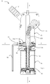
fig. 1 is a sectional view along a first plane parallel to the piston axis of a first embodiment of the actuating device according to the present invention with a partially inserted adjusting tool and the pivotable arm in its non-operative position; -
fig. 2a and 2b are an enlarged views of the adjustment means of the actuating device offigure 1 in a first and second configuration with the adjusting tool disengaged and engaged, respectively; -
fig. 3a and 3b are two sectional views respectively along a first plane parallel to the piston axis and a second plane orthogonal to the piston axis showing in detail the stopping element of the actuating device offigure 1 ; -
fig. 4 is a sectional view along a first plane parallel to the piston axis of the actuating device offigure 1 , with the non-operative position of the pivotable arm having been differently adjusted with respect to the configuration offig. 1 and the pivotable arm in the non-operative position; -
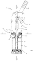
fig. 5a and 5b are side views of a second embodiment of the actuating device according to the present invention with the pivotal arm in its operative position; -
fig. 6a and 6b are side views of a third embodiment of the actuating device according to the present invention with the pivotal arm in its operative position. - In
fig. 1 an actuating device of the articulated lever or cam type for the precise positioning of a pivotable arm according to the present invention is globally indicated with 10. - The
device 10 advantageously comprises adevice body 15 and a slidingcontrol piston 11 connected to thebody 15. The slidingcontrol piston 11 is coupled to actuating means 12a,12b which slide inside thebody 15 and are connected to amechanism 13 housed inside thebody 15. Themechanism 13 induces a rotation of apivotable arm 14 about a first rotational axis B upon sliding of the piston actuating means 12a,12b along a piston axis A, wherein the first rotational axis B (seefig. 5a or6a ) is perpendicular to the piston axis A. - In the depicted non limitative example, the
mechanism 13 is an articulated lever, however the present invention is also applicable to actuatingdevices 10 comprising a cam mechanism or other types of mechanisms adapted for inducing a rotation of apivotable arm 14 upon sliding of the piston actuating means 12a,12b. - In detail, the articulated
lever mechanism 13 is a toggle lever which advantageously assures that in absence of a reversing force, the movement of the pivotable arm cannot be reversed, once the operative position corresponding to the over toggle point of the articulated lever mechanism has been reached. - The actuating means comprise a first 12a and a second 12b part displaceable with respect to one another along the piston axis A. In detail, the first part of the actuating means is a
piston rod 12a and the second part of the actuating means is afork linkage 12b. Thepiston rod 12a is coupled to thefork linkage 12b by means of a threaded coupling, so that a rotation of thepiston rod 12a determines a relative displacement of the twoparts fork linkage 12b. - The
device 10 advantageously comprises adjusting means 20 for the adjustment of the length of the actuating means 12a,12b which are accessible from a lateral side of theactuating device 10. - The adjusting means 20 comprise mechanical coupling means 21a,21b,22 which act on the
piston rod 12a in order to transform a rotary control movement imparted on the coupling means 21a,21b about a second rotary axis C transversal to the piston axis A into a relative displacement between thepiston rod 12a and thefork linkage 12b along the piston axis A. This relative displacement causes a change in the overall length of the actuating means 12a,12b and therefore in the piston stroke. Accordingly, the end-of-stroke position relating to the non-operative position of thepivotable arm 14 is modified, thereby achieving a stepless setting of the said non-operative position. - In the depicted non limitative example, the coupling means 21a,21b,22 comprise two rotary
toothed elements toothed element 22 which is coaxially constrained to thepiston rod 12a. When at least one of the two firstrotary elements rotary element 22, a rotation of the engaged firstrotary element rotary element 22 about the piston axis A. This causes a rotation of thepiston rod 12a and consequently a displacement of thefork linkage 12b so that the overall length of the piston actuating means 12a,12b is changed. - However, the present invention is also applicable to alternative mechanical coupling means like e.g. rotary elements which couple by friction or an endless screw coupled to a threaded piston rod.
- The first
rotary elements seat 23 for the insertion of an adjustingtool 50, which is better shown infigures 2a and 2b . - The first
rotary elements element 24 which in the depicted embodiment is a spherical element. Thespherical element 24 is retained into arespective hole 24a which is open at two opposite ends. A first end of the throughhole 24a opens out into theadjustment tool seat 23 and a second end of thetrough hole 24a opens out towards thedevice body 15 and particularly towards anannular seat 15a obtained in thebody 15 substantially at thetool seat 23 of the firstrotary elements - In the engaged configuration (
fig. 2b ), namely when the adjustingtool 50 is inserted into therelated seat 23 and pushes the firstrotary elements rotary element 22, the adjustingtool 50 urges thespherical element 24 into theannular seat 15a of thebody 15, thereby maintaining the firstrotary elements rotary element 22. - Furthermore, in the engaged configuration, the
spherical element 24 also interferes with the adjustingtool 50 thereby retaining theadjustment tool 50 into itsseat 23 and avoiding an accidental fall of the same 50. - The first
rotary elements rotary element elastic means 25 is a spring wound around the firstrotary elements device body 15, so that the spring is compressed when the adjustingtool 50 pushes the firstrotary element rotary element 22. - The
piston rod 12a bears at least one stoppingelement 30 which cooperates with correspondingsecond seats 31 obtained in thepiston 11 in order to substantially maintain the angular position of thepiston rod 12a against a rotation about the piston axis A. - In the depicted non limitative example, the stopping
element 30 comprises a couple of secondspherical elements 30a cooperating with secondelastic means 30b forcing the secondspherical elements 30a into the correspondingseats 31. - In the non limitative example of
figure 1 , theactuating device 10 is a clamping unit or power clamp and thepiston 11 is pneumatically actuated by means of adouble effect cylinder 16. However, the present invention is also applicable to pivoting units also known as power pivots. - In the alternative example depicted in
figures 5a and 5b , the clampingunit 10 is actuated by means of anelectrical actuator 17. - According to a further embodiment of the invention shown in
figures 6a and 6b , thesecond part 12b of the piston actuating means 12a,12b is connected to alever 18 for manually operating the articulatedlever mechanism 13.
Claims (15)
- Actuating device (10) of the articulated lever or cam type comprising a body (15) coupled to a sliding control piston (11), the piston (11) being connected to or coupled to actuating means (12a, 12b) movable along a first piston axis (A) and operatively coupled to a pivotable arm (14) through interposition of an articulated lever or a cam mechanism (13) in order to induce a pivoting movement of the pivotable arm (14) about a first rotational axis (B) perpendicular to the piston axis (A) upon a sliding movement of the actuating means (12a,12b) along the piston axis (A), the pivotable arm (14) being movable between a non-operative angular position and an operative angular position, the actuating means (12a,12b) comprising a first (12a) and a second part (12b) displaceable with respect to one another along the piston axis (A), and adjusting means (20) for the adjustment of the length of the actuating means (12a,12b), characterized in that the adjusting means (20) comprise mechanical coupling means (21a,21b,22) acting on the first part (12a) of the actuating means in order to transform a rotary control movement imparted on said coupling means (21a,21b,22) about a second rotary axis (C) transversal to the piston axis (A), into a relative displacement between the first (12a) and the second (12b) part of the piston actuating means (12a,12b) along the piston axis (A), thereby modifying the length of the actuating means (12a,12b).
- Actuating device (10) of the articulated lever or cam type according to claim 1, wherein the second rotary axis (C) is perpendicular to the piston axis (A).
- Actuating device (10) of the articulated lever or cam type according to claim 1 or 2, wherein the mechanical coupling means (21a,21b,22) comprise at least one first rotary element (21a,21b) adapted to rotate about the second rotary axis (C), which can be brought into engagement on a second rotary element (22) coaxially constrained to the first part (12a) of the actuating means (12a,12b), the rotation of the at least one first rotary element (21a,21b) about the second rotary axis (C) when engaged on the second rotary element (22) causing a rotation of the second rotary element (22) about the piston axis (A).
- Actuating device (10) of the articulated lever or cam type according to claim 3, wherein the at least one first rotary element (21a,21b) and the second rotary element (22) are toothed elements, preferably toothed crowns or cones.
- Actuating device (10) of the articulated lever or cam type according to claim 3, wherein the at least one first rotary element (21a,21b) and the second rotary element (22) are adapted to couple between each other by friction.
- Actuating device (10) of the articulated lever or cam type according to any of claims 3 to 5, wherein the at least one first rotary element (21a,21b) comprises a seat (23) for receiving an adjustment tool (50) and a blocking element (24) which cooperates with a first seat (15a) obtained in the device body (15) and with the adjustment tool seat (23) in order to hold the first rotary element (21a,21b) into an engagement position with the second rotary element (22), when the adjustment tool (50) is inserted into the adjustment tool seat (23) and to retain the adjustment tool (50) into its seat (23).
- Actuating device (10) of the articulated lever or cam type according to claim 6, wherein the blocking element is a first spherical element (24) retained into a hole (24a) obtained in the at least one first rotary element (21a,21b) which, at a first end, opens out into the adjustment tool seat (23).
- Actuating device (10) of the articulated lever or cam type according to any of claims 3 to 7, wherein the at least one first rotary element (21a,21b) is coupled to first elastic means (25) adapted to urge the at least one first rotary element (21a,21b) into its disengaged position.
- Actuating device (10) of the articulated lever or cam type according to claim 1 or 2, wherein the mechanical coupling means comprise an endless screw coupled to the first part (12a) of the actuating means (12a,12b) so that a rotation of the endless screw determines a displacement of the first part (12a) of the actuating means (12a,12b) with respect to the second part (12b) of the actuating means (12a,12b), wherein the axis of the endless screw is the second rotary axis (C).
- Actuating device (10) of the articulated lever or cam type according to any of the preceding claims, wherein the two parts (12a,12b) of the actuating means comprise a piston rod (12a) and a linking element (12b) slidably coupled to each other, the linking element (12b) being connected to the articulated lever or a cam mechanism (13).
- Actuating device (10) of the articulated lever or cam type according to claim 10, wherein the piston rod (12a) and the linking element (12b) comprise reciprocally coupled threaded surfaces and the rotary control movement imparted on said coupling means (21a,21b,22) about the second rotary axis (C) is transformed into a relative rotation between the piston rod (12a) and the linking element (12b).
- Actuating device (10) of the articulated lever or cam type according to claim 10 or 11, wherein the connecting element (12b) is a fork linkage.
- Actuating device (10) of the articulated lever or cam type according to any of claims 10 to 12, wherein the piston rod (12a) comprises at least one stopping element (30) which cooperates with a corresponding second seat (31) obtained in the piston (11) in order to substantially maintain the angular position of the piston rod (12a) against a rotation about the piston axis (A).
- Actuating device (10) of the articulated lever or cam type according to claim 13, wherein the at least one stopping element (30) comprises at least a second spherical element (30a) cooperating with second elastic means (30b) forcing the second spherical element (30a) into said corresponding seat (31) obtained in the piston (11).
- Actuating device (10) of the articulated lever or cam type according to any of the preceding claims, wherein the actuating device (10) is a power clamp or a power pivot.
Priority Applications (1)
| Application Number | Priority Date | Filing Date | Title |
|---|---|---|---|
| EP16164321.8A EP3078453B1 (en) | 2015-04-09 | 2016-04-07 | Actuating device of the articulated lever or cam type for the precise positioning of a pivotable arm |
Applications Claiming Priority (2)
| Application Number | Priority Date | Filing Date | Title |
|---|---|---|---|
| PCT/EP2015/057783 WO2016162074A1 (en) | 2015-04-09 | 2015-04-09 | Actuating device of the articulated lever or cam type for the precise positioning of a pivotable arm |
| EP16164321.8A EP3078453B1 (en) | 2015-04-09 | 2016-04-07 | Actuating device of the articulated lever or cam type for the precise positioning of a pivotable arm |
Publications (2)
| Publication Number | Publication Date |
|---|---|
| EP3078453A1 true EP3078453A1 (en) | 2016-10-12 |
| EP3078453B1 EP3078453B1 (en) | 2018-04-04 |
Family
ID=56851753
Family Applications (1)
| Application Number | Title | Priority Date | Filing Date |
|---|---|---|---|
| EP16164321.8A Active EP3078453B1 (en) | 2015-04-09 | 2016-04-07 | Actuating device of the articulated lever or cam type for the precise positioning of a pivotable arm |
Country Status (1)
| Country | Link |
|---|---|
| EP (1) | EP3078453B1 (en) |
Cited By (3)
| Publication number | Priority date | Publication date | Assignee | Title |
|---|---|---|---|---|
| IT201700091228A1 (en) * | 2017-08-07 | 2019-02-07 | Pneumax S P A | IMPLEMENTATION UNIT OF THE ARTICULATED OR CAM-LEVER TYPE OF LEVER WITH ADJUSTABLE ACCEPTANCE INTERVAL AND ADJUSTMENT METHOD OF THE ACCEPTANCE INTERVAL OF SUCH IMPLEMENTATION UNIT |
| IT202000003784A1 (en) * | 2020-02-24 | 2021-08-24 | Pneumax S P A | ACTUATION UNIT OF THE TYPE WITH ARTICULATED LEVER OR ELECTRICALLY OPERATED CAM |
| IT202000003805A1 (en) * | 2020-02-24 | 2021-08-24 | Pneumax S P A | ACTUATION UNIT OF THE TYPE WITH ARTICULATED LEVER OR ELECTRICALLY OPERATED CAM |
Citations (8)
| Publication number | Priority date | Publication date | Assignee | Title |
|---|---|---|---|---|
| US4700936A (en) | 1986-08-26 | 1987-10-20 | Lamb Technicon Corp. | Clamp mechanism |
| EP0967050A2 (en) | 1998-06-26 | 1999-12-29 | Genus Technologies | Positioning, holding or clamping device |
| DE20203790U1 (en) | 2002-03-08 | 2002-07-18 | Tuenkers Maschinenbau Gmbh | Toggle clamp |
| EP1262285A2 (en) | 2001-04-30 | 2002-12-04 | Btm Corporation | Adjustable stroke clamp |
| EP1524081A2 (en) | 2003-10-16 | 2005-04-20 | VEP Automation S.r.l. | Control unit for controlling the angular end-of-stroke positions of the clamping arm of a locking device of the articulated lever type |
| EP1849559A1 (en) * | 2006-04-27 | 2007-10-31 | UNIVER S.p.A. | Positioning and/or clamping apparatus, with adjustable opening position of the working arm |
| DE102012103092A1 (en) | 2012-04-11 | 2013-10-17 | Zf Lenksysteme Gmbh | Method for sequentially determining rotor layer angle of electromotor in electronic power steering device of motor car, involves utilizing counter voltage as control signal to adjust change of sensor power source and processing circuit |
| EP2692482A2 (en) * | 2012-08-01 | 2014-02-05 | Delaware Capital Formation, Inc. | Toggle lever clamp |
-
2016
- 2016-04-07 EP EP16164321.8A patent/EP3078453B1/en active Active
Patent Citations (8)
| Publication number | Priority date | Publication date | Assignee | Title |
|---|---|---|---|---|
| US4700936A (en) | 1986-08-26 | 1987-10-20 | Lamb Technicon Corp. | Clamp mechanism |
| EP0967050A2 (en) | 1998-06-26 | 1999-12-29 | Genus Technologies | Positioning, holding or clamping device |
| EP1262285A2 (en) | 2001-04-30 | 2002-12-04 | Btm Corporation | Adjustable stroke clamp |
| DE20203790U1 (en) | 2002-03-08 | 2002-07-18 | Tuenkers Maschinenbau Gmbh | Toggle clamp |
| EP1524081A2 (en) | 2003-10-16 | 2005-04-20 | VEP Automation S.r.l. | Control unit for controlling the angular end-of-stroke positions of the clamping arm of a locking device of the articulated lever type |
| EP1849559A1 (en) * | 2006-04-27 | 2007-10-31 | UNIVER S.p.A. | Positioning and/or clamping apparatus, with adjustable opening position of the working arm |
| DE102012103092A1 (en) | 2012-04-11 | 2013-10-17 | Zf Lenksysteme Gmbh | Method for sequentially determining rotor layer angle of electromotor in electronic power steering device of motor car, involves utilizing counter voltage as control signal to adjust change of sensor power source and processing circuit |
| EP2692482A2 (en) * | 2012-08-01 | 2014-02-05 | Delaware Capital Formation, Inc. | Toggle lever clamp |
Cited By (5)
| Publication number | Priority date | Publication date | Assignee | Title |
|---|---|---|---|---|
| IT201700091228A1 (en) * | 2017-08-07 | 2019-02-07 | Pneumax S P A | IMPLEMENTATION UNIT OF THE ARTICULATED OR CAM-LEVER TYPE OF LEVER WITH ADJUSTABLE ACCEPTANCE INTERVAL AND ADJUSTMENT METHOD OF THE ACCEPTANCE INTERVAL OF SUCH IMPLEMENTATION UNIT |
| WO2019030623A1 (en) * | 2017-08-07 | 2019-02-14 | Pneumax S.P.A. | Actuating unit of the articulated lever or cam type with adjustable acceptance interval and method for adjusting the acceptance interval of such actuating unit |
| IT202000003784A1 (en) * | 2020-02-24 | 2021-08-24 | Pneumax S P A | ACTUATION UNIT OF THE TYPE WITH ARTICULATED LEVER OR ELECTRICALLY OPERATED CAM |
| IT202000003805A1 (en) * | 2020-02-24 | 2021-08-24 | Pneumax S P A | ACTUATION UNIT OF THE TYPE WITH ARTICULATED LEVER OR ELECTRICALLY OPERATED CAM |
| WO2021171189A1 (en) * | 2020-02-24 | 2021-09-02 | Pneumax S.P.A. | Electrically operated actuating unit of the articulated lever or cam type |
Also Published As
| Publication number | Publication date |
|---|---|
| EP3078453B1 (en) | 2018-04-04 |
Similar Documents
| Publication | Publication Date | Title |
|---|---|---|
| US10174820B2 (en) | Actuating device of the articulated lever or cam type for the precise positioning of a pivotable arm | |
| EP1483084B1 (en) | Adjustable pliers wrench | |
| EP3078453B1 (en) | Actuating device of the articulated lever or cam type for the precise positioning of a pivotable arm | |
| GB2438973A (en) | Self-adjusting locking pliers | |
| US10456824B2 (en) | Safety power assist for manual press | |
| DE3638526C1 (en) | Workpiece clamping device that can be driven by an electric motor | |
| US20110001283A1 (en) | Quick release bench vise system | |
| US7290816B2 (en) | Work piece gripping device for robotized manipulating systems | |
| US4529182A (en) | Wide opening gripping jaw assembly | |
| JP3143250B2 (en) | Actuator | |
| DE102018002358B4 (en) | Toggle lever clamping device, for use in the body shop of the automotive industry with an additional abutment on the toggle joint element | |
| DE102005049647B3 (en) | Clamping system for clamping workpieces comprises clamping head with mounted clamping arm, converter and drive shaft linked to clamping arm which operates arm between clamped clearance position of workpieces and fixed contact position | |
| EP3000566B1 (en) | Gripping device | |
| EP1960160B1 (en) | Clamping device with two drive units | |
| AU677400B2 (en) | Machining tool for work pieces | |
| EP1849559A1 (en) | Positioning and/or clamping apparatus, with adjustable opening position of the working arm | |
| EP2177319B1 (en) | Device for stopping the oscillation of the arm of a handling equipment of the swingable lever type | |
| WO2009127186A1 (en) | Pneumatic hand-held strapping device | |
| CN107009160B (en) | Drive device and workpiece clamping unit equipped with the same | |
| EP3404281B1 (en) | Device for actuating a mechanical device, in particular a braking device | |
| US20060163309A1 (en) | Tool for mechanically machining workpieces | |
| US20240033890A1 (en) | Crimping and/or pinching accessory for power tool | |
| DE102004052009B3 (en) | Mechanical joining, die cutting, punching, stamping and riveting device for sheet metal components, has spring and component arranged transverse to stroke axis, and tool parts spaced at distance from each other in opening position | |
| JPH02292145A (en) | Tensioner of work-piece | |
| JP4714193B2 (en) | Rolling apparatus and rolling die position correction method |
Legal Events
| Date | Code | Title | Description |
|---|---|---|---|
| REG | Reference to a national code |
Ref country code: DE Ref legal event code: R138 Ref document number: 202016008355 Country of ref document: DE Free format text: GERMAN DOCUMENT NUMBER IS 602016002283 |
|
| PUAI | Public reference made under article 153(3) epc to a published international application that has entered the european phase |
Free format text: ORIGINAL CODE: 0009012 |
|
| AK | Designated contracting states |
Kind code of ref document: A1 Designated state(s): AL AT BE BG CH CY CZ DE DK EE ES FI FR GB GR HR HU IE IS IT LI LT LU LV MC MK MT NL NO PL PT RO RS SE SI SK SM TR |
|
| AX | Request for extension of the european patent |
Extension state: BA ME |
|
| 17P | Request for examination filed |
Effective date: 20170404 |
|
| RBV | Designated contracting states (corrected) |
Designated state(s): AL AT BE BG CH CY CZ DE DK EE ES FI FR GB GR HR HU IE IS IT LI LT LU LV MC MK MT NL NO PL PT RO RS SE SI SK SM TR |
|
| RIC1 | Information provided on ipc code assigned before grant |
Ipc: B25B 5/06 20060101ALI20171025BHEP Ipc: B25B 5/12 20060101ALI20171025BHEP Ipc: B25B 5/04 20060101AFI20171025BHEP |
|
| GRAP | Despatch of communication of intention to grant a patent |
Free format text: ORIGINAL CODE: EPIDOSNIGR1 |
|
| INTG | Intention to grant announced |
Effective date: 20171222 |
|
| GRAS | Grant fee paid |
Free format text: ORIGINAL CODE: EPIDOSNIGR3 |
|
| GRAA | (expected) grant |
Free format text: ORIGINAL CODE: 0009210 |
|
| AK | Designated contracting states |
Kind code of ref document: B1 Designated state(s): AL AT BE BG CH CY CZ DE DK EE ES FI FR GB GR HR HU IE IS IT LI LT LU LV MC MK MT NL NO PL PT RO RS SE SI SK SM TR |
|
| REG | Reference to a national code |
Ref country code: GB Ref legal event code: FG4D |
|
| REG | Reference to a national code |
Ref country code: CH Ref legal event code: EP |
|
| REG | Reference to a national code |
Ref country code: AT Ref legal event code: REF Ref document number: 985087 Country of ref document: AT Kind code of ref document: T Effective date: 20180415 |
|
| REG | Reference to a national code |
Ref country code: FR Ref legal event code: PLFP Year of fee payment: 3 |
|
| REG | Reference to a national code |
Ref country code: IE Ref legal event code: FG4D |
|
| REG | Reference to a national code |
Ref country code: DE Ref legal event code: R096 Ref document number: 602016002283 Country of ref document: DE |
|
| REG | Reference to a national code |
Ref country code: NL Ref legal event code: MP Effective date: 20180404 |
|
| REG | Reference to a national code |
Ref country code: LT Ref legal event code: MG4D |
|
| PG25 | Lapsed in a contracting state [announced via postgrant information from national office to epo] |
Ref country code: NL Free format text: LAPSE BECAUSE OF FAILURE TO SUBMIT A TRANSLATION OF THE DESCRIPTION OR TO PAY THE FEE WITHIN THE PRESCRIBED TIME-LIMIT Effective date: 20180404 |
|
| PG25 | Lapsed in a contracting state [announced via postgrant information from national office to epo] |
Ref country code: PL Free format text: LAPSE BECAUSE OF FAILURE TO SUBMIT A TRANSLATION OF THE DESCRIPTION OR TO PAY THE FEE WITHIN THE PRESCRIBED TIME-LIMIT Effective date: 20180404 Ref country code: LT Free format text: LAPSE BECAUSE OF FAILURE TO SUBMIT A TRANSLATION OF THE DESCRIPTION OR TO PAY THE FEE WITHIN THE PRESCRIBED TIME-LIMIT Effective date: 20180404 Ref country code: ES Free format text: LAPSE BECAUSE OF FAILURE TO SUBMIT A TRANSLATION OF THE DESCRIPTION OR TO PAY THE FEE WITHIN THE PRESCRIBED TIME-LIMIT Effective date: 20180404 Ref country code: FI Free format text: LAPSE BECAUSE OF FAILURE TO SUBMIT A TRANSLATION OF THE DESCRIPTION OR TO PAY THE FEE WITHIN THE PRESCRIBED TIME-LIMIT Effective date: 20180404 Ref country code: BG Free format text: LAPSE BECAUSE OF FAILURE TO SUBMIT A TRANSLATION OF THE DESCRIPTION OR TO PAY THE FEE WITHIN THE PRESCRIBED TIME-LIMIT Effective date: 20180704 Ref country code: NO Free format text: LAPSE BECAUSE OF FAILURE TO SUBMIT A TRANSLATION OF THE DESCRIPTION OR TO PAY THE FEE WITHIN THE PRESCRIBED TIME-LIMIT Effective date: 20180704 Ref country code: SE Free format text: LAPSE BECAUSE OF FAILURE TO SUBMIT A TRANSLATION OF THE DESCRIPTION OR TO PAY THE FEE WITHIN THE PRESCRIBED TIME-LIMIT Effective date: 20180404 Ref country code: AL Free format text: LAPSE BECAUSE OF FAILURE TO SUBMIT A TRANSLATION OF THE DESCRIPTION OR TO PAY THE FEE WITHIN THE PRESCRIBED TIME-LIMIT Effective date: 20180404 |
|
| PG25 | Lapsed in a contracting state [announced via postgrant information from national office to epo] |
Ref country code: LV Free format text: LAPSE BECAUSE OF FAILURE TO SUBMIT A TRANSLATION OF THE DESCRIPTION OR TO PAY THE FEE WITHIN THE PRESCRIBED TIME-LIMIT Effective date: 20180404 Ref country code: RS Free format text: LAPSE BECAUSE OF FAILURE TO SUBMIT A TRANSLATION OF THE DESCRIPTION OR TO PAY THE FEE WITHIN THE PRESCRIBED TIME-LIMIT Effective date: 20180404 Ref country code: HR Free format text: LAPSE BECAUSE OF FAILURE TO SUBMIT A TRANSLATION OF THE DESCRIPTION OR TO PAY THE FEE WITHIN THE PRESCRIBED TIME-LIMIT Effective date: 20180404 Ref country code: GR Free format text: LAPSE BECAUSE OF FAILURE TO SUBMIT A TRANSLATION OF THE DESCRIPTION OR TO PAY THE FEE WITHIN THE PRESCRIBED TIME-LIMIT Effective date: 20180705 |
|
| REG | Reference to a national code |
Ref country code: AT Ref legal event code: MK05 Ref document number: 985087 Country of ref document: AT Kind code of ref document: T Effective date: 20180404 |
|
| REG | Reference to a national code |
Ref country code: BE Ref legal event code: MM Effective date: 20180430 |
|
| PG25 | Lapsed in a contracting state [announced via postgrant information from national office to epo] |
Ref country code: PT Free format text: LAPSE BECAUSE OF FAILURE TO SUBMIT A TRANSLATION OF THE DESCRIPTION OR TO PAY THE FEE WITHIN THE PRESCRIBED TIME-LIMIT Effective date: 20180806 |
|
| REG | Reference to a national code |
Ref country code: DE Ref legal event code: R097 Ref document number: 602016002283 Country of ref document: DE |
|
| REG | Reference to a national code |
Ref country code: IE Ref legal event code: MM4A |
|
| PG25 | Lapsed in a contracting state [announced via postgrant information from national office to epo] |
Ref country code: DK Free format text: LAPSE BECAUSE OF FAILURE TO SUBMIT A TRANSLATION OF THE DESCRIPTION OR TO PAY THE FEE WITHIN THE PRESCRIBED TIME-LIMIT Effective date: 20180404 Ref country code: LU Free format text: LAPSE BECAUSE OF NON-PAYMENT OF DUE FEES Effective date: 20180407 Ref country code: MC Free format text: LAPSE BECAUSE OF FAILURE TO SUBMIT A TRANSLATION OF THE DESCRIPTION OR TO PAY THE FEE WITHIN THE PRESCRIBED TIME-LIMIT Effective date: 20180404 Ref country code: SK Free format text: LAPSE BECAUSE OF FAILURE TO SUBMIT A TRANSLATION OF THE DESCRIPTION OR TO PAY THE FEE WITHIN THE PRESCRIBED TIME-LIMIT Effective date: 20180404 Ref country code: RO Free format text: LAPSE BECAUSE OF FAILURE TO SUBMIT A TRANSLATION OF THE DESCRIPTION OR TO PAY THE FEE WITHIN THE PRESCRIBED TIME-LIMIT Effective date: 20180404 Ref country code: CZ Free format text: LAPSE BECAUSE OF FAILURE TO SUBMIT A TRANSLATION OF THE DESCRIPTION OR TO PAY THE FEE WITHIN THE PRESCRIBED TIME-LIMIT Effective date: 20180404 Ref country code: EE Free format text: LAPSE BECAUSE OF FAILURE TO SUBMIT A TRANSLATION OF THE DESCRIPTION OR TO PAY THE FEE WITHIN THE PRESCRIBED TIME-LIMIT Effective date: 20180404 Ref country code: AT Free format text: LAPSE BECAUSE OF FAILURE TO SUBMIT A TRANSLATION OF THE DESCRIPTION OR TO PAY THE FEE WITHIN THE PRESCRIBED TIME-LIMIT Effective date: 20180404 |
|
| PLBE | No opposition filed within time limit |
Free format text: ORIGINAL CODE: 0009261 |
|
| STAA | Information on the status of an ep patent application or granted ep patent |
Free format text: STATUS: NO OPPOSITION FILED WITHIN TIME LIMIT |
|
| PG25 | Lapsed in a contracting state [announced via postgrant information from national office to epo] |
Ref country code: BE Free format text: LAPSE BECAUSE OF NON-PAYMENT OF DUE FEES Effective date: 20180430 Ref country code: SM Free format text: LAPSE BECAUSE OF FAILURE TO SUBMIT A TRANSLATION OF THE DESCRIPTION OR TO PAY THE FEE WITHIN THE PRESCRIBED TIME-LIMIT Effective date: 20180404 Ref country code: IT Free format text: LAPSE BECAUSE OF FAILURE TO SUBMIT A TRANSLATION OF THE DESCRIPTION OR TO PAY THE FEE WITHIN THE PRESCRIBED TIME-LIMIT Effective date: 20180404 |
|
| 26N | No opposition filed |
Effective date: 20190107 |
|
| PG25 | Lapsed in a contracting state [announced via postgrant information from national office to epo] |
Ref country code: IE Free format text: LAPSE BECAUSE OF NON-PAYMENT OF DUE FEES Effective date: 20180407 |
|
| PG25 | Lapsed in a contracting state [announced via postgrant information from national office to epo] |
Ref country code: SI Free format text: LAPSE BECAUSE OF FAILURE TO SUBMIT A TRANSLATION OF THE DESCRIPTION OR TO PAY THE FEE WITHIN THE PRESCRIBED TIME-LIMIT Effective date: 20180404 |
|
| REG | Reference to a national code |
Ref country code: CH Ref legal event code: PL |
|
| PG25 | Lapsed in a contracting state [announced via postgrant information from national office to epo] |
Ref country code: MT Free format text: LAPSE BECAUSE OF NON-PAYMENT OF DUE FEES Effective date: 20180407 Ref country code: CH Free format text: LAPSE BECAUSE OF NON-PAYMENT OF DUE FEES Effective date: 20190430 Ref country code: LI Free format text: LAPSE BECAUSE OF NON-PAYMENT OF DUE FEES Effective date: 20190430 |
|
| PG25 | Lapsed in a contracting state [announced via postgrant information from national office to epo] |
Ref country code: TR Free format text: LAPSE BECAUSE OF FAILURE TO SUBMIT A TRANSLATION OF THE DESCRIPTION OR TO PAY THE FEE WITHIN THE PRESCRIBED TIME-LIMIT Effective date: 20180404 |
|
| PG25 | Lapsed in a contracting state [announced via postgrant information from national office to epo] |
Ref country code: HU Free format text: LAPSE BECAUSE OF FAILURE TO SUBMIT A TRANSLATION OF THE DESCRIPTION OR TO PAY THE FEE WITHIN THE PRESCRIBED TIME-LIMIT; INVALID AB INITIO Effective date: 20160407 Ref country code: CY Free format text: LAPSE BECAUSE OF FAILURE TO SUBMIT A TRANSLATION OF THE DESCRIPTION OR TO PAY THE FEE WITHIN THE PRESCRIBED TIME-LIMIT Effective date: 20180404 Ref country code: MK Free format text: LAPSE BECAUSE OF NON-PAYMENT OF DUE FEES Effective date: 20180404 |
|
| PG25 | Lapsed in a contracting state [announced via postgrant information from national office to epo] |
Ref country code: IS Free format text: LAPSE BECAUSE OF FAILURE TO SUBMIT A TRANSLATION OF THE DESCRIPTION OR TO PAY THE FEE WITHIN THE PRESCRIBED TIME-LIMIT Effective date: 20180804 |
|
| GBPC | Gb: european patent ceased through non-payment of renewal fee |
Effective date: 20200407 |
|
| PG25 | Lapsed in a contracting state [announced via postgrant information from national office to epo] |
Ref country code: GB Free format text: LAPSE BECAUSE OF NON-PAYMENT OF DUE FEES Effective date: 20200407 |
|
| P01 | Opt-out of the competence of the unified patent court (upc) registered |
Effective date: 20230329 |
|
| PGFP | Annual fee paid to national office [announced via postgrant information from national office to epo] |
Ref country code: FR Payment date: 20230425 Year of fee payment: 8 Ref country code: DE Payment date: 20230426 Year of fee payment: 8 |