EP3078441B1 - Solder supply device - Google Patents
Solder supply device Download PDFInfo
- Publication number
- EP3078441B1 EP3078441B1 EP13898551.0A EP13898551A EP3078441B1 EP 3078441 B1 EP3078441 B1 EP 3078441B1 EP 13898551 A EP13898551 A EP 13898551A EP 3078441 B1 EP3078441 B1 EP 3078441B1
- Authority
- EP
- European Patent Office
- Prior art keywords
- solder
- supply device
- nozzle
- outer tube
- container
- Prior art date
- Legal status (The legal status is an assumption and is not a legal conclusion. Google has not performed a legal analysis and makes no representation as to the accuracy of the status listed.)
- Active
Links
- 229910000679 solder Inorganic materials 0.000 title claims description 469
- 230000007246 mechanism Effects 0.000 claims description 15
- 239000007788 liquid Substances 0.000 claims description 7
- 230000000694 effects Effects 0.000 description 5
- 239000002184 metal Substances 0.000 description 5
- 230000005484 gravity Effects 0.000 description 4
- 239000000463 material Substances 0.000 description 3
- 238000004140 cleaning Methods 0.000 description 2
- 238000000034 method Methods 0.000 description 2
- 238000010276 construction Methods 0.000 description 1
- 230000001419 dependent effect Effects 0.000 description 1
- 238000010586 diagram Methods 0.000 description 1
Images


Classifications
-
- H—ELECTRICITY
- H05—ELECTRIC TECHNIQUES NOT OTHERWISE PROVIDED FOR
- H05K—PRINTED CIRCUITS; CASINGS OR CONSTRUCTIONAL DETAILS OF ELECTRIC APPARATUS; MANUFACTURE OF ASSEMBLAGES OF ELECTRICAL COMPONENTS
- H05K3/00—Apparatus or processes for manufacturing printed circuits
- H05K3/30—Assembling printed circuits with electric components, e.g. with resistor
- H05K3/32—Assembling printed circuits with electric components, e.g. with resistor electrically connecting electric components or wires to printed circuits
- H05K3/34—Assembling printed circuits with electric components, e.g. with resistor electrically connecting electric components or wires to printed circuits by soldering
- H05K3/3457—Solder materials or compositions; Methods of application thereof
- H05K3/3468—Applying molten solder
-
- B—PERFORMING OPERATIONS; TRANSPORTING
- B05—SPRAYING OR ATOMISING IN GENERAL; APPLYING FLUENT MATERIALS TO SURFACES, IN GENERAL
- B05C—APPARATUS FOR APPLYING FLUENT MATERIALS TO SURFACES, IN GENERAL
- B05C11/00—Component parts, details or accessories not specifically provided for in groups B05C1/00 - B05C9/00
- B05C11/10—Storage, supply or control of liquid or other fluent material; Recovery of excess liquid or other fluent material
- B05C11/1002—Means for controlling supply, i.e. flow or pressure, of liquid or other fluent material to the applying apparatus, e.g. valves
-
- B—PERFORMING OPERATIONS; TRANSPORTING
- B05—SPRAYING OR ATOMISING IN GENERAL; APPLYING FLUENT MATERIALS TO SURFACES, IN GENERAL
- B05C—APPARATUS FOR APPLYING FLUENT MATERIALS TO SURFACES, IN GENERAL
- B05C17/00—Hand tools or apparatus using hand held tools, for applying liquids or other fluent materials to, for spreading applied liquids or other fluent materials on, or for partially removing applied liquids or other fluent materials from, surfaces
- B05C17/005—Hand tools or apparatus using hand held tools, for applying liquids or other fluent materials to, for spreading applied liquids or other fluent materials on, or for partially removing applied liquids or other fluent materials from, surfaces for discharging material from a reservoir or container located in or on the hand tool through an outlet orifice by pressure without using surface contacting members like pads or brushes
- B05C17/00523—Hand tools or apparatus using hand held tools, for applying liquids or other fluent materials to, for spreading applied liquids or other fluent materials on, or for partially removing applied liquids or other fluent materials from, surfaces for discharging material from a reservoir or container located in or on the hand tool through an outlet orifice by pressure without using surface contacting members like pads or brushes provided with means to heat the material
- B05C17/00526—Hand tools or apparatus using hand held tools, for applying liquids or other fluent materials to, for spreading applied liquids or other fluent materials on, or for partially removing applied liquids or other fluent materials from, surfaces for discharging material from a reservoir or container located in or on the hand tool through an outlet orifice by pressure without using surface contacting members like pads or brushes provided with means to heat the material the material being supplied to the apparatus in a solid state, e.g. rod, and melted before application
- B05C17/0053—Hand tools or apparatus using hand held tools, for applying liquids or other fluent materials to, for spreading applied liquids or other fluent materials on, or for partially removing applied liquids or other fluent materials from, surfaces for discharging material from a reservoir or container located in or on the hand tool through an outlet orifice by pressure without using surface contacting members like pads or brushes provided with means to heat the material the material being supplied to the apparatus in a solid state, e.g. rod, and melted before application the driving means for the material being manual, mechanical or electrical
- B05C17/00533—Hand tools or apparatus using hand held tools, for applying liquids or other fluent materials to, for spreading applied liquids or other fluent materials on, or for partially removing applied liquids or other fluent materials from, surfaces for discharging material from a reservoir or container located in or on the hand tool through an outlet orifice by pressure without using surface contacting members like pads or brushes provided with means to heat the material the material being supplied to the apparatus in a solid state, e.g. rod, and melted before application the driving means for the material being manual, mechanical or electrical comprising a piston
-
- B—PERFORMING OPERATIONS; TRANSPORTING
- B23—MACHINE TOOLS; METAL-WORKING NOT OTHERWISE PROVIDED FOR
- B23K—SOLDERING OR UNSOLDERING; WELDING; CLADDING OR PLATING BY SOLDERING OR WELDING; CUTTING BY APPLYING HEAT LOCALLY, e.g. FLAME CUTTING; WORKING BY LASER BEAM
- B23K3/00—Tools, devices, or special appurtenances for soldering, e.g. brazing, or unsoldering, not specially adapted for particular methods
- B23K3/06—Solder feeding devices; Solder melting pans
- B23K3/0607—Solder feeding devices
- B23K3/0638—Solder feeding devices for viscous material feeding, e.g. solder paste feeding
-
- B—PERFORMING OPERATIONS; TRANSPORTING
- B41—PRINTING; LINING MACHINES; TYPEWRITERS; STAMPS
- B41F—PRINTING MACHINES OR PRESSES
- B41F15/00—Screen printers
- B41F15/14—Details
- B41F15/40—Inking units
-
- B—PERFORMING OPERATIONS; TRANSPORTING
- B41—PRINTING; LINING MACHINES; TYPEWRITERS; STAMPS
- B41F—PRINTING MACHINES OR PRESSES
- B41F15/00—Screen printers
- B41F15/14—Details
- B41F15/40—Inking units
- B41F15/405—Spraying apparatus
-
- B—PERFORMING OPERATIONS; TRANSPORTING
- B41—PRINTING; LINING MACHINES; TYPEWRITERS; STAMPS
- B41F—PRINTING MACHINES OR PRESSES
- B41F15/00—Screen printers
- B41F15/14—Details
- B41F15/40—Inking units
- B41F15/42—Inking units comprising squeegees or doctors
-
- B—PERFORMING OPERATIONS; TRANSPORTING
- B41—PRINTING; LINING MACHINES; TYPEWRITERS; STAMPS
- B41F—PRINTING MACHINES OR PRESSES
- B41F15/00—Screen printers
- B41F15/14—Details
- B41F15/40—Inking units
- B41F15/42—Inking units comprising squeegees or doctors
- B41F15/423—Driving means for reciprocating squeegees
-
- H—ELECTRICITY
- H05—ELECTRIC TECHNIQUES NOT OTHERWISE PROVIDED FOR
- H05K—PRINTED CIRCUITS; CASINGS OR CONSTRUCTIONAL DETAILS OF ELECTRIC APPARATUS; MANUFACTURE OF ASSEMBLAGES OF ELECTRICAL COMPONENTS
- H05K3/00—Apparatus or processes for manufacturing printed circuits
- H05K3/10—Apparatus or processes for manufacturing printed circuits in which conductive material is applied to the insulating support in such a manner as to form the desired conductive pattern
- H05K3/12—Apparatus or processes for manufacturing printed circuits in which conductive material is applied to the insulating support in such a manner as to form the desired conductive pattern using thick film techniques, e.g. printing techniques to apply the conductive material or similar techniques for applying conductive paste or ink patterns
- H05K3/1216—Apparatus or processes for manufacturing printed circuits in which conductive material is applied to the insulating support in such a manner as to form the desired conductive pattern using thick film techniques, e.g. printing techniques to apply the conductive material or similar techniques for applying conductive paste or ink patterns by screen printing or stencil printing
- H05K3/1233—Methods or means for supplying the conductive material and for forcing it through the screen or stencil
-
- B—PERFORMING OPERATIONS; TRANSPORTING
- B23—MACHINE TOOLS; METAL-WORKING NOT OTHERWISE PROVIDED FOR
- B23K—SOLDERING OR UNSOLDERING; WELDING; CLADDING OR PLATING BY SOLDERING OR WELDING; CUTTING BY APPLYING HEAT LOCALLY, e.g. FLAME CUTTING; WORKING BY LASER BEAM
- B23K2101/00—Articles made by soldering, welding or cutting
- B23K2101/36—Electric or electronic devices
- B23K2101/42—Printed circuits
Definitions
- the present invention relates to a solder supply device for supplying liquid solder from a solder container housing liquid solder, the solder container being tubular and open at one end.
- Patent literature 1 listed below there are solder supply devices that supply liquid solder from a solder container by increasing the pressure inside the solder container using an air cylinder. Also, as disclosed in patent literature 2, there are devices that supply liquid solder from a solder container by operating a mechanism that increases the pressure inside the solder container using an electromagnetic motor. Patent literature 1 and 3 respectively disclose a solder supply device according to the preamble of claim 1.
- solder supply devices According to the solder supply devices disclosed in the above patent literature, it is possible to supply liquid solder from a solder container.
- an air cylinder or an electromagnetic motor must be provided, making the construction of the solder supply device complex. Also, space is required for the air cylinder or the electromagnetic motor making the solder supply device larger.
- the present invention takes account of such problems and an object thereof is to provide a solder supply device that supplies liquid solder from a solder container without using an air cylinder or an electromagnetic motor.
- solder supply device According to the above problems, a solder supply device according to claim 1 is provided.
- the nozzle for ejecting solder in the solder container to the outside of the device is inserted into the solder container.
- a piston is provided on an outer circumferential section of the nozzle and that piston is engaged inside the solder container from the opening of the solder container.
- a demarcating member is provided on the solder supply device, such that an air chamber is demarcated by the demarcating member and one out of the surface of the other end of the solder container, an adapter attached to the surface of the other end, and a surface of the piston facing the opening of the solder container.
- solder is supplied from the tip of the nozzle by relatively moving the solder container and the piston by air being supplied to the air chamber.
- solder can be supplied from a solder container without requiring an air cylinder or an electromagnetic motor.
- the piston is relatively movable to the nozzle.
- a lid that seals the opening of the solder container in a state with the tip of the nozzle inserted functions as a demarcating member.
- the piston is fixedly provided on the outer circumferential section of the nozzle.
- an outer tube with an opening at one end and that stores the solder container in a state with the other end of the solder container engaged from the opening functions as a demarcating member.
- an inner tube with an opening at both ends is provided.
- This inner tube holds the piston or the nozzle at one end, extends from the opening of the solder container at the other end, and is fixed to the outer tube. By this the piston or the nozzle is fixedly held, and the solder container is able to be moved appropriately towards the piston.
- the inner tube is separable from the piston or nozzle. That is, the piston or the nozzle, which directly contact solder, are able to be removed from the inner tube. This means that it is easy to wash the piston and nozzle, which easily become dirty, individually.
- the surface opposite to the opening of the outer tube is openable/closable.
- the outer tube is swingably attached to a solder printer. That is, the solder supply device provided at a specified location on a solder printer is able to be inclined. By this, for example, by opening the surface of the outer tube opposite to the opening, and making the opened location face down, the solder container in the outer tube is ejected from the outer tube by gravity. Thus, according to the solder supply device disclosed in claim 7, it is easy to remove the solder container from the outer tube.
- the friction arising between the outer circumferential section of the piston and the inner circumferential surface of the solder container is greater than the holding force of the piston or the nozzle by the inner tube.
- the solder supply device disclosed in claim 9 is detachably mounted on a solder printer by a lock mechanism.
- the solder supply device is able to be removed from the solder printer simply by releasing the lock mechanism, facilitating the performing of exchange work and so on of the solder container outside the printer. This curtails the inside of the printer becoming dirty due to fallen solder and so on during solder container exchange.
- the exchange work is performed outside the solder printer, not in the narrow space inside the solder printer, thus making exchange work easy to perform.
- Fig. 1 shows solder printer 10 as an embodiment of the invention.
- Solder printer 10 is a device that prints solder paste onto a circuit board.
- Solder printer 10 is provided with conveyance device 20, moving device 22, squeegee device 24, and solder supply device 26.
- Conveyance device 20 has a pair of conveyor belts 30 that extend in the X-axis direction, and electromagnetic motor (refer to fig. 4 ) 32 that rotates conveyor belts 30.
- the pair of conveyor belts 30 support circuit board 34 and circuit board 34 is conveyed in the X-axis direction by the driving of electromagnetic motor 32.
- conveyance device 20 has holding device (refer to fig. 4 ) 36. Holding device 36 fixedly holds circuit board 34 supported by conveyor belts 30 in a predetermined position (the position at which circuit board 34 is shown in fig. 1 ). Note that a metal mask (not shown) is loaded on the upper surface of circuit board 34.
- Moving device 22 is configured from Y-axis direction slide mechanism 50 and X-axis direction slide mechanism 52.
- Y-axis direction slide mechanism 50 has Y-axis slider 56 provided on base 54 so as to be movable in the Y-axis direction.
- Y-axis slider 56 is moved to any position in the Y-axis direction by the driving of electromagnetic motor (refer to fig. 4 ) 58.
- X-axis direction slide mechanism 52 has X-axis slider 60 provided on a side surface of Y-axis slider 56 to be movable in the X-axis direction.
- X-axis slider 60 is moved to any position in the X-axis direction by the driving of electromagnetic motor (refer to fig. 4 ) 62.
- Squeegee device 24 is attached to Y-axis slider 56 about conveyance device 20, and moves to any position above circuit board 34 that is held by conveyance device 20.
- Squeegee device 24 has a squeegee (not shown) and the squeegee is held extending downwards by squeegee device 24 to be movable in the Y-axis direction and the up/down directions. Further, the squeegee is moved in the Y-axis direction by the driving of electromagnetic motor (refer to fig. 4 ) 66, and is moved up/down by the driving of electromagnetic motor (refer to fig. 4 ) 68.
- Solder supply device 26 is attached to X-axis slider 60 and is moved to any position above base 54 by moving device 22. As shown in fig. 2 , solder supply device 26 has solder cup 70, outer tube 72, supply nozzle 74, inner tube 76, and fixed lid 78. Solder cup 70 is a bottomed cylindrical container with an opening at one end; solder cup 70 is filled with solder paste. Flange section 80 is formed on the outer circumferential surface at the opening side of solder cup 70; a screw thread (not shown) is formed between flange 80 and the edge of the opening side. Solder cup 70 is sold commercially with a lid (not shown) that engages with the screw thread covering the opening. That is, solder paste manufacturers sell solder cups 70 after filling solder cups 70 with solder paste and covering the opening with a lid. Users purchase solder cups 70 and use them with the lid removed.
- outer tube 72 is a bottomed cylinder with an opening at one end; solder cup 70 is stored inside outer tube 72.
- the inner circumferential surface of outer tube 72 is configured from first inner circumferential surface 82 that is positioned at the opening side of outer tube 72, and second inner circumferential surface 84 that is positioned at bottom surface 83 of outer tube 72.
- the inside diameter of first inner circumferential surface 82 is slightly larger than the outer diameter of flange section 80 of solder cup 70; the inside diameter of second inner circumferential surface 84 is slightly larger than the outer diameter of the tubular section of solder cup 70.
- the end of the bottom side of solder cup 70 is engaged from the opening of outer tube 72 such that solder cup 70 is stored in outer tube 72.
- solder cup 70 is slidable inside outer tube 72.
- the depth dimension of a portion of second inner circumferential surface 84 of outer tube 72 is longer than the length dimension from flange section 80 of solder cup 70 to the bottom surface, and flange section 80 of solder cup 70 stored in outer tube 72 contacts the step surface between first inner circumferential surface 82 and second inner circumferential surface 84 of outer tube 72. Therefore, space 86 is formed between the bottom surface of solder cup 70 and bottom surface 83 of outer tube 72.
- the bottom surface refers to the surface on the opposite side to the opening of a bottomed cylindrical member. In other words, even if the surface on the opposite side to the opening of a bottomed cylindrical member is positioned towards the top, and the opening is positioned towards the bottom, the surface on the opposite side to the opening is given as the bottom surface, not the lid.
- supply nozzle 74 is configured from nozzle section 88 and flange section 90; nozzle section 88 and flange section 90 are formed as one body from material that is elastically deformable.
- Nozzle section 88 is substantially cylindrical with nozzle hole 92 formed running through the inside.
- Flange section 90 extends in a disk shape from the outer circumferential surface of an end of the nozzle section; the outer diameter of flange section 90 is slightly larger than the inside diameter of solder cup 70.
- flange section 90 is engaged inside solder cup 70 such that nozzle section 88 faces the opening side of solder cup 70; supply nozzle 74 slides inside solder cup 70 with the outer circumferential section of flange section 90 elastically deformed.
- inner tube 76 has cylindrical tube section 96, and ring section 98 that covers the edge of tube section 96; supply nozzle 74 is held by ring section 98.
- the outer circumferential surface of nozzle section 88 of supply nozzle 74 is configured from first outer surface 100 positioned on the flange section 90 side and second outer circumferential surface 102 positioned at the tip side of nozzle section 88; the outer diameter of first outer diameter surface 100 is smaller than the outer diameter of second outer circumferential surface 102.
- the inside diameter of ring section 98 of inner tube 76 is slightly larger than the outer diameter of first outer circumferential surface 100 and slightly smaller than the outer diameter of second outer circumferential surface 102.
- nozzle section 88 engages with the inside diameter section of ring section 98 while a portion of second circumferential surface 102 is elastically deformed, and the inside diameter of ring section 98 and outer circumferential surface 100 of nozzle section 88 engage.
- inner tube 76 holds supply nozzle 74 using ring section 98.
- inner tube 76 holds supply nozzle 74 using ring section 98, therefore inner tube 76 is positioned inside solder cup 70; however, the end of the side not positioned at ring section 98 of tube section 96 extends from the opening of solder cup 70.
- fixed lid 78 has ring section 106, and erected section 108 established around the entire circumference at the outer edge of ring section 106.
- a screw thread (not shown) is formed on the inner circumferential surface of erected section 108, the screw thread being engaged with the screw thread (not shown) formed at the opening end side of outer tube 72.
- fixed lid 78 is removably attached to the opening of outer tube 72.
- the inside diameter of ring section 106 is substantially the same as the inside diameter of tube section 96 of inner tube 76, and the end section that extends from solder cup 70 of tube section 96 is fixed to the inside edge of ring section 106.
- inner tube 76 is also removed from inside outer tube 72.
- supply nozzle 74 held by inner tube 76 is also removed from inside outer tube 72.
- solder cup 70 is also removed from outer tube 72 by the friction arising between flange section 90 of supply nozzle 74 and the inner circumferential surface of solder cup 70. That is, by removing fixed lid 78 from outer tube 72, inner tube 76, supply nozzle 74, and solder cup 70 are removed as one from outer tube 72.
- through-hole 110 is formed in bottom surface 83 of outer tube 72, and air adapter 112 is attached in through-hole 110.
- Air adapter 112 is connected to an end of air tube 114, and the other end of air tube 114 is connected to device-side air coupler 116.
- slider-side air coupler (refer to fig. 3 ) 118 provided at the arrangement position of solder supply device 26 to device-side air coupler 116, air is supplied to space 86 inside outer tube 72, and solder paste is ejected from nozzle hole 92 of supply nozzle 74.
- an end of air tube 120 is connected to slider-side air coupler 118, and the other end of air tube 120 is connected to air supply device (refer to fig. 4 ) 122.
- air supply device 122 By this, air is supplied from air supply device 122 to space 86 inside outer tube 72.
- space 86 the bottom surface of solder cup 70 is pressed towards supply nozzle 74 and solder cup 70 moves down. In this case, the solder paste filling solder cup 70 is compressed and is ejected from nozzle hole 92 of supply nozzle 74.
- solder supply device 26 supplies solder paste.
- space 86 is demarcated by the bottom surface of solder cup 70 and bottom surface 83 of outer tube 72, with space 86 functioning as an air chamber. That is, by the bottom surface of solder cup 70 being directly pressed by air, solder paste inside solder cup 70 is ejected from nozzle hole 92.
- solder supply device 26 it is not necessary to provide a cylinder device for pushing solder cup 70, and solder supply device 26 can be made more compact. Also, because there is no need to provide a cylinder device, costs are reduced. Further, because there is no need to provide a cylinder device, the configuration of solder supply device 26 can be made simple.
- solder supply device 26 is detachably mounted on X-axis slider 60 by clip lock 130.
- bracket 132 is attached to the lower end of X-axis slider 60, and the lower surface of solder supply device 26 is supported by bracket 132.
- solder supply device 26 is able to be loaded on bracket 132.
- a through-hole approximately the same as the inner diameter of ring section 106 of fixed lid 78 of solder supply device 26 is formed in bracket 132.
- Two surrounding plates 134 and 136 are fixed on X-axis slider 60 above bracket 132 facing each other and perpendicular to bracket 132.
- the distance between the two surrounding brackets 134 and 136 is slightly longer than the outer diameter of outer tube 72 of solder supply device 26, and solder supply device 26 is loaded between the two surrounding plates 134 and 136.
- an end of opening/closing plate 140 is attached to surrounding plate 134 via hinge 138.
- Lever section 146 of clip lock 130 is provided on the other end of opening/closing plate 140, and hook stopper 148 of clip lock 130 is provided on surrounding plate 136.
- solder supply device 26 is fixedly mounted on X-axis slider 60. Also, by releasing the locking of clip lock 130 and opening opening/closing plate 140, solder supply device 26 is able to be removed from X-axis slider 60. Note that, device-side air coupler 116 and slider-side air coupler 118 are detachable, and device-side air coupler 116 is removed from slider-side air coupler 118 when solder supply device 26 is removed from X-axis slider 60.
- solder printer 10 is provided with control device 150.
- Control device 150 is provided with controller 152 and multiple drive circuits 154. Multiple drive circuits 154 are connected to the above-mentioned electromagnetic motors 32, 58, 62, 66, and 68, holding device 36, and air supply device 122.
- controller 152 is provided with a CPU, ROM or RAM, forming the main parts of a computer, and is connected to the multiple drive circuits 154.
- the operation of conveyance device 20, moving device 22, squeegee device 24, and solder supply device 26 is controlled by controller 152.
- solder paste is supplied onto the upper surface of a metal mask loaded on circuit board 34 by solder supply device 26, and that solder paste is applied by squeegee device 24. Pattern holes matching the pattern of the pads and so on of circuit board 34 are formed in the metal mask, and solder paste is printed onto circuit board 34 via the pattern holes.
- circuit board 34 is conveyed to a work position, and fixedly held at that position by holding device 36.
- solder supply device 26 based on commands of controller 152, moves to a prescribed position above circuit board 34.
- solder supply device 26 supplies air from air supply device 122 into space 86 inside outer tube 72.
- solder paste is ejected from nozzle hole 92, thus supplying solder paste onto the upper surface of the metal mask loaded on circuit board 34.
- squeegee device 24 is moved above the location where solder paste was supplied.
- solder printer 10 prints solder paste onto circuit board 34.
- solder cup 70 When printing solder paste onto circuit board 34 as described above, because solder paste is supplied from solder cup 70 of solder supply device 26, solder cup 70 empties. Thus, a solder cup 70 which has become empty must be exchanged for a solder cup 70 which is full of solder paste. The exchange procedure for solder cup 70 is described below.
- solder supply device 26 is removed from X-axis slider 60 and removed from solder printer 10.
- fixed lid 78 is rotated counterclockwise with respect to outer tube 72 to release the engagement of fixed lid 78 and outer tube 72.
- solder cup 70 and fixed lid 78 is pulled away from the other.
- fixed lid 78, inner tube 76, and supply nozzle 74 are separated as one from solder cup 70. That is, supply nozzle 74 is removed from the inside of empty solder cup 70 along with inner tube 76.
- a new solder cup 70 that is a solder cup 70 full of solder paste, is set inside outer tube 72. Then, with supply nozzle 74 engaged inside that solder cup 70, fixed lid 78 is engaged with the opening of outer tube 72. By this, as shown in fig. 8 , new solder cup 70 is set inside solder supply device 26.
- solder supply device 26 When new solder cup 70 is set in solder supply device 26, solder supply device 26 is drawn into solder printer 10 and loaded on bracket 132. Then opening/closing plate 140 is closed and clip lock 130 is locked. Also, device-side air coupler 116 is attached to slider-side air coupler 118. By this, solder supply device 26 is fixedly attached to X-axis slider 60, thereby completing exchange of solder cup 70.
- solder printer 10 by the engaging of fixed lid 78 and outer tube 72, fixed lid 78, outer tube 72, inner tube 76, supply nozzle 74, and solder cup 70 are integrated as one, thus an operator is able to hold solder supply device 26 with one hand and easily remove it from solder printer 10.
- solder printer 10 it is possible to perform exchange of solder cup 70 outside of solder printer 10, which makes it possible to curtail getting the inside of solder printer 10 dirty due to fallen solder paste and so on during exchange.
- the exchange work is performed outside solder printer 10, not in the narrow space inside solder printer 10, thus making exchange work easy to perform.
- cleaning of solder cup 70 and so on can also be performed outside solder printer 10, so cleaning work is also easy.
- supply nozzle 74 is able to be removed from inner tube 76, so supply nozzle 74, which is easily dirtied, is able to be cleaned individually.
- solder supply device 26 by preparing another solder supply device 26, it is possible to perform exchange of solder cups in an extremely short time.
- a solder supply device different to solder supply device 26 attached to X-axis slider 60 is prepared, and, as shown in fig. 8 , a new solder cup 70 is set in that different solder supply device.
- exchange of solder cups is completed by removing solder supply device 26 from X-axis slider 60 and attaching the different solder supply device set with the new solder cup 70 to X-axis slider 60.
- solder supply device 26 that is removable from X-axis slider 60 is used, but a solder supply device for which the attaching/removing of a solder cup is easy may be used.
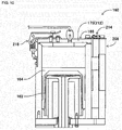
- fig. 9 shows solder supply device 160 for which the attaching/removing of a solder cup is easy.
- Solder supply device 160 has solder cup 162, adapter 164, outer tube 166, supply nozzle 168, inner tube 170, and fixed lid 172.
- Solder cup 162 has the same form as solder cup 70 of the first embodiment That is, solder cup 162 is a bottomed cylindrical container with an opening at one end and with flange section 174 formed on the outer circumferential surface at the opening side. Solder cup 162 is filled with solder paste.
- Adapter 164 is also a bottomed cylinder with an opening at one end, and solder cup 162 is stored inside adapter 164.
- the inside diameter of adapter 164 is slightly smaller than the outer diameter of flange section 174 of solder cup 162, and slightly larger than the outer diameter of the tubular section of solder cup 162.
- the end of the bottom side of solder cup 162 is engaged from the opening of adapter 164 such that solder cup 162 is stored in adapter 164.
- the depth dimension of adapter 164 is longer than the length dimension from flange section 174 of solder cup 162 to the bottom, and flange section 174 of solder cup 162 stored in adapter 164 contacts the opening end of adapter 164.
- the section of solder cup 162 further to the side of the opening than flange section 174 extends from the opening of adapter 164.
- outer tube 166 is a bottomed cylinder with an opening at one end; adapter 164 is stored inside outer tube 166.
- the inside diameter of outer tube 166 is slightly larger than the outer diameter of adapter 164.
- the bottom surface of adapter 164 and bottom surface 175 of outer tube 166 are facing each other and engaged such that adapter 164 is stored in outer tube 166.
- adapter 164 is slidable inside outer tube 166.
- recess 176 is formed in a center section on the inside of bottom surface 175 of outer tube 166; space 177 is demarcated by recess 176 and the bottom surface of adapter 164.
- supply nozzle 168 is configured from nozzle section 178 and flange section 180; nozzle section 178 and flange section 180 are formed as one body from material that is elastically deformable.
- Nozzle section 178 is substantially cylindrical with nozzle hole 182 formed running through the inside.
- Flange section 180 extends in a disk shape from the outer circumferential surface of an end of nozzle section 178; the outer diameter of flange section 180 is slightly larger than the inside diameter of solder cup 162.
- flange section 180 is engaged inside solder cup 162 such that nozzle section 178 faces the opening side of solder cup 162; supply nozzle 168 slides inside solder cup 162 with the outer circumferential section of flange section 180 elastically deformed.
- the length dimension of nozzle section 178 is longer than the depth dimension of solder cup 162.
- supply nozzle 168 and solder cup 162 move relative to each other, and, as shown in fig. 10 , even when flange section 180 is close to the bottom surface of solder cup 162, the tip of nozzle section 178 extends from the opening of solder cup 162.
- inner tube 170 has cylindrical tube section 186 and ring section 188 that covers the edge of tube section 186.
- the inside diameter of ring section 188 is slightly larger than the outer diameter of nozzle section 178 of supply nozzle 168.
- nozzle section 178 is inserted in the inside diameter section of ring section 188, and inner tube 170 supports supply nozzle 168 with flange section 180 of supply nozzle 168 contacting ring section 188.
- the length dimension of nozzle section 178 is longer than the length of inner tube 170.
- fixed lid 172 is disk-shaped, with through-hole 190 formed in a center section. Fixed lid 172 is fixed to the opening end of outer tube 166, and covers the opening of outer tube 166. Also, inside of outer tube 166, inner tube 170 is fixed to fixed lid 172 at the end opposite to ring section 188, and the tip of nozzle section 178 of supply nozzle 168 supported by inner tube 170 is inserted inside through-hole 190. Note that, the inside diameter of through-hole 190 is larger than the outer diameter of nozzle section 178.
- through-hole 200 is formed in recess 176 of bottom surface 175 of outer tube 166, and air adapter 202 is attached in through-hole 200.
- Air adapter 202 is connected to an end of air tube 204, and the other end of air tube 204 is connected to air supply device (refer to fig. 4 ) 122.
- air supply device 160 by supplying air from air supply device 122 to the inside of outer tube 166, solder paste is ejected from nozzle hole 182 of supply nozzle 168.
- air is supplied from air supply device 122, via air tube 204 and air adapter 202, to space 177 inside outer tube 166.
- air is supplied to space 177, the bottom surface of adapter 164 is pressed towards supply nozzle 168 and adapter 164 moves down.
- solder cup 162 also moves down with adapter 164 such that the solder paste in solder cup 162 is compressed. By this, solder paste is ejected from nozzle hole 182 of supply nozzle 168.
- solder supply device 160 space 177 is divided by the bottom surface of adapter 164 that houses solder cup 162 and recess 176 of outer tube 166, with space 177 functioning as an air chamber. That is, by the bottom surface of adapter that houses solder cup 162 being directly pressed by air, solder paste inside solder cup 162 is ejected from nozzle hole 182.
- solder supply device 160 in a similar manner to solder supply device 26 of the first embodiment, it is not necessary to provide a cylinder device for pushing solder cup 162, and the same effects as solder supply device 26 of the first embodiment are achieved.
- bottom surface 175 of outer tube 166 is capable of opening/closing, such that outer tube 166 is capable of swinging.
- solder cup 162 can be easily removed/inserted from/into bottom surface 175.
- outer tube 166 is held by holding unit 208; holding unit 208 is detachably mounted on X-axis slider 60.
- outer tube 166 is configured from two members - cylindrical member 210 and bottom member 212 - and bottom member 212 is attached to the top end of holding unit 208 via hinge 214. By this, bottom member 212 opens/closes, such that the top side of cylindrical member 210 is opened or closed.
- lever section 218 and joint 220 of clipping lock 216 are formed on bottom member 212, and hook stopper 222 of clip lock 216 is provided on the upper end of cylindrical member 210. Further, with bottom member 212 closed, joint 220 hooks onto hook stopper 222, and clip lock 216 is locked by the operation of lever section 218. By this, bottom member 212 adheres to the upper end of cylindrical member 210 and space 177 is sealed closed. Also, by releasing the lock of clip lock 216 by the operation of lever section 218, bottom member 212 is opened, and the upper end of cylindrical member 210 is opened too.
- outer tube 166 is swingably held by holding unit 208.
- outer tube 166 swings, as shown in fig. 11 .
- outer tube 166 is titled 90 degrees or more, and the upper end of outer tube 166 faces down.
- adapter 164 housed inside outer tube 166 is ejected from the upper end of outer tube 166 by gravity.
- solder cup 162 housed inside adapter 164 is also ejected from the upper end of outer tube 166 along with adapter 164 due to gravity.
- supply nozzle 16 housed inside solder cup 162 is ejected together with solder cup 162 from the upper end of outer tube 166 by the friction arising between flange section 180 of supply nozzle 168 and the inner circumferential surface of solder cup 162.
- flange section 180 as described above, is elastically deformed inside solder cup 162, friction arises between flange section 180 and the inner circumferential surface of solder cup 162.
- solder supply device 160 With solder supply device 160, the upper end of outer tube 166 is open, so just by swinging outer tube 166, adapter 164, solder cup 162, and supply nozzle 168 can be removed from outer tube 166 as one body. By this, exchange of solder cups can be performed outside of solder printer 10, and the same effects as solder supply device 26 of the first embodiment are achieved.
- the integrated body of adapter 164, solder cup 162, and supply nozzle 168 is divided into adapter 164, solder cup 162, and supply nozzle 168. Further, a new solder cup is engaged with the divided adapter 164, and supply nozzle 168 is engaged with that new solder cup.
- adapter 164, the new solder cup, and supply nozzle 168 form an integrated body.
- the integrated body is housed inside outer tube 166, and by clip lock 216 being locked with the upper end of outer tube 166 being closed by bottom member 212, exchange of solder cups is completed. In this way, with solder supply device 160 of the second embodiment, compared to solder supply device 26 of the first embodiment, the steps for exchanging solder cups are fewer, and solder cup exchange can be performed in a shorter time.
- solder supply device 160 by preparing another adapter 164 and supply nozzle 168, it is possible to perform exchange of solder cups in an extremely short time.
- an adapter and supply nozzle different to adapter 164 and supply nozzle 168 housed inside outer tube 166 are prepared.
- a new solder cup is engaged with that prepared adapter, and the prepared supply nozzle 168 is engaged with the new solder cup.
- an integrated body of a different adapter, new solder cup, and supply nozzle are formed different to the integrated body of adapter 164, solder cup 162, and supply nozzle 168 housed inside outer tube 166.
- solder cup exchange is completed by the integrated body of the different adapter, new solder cup, and supply nozzle being housed inside outer tube 166.
- solder supply device 26 of the first embodiment it is necessary to prepare a solder supply device different to solder supply device 26 in order to shorten the exchange time of solder cups; however, with solder supply device 160 of the second embodiment, it is only necessary to prepare an adapter and supply nozzle different to adapter 164 and supply nozzle 168.
- solder supply device 160 of the second embodiment it is possible to shorten the exchange time for solder cups with a relatively low-cost investment.
- solder paste was ejected by the moving of solder cups 170 and 162; however, solder paste may be ejected by the moving of a supply nozzle.
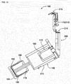
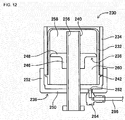
- fig. 12 shows solder supply device 230 that ejects solder paste by the moving of a supply nozzle.
- Solder supply device 230 has solder cup 232, outer tube 234, piston 236, fixed lid 238, and nozzle pipe 240.
- Solder cup 232 has the same form as solder cup 70 of the first embodiment. That is, solder cup 232 is a bottomed cylindrical container with an opening at one end and with flange section 242 formed on the outer circumferential surface at the opening side. Further, solder cup 232 is filled with solder paste.
- Outer tube 234 is a cylinder of which both ends are open; solder cup 232 is stored inside outer tube 234.
- the inside diameter of outer tube 234 is slightly smaller than the outer diameter of flange section 242 of solder cup 232, and slightly larger than the outer diameter of the tubular section of solder cup 232.
- the end of the bottom side of solder cup 232 is engaged from the end of outer tube 234 such that solder cup 232 is stored in outer tube 234.
- the section of solder cup 232 further to the side of the opening than flange section 242 extends from the opening of outer tube 234.
- piston 236 is configured from cylindrical section 246 and flange section 248; cylindrical section 246 and flange section 248 are formed as one body from material that is elastically deformable.
- Flange section 248 extends in a disk shape from the outer circumferential surface of an end of cylindrical section 246; the outer diameter of flange section 248 is slightly larger than the inside diameter of solder cup 232.
- flange section 248 is engaged inside solder cup 232 such that cylindrical section 246 faces the opening side of solder cup 232, and slides inside solder cup 232 while elastically deformed.
- fixed lid 238 has ring section 250, and erected section 252 established around the entire circumference at the outer edge of ring section 250.
- a screw thread (not shown) is formed on the inner circumferential surface of erected section 252, the screw thread being engaged with the screw thread (not shown) formed at the outer circumferential surface of an end of outer tube 234.
- nozzle pipe 240 is substantially cylindrical with nozzle hole 256 formed running through the inside.
- the outer diameter of nozzle pipe 240 is approximately the same as the inside diameter of ring section 250 of fixed lid 238, and nozzle pipe 240 is inserted into ring section such that nozzle pipe 240 and ring section 250 are fixed together.
- the end of nozzle pipe 240 fixed to ring section 250 extends from fixed lid 238, and the other end is inserted into outer tube 234, in other words, is inserted into solder cup 232 housed in outer tube 234.
- Nozzle pipe 240 inserted into solder cup 232 is engaged inside cylindrical section 246 of piston 236 housed inside solder cup 232.
- the inside diameter of cylindrical section 246 is slightly smaller than the outer diameter of nozzle pipe 240.
- cylindrical section 246 slides across the outer circumferential surface of nozzle pipe 240 in an elastically deformed state.
- solder cup 232 by an end of outer tube 234 being closed by fixed lid 238, the inside of solder cup 232 is demarcated into upper chamber 258 and lower chamber 260 by piston 236.
- Upper chamber 258 of solder cup 232 is filled with solder paste.
- nothing is filled in lower chamber 260, but through-hole 262 is formed in fixed lid 238, and through-hole 262 is formed in lower chamber 260.
- Air adapter 264 is attached to the through-hole 262.
- Air adapter 264 is connected to an end of air tube 266, and the other end of air tube 266 is connected to air supply device (refer to fig. 4 ) 122.
- solder supply device 230 by supplying air from air supply device 122, solder paste is ejected from nozzle hole 256 of nozzle pipe 240.
- air is supplied from air supply device 122, via air tube 266 and air adapter 264, to lower chamber 260.
- the lower chamber 260 side surface of piston 236, that is the surface of piston 236 facing the opening of solder cup 232 is pressed towards the bottom surface of solder cup 232, and piston 236 moves up.
- the solder paste inside upper chamber 258 is compressed and is ejected from nozzle hole 256 at the tip of nozzle pipe 240 that extends from fixed lid 238.
- solder supply device 230 by an end of outer tube 234 being closed by fixed lid 238, the inside of solder cup 232 is demarcated into upper chamber 258 and lower chamber 260 by piston 236. Further, upper chamber 258 is filled with solder paste, with lower chamber 260 functioning as an air chamber. That is, by the lower chamber side surface of piston 236 being directly pressed by air, solder paste inside upper chamber 258 is ejected from nozzle hole 256.
- solder supply device 230 of the third embodiment in a similar manner to solder supply device 26 of the first embodiment and solder supply device 160 of the second embodiment, it is not necessary to provide a cylinder device or the like, and the same effects as solder supply device 26 and solder supply device 160 are achieved.
- fixed lid 238 is rotated counterclockwise with respect to outer tube 234, so as to release the engagement of fixed lid 238 and outer tube 234.
- fixed lid 238 and nozzle pipe 240 are removed from outer tube 234.
- piston 236 engaged with nozzle pipe 240 is also removed from outer tube 234 together with nozzle pipe 240 by the friction arising between nozzle pipe 240 and ring section 246 of piston 236.
- solder cup 232 engaged with piston 236 is also removed from outer tube 234 together with piston 236 by the friction arising between flange section 248 of piston 236 and solder cup 232.
- fixed lid 238, nozzle pipe 240, piston 236, and solder cup 232 are removed as one from outer tube 234.
- solder cup 232 only is separated from the integrated body of fixed lid 238, nozzle pipe 240, piston 236, and solder cup 232. This is due to the friction arising between nozzle pipe 240 and cylindrical section 246 of piston 236.
- cylindrical section 246 of piston 236, as described above, is elastically deformed at the outer circumferential surface of nozzle pipe 240, and friction arises between cylindrical section 246 and nozzle pipe 240.
- flange section 248 of piston 236, as described above, is elastically deformed at the inside circumferential surface of solder cup 232, and friction arises between flange section 248 and solder cup 232; however, that friction is smaller than the friction that arises between cylindrical section 246 and nozzle pipe 240.
- piston 236 is removed from solder cup 232 together with nozzle pipe 240.
- solder cup exchange is completed by the integrated body of fixed lid 238, nozzle pipe 240, and piston 236 being attached to outer tube 234 that is engaged with the new solder cup. In this way, with solder supply device 230 of the third embodiment as well, solder cup exchange can be performed with relatively few steps, which means solder cup exchange work can be performed in a short time.
- solder supply device 230 of the third embodiment may be attached to X-axis slider 60 instead of solder supply device 26 of the first embodiment. By this, removing solder supply device 230 from solder printer 10 is easy, and the same effects as solder supply device 26 are achieved.
- solder printer 10 is an example of a solder printer.
- Solder supply device 26 is an example of a solder supply device.
- Solder cup 70 is an example of a solder container.
- Outer tube 72 is an example of an outer tube and a demarcating member.
- Inner tube 76 is an example of an inner tube.
- Space 86 is an example of an air chamber.
- Nozzle section 88 is an example of a nozzle.
- Flange section 90 is an example of a piston.
- Clip lock 130 is an example of a lock mechanism.
- Solder supply device 160 is an example of a solder supply device.
- Solder cup 162 is an example of a solder container.
- Adapter 164 is an example of an adapter.
- Outer tube 166 is an example of an outer tube and a demarcating member.
- Inner tube 170 is an example of an inner tube.
- Space 177 is an example of an air chamber.
- Nozzle section 178 is an example of a nozzle.
- Flange section 180 is an example of a piston.
- Solder supply device 230 is an example of a solder supply device.
- Solder cup 232 is an example of a solder container.
- Piston 236 is an example of a piston.
- Fixed lid 238 is an example of a lid and a demarcating member.
- Nozzle pipe 240 is an example of a nozzle.
- Lower chamber 260 is an example of an air chamber.
- clip lock 130 is used as a lock mechanism for detachably attaching solder supply device 26 to X-axis slider 60, but various lock mechanisms may be used.
- it is desirable to use a lock mechanism for which solder supply device 26 is attached/removed to/from X-axis slider 60 with a single touch that is, it is desirable to use a lock mechanism for which the repeatability of attaching/removing solder supply device 26 is good.
- fixed lid 238 is engaged with outer tube 234, but the fixed lid may be engaged with solder cup 232.
- outer tube 234 is not required, which reduces costs.
Description
- The present invention relates to a solder supply device for supplying liquid solder from a solder container housing liquid solder, the solder container being tubular and open at one end.
- As disclosed in patent literature 1 listed below, there are solder supply devices that supply liquid solder from a solder container by increasing the pressure inside the solder container using an air cylinder. Also, as disclosed in patent literature 2, there are devices that supply liquid solder from a solder container by operating a mechanism that increases the pressure inside the solder container using an electromagnetic motor. Patent literature 1 and 3 respectively disclose a solder supply device according to the preamble of claim 1.
-
- Patent literature 1:
JP-A-2003-311930 - Patent literature 2:
JP-A-2004-306102 - Patent literature 3 :
JP-A-2005-096126 - According to the solder supply devices disclosed in the above patent literature, it is possible to supply liquid solder from a solder container. However, in the solder supply devices disclosed in the above patent literature, an air cylinder or an electromagnetic motor must be provided, making the construction of the solder supply device complex. Also, space is required for the air cylinder or the electromagnetic motor making the solder supply device larger. The present invention takes account of such problems and an object thereof is to provide a solder supply device that supplies liquid solder from a solder container without using an air cylinder or an electromagnetic motor.
- To solve the above problems, a solder supply device according to claim 1 is provided.
- Further preferred embodiments of the invention are defined in the appended dependent claims 2 to 9.
- In the solder supply device disclosed in claim 1, the nozzle for ejecting solder in the solder container to the outside of the device is inserted into the solder container. A piston is provided on an outer circumferential section of the nozzle and that piston is engaged inside the solder container from the opening of the solder container. Also, a demarcating member is provided on the solder supply device, such that an air chamber is demarcated by the demarcating member and one out of the surface of the other end of the solder container, an adapter attached to the surface of the other end, and a surface of the piston facing the opening of the solder container. Also, solder is supplied from the tip of the nozzle by relatively moving the solder container and the piston by air being supplied to the air chamber. In other words, the bottom surface of the solder container or an adapter attached to the bottom surface of the solder container is directly pressed by the air, thus moving the solder container towards the piston. By this, the pressure inside the solder container increases and solder is supplied from the solder container. Also, the piston moves towards the bottom surface of the solder container by the piston engaged inside the solder container being pressed directly by air. By this, the pressure inside the solder container increases and solder is supplied from the solder container. Thus, according to the solder supply device disclosed in claim 1, solder can be supplied from a solder container without requiring an air cylinder or an electromagnetic motor.
- Also, with the solder supply device disclosed in claim 2, the piston is relatively movable to the nozzle. Further, a lid that seals the opening of the solder container in a state with the tip of the nozzle inserted functions as a demarcating member. By this, the air chamber is demarcated by the piston and the lid, and the piston is moved appropriately by the air pressure.
- Also, with the solder supply device disclosed in claim 3, the piston is fixedly provided on the outer circumferential section of the nozzle. Further, an outer tube with an opening at one end and that stores the solder container in a state with the other end of the solder container engaged from the opening functions as a demarcating member. By this, the air chamber is demarcated by the bottom surface of the solder container and the outer tube, or the outer tube and the adapter attached to the bottom surface of the solder, and the solder container is moved appropriately by the air pressure.
- Also, with the solder supply device disclosed in claim 4, an inner tube with an opening at both ends is provided. This inner tube holds the piston or the nozzle at one end, extends from the opening of the solder container at the other end, and is fixed to the outer tube. By this the piston or the nozzle is fixedly held, and the solder container is able to be moved appropriately towards the piston.
- Also, with the solder supply device disclosed in claim 5, the inner tube is separable from the piston or nozzle. That is, the piston or the nozzle, which directly contact solder, are able to be removed from the inner tube. This means that it is easy to wash the piston and nozzle, which easily become dirty, individually.
- Also, with the solder supply device disclosed in claim 6, the surface opposite to the opening of the outer tube is openable/closable. By this, for example, by opening that surface, the solder container and so on is able to be removed from the opened location, which facilitates the performance of exchange work and so on of the solder container.
- Also, with the solder supply device disclosed in claim 7, the outer tube is swingably attached to a solder printer. That is, the solder supply device provided at a specified location on a solder printer is able to be inclined. By this, for example, by opening the surface of the outer tube opposite to the opening, and making the opened location face down, the solder container in the outer tube is ejected from the outer tube by gravity. Thus, according to the solder supply device disclosed in claim 7, it is easy to remove the solder container from the outer tube.
- Also, with the solder supply device disclosed in claim 8, the friction arising between the outer circumferential section of the piston and the inner circumferential surface of the solder container is greater than the holding force of the piston or the nozzle by the inner tube. Thus, when the solder container in the outer tube is ejected from the outer tube by gravity by opening the surface of the outer tube opposite to the opening, and making the opened location face down, the nozzle and the piston inside the solder container are removed from the outer tube along with the solder container. This facilitates the efficient performing of exchange work and so on of the solder container.
- Also, the solder supply device disclosed in claim 9 is detachably mounted on a solder printer by a lock mechanism. Thus, the solder supply device is able to be removed from the solder printer simply by releasing the lock mechanism, facilitating the performing of exchange work and so on of the solder container outside the printer. This curtails the inside of the printer becoming dirty due to fallen solder and so on during solder container exchange. Also, the exchange work is performed outside the solder printer, not in the narrow space inside the solder printer, thus making exchange work easy to perform.
-
- [
Fig. 1 ]
Fig. 1 is a plan view showing a solder printer of a first embodiment of the invention. - [
Fig. 2 ]
Fig. 2 is a cross-section view showing a solder supply device provided in the solder printer offig. 1 . - [
Fig. 3 ]
Fig. 3 is a perspective view showing the solder supply device offig. 2 . - [
Fig. 4 ]
Fig. 4 is a block diagram showing the control device provided in the solder printer offig. 1 . - [
Fig. 5 ]
Fig. 5 is a cross-section view showing the solder supply device with the outer tube removed. - [
Fig. 6 ]
Fig. 6 is a cross-section view showing the solder supply device with the solder cup removed. - [
Fig. 7 ]
Fig. 7 is a cross-section view showing the solder supply device with a new solder cup housed inside the outer tube. - [
Fig. 8 ]
Fig. 8 is a cross-section view of the solder supply device exchanged with a new solder cup. - [
Fig. 9 ]
Fig. 9 is a cross-section view showing a second embodiment of a solder supply device. - [
Fig. 10 ]
Fig. 10 is a cross-section view showing the solder supply device offig. 9 when the cup is empty. - [
Fig. 11 ]
Fig. 11 is a cross-section view showing the solder supply device offig. 10 in a swung state. - [
Fig. 12 ]
Fig. 12 is a cross-section view showing a third embodiment of a solder supply device. - The following describes in detail referring to the figures example embodiments of the present invention.
-
Fig. 1 showssolder printer 10 as an embodiment of the invention.Solder printer 10 is a device that prints solder paste onto a circuit board.Solder printer 10 is provided withconveyance device 20, movingdevice 22,squeegee device 24, andsolder supply device 26. -
Conveyance device 20 has a pair ofconveyor belts 30 that extend in the X-axis direction, and electromagnetic motor (refer tofig. 4 ) 32 that rotatesconveyor belts 30. The pair ofconveyor belts 30support circuit board 34 andcircuit board 34 is conveyed in the X-axis direction by the driving ofelectromagnetic motor 32. Also,conveyance device 20 has holding device (refer tofig. 4 ) 36. Holdingdevice 36 fixedly holdscircuit board 34 supported byconveyor belts 30 in a predetermined position (the position at whichcircuit board 34 is shown infig. 1 ). Note that a metal mask (not shown) is loaded on the upper surface ofcircuit board 34. - Moving
device 22 is configured from Y-axisdirection slide mechanism 50 and X-axisdirection slide mechanism 52. Y-axisdirection slide mechanism 50 has Y-axis slider 56 provided onbase 54 so as to be movable in the Y-axis direction. Y-axis slider 56 is moved to any position in the Y-axis direction by the driving of electromagnetic motor (refer tofig. 4 ) 58. Also, X-axisdirection slide mechanism 52 hasX-axis slider 60 provided on a side surface of Y-axis slider 56 to be movable in the X-axis direction.X-axis slider 60 is moved to any position in the X-axis direction by the driving of electromagnetic motor (refer tofig. 4 ) 62. -
Squeegee device 24 is attached to Y-axis slider 56 aboutconveyance device 20, and moves to any position abovecircuit board 34 that is held byconveyance device 20.Squeegee device 24 has a squeegee (not shown) and the squeegee is held extending downwards bysqueegee device 24 to be movable in the Y-axis direction and the up/down directions. Further, the squeegee is moved in the Y-axis direction by the driving of electromagnetic motor (refer tofig. 4 ) 66, and is moved up/down by the driving of electromagnetic motor (refer tofig. 4 ) 68. -
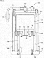
Solder supply device 26 is attached toX-axis slider 60 and is moved to any position abovebase 54 by movingdevice 22. As shown infig. 2 ,solder supply device 26 hassolder cup 70,outer tube 72,supply nozzle 74,inner tube 76, and fixedlid 78.Solder cup 70 is a bottomed cylindrical container with an opening at one end;solder cup 70 is filled with solder paste.Flange section 80 is formed on the outer circumferential surface at the opening side ofsolder cup 70; a screw thread (not shown) is formed betweenflange 80 and the edge of the opening side.Solder cup 70 is sold commercially with a lid (not shown) that engages with the screw thread covering the opening. That is, solder paste manufacturers sellsolder cups 70 after fillingsolder cups 70 with solder paste and covering the opening with a lid. Users purchase solder cups 70 and use them with the lid removed. - Also,
outer tube 72 is a bottomed cylinder with an opening at one end;solder cup 70 is stored insideouter tube 72. In detail, the inner circumferential surface ofouter tube 72 is configured from first innercircumferential surface 82 that is positioned at the opening side ofouter tube 72, and second innercircumferential surface 84 that is positioned atbottom surface 83 ofouter tube 72. The inside diameter of first innercircumferential surface 82 is slightly larger than the outer diameter offlange section 80 ofsolder cup 70; the inside diameter of second innercircumferential surface 84 is slightly larger than the outer diameter of the tubular section ofsolder cup 70. Further, the end of the bottom side ofsolder cup 70 is engaged from the opening ofouter tube 72 such thatsolder cup 70 is stored inouter tube 72. By this,solder cup 70 is slidable insideouter tube 72. However, the depth dimension of a portion of second innercircumferential surface 84 ofouter tube 72 is longer than the length dimension fromflange section 80 ofsolder cup 70 to the bottom surface, andflange section 80 ofsolder cup 70 stored inouter tube 72 contacts the step surface between first innercircumferential surface 82 and second innercircumferential surface 84 ofouter tube 72. Therefore,space 86 is formed between the bottom surface ofsolder cup 70 andbottom surface 83 ofouter tube 72. Note that, herein, the bottom surface refers to the surface on the opposite side to the opening of a bottomed cylindrical member. In other words, even if the surface on the opposite side to the opening of a bottomed cylindrical member is positioned towards the top, and the opening is positioned towards the bottom, the surface on the opposite side to the opening is given as the bottom surface, not the lid. - Also,
supply nozzle 74 is configured fromnozzle section 88 andflange section 90;nozzle section 88 andflange section 90 are formed as one body from material that is elastically deformable.Nozzle section 88 is substantially cylindrical withnozzle hole 92 formed running through the inside.Flange section 90 extends in a disk shape from the outer circumferential surface of an end of the nozzle section; the outer diameter offlange section 90 is slightly larger than the inside diameter ofsolder cup 70. Also,flange section 90 is engaged insidesolder cup 70 such thatnozzle section 88 faces the opening side ofsolder cup 70;supply nozzle 74 slides insidesolder cup 70 with the outer circumferential section offlange section 90 elastically deformed. - Further,
inner tube 76 hascylindrical tube section 96, andring section 98 that covers the edge oftube section 96;supply nozzle 74 is held byring section 98. In detail, the outer circumferential surface ofnozzle section 88 ofsupply nozzle 74 is configured from firstouter surface 100 positioned on theflange section 90 side and second outercircumferential surface 102 positioned at the tip side ofnozzle section 88; the outer diameter of firstouter diameter surface 100 is smaller than the outer diameter of second outercircumferential surface 102. On the other hand, the inside diameter ofring section 98 ofinner tube 76 is slightly larger than the outer diameter of first outercircumferential surface 100 and slightly smaller than the outer diameter of second outercircumferential surface 102. Also,nozzle section 88 engages with the inside diameter section ofring section 98 while a portion of secondcircumferential surface 102 is elastically deformed, and the inside diameter ofring section 98 and outercircumferential surface 100 ofnozzle section 88 engage. By this,inner tube 76 holdssupply nozzle 74 usingring section 98. Note that,inner tube 76 holdssupply nozzle 74 usingring section 98, thereforeinner tube 76 is positioned insidesolder cup 70; however, the end of the side not positioned atring section 98 oftube section 96 extends from the opening ofsolder cup 70. - Also, by pulling
supply nozzle 74 away frominner tube 76, a portion of secondouter circumferential 102 ofnozzle section 88 is elastically deformed such thatsupply nozzle 74 can be removed frominner tube 76. However, the force required to elastically deform the portion of second outercircumferential surface 102 ofnozzle section 88 when removingsupply nozzle 74 frominner tube 76, that is the holding force ofsupply nozzle 74 byinner tube 76, is larger than the friction that arises betweenflange section 90 ofsupply nozzle 74 engaged insidesolder cup 70 and the inner circumferential surface ofsolder cup 70. Thus, wheninner tube 76 holdingsuction nozzle 74 is pulled in a direction away fromsolder cup 70,supply nozzle 74 is not separated frominner tube 76, and is removed fromsolder cup 70 together withinner tube 76. - Further, fixed
lid 78 hasring section 106, and erectedsection 108 established around the entire circumference at the outer edge ofring section 106. A screw thread (not shown) is formed on the inner circumferential surface of erectedsection 108, the screw thread being engaged with the screw thread (not shown) formed at the opening end side ofouter tube 72. By this, fixedlid 78 is removably attached to the opening ofouter tube 72. Also, the inside diameter ofring section 106 is substantially the same as the inside diameter oftube section 96 ofinner tube 76, and the end section that extends fromsolder cup 70 oftube section 96 is fixed to the inside edge ofring section 106. Thus, by removing fixedlid 78 fromouter tube 72,inner tube 76 is also removed from insideouter tube 72. In this case,supply nozzle 74 held byinner tube 76 is also removed from insideouter tube 72. Further,solder cup 70 is also removed fromouter tube 72 by the friction arising betweenflange section 90 ofsupply nozzle 74 and the inner circumferential surface ofsolder cup 70. That is, by removing fixedlid 78 fromouter tube 72,inner tube 76,supply nozzle 74, andsolder cup 70 are removed as one fromouter tube 72. - Also, through-
hole 110 is formed inbottom surface 83 ofouter tube 72, andair adapter 112 is attached in through-hole 110.Air adapter 112 is connected to an end ofair tube 114, and the other end ofair tube 114 is connected to device-side air coupler 116. By connecting slider-side air coupler (refer tofig. 3 ) 118 provided at the arrangement position ofsolder supply device 26 to device-side air coupler 116, air is supplied tospace 86 insideouter tube 72, and solder paste is ejected fromnozzle hole 92 ofsupply nozzle 74. - In detail, as shown in
fig. 3 , an end ofair tube 120 is connected to slider-side air coupler 118, and the other end ofair tube 120 is connected to air supply device (refer tofig. 4 ) 122. By this, air is supplied fromair supply device 122 tospace 86 insideouter tube 72. When air is supplied tospace 86, the bottom surface ofsolder cup 70 is pressed towardssupply nozzle 74 andsolder cup 70 moves down. In this case, the solder paste fillingsolder cup 70 is compressed and is ejected fromnozzle hole 92 ofsupply nozzle 74. Solder paste ejected fromnozzle hole 92 passes throughtube section 96 ofinner tube 76, and the inner section ofring section 106 of fixedlid 78, and is ejected to the outside ofsolder supply device 26. Thus,solder supply device 26 supplies solder paste. In this way, withsolder supply device 26,space 86 is demarcated by the bottom surface ofsolder cup 70 andbottom surface 83 ofouter tube 72, withspace 86 functioning as an air chamber. That is, by the bottom surface ofsolder cup 70 being directly pressed by air, solder paste insidesolder cup 70 is ejected fromnozzle hole 92. Thus, withsolder supply device 26, it is not necessary to provide a cylinder device for pushingsolder cup 70, andsolder supply device 26 can be made more compact. Also, because there is no need to provide a cylinder device, costs are reduced. Further, because there is no need to provide a cylinder device, the configuration ofsolder supply device 26 can be made simple. - Also, as shown in
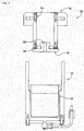
fig. 3 ,solder supply device 26 is detachably mounted onX-axis slider 60 byclip lock 130. In detail,bracket 132 is attached to the lower end ofX-axis slider 60, and the lower surface ofsolder supply device 26 is supported bybracket 132. In other words,solder supply device 26 is able to be loaded onbracket 132. Note that, a through-hole approximately the same as the inner diameter ofring section 106 of fixedlid 78 ofsolder supply device 26 is formed inbracket 132. By this, solder paste is supplied fromsolder supply device 26 loaded onbracket 132 via the through-hole inbracket 132. - Two surrounding
plates X-axis slider 60 abovebracket 132 facing each other and perpendicular tobracket 132. The distance between the two surroundingbrackets outer tube 72 ofsolder supply device 26, andsolder supply device 26 is loaded between the two surroundingplates closing plate 140 is attached to surroundingplate 134 viahinge 138.Lever section 146 ofclip lock 130 is provided on the other end of opening/closing plate 140, andhook stopper 148 ofclip lock 130 is provided on surroundingplate 136. Also, by performing locking with opening/closing plate 140 in a closed state andlever section 146 latched ontohook stopper 148,solder supply device 26 is fixedly mounted onX-axis slider 60. Also, by releasing the locking ofclip lock 130 and opening opening/closing plate 140,solder supply device 26 is able to be removed fromX-axis slider 60. Note that, device-side air coupler 116 and slider-side air coupler 118 are detachable, and device-side air coupler 116 is removed from slider-side air coupler 118 whensolder supply device 26 is removed fromX-axis slider 60. - Also, as shown in
fig. 4 ,solder printer 10 is provided withcontrol device 150.Control device 150 is provided with controller 152 andmultiple drive circuits 154.Multiple drive circuits 154 are connected to the above-mentionedelectromagnetic motors device 36, andair supply device 122. Also, controller 152 is provided with a CPU, ROM or RAM, forming the main parts of a computer, and is connected to themultiple drive circuits 154. Thus, the operation ofconveyance device 20, movingdevice 22,squeegee device 24, andsolder supply device 26 is controlled by controller 152. - With
solder printer 10, according to the above-described configuration, solder paste is supplied onto the upper surface of a metal mask loaded oncircuit board 34 bysolder supply device 26, and that solder paste is applied bysqueegee device 24. Pattern holes matching the pattern of the pads and so on ofcircuit board 34 are formed in the metal mask, and solder paste is printed ontocircuit board 34 via the pattern holes. - Specifically, based on commands of controller 152,
circuit board 34 is conveyed to a work position, and fixedly held at that position by holdingdevice 36. Then,solder supply device 26, based on commands of controller 152, moves to a prescribed position abovecircuit board 34. Continuing, based on commands of controller 152,solder supply device 26 supplies air fromair supply device 122 intospace 86 insideouter tube 72. By this, solder paste is ejected fromnozzle hole 92, thus supplying solder paste onto the upper surface of the metal mask loaded oncircuit board 34. Next, based on commands of controller 152,squeegee device 24 is moved above the location where solder paste was supplied. Then, based on commands of controller 152,squeegee device 24 moves a squeegee down and then moves in the Y-axis direction. By this, solder paste is applied on the upper surface of the metal mask, and solder paste thus enters into the pattern holes. In this manner,solder printer 10 prints solder paste ontocircuit board 34. - When printing solder paste onto
circuit board 34 as described above, because solder paste is supplied fromsolder cup 70 ofsolder supply device 26,solder cup 70 empties. Thus, asolder cup 70 which has become empty must be exchanged for asolder cup 70 which is full of solder paste. The exchange procedure forsolder cup 70 is described below. - First, the locking of
clip lock 130 is released such that opening/closing plate 140 is able to be opened. Also, device-side air coupler 116 is removed from slider-side air coupler 118. Then,solder supply device 26 is removed fromX-axis slider 60 and removed fromsolder printer 10. Aftersolder supply device 26 has been removed from the printer, fixedlid 78 is rotated counterclockwise with respect toouter tube 72 to release the engagement of fixedlid 78 andouter tube 72. By this, as shown infig. 5 , fixedlid 78,inner tube 76,supply nozzle 74, andsolder cup 70 are removed as one fromouter tube 72. - Next, at least one of
solder cup 70 and fixedlid 78 is pulled away from the other. By this, as shown infig. 6 , fixedlid 78,inner tube 76, andsupply nozzle 74 are separated as one fromsolder cup 70. That is,supply nozzle 74 is removed from the inside ofempty solder cup 70 along withinner tube 76. - Continuing, as shown in
fig. 7 , anew solder cup 70, that is asolder cup 70 full of solder paste, is set insideouter tube 72. Then, withsupply nozzle 74 engaged inside thatsolder cup 70, fixedlid 78 is engaged with the opening ofouter tube 72. By this, as shown infig. 8 ,new solder cup 70 is set insidesolder supply device 26. - When
new solder cup 70 is set insolder supply device 26,solder supply device 26 is drawn intosolder printer 10 and loaded onbracket 132. Then opening/closing plate 140 is closed andclip lock 130 is locked. Also, device-side air coupler 116 is attached to slider-side air coupler 118. By this,solder supply device 26 is fixedly attached toX-axis slider 60, thereby completing exchange ofsolder cup 70. - In this way, with
solder printer 10, by the engaging of fixedlid 78 andouter tube 72, fixedlid 78,outer tube 72,inner tube 76,supply nozzle 74, andsolder cup 70 are integrated as one, thus an operator is able to holdsolder supply device 26 with one hand and easily remove it fromsolder printer 10. By this, it is possible to perform exchange ofsolder cup 70 outside ofsolder printer 10, which makes it possible to curtail getting the inside ofsolder printer 10 dirty due to fallen solder paste and so on during exchange. Also, the exchange work is performed outsidesolder printer 10, not in the narrow space insidesolder printer 10, thus making exchange work easy to perform. Further, cleaning ofsolder cup 70 and so on can also be performed outsidesolder printer 10, so cleaning work is also easy. Also, as given above,supply nozzle 74 is able to be removed frominner tube 76, sosupply nozzle 74, which is easily dirtied, is able to be cleaned individually. - Also, for example, by preparing another
solder supply device 26, it is possible to perform exchange of solder cups in an extremely short time. In detail, a solder supply device different tosolder supply device 26 attached toX-axis slider 60 is prepared, and, as shown infig. 8 , anew solder cup 70 is set in that different solder supply device. Then, exchange of solder cups is completed by removingsolder supply device 26 fromX-axis slider 60 and attaching the different solder supply device set with thenew solder cup 70 toX-axis slider 60. By this, it is possible to perform exchange of solder cups in an extremely short time. - In
solder printer 10 of the first embodiment,solder supply device 26 that is removable fromX-axis slider 60 is used, but a solder supply device for which the attaching/removing of a solder cup is easy may be used. As a second embodiment,fig. 9 showssolder supply device 160 for which the attaching/removing of a solder cup is easy. -
Solder supply device 160 hassolder cup 162,adapter 164,outer tube 166,supply nozzle 168,inner tube 170, and fixedlid 172.Solder cup 162 has the same form assolder cup 70 of the first embodiment That is,solder cup 162 is a bottomed cylindrical container with an opening at one end and with flange section 174 formed on the outer circumferential surface at the opening side.Solder cup 162 is filled with solder paste. -
Adapter 164 is also a bottomed cylinder with an opening at one end, andsolder cup 162 is stored insideadapter 164. In detail, the inside diameter ofadapter 164 is slightly smaller than the outer diameter of flange section 174 ofsolder cup 162, and slightly larger than the outer diameter of the tubular section ofsolder cup 162. Also, the end of the bottom side ofsolder cup 162 is engaged from the opening ofadapter 164 such thatsolder cup 162 is stored inadapter 164. Note that, the depth dimension ofadapter 164 is longer than the length dimension from flange section 174 ofsolder cup 162 to the bottom, and flange section 174 ofsolder cup 162 stored inadapter 164 contacts the opening end ofadapter 164. Thus, the section ofsolder cup 162 further to the side of the opening than flange section 174 extends from the opening ofadapter 164. - Also,
outer tube 166 is a bottomed cylinder with an opening at one end;adapter 164 is stored insideouter tube 166. In detail, the inside diameter ofouter tube 166 is slightly larger than the outer diameter ofadapter 164. Further, the bottom surface ofadapter 164 andbottom surface 175 ofouter tube 166 are facing each other and engaged such thatadapter 164 is stored inouter tube 166. By this,adapter 164 is slidable insideouter tube 166. Note that,recess 176 is formed in a center section on the inside ofbottom surface 175 ofouter tube 166;space 177 is demarcated byrecess 176 and the bottom surface ofadapter 164. - Also,
supply nozzle 168 is configured fromnozzle section 178 andflange section 180;nozzle section 178 andflange section 180 are formed as one body from material that is elastically deformable.Nozzle section 178 is substantially cylindrical withnozzle hole 182 formed running through the inside.Flange section 180 extends in a disk shape from the outer circumferential surface of an end ofnozzle section 178; the outer diameter offlange section 180 is slightly larger than the inside diameter ofsolder cup 162. Also,flange section 180 is engaged insidesolder cup 162 such thatnozzle section 178 faces the opening side ofsolder cup 162;supply nozzle 168 slides insidesolder cup 162 with the outer circumferential section offlange section 180 elastically deformed. Note that, the length dimension ofnozzle section 178 is longer than the depth dimension ofsolder cup 162. Thus,supply nozzle 168 andsolder cup 162 move relative to each other, and, as shown infig. 10 , even whenflange section 180 is close to the bottom surface ofsolder cup 162, the tip ofnozzle section 178 extends from the opening ofsolder cup 162. - Also, as shown in
fig. 9 ,inner tube 170 hascylindrical tube section 186 andring section 188 that covers the edge oftube section 186. The inside diameter ofring section 188 is slightly larger than the outer diameter ofnozzle section 178 ofsupply nozzle 168. Further,nozzle section 178 is inserted in the inside diameter section ofring section 188, andinner tube 170 supportssupply nozzle 168 withflange section 180 ofsupply nozzle 168 contactingring section 188. Also, the length dimension ofnozzle section 178 is longer than the length ofinner tube 170. By this,nozzle section 178 passes through the inside ofinner tube 170, and the tip ofnozzle section 178 extends from the end ofinner tube 170 opposite to ringsection 188. - Also, fixed
lid 172 is disk-shaped, with through-hole 190 formed in a center section.Fixed lid 172 is fixed to the opening end ofouter tube 166, and covers the opening ofouter tube 166. Also, inside ofouter tube 166,inner tube 170 is fixed to fixedlid 172 at the end opposite toring section 188, and the tip ofnozzle section 178 ofsupply nozzle 168 supported byinner tube 170 is inserted inside through-hole 190. Note that, the inside diameter of through-hole 190 is larger than the outer diameter ofnozzle section 178. - Also, through-
hole 200 is formed inrecess 176 ofbottom surface 175 ofouter tube 166, andair adapter 202 is attached in through-hole 200.Air adapter 202 is connected to an end ofair tube 204, and the other end ofair tube 204 is connected to air supply device (refer tofig. 4 ) 122. According to this kind of configuration, withsolder supply device 160, by supplying air fromair supply device 122 to the inside ofouter tube 166, solder paste is ejected fromnozzle hole 182 ofsupply nozzle 168. - In detail, air is supplied from
air supply device 122, viaair tube 204 andair adapter 202, to space 177 insideouter tube 166. When air is supplied tospace 177, the bottom surface ofadapter 164 is pressed towardssupply nozzle 168 andadapter 164 moves down. In this case,solder cup 162 also moves down withadapter 164 such that the solder paste insolder cup 162 is compressed. By this, solder paste is ejected fromnozzle hole 182 ofsupply nozzle 168. - In this way, with
solder supply device 160,space 177 is divided by the bottom surface ofadapter 164 that housessolder cup 162 andrecess 176 ofouter tube 166, withspace 177 functioning as an air chamber. That is, by the bottom surface of adapter that housessolder cup 162 being directly pressed by air, solder paste insidesolder cup 162 is ejected fromnozzle hole 182. Thus, withsolder supply device 160 as well, in a similar manner to soldersupply device 26 of the first embodiment, it is not necessary to provide a cylinder device for pushingsolder cup 162, and the same effects assolder supply device 26 of the first embodiment are achieved. - Also, with
solder supply device 160,bottom surface 175 ofouter tube 166 is capable of opening/closing, such thatouter tube 166 is capable of swinging. Thus,solder cup 162 can be easily removed/inserted from/intobottom surface 175. In detail,outer tube 166 is held by holdingunit 208; holdingunit 208 is detachably mounted onX-axis slider 60. Also,outer tube 166 is configured from two members -cylindrical member 210 and bottom member 212 - andbottom member 212 is attached to the top end of holdingunit 208 viahinge 214. By this,bottom member 212 opens/closes, such that the top side ofcylindrical member 210 is opened or closed. Also,lever section 218 and joint 220 of clippinglock 216 are formed onbottom member 212, andhook stopper 222 ofclip lock 216 is provided on the upper end ofcylindrical member 210. Further, withbottom member 212 closed, joint 220 hooks ontohook stopper 222, andclip lock 216 is locked by the operation oflever section 218. By this,bottom member 212 adheres to the upper end ofcylindrical member 210 andspace 177 is sealed closed. Also, by releasing the lock ofclip lock 216 by the operation oflever section 218,bottom member 212 is opened, and the upper end ofcylindrical member 210 is opened too. - Also,
outer tube 166 is swingably held by holdingunit 208. Thus, for example, when the solder paste insolder cup 162 has run out (refer tofig. 10 ), by the lock ofclip lock 216 being released andbottom member 212 being able to be opened,outer tube 166 swings, as shown infig. 11 . By this,outer tube 166 is titled 90 degrees or more, and the upper end ofouter tube 166 faces down. Due to this,adapter 164 housed insideouter tube 166 is ejected from the upper end ofouter tube 166 by gravity. In this case,solder cup 162 housed insideadapter 164 is also ejected from the upper end ofouter tube 166 along withadapter 164 due to gravity. - Also, supply nozzle 16 housed inside
solder cup 162 is ejected together withsolder cup 162 from the upper end ofouter tube 166 by the friction arising betweenflange section 180 ofsupply nozzle 168 and the inner circumferential surface ofsolder cup 162. In detail,flange section 180, as described above, is elastically deformed insidesolder cup 162, friction arises betweenflange section 180 and the inner circumferential surface ofsolder cup 162. Conversely, virtually no friction arises betweennozzle section 178 ofsupply nozzle 168 andring section 188 ofinner tube 170 holdingnozzle section 178. This is because the inside diameter ofring section 188 is slightly larger than the outer diameter ofnozzle section 178. Thus, the friction arising betweenflange section 180 and the inner circumferential surface ofsolder cup 162 is bigger than the friction arising betweennozzle section 178 andring section 188, in other words, the holding force ofnozzle section 178 byring section 188. By this,supply nozzle 168 is ejected together withsolder cup 162 from the upper end ofouter tube 166. - In this way, with
solder supply device 160, the upper end ofouter tube 166 is open, so just by swingingouter tube 166,adapter 164,solder cup 162, andsupply nozzle 168 can be removed fromouter tube 166 as one body. By this, exchange of solder cups can be performed outside ofsolder printer 10, and the same effects assolder supply device 26 of the first embodiment are achieved. - Also, with exchange of solder cups of the second embodiment, the integrated body of
adapter 164,solder cup 162, andsupply nozzle 168, is divided intoadapter 164,solder cup 162, andsupply nozzle 168. Further, a new solder cup is engaged with the dividedadapter 164, andsupply nozzle 168 is engaged with that new solder cup. By this,adapter 164, the new solder cup, andsupply nozzle 168 form an integrated body. Further, the integrated body is housed insideouter tube 166, and byclip lock 216 being locked with the upper end ofouter tube 166 being closed bybottom member 212, exchange of solder cups is completed. In this way, withsolder supply device 160 of the second embodiment, compared tosolder supply device 26 of the first embodiment, the steps for exchanging solder cups are fewer, and solder cup exchange can be performed in a shorter time. - Further, with
solder supply device 160, by preparing anotheradapter 164 andsupply nozzle 168, it is possible to perform exchange of solder cups in an extremely short time. In detail, an adapter and supply nozzle different toadapter 164 andsupply nozzle 168 housed insideouter tube 166 are prepared. A new solder cup is engaged with that prepared adapter, and theprepared supply nozzle 168 is engaged with the new solder cup. By this, an integrated body of a different adapter, new solder cup, and supply nozzle are formed different to the integrated body ofadapter 164,solder cup 162, andsupply nozzle 168 housed insideouter tube 166. Further, after the integrated body ofadapter 164,solder cup 162, andsupply nozzle 168 housed insideouter tube 166 is removed fromouter tube 166, solder cup exchange is completed by the integrated body of the different adapter, new solder cup, and supply nozzle being housed insideouter tube 166. By this, it is possible to perform exchange of solder cups in an extremely short time. - Note that, with
solder supply device 26 of the first embodiment, it is necessary to prepare a solder supply device different tosolder supply device 26 in order to shorten the exchange time of solder cups; however, withsolder supply device 160 of the second embodiment, it is only necessary to prepare an adapter and supply nozzle different toadapter 164 andsupply nozzle 168. Thus, withsolder supply device 160 of the second embodiment, it is possible to shorten the exchange time for solder cups with a relatively low-cost investment. - Third embodiment With
solder supply devices solder cups fig. 12 showssolder supply device 230 that ejects solder paste by the moving of a supply nozzle. -
Solder supply device 230 hassolder cup 232,outer tube 234,piston 236, fixedlid 238, andnozzle pipe 240.Solder cup 232 has the same form assolder cup 70 of the first embodiment. That is,solder cup 232 is a bottomed cylindrical container with an opening at one end and withflange section 242 formed on the outer circumferential surface at the opening side. Further,solder cup 232 is filled with solder paste. -
Outer tube 234 is a cylinder of which both ends are open;solder cup 232 is stored insideouter tube 234. In detail, the inside diameter ofouter tube 234 is slightly smaller than the outer diameter offlange section 242 ofsolder cup 232, and slightly larger than the outer diameter of the tubular section ofsolder cup 232. Further, the end of the bottom side ofsolder cup 232 is engaged from the end ofouter tube 234 such thatsolder cup 232 is stored inouter tube 234. Note that, the section ofsolder cup 232 further to the side of the opening thanflange section 242 extends from the opening ofouter tube 234. - Also,
piston 236 is configured fromcylindrical section 246 andflange section 248;cylindrical section 246 andflange section 248 are formed as one body from material that is elastically deformable.Flange section 248 extends in a disk shape from the outer circumferential surface of an end ofcylindrical section 246; the outer diameter offlange section 248 is slightly larger than the inside diameter ofsolder cup 232. Also,flange section 248 is engaged insidesolder cup 232 such thatcylindrical section 246 faces the opening side ofsolder cup 232, and slides insidesolder cup 232 while elastically deformed. - Further, fixed
lid 238 hasring section 250, and erectedsection 252 established around the entire circumference at the outer edge ofring section 250. A screw thread (not shown) is formed on the inner circumferential surface of erectedsection 252, the screw thread being engaged with the screw thread (not shown) formed at the outer circumferential surface of an end ofouter tube 234. By this, fixedlid 238 is removably attached to the end ofouter tube 234. - Also,
nozzle pipe 240 is substantially cylindrical withnozzle hole 256 formed running through the inside. The outer diameter ofnozzle pipe 240 is approximately the same as the inside diameter ofring section 250 of fixedlid 238, andnozzle pipe 240 is inserted into ring section such thatnozzle pipe 240 andring section 250 are fixed together. Thus, the end ofnozzle pipe 240 fixed toring section 250 extends from fixedlid 238, and the other end is inserted intoouter tube 234, in other words, is inserted intosolder cup 232 housed inouter tube 234.Nozzle pipe 240 inserted intosolder cup 232 is engaged insidecylindrical section 246 ofpiston 236 housed insidesolder cup 232. The inside diameter ofcylindrical section 246 is slightly smaller than the outer diameter ofnozzle pipe 240. Thus,cylindrical section 246 slides across the outer circumferential surface ofnozzle pipe 240 in an elastically deformed state. - According to the above configuration, by an end of
outer tube 234 being closed by fixedlid 238, the inside ofsolder cup 232 is demarcated intoupper chamber 258 andlower chamber 260 bypiston 236.Upper chamber 258 ofsolder cup 232 is filled with solder paste. On the other hand, nothing is filled inlower chamber 260, but through-hole 262 is formed in fixedlid 238, and through-hole 262 is formed inlower chamber 260.Air adapter 264 is attached to the through-hole 262.Air adapter 264 is connected to an end ofair tube 266, and the other end ofair tube 266 is connected to air supply device (refer tofig. 4 ) 122. According to this kind of configuration, withsolder supply device 230, by supplying air fromair supply device 122, solder paste is ejected fromnozzle hole 256 ofnozzle pipe 240. - In detail, air is supplied from
air supply device 122, viaair tube 266 andair adapter 264, tolower chamber 260. When air is supplied tolower chamber 260, thelower chamber 260 side surface ofpiston 236, that is the surface ofpiston 236 facing the opening ofsolder cup 232, is pressed towards the bottom surface ofsolder cup 232, andpiston 236 moves up. Thus, the solder paste insideupper chamber 258 is compressed and is ejected fromnozzle hole 256 at the tip ofnozzle pipe 240 that extends from fixedlid 238. - In this way, with
solder supply device 230, by an end ofouter tube 234 being closed by fixedlid 238, the inside ofsolder cup 232 is demarcated intoupper chamber 258 andlower chamber 260 bypiston 236. Further,upper chamber 258 is filled with solder paste, withlower chamber 260 functioning as an air chamber. That is, by the lower chamber side surface ofpiston 236 being directly pressed by air, solder paste insideupper chamber 258 is ejected fromnozzle hole 256. Thus, withsolder supply device 230 of the third embodiment as well, in a similar manner to soldersupply device 26 of the first embodiment andsolder supply device 160 of the second embodiment, it is not necessary to provide a cylinder device or the like, and the same effects assolder supply device 26 andsolder supply device 160 are achieved. - Also, with solder cup exchange of the third embodiment, fixed
lid 238 is rotated counterclockwise with respect toouter tube 234, so as to release the engagement of fixedlid 238 andouter tube 234. By this, fixedlid 238 andnozzle pipe 240 are removed fromouter tube 234. Here,piston 236 engaged withnozzle pipe 240 is also removed fromouter tube 234 together withnozzle pipe 240 by the friction arising betweennozzle pipe 240 andring section 246 ofpiston 236. Further,solder cup 232 engaged withpiston 236 is also removed fromouter tube 234 together withpiston 236 by the friction arising betweenflange section 248 ofpiston 236 andsolder cup 232. By this, fixedlid 238,nozzle pipe 240,piston 236, andsolder cup 232 are removed as one fromouter tube 234. - Next, by pulling at least one of fixed
lid 238 andsolder cup 232 in a direction away from the other,solder cup 232 only is separated from the integrated body of fixedlid 238,nozzle pipe 240,piston 236, andsolder cup 232. This is due to the friction arising betweennozzle pipe 240 andcylindrical section 246 ofpiston 236. In detail,cylindrical section 246 ofpiston 236, as described above, is elastically deformed at the outer circumferential surface ofnozzle pipe 240, and friction arises betweencylindrical section 246 andnozzle pipe 240. Also,flange section 248 ofpiston 236, as described above, is elastically deformed at the inside circumferential surface ofsolder cup 232, and friction arises betweenflange section 248 andsolder cup 232; however, that friction is smaller than the friction that arises betweencylindrical section 246 andnozzle pipe 240. Thus,piston 236 is removed fromsolder cup 232 together withnozzle pipe 240. - In this way,
empty solder cup 232 is separated bypiston 236 being removed fromsolder cup 232. Next, a new solder cup is engaged with the separatedouter tube 234. Solder cup exchange is completed by the integrated body of fixedlid 238,nozzle pipe 240, andpiston 236 being attached toouter tube 234 that is engaged with the new solder cup. In this way, withsolder supply device 230 of the third embodiment as well, solder cup exchange can be performed with relatively few steps, which means solder cup exchange work can be performed in a short time. - Also,
solder supply device 230 of the third embodiment may be attached toX-axis slider 60 instead ofsolder supply device 26 of the first embodiment. By this, removingsolder supply device 230 fromsolder printer 10 is easy, and the same effects assolder supply device 26 are achieved. - Note that, in the above embodiments,
solder printer 10 is an example of a solder printer.Solder supply device 26 is an example of a solder supply device.Solder cup 70 is an example of a solder container.Outer tube 72 is an example of an outer tube and a demarcating member.Inner tube 76 is an example of an inner tube.Space 86 is an example of an air chamber.Nozzle section 88 is an example of a nozzle.Flange section 90 is an example of a piston.Clip lock 130 is an example of a lock mechanism.Solder supply device 160 is an example of a solder supply device.Solder cup 162 is an example of a solder container.Adapter 164 is an example of an adapter.Outer tube 166 is an example of an outer tube and a demarcating member.Inner tube 170 is an example of an inner tube.Space 177 is an example of an air chamber.Nozzle section 178 is an example of a nozzle.Flange section 180 is an example of a piston.Solder supply device 230 is an example of a solder supply device.Solder cup 232 is an example of a solder container.Piston 236 is an example of a piston.Fixed lid 238 is an example of a lid and a demarcating member.Nozzle pipe 240 is an example of a nozzle.Lower chamber 260 is an example of an air chamber. - Further, the present invention is not limited to the above example embodiments, and various changed or improved methods of embodiment are possible based on the knowledge of someone skilled in the art. Specifically, for example, in the first embodiment described above,
clip lock 130 is used as a lock mechanism for detachably attachingsolder supply device 26 toX-axis slider 60, but various lock mechanisms may be used. However, considering factors such as making exchange time short, it is desirable to use a lock mechanism for whichsolder supply device 26 is attached/removed to/fromX-axis slider 60 with a single touch, that is, it is desirable to use a lock mechanism for which the repeatability of attaching/removingsolder supply device 26 is good. Specifically, for example, it is desirable to use a magnetic or spring-type lock mechanism. - Also, with the third embodiment described above, fixed
lid 238 is engaged withouter tube 234, but the fixed lid may be engaged withsolder cup 232. In this way, when engaging the fixed lid withsolder cup 232,outer tube 234 is not required, which reduces costs. Also, when engaging the fixed lid withsolder cup 232, it is possible to use the screw thread formed in advance onsolder cup 232, that is, the screw thread with which the lid of the solder cup engages. By this, it is not necessary to form a screw thread in the solder cup, which reduces costs. - 10: solder printer; 26: solder supply device; 70: solder cup (solder container); 72: outer tube (demarcating member); 76: inner tube; 86: space (air chamber); 88: nozzle section (nozzle); 90: flange section (piston); 130: clip lock (lock mechanism); 160: solder supply device; 162: solder cup (solder container); 164: adapter; 166: outer tube (demarcating member); 170: inner tube; 177: space (air chamber); 178: nozzle section (nozzle); 180: flange section (piston); 230: solder supply device; 232: solder cup (solder container); 236: piston; 238: fixed lid (lid) (demarcating member); 240: nozzle pipe (nozzle); 260: lower chamber (air chamber).
Claims (9)
- A solder supply device (26) comprising:a tubular solder container (70) housing liquid solder, the solder container (70) being open at one end and closed at the other end;a nozzle (88), for ejecting solder from the solder container (70); anda piston (90);the nozzle (88) being inserted into the open end of the solder container (70); the piston (90) being provided on an outer circumferential section of the nozzle (88) and engaged inside of the solder container (70) from the open end of the solder container (70); characterized in thata demarcating member (83, 238, 72) is provided that demarcates an air chamber (86) with at least one out of a surface of the closed end of the solder container (70), an adapter (164) attached to the surface of the closed end of the solder container (70), and a surface of the piston (90) facing the opening of the solder container (70), andthe solder supply device (26) supplies solder from the tip of the nozzle (88) by relatively moving the solder (70) container and the piston (90) by the supplying of air to the air chamber (86).
- The solder supply device (26) according to claim 1, wherein
the piston (90) is provided on the outer circumferential section of the nozzle (88) relatively movable to the nozzle (88),
the solder supply device (26) is further provided with a lid (238) that seals the opening of the solder container (70) in a state with the tip of the nozzle (88) inserted into the solder container (70), and
the lid (238) functions as the demarcating member. - The solder supply device (26) according to claim 1, wherein
the piston (90) is fixedly provided on the outer circumferential surface of the nozzle (88), the solder supply device (26) is further provided with an outer tube (72) with an opening at one end and that stores the solder container (70) in a state with the closed end of the solder container (70) engaged from the opening, and
the outer tube (72) functions as the demarcating member. - The solder supply device (26) according to claim 3, wherein
the solder supply device (26) is further provided with an inner tube (76) with a first open end and a second open end, the first open end holding the piston (90) or the nozzle (88), the second open end extending from the open end of the solder container (70), and the inner tube (76) being fixed to the outer tube (72). - The solder supply device (26) according to claim 4, wherein
the inner tube (76) is separable from the piston (90) or the nozzle (88). - The solder supply device (26) according to claim 4 or 5, wherein
the surface of the other end of the outer tube (72) is openable/closable. - The solder supply device (26) according to claim 6, wherein
the outer tube (72) is swingably attached to a solder printer (10) that prints solder on a target object. - The solder supply device (26) according to claim 6 or 7, wherein
the friction arising between the outer circumferential section of the piston (90) and the inner circumferential surface of the solder container (70) is greater than the holding force of the piston (90) or the nozzle (88) by the inner tube (76). - The solder supply device (26) according to any one of the claims 2 to 5, wherein
the solder supply device (26) is detachably mounted on a solder printer (10) that prints solder on a target object by a lock mechanism.
Applications Claiming Priority (1)
| Application Number | Priority Date | Filing Date | Title |
|---|---|---|---|
| PCT/JP2013/082709 WO2015083271A1 (en) | 2013-12-05 | 2013-12-05 | Solder supply device |
Publications (4)
| Publication Number | Publication Date |
|---|---|
| EP3078441A1 EP3078441A1 (en) | 2016-10-12 |
| EP3078441A4 EP3078441A4 (en) | 2017-08-30 |
| EP3078441B1 true EP3078441B1 (en) | 2018-09-19 |
| EP3078441B8 EP3078441B8 (en) | 2018-11-21 |
Family
ID=53273063
Family Applications (1)
| Application Number | Title | Priority Date | Filing Date |
|---|---|---|---|
| EP13898551.0A Active EP3078441B8 (en) | 2013-12-05 | 2013-12-05 | Solder supply device |
Country Status (5)
| Country | Link |
|---|---|
| US (1) | US9883597B2 (en) |
| EP (1) | EP3078441B8 (en) |
| JP (1) | JP6199988B2 (en) |
| CN (1) | CN105873709B (en) |
| WO (1) | WO2015083271A1 (en) |
Families Citing this family (7)
| Publication number | Priority date | Publication date | Assignee | Title |
|---|---|---|---|---|
| CN105792972B (en) * | 2013-12-18 | 2018-09-14 | 富士机械制造株式会社 | Solder feedway |
| KR102445985B1 (en) | 2017-04-14 | 2022-09-21 | 일리노이즈 툴 워크스 인코포레이티드 | Solder paste supply assembly and solder paste supply method |
| KR102455167B1 (en) * | 2017-04-14 | 2022-10-14 | 일리노이즈 툴 워크스 인코포레이티드 | Solder paste drip prevention device |
| DE102017221708A1 (en) * | 2017-12-01 | 2019-06-06 | Klebchemie, M.G. Becker Gmbh & Co Kg | Device and method for melting a hotmelt adhesive |
| JP6928018B2 (en) * | 2019-03-06 | 2021-09-01 | ファナック株式会社 | Robot device for soldering |
| EP3960459A4 (en) * | 2019-04-26 | 2022-05-11 | Fuji Corporation | Supply unit, printing device, and method for controlling printing device |
| CN111246724B (en) * | 2020-03-04 | 2021-06-01 | 环维电子(上海)有限公司 | Side clamp jig of electronic module and use method thereof |
Family Cites Families (25)
| Publication number | Priority date | Publication date | Assignee | Title |
|---|---|---|---|---|
| DE7603096U1 (en) * | 1976-02-04 | 1976-08-19 | Espe Pharm Praep | Device for the dosed delivery of viscous masses |
| JPS5866020A (en) * | 1981-10-15 | 1983-04-20 | Toshiba Corp | Constant quantity discharging device for liquid |
| JPS601573U (en) | 1983-06-16 | 1985-01-08 | 日本電気ホームエレクトロニクス株式会社 | Quantitative supply device for highly viscous sol-like substances mixed with powder |
| JPS601573A (en) * | 1983-06-17 | 1985-01-07 | Toyota Motor Corp | Abnormality detection circuit for sensor |
| US4622239A (en) * | 1986-02-18 | 1986-11-11 | At&T Technologies, Inc. | Method and apparatus for dispensing viscous materials |
| US4720402A (en) * | 1987-01-30 | 1988-01-19 | American Telephone And Telegraph Company | Method for dispensing viscous material |
| US5647510A (en) * | 1993-08-20 | 1997-07-15 | Keller; Wilhelm A. | Multiple component metering and relative proportioning device with collapsible cartridge |
| GB2314592B (en) * | 1996-06-27 | 2000-08-02 | Michael John Start | Dispensing system |
| JP3066963B1 (en) * | 1999-03-31 | 2000-07-17 | インターナショナル・ビジネス・マシーンズ・コーポレ−ション | Method and apparatus for forming solder bumps |
| WO2000071264A1 (en) * | 1999-05-21 | 2000-11-30 | Matsushita Electric Industrial Co., Ltd. | Viscous material applicator |
| US6308868B1 (en) * | 1999-09-20 | 2001-10-30 | Liquid Control Corporation | High pressure cartridge feed system |
| US6772937B2 (en) * | 2000-04-24 | 2004-08-10 | Matsushita Electric Industrial Co., Ltd. | Method and apparatus for applying viscous material |
| AU2001264968A1 (en) * | 2000-05-31 | 2001-12-11 | Honeywell International, Inc. | Filling device |
| JP2003117653A (en) * | 2001-10-11 | 2003-04-23 | Sony Corp | Solder feeder and solder printer |
| JP2003311930A (en) | 2002-04-24 | 2003-11-06 | Sony Corp | Solder supply device and solder printing machine |
| JP2004306102A (en) | 2003-04-08 | 2004-11-04 | Sony Corp | Solder feeder and solder printing machine |
| JP2005096126A (en) * | 2003-09-22 | 2005-04-14 | Sony Corp | Squeegee device and solder printing machine |
| US9162249B2 (en) * | 2008-10-01 | 2015-10-20 | Panasonic Intellectual Property Management Co., Ltd. | Paste dispenser for applying paste containing fillers using nozzle with pin and application method using the same |
| JP5700951B2 (en) * | 2010-04-27 | 2015-04-15 | 富士機械製造株式会社 | Screen printing machine |
| JP5832864B2 (en) * | 2011-11-14 | 2015-12-16 | 富士機械製造株式会社 | Screen printing machine |
| JP5887489B2 (en) * | 2011-12-16 | 2016-03-16 | パナソニックIpマネジメント株式会社 | Paste supply device and screen printing device |
| JP5887488B2 (en) * | 2011-12-16 | 2016-03-16 | パナソニックIpマネジメント株式会社 | Paste supply device and screen printing device |
| US9278401B2 (en) * | 2013-02-11 | 2016-03-08 | International Business Machines Corporation | Fill head interface with combination vacuum pressure chamber |
| US9878390B2 (en) * | 2013-12-05 | 2018-01-30 | Fuji Machine Mfg. Co. Ltd. | Solder supply device including a solder cup and a nozzle section with a flange section that is elastically deformable |
| CN105792972B (en) * | 2013-12-18 | 2018-09-14 | 富士机械制造株式会社 | Solder feedway |
-
2013
- 2013-12-05 US US15/100,499 patent/US9883597B2/en active Active
- 2013-12-05 JP JP2015551346A patent/JP6199988B2/en active Active
- 2013-12-05 WO PCT/JP2013/082709 patent/WO2015083271A1/en active Application Filing
- 2013-12-05 EP EP13898551.0A patent/EP3078441B8/en active Active
- 2013-12-05 CN CN201380081378.2A patent/CN105873709B/en active Active
Non-Patent Citations (1)
| Title |
|---|
| None * |
Also Published As
| Publication number | Publication date |
|---|---|
| US20160338209A1 (en) | 2016-11-17 |
| US9883597B2 (en) | 2018-01-30 |
| WO2015083271A1 (en) | 2015-06-11 |
| JP6199988B2 (en) | 2017-09-20 |
| JPWO2015083271A1 (en) | 2017-03-16 |
| CN105873709B (en) | 2018-09-28 |
| EP3078441A1 (en) | 2016-10-12 |
| EP3078441A4 (en) | 2017-08-30 |
| EP3078441B8 (en) | 2018-11-21 |
| CN105873709A (en) | 2016-08-17 |
Similar Documents
| Publication | Publication Date | Title |
|---|---|---|
| EP3078441B1 (en) | Solder supply device | |
| EP3078442B1 (en) | Solder supply device | |
| EP3085484B1 (en) | Solder supply device | |
| EP1888255B1 (en) | Liquid substance supplying device | |
| EP3115143B1 (en) | Solder supply apparatus | |
| JP2022505039A (en) | Filling device for filling an aerosol container with liquid | |
| JP4424262B2 (en) | Liquid substance supply device | |
| EP3112070B1 (en) | Solder supply device and solder supply method | |
| JPH11301790A (en) | Apparatus and method for lidding container | |
| JP4910994B2 (en) | Viscous liquid discharge device | |
| JP2016221574A (en) | Solder supply device | |
| JP7244629B2 (en) | Supply unit, printing device and method of controlling printing device | |
| JP2000272097A (en) | Method for mounting ink container | |
| JP5517067B2 (en) | Container with long nozzle | |
| WO2010115271A1 (en) | Transfer device | |
| JP2000142745A (en) | Structure for attaching/detaching lid of container | |
| JP3919743B2 (en) | Cap removal device for bag filling machine | |
| JP4462118B2 (en) | Liquid substance applicator | |
| JP2022152958A (en) | pump container with handle | |
| JP2011031926A (en) | Push-down head | |
| JP2008134066A (en) | Dispenser | |
| JP2001047727A (en) | Apparatus for discharging ink bottle |
Legal Events
| Date | Code | Title | Description |
|---|---|---|---|
| PUAI | Public reference made under article 153(3) epc to a published international application that has entered the european phase |
Free format text: ORIGINAL CODE: 0009012 |
|
| 17P | Request for examination filed |
Effective date: 20160530 |
|
| AK | Designated contracting states |
Kind code of ref document: A1 Designated state(s): AL AT BE BG CH CY CZ DE DK EE ES FI FR GB GR HR HU IE IS IT LI LT LU LV MC MK MT NL NO PL PT RO RS SE SI SK SM TR |
|
| AX | Request for extension of the european patent |
Extension state: BA ME |
|
| DAX | Request for extension of the european patent (deleted) | ||
| A4 | Supplementary search report drawn up and despatched |
Effective date: 20170728 |
|
| RIC1 | Information provided on ipc code assigned before grant |
Ipc: H05K 3/34 20060101ALI20170724BHEP Ipc: H05K 3/12 20060101ALI20170724BHEP Ipc: B23K 3/06 20060101AFI20170724BHEP Ipc: B41F 15/40 20060101ALI20170724BHEP |
|
| GRAP | Despatch of communication of intention to grant a patent |
Free format text: ORIGINAL CODE: EPIDOSNIGR1 |
|
| INTG | Intention to grant announced |
Effective date: 20180615 |
|
| GRAS | Grant fee paid |
Free format text: ORIGINAL CODE: EPIDOSNIGR3 |
|
| GRAA | (expected) grant |
Free format text: ORIGINAL CODE: 0009210 |
|
| AK | Designated contracting states |
Kind code of ref document: B1 Designated state(s): AL AT BE BG CH CY CZ DE DK EE ES FI FR GB GR HR HU IE IS IT LI LT LU LV MC MK MT NL NO PL PT RO RS SE SI SK SM TR |
|
| REG | Reference to a national code |
Ref country code: GB Ref legal event code: FG4D |
|
| REG | Reference to a national code |
Ref country code: CH Ref legal event code: EP |
|
| REG | Reference to a national code |
Ref country code: AT Ref legal event code: REF Ref document number: 1042675 Country of ref document: AT Kind code of ref document: T Effective date: 20181015 |
|
| REG | Reference to a national code |
Ref country code: IE Ref legal event code: FG4D |
|
| REG | Reference to a national code |
Ref country code: DE Ref legal event code: R096 Ref document number: 602013044088 Country of ref document: DE |
|
| REG | Reference to a national code |
Ref country code: DE Ref legal event code: R082 Ref document number: 602013044088 Country of ref document: DE Representative=s name: GRUENECKER PATENT- UND RECHTSANWAELTE PARTG MB, DE |
|
| RAP2 | Party data changed (patent owner data changed or rights of a patent transferred) |
Owner name: FUJI CORPORATION |
|
| REG | Reference to a national code |
Ref country code: CH Ref legal event code: PK Free format text: BERICHTIGUNG B8 |
|
| REG | Reference to a national code |
Ref country code: CH Ref legal event code: PK Free format text: BERICHTIGUNGEN |
|
| REG | Reference to a national code |
Ref country code: NL Ref legal event code: MP Effective date: 20180919 |
|
| RIN2 | Information on inventor provided after grant (corrected) |
Inventor name: FUJITA, YOJI Inventor name: SENGA, AKIHIRO Inventor name: FUKAKUSA, SHOJI Inventor name: HIRUKAWA, RITSUO Inventor name: YOKOI, YOSHIMUNE |
|
| PG25 | Lapsed in a contracting state [announced via postgrant information from national office to epo] |
Ref country code: GR Free format text: LAPSE BECAUSE OF FAILURE TO SUBMIT A TRANSLATION OF THE DESCRIPTION OR TO PAY THE FEE WITHIN THE PRESCRIBED TIME-LIMIT Effective date: 20181220 Ref country code: FI Free format text: LAPSE BECAUSE OF FAILURE TO SUBMIT A TRANSLATION OF THE DESCRIPTION OR TO PAY THE FEE WITHIN THE PRESCRIBED TIME-LIMIT Effective date: 20180919 Ref country code: NO Free format text: LAPSE BECAUSE OF FAILURE TO SUBMIT A TRANSLATION OF THE DESCRIPTION OR TO PAY THE FEE WITHIN THE PRESCRIBED TIME-LIMIT Effective date: 20181219 Ref country code: RS Free format text: LAPSE BECAUSE OF FAILURE TO SUBMIT A TRANSLATION OF THE DESCRIPTION OR TO PAY THE FEE WITHIN THE PRESCRIBED TIME-LIMIT Effective date: 20180919 Ref country code: SE Free format text: LAPSE BECAUSE OF FAILURE TO SUBMIT A TRANSLATION OF THE DESCRIPTION OR TO PAY THE FEE WITHIN THE PRESCRIBED TIME-LIMIT Effective date: 20180919 Ref country code: BG Free format text: LAPSE BECAUSE OF FAILURE TO SUBMIT A TRANSLATION OF THE DESCRIPTION OR TO PAY THE FEE WITHIN THE PRESCRIBED TIME-LIMIT Effective date: 20181219 Ref country code: LT Free format text: LAPSE BECAUSE OF FAILURE TO SUBMIT A TRANSLATION OF THE DESCRIPTION OR TO PAY THE FEE WITHIN THE PRESCRIBED TIME-LIMIT Effective date: 20180919 |
|
| REG | Reference to a national code |
Ref country code: LT Ref legal event code: MG4D |
|
| PG25 | Lapsed in a contracting state [announced via postgrant information from national office to epo] |
Ref country code: HR Free format text: LAPSE BECAUSE OF FAILURE TO SUBMIT A TRANSLATION OF THE DESCRIPTION OR TO PAY THE FEE WITHIN THE PRESCRIBED TIME-LIMIT Effective date: 20180919 Ref country code: LV Free format text: LAPSE BECAUSE OF FAILURE TO SUBMIT A TRANSLATION OF THE DESCRIPTION OR TO PAY THE FEE WITHIN THE PRESCRIBED TIME-LIMIT Effective date: 20180919 Ref country code: AL Free format text: LAPSE BECAUSE OF FAILURE TO SUBMIT A TRANSLATION OF THE DESCRIPTION OR TO PAY THE FEE WITHIN THE PRESCRIBED TIME-LIMIT Effective date: 20180919 |
|
| REG | Reference to a national code |
Ref country code: AT Ref legal event code: MK05 Ref document number: 1042675 Country of ref document: AT Kind code of ref document: T Effective date: 20180919 |
|
| PG25 | Lapsed in a contracting state [announced via postgrant information from national office to epo] |
Ref country code: CZ Free format text: LAPSE BECAUSE OF FAILURE TO SUBMIT A TRANSLATION OF THE DESCRIPTION OR TO PAY THE FEE WITHIN THE PRESCRIBED TIME-LIMIT Effective date: 20180919 Ref country code: RO Free format text: LAPSE BECAUSE OF FAILURE TO SUBMIT A TRANSLATION OF THE DESCRIPTION OR TO PAY THE FEE WITHIN THE PRESCRIBED TIME-LIMIT Effective date: 20180919 Ref country code: ES Free format text: LAPSE BECAUSE OF FAILURE TO SUBMIT A TRANSLATION OF THE DESCRIPTION OR TO PAY THE FEE WITHIN THE PRESCRIBED TIME-LIMIT Effective date: 20180919 Ref country code: IS Free format text: LAPSE BECAUSE OF FAILURE TO SUBMIT A TRANSLATION OF THE DESCRIPTION OR TO PAY THE FEE WITHIN THE PRESCRIBED TIME-LIMIT Effective date: 20190119 Ref country code: PL Free format text: LAPSE BECAUSE OF FAILURE TO SUBMIT A TRANSLATION OF THE DESCRIPTION OR TO PAY THE FEE WITHIN THE PRESCRIBED TIME-LIMIT Effective date: 20180919 Ref country code: EE Free format text: LAPSE BECAUSE OF FAILURE TO SUBMIT A TRANSLATION OF THE DESCRIPTION OR TO PAY THE FEE WITHIN THE PRESCRIBED TIME-LIMIT Effective date: 20180919 Ref country code: NL Free format text: LAPSE BECAUSE OF FAILURE TO SUBMIT A TRANSLATION OF THE DESCRIPTION OR TO PAY THE FEE WITHIN THE PRESCRIBED TIME-LIMIT Effective date: 20180919 Ref country code: AT Free format text: LAPSE BECAUSE OF FAILURE TO SUBMIT A TRANSLATION OF THE DESCRIPTION OR TO PAY THE FEE WITHIN THE PRESCRIBED TIME-LIMIT Effective date: 20180919 Ref country code: IT Free format text: LAPSE BECAUSE OF FAILURE TO SUBMIT A TRANSLATION OF THE DESCRIPTION OR TO PAY THE FEE WITHIN THE PRESCRIBED TIME-LIMIT Effective date: 20180919 |
|
| PG25 | Lapsed in a contracting state [announced via postgrant information from national office to epo] |
Ref country code: SM Free format text: LAPSE BECAUSE OF FAILURE TO SUBMIT A TRANSLATION OF THE DESCRIPTION OR TO PAY THE FEE WITHIN THE PRESCRIBED TIME-LIMIT Effective date: 20180919 Ref country code: SK Free format text: LAPSE BECAUSE OF FAILURE TO SUBMIT A TRANSLATION OF THE DESCRIPTION OR TO PAY THE FEE WITHIN THE PRESCRIBED TIME-LIMIT Effective date: 20180919 Ref country code: PT Free format text: LAPSE BECAUSE OF FAILURE TO SUBMIT A TRANSLATION OF THE DESCRIPTION OR TO PAY THE FEE WITHIN THE PRESCRIBED TIME-LIMIT Effective date: 20190119 |
|
| REG | Reference to a national code |
Ref country code: DE Ref legal event code: R097 Ref document number: 602013044088 Country of ref document: DE |
|
| PLBE | No opposition filed within time limit |
Free format text: ORIGINAL CODE: 0009261 |
|
| STAA | Information on the status of an ep patent application or granted ep patent |
Free format text: STATUS: NO OPPOSITION FILED WITHIN TIME LIMIT |
|
| PG25 | Lapsed in a contracting state [announced via postgrant information from national office to epo] |
Ref country code: DK Free format text: LAPSE BECAUSE OF FAILURE TO SUBMIT A TRANSLATION OF THE DESCRIPTION OR TO PAY THE FEE WITHIN THE PRESCRIBED TIME-LIMIT Effective date: 20180919 |
|
| REG | Reference to a national code |
Ref country code: CH Ref legal event code: PL |
|
| 26N | No opposition filed |
Effective date: 20190620 |
|
| GBPC | Gb: european patent ceased through non-payment of renewal fee |
Effective date: 20181219 |
|
| PG25 | Lapsed in a contracting state [announced via postgrant information from national office to epo] |
Ref country code: LU Free format text: LAPSE BECAUSE OF NON-PAYMENT OF DUE FEES Effective date: 20181205 Ref country code: MC Free format text: LAPSE BECAUSE OF FAILURE TO SUBMIT A TRANSLATION OF THE DESCRIPTION OR TO PAY THE FEE WITHIN THE PRESCRIBED TIME-LIMIT Effective date: 20180919 |
|
| REG | Reference to a national code |
Ref country code: IE Ref legal event code: MM4A |
|
| REG | Reference to a national code |
Ref country code: BE Ref legal event code: MM Effective date: 20181231 |
|
| PG25 | Lapsed in a contracting state [announced via postgrant information from national office to epo] |
Ref country code: SI Free format text: LAPSE BECAUSE OF FAILURE TO SUBMIT A TRANSLATION OF THE DESCRIPTION OR TO PAY THE FEE WITHIN THE PRESCRIBED TIME-LIMIT Effective date: 20180919 Ref country code: FR Free format text: LAPSE BECAUSE OF NON-PAYMENT OF DUE FEES Effective date: 20181231 Ref country code: IE Free format text: LAPSE BECAUSE OF NON-PAYMENT OF DUE FEES Effective date: 20181205 |
|
| PG25 | Lapsed in a contracting state [announced via postgrant information from national office to epo] |
Ref country code: BE Free format text: LAPSE BECAUSE OF NON-PAYMENT OF DUE FEES Effective date: 20181231 |
|
| PG25 | Lapsed in a contracting state [announced via postgrant information from national office to epo] |
Ref country code: LI Free format text: LAPSE BECAUSE OF NON-PAYMENT OF DUE FEES Effective date: 20181231 Ref country code: GB Free format text: LAPSE BECAUSE OF NON-PAYMENT OF DUE FEES Effective date: 20181219 Ref country code: CH Free format text: LAPSE BECAUSE OF NON-PAYMENT OF DUE FEES Effective date: 20181231 |
|
| PG25 | Lapsed in a contracting state [announced via postgrant information from national office to epo] |
Ref country code: MT Free format text: LAPSE BECAUSE OF NON-PAYMENT OF DUE FEES Effective date: 20181205 |
|
| PG25 | Lapsed in a contracting state [announced via postgrant information from national office to epo] |
Ref country code: TR Free format text: LAPSE BECAUSE OF FAILURE TO SUBMIT A TRANSLATION OF THE DESCRIPTION OR TO PAY THE FEE WITHIN THE PRESCRIBED TIME-LIMIT Effective date: 20180919 |
|
| PG25 | Lapsed in a contracting state [announced via postgrant information from national office to epo] |
Ref country code: CY Free format text: LAPSE BECAUSE OF FAILURE TO SUBMIT A TRANSLATION OF THE DESCRIPTION OR TO PAY THE FEE WITHIN THE PRESCRIBED TIME-LIMIT Effective date: 20180919 Ref country code: HU Free format text: LAPSE BECAUSE OF FAILURE TO SUBMIT A TRANSLATION OF THE DESCRIPTION OR TO PAY THE FEE WITHIN THE PRESCRIBED TIME-LIMIT; INVALID AB INITIO Effective date: 20131205 Ref country code: MK Free format text: LAPSE BECAUSE OF NON-PAYMENT OF DUE FEES Effective date: 20180919 |
|
| P01 | Opt-out of the competence of the unified patent court (upc) registered |
Effective date: 20230328 |
|
| PGFP | Annual fee paid to national office [announced via postgrant information from national office to epo] |
Ref country code: DE Payment date: 20231031 Year of fee payment: 11 |