EP3077237B1 - Air vent dial for automobile - Google Patents
Air vent dial for automobile Download PDFInfo
- Publication number
- EP3077237B1 EP3077237B1 EP14867400.5A EP14867400A EP3077237B1 EP 3077237 B1 EP3077237 B1 EP 3077237B1 EP 14867400 A EP14867400 A EP 14867400A EP 3077237 B1 EP3077237 B1 EP 3077237B1
- Authority
- EP
- European Patent Office
- Prior art keywords
- dial
- housing
- air vent
- damper
- assembly
- Prior art date
- Legal status (The legal status is an assumption and is not a legal conclusion. Google has not performed a legal analysis and makes no representation as to the accuracy of the status listed.)
- Active
Links
Images



Classifications
-
- B—PERFORMING OPERATIONS; TRANSPORTING
- B60—VEHICLES IN GENERAL
- B60H—ARRANGEMENTS OF HEATING, COOLING, VENTILATING OR OTHER AIR-TREATING DEVICES SPECIALLY ADAPTED FOR PASSENGER OR GOODS SPACES OF VEHICLES
- B60H1/00—Heating, cooling or ventilating devices
- B60H1/00642—Control systems or circuits; Control members or indication devices for heating, cooling or ventilating devices
- B60H1/0065—Control members, e.g. levers or knobs
-
- B—PERFORMING OPERATIONS; TRANSPORTING
- B60—VEHICLES IN GENERAL
- B60H—ARRANGEMENTS OF HEATING, COOLING, VENTILATING OR OTHER AIR-TREATING DEVICES SPECIALLY ADAPTED FOR PASSENGER OR GOODS SPACES OF VEHICLES
- B60H1/00—Heating, cooling or ventilating devices
- B60H1/00642—Control systems or circuits; Control members or indication devices for heating, cooling or ventilating devices
- B60H1/00664—Construction or arrangement of damper doors
- B60H1/00671—Damper doors moved by rotation; Grilles
- B60H1/00678—Damper doors moved by rotation; Grilles the axis of rotation being in the door plane, e.g. butterfly doors
-
- B—PERFORMING OPERATIONS; TRANSPORTING
- B60—VEHICLES IN GENERAL
- B60H—ARRANGEMENTS OF HEATING, COOLING, VENTILATING OR OTHER AIR-TREATING DEVICES SPECIALLY ADAPTED FOR PASSENGER OR GOODS SPACES OF VEHICLES
- B60H1/00—Heating, cooling or ventilating devices
- B60H1/00642—Control systems or circuits; Control members or indication devices for heating, cooling or ventilating devices
- B60H1/00814—Control systems or circuits characterised by their output, for controlling particular components of the heating, cooling or ventilating installation
- B60H1/00821—Control systems or circuits characterised by their output, for controlling particular components of the heating, cooling or ventilating installation the components being ventilating, air admitting or air distributing devices
- B60H1/00835—Damper doors, e.g. position control
- B60H1/00857—Damper doors, e.g. position control characterised by the means connecting the initiating means, e.g. control lever, to the damper door
-
- B—PERFORMING OPERATIONS; TRANSPORTING
- B60—VEHICLES IN GENERAL
- B60H—ARRANGEMENTS OF HEATING, COOLING, VENTILATING OR OTHER AIR-TREATING DEVICES SPECIALLY ADAPTED FOR PASSENGER OR GOODS SPACES OF VEHICLES
- B60H1/00—Heating, cooling or ventilating devices
- B60H1/34—Nozzles; Air-diffusers
- B60H1/3414—Nozzles; Air-diffusers with means for adjusting the air stream direction
- B60H1/3421—Nozzles; Air-diffusers with means for adjusting the air stream direction using only pivoting shutters
-
- F—MECHANICAL ENGINEERING; LIGHTING; HEATING; WEAPONS; BLASTING
- F16—ENGINEERING ELEMENTS AND UNITS; GENERAL MEASURES FOR PRODUCING AND MAINTAINING EFFECTIVE FUNCTIONING OF MACHINES OR INSTALLATIONS; THERMAL INSULATION IN GENERAL
- F16K—VALVES; TAPS; COCKS; ACTUATING-FLOATS; DEVICES FOR VENTING OR AERATING
- F16K31/00—Actuating devices; Operating means; Releasing devices
- F16K31/44—Mechanical actuating means
-
- F—MECHANICAL ENGINEERING; LIGHTING; HEATING; WEAPONS; BLASTING
- F16—ENGINEERING ELEMENTS AND UNITS; GENERAL MEASURES FOR PRODUCING AND MAINTAINING EFFECTIVE FUNCTIONING OF MACHINES OR INSTALLATIONS; THERMAL INSULATION IN GENERAL
- F16K—VALVES; TAPS; COCKS; ACTUATING-FLOATS; DEVICES FOR VENTING OR AERATING
- F16K37/00—Special means in or on valves or other cut-off apparatus for indicating or recording operation thereof, or for enabling an alarm to be given
- F16K37/0008—Mechanical means
-
- F—MECHANICAL ENGINEERING; LIGHTING; HEATING; WEAPONS; BLASTING
- F24—HEATING; RANGES; VENTILATING
- F24F—AIR-CONDITIONING; AIR-HUMIDIFICATION; VENTILATION; USE OF AIR CURRENTS FOR SCREENING
- F24F13/00—Details common to, or for air-conditioning, air-humidification, ventilation or use of air currents for screening
- F24F13/08—Air-flow control members, e.g. louvres, grilles, flaps or guide plates
- F24F13/10—Air-flow control members, e.g. louvres, grilles, flaps or guide plates movable, e.g. dampers
- F24F13/14—Air-flow control members, e.g. louvres, grilles, flaps or guide plates movable, e.g. dampers built up of tilting members, e.g. louvre
- F24F13/15—Air-flow control members, e.g. louvres, grilles, flaps or guide plates movable, e.g. dampers built up of tilting members, e.g. louvre with parallel simultaneously tiltable lamellae
-
- B—PERFORMING OPERATIONS; TRANSPORTING
- B60—VEHICLES IN GENERAL
- B60H—ARRANGEMENTS OF HEATING, COOLING, VENTILATING OR OTHER AIR-TREATING DEVICES SPECIALLY ADAPTED FOR PASSENGER OR GOODS SPACES OF VEHICLES
- B60H1/00—Heating, cooling or ventilating devices
- B60H1/00642—Control systems or circuits; Control members or indication devices for heating, cooling or ventilating devices
- B60H1/00664—Construction or arrangement of damper doors
- B60H2001/00707—Details of pivots of damper doors
-
- B—PERFORMING OPERATIONS; TRANSPORTING
- B60—VEHICLES IN GENERAL
- B60H—ARRANGEMENTS OF HEATING, COOLING, VENTILATING OR OTHER AIR-TREATING DEVICES SPECIALLY ADAPTED FOR PASSENGER OR GOODS SPACES OF VEHICLES
- B60H1/00—Heating, cooling or ventilating devices
- B60H1/34—Nozzles; Air-diffusers
- B60H2001/3471—Details of actuators
- B60H2001/3478—Details of actuators acting on additional damper doors
-
- G—PHYSICS
- G05—CONTROLLING; REGULATING
- G05G—CONTROL DEVICES OR SYSTEMS INSOFAR AS CHARACTERISED BY MECHANICAL FEATURES ONLY
- G05G1/00—Controlling members, e.g. knobs or handles; Assemblies or arrangements thereof; Indicating position of controlling members
- G05G1/08—Controlling members for hand actuation by rotary movement, e.g. hand wheels
- G05G1/10—Details, e.g. of discs, knobs, wheels or handles
Definitions
- the present invention relates to an air vent dial for an automobile, wherein the click phase of a dial assembly is improved with cost reduction and quality improvement.
- Document KR 2007 0039754 A discloses an air vent dial for an automobile according to the preamble of claim 1.
- an air vent for an automobile is an air discharge means of an air conditioning system to appropriately maintain the internal temperature of an automobile, thereby controlling the discharge of air by controlling a damper provided to the inside of the air vent.
- the damper of the air vent is rotationally provided with a dial for controlling an air flow rate, wherein a means is provided to the rotation structure of the air vent dial such that a user can feel the click phase of the dial.
- the damper control part includes the dial assembly and a plurality of link members for controlling the damper and the dial assembly.
- a leaf spring 1' is coupled such that the leaf spring 1' is pushed by holding projections provided to a dial housing at the time of the rotation of a dial assembly 30' so as to apply the click phase. Therefore, the leaf spring 1' is selectively fixed at a point that a user desires and controls the air flow rate of the damper.
- the leaf spring coupled to the dial assembly has another disadvantage that the coupling process is difficult in terms of the manufacturing method of metal materials, resulting in the increase of the parts cost due to the rise of manufacturing costs.
- Korean utility model publication no. 20-0462226 discloses a technique for improving the click phase of a dial assembly, wherein an elastic member 40' made from a plastic material is coupled to a dial assembly 30', as shown in Fig. 2 , thereby preventing the rise of manufacturing costs and improving the convenience of assembling work.
- the elastic member 40' of the above technique can be mainly formed in an assembling manner such that one end of the elastic member 40' is fitted into a pin in a state, in which the other end of the elastic member 40' is coupled to the dial assembly 30', or with projection portion 3' projecting from the center of a support portion 2' which connects the both ends such that the projection portion 3' is pushed by the holding projections of a dial housing.
- a pin coupling hole of the one end is formed as an elongated hole and a hole of the other end is formed to be open in order to carry out the assembling of the elastic member into the dial assembly. Therefore, the technique described above still has a disadvantage that the pin of the dial assembly and the open hole of the other end are likely to separate by vibration and shock, resulting in the malfunction of a dial.
- the elastic member is rotated in a state, in which the one end is first pin-coupled and then the other end is fitted. Therefore, a space is required for the rotation of the elastic member in the dial assembly, resulting in the enlargement of parts and the increase of the number of required parts, thereby making the assembling work complicated.
- the present invention is derived in consideration of the above disadvantages and any other problems and has an objective to provide an air vent dial for an automobile, herein the structure of a dial assembly is simplified while providing the click phase according to the rotation of a dial such that a user can sufficiently recognize the opening and closing states of an air vent.
- the present invention has another objective to provide an air vent dial for an automobile, wherein the click phase is provided by the coupling of a dial assembly and a dial housing, thereby simplifying the assembling work and reducing the time required for the assembling work so as to improve workability.
- an air vent dial for an automobile comprises:
- the holding projections 25 of the housing 20 move with elastic force in the direction of the housing elongated hole 24, and the fixing projections 34 of the dial assembly 30 move with elastic force in the outside direction of the dial elongated hole 33.
- the dial assembly and the dial housing are made from plastic materials by injection molding, thereby simplifying the manufacturing process and reducing the manufacturing costs as well as simplifying the assembling work and reducing the assembling time.
- An air vent dial for an automobile according to the present invention is derived to reduce parts cost and improve quality through the improvement of the click phase of the dial assembly.
- a dial knob 31 is assembled into the front surface portion of an automobile so as to be exposed, and a damper 11 is rotationally provided to an air path in an air vent housing 10 and opens or closes the air path by using the link member 12 assembled into the rear portion of the dial knob 31.
- the dial assembly 30 including the dial knob 31 is coupled to the dial housing 20, and the dial housing 20 is assembled and fixed in the air vent housing 10 such that the damper 11 rotates in association with the movement of the link member 12 by the operation of the dial knob 31.
- the air vent housing 10 is provided with the air path therein such that the damper 11 is rotationally provided to the air path.
- the dial housing 20 is provided to the air vent housing 10 and has an opening 21 formed at the front portion thereof and holding projections 25 provided to the rear outer peripheral surface thereof.
- the dial assembly 30 is rotationally coupled to the dial housing 20 and has the dial knob 31 at the front portion thereof so as to be fitted into the opening 21 and exposed to the outside and a rear fixing plate 32 of which one side is connected to the damper 11 through the link member 12 so as to control the opening and closing degrees of the damper 11.
- the dial assembly 30 and the dial housing 20 by simply coupling these two parts, a user can recognize the click phase at the time of operating the dial knob 31, thereby reducing the number of required parts and man-hour.
- the dial housing 20 has a housing elongated hole 24 in a rear body and the holding projections 25 respectively formed at positions corresponding to the opening and closing positions of the damper along the rear outer peripheral surface thereof.
- the holding projections 25 are respectively formed to protrude from the rear outer peripheral surface thereof at positions corresponding to the opening and closing positions of the damper 11 along the rear outer peripheral surface thereof.
- the dial housing 20 is coupled and fixed to the air vent housing 10 and has the opening 21 formed in the front portion and a hole formed in the center portion so as to be coupled with the dial assembly 30.
- the dial assembly 30 is rotationally coupled to the dial housing 20 in the center portion thereof and has the dial knob 31 provided to the front portion thereof and fitted into the opening 21 so as to be exposed to the outside, the rear fixing plate 32 extending from the rear portion thereof and provided with an elongated hole 33 and the fixing projections 34 projecting inwards and coming into contact with the holding projections 25 while being guided and moving along the rear outer peripheral surface of the dial housing 20 at the outside of the rear fixing plate 32 having the dial elongated hole 33.
- dial assembly 30 is coupled to one end of the link member 12 connected to the damper 11 at one side such that the link member 12 moves in response to the rotation of the dial assembly 30 so as to control the opening and closing degrees of the damper 11.
- the holding projections 25 of dial housing 20 move with elastic force in the direction of the housing elongated hole 24.
- the fixing projections 34 of the dial assembly 30 are formed on the outside of the rear fixing plate 32 and has the dial elongated hole 33 in the inside direction of the fixing projections 34, such that the outside of the rear fixing plate 32 provided with the fixing projections 34 is formed to have relatively small thickness and elasticity so as to move with elastic force in the outside direction.
- the holding projections 25 of the dial housing 20 are pushed with the elastic force in the direction of the housing elongated hole 24, and the fixing projections 34 of the dial assembly 30 are pushed with the elastic force in the outside direction as the dial assembly 30 has the rear fixing plate 32 which has the elastic force by the dial elongated hole 33.
- the dial housing 20 and the dial assembly 30 are made from plastic materials and the fixing projections 34 and the holding projections 25 have the elastic force by the housing elongated hole 24 and the dial elongated hole 33 such that no noise can be generated in the process of contact and deformation.
- the other end of the link member 12 is connected to the damper 11 such that the damper 11 in the air vent housing 10 rotates by the rotation of the dial knob 31 so as to open or close the air path.
- the fixing projections 34 are in a contact state with the body rear outer peripheral surface of the dial housing 20 and move along the body rear outer peripheral surface of the dial housing 20 in a state, in which the dial assembly 30 according to the present invention is coupled and fixed to the dial housing 20.
- the fixing projections 34 rotate together with the dial knob 31 in a state, in which the fixing projections 34 are in contact with the outer peripheral surface of the dial housing 20, and pass the holding projections 25 which are formed to project from the outer peripheral surface of the dial housing 20 at the position where the damper 11 is closed.
- the fixing projections 34 and the holding projections 25 are formed to have the elastic force so as to come into contact with each other and be pushed back from each other. Therefore, the fixing projections 34 pass the holding projections 25 and are restored.
- the user can recognize the click phase indicating that the damper 11 is closed when rotating the dial knob 31 and can also recognize the click phase as the fixing projections 34 pass the holding projections 25 even when the damper 11 is opened by rotating the dial knob 31 in the opposite direction.
- the holding projections 25 of the dial housing 20 and the fixing projections 34 of the dial assembly 30 are formed to be rounded such that the holding projections 25 can naturally pass the fixing projections 34.
Landscapes
- Engineering & Computer Science (AREA)
- Mechanical Engineering (AREA)
- Physics & Mathematics (AREA)
- Thermal Sciences (AREA)
- General Engineering & Computer Science (AREA)
- Chemical & Material Sciences (AREA)
- Combustion & Propulsion (AREA)
- Air-Conditioning For Vehicles (AREA)
- Connection Of Plates (AREA)
- Air-Flow Control Members (AREA)
Description
- The present application is National Phase of International Application No.
PCT/KR2014/011629 filed December 1, 2014 KR 20-2013-0009935 filed December 2, 2013 - The present invention relates to an air vent dial for an automobile, wherein the click phase of a dial assembly is improved with cost reduction and quality improvement.
- Document
KR 2007 0039754 A - In general, an air vent for an automobile is an air discharge means of an air conditioning system to appropriately maintain the internal temperature of an automobile, thereby controlling the discharge of air by controlling a damper provided to the inside of the air vent.
- Further, the damper of the air vent is rotationally provided with a dial for controlling an air flow rate, wherein a means is provided to the rotation structure of the air vent dial such that a user can feel the click phase of the dial.
- That is, if the air vent is provided with a damper control part for selectively opening or closing the damper so as to control the flow rate of the air introduced into the inside of the automobile, the damper control part includes the dial assembly and a plurality of link members for controlling the damper and the dial assembly.
- In order to improve the click phase of the dial assembly according to a prior art, referring to
Fig. 1 , a leaf spring 1' is coupled such that the leaf spring 1' is pushed by holding projections provided to a dial housing at the time of the rotation of a dial assembly 30' so as to apply the click phase. Therefore, the leaf spring 1' is selectively fixed at a point that a user desires and controls the air flow rate of the damper. - However, the prior art described above, in which the click phase is applied by providing the leaf spring to the dial assembly by inserting the both end portions of the leaf spring into the dial assembly so as to be coupled thereto, has a disadvantage that the leaf spring is pushed by the holding projections and escapes from the dial assembly.
- In addition, the leaf spring coupled to the dial assembly has another disadvantage that the coupling process is difficult in terms of the manufacturing method of metal materials, resulting in the increase of the parts cost due to the rise of manufacturing costs.
- Therefore, Korean utility model publication no.
20-0462226 Fig. 2 , thereby preventing the rise of manufacturing costs and improving the convenience of assembling work. - That is, the elastic member 40' of the above technique can be mainly formed in an assembling manner such that one end of the elastic member 40' is fitted into a pin in a state, in which the other end of the elastic member 40' is coupled to the dial assembly 30', or with projection portion 3' projecting from the center of a support portion 2' which connects the both ends such that the projection portion 3' is pushed by the holding projections of a dial housing.
- According to the technique described above, a pin coupling hole of the one end is formed as an elongated hole and a hole of the other end is formed to be open in order to carry out the assembling of the elastic member into the dial assembly. Therefore, the technique described above still has a disadvantage that the pin of the dial assembly and the open hole of the other end are likely to separate by vibration and shock, resulting in the malfunction of a dial.
- Further, according to the technique described above, the elastic member is rotated in a state, in which the one end is first pin-coupled and then the other end is fitted. Therefore, a space is required for the rotation of the elastic member in the dial assembly, resulting in the enlargement of parts and the increase of the number of required parts, thereby making the assembling work complicated.
- The present invention is derived in consideration of the above disadvantages and any other problems and has an objective to provide an air vent dial for an automobile, herein the structure of a dial assembly is simplified while providing the click phase according to the rotation of a dial such that a user can sufficiently recognize the opening and closing states of an air vent.
- The present invention has another objective to provide an air vent dial for an automobile, wherein the click phase is provided by the coupling of a dial assembly and a dial housing, thereby simplifying the assembling work and reducing the time required for the assembling work so as to improve workability.
- In order to achieve the above and any other objectives of the present invention, an air vent dial for an automobile comprises:
- an
air vent housing 10 having an air path provided to an inside portion and adamper 11 rotationally provided to the air path so as to open or close the air path; - a
dial housing 20 provided to theair vent housing 10 and having anopening 21 provided at a front portion thereof and holdingprojections 25 provided to an outer peripheral surface at a rear portion thereof; and - a
dial assembly 30 rotationally coupled to thedial housing 20 and having adial knob 31 provided to a front portion so as to be fitted into theopening 21 and exposed to the outside and arear fixing plate 32 connected to thedamper 11 through alink member 12 so as to control opening and closing degrees of thedamper 11, - wherein the
dial housing 20 has a housingelongated hole 24 formed at a rear body andholding projections 25 respectively formed at positions corresponding to the opening and closing positions of thedamper 11 along a rear outer peripheral surface, and - wherein the
dial assembly 30 has a dialelongated hole 33 formed on therear fixing plate 32 and fixingprojections 34 projecting inwards and coming into contact with theholding projections 25 while being guided and moving along the rear outer peripheral surface of thedial housing 20 at the outside of therear fixing plate 32 having the dialelongated hole 33. - Further, the
holding projections 25 of thehousing 20 move with elastic force in the direction of the housingelongated hole 24, and thefixing projections 34 of thedial assembly 30 move with elastic force in the outside direction of the dialelongated hole 33. - According to the present invention in the above configuration, it is possible to provide the click phase for a user to accurately recognize the opening and closing states of the air vent according to the rotation of the dial knob simply by coupling the dial housing and the dial assembly.
- Therefore, the user can accurately recognize the air blowing state of the air vent while rotating the dial knob. In addition, the dial assembly and the dial housing are made from plastic materials by injection molding, thereby simplifying the manufacturing process and reducing the manufacturing costs as well as simplifying the assembling work and reducing the assembling time.
-
-
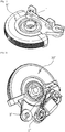
Fig. 1 is a perspective view showing the configuration of a prior art dial assembly, -
Fig. 2 is a perspective view showing the configuration of a prior art dial assembly, -
Fig. 3 is a perspective view showing the configuration of an air vent according to the present invention, -
Fig. 4 is a perspective view showing a coupling state of an air vent according to the present invention, -
Fig. 5 is a perspective view showing a coupling state of an air vent according to the present invention, -
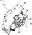
Fig. 6 is a perspective view showing a dial housing according to the present invention, -
Fig. 7 is a perspective view showing an operation state of a dial assembly according to the present invention, and -
Fig. 8 is a side view showing an operation state of the dial assembly according to the present invention. - Hereinafter, embodiments of the present invention will now be described with respect to the configuration in detail with reference to the accompanied drawings.
- An air vent dial for an automobile according to the present invention is derived to reduce parts cost and improve quality through the improvement of the click phase of the dial assembly.
- Referring to
Fig. 3 to Fig. 5 , adial knob 31 is assembled into the front surface portion of an automobile so as to be exposed, and adamper 11 is rotationally provided to an air path in anair vent housing 10 and opens or closes the air path by using thelink member 12 assembled into the rear portion of thedial knob 31. - The
dial assembly 30 including thedial knob 31 is coupled to thedial housing 20, and thedial housing 20 is assembled and fixed in theair vent housing 10 such that thedamper 11 rotates in association with the movement of thelink member 12 by the operation of thedial knob 31. - Now, explaining the above structure in more detail, the
air vent housing 10 is provided with the air path therein such that thedamper 11 is rotationally provided to the air path. - The
dial housing 20 is provided to theair vent housing 10 and has anopening 21 formed at the front portion thereof and holdingprojections 25 provided to the rear outer peripheral surface thereof. - In addition, the
dial assembly 30 is rotationally coupled to thedial housing 20 and has thedial knob 31 at the front portion thereof so as to be fitted into theopening 21 and exposed to the outside and arear fixing plate 32 of which one side is connected to thedamper 11 through thelink member 12 so as to control the opening and closing degrees of thedamper 11. - According to the present invention, by using the
dial assembly 30 and thedial housing 20 and by simply coupling these two parts, a user can recognize the click phase at the time of operating thedial knob 31, thereby reducing the number of required parts and man-hour. - First of all, referring to
Fig. 6 , thedial housing 20 has a housingelongated hole 24 in a rear body and theholding projections 25 respectively formed at positions corresponding to the opening and closing positions of the damper along the rear outer peripheral surface thereof. - That is, the
holding projections 25 are respectively formed to protrude from the rear outer peripheral surface thereof at positions corresponding to the opening and closing positions of thedamper 11 along the rear outer peripheral surface thereof. - Further, the
dial housing 20 is coupled and fixed to theair vent housing 10 and has theopening 21 formed in the front portion and a hole formed in the center portion so as to be coupled with thedial assembly 30. - In addition, referring to
Fig. 7 , thedial assembly 30 is rotationally coupled to thedial housing 20 in the center portion thereof and has thedial knob 31 provided to the front portion thereof and fitted into theopening 21 so as to be exposed to the outside, therear fixing plate 32 extending from the rear portion thereof and provided with anelongated hole 33 and thefixing projections 34 projecting inwards and coming into contact with theholding projections 25 while being guided and moving along the rear outer peripheral surface of thedial housing 20 at the outside of therear fixing plate 32 having the dialelongated hole 33. - Further, the
dial assembly 30 is coupled to one end of thelink member 12 connected to thedamper 11 at one side such that thelink member 12 moves in response to the rotation of thedial assembly 30 so as to control the opening and closing degrees of thedamper 11. - Meanwhile, the
holding projections 25 of dial housing 20 move with elastic force in the direction of the housingelongated hole 24. Further, thefixing projections 34 of thedial assembly 30 are formed on the outside of therear fixing plate 32 and has the dialelongated hole 33 in the inside direction of thefixing projections 34, such that the outside of therear fixing plate 32 provided with thefixing projections 34 is formed to have relatively small thickness and elasticity so as to move with elastic force in the outside direction. - Therefore, referring to
Fig. 8 , if thedial knob 31 is rotated in a state, in which thedial assembly 30 is coupled to thedial housing 20, thefixing projections 34 of the rear portion rotates along the outer peripheral surface of thedial housing 20 and come into contact with theholding projections 25 of the opening or closing positions. - At this time, if the
dial knob 31 is further rotated, thefixing projections 34 and theholding projections 25 are pushed by each other and thefixing projections 34 pass theholding projections 25. - That is, the holding
projections 25 of thedial housing 20 are pushed with the elastic force in the direction of the housing elongatedhole 24, and the fixingprojections 34 of thedial assembly 30 are pushed with the elastic force in the outside direction as thedial assembly 30 has therear fixing plate 32 which has the elastic force by the dial elongatedhole 33. - Therefore, in a state, in which the
dial knob 31 is further rotated such that the fixingprojections 34 which are pushed back by the elastic force pass the holdingprojections 25, the fixingprojections 34 and the holdingprojections 25 are restored to the initial states thereof and the user can feel the click phase. - Meanwhile, the
dial housing 20 and thedial assembly 30 are made from plastic materials and the fixingprojections 34 and the holdingprojections 25 have the elastic force by the housing elongatedhole 24 and the dial elongatedhole 33 such that no noise can be generated in the process of contact and deformation. - Therefore, selective fixing can be realized at a position desired by the user at the time of rotating the
dial knob 31 such that the user can control the air flow rate according to the opening and closing of thedamper 11. - Hereinafter, embodiments of the present invention structured as above will now be explained in more detail.
- First, if the user rotates the
dial knob 31 which is axially coupled to thedial housing 20, thelink member 12 assembled with therear fixing plate 32 of thedial knob 31 moves together therewith. - At this time, the other end of the
link member 12 is connected to thedamper 11 such that thedamper 11 in theair vent housing 10 rotates by the rotation of thedial knob 31 so as to open or close the air path. - In addition, the fixing
projections 34 are in a contact state with the body rear outer peripheral surface of thedial housing 20 and move along the body rear outer peripheral surface of thedial housing 20 in a state, in which thedial assembly 30 according to the present invention is coupled and fixed to thedial housing 20. - That is, the fixing
projections 34 rotate together with thedial knob 31 in a state, in which the fixingprojections 34 are in contact with the outer peripheral surface of thedial housing 20, and pass the holdingprojections 25 which are formed to project from the outer peripheral surface of thedial housing 20 at the position where thedamper 11 is closed. - At this time, the fixing
projections 34 and the holdingprojections 25 are formed to have the elastic force so as to come into contact with each other and be pushed back from each other. Therefore, the fixingprojections 34 pass the holdingprojections 25 and are restored. - Therefore, the user can recognize the click phase indicating that the
damper 11 is closed when rotating thedial knob 31 and can also recognize the click phase as the fixingprojections 34 pass the holdingprojections 25 even when thedamper 11 is opened by rotating thedial knob 31 in the opposite direction. - Herein, it is preferable that the holding
projections 25 of thedial housing 20 and the fixingprojections 34 of thedial assembly 30 are formed to be rounded such that the holdingprojections 25 can naturally pass the fixingprojections 34. - The embodiments described above are to be understood as a few illustrative examples of the present invention and the present invention is not limited to the embodiments and the drawings. It will be understood by those skilled in the art that various modifications, combinations and changes may be made to the embodiments without departing from the scope of the present invention.
-
- 10: Air vent housing 11: Damper
- 12: Link member 20: Dial housing
- 24: Housing elongated hole 25: Holding projections
- 30: Dial assembly 31: Dial knob
- 32: Rear fixing plate 33: Dial elongated hole
- 34: Fixing projections
Claims (2)
- An air vent dial for an automobile, comprising:an air vent housing (10) having an air path at an inside portion and a damper (11) rotationally provided at the air path so as to open or close the air path;a dial housing (20) provided in the air vent housing (10) and having an opening (21) formed at a front portion thereof; anda dial assembly (30) rotationally coupled to the dial housing (20) and having a dial knob (31) provided at a front portion of the dial assembly (30) so as to be fitted into the opening (21) and exposed to outside, and a rear fixing plate (32) connected to the damper (11) through a link member (12) to control opening and closing degrees of the damper (11), comprising a dial elongated hole (33) formed in the rear fixing plate (32),
characterized in that the dial housing (20) further comprisesa housing elongated hole (24) formed in a rear body, andholding projections (25) respectively formed at a rear outer peripheral surface corresponding to opening and closing positions of the damper (11) along a rear outer peripheral surface of the dial housing (20), andwherein the dial assembly (30) further comprises
fixing projections (34) projecting inwards and contacting the holding projections (25) while being guided and moving along the rear outer peripheral surface of the dial housing (20) outside the rear fixing plate (32). - An air vent dial for an automobile according to claim 1, wherein the holding projections (25) of the housing (20) move with an elastic force in a direction of the housing elongated hole (24), and
the fixing projections (34) of the dial assembly (30) move with an elastic force in an outside direction of the dial elongated hole (33).
Applications Claiming Priority (2)
| Application Number | Priority Date | Filing Date | Title |
|---|---|---|---|
| KR2020130009935U KR200474744Y1 (en) | 2013-12-02 | 2013-12-02 | Air vent for automobile |
| PCT/KR2014/011629 WO2015084001A1 (en) | 2013-12-02 | 2014-12-01 | Air vent dial for automobile |
Publications (3)
| Publication Number | Publication Date |
|---|---|
| EP3077237A1 EP3077237A1 (en) | 2016-10-12 |
| EP3077237A4 EP3077237A4 (en) | 2017-08-02 |
| EP3077237B1 true EP3077237B1 (en) | 2018-06-27 |
Family
ID=51999888
Family Applications (1)
| Application Number | Title | Priority Date | Filing Date |
|---|---|---|---|
| EP14867400.5A Active EP3077237B1 (en) | 2013-12-02 | 2014-12-01 | Air vent dial for automobile |
Country Status (6)
| Country | Link |
|---|---|
| US (1) | US9821631B2 (en) |
| EP (1) | EP3077237B1 (en) |
| JP (1) | JP6325101B2 (en) |
| KR (1) | KR200474744Y1 (en) |
| CN (1) | CN105793077B (en) |
| WO (1) | WO2015084001A1 (en) |
Cited By (1)
| Publication number | Priority date | Publication date | Assignee | Title |
|---|---|---|---|---|
| CN111731076A (en) * | 2020-07-06 | 2020-10-02 | 宁波均胜群英汽车系统股份有限公司 | Air guide mechanism and automobile air conditioner air outlet using same |
Families Citing this family (13)
| Publication number | Priority date | Publication date | Assignee | Title |
|---|---|---|---|---|
| JP6381900B2 (en) * | 2013-12-05 | 2018-08-29 | 三菱重工サーマルシステムズ株式会社 | Damper opening / closing mechanism for vehicle air conditioner |
| CN107366775B (en) * | 2016-05-13 | 2020-09-25 | 博格华纳公司 | Biasing apparatus for linkage system and methods of making and using same |
| EP3293026B1 (en) * | 2016-09-13 | 2020-07-22 | Ningbo Geely Automobile Research & Development Co., Ltd. | Air nozzle device for a vehicle |
| US10780765B2 (en) * | 2017-06-08 | 2020-09-22 | Ford Global Technologies, Llc | Low-friction ride plate for operating an airflow damper of a vehicle HVAC register and method of formation thereof |
| CN107139688B (en) * | 2017-07-03 | 2023-05-05 | 宁波福尔达智能科技股份有限公司 | Driving wheel structure for air outlet of automobile air conditioner |
| KR101977216B1 (en) * | 2017-07-06 | 2019-05-10 | 주식회사 니프코코리아 | Damper dial for automobile air vent |
| JP2019188845A (en) * | 2018-04-18 | 2019-10-31 | 豊田合成株式会社 | register |
| US11726179B2 (en) * | 2019-07-01 | 2023-08-15 | Pony Ai Inc. | System and method for regulating airflow into an enclosure |
| US11592529B2 (en) * | 2019-07-01 | 2023-02-28 | Pony Ai Inc. | System and method for reducing noise into an enclosure |
| CN112354173B (en) * | 2020-11-16 | 2022-09-23 | 维沃移动通信有限公司 | Electronic equipment and handle thereof |
| USD1087848S1 (en) | 2023-02-09 | 2025-08-12 | Aston Martin Lagonda Limited | Dashboard for automobile or replica thereof |
| USD1087852S1 (en) * | 2023-02-09 | 2025-08-12 | Aston Martin Lagonda Limited | Air vent for automobile or replica thereof |
| USD1110928S1 (en) | 2023-06-19 | 2026-02-03 | Aston Martin Lagonda Limited | Console for automobile or replica thereof |
Family Cites Families (24)
| Publication number | Priority date | Publication date | Assignee | Title |
|---|---|---|---|---|
| JPS61135712U (en) * | 1985-02-14 | 1986-08-23 | ||
| US4769626A (en) * | 1987-07-02 | 1988-09-06 | United Technologies Automotive, Inc. | Positive feel variable resistance switch |
| JPH089560Y2 (en) * | 1989-07-21 | 1996-03-21 | 日本プラスト株式会社 | Shutter valve opening / closing device for vehicle air conditioners |
| JPH0367850U (en) * | 1989-10-25 | 1991-07-03 | ||
| JP2564573Y2 (en) | 1991-08-26 | 1998-03-09 | 日本プラスト 株式会社 | Dial operation device for vehicle air conditioning |
| JP3019713B2 (en) * | 1994-02-21 | 2000-03-13 | 豊田合成株式会社 | Operation knob assembly structure |
| US6582293B1 (en) * | 1999-11-01 | 2003-06-24 | Andrew Siniarski | Air vent damper apparatus |
| FR2810949B1 (en) * | 2000-06-28 | 2002-10-31 | Ecia Equip Composants Ind Auto | DEFROSTING NOZZLE ASSEMBLY AND EQUIPMENT THEREOF |
| KR100613711B1 (en) * | 2004-09-15 | 2006-08-21 | 현대모비스 주식회사 | Air vent of vehicle |
| CA2484305A1 (en) * | 2004-10-08 | 2006-04-08 | Progressive Moulded Products Limited | Control wheel |
| KR100710669B1 (en) | 2005-10-10 | 2007-04-24 | 현대모비스 주식회사 | Ventilation control device for vehicle air vent |
| EP2046591A4 (en) * | 2006-07-27 | 2010-04-21 | Collins & Aikman Prod Co | Air vent providing diffusion |
| JP2008265595A (en) * | 2007-04-23 | 2008-11-06 | Valeo Thermal Systems Japan Corp | Air conditioner for automobile |
| DE102008014377A1 (en) * | 2008-03-17 | 2009-09-24 | Behr Gmbh & Co. Kg | Adjusting device for an air vent |
| KR20090120262A (en) * | 2008-05-19 | 2009-11-24 | 주식회사 니프코코리아 | Damper dial assembly structure of automobile air vent |
| KR20110021225A (en) * | 2009-08-25 | 2011-03-04 | 현대모비스 주식회사 | Air vent |
| KR200458759Y1 (en) * | 2009-11-05 | 2012-03-06 | 한국 티알더블류 자동차부품산업 주식회사 | Air vent for vechicle |
| KR20110071502A (en) * | 2009-12-21 | 2011-06-29 | 주식회사 니프코코리아 | Car air vent |
| KR101063724B1 (en) * | 2009-12-28 | 2011-09-07 | 주식회사 니프코코리아 | Car air vent |
| KR200462226Y1 (en) | 2011-04-27 | 2012-09-04 | 한국 티알더블류 자동차부품산업 주식회사 | Air vent for vechicle |
| GB2508338A (en) * | 2012-11-21 | 2014-06-04 | China Tool Projects Uk Ltd | Thumbwheel Control for a Rotary Actuator |
| US9110492B2 (en) * | 2013-04-30 | 2015-08-18 | Global Ip Holdings, Llc | Assembly having a soft-touch user interface for controlling the operative position of a device which controls the flow of air into the passenger compartment of a vehicle |
| KR101409532B1 (en) * | 2013-06-05 | 2014-06-19 | 주식회사 니프코코리아 | A dual damper apparatus for vehicle's air veht |
| KR102078983B1 (en) * | 2013-07-24 | 2020-02-19 | 현대모비스 주식회사 | Damper Unit and Air Vent of Vehicle using the same |
-
2013
- 2013-12-02 KR KR2020130009935U patent/KR200474744Y1/en not_active Expired - Fee Related
-
2014
- 2014-12-01 CN CN201480065782.5A patent/CN105793077B/en active Active
- 2014-12-01 JP JP2016528876A patent/JP6325101B2/en active Active
- 2014-12-01 WO PCT/KR2014/011629 patent/WO2015084001A1/en not_active Ceased
- 2014-12-01 US US15/038,526 patent/US9821631B2/en not_active Expired - Fee Related
- 2014-12-01 EP EP14867400.5A patent/EP3077237B1/en active Active
Non-Patent Citations (1)
| Title |
|---|
| None * |
Cited By (1)
| Publication number | Priority date | Publication date | Assignee | Title |
|---|---|---|---|---|
| CN111731076A (en) * | 2020-07-06 | 2020-10-02 | 宁波均胜群英汽车系统股份有限公司 | Air guide mechanism and automobile air conditioner air outlet using same |
Also Published As
| Publication number | Publication date |
|---|---|
| CN105793077A (en) | 2016-07-20 |
| JP2016538180A (en) | 2016-12-08 |
| KR200474744Y1 (en) | 2014-10-08 |
| JP6325101B2 (en) | 2018-05-16 |
| EP3077237A4 (en) | 2017-08-02 |
| US9821631B2 (en) | 2017-11-21 |
| EP3077237A1 (en) | 2016-10-12 |
| CN105793077B (en) | 2018-02-09 |
| WO2015084001A1 (en) | 2015-06-11 |
| US20160297279A1 (en) | 2016-10-13 |
Similar Documents
| Publication | Publication Date | Title |
|---|---|---|
| US9821631B2 (en) | Air vent dial for automobile | |
| EP3230098B1 (en) | Air vent for vehicle | |
| CN113266222A (en) | Scissor door hinge and vehicle | |
| EP3003752B1 (en) | Dual damper device of vehicle air vent | |
| CN102422047A (en) | Air damper | |
| CN112706586A (en) | Hidden air outlet | |
| JP4199230B2 (en) | Hinge structure of vehicle glove box | |
| CN107139688B (en) | Driving wheel structure for air outlet of automobile air conditioner | |
| JP6079655B2 (en) | Air conditioning register | |
| WO2015041445A1 (en) | Air vent dial for vehicle | |
| CN214775289U (en) | Hidden air outlet | |
| KR101652772B1 (en) | Hinge structure of armrest for a vehicle | |
| JP6842346B2 (en) | register | |
| KR20200046891A (en) | Covering structure of charging port for vehicle | |
| KR101866043B1 (en) | Door checker for vehicle | |
| KR200490350Y1 (en) | Portable device holder for vehicle | |
| JP2009047380A (en) | register | |
| JP3172742U (en) | register | |
| CN103270333B (en) | Automotive Air Damper | |
| JP4227709B2 (en) | Link mechanism lever structure | |
| JP5704991B2 (en) | register | |
| KR101566704B1 (en) | Glove box for vehicles | |
| KR20190076276A (en) | Bumper beam unit having air flap | |
| JP2007220275A (en) | Closure flap device | |
| JP5971957B2 (en) | Valve device |
Legal Events
| Date | Code | Title | Description |
|---|---|---|---|
| PUAI | Public reference made under article 153(3) epc to a published international application that has entered the european phase |
Free format text: ORIGINAL CODE: 0009012 |
|
| 17P | Request for examination filed |
Effective date: 20160607 |
|
| AK | Designated contracting states |
Kind code of ref document: A1 Designated state(s): AL AT BE BG CH CY CZ DE DK EE ES FI FR GB GR HR HU IE IS IT LI LT LU LV MC MK MT NL NO PL PT RO RS SE SI SK SM TR |
|
| AX | Request for extension of the european patent |
Extension state: BA ME |
|
| DAX | Request for extension of the european patent (deleted) | ||
| A4 | Supplementary search report drawn up and despatched |
Effective date: 20170704 |
|
| RIC1 | Information provided on ipc code assigned before grant |
Ipc: B60H 1/34 20060101ALI20170628BHEP Ipc: B60H 1/00 20060101AFI20170628BHEP |
|
| GRAP | Despatch of communication of intention to grant a patent |
Free format text: ORIGINAL CODE: EPIDOSNIGR1 |
|
| RIC1 | Information provided on ipc code assigned before grant |
Ipc: F16K 31/44 20060101ALI20180115BHEP Ipc: B60H 1/00 20060101AFI20180115BHEP Ipc: G05G 1/10 20060101ALI20180115BHEP Ipc: B60H 1/34 20060101ALI20180115BHEP Ipc: F16K 37/00 20060101ALI20180115BHEP |
|
| INTG | Intention to grant announced |
Effective date: 20180220 |
|
| RIN1 | Information on inventor provided before grant (corrected) |
Inventor name: KIM, JEONG HOON |
|
| GRAS | Grant fee paid |
Free format text: ORIGINAL CODE: EPIDOSNIGR3 |
|
| GRAJ | Information related to disapproval of communication of intention to grant by the applicant or resumption of examination proceedings by the epo deleted |
Free format text: ORIGINAL CODE: EPIDOSDIGR1 |
|
| GRAL | Information related to payment of fee for publishing/printing deleted |
Free format text: ORIGINAL CODE: EPIDOSDIGR3 |
|
| GRAR | Information related to intention to grant a patent recorded |
Free format text: ORIGINAL CODE: EPIDOSNIGR71 |
|
| GRAA | (expected) grant |
Free format text: ORIGINAL CODE: 0009210 |
|
| INTC | Intention to grant announced (deleted) | ||
| INTG | Intention to grant announced |
Effective date: 20180517 |
|
| AK | Designated contracting states |
Kind code of ref document: B1 Designated state(s): AL AT BE BG CH CY CZ DE DK EE ES FI FR GB GR HR HU IE IS IT LI LT LU LV MC MK MT NL NO PL PT RO RS SE SI SK SM TR |
|
| REG | Reference to a national code |
Ref country code: GB Ref legal event code: FG4D |
|
| REG | Reference to a national code |
Ref country code: AT Ref legal event code: REF Ref document number: 1011987 Country of ref document: AT Kind code of ref document: T Effective date: 20180715 |
|
| REG | Reference to a national code |
Ref country code: IE Ref legal event code: FG4D |
|
| REG | Reference to a national code |
Ref country code: DE Ref legal event code: R096 Ref document number: 602014027704 Country of ref document: DE |
|
| PG25 | Lapsed in a contracting state [announced via postgrant information from national office to epo] |
Ref country code: NO Free format text: LAPSE BECAUSE OF FAILURE TO SUBMIT A TRANSLATION OF THE DESCRIPTION OR TO PAY THE FEE WITHIN THE PRESCRIBED TIME-LIMIT Effective date: 20180927 Ref country code: LT Free format text: LAPSE BECAUSE OF FAILURE TO SUBMIT A TRANSLATION OF THE DESCRIPTION OR TO PAY THE FEE WITHIN THE PRESCRIBED TIME-LIMIT Effective date: 20180627 Ref country code: FI Free format text: LAPSE BECAUSE OF FAILURE TO SUBMIT A TRANSLATION OF THE DESCRIPTION OR TO PAY THE FEE WITHIN THE PRESCRIBED TIME-LIMIT Effective date: 20180627 Ref country code: BG Free format text: LAPSE BECAUSE OF FAILURE TO SUBMIT A TRANSLATION OF THE DESCRIPTION OR TO PAY THE FEE WITHIN THE PRESCRIBED TIME-LIMIT Effective date: 20180927 Ref country code: SE Free format text: LAPSE BECAUSE OF FAILURE TO SUBMIT A TRANSLATION OF THE DESCRIPTION OR TO PAY THE FEE WITHIN THE PRESCRIBED TIME-LIMIT Effective date: 20180627 |
|
| REG | Reference to a national code |
Ref country code: NL Ref legal event code: MP Effective date: 20180627 |
|
| REG | Reference to a national code |
Ref country code: LT Ref legal event code: MG4D |
|
| PG25 | Lapsed in a contracting state [announced via postgrant information from national office to epo] |
Ref country code: LV Free format text: LAPSE BECAUSE OF FAILURE TO SUBMIT A TRANSLATION OF THE DESCRIPTION OR TO PAY THE FEE WITHIN THE PRESCRIBED TIME-LIMIT Effective date: 20180627 Ref country code: HR Free format text: LAPSE BECAUSE OF FAILURE TO SUBMIT A TRANSLATION OF THE DESCRIPTION OR TO PAY THE FEE WITHIN THE PRESCRIBED TIME-LIMIT Effective date: 20180627 Ref country code: GR Free format text: LAPSE BECAUSE OF FAILURE TO SUBMIT A TRANSLATION OF THE DESCRIPTION OR TO PAY THE FEE WITHIN THE PRESCRIBED TIME-LIMIT Effective date: 20180928 Ref country code: RS Free format text: LAPSE BECAUSE OF FAILURE TO SUBMIT A TRANSLATION OF THE DESCRIPTION OR TO PAY THE FEE WITHIN THE PRESCRIBED TIME-LIMIT Effective date: 20180627 |
|
| REG | Reference to a national code |
Ref country code: AT Ref legal event code: MK05 Ref document number: 1011987 Country of ref document: AT Kind code of ref document: T Effective date: 20180627 |
|
| PG25 | Lapsed in a contracting state [announced via postgrant information from national office to epo] |
Ref country code: NL Free format text: LAPSE BECAUSE OF FAILURE TO SUBMIT A TRANSLATION OF THE DESCRIPTION OR TO PAY THE FEE WITHIN THE PRESCRIBED TIME-LIMIT Effective date: 20180627 |
|
| PG25 | Lapsed in a contracting state [announced via postgrant information from national office to epo] |
Ref country code: AT Free format text: LAPSE BECAUSE OF FAILURE TO SUBMIT A TRANSLATION OF THE DESCRIPTION OR TO PAY THE FEE WITHIN THE PRESCRIBED TIME-LIMIT Effective date: 20180627 Ref country code: IS Free format text: LAPSE BECAUSE OF FAILURE TO SUBMIT A TRANSLATION OF THE DESCRIPTION OR TO PAY THE FEE WITHIN THE PRESCRIBED TIME-LIMIT Effective date: 20181027 Ref country code: EE Free format text: LAPSE BECAUSE OF FAILURE TO SUBMIT A TRANSLATION OF THE DESCRIPTION OR TO PAY THE FEE WITHIN THE PRESCRIBED TIME-LIMIT Effective date: 20180627 Ref country code: PL Free format text: LAPSE BECAUSE OF FAILURE TO SUBMIT A TRANSLATION OF THE DESCRIPTION OR TO PAY THE FEE WITHIN THE PRESCRIBED TIME-LIMIT Effective date: 20180627 Ref country code: CZ Free format text: LAPSE BECAUSE OF FAILURE TO SUBMIT A TRANSLATION OF THE DESCRIPTION OR TO PAY THE FEE WITHIN THE PRESCRIBED TIME-LIMIT Effective date: 20180627 Ref country code: RO Free format text: LAPSE BECAUSE OF FAILURE TO SUBMIT A TRANSLATION OF THE DESCRIPTION OR TO PAY THE FEE WITHIN THE PRESCRIBED TIME-LIMIT Effective date: 20180627 Ref country code: SK Free format text: LAPSE BECAUSE OF FAILURE TO SUBMIT A TRANSLATION OF THE DESCRIPTION OR TO PAY THE FEE WITHIN THE PRESCRIBED TIME-LIMIT Effective date: 20180627 |
|
| PG25 | Lapsed in a contracting state [announced via postgrant information from national office to epo] |
Ref country code: ES Free format text: LAPSE BECAUSE OF FAILURE TO SUBMIT A TRANSLATION OF THE DESCRIPTION OR TO PAY THE FEE WITHIN THE PRESCRIBED TIME-LIMIT Effective date: 20180627 Ref country code: SM Free format text: LAPSE BECAUSE OF FAILURE TO SUBMIT A TRANSLATION OF THE DESCRIPTION OR TO PAY THE FEE WITHIN THE PRESCRIBED TIME-LIMIT Effective date: 20180627 Ref country code: IT Free format text: LAPSE BECAUSE OF FAILURE TO SUBMIT A TRANSLATION OF THE DESCRIPTION OR TO PAY THE FEE WITHIN THE PRESCRIBED TIME-LIMIT Effective date: 20180627 |
|
| REG | Reference to a national code |
Ref country code: DE Ref legal event code: R097 Ref document number: 602014027704 Country of ref document: DE |
|
| PLBE | No opposition filed within time limit |
Free format text: ORIGINAL CODE: 0009261 |
|
| STAA | Information on the status of an ep patent application or granted ep patent |
Free format text: STATUS: NO OPPOSITION FILED WITHIN TIME LIMIT |
|
| PG25 | Lapsed in a contracting state [announced via postgrant information from national office to epo] |
Ref country code: DK Free format text: LAPSE BECAUSE OF FAILURE TO SUBMIT A TRANSLATION OF THE DESCRIPTION OR TO PAY THE FEE WITHIN THE PRESCRIBED TIME-LIMIT Effective date: 20180627 |
|
| 26N | No opposition filed |
Effective date: 20190328 |
|
| REG | Reference to a national code |
Ref country code: CH Ref legal event code: PL |
|
| PG25 | Lapsed in a contracting state [announced via postgrant information from national office to epo] |
Ref country code: SI Free format text: LAPSE BECAUSE OF FAILURE TO SUBMIT A TRANSLATION OF THE DESCRIPTION OR TO PAY THE FEE WITHIN THE PRESCRIBED TIME-LIMIT Effective date: 20180627 Ref country code: LU Free format text: LAPSE BECAUSE OF NON-PAYMENT OF DUE FEES Effective date: 20181201 Ref country code: MC Free format text: LAPSE BECAUSE OF FAILURE TO SUBMIT A TRANSLATION OF THE DESCRIPTION OR TO PAY THE FEE WITHIN THE PRESCRIBED TIME-LIMIT Effective date: 20180627 |
|
| REG | Reference to a national code |
Ref country code: IE Ref legal event code: MM4A |
|
| REG | Reference to a national code |
Ref country code: BE Ref legal event code: MM Effective date: 20181231 |
|
| PG25 | Lapsed in a contracting state [announced via postgrant information from national office to epo] |
Ref country code: IE Free format text: LAPSE BECAUSE OF NON-PAYMENT OF DUE FEES Effective date: 20181201 |
|
| PG25 | Lapsed in a contracting state [announced via postgrant information from national office to epo] |
Ref country code: BE Free format text: LAPSE BECAUSE OF NON-PAYMENT OF DUE FEES Effective date: 20181231 Ref country code: AL Free format text: LAPSE BECAUSE OF FAILURE TO SUBMIT A TRANSLATION OF THE DESCRIPTION OR TO PAY THE FEE WITHIN THE PRESCRIBED TIME-LIMIT Effective date: 20180627 |
|
| PG25 | Lapsed in a contracting state [announced via postgrant information from national office to epo] |
Ref country code: LI Free format text: LAPSE BECAUSE OF NON-PAYMENT OF DUE FEES Effective date: 20181231 Ref country code: CH Free format text: LAPSE BECAUSE OF NON-PAYMENT OF DUE FEES Effective date: 20181231 |
|
| PG25 | Lapsed in a contracting state [announced via postgrant information from national office to epo] |
Ref country code: MT Free format text: LAPSE BECAUSE OF NON-PAYMENT OF DUE FEES Effective date: 20181201 |
|
| PG25 | Lapsed in a contracting state [announced via postgrant information from national office to epo] |
Ref country code: TR Free format text: LAPSE BECAUSE OF FAILURE TO SUBMIT A TRANSLATION OF THE DESCRIPTION OR TO PAY THE FEE WITHIN THE PRESCRIBED TIME-LIMIT Effective date: 20180627 |
|
| PGFP | Annual fee paid to national office [announced via postgrant information from national office to epo] |
Ref country code: GB Payment date: 20191129 Year of fee payment: 6 |
|
| PG25 | Lapsed in a contracting state [announced via postgrant information from national office to epo] |
Ref country code: PT Free format text: LAPSE BECAUSE OF FAILURE TO SUBMIT A TRANSLATION OF THE DESCRIPTION OR TO PAY THE FEE WITHIN THE PRESCRIBED TIME-LIMIT Effective date: 20180627 |
|
| PG25 | Lapsed in a contracting state [announced via postgrant information from national office to epo] |
Ref country code: MK Free format text: LAPSE BECAUSE OF NON-PAYMENT OF DUE FEES Effective date: 20180627 Ref country code: HU Free format text: LAPSE BECAUSE OF FAILURE TO SUBMIT A TRANSLATION OF THE DESCRIPTION OR TO PAY THE FEE WITHIN THE PRESCRIBED TIME-LIMIT; INVALID AB INITIO Effective date: 20141201 Ref country code: CY Free format text: LAPSE BECAUSE OF FAILURE TO SUBMIT A TRANSLATION OF THE DESCRIPTION OR TO PAY THE FEE WITHIN THE PRESCRIBED TIME-LIMIT Effective date: 20180627 |
|
| GBPC | Gb: european patent ceased through non-payment of renewal fee |
Effective date: 20201201 |
|
| PG25 | Lapsed in a contracting state [announced via postgrant information from national office to epo] |
Ref country code: GB Free format text: LAPSE BECAUSE OF NON-PAYMENT OF DUE FEES Effective date: 20201201 |
|
| PGFP | Annual fee paid to national office [announced via postgrant information from national office to epo] |
Ref country code: DE Payment date: 20251028 Year of fee payment: 12 |
|
| PGFP | Annual fee paid to national office [announced via postgrant information from national office to epo] |
Ref country code: FR Payment date: 20251110 Year of fee payment: 12 |