EP3077116B1 - Spring tightening device, jaw crusher, processing plant of mineral material and method for compressing or decompressing spring loading tie rod in jaw crusher - Google Patents
Spring tightening device, jaw crusher, processing plant of mineral material and method for compressing or decompressing spring loading tie rod in jaw crusher Download PDFInfo
- Publication number
- EP3077116B1 EP3077116B1 EP14820903.4A EP14820903A EP3077116B1 EP 3077116 B1 EP3077116 B1 EP 3077116B1 EP 14820903 A EP14820903 A EP 14820903A EP 3077116 B1 EP3077116 B1 EP 3077116B1
- Authority
- EP
- European Patent Office
- Prior art keywords
- spring
- support part
- tightening device
- support
- tie rod
- Prior art date
- Legal status (The legal status is an assumption and is not a legal conclusion. Google has not performed a legal analysis and makes no representation as to the accuracy of the status listed.)
- Active
Links
- 239000000463 material Substances 0.000 title claims description 17
- 229910052500 inorganic mineral Inorganic materials 0.000 title claims description 10
- 238000000034 method Methods 0.000 title claims description 10
- 239000011707 mineral Substances 0.000 title claims description 10
- 230000006835 compression Effects 0.000 claims description 7
- 238000007906 compression Methods 0.000 claims description 7
- 125000006850 spacer group Chemical group 0.000 claims description 5
- 230000001681 protective effect Effects 0.000 description 11
- 230000008901 benefit Effects 0.000 description 4
- 239000011435 rock Substances 0.000 description 3
- 230000006837 decompression Effects 0.000 description 2
- 230000009467 reduction Effects 0.000 description 2
- 229910000760 Hardened steel Inorganic materials 0.000 description 1
- 239000010426 asphalt Substances 0.000 description 1
- 238000009412 basement excavation Methods 0.000 description 1
- 239000011449 brick Substances 0.000 description 1
- 230000008859 change Effects 0.000 description 1
- 239000004567 concrete Substances 0.000 description 1
- 238000010276 construction Methods 0.000 description 1
- 239000004035 construction material Substances 0.000 description 1
- 230000003247 decreasing effect Effects 0.000 description 1
- 238000004880 explosion Methods 0.000 description 1
- 230000006872 improvement Effects 0.000 description 1
- 238000009434 installation Methods 0.000 description 1
- 230000008569 process Effects 0.000 description 1
- 239000004575 stone Substances 0.000 description 1
- 239000002699 waste material Substances 0.000 description 1
Images

Classifications
-
- B—PERFORMING OPERATIONS; TRANSPORTING
- B02—CRUSHING, PULVERISING, OR DISINTEGRATING; PREPARATORY TREATMENT OF GRAIN FOR MILLING
- B02C—CRUSHING, PULVERISING, OR DISINTEGRATING IN GENERAL; MILLING GRAIN
- B02C1/00—Crushing or disintegrating by reciprocating members
- B02C1/02—Jaw crushers or pulverisers
- B02C1/025—Jaw clearance or overload control
-
- B—PERFORMING OPERATIONS; TRANSPORTING
- B02—CRUSHING, PULVERISING, OR DISINTEGRATING; PREPARATORY TREATMENT OF GRAIN FOR MILLING
- B02C—CRUSHING, PULVERISING, OR DISINTEGRATING IN GENERAL; MILLING GRAIN
- B02C1/00—Crushing or disintegrating by reciprocating members
- B02C1/02—Jaw crushers or pulverisers
- B02C1/04—Jaw crushers or pulverisers with single-acting jaws
-
- B—PERFORMING OPERATIONS; TRANSPORTING
- B02—CRUSHING, PULVERISING, OR DISINTEGRATING; PREPARATORY TREATMENT OF GRAIN FOR MILLING
- B02C—CRUSHING, PULVERISING, OR DISINTEGRATING IN GENERAL; MILLING GRAIN
- B02C1/00—Crushing or disintegrating by reciprocating members
-
- B—PERFORMING OPERATIONS; TRANSPORTING
- B02—CRUSHING, PULVERISING, OR DISINTEGRATING; PREPARATORY TREATMENT OF GRAIN FOR MILLING
- B02C—CRUSHING, PULVERISING, OR DISINTEGRATING IN GENERAL; MILLING GRAIN
- B02C1/00—Crushing or disintegrating by reciprocating members
- B02C1/02—Jaw crushers or pulverisers
- B02C1/06—Jaw crushers or pulverisers with double-acting jaws
-
- F—MECHANICAL ENGINEERING; LIGHTING; HEATING; WEAPONS; BLASTING
- F16—ENGINEERING ELEMENTS AND UNITS; GENERAL MEASURES FOR PRODUCING AND MAINTAINING EFFECTIVE FUNCTIONING OF MACHINES OR INSTALLATIONS; THERMAL INSULATION IN GENERAL
- F16F—SPRINGS; SHOCK-ABSORBERS; MEANS FOR DAMPING VIBRATION
- F16F1/00—Springs
- F16F1/02—Springs made of steel or other material having low internal friction; Wound, torsion, leaf, cup, ring or the like springs, the material of the spring not being relevant
- F16F1/04—Wound springs
- F16F1/12—Attachments or mountings
- F16F1/121—Attachments or mountings adjustable, e.g. to modify spring characteristics
Definitions
- the invention is related to the tightening of a spring loading a tie rod in a jaw crusher of mineral material.
- Mineral material such as rock
- the rock can be extracted from the ground for crushing by means of either explosions or excavation.
- the rock may also be natural stone and gravel, or construction waste. Both mobile crushers and stationary crushing applications are used for crushing.
- the material to be crushed is fed with an excavator or wheel loader to a feed hopper of a crusher or crushing plant, from where the material to be crushed may fall into the throat of the crusher, or a feeder transfers the rock material towards the crusher.
- the mineral material to be crushed may also be recyclable material, such as concrete, bricks, or asphalt.
- Jaw crushers are suitable for, for example, rough crushing at quarries or crushing of construction material. According to the operating principle of the jaw crusher, crushing takes place against jaws, termed fixed and moving jaw.
- side plates of the jaw crusher's frame support an upper end of a pendulum through an eccentric.
- a rear part of the jaw crusher's frame is fastened between the side plates.
- the pendulum is supported by the rear part of the frame through a toggle plate.
- a tie rod is arranged between a lower part of the pendulum and the rear part of the frame; the tie rod is spring-loaded and pulls the pendulum backwards towards the toggle plate.
- the spring influencing the tie rod is tightened with a nut influencing the spring; the nut is moved along a thread formed in the tie rod. Tightening the spring is difficult and requires large force and tools.
- US 3 318 540 A discloses a method and apparatus for arranging perpendicular relationship between the tie rod, spring and its supporting seat for a particular adjustment of a jaw of a jaw crusher, see col. 1, lines 50 to 56.
- the spring is tightened in place by a nut and washer at a threaded end of the tie rod as shown by Fig. 1 above reference sign E.
- the purpose of the invention is to avoid or mitigate problems related to prior art and/or offer new technical alternatives.
- a method for compressing or decompressing a spring loading a tie rod in a jaw crusher; the tie rod is supported, at one location, by a pendulum of the jaw crusher and, at another location, by the jaw crusher's frame through the said spring; and the spring is installed at a first section of the spring against a first spring support fastened to the jaw crusher's frame, and at another section of the spring against a second spring support supported by the tie rod, in which method:
- the moving screws are rotated alternately.
- the movement of the support part farther away from the first spring support is prevented by the locking member fastened to the tie rod.
- a female thread to be fastened to a thread formed in the tie rod is arranged as the locking member of the support part.
- the said female thread is arranged in the support part or a separate locking part, such as a nut.
- a thread is arranged in the support part for each moving screw supported by the support part, or the support part supports a nut for each moving screw supported by the support part, and the moving screw is moved in the thread of the support part or the nut.
- a spacer plate is arranged between the second spring support and the at least two moving screws supported by the support part.
- a guide bushing fastened to the second spring support supports the second spring support in relation to the tie rod.
- the moving screws are rotated in a first direction for a distance required by the compression of the spring.
- the moving screw is rotated for that long that the compression required of the spring is produced.
- the moving screws have a sufficient moving distance in a front direction of the movement range for compressing the spring; after the support part is installed, the nut arranged as the locking member is rotated in the thread formed at an end of the tie rod until the compression of the spring starts.
- the moving screws are rotated in a second, opposite direction for a distance required by the decompression of the spring.
- the nut is rotated off the tie rod to release the spring.
- the diameter of the thread of the moving screw is smaller than the diameter of the thread of the locking member.
- the tie rod is arranged inside the first spring support, the spring, the second spring support, and the support part placed in succession.
- a spring tightening device for compressing and decompressing a spring loading a tie rod in a jaw crusher;
- the tightening device comprises a second spring support supportable by the spring; and
- the tightening device comprises a support part; at least two moving screws supported by the support part and arranged to influence the second spring support; and a locking member to support the support part by means of the tie rod; and the distance between the second spring support and the support part is arranged to be changeable by rotating the at least two moving screws supported by the support part.
- space is provided for the tie rod inside the second spring support and the support part placed in succession.
- the tightening device comprises a female thread as the locking member formed in the support part or a separate locking part such as a nut.
- the tightening device comprises threads for moving each moving screw supported by the support part in relation to the support part; the threads are arranged in the support part or a nut supported by the support part.
- the tightening device comprises a spacer plate between the second spring support and the at least two moving screws supported by the support part.
- the tightening device comprises a tie rod guide bushing fastened to the second spring support.
- two; or three; or four; or five moving screws are arranged in the support part.
- the diameter of the thread of the moving screw is smaller than the diameter of the thread of the locking member.
- the length of the moving screw is chosen so that the moving distance of the moving screw from a rear position to a front position causes the compression required of the spring.
- a jaw crusher that comprises:
- the jaw crusher comprises a spring tightening device according to some aspect or embodiment of the invention.
- a processing plant of mineral material comprises a jaw crusher according to some aspect or embodiment of the invention.
- the processing plant of mineral material is a mobile processing plant.
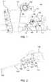
- FIG. 1 shows a jaw crusher 100 that comprises a fixed jaw 101 as a front part of the jaw crusher and a pendulum 102, preferably supported at its upper end by side plates 103 of the jaw crusher's frame through an eccentric 109.
- a rear part 108 of the jaw crusher's frame is fastened between the side plates.
- the pendulum is supported by the rear part of the frame through a toggle plate 104.
- a tie rod 105 is arranged between a lower end of the pendulum and the rear part 108 of the frame; the tie rod is loaded by a spring 107. When the spring 107 is tightened, the tie rod pulls the pendulum 102 backwards against the toggle plate 104.
- the spring influencing the tie rod is installed in place with a tightening device 110 according to a preferred embodiment of the invention.
- the jaw crusher comprises a protective structure 106 placed between the tightening device and the user.
- the protective structure comprises a protective plate fastened to the rear part 108.
- the protective structure is arranged to protect the user positioned behind the tightening device from uncontrollably moving objects from the direction of the tightening device.
- the protective structure 106 allows the user to manually use tools to compress and decompress the spring with the tightening device 110.
- Figure 2 shows a part of the jaw crusher in Figure 1 in a longitudinal cross section along the middle line of the tie rod 105.
- the spring 107 is positioned around the tie rod and compressed with the tightening device 110.
- the tie rod is supported at its first end 105' by the pendulum and at another location by a first spring support 122 supported by the rear part 108 of the jaw crusher's frame through the spring 107.
- the spring is installed at its first end 107' against the first spring support 122 fastened to the rear part of the frame.
- the spring tightening device 110 comprises a second spring support 112 installed against a second end 107" of the spring. The second spring support is supported by the tie rod and moved supported by the tie rod closer to the first spring support.
- Figure 3 shows a longitudinal cross section H-H of a tightening device 110 where the tightening device is in a spring compressing position.
- a second spring support 112 comprises a support surface 112' for the spring 107 on its first side.
- the tightening device comprises a support part 113 and at least two moving screws 114, 114' supported by the support part and arranged to influence the second spring support 112 from a second side opposite to the first side.
- the distance between the second spring support and the support part is arranged to be changeable by rotating the at least two moving screws supported by the support part, preferably alternately.
- the tightening device comprises threads for moving each moving screw supported by the support part 113 in relation to the support part; in the figure, the threads are arranged in a nut 115 supported by the support part 113.
- the nut is arranged to be non-rotatable in relation to the support part, whereby it suffices to use one tool to rotate the head of a moving screw to move the moving screw.
- the thread of the moving screw is integrated in the support part.
- a guide bushing 111 is fastened to the second spring support 112.
- the second spring support When the second spring support is supported by the tie rod through the guide bushing, the second spring support can be kept in a straight position against the spring 107.
- the tie rod can be protected against oil and/or dirt by means of the guide bushing.
- a through hole 117 such as a hole for the tie rod 105, is formed inside the second spring support 112 and the support part 113 placed in succession.
- a spacer plate 116 is arranged between the second spring support 112 and the moving screws.
- the spacer plate is made of wear-resistant material, such as hardened steel. This enables reducing the reshaping of material taking place at the contact points of the moving screws' ends.
- the tightening device comprises a locking member 120 to support the support part by means of the tie rod.
- a female thread to be fastened to a thread formed at an end of the tie rod 105 is arranged as the locking member 120.
- the locking member comprises a nut that is a locking part 121 separate from the support part 113.
- the locking member may be integrated in the support part, for example, a female thread formed in the support part.
- the locking member 120 fastened to the tie rod may be used to prevent the movement of the support part 113 father away from the first spring support 122.
- the spring compresses, i.e., contracts.
- the compression of the spring reduces, i.e., the spring decompresses.
- the tightening device 110 comprises a protective mantle 121 arranged to surround a space formed between the second spring support 112 and the support part 113 in the entire scope determined by the movement range of the moving screws.
- an additional feature is arranged in the protective mantle 121 through which the protective mantle 121 prevents the distance between the second spring support 112 and the support part from decreasing to a value smaller than desired when the tightening device is in a spring compressing position.
- the protective mantle is preferably fastened to the support part. During the tightening of the spring, the support part is preferably kept in place by means of the locking member.
- the protective mantle 121 is dimensioned so that the second spring support moves inside the protective mantle when the moving screws are used.
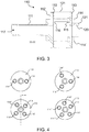
- Figure 4 shows alternative embodiments of the tightening device that include a varying number of tightening screws.
- An example according to Figure 3 is shown at lower left in Figure 4 , where four moving screws 114, 114', 114", 114''' can be used to change the distance between the second spring support and the support part.
- a tightening device is shown with two moving screws 114, 114" arranged in its support part 113.
- a tightening device is shown with three moving screws 114, 114", 114'” arranged in its support part 113.
- the tightening device is shown with five moving screws 114, 114', 114", 114"', 114"” arranged in its support part 113.
- other numbers greater than the two to five moving screws referred to in the examples meet the definition of at least two moving screws.
- the diameter of the thread of the moving screw 114-114"" is smaller than the diameter of the thread of the locking member 120 (the tie rod 105).
- the diameter of the thread of the tie rod is 48 mm.
- the diameter of the moving screw is 16 mm.
- the ratio between the diameters of the thread of the tie rod and the threads of the moving screws is 3.
- Figure 5 shows a phase of the tightening of the spring 107 where the tightening device 110 is at a rear position of the movement range.
- the spring is tightened, it is ensured that the moving screws 114-114"" have a sufficient moving distance to the front direction of the movement range to compress the spring.
- the second spring support and the support part are preferably close to each other, and the moving screws are preferably rotated almost open.
- the support part 113 is installed around the tie rod. After this, the nut arranged as the locking member 120 is rotated in the thread formed at the end of the tie rod 105 until the spring starts to compress.
- the pendulum In this phase, pulled by the tie rod, the pendulum is positioned against the toggle plate, which is positioned against the rear part 108 of the jaw crusher's frame.
- the ends of the spring 107', 107" are positioned against the spring supports 122,112.
- Figure 6 shows a phase of the tightening of the spring 107 where the tightening device is at the front position of the movement range.
- the moving screws have been rotated in the first direction for a distance required by the compression of the spring, preferably for the whole moving distance of the moving screws, in which case the spring 107 has contracted by the moving distance of the moving screws.
- the moving screws 114-114"" are rotated in a second, opposite direction (compared with the first direction) for a distance required by the decompression of the spring. After this, the nut can be rotated off the tie rod 105 to release the spring.
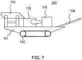
- Figure 7 shows a mobile processing plant of mineral material 200 that comprises a feeder 103 for feeding material to a jaw crusher 100 and a belt conveyor 106 for conveying the crushed product farther away from the processing plant.
- the jaw crusher comprises a tightening device 110 according to an embodiment of the invention.
- the processing plant 200 also comprises a power supply and a control center 105.
- the power supply may be a diesel or electric engine, for example, which provides energy for use by process units and hydraulic circuits.
- the feeder, crusher, power supply, and conveyor are fastened to a frame 101, which in this embodiment also comprises a track base 102 for moving the processing plant.
- the processing plant may also be entirely or partly wheel-mounted or movable by feet. Alternatively, it may be movable/towable by means of a truck or other external power supply. In addition to those mentioned above, the processing plant may also be a stationary processing plant.
- the improvement of occupational safety can be regarded as a technical advantage of the various embodiments of the invention.
- facilitation of work and ergonomics can be considered a technical advantage of the various embodiments of the invention.
- the reduction of the force needed for tightening can be considered a technical advantage of the various embodiments of the invention.
- installation forces are lower than previously.
- rotating smaller screws smaller and lighter tools can be used.
- the reduction of the space needed for using a tool can be considered a technical advantage of the various embodiments of the invention.
- a larger movement can be effected all at once by using a tool, such as a ratchet wrench or ring spanner.
Description
- The invention is related to the tightening of a spring loading a tie rod in a jaw crusher of mineral material.
- Mineral material, such as rock, can be extracted from the ground for crushing by means of either explosions or excavation. The rock may also be natural stone and gravel, or construction waste. Both mobile crushers and stationary crushing applications are used for crushing. The material to be crushed is fed with an excavator or wheel loader to a feed hopper of a crusher or crushing plant, from where the material to be crushed may fall into the throat of the crusher, or a feeder transfers the rock material towards the crusher. The mineral material to be crushed may also be recyclable material, such as concrete, bricks, or asphalt.
- Jaw crushers are suitable for, for example, rough crushing at quarries or crushing of construction material. According to the operating principle of the jaw crusher, crushing takes place against jaws, termed fixed and moving jaw.
- In a known jaw crusher, side plates of the jaw crusher's frame support an upper end of a pendulum through an eccentric. A rear part of the jaw crusher's frame is fastened between the side plates. Below the eccentric, the pendulum is supported by the rear part of the frame through a toggle plate. A tie rod is arranged between a lower part of the pendulum and the rear part of the frame; the tie rod is spring-loaded and pulls the pendulum backwards towards the toggle plate. The spring influencing the tie rod is tightened with a nut influencing the spring; the nut is moved along a thread formed in the tie rod. Tightening the spring is difficult and requires large force and tools.
-
US 3 318 540 A discloses a method and apparatus for arranging perpendicular relationship between the tie rod, spring and its supporting seat for a particular adjustment of a jaw of a jaw crusher, see col. 1, lines 50 to 56. As with the known jaw crusher described in the foregoing, the spring is tightened in place by a nut and washer at a threaded end of the tie rod as shown byFig. 1 above reference sign E. - The purpose of the invention is to avoid or mitigate problems related to prior art and/or offer new technical alternatives.
- According to a first aspect of the invention, a method is provided for compressing or decompressing a spring loading a tie rod in a jaw crusher; the tie rod is supported, at one location, by a pendulum of the jaw crusher and, at another location, by the jaw crusher's frame through the said spring; and the spring is installed at a first section of the spring against a first spring support fastened to the jaw crusher's frame, and at another section of the spring against a second spring support supported by the tie rod, in which method:
- the second spring support is moved in relation to the tie rod;
- the second spring support is influenced by a support part of a tightening device and at least two moving screws supported by the support part;
- the support part is supported by the tie rod through a locking member; and
- the distance between the second spring support and the support part is changed by rotating the at least two moving screws supported by the support part.
- Preferably, the moving screws are rotated alternately.
- Preferably, the movement of the support part farther away from the first spring support is prevented by the locking member fastened to the tie rod.
- Preferably, a female thread to be fastened to a thread formed in the tie rod is arranged as the locking member of the support part.
- Preferably, the said female thread is arranged in the support part or a separate locking part, such as a nut.
- Preferably, a thread is arranged in the support part for each moving screw supported by the support part, or the support part supports a nut for each moving screw supported by the support part, and the moving screw is moved in the thread of the support part or the nut.
- Preferably, a spacer plate is arranged between the second spring support and the at least two moving screws supported by the support part.
- Preferably, a guide bushing fastened to the second spring support supports the second spring support in relation to the tie rod.
- Preferably, when the spring is compressed, the moving screws are rotated in a first direction for a distance required by the compression of the spring.
- Preferably, the moving screw is rotated for that long that the compression required of the spring is produced.
- Preferably, when the spring is compressed, it is ensured that the moving screws have a sufficient moving distance in a front direction of the movement range for compressing the spring; after the support part is installed, the nut arranged as the locking member is rotated in the thread formed at an end of the tie rod until the compression of the spring starts.
- Preferably, when the spring is decompressed, the moving screws are rotated in a second, opposite direction for a distance required by the decompression of the spring. Preferably, the nut is rotated off the tie rod to release the spring.
- Preferably, the diameter of the thread of the moving screw is smaller than the diameter of the thread of the locking member.
- Preferably, the tie rod is arranged inside the first spring support, the spring, the second spring support, and the support part placed in succession.
- According to a second aspect of the invention, a spring tightening device is provided for compressing and decompressing a spring loading a tie rod in a jaw crusher; the tightening device comprises a second spring support supportable by the spring; and the tightening device comprises a support part; at least two moving screws supported by the support part and arranged to influence the second spring support; and a locking member to support the support part by means of the tie rod; and the distance between the second spring support and the support part is arranged to be changeable by rotating the at least two moving screws supported by the support part.
- Preferably, space is provided for the tie rod inside the second spring support and the support part placed in succession.
- Preferably, the tightening device comprises a female thread as the locking member formed in the support part or a separate locking part such as a nut.
- Preferably, the tightening device comprises threads for moving each moving screw supported by the support part in relation to the support part; the threads are arranged in the support part or a nut supported by the support part.
- Preferably, the tightening device comprises a spacer plate between the second spring support and the at least two moving screws supported by the support part.
- Preferably, the tightening device comprises a tie rod guide bushing fastened to the second spring support.
- Preferably, two; or three; or four; or five moving screws are arranged in the support part.
- Preferably, the diameter of the thread of the moving screw is smaller than the diameter of the thread of the locking member.
- Preferably, the length of the moving screw is chosen so that the moving distance of the moving screw from a rear position to a front position causes the compression required of the spring.
- According to a third aspect of the invention, a jaw crusher is provided that comprises:
- a pendulum;
- a toggle plate arranged to support the pendulum by means of the jaw crusher's frame;
- a tie rod;
- the tie rod being fastened between the pendulum and the jaw crusher's frame;
- a spring for loading the tie rod and pulling the pendulum with the tie rod against the toggle plate;
- a first spring support fastened to the jaw crusher's frame;
- the said spring being installed at a first section of the spring against the first spring support; and
- a tightening device that comprises:
- a second spring support against which a second section of the spring is installed, the tightening device comprising a support part;
- at least two moving screws supported by the support part and arranged to influence the second spring support; and
- a locking member to support the support part by means of the tie rod;
- and the distance between the second spring support and the support part is arranged to be changeable by rotating the at least two moving screws supported by the support part.
- Preferably, the jaw crusher comprises a spring tightening device according to some aspect or embodiment of the invention.
- According to a fourth aspect of the invention, a processing plant of mineral material is provided that comprises a jaw crusher according to some aspect or embodiment of the invention.
- Preferably, the processing plant of mineral material is a mobile processing plant.
- Various embodiments of the present invention will only be or have only been described in connection with one or some of the aspects of the invention. A person skilled in the art will appreciate that any embodiment of an aspect of the invention may be applied in the same aspect and other aspects alone or in combination with other embodiments.
- The invention will be described in the following by way of example with reference to the appended drawings.
- Figure 1
- shows a longitudinal cross-section of a jaw crusher in which a spring of a pendulum's tie rod is tightened with a tightening device according to the invention;
- Figure 2
- shows the spring of the tie rod compressed with the tightening device of
Figure 1 ; - Figure 3
- shows a tightening device according to a preferred embodiment of the invention in a tightened position;
- Figure 4
- shows alternative embodiments of the tightening device which include a varying number of tightening screws;
- Figure 5
- shows a phase of the tightening of the spring where the tightening device is at a rear position of the movement range;
- Figure 6
- shows a phase of the tightening of the spring where the tightening device is at a front position of the movement range;
- Figure 7
- shows a processing plant of mineral material according to the invention that preferably comprises the crusher in
Figure 1 . - In the following description, like references refer to similar parts. It should be noted that the figures are not to scale in all cases and that they mainly serve the purpose of illustrating embodiments of the invention.
-
Figure 1 shows ajaw crusher 100 that comprises a fixedjaw 101 as a front part of the jaw crusher and apendulum 102, preferably supported at its upper end byside plates 103 of the jaw crusher's frame through an eccentric 109. Arear part 108 of the jaw crusher's frame is fastened between the side plates. The pendulum is supported by the rear part of the frame through atoggle plate 104. In addition, atie rod 105 is arranged between a lower end of the pendulum and therear part 108 of the frame; the tie rod is loaded by aspring 107. When thespring 107 is tightened, the tie rod pulls thependulum 102 backwards against thetoggle plate 104. The spring influencing the tie rod is installed in place with atightening device 110 according to a preferred embodiment of the invention. The jaw crusher comprises aprotective structure 106 placed between the tightening device and the user. Preferably, the protective structure comprises a protective plate fastened to therear part 108. Preferably, the protective structure is arranged to protect the user positioned behind the tightening device from uncontrollably moving objects from the direction of the tightening device. Preferably. theprotective structure 106 allows the user to manually use tools to compress and decompress the spring with thetightening device 110. -
Figure 2 shows a part of the jaw crusher inFigure 1 in a longitudinal cross section along the middle line of thetie rod 105. Thespring 107 is positioned around the tie rod and compressed with thetightening device 110. The tie rod is supported at its first end 105' by the pendulum and at another location by afirst spring support 122 supported by therear part 108 of the jaw crusher's frame through thespring 107. The spring is installed at its first end 107' against thefirst spring support 122 fastened to the rear part of the frame. Thespring tightening device 110 comprises asecond spring support 112 installed against asecond end 107" of the spring. The second spring support is supported by the tie rod and moved supported by the tie rod closer to the first spring support. -
Figure 3 shows a longitudinal cross section H-H of atightening device 110 where the tightening device is in a spring compressing position. Asecond spring support 112 comprises a support surface 112' for thespring 107 on its first side. The tightening device comprises asupport part 113 and at least two movingscrews 114, 114' supported by the support part and arranged to influence thesecond spring support 112 from a second side opposite to the first side. The distance between the second spring support and the support part is arranged to be changeable by rotating the at least two moving screws supported by the support part, preferably alternately. - The tightening device comprises threads for moving each moving screw supported by the
support part 113 in relation to the support part; in the figure, the threads are arranged in anut 115 supported by thesupport part 113. Preferably, the nut is arranged to be non-rotatable in relation to the support part, whereby it suffices to use one tool to rotate the head of a moving screw to move the moving screw. Alternatively, the thread of the moving screw is integrated in the support part. - In some preferred embodiments of the
tightening device 110, aguide bushing 111 is fastened to thesecond spring support 112. When the second spring support is supported by the tie rod through the guide bushing, the second spring support can be kept in a straight position against thespring 107. In addition, the tie rod can be protected against oil and/or dirt by means of the guide bushing. - Preferably, a through
hole 117, such as a hole for thetie rod 105, is formed inside thesecond spring support 112 and thesupport part 113 placed in succession. - In some embodiments of the
tightening device 110, aspacer plate 116 is arranged between thesecond spring support 112 and the moving screws. Preferably, the spacer plate is made of wear-resistant material, such as hardened steel. This enables reducing the reshaping of material taking place at the contact points of the moving screws' ends. - The tightening device comprises a locking
member 120 to support the support part by means of the tie rod. Preferably, a female thread to be fastened to a thread formed at an end of thetie rod 105 is arranged as the lockingmember 120. InFigure 2 , the locking member comprises a nut that is a lockingpart 121 separate from thesupport part 113. Alternatively, the locking member may be integrated in the support part, for example, a female thread formed in the support part. - The locking
member 120 fastened to the tie rod may be used to prevent the movement of thesupport part 113 father away from thefirst spring support 122. When the second spring support moves farther away from the support part as a result of using the moving screws, the spring compresses, i.e., contracts. When the second spring support moves closer to the support part as a result of using the moving screws, the compression of the spring reduces, i.e., the spring decompresses. - Preferably, the
tightening device 110 comprises aprotective mantle 121 arranged to surround a space formed between thesecond spring support 112 and thesupport part 113 in the entire scope determined by the movement range of the moving screws. According to some preferred embodiments, an additional feature is arranged in theprotective mantle 121 through which theprotective mantle 121 prevents the distance between thesecond spring support 112 and the support part from decreasing to a value smaller than desired when the tightening device is in a spring compressing position. The protective mantle is preferably fastened to the support part. During the tightening of the spring, the support part is preferably kept in place by means of the locking member. Theprotective mantle 121 is dimensioned so that the second spring support moves inside the protective mantle when the moving screws are used. -
Figure 4 shows alternative embodiments of the tightening device that include a varying number of tightening screws. An example according toFigure 3 is shown at lower left inFigure 4 , where four movingscrews screws support part 113. At upper right, a tightening device is shown with three movingscrews support part 113. At lower right, the tightening device is shown with five movingscrews support part 113. Naturally, other numbers greater than the two to five moving screws referred to in the examples meet the definition of at least two moving screws. - Preferably, the diameter of the thread of the moving screw 114-114"" is smaller than the diameter of the thread of the locking member 120 (the tie rod 105). Preferably, the diameter of the thread of the tie rod is 48 mm. Preferably, the diameter of the moving screw is 16 mm. Preferably, the ratio between the diameters of the thread of the tie rod and the threads of the moving screws is 3.
-
Figure 5 shows a phase of the tightening of thespring 107 where thetightening device 110 is at a rear position of the movement range. When the spring is tightened, it is ensured that the moving screws 114-114"" have a sufficient moving distance to the front direction of the movement range to compress the spring. In such a case, the second spring support and the support part are preferably close to each other, and the moving screws are preferably rotated almost open. Thesupport part 113 is installed around the tie rod. After this, the nut arranged as the lockingmember 120 is rotated in the thread formed at the end of thetie rod 105 until the spring starts to compress. In this phase, pulled by the tie rod, the pendulum is positioned against the toggle plate, which is positioned against therear part 108 of the jaw crusher's frame. The ends of thespring 107', 107" are positioned against the spring supports 122,112. -
Figure 6 shows a phase of the tightening of thespring 107 where the tightening device is at the front position of the movement range. The moving screws have been rotated in the first direction for a distance required by the compression of the spring, preferably for the whole moving distance of the moving screws, in which case thespring 107 has contracted by the moving distance of the moving screws. - When the
spring 107 is being decompressed, for example, when dismantling the spring from its place, the moving screws 114-114"" are rotated in a second, opposite direction (compared with the first direction) for a distance required by the decompression of the spring. After this, the nut can be rotated off thetie rod 105 to release the spring. -
Figure 7 shows a mobile processing plant ofmineral material 200 that comprises afeeder 103 for feeding material to ajaw crusher 100 and abelt conveyor 106 for conveying the crushed product farther away from the processing plant. The jaw crusher comprises atightening device 110 according to an embodiment of the invention. Theprocessing plant 200 also comprises a power supply and acontrol center 105. The power supply may be a diesel or electric engine, for example, which provides energy for use by process units and hydraulic circuits. - The feeder, crusher, power supply, and conveyor are fastened to a
frame 101, which in this embodiment also comprises atrack base 102 for moving the processing plant. The processing plant may also be entirely or partly wheel-mounted or movable by feet. Alternatively, it may be movable/towable by means of a truck or other external power supply. In addition to those mentioned above, the processing plant may also be a stationary processing plant. - Without limiting the scope of protection, interpretation, or potential applications of the invention, the improvement of occupational safety can be regarded as a technical advantage of the various embodiments of the invention. Furthermore, facilitation of work and ergonomics can be considered a technical advantage of the various embodiments of the invention. Moreover, the reduction of the force needed for tightening can be considered a technical advantage of the various embodiments of the invention. When the tightening device is used, installation forces are lower than previously. When rotating smaller screws, smaller and lighter tools can be used. Furthermore, the reduction of the space needed for using a tool can be considered a technical advantage of the various embodiments of the invention. In practice, a larger movement can be effected all at once by using a tool, such as a ratchet wrench or ring spanner.
- The description presented in the foregoing provides non-limiting examples of some embodiments of the invention. However, it is apparent to those skilled in the art that the invention is not limited to the details presented above, but that the invention may also be implemented in other equivalent ways.
- Some features of the embodiments presented may be utilized without employing other features. The above description must be regarded as an explanatory account describing the principles of the invention and not as limiting the invention. Thus the scope of the invention is only limited by the appended claims.
Claims (15)
- A method for compressing or decompressing a spring (107) loading a tie rod (105) in a jaw crusher (100); which tie rod is supported, at one location, by a pendulum (102) of the jaw crusher and, at another location, by the jaw crusher's frame (108) through the said spring; and the spring being installed at a first section (107') of the spring against a first spring support (122) fastened to the jaw crusher's frame, and at another section (107") of the spring against a second spring support (112) supported by the tie rod; whereinthe second spring support is moved in relation to the tie rod; characterized by:arranging the second spring support (112) to be influenced by a support part (113) of a tightening device (110) and at least two moving screws (114-114"") supported by the support part;supporting the support part by the tie rod (105) through a locking member (120); androtating the at least two moving screws supported by the support part for changing the distance between the second spring support and the support part.
- The method according to claim 1, characterized by preventing the movement of the support part (113) farther away from the first spring support (122) by the locking member (120) fastened to the tie rod (105).
- The method according to claim 1, characterized by arranging a female thread to be fastened to a thread formed in the tie rod (105) as the locking member (120) of the support part (113).
- The method according to claim 3, characterized by arranging said female thread in the support part or a separate locking part (121).
- The method according to any one of claims 1-4, characterized by arranging a thread for each screw (114-114"") supported by the support part in the support part (113), or supporting by the support part a nut (115) for each moving screw (114-114"") supported by the support part, and moving the moving screw in the thread of the support part or nut.
- A spring tightening device (110) for compressing and decompressing a spring (107) loading a tie rod (105) in a jaw crusher (100), which tightening device comprises a second spring support (112) supportable by the spring; characterized in that the tightening device (110) comprises:a support part (113);at least two moving screws (114-114"") supported by the support part and arranged to influence the second spring support (112); anda locking member (120) for supporting the support part by the tie rod (105);and that the distance between the second spring support and the support part is arranged to be changeable by rotating the at least two moving screws supported by the support part.
- The spring tightening device according to claim 6, characterized in that the tightening device comprises as the locking member (120) a female thread formed in the support part (113) or a separate locking part (121).
- The tightening device according to claim 6 or 7, characterized in that the tightening device comprises threads for moving each moving screw (114-114"") supported by the support part in relation to the support part, which threads are arranged in the support part (113) or a nut (115) supported by the support part.
- The spring tightening device according to any one of claims 6 to 8, characterized in that the tightening device comprises a spacer plate (116) between the second spring support (112) and the at least two moving screws (114-114"") supported by the support part.
- The spring tightening device according to any one of claims 6 to 9, characterized in that the tightening device comprises a tie rod guide bushing (111) fastened to the second spring support (112).
- The spring tightening device according to any one of claims 6 to 10, characterized in that two; or three; or four; or five moving screws (114-114"") are arranged in the support part (113).
- The spring tightening device according to claim 7, characterized in that the diameter of the thread of the moving screw (114-114"") is smaller than the diameter of the thread of the locking member (120).
- The spring tightening device according to any one of claims 6 to 12, characterized in that the length of the moving screw (114-114"") is chosen so that the moving distance of the moving screw from a rear position to a front position causes the compression required of the spring (107).
- Ajaw crusher (100) that comprises:a pendulum (102);a toggle plate (104), the pendulum being supported to a frame of the crusher through the toggle plate;a tie rod (105) fastened between the pendulum and the frame (108) of the jaw crusher;a spring (107) for loading the tie rod and pulling the pendulum with the tie rod against the toggle plate;a first spring support (122) fastened to the jaw crusher's frame (108);the said spring (107) being installed at a first section (107') of the spring against the first spring support (122); anda tightening device (110) comprising a second spring support (112) against which a second section (107") of the spring is installed, characterized in that the tightening device (110) is a spring tightening device according to any one of claims 6 to 19.
- A processing plant of mineral material (200), characterized in that the processing plant of mineral material comprises a jaw crusher (100) according to claim 14.
Applications Claiming Priority (2)
| Application Number | Priority Date | Filing Date | Title |
|---|---|---|---|
| FI20136228A FI125062B (en) | 2013-12-05 | 2013-12-05 | Spring clamping device, jaw crusher, plant for processing mineral materials and method for compressing and decompressing a spring which loads a return bar in a jaw crusher |
| PCT/FI2014/050928 WO2015082764A1 (en) | 2013-12-05 | 2014-11-28 | Spring tightening device, jaw crusher, processing plant of mineral material and method for compressing or decompressing spring loading tie rod in jaw crusher |
Publications (2)
| Publication Number | Publication Date |
|---|---|
| EP3077116A1 EP3077116A1 (en) | 2016-10-12 |
| EP3077116B1 true EP3077116B1 (en) | 2018-01-03 |
Family
ID=52232214
Family Applications (1)
| Application Number | Title | Priority Date | Filing Date |
|---|---|---|---|
| EP14820903.4A Active EP3077116B1 (en) | 2013-12-05 | 2014-11-28 | Spring tightening device, jaw crusher, processing plant of mineral material and method for compressing or decompressing spring loading tie rod in jaw crusher |
Country Status (9)
| Country | Link |
|---|---|
| US (1) | US10710086B2 (en) |
| EP (1) | EP3077116B1 (en) |
| JP (1) | JP6513672B2 (en) |
| CN (1) | CN105813756B (en) |
| AU (1) | AU2014359037B2 (en) |
| BR (1) | BR112016012619B1 (en) |
| FI (1) | FI125062B (en) |
| RU (1) | RU2664831C1 (en) |
| WO (1) | WO2015082764A1 (en) |
Families Citing this family (8)
| Publication number | Priority date | Publication date | Assignee | Title |
|---|---|---|---|---|
| DE102017108576B4 (en) * | 2017-04-21 | 2019-02-07 | Z & J Technologies Gmbh | Knife gate valve, fixing element and method for mounting a gate valve |
| CN107413422B (en) * | 2017-05-11 | 2023-04-18 | 能诚集团有限公司 | Jaw crusher with synchronous crushing and screening functions |
| GB2570451B (en) * | 2018-01-24 | 2021-12-29 | Terex Gb Ltd | Service platform and jaw crushing assembly including same |
| USD872141S1 (en) * | 2018-08-10 | 2020-01-07 | Superior Industries, Inc. | Jaw crusher forward wall |
| CN110369016B (en) * | 2019-07-05 | 2020-12-11 | 江西乐电易联科技有限公司 | Scrap fuse tube second grade crushing equipment |
| CN112705299B (en) * | 2021-01-29 | 2022-06-07 | 宁阳辰信建材有限公司 | Outdoor mine crusher for building stone processing and assembling and using method |
| CN113457768B (en) * | 2021-07-29 | 2022-09-30 | 铜陵丰泽建材科技有限公司 | Jaw crusher for tailing ore processing |
| CN114247544A (en) * | 2022-01-28 | 2022-03-29 | 玉林师范学院 | Bone crushing machine device |
Family Cites Families (28)
| Publication number | Priority date | Publication date | Assignee | Title |
|---|---|---|---|---|
| US1491430A (en) * | 1922-06-09 | 1924-04-22 | Albert H Stebbins | Crusher |
| US1972096A (en) * | 1930-12-06 | 1934-09-04 | Mary E Guest | Yielding jaw crushing machine |
| US2131801A (en) * | 1934-05-19 | 1938-10-04 | Nordberg Manufacturing Co | Double acting jaw crusher |
| US2532678A (en) * | 1947-03-31 | 1950-12-05 | Gruendler Crusher & Pulverizer | Toggle block adjusting device for jaw crushers |
| US2598942A (en) * | 1949-12-19 | 1952-06-03 | Smith Engineering Works | Jaw crusher with side thrust absorbing bearings |
| US2921750A (en) * | 1953-11-18 | 1960-01-19 | Picalarga Marcello | Stonebreaking machines |
| US3153512A (en) * | 1963-02-27 | 1964-10-20 | Allis Chalmers Mfg Co | Jaw crusher |
| US3318540A (en) * | 1964-12-16 | 1967-05-09 | Poor & Company Inc | Jaw crusher |
| FI53401C (en) | 1976-08-25 | 1978-05-10 | Rauma Repola Oy | SAETTING OVER ANORDING FOR ADJUSTMENT AV INSTALLATION IN THE FRAMEWORK |
| JPS5724011Y2 (en) * | 1976-09-09 | 1982-05-25 | ||
| FR2374957A1 (en) * | 1976-12-24 | 1978-07-21 | Fives Cail Babcock | JAW CRUSHER |
| JPS5915029B2 (en) | 1982-04-01 | 1984-04-07 | 株式会社中央機工 | Rotary cutter device in crusher |
| JPS6031783Y2 (en) * | 1982-05-14 | 1985-09-24 | 株式会社栗本鉄工所 | Joyo Classia tensioning device |
| JPS5933473Y2 (en) * | 1982-10-19 | 1984-09-18 | 株式会社神戸製鋼所 | Adjustment device for tension rod spring for jaw crusher |
| CA1202013A (en) * | 1982-07-15 | 1986-03-18 | Tsuyoshi Tanaka | Crusher |
| RU2043786C1 (en) * | 1991-09-30 | 1995-09-20 | Акционерное общество "Дробмаш" | Jaw crusher |
| US5799888A (en) * | 1996-03-25 | 1998-09-01 | Kabushiki Kaisha Kobe Seiko Sho | Jaw crusher |
| US6116530A (en) * | 1999-06-21 | 2000-09-12 | E & E Seegmiller Limited | Adapter for rock crusher |
| JP2003211014A (en) * | 2002-01-22 | 2003-07-29 | Niho Shoji:Kk | Apparatus for fixing and outer periphery pressurization of shaft of insert type crusher cutter |
| US7344097B2 (en) * | 2005-03-14 | 2008-03-18 | Cedarapids, Inc. | Jaw-type rock crusher with toggle plate tension bar |
| RU51527U1 (en) * | 2005-08-25 | 2006-02-27 | Георгий Игоревич Богачев | JACK CRUSH RETURN MECHANISM |
| US7708218B2 (en) * | 2005-08-29 | 2010-05-04 | Komatsu Ltd. | Jaw crusher and self-traveling crusher |
| ES2302445B1 (en) * | 2006-10-06 | 2009-05-05 | Suspensiones Elasticas Del Norte S.L. | NEW VIBRATION LEVELING AND AMORTIGUATION SYSTEM. |
| CN201361560Y (en) * | 2009-02-20 | 2009-12-16 | 上海世邦机器有限公司 | Tension device of jaw crusher |
| CN202146795U (en) * | 2011-06-30 | 2012-02-22 | 湖南三德科技发展有限公司 | Jaw crusher |
| EP2564928B1 (en) * | 2011-09-05 | 2013-11-13 | Sandvik Intellectual Property AB | Jaw crusher |
| CN103008045A (en) * | 2013-01-18 | 2013-04-03 | 贵州成智重工科技有限公司 | Tie rod spring mechanism of jaw crusher |
| FI125063B (en) * | 2013-12-05 | 2015-05-15 | Metso Minerals Inc | Clamping element, clamping device, jaw crusher, plant for processing mineral materials and method for adjusting the tension of a wear part |
-
2013
- 2013-12-05 FI FI20136228A patent/FI125062B/en active IP Right Grant
-
2014
- 2014-11-28 AU AU2014359037A patent/AU2014359037B2/en active Active
- 2014-11-28 JP JP2016535238A patent/JP6513672B2/en active Active
- 2014-11-28 EP EP14820903.4A patent/EP3077116B1/en active Active
- 2014-11-28 US US15/100,848 patent/US10710086B2/en active Active
- 2014-11-28 RU RU2016123328A patent/RU2664831C1/en active
- 2014-11-28 CN CN201480066537.6A patent/CN105813756B/en active Active
- 2014-11-28 WO PCT/FI2014/050928 patent/WO2015082764A1/en active Application Filing
- 2014-11-28 BR BR112016012619-0A patent/BR112016012619B1/en active IP Right Grant
Also Published As
| Publication number | Publication date |
|---|---|
| BR112016012619A2 (en) | 2017-08-08 |
| JP6513672B2 (en) | 2019-05-15 |
| CN105813756A (en) | 2016-07-27 |
| US20160303570A1 (en) | 2016-10-20 |
| EP3077116A1 (en) | 2016-10-12 |
| AU2014359037A1 (en) | 2016-07-07 |
| US10710086B2 (en) | 2020-07-14 |
| BR112016012619B1 (en) | 2022-06-14 |
| AU2014359037B2 (en) | 2017-11-02 |
| FI20136228A (en) | 2015-05-15 |
| CN105813756B (en) | 2018-08-10 |
| WO2015082764A1 (en) | 2015-06-11 |
| JP2016538997A (en) | 2016-12-15 |
| RU2664831C1 (en) | 2018-08-23 |
| FI125062B (en) | 2015-05-15 |
Similar Documents
| Publication | Publication Date | Title |
|---|---|---|
| EP3077116B1 (en) | Spring tightening device, jaw crusher, processing plant of mineral material and method for compressing or decompressing spring loading tie rod in jaw crusher | |
| EP3077117B1 (en) | Tightening member, tightening device, jaw crusher, processing plant of mineral material and method for adjusting tightness of wear part | |
| EP3122462B1 (en) | A jaw crusher, a crushing plant, and a method for using a jaw crusher | |
| AU2013339604B2 (en) | Eccentric roller crusher | |
| CN104411409A (en) | Apparatus and method for a crusher with an inverted cylinder | |
| Han et al. | Comparison of low-grade hematite product characteristics in a high-pressure grinding roller and jaw crusher | |
| AU2013405447A1 (en) | Jaw crusher, crushing plant and crushing method | |
| RU2503730C1 (en) | Concrete recycling plant | |
| WO2008125831A1 (en) | A crushing arrangement with pre-crushing device | |
| AU2008202666A1 (en) | Improved jaw crusher bucket | |
| KR101821059B1 (en) | Structure for supporting the repulsive force caused by hydraulic breaker and, small hydraulic breaking equipment having the same | |
| Aziz et al. | The effect of resin thickness on bolt-grout-concrete interaction in shear | |
| CN212820084U (en) | Fixing structure of cone crusher rolling mortar wall | |
| AT525972B1 (en) | PROCESSING DEVICE | |
| KR102535654B1 (en) | Building waste automatic treatment apparatus | |
| CN107899671A (en) | One kind finishing uses lime block quick crashing device | |
| US8425116B2 (en) | Split guide bushing for vertical pulverizers | |
| Kleinhans | Jaws primary gyratory: communution | |
| Wetter et al. | Crushing solutions for rom sizing | |
| ZA200607077B (en) | Roll crusher |
Legal Events
| Date | Code | Title | Description |
|---|---|---|---|
| PUAI | Public reference made under article 153(3) epc to a published international application that has entered the european phase |
Free format text: ORIGINAL CODE: 0009012 |
|
| 17P | Request for examination filed |
Effective date: 20160606 |
|
| AK | Designated contracting states |
Kind code of ref document: A1 Designated state(s): AL AT BE BG CH CY CZ DE DK EE ES FI FR GB GR HR HU IE IS IT LI LT LU LV MC MK MT NL NO PL PT RO RS SE SI SK SM TR |
|
| AX | Request for extension of the european patent |
Extension state: BA ME |
|
| DAX | Request for extension of the european patent (deleted) | ||
| RAP1 | Party data changed (applicant data changed or rights of an application transferred) |
Owner name: METSO MINERALS, INC. |
|
| GRAP | Despatch of communication of intention to grant a patent |
Free format text: ORIGINAL CODE: EPIDOSNIGR1 |
|
| INTG | Intention to grant announced |
Effective date: 20170619 |
|
| GRAS | Grant fee paid |
Free format text: ORIGINAL CODE: EPIDOSNIGR3 |
|
| GRAJ | Information related to disapproval of communication of intention to grant by the applicant or resumption of examination proceedings by the epo deleted |
Free format text: ORIGINAL CODE: EPIDOSDIGR1 |
|
| GRAL | Information related to payment of fee for publishing/printing deleted |
Free format text: ORIGINAL CODE: EPIDOSDIGR3 |
|
| GRAR | Information related to intention to grant a patent recorded |
Free format text: ORIGINAL CODE: EPIDOSNIGR71 |
|
| INTC | Intention to grant announced (deleted) | ||
| GRAA | (expected) grant |
Free format text: ORIGINAL CODE: 0009210 |
|
| INTG | Intention to grant announced |
Effective date: 20171106 |
|
| AK | Designated contracting states |
Kind code of ref document: B1 Designated state(s): AL AT BE BG CH CY CZ DE DK EE ES FI FR GB GR HR HU IE IS IT LI LT LU LV MC MK MT NL NO PL PT RO RS SE SI SK SM TR |
|
| REG | Reference to a national code |
Ref country code: GB Ref legal event code: FG4D |
|
| REG | Reference to a national code |
Ref country code: CH Ref legal event code: EP Ref country code: AT Ref legal event code: REF Ref document number: 959728 Country of ref document: AT Kind code of ref document: T Effective date: 20180115 |
|
| REG | Reference to a national code |
Ref country code: IE Ref legal event code: FG4D |
|
| REG | Reference to a national code |
Ref country code: DE Ref legal event code: R096 Ref document number: 602014019541 Country of ref document: DE |
|
| REG | Reference to a national code |
Ref country code: SE Ref legal event code: TRGR |
|
| REG | Reference to a national code |
Ref country code: NL Ref legal event code: MP Effective date: 20180103 |
|
| REG | Reference to a national code |
Ref country code: LT Ref legal event code: MG4D |
|
| REG | Reference to a national code |
Ref country code: AT Ref legal event code: MK05 Ref document number: 959728 Country of ref document: AT Kind code of ref document: T Effective date: 20180103 |
|
| PG25 | Lapsed in a contracting state [announced via postgrant information from national office to epo] |
Ref country code: NL Free format text: LAPSE BECAUSE OF FAILURE TO SUBMIT A TRANSLATION OF THE DESCRIPTION OR TO PAY THE FEE WITHIN THE PRESCRIBED TIME-LIMIT Effective date: 20180103 |
|
| PG25 | Lapsed in a contracting state [announced via postgrant information from national office to epo] |
Ref country code: HR Free format text: LAPSE BECAUSE OF FAILURE TO SUBMIT A TRANSLATION OF THE DESCRIPTION OR TO PAY THE FEE WITHIN THE PRESCRIBED TIME-LIMIT Effective date: 20180103 Ref country code: LT Free format text: LAPSE BECAUSE OF FAILURE TO SUBMIT A TRANSLATION OF THE DESCRIPTION OR TO PAY THE FEE WITHIN THE PRESCRIBED TIME-LIMIT Effective date: 20180103 Ref country code: ES Free format text: LAPSE BECAUSE OF FAILURE TO SUBMIT A TRANSLATION OF THE DESCRIPTION OR TO PAY THE FEE WITHIN THE PRESCRIBED TIME-LIMIT Effective date: 20180103 Ref country code: CY Free format text: LAPSE BECAUSE OF FAILURE TO SUBMIT A TRANSLATION OF THE DESCRIPTION OR TO PAY THE FEE WITHIN THE PRESCRIBED TIME-LIMIT Effective date: 20180103 Ref country code: NO Free format text: LAPSE BECAUSE OF FAILURE TO SUBMIT A TRANSLATION OF THE DESCRIPTION OR TO PAY THE FEE WITHIN THE PRESCRIBED TIME-LIMIT Effective date: 20180403 |
|
| PG25 | Lapsed in a contracting state [announced via postgrant information from national office to epo] |
Ref country code: IS Free format text: LAPSE BECAUSE OF FAILURE TO SUBMIT A TRANSLATION OF THE DESCRIPTION OR TO PAY THE FEE WITHIN THE PRESCRIBED TIME-LIMIT Effective date: 20180503 Ref country code: GR Free format text: LAPSE BECAUSE OF FAILURE TO SUBMIT A TRANSLATION OF THE DESCRIPTION OR TO PAY THE FEE WITHIN THE PRESCRIBED TIME-LIMIT Effective date: 20180404 Ref country code: PL Free format text: LAPSE BECAUSE OF FAILURE TO SUBMIT A TRANSLATION OF THE DESCRIPTION OR TO PAY THE FEE WITHIN THE PRESCRIBED TIME-LIMIT Effective date: 20180103 Ref country code: LV Free format text: LAPSE BECAUSE OF FAILURE TO SUBMIT A TRANSLATION OF THE DESCRIPTION OR TO PAY THE FEE WITHIN THE PRESCRIBED TIME-LIMIT Effective date: 20180103 Ref country code: AT Free format text: LAPSE BECAUSE OF FAILURE TO SUBMIT A TRANSLATION OF THE DESCRIPTION OR TO PAY THE FEE WITHIN THE PRESCRIBED TIME-LIMIT Effective date: 20180103 Ref country code: RS Free format text: LAPSE BECAUSE OF FAILURE TO SUBMIT A TRANSLATION OF THE DESCRIPTION OR TO PAY THE FEE WITHIN THE PRESCRIBED TIME-LIMIT Effective date: 20180103 Ref country code: BG Free format text: LAPSE BECAUSE OF FAILURE TO SUBMIT A TRANSLATION OF THE DESCRIPTION OR TO PAY THE FEE WITHIN THE PRESCRIBED TIME-LIMIT Effective date: 20180403 |
|
| REG | Reference to a national code |
Ref country code: DE Ref legal event code: R097 Ref document number: 602014019541 Country of ref document: DE |
|
| PG25 | Lapsed in a contracting state [announced via postgrant information from national office to epo] |
Ref country code: RO Free format text: LAPSE BECAUSE OF FAILURE TO SUBMIT A TRANSLATION OF THE DESCRIPTION OR TO PAY THE FEE WITHIN THE PRESCRIBED TIME-LIMIT Effective date: 20180103 Ref country code: IT Free format text: LAPSE BECAUSE OF FAILURE TO SUBMIT A TRANSLATION OF THE DESCRIPTION OR TO PAY THE FEE WITHIN THE PRESCRIBED TIME-LIMIT Effective date: 20180103 Ref country code: AL Free format text: LAPSE BECAUSE OF FAILURE TO SUBMIT A TRANSLATION OF THE DESCRIPTION OR TO PAY THE FEE WITHIN THE PRESCRIBED TIME-LIMIT Effective date: 20180103 Ref country code: EE Free format text: LAPSE BECAUSE OF FAILURE TO SUBMIT A TRANSLATION OF THE DESCRIPTION OR TO PAY THE FEE WITHIN THE PRESCRIBED TIME-LIMIT Effective date: 20180103 |
|
| PLBE | No opposition filed within time limit |
Free format text: ORIGINAL CODE: 0009261 |
|
| STAA | Information on the status of an ep patent application or granted ep patent |
Free format text: STATUS: NO OPPOSITION FILED WITHIN TIME LIMIT |
|
| PG25 | Lapsed in a contracting state [announced via postgrant information from national office to epo] |
Ref country code: DK Free format text: LAPSE BECAUSE OF FAILURE TO SUBMIT A TRANSLATION OF THE DESCRIPTION OR TO PAY THE FEE WITHIN THE PRESCRIBED TIME-LIMIT Effective date: 20180103 Ref country code: SM Free format text: LAPSE BECAUSE OF FAILURE TO SUBMIT A TRANSLATION OF THE DESCRIPTION OR TO PAY THE FEE WITHIN THE PRESCRIBED TIME-LIMIT Effective date: 20180103 Ref country code: CZ Free format text: LAPSE BECAUSE OF FAILURE TO SUBMIT A TRANSLATION OF THE DESCRIPTION OR TO PAY THE FEE WITHIN THE PRESCRIBED TIME-LIMIT Effective date: 20180103 Ref country code: SK Free format text: LAPSE BECAUSE OF FAILURE TO SUBMIT A TRANSLATION OF THE DESCRIPTION OR TO PAY THE FEE WITHIN THE PRESCRIBED TIME-LIMIT Effective date: 20180103 |
|
| 26N | No opposition filed |
Effective date: 20181005 |
|
| PG25 | Lapsed in a contracting state [announced via postgrant information from national office to epo] |
Ref country code: SI Free format text: LAPSE BECAUSE OF FAILURE TO SUBMIT A TRANSLATION OF THE DESCRIPTION OR TO PAY THE FEE WITHIN THE PRESCRIBED TIME-LIMIT Effective date: 20180103 |
|
| REG | Reference to a national code |
Ref country code: CH Ref legal event code: PL |
|
| PG25 | Lapsed in a contracting state [announced via postgrant information from national office to epo] |
Ref country code: MC Free format text: LAPSE BECAUSE OF FAILURE TO SUBMIT A TRANSLATION OF THE DESCRIPTION OR TO PAY THE FEE WITHIN THE PRESCRIBED TIME-LIMIT Effective date: 20180103 Ref country code: LU Free format text: LAPSE BECAUSE OF NON-PAYMENT OF DUE FEES Effective date: 20181128 |
|
| REG | Reference to a national code |
Ref country code: BE Ref legal event code: MM Effective date: 20181130 |
|
| REG | Reference to a national code |
Ref country code: IE Ref legal event code: MM4A |
|
| PG25 | Lapsed in a contracting state [announced via postgrant information from national office to epo] |
Ref country code: CH Free format text: LAPSE BECAUSE OF NON-PAYMENT OF DUE FEES Effective date: 20181130 Ref country code: LI Free format text: LAPSE BECAUSE OF NON-PAYMENT OF DUE FEES Effective date: 20181130 |
|
| PG25 | Lapsed in a contracting state [announced via postgrant information from national office to epo] |
Ref country code: IE Free format text: LAPSE BECAUSE OF NON-PAYMENT OF DUE FEES Effective date: 20181128 |
|
| PG25 | Lapsed in a contracting state [announced via postgrant information from national office to epo] |
Ref country code: BE Free format text: LAPSE BECAUSE OF NON-PAYMENT OF DUE FEES Effective date: 20181130 |
|
| PG25 | Lapsed in a contracting state [announced via postgrant information from national office to epo] |
Ref country code: MT Free format text: LAPSE BECAUSE OF NON-PAYMENT OF DUE FEES Effective date: 20181128 |
|
| PG25 | Lapsed in a contracting state [announced via postgrant information from national office to epo] |
Ref country code: PT Free format text: LAPSE BECAUSE OF FAILURE TO SUBMIT A TRANSLATION OF THE DESCRIPTION OR TO PAY THE FEE WITHIN THE PRESCRIBED TIME-LIMIT Effective date: 20180103 |
|
| PG25 | Lapsed in a contracting state [announced via postgrant information from national office to epo] |
Ref country code: HU Free format text: LAPSE BECAUSE OF FAILURE TO SUBMIT A TRANSLATION OF THE DESCRIPTION OR TO PAY THE FEE WITHIN THE PRESCRIBED TIME-LIMIT; INVALID AB INITIO Effective date: 20141128 Ref country code: MK Free format text: LAPSE BECAUSE OF NON-PAYMENT OF DUE FEES Effective date: 20180103 |
|
| REG | Reference to a national code |
Ref country code: DE Ref legal event code: R081 Ref document number: 602014019541 Country of ref document: DE Owner name: METSO MINERALS, INC., FI Free format text: FORMER OWNER: METSO MINERALS, INC., HELSINKI, FI |
|
| P01 | Opt-out of the competence of the unified patent court (upc) registered |
Effective date: 20230517 |
|
| PGFP | Annual fee paid to national office [announced via postgrant information from national office to epo] |
Ref country code: GB Payment date: 20231006 Year of fee payment: 10 |
|
| PGFP | Annual fee paid to national office [announced via postgrant information from national office to epo] |
Ref country code: TR Payment date: 20231124 Year of fee payment: 10 Ref country code: SE Payment date: 20231010 Year of fee payment: 10 Ref country code: FR Payment date: 20231024 Year of fee payment: 10 Ref country code: FI Payment date: 20231116 Year of fee payment: 10 Ref country code: DE Payment date: 20231003 Year of fee payment: 10 |