EP3077099B1 - Réacteur à plasma et procédé de décomposition d'un fluide hydrocarbure - Google Patents
Réacteur à plasma et procédé de décomposition d'un fluide hydrocarbure Download PDFInfo
- Publication number
- EP3077099B1 EP3077099B1 EP14811818.5A EP14811818A EP3077099B1 EP 3077099 B1 EP3077099 B1 EP 3077099B1 EP 14811818 A EP14811818 A EP 14811818A EP 3077099 B1 EP3077099 B1 EP 3077099B1
- Authority
- EP
- European Patent Office
- Prior art keywords
- hydrocarbon fluid
- reactor
- plasma
- converter
- burner
- Prior art date
- Legal status (The legal status is an assumption and is not a legal conclusion. Google has not performed a legal analysis and makes no representation as to the accuracy of the status listed.)
- Active
Links
- 229930195733 hydrocarbon Natural products 0.000 title claims description 102
- 150000002430 hydrocarbons Chemical class 0.000 title claims description 102
- 239000012530 fluid Substances 0.000 title claims description 88
- 239000004215 Carbon black (E152) Substances 0.000 title claims description 86
- 238000000034 method Methods 0.000 title claims description 29
- 239000007789 gas Substances 0.000 claims description 25
- 230000008569 process Effects 0.000 claims description 19
- 239000000443 aerosol Substances 0.000 claims description 16
- 230000015572 biosynthetic process Effects 0.000 claims description 14
- 238000003786 synthesis reaction Methods 0.000 claims description 14
- OKTJSMMVPCPJKN-UHFFFAOYSA-N Carbon Chemical compound [C] OKTJSMMVPCPJKN-UHFFFAOYSA-N 0.000 claims description 12
- 229910052799 carbon Inorganic materials 0.000 claims description 12
- 239000001257 hydrogen Substances 0.000 claims description 11
- 229910052739 hydrogen Inorganic materials 0.000 claims description 11
- 239000003054 catalyst Substances 0.000 claims description 9
- 238000004519 manufacturing process Methods 0.000 claims description 9
- UFHFLCQGNIYNRP-UHFFFAOYSA-N Hydrogen Chemical compound [H][H] UFHFLCQGNIYNRP-UHFFFAOYSA-N 0.000 claims description 6
- 238000012545 processing Methods 0.000 claims description 6
- 238000006243 chemical reaction Methods 0.000 claims description 5
- 230000001276 controlling effect Effects 0.000 claims description 3
- 230000000694 effects Effects 0.000 claims description 3
- 239000000203 mixture Substances 0.000 claims description 3
- 230000001105 regulatory effect Effects 0.000 claims description 3
- 239000002245 particle Substances 0.000 description 19
- VNWKTOKETHGBQD-UHFFFAOYSA-N methane Chemical compound C VNWKTOKETHGBQD-UHFFFAOYSA-N 0.000 description 14
- 239000000126 substance Substances 0.000 description 9
- 239000003345 natural gas Substances 0.000 description 7
- 238000000354 decomposition reaction Methods 0.000 description 6
- 150000002431 hydrogen Chemical class 0.000 description 5
- 238000000151 deposition Methods 0.000 description 4
- 230000008021 deposition Effects 0.000 description 4
- 238000009825 accumulation Methods 0.000 description 3
- 238000013021 overheating Methods 0.000 description 3
- XKRFYHLGVUSROY-UHFFFAOYSA-N Argon Chemical compound [Ar] XKRFYHLGVUSROY-UHFFFAOYSA-N 0.000 description 2
- IJGRMHOSHXDMSA-UHFFFAOYSA-N Atomic nitrogen Chemical compound N#N IJGRMHOSHXDMSA-UHFFFAOYSA-N 0.000 description 2
- QVGXLLKOCUKJST-UHFFFAOYSA-N atomic oxygen Chemical compound [O] QVGXLLKOCUKJST-UHFFFAOYSA-N 0.000 description 2
- 239000002826 coolant Substances 0.000 description 2
- 238000001816 cooling Methods 0.000 description 2
- 238000013467 fragmentation Methods 0.000 description 2
- 238000006062 fragmentation reaction Methods 0.000 description 2
- 239000007788 liquid Substances 0.000 description 2
- 239000000463 material Substances 0.000 description 2
- 229910052760 oxygen Inorganic materials 0.000 description 2
- 239000001301 oxygen Substances 0.000 description 2
- 230000035484 reaction time Effects 0.000 description 2
- 230000009467 reduction Effects 0.000 description 2
- 239000007787 solid Substances 0.000 description 2
- PNEYBMLMFCGWSK-UHFFFAOYSA-N aluminium oxide Inorganic materials [O-2].[O-2].[O-2].[Al+3].[Al+3] PNEYBMLMFCGWSK-UHFFFAOYSA-N 0.000 description 1
- 229910052786 argon Inorganic materials 0.000 description 1
- 239000000919 ceramic Substances 0.000 description 1
- 230000008859 change Effects 0.000 description 1
- 239000000470 constituent Substances 0.000 description 1
- 238000010276 construction Methods 0.000 description 1
- 229910052593 corundum Inorganic materials 0.000 description 1
- -1 for example Substances 0.000 description 1
- 239000011261 inert gas Substances 0.000 description 1
- 238000012986 modification Methods 0.000 description 1
- 230000004048 modification Effects 0.000 description 1
- 229910052757 nitrogen Inorganic materials 0.000 description 1
- 230000002265 prevention Effects 0.000 description 1
- 238000012360 testing method Methods 0.000 description 1
- 229910001845 yogo sapphire Inorganic materials 0.000 description 1
Images

Classifications
-
- B—PERFORMING OPERATIONS; TRANSPORTING
- B01—PHYSICAL OR CHEMICAL PROCESSES OR APPARATUS IN GENERAL
- B01J—CHEMICAL OR PHYSICAL PROCESSES, e.g. CATALYSIS OR COLLOID CHEMISTRY; THEIR RELEVANT APPARATUS
- B01J19/00—Chemical, physical or physico-chemical processes in general; Their relevant apparatus
- B01J19/08—Processes employing the direct application of electric or wave energy, or particle radiation; Apparatus therefor
- B01J19/087—Processes employing the direct application of electric or wave energy, or particle radiation; Apparatus therefor employing electric or magnetic energy
- B01J19/088—Processes employing the direct application of electric or wave energy, or particle radiation; Apparatus therefor employing electric or magnetic energy giving rise to electric discharges
-
- B—PERFORMING OPERATIONS; TRANSPORTING
- B01—PHYSICAL OR CHEMICAL PROCESSES OR APPARATUS IN GENERAL
- B01J—CHEMICAL OR PHYSICAL PROCESSES, e.g. CATALYSIS OR COLLOID CHEMISTRY; THEIR RELEVANT APPARATUS
- B01J15/00—Chemical processes in general for reacting gaseous media with non-particulate solids, e.g. sheet material; Apparatus specially adapted therefor
- B01J15/005—Chemical processes in general for reacting gaseous media with non-particulate solids, e.g. sheet material; Apparatus specially adapted therefor in the presence of catalytically active bodies, e.g. porous plates
-
- B—PERFORMING OPERATIONS; TRANSPORTING
- B01—PHYSICAL OR CHEMICAL PROCESSES OR APPARATUS IN GENERAL
- B01J—CHEMICAL OR PHYSICAL PROCESSES, e.g. CATALYSIS OR COLLOID CHEMISTRY; THEIR RELEVANT APPARATUS
- B01J7/00—Apparatus for generating gases
- B01J7/02—Apparatus for generating gases by wet methods
-
- C—CHEMISTRY; METALLURGY
- C01—INORGANIC CHEMISTRY
- C01B—NON-METALLIC ELEMENTS; COMPOUNDS THEREOF; METALLOIDS OR COMPOUNDS THEREOF NOT COVERED BY SUBCLASS C01C
- C01B3/00—Hydrogen; Gaseous mixtures containing hydrogen; Separation of hydrogen from mixtures containing it; Purification of hydrogen
- C01B3/02—Production of hydrogen or of gaseous mixtures containing a substantial proportion of hydrogen
- C01B3/06—Production of hydrogen or of gaseous mixtures containing a substantial proportion of hydrogen by reaction of inorganic compounds containing electro-positively bound hydrogen, e.g. water, acids, bases, ammonia, with inorganic reducing agents
-
- C—CHEMISTRY; METALLURGY
- C01—INORGANIC CHEMISTRY
- C01B—NON-METALLIC ELEMENTS; COMPOUNDS THEREOF; METALLOIDS OR COMPOUNDS THEREOF NOT COVERED BY SUBCLASS C01C
- C01B3/00—Hydrogen; Gaseous mixtures containing hydrogen; Separation of hydrogen from mixtures containing it; Purification of hydrogen
- C01B3/02—Production of hydrogen or of gaseous mixtures containing a substantial proportion of hydrogen
- C01B3/22—Production of hydrogen or of gaseous mixtures containing a substantial proportion of hydrogen by decomposition of gaseous or liquid organic compounds
- C01B3/24—Production of hydrogen or of gaseous mixtures containing a substantial proportion of hydrogen by decomposition of gaseous or liquid organic compounds of hydrocarbons
-
- C—CHEMISTRY; METALLURGY
- C01—INORGANIC CHEMISTRY
- C01B—NON-METALLIC ELEMENTS; COMPOUNDS THEREOF; METALLOIDS OR COMPOUNDS THEREOF NOT COVERED BY SUBCLASS C01C
- C01B32/00—Carbon; Compounds thereof
- C01B32/05—Preparation or purification of carbon not covered by groups C01B32/15, C01B32/20, C01B32/25, C01B32/30
-
- C—CHEMISTRY; METALLURGY
- C10—PETROLEUM, GAS OR COKE INDUSTRIES; TECHNICAL GASES CONTAINING CARBON MONOXIDE; FUELS; LUBRICANTS; PEAT
- C10G—CRACKING HYDROCARBON OILS; PRODUCTION OF LIQUID HYDROCARBON MIXTURES, e.g. BY DESTRUCTIVE HYDROGENATION, OLIGOMERISATION, POLYMERISATION; RECOVERY OF HYDROCARBON OILS FROM OIL-SHALE, OIL-SAND, OR GASES; REFINING MIXTURES MAINLY CONSISTING OF HYDROCARBONS; REFORMING OF NAPHTHA; MINERAL WAXES
- C10G2/00—Production of liquid hydrocarbon mixtures of undefined composition from oxides of carbon
- C10G2/30—Production of liquid hydrocarbon mixtures of undefined composition from oxides of carbon from carbon monoxide with hydrogen
- C10G2/35—Production of liquid hydrocarbon mixtures of undefined composition from oxides of carbon from carbon monoxide with hydrogen with the use of another activation, e.g. radiation, vibration, electrical or electromagnetic means
-
- H—ELECTRICITY
- H05—ELECTRIC TECHNIQUES NOT OTHERWISE PROVIDED FOR
- H05H—PLASMA TECHNIQUE; PRODUCTION OF ACCELERATED ELECTRICALLY-CHARGED PARTICLES OR OF NEUTRONS; PRODUCTION OR ACCELERATION OF NEUTRAL MOLECULAR OR ATOMIC BEAMS
- H05H1/00—Generating plasma; Handling plasma
- H05H1/24—Generating plasma
- H05H1/48—Generating plasma using an arc
-
- B—PERFORMING OPERATIONS; TRANSPORTING
- B01—PHYSICAL OR CHEMICAL PROCESSES OR APPARATUS IN GENERAL
- B01J—CHEMICAL OR PHYSICAL PROCESSES, e.g. CATALYSIS OR COLLOID CHEMISTRY; THEIR RELEVANT APPARATUS
- B01J2219/00—Chemical, physical or physico-chemical processes in general; Their relevant apparatus
- B01J2219/00049—Controlling or regulating processes
- B01J2219/00245—Avoiding undesirable reactions or side-effects
- B01J2219/00247—Fouling of the reactor or the process equipment
-
- B—PERFORMING OPERATIONS; TRANSPORTING
- B01—PHYSICAL OR CHEMICAL PROCESSES OR APPARATUS IN GENERAL
- B01J—CHEMICAL OR PHYSICAL PROCESSES, e.g. CATALYSIS OR COLLOID CHEMISTRY; THEIR RELEVANT APPARATUS
- B01J2219/00—Chemical, physical or physico-chemical processes in general; Their relevant apparatus
- B01J2219/00274—Sequential or parallel reactions; Apparatus and devices for combinatorial chemistry or for making arrays; Chemical library technology
- B01J2219/00277—Apparatus
- B01J2219/00351—Means for dispensing and evacuation of reagents
-
- B—PERFORMING OPERATIONS; TRANSPORTING
- B01—PHYSICAL OR CHEMICAL PROCESSES OR APPARATUS IN GENERAL
- B01J—CHEMICAL OR PHYSICAL PROCESSES, e.g. CATALYSIS OR COLLOID CHEMISTRY; THEIR RELEVANT APPARATUS
- B01J2219/00—Chemical, physical or physico-chemical processes in general; Their relevant apparatus
- B01J2219/00274—Sequential or parallel reactions; Apparatus and devices for combinatorial chemistry or for making arrays; Chemical library technology
- B01J2219/00583—Features relative to the processes being carried out
- B01J2219/0059—Sequential processes
-
- B—PERFORMING OPERATIONS; TRANSPORTING
- B01—PHYSICAL OR CHEMICAL PROCESSES OR APPARATUS IN GENERAL
- B01J—CHEMICAL OR PHYSICAL PROCESSES, e.g. CATALYSIS OR COLLOID CHEMISTRY; THEIR RELEVANT APPARATUS
- B01J2219/00—Chemical, physical or physico-chemical processes in general; Their relevant apparatus
- B01J2219/00274—Sequential or parallel reactions; Apparatus and devices for combinatorial chemistry or for making arrays; Chemical library technology
- B01J2219/00583—Features relative to the processes being carried out
- B01J2219/00594—Gas-phase processes
-
- B—PERFORMING OPERATIONS; TRANSPORTING
- B01—PHYSICAL OR CHEMICAL PROCESSES OR APPARATUS IN GENERAL
- B01J—CHEMICAL OR PHYSICAL PROCESSES, e.g. CATALYSIS OR COLLOID CHEMISTRY; THEIR RELEVANT APPARATUS
- B01J2219/00—Chemical, physical or physico-chemical processes in general; Their relevant apparatus
- B01J2219/00274—Sequential or parallel reactions; Apparatus and devices for combinatorial chemistry or for making arrays; Chemical library technology
- B01J2219/00583—Features relative to the processes being carried out
- B01J2219/00596—Solid-phase processes
-
- B—PERFORMING OPERATIONS; TRANSPORTING
- B01—PHYSICAL OR CHEMICAL PROCESSES OR APPARATUS IN GENERAL
- B01J—CHEMICAL OR PHYSICAL PROCESSES, e.g. CATALYSIS OR COLLOID CHEMISTRY; THEIR RELEVANT APPARATUS
- B01J2219/00—Chemical, physical or physico-chemical processes in general; Their relevant apparatus
- B01J2219/00274—Sequential or parallel reactions; Apparatus and devices for combinatorial chemistry or for making arrays; Chemical library technology
- B01J2219/00718—Type of compounds synthesised
- B01J2219/0072—Organic compounds
-
- B—PERFORMING OPERATIONS; TRANSPORTING
- B01—PHYSICAL OR CHEMICAL PROCESSES OR APPARATUS IN GENERAL
- B01J—CHEMICAL OR PHYSICAL PROCESSES, e.g. CATALYSIS OR COLLOID CHEMISTRY; THEIR RELEVANT APPARATUS
- B01J2219/00—Chemical, physical or physico-chemical processes in general; Their relevant apparatus
- B01J2219/08—Processes employing the direct application of electric or wave energy, or particle radiation; Apparatus therefor
- B01J2219/0803—Processes employing the direct application of electric or wave energy, or particle radiation; Apparatus therefor employing electric or magnetic energy
- B01J2219/0805—Processes employing the direct application of electric or wave energy, or particle radiation; Apparatus therefor employing electric or magnetic energy giving rise to electric discharges
- B01J2219/0807—Processes employing the direct application of electric or wave energy, or particle radiation; Apparatus therefor employing electric or magnetic energy giving rise to electric discharges involving electrodes
- B01J2219/0809—Processes employing the direct application of electric or wave energy, or particle radiation; Apparatus therefor employing electric or magnetic energy giving rise to electric discharges involving electrodes employing two or more electrodes
-
- B—PERFORMING OPERATIONS; TRANSPORTING
- B01—PHYSICAL OR CHEMICAL PROCESSES OR APPARATUS IN GENERAL
- B01J—CHEMICAL OR PHYSICAL PROCESSES, e.g. CATALYSIS OR COLLOID CHEMISTRY; THEIR RELEVANT APPARATUS
- B01J2219/00—Chemical, physical or physico-chemical processes in general; Their relevant apparatus
- B01J2219/08—Processes employing the direct application of electric or wave energy, or particle radiation; Apparatus therefor
- B01J2219/0803—Processes employing the direct application of electric or wave energy, or particle radiation; Apparatus therefor employing electric or magnetic energy
- B01J2219/0805—Processes employing the direct application of electric or wave energy, or particle radiation; Apparatus therefor employing electric or magnetic energy giving rise to electric discharges
- B01J2219/0807—Processes employing the direct application of electric or wave energy, or particle radiation; Apparatus therefor employing electric or magnetic energy giving rise to electric discharges involving electrodes
- B01J2219/0824—Details relating to the shape of the electrodes
- B01J2219/0826—Details relating to the shape of the electrodes essentially linear
-
- B—PERFORMING OPERATIONS; TRANSPORTING
- B01—PHYSICAL OR CHEMICAL PROCESSES OR APPARATUS IN GENERAL
- B01J—CHEMICAL OR PHYSICAL PROCESSES, e.g. CATALYSIS OR COLLOID CHEMISTRY; THEIR RELEVANT APPARATUS
- B01J2219/00—Chemical, physical or physico-chemical processes in general; Their relevant apparatus
- B01J2219/08—Processes employing the direct application of electric or wave energy, or particle radiation; Apparatus therefor
- B01J2219/0869—Feeding or evacuating the reactor
-
- B—PERFORMING OPERATIONS; TRANSPORTING
- B01—PHYSICAL OR CHEMICAL PROCESSES OR APPARATUS IN GENERAL
- B01J—CHEMICAL OR PHYSICAL PROCESSES, e.g. CATALYSIS OR COLLOID CHEMISTRY; THEIR RELEVANT APPARATUS
- B01J2219/00—Chemical, physical or physico-chemical processes in general; Their relevant apparatus
- B01J2219/08—Processes employing the direct application of electric or wave energy, or particle radiation; Apparatus therefor
- B01J2219/0873—Materials to be treated
- B01J2219/0875—Gas
-
- B—PERFORMING OPERATIONS; TRANSPORTING
- B01—PHYSICAL OR CHEMICAL PROCESSES OR APPARATUS IN GENERAL
- B01J—CHEMICAL OR PHYSICAL PROCESSES, e.g. CATALYSIS OR COLLOID CHEMISTRY; THEIR RELEVANT APPARATUS
- B01J2219/00—Chemical, physical or physico-chemical processes in general; Their relevant apparatus
- B01J2219/08—Processes employing the direct application of electric or wave energy, or particle radiation; Apparatus therefor
- B01J2219/0873—Materials to be treated
- B01J2219/0877—Liquid
-
- B—PERFORMING OPERATIONS; TRANSPORTING
- B01—PHYSICAL OR CHEMICAL PROCESSES OR APPARATUS IN GENERAL
- B01J—CHEMICAL OR PHYSICAL PROCESSES, e.g. CATALYSIS OR COLLOID CHEMISTRY; THEIR RELEVANT APPARATUS
- B01J2219/00—Chemical, physical or physico-chemical processes in general; Their relevant apparatus
- B01J2219/08—Processes employing the direct application of electric or wave energy, or particle radiation; Apparatus therefor
- B01J2219/0873—Materials to be treated
- B01J2219/0881—Two or more materials
- B01J2219/0884—Gas-liquid
-
- B—PERFORMING OPERATIONS; TRANSPORTING
- B01—PHYSICAL OR CHEMICAL PROCESSES OR APPARATUS IN GENERAL
- B01J—CHEMICAL OR PHYSICAL PROCESSES, e.g. CATALYSIS OR COLLOID CHEMISTRY; THEIR RELEVANT APPARATUS
- B01J2219/00—Chemical, physical or physico-chemical processes in general; Their relevant apparatus
- B01J2219/08—Processes employing the direct application of electric or wave energy, or particle radiation; Apparatus therefor
- B01J2219/0894—Processes carried out in the presence of a plasma
-
- C—CHEMISTRY; METALLURGY
- C01—INORGANIC CHEMISTRY
- C01B—NON-METALLIC ELEMENTS; COMPOUNDS THEREOF; METALLOIDS OR COMPOUNDS THEREOF NOT COVERED BY SUBCLASS C01C
- C01B2203/00—Integrated processes for the production of hydrogen or synthesis gas
- C01B2203/02—Processes for making hydrogen or synthesis gas
- C01B2203/0266—Processes for making hydrogen or synthesis gas containing a decomposition step
- C01B2203/0272—Processes for making hydrogen or synthesis gas containing a decomposition step containing a non-catalytic decomposition step
-
- C—CHEMISTRY; METALLURGY
- C01—INORGANIC CHEMISTRY
- C01B—NON-METALLIC ELEMENTS; COMPOUNDS THEREOF; METALLOIDS OR COMPOUNDS THEREOF NOT COVERED BY SUBCLASS C01C
- C01B2203/00—Integrated processes for the production of hydrogen or synthesis gas
- C01B2203/06—Integration with other chemical processes
- C01B2203/062—Hydrocarbon production, e.g. Fischer-Tropsch process
-
- C—CHEMISTRY; METALLURGY
- C01—INORGANIC CHEMISTRY
- C01B—NON-METALLIC ELEMENTS; COMPOUNDS THEREOF; METALLOIDS OR COMPOUNDS THEREOF NOT COVERED BY SUBCLASS C01C
- C01B2203/00—Integrated processes for the production of hydrogen or synthesis gas
- C01B2203/08—Methods of heating or cooling
- C01B2203/0805—Methods of heating the process for making hydrogen or synthesis gas
- C01B2203/0861—Methods of heating the process for making hydrogen or synthesis gas by plasma
-
- C—CHEMISTRY; METALLURGY
- C01—INORGANIC CHEMISTRY
- C01B—NON-METALLIC ELEMENTS; COMPOUNDS THEREOF; METALLOIDS OR COMPOUNDS THEREOF NOT COVERED BY SUBCLASS C01C
- C01B2203/00—Integrated processes for the production of hydrogen or synthesis gas
- C01B2203/12—Feeding the process for making hydrogen or synthesis gas
- C01B2203/1205—Composition of the feed
- C01B2203/1211—Organic compounds or organic mixtures used in the process for making hydrogen or synthesis gas
- C01B2203/1235—Hydrocarbons
- C01B2203/1241—Natural gas or methane
-
- C—CHEMISTRY; METALLURGY
- C10—PETROLEUM, GAS OR COKE INDUSTRIES; TECHNICAL GASES CONTAINING CARBON MONOXIDE; FUELS; LUBRICANTS; PEAT
- C10G—CRACKING HYDROCARBON OILS; PRODUCTION OF LIQUID HYDROCARBON MIXTURES, e.g. BY DESTRUCTIVE HYDROGENATION, OLIGOMERISATION, POLYMERISATION; RECOVERY OF HYDROCARBON OILS FROM OIL-SHALE, OIL-SAND, OR GASES; REFINING MIXTURES MAINLY CONSISTING OF HYDROCARBONS; REFORMING OF NAPHTHA; MINERAL WAXES
- C10G2300/00—Aspects relating to hydrocarbon processing covered by groups C10G1/00 - C10G99/00
- C10G2300/10—Feedstock materials
- C10G2300/1025—Natural gas
-
- Y—GENERAL TAGGING OF NEW TECHNOLOGICAL DEVELOPMENTS; GENERAL TAGGING OF CROSS-SECTIONAL TECHNOLOGIES SPANNING OVER SEVERAL SECTIONS OF THE IPC; TECHNICAL SUBJECTS COVERED BY FORMER USPC CROSS-REFERENCE ART COLLECTIONS [XRACs] AND DIGESTS
- Y02—TECHNOLOGIES OR APPLICATIONS FOR MITIGATION OR ADAPTATION AGAINST CLIMATE CHANGE
- Y02E—REDUCTION OF GREENHOUSE GAS [GHG] EMISSIONS, RELATED TO ENERGY GENERATION, TRANSMISSION OR DISTRIBUTION
- Y02E60/00—Enabling technologies; Technologies with a potential or indirect contribution to GHG emissions mitigation
- Y02E60/30—Hydrogen technology
- Y02E60/36—Hydrogen production from non-carbon containing sources, e.g. by water electrolysis
Definitions
- the present invention relates to a plasma reactor for decomposing a hydrocarbon fluid, to a method of operating a plasma reactor and a plant for the production of synthetic hydrocarbons.
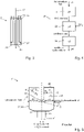
- Fig. 5 depicts a known plasma reactor 1' which was used in the 1990s as a test reactor for the production of carbon particles or C particles (e.g. known from WO 94/14899 A1 ).
- the known plasma reactor 1' comprises a reactor chamber 2' which is enclosed by a reactor wall 3' having a lower part 3a' and a cover 3b'.
- the reactor chamber 2' is substantially cylindrical and has a central axis 4'.
- a plurality of hydrocarbon fluid inlets 5' are provided on the cylindrical outer wall which are adapted to direct a hydrocarbon fluid in the radial direction.
- a plasma burner 7' comprising elongated electrodes (which are not shown in more detail) is fixed to the cover 3b' of the reactor wall 3'.
- the plasma burner 7' has a base part 9' which is fixed to the cover 3b' of the reactor wall 3'. At the other end thereof opposite the base part 9', the plasma burner, 7' has a burner part 11' which projects into the reactor chamber 2'. At the other end of the reactor chamber 2' opposite the plasma burner 7', the plasma reactor 1' has an outlet 15' through which the substances resulting from the fragmentation of the incoming hydrocarbon fluid can escape.
- a plasma 13' is formed in the vicinity of the burner part 11'.
- a hydrocarbon fluid is introduced through the hydrocarbon fluid inlets 5' in a direction towards the plasma 13'.
- the hydrocarbon fluid is decomposed in the absence of oxygen and at operating temperatures of up to 2000°C into hydrogen and C particles which emerge from the outlet 15' of the plasma reactor in the form of a H 2 /C aerosol.
- plasma reactors may be used in plants for producing synthetic hydrocarbons. Such plants are known e.g. from CA 2 842 122 A1 and CA 2 840 297 A1 .
- a plasma burner which has two or more tubular electrodes which are arranged to be mutually coaxial.
- An inlet pipe for introducing a gas that is to be treated by the plasma is arranged coaxially within the inner tubular electrode.
- the inlet pipe ends in the vicinity of a free end of the two tubular electrodes where a plasma arc is formed when the system is in operation.
- the reactor chamber 2' has to be of a certain size which results in there being unused free space 17' (see Fig. 5 ) between the plasma arc and the upper part of the reactor chamber.
- Hot hydrogen in particular accumulated in the free space 17' and this led to a substantial loss of heat.
- the object of the present invention is to provide a plasma reactor in which no deposits or fewer deposits of C particles are produced. This object is achieved by a plasma reactor according to Claim 1, by a method of operating a plasma reactor according to Claim 6 and by a plant for the production of synthetic hydrocarbons according to Claim 9.
- the plasma reactor for decomposing a hydrocarbon fluid comprises a reactor chamber which is enclosed by a reactor wall and comprises at least one hydrocarbon fluid inlet and at least one outlet, and also a plasma burner comprising at least two elongated electrodes which each have a base part that is fixed to the reactor wall and a burner part which projects into the reactor chamber and has a free end wherein the outlet is located at the other end of the reactor chamber opposite the plasma burner.
- the hydrocarbon fluid inlet opens out into the reactor chamber in such a manner that a hydrocarbon fluid flowing out therefrom flows in a space between the reactor wall and the electrodes along at least one electrode to the free end of the burner part.
- Deposits of C particles can be reduced or even entirely prevented by this arrangement of the hydrocarbon fluid inlet since a high rate of flow of the fluid is achieved and the direction of flow of the incoming fluid is directed away from the hydrocarbon fluid inlet. Further, the distance between the hydrocarbon fluid inlet and the base part is smaller than the distance between the hydrocarbon fluid inlet and the free end.
- the plasma is located at the free end of the plasma burner and it also produces radiant heat. The inlets are shielded from the radiant heat. The inlets are shielded from the radiant heat by the body of the plasma burner because the hydrocarbon fluid inlet is arranged in the vicinity of the base part.
- the plasma burner comprises two tubular electrodes which are arranged one within the other; and the hydrocarbon fluid inlet is arranged outside the outer tubular electrode in the radial direction. This arrangement is advantageous when using long-lived tubular electrodes.
- the hydrocarbon fluid inlet is preferably aligned in such a way that the hydrocarbon fluid flowing out therefrom flows in the same direction as the longitudinal extent of the electrodes. Overheating of the electrodes and accumulation of hot substances in the upper region of the reactor are thereby prevented.
- the inflowing hydrocarbon fluid also functions as a thermal shield for the reactor wall.
- the hydrocarbon fluid inlet and the outlet are arranged at opposite ends of the reactor chamber. There is thus a flow in a direction from the hydrocarbon fluid inlet along the plasma burner to the outlet and the reaction time is reduced due to the improved utilization of the hot zone.
- the hydrocarbon fluid inlet has cooled inlet channels in order to reduce the likelihood of depositions of C particles.
- a method of operating a plasma reactor in accordance with the embodiments being described here achieves the aforesaid object in that the hydrocarbon fluid is passed through the reactor chamber with a space velocity of 500 - 1000 1/h with respect to the volume of the reactor chamber. A high rate of flow thus ensues which counteracts the deposition of C particles.
- the hydrocarbon fluid is directed along the plasma burner from the base part toward the free end. Overheating of the electrodes and an accumulation of hot substances in the upper region of the reactor is thereby prevented.
- the inflowing hydrocarbon fluid also functions as a thermal shield for the reactor wall.
- the hydrocarbon fluid is advantageously introduced at a pressure of 15 to 40 bar, preferentially of 18 to 22 bar.
- Gaseous hydrogen which is compressible is formed in the reactor chamber.
- the hydrocarbon fluid is a gas (e.g. natural gas), then this gas too is compressible.
- a higher density of gaseous substances can be achieved within the reactor at the aforementioned pressures, this thereby leading to a higher throughput capacity of the plasma reactor. Consequently, a smaller reactor volume can be used at higher pressures, this thereby offering the advantages of a mechanically stable reactor volume and cost savings during manufacture and operation.
- the plasma reactor described above and the method described above offer advantages in a plant for the production of synthetic hydrocarbons which comprises the following: a plasma reactor for decomposing a hydrocarbon fluid into carbon and hydrogen in accordance with the embodiments described above, a C converter which is adapted to effect the process of converting (a) carbon with CO 2 into CO or, (b) carbon with H 2 O into a CO/H 2 gas mixture, wherein the C converter comprises at least one processing space having at least one input for CO2 or H 2 O, at least one aerosol input and at least one C converter output for a synthesis gas resulting from the conversion process.
- the aerosol input of the C converter is connected to the output of the plasma reactor.
- the plant also comprises a CO converter, wherein the CO converter has a processing space in which a catalyst is arranged, further means for bringing the synthesis gas from the C converter into contact with the catalyst, and a control unit for controlling or regulating the temperature of the catalyst and/or of the synthesis gas to a pre-determined temperature.
- An operating pressure of 15 to 40 bar and especially of 18 to 25 bar prevails in the plasma reactor, in the C converter and in the CO converter.
- a high throughput capacity of the entire plant can thus be achieved.
- the plant can be attached directly to a gas-pipeline.
- hydrocarbon fluid means a fluid containing hydrocarbons (gas, aerosol, liquid).
- the plasma reactor 1 in accordance with the present disclosure comprises a reactor chamber 2 which is enclosed by a reactor wall 3 having a lower part 3a and a cover 3b.
- the reactor chamber 2 could also be divided at a position other than that shown in the Figures.
- the reactor chamber 2 is substantially cylindrical and has a central axis 4.
- a plasma burner 7 having elongated electrodes (not shown in detail) is fixed to the cover 3b of the reactor wall 3.
- the plasma burner 7 has a base part 9 which is fixed to the reactor wall 3 (in particular here, to the cover 3b). At the other end thereof opposite the base part 9, the plasma burner 7 comprises a burner part 11 at a free end 12 of the electrodes which projects into the reactor chamber 2.
- the plasma reactor 1 has an outlet 15 through which the substances resulting from the decomposition of the incoming hydrocarbon fluid can escape.
- the outlet 15 is arranged at the opposite end of the reactor chamber 2 in the direction of flow.
- the plasma reactor 1 comprises hydrocarbon fluid inlets 5 which are arranged in the vicinity of the base part 9 of the plasma burner 7.
- the hydrocarbon fluid inlets 5 open out into the reactor chamber 2 in such a manner that a hydrocarbon fluid flowing out therefrom flows into a free space 17 between the reactor wall 3 and the electrodes of the plasma burner 7 in a direction towards the free end of the electrodes. Due to the arrangement of the hydrocarbon fluid inlets 5 in the vicinity of the base part 9 of the plasma burner 7 that is described here, an adequate spacing d2 from the plasma 13 is maintained (see Figs. 1 and 2 ). Even if the interior of the reactor chamber 2 is smaller (e.g.
- the hydrocarbon fluid inlets 5 can be cooled as is illustrated in Figure 3 .
- the hydrocarbon fluid inlet 5 has an inlet boring 19 which is surrounded by an inlet wall 21.
- the inlet wall 21 is surrounded by cooling channels 23 and can act as a heat insulating layer for the reactor chamber 2.
- cooling agent runs through the cooling channels 23, as indicated by the arrows 25.
- hydrocarbon fluid runs through the inlet boring 19, as shown by the arrow 27. Due to the cooling agent and the hydrocarbon fluid being directed therethrough, the hydrocarbon fluid inlets 5 are cooled significantly below the decomposition temperature of the hydrocarbons, and the probability of a deposit of C particles becomes still smaller.
- the electrodes which are not shown in detail in the Figures are preferably tubular electrodes or tubing electrodes which are arranged one within the other such as is known from US 5 481 080 A (see above).
- the incoming hydrocarbon fluid flows along an electrode, namely, along the outer electrode.
- the hydrocarbon fluid inlets 5 are arranged outside the outer tubular electrode in the radial direction in the case of tubing electrodes.
- rod electrodes it is also conceivable for rod electrodes to be used, for example, two rod electrodes that are arranged next to each other.
- the hydrocarbon fluid flows along two or more electrodes towards their free end.
- the hydrocarbon fluid flows into the space 17 along at least one electrode between the reactor chamber 2 and the plasma burner 7.
- the plasma arc 13 is formed between the electrodes, for preference using H 2 as the plasma gas since this results in any case from the process of decomposing the hydrocarbons.
- H 2 the plasma gas
- any other suitable gases can be selected as the plasma gas, for example, inert gases such as argon or nitrogen which cannot affect or participate in the reaction or fragmentation process in the plasma arc.
- a plasma reactor 1 having a plurality of outlets 15 is shown in Figure 2 .
- a first outlet 15-1 is provided for emitting a H 2 /C aerosol as in Fig. 1 .
- a portion of the H 2 /C aerosol can likewise be emitted via a second outlet 15-2, this portion being used for example in another reactor or process.
- a plasma 13 is formed between the electrodes in the vicinity of the burner part 11.
- the plasma 13 usually has temperatures of between 600°C and 2000°C.
- a hydrocarbon fluid (preferably natural gas) is directed into the reactor chamber 2, in the absence of oxygen, via the hydrocarbon fluid inlets 5 in the direction of the plasma 13.
- the hydrocarbon fluid is introduced in such a way that, in operation, a high space velocity (unit 1/h; Flow rate m3/h of the hydrocarbon fluid related to the volume m 3 of the reactor chamber 2) is reached in the reactor chamber 2.
- a space velocity of 500 - 1000 1/h is considered. Due to the high space velocity and thus the high rate of flow of the substances being introduced, the danger of depositions of solids or C particles on the hydrocarbon inlets 5 and in their proximity is additionally reduced.
- the free space 17 between the reactor wall 3 and the plasma burner 7 is cooled by the inflowing hydrocarbon fluid.
- the free space 17 can be significantly smaller than that in the plasma reactor 1' of the state of the art. Consequently, the reactor chamber 2 can have a smaller interior (a smaller diameter in the case of a cylindrical reactor chamber 2), thereby permitting the reactor chamber 2 to have a more robust construction.
- a robust reactor chamber 2 is advantageous for high operational pressures.
- the hydrocarbons contained in the hydrocarbon fluid are decomposed into C particles and gaseous hydrogen H 2 .
- the decomposition temperature depends on the hydrocarbons that are being introduced and in the case of natural gas for example it is more than 600°C.
- the hydrogen H 2 and the C particles emerge from the outlet 15 of the plasma reactor in the form of a H 2 /C aerosol.
- the hydrocarbon fluid arriving at the hydrocarbon fluid inlets is at a pressure of 18 to 25 bar.
- the plasma reactor 1 can be connected directly to a natural gas pipeline since the pressure in the pipeline lies approximately in this range.
- a pressure of about 18 to 25 bar likewise prevails in the reactor chamber 2 when the system is operational.
- the gaseous constituents such as gaseous hydrogen and natural gas for example are compressed so that the density becomes higher and the throughput can be improved.
- the operation of the plasma reactor 1 in accordance with Figure 2 is exactly the same as that described above. The only difference is that a portion of the hydrogen H 2 is removed through the second outlet 15-2.
- the second outlet 15-2 is arranged in such a way that the C particles can only reach the second outlet 15-2 with difficulty or not at all. This can be achieved for example by means of a labyrinth arrangement or by arranging the second outlet 15-2 such that it is at right angles to the direction of flow of the hydrocarbon fluid or H 2 /C aerosol.
- the second outlet 15-2 can be arranged at an angle of 90° to the central axis 4 and thus to the general direction of flow (as shown in Figure 2 ).
- the second outlet 15-2 could also be arranged at an angle opposed to the general direction of flow, i.e. oriented such as to be inclined to the upper right in Fig. 2 .
- Fig. 4 shows a plant 30 for the production of synthetic hydrocarbons which comprises a plasma reactor 1 as described above, a C converter 32 which is adapted to convert (a) carbon with CO 2 into CO or (b) carbon with H 2 O into a CO/H 2 gas mixture, and a CO converter 34 for producing synthetic functionalised and/or non-functionalised hydrocarbons.
- the C converter 32 comprises at least one processing space having at least one input for CO 2 or H 2 O, at least one aerosol input and at least one C converter output for a synthesis gas resulting from the conversion process (a) or (b).
- the aerosol input of the C converter 32 is connected to the output 15 or 15-1 of the plasma reactor 1 and receives the H2/C aerosol. Conversion of the C particles in the C converter 32 is effected according to any of the following equations: (a) CO2 + C ⁇ 2 CO or (b) C + H 2 O ⁇ CO + H 2 .
- the CO converter 34 for example implements the process of converting the synthesis gas by means of a Fischer-Tropsch process, in particular by means of an SMDS process.
- the CO converter 34 has a processing space in which a catalyst is arranged, further means for bringing the synthesis gas from the C converter 32 into contact with the catalyst, and a control unit for controlling or regulating the temperature of the catalyst and/or the synthesis gas to a pre-determined temperature.
- the hydrocarbon fluid is, for example, natural gas or a similar gas which, when the plant 30 is operational, is delivered directly without any change in pressure from a (natural gas) pipeline to the plasma reactor 1 at a pressure p1 of 15 to 40 bar and in particular, of 18 to 25 bar. The same pressure p1 prevails in the reactor chamber 2 of the plasma reactor 1.
- the synthetic hydrocarbons are then removed from the plant (at a lower ambient pressure p4 of approx. 1 bar).
- a substantially identical operating pressure of 15 to 40 bar (especially of 18 to 25 bar) thus prevails from the plasma reactor 1 up to the CO converter 34.
- the following advantages can be achieved with the plasma reactor 1 described here: prevention of deposits of C particles; utilisation of the reactor region above the plasma 13 (free space 17 which was previously a thermally dead volume); no overheating of the upper region of the reactor since the inflowing hydrocarbon fluid cools the electrodes and the reactor wall; the inflowing hydrocarbon fluid functions as a thermal shield for the reactor wall 3; the reactor chamber can be made of ceramic (e.g.
- the capital outlays can be lowered; a reduction in power consumption by making use of the heat produced by the plasma to good effect; a reduction of the reactor volume; the principle of directing the flow in a direction from the inlets 5 along the plasma burner 7 to the outlet 15 reduces the reaction time due to the improved utilization of the hot zone.
Claims (9)
- Réacteur à plasma (1) pour décomposer un fluide hydrocarboné, qui comprend le suivantune chambre de réacteur (2) qui est entourée par une paroi de réacteur (3, 3a, 3b) et qui a au moins une entrée de fluide hydrocarboné (5) et au moins une sortie (15, 15-1, 15-2) ;un brûleur à plasma (7) ayant au moins deux électrodes allongées qui comprennent chacune une partie de base (9) qui est fixée à la paroi du réacteur (3, 3a, 3b) et une partie de brûleur (11) qui fait saillie dans la chambre du réacteur (2) et a une extrémité libre (12) ;dans lequel la sortie (15, 15-1, 15-2) est située à l'autre extrémité de la chambre du réacteur (2) à l'opposé du brûleur à plasma (7) ;dans lequel l'entrée de fluide hydrocarboné (5) débouche dans la chambre de réacteur (2) de telle manière que le fluide hydrocarboné qui en sort s'écoule dans un espace (17) entre la paroi du réacteur (3, 3a, 3b) et les électrodes le long d'au moins une électrode jusqu'à l'extrémité libre (12) de la partie de brûleur (11) ; etdans lequel la distance entre l'entrée de fluide hydrocarboné (5) et la partie de base (9) est inférieure à la distance entre l'entrée de fluide hydrocarboné (5) et l'extrémité libre (12).
- Réacteur à plasma (1) selon la revendication 1, dans lequel le brûleur à plasma (7) comprend deux électrodes tubulaires disposées l'une dans l'autre ; et
dans lequel l'entrée de fluide hydrocarboné (5) est disposée à l'extérieur de l'électrode tubulaire extérieure dans la direction radiale. - Réacteur à plasma (1) selon l'une quelconque des revendications précédentes, dans lequel l'entrée de fluide hydrocarboné (5) est alignée dans la direction d'extension des électrodes.
- Réacteur à plasma (1) selon l'une quelconque des revendications précédentes, dans lequel l'entrée de fluide hydrocarboné (5) et la sortie (15, 15-1, 15-2) sont disposées aux extrémités opposées de la chambre du réacteur (2).
- Réacteur à plasma (1) selon l'une quelconque des revendications précédentes, dans lequel l'entrée de fluide hydrocarboné (5) comprend des canaux d'entrée refroidis (19).
- Procédé pour opérer un réacteur à plasma (1) selon l'une quelconque des revendications précédentes, dans lequel le fluide hydrocarboné est dirigé à travers la chambre du réacteur (2) à une vitesse spatiale de 500 - 1000 1/h par rapport au volume de la chambre du réacteur (2).
- Procédé selon la revendication 6, dans lequel le fluide hydrocarboné est dirigé depuis la partie de base (9) le long du brûleur à plasma (7) vers l'extrémité libre (12).
- Procédé selon la revendication 7, dans lequel le fluide hydrocarboné est introduit dans la chambre du réacteur (2) à une pression de 18 à 22 bars.
- Installation pour la production d'hydrocarbures synthétiques qui comprend le suivant :- un réacteur à plasma (1) pour décomposer un fluide hydrocarboné en carbone et en hydrogène selon l'une quelconque des revendications 1 à 5 ;- un convertisseur de C (32) qui est adapté pour effectuer le processus de conversion dea) du carbone avec du CO2 en CO ou b) du carbone avec H2O en un mélange gazeux CO/H2, dans lequel le convertisseur C (32) comprend au moins un espace de traitement ayant au moins une entrée pour CO2 ou H2O, au moins une entrée d'aérosol et au moins une sortie de convertisseur C pour un gaz de synthèse résultant du processus de conversion, dans lequel l'entrée d'aérosol du convertisseur C (32) est connectée à la sortie (15 ; 15-1) du réacteur à plasma (1) ; etun convertisseur de CO (34) comprenant un espace de traitement dans lequel un catalyseur est disposé, des moyens supplémentaires pour amener le gaz de synthèse provenant du convertisseur de C (32) en contact avec le catalyseur, et une unité de commande pour commander ou réguler la température du catalyseur et/ou du gaz de synthèse à une température prédéterminée ;dans lequel une pression de fonctionnement de 15 à 40 bars et en particulier de 18 à 25 bars règne dans le réacteur à plasma (1), dans le convertisseur C (32) et dans le convertisseur CO (34).
Applications Claiming Priority (2)
| Application Number | Priority Date | Filing Date | Title |
|---|---|---|---|
| DE102013020375.9A DE102013020375A1 (de) | 2013-12-06 | 2013-12-06 | Plasma-reaktor zum aufspalten eines kohlenwasserstoff-fluids |
| PCT/EP2014/076737 WO2015082689A1 (fr) | 2013-12-06 | 2014-12-05 | Réacteur à plasma et procédé de décomposition d'un fluide hydrocarbure |
Publications (2)
| Publication Number | Publication Date |
|---|---|
| EP3077099A1 EP3077099A1 (fr) | 2016-10-12 |
| EP3077099B1 true EP3077099B1 (fr) | 2022-10-26 |
Family
ID=52023489
Family Applications (1)
| Application Number | Title | Priority Date | Filing Date |
|---|---|---|---|
| EP14811818.5A Active EP3077099B1 (fr) | 2013-12-06 | 2014-12-05 | Réacteur à plasma et procédé de décomposition d'un fluide hydrocarbure |
Country Status (7)
| Country | Link |
|---|---|
| US (1) | US20160296905A1 (fr) |
| EP (1) | EP3077099B1 (fr) |
| CN (1) | CN105934273A (fr) |
| AR (1) | AR098584A1 (fr) |
| DE (1) | DE102013020375A1 (fr) |
| TW (1) | TW201545809A (fr) |
| WO (1) | WO2015082689A1 (fr) |
Families Citing this family (17)
| Publication number | Priority date | Publication date | Assignee | Title |
|---|---|---|---|---|
| US10370539B2 (en) | 2014-01-30 | 2019-08-06 | Monolith Materials, Inc. | System for high temperature chemical processing |
| US11939477B2 (en) | 2014-01-30 | 2024-03-26 | Monolith Materials, Inc. | High temperature heat integration method of making carbon black |
| CA3032246C (fr) | 2015-07-29 | 2023-12-12 | Monolith Materials, Inc. | Procede et appareil de conception d'alimentation electrique de torche a plasma a courant continu |
| WO2017040704A1 (fr) | 2015-09-04 | 2017-03-09 | Plasmerica, Llc | Réacteur gaz vers liquide et procédé d'utilisation |
| DE102015218098A1 (de) * | 2015-09-21 | 2017-03-23 | Deutsche Lufthansa Ag | Verfahren zur thermischen Spaltung von Kohlenwasserstoffen und korrespondierende Vorrichtung |
| DE102015218514A1 (de) * | 2015-09-25 | 2017-03-30 | Deutsche Lufthansa Ag | Reaktor zur thermischen Spaltung von Kohlenwasserstoffen und korrespondierendes Verfahren |
| DE102015219862A1 (de) * | 2015-10-13 | 2017-04-13 | Deutsche Lufthansa Ag | Vorrichtung und Verfahren zur Erzeugung von Synthesegas |
| DE102015014007A1 (de) * | 2015-10-30 | 2017-05-04 | CCP Technology GmbH | Vorrichtung und Verfahren zum Erzeugen von Synthesegas |
| GB201612776D0 (en) | 2016-07-22 | 2016-09-07 | Xgas As | Process and apparatus for decomposing a hydrocarbon fuel |
| DE102016014362A1 (de) * | 2016-12-02 | 2018-06-07 | CCP Technology GmbH | Plasmareaktor und Verfahren zum Betrieb eines Plasmareaktors |
| EP3592810A4 (fr) | 2017-03-08 | 2021-01-27 | Monolith Materials, Inc. | Systèmes et procédés de production de particules de carbone à l'aide un gaz de transfert thermique |
| EP3781301A4 (fr) | 2018-04-16 | 2022-01-26 | Plasmerica, LLC | Réacteur gaz à gaz et procédé d'utilisation |
| CN111312411B (zh) * | 2018-12-11 | 2022-10-21 | 核工业西南物理研究院 | 液化惰性气体射流注入防护等离子体破裂的方法 |
| FR3112767B1 (fr) * | 2020-07-27 | 2023-05-12 | Plenesys | Production optimisée d’hydrogène à partir d’un hydrocarbure. |
| CA3233950A1 (fr) * | 2021-10-08 | 2023-04-13 | Mathew Leis | Systemes et procedes de traitement electrique |
| WO2023197070A1 (fr) * | 2022-04-14 | 2023-10-19 | Acceleware Ltd. | Systèmes et procédés pour la production d'hydrogène par pyrolyse dans un réacteur à lit fluidisé supporté à diélectrophorèse (dep) |
| DE102022124117A1 (de) | 2022-09-20 | 2024-03-21 | Caphenia Gmbh | Plasma-Reaktor |
Family Cites Families (9)
| Publication number | Priority date | Publication date | Assignee | Title |
|---|---|---|---|---|
| SE8501005L (sv) * | 1985-03-01 | 1986-09-02 | Skf Steel Eng Ab | Termisk reformering av gasformiga kolveten |
| NO174180C (no) * | 1991-12-12 | 1994-03-23 | Kvaerner Eng | Innföringsrör for brenner for kjemiske prosesser |
| NO176969C (no) * | 1992-12-23 | 1995-06-28 | Kvaerner Eng | Fremgangsmåte til styring av fremstillingen av karbon og hydrogen ved pyrolyse av hydrokarboner, samt anordning for bruk ved fremgangsmåten |
| FR2757499B1 (fr) * | 1996-12-24 | 2001-09-14 | Etievant Claude | Generateur d'hydrogene |
| DE10162245A1 (de) * | 2001-12-18 | 2003-07-10 | Siemens Ag | Verfahren zur selektiven Erzeugung reaktiver Teilchen |
| US7033551B2 (en) * | 2002-01-23 | 2006-04-25 | Battelle Energy Alliance, Llc | Apparatus and methods for direct conversion of gaseous hydrocarbons to liquids |
| US9573110B2 (en) * | 2011-10-03 | 2017-02-21 | NitricGen, Inc. | Apparatus and method for generating nitric oxide in controlled and accurate amounts |
| GB2497546B (en) * | 2011-12-12 | 2015-08-05 | Tetronics International Ltd | Base metal recovery |
| DE102012010542A1 (de) * | 2011-12-20 | 2013-06-20 | CCP Technology GmbH | Verfahren und anlage zur erzeugung von synthesegas |
-
2013
- 2013-12-06 DE DE102013020375.9A patent/DE102013020375A1/de active Pending
-
2014
- 2014-12-02 AR ARP140104480A patent/AR098584A1/es unknown
- 2014-12-05 TW TW103142269A patent/TW201545809A/zh unknown
- 2014-12-05 US US15/100,704 patent/US20160296905A1/en not_active Abandoned
- 2014-12-05 WO PCT/EP2014/076737 patent/WO2015082689A1/fr active Application Filing
- 2014-12-05 CN CN201480074111.5A patent/CN105934273A/zh active Pending
- 2014-12-05 EP EP14811818.5A patent/EP3077099B1/fr active Active
Also Published As
| Publication number | Publication date |
|---|---|
| AR098584A1 (es) | 2016-06-01 |
| EP3077099A1 (fr) | 2016-10-12 |
| US20160296905A1 (en) | 2016-10-13 |
| CN105934273A (zh) | 2016-09-07 |
| DE102013020375A1 (de) | 2015-06-11 |
| WO2015082689A1 (fr) | 2015-06-11 |
| TW201545809A (zh) | 2015-12-16 |
Similar Documents
| Publication | Publication Date | Title |
|---|---|---|
| EP3077099B1 (fr) | Réacteur à plasma et procédé de décomposition d'un fluide hydrocarbure | |
| US8636960B2 (en) | Plasma reactor for carrying out gas reactions and method for the plasma-supported reaction of gases | |
| Cormier et al. | Syngas production via methane steam reforming with oxygen: plasma reactors versus chemical reactors | |
| JP5159513B2 (ja) | 炭素ナノチューブの合成装置 | |
| CA2595872A1 (fr) | Synthese de nanopoudres par plasma a induction | |
| SA516380482B1 (ar) | جهاز وطريقة لتخليق بلازما لمنتجات جرافيتية تتضمن جرافين | |
| JP5933704B2 (ja) | メタン含有のガス容量流を改質する方法 | |
| US20100055017A1 (en) | Methods for the production of ultrafine metal carbide particles and hydrogen | |
| GB2573222A (en) | Method of activating a catalyst, reactor, and method of obtaining hydrocarbons in the fischer-tropsch process | |
| KR20080105344A (ko) | 플라즈마를 이용한 수소 및 카본블랙 제조장치 | |
| WO2015128673A2 (fr) | Procédé et appareil de conversion catalytique assistée par plasma | |
| WO2012031338A1 (fr) | Procédé et appareil de production d'un combustible | |
| Jasiński et al. | Hydrogen production via methane reforming using various microwave plasma sources | |
| CA3233950A1 (fr) | Systemes et procedes de traitement electrique | |
| US9067849B2 (en) | Systems and methods for producing fuel from parallel processed syngas | |
| US20180327260A1 (en) | Apparatus and process for production of synthesis gas | |
| EP3238817B1 (fr) | Procédé pour l'oxydation partielle de carburants et dispositif d'exécution dudit procédé | |
| JP7403535B2 (ja) | Co2および1または複数の炭化水素を含むガス流の処理による合成ガスの製造方法 | |
| US10214464B2 (en) | Steady state high temperature reactor | |
| KR20090013310A (ko) | 탄소나노튜브 합성 방법 및 장치 | |
| JP2018176125A (ja) | 触媒充填方法 | |
| Jasiński et al. | Production of hydrogen via methane reforming using atmospheric pressure microwave plasma source with CO2 swirl | |
| Jasiński et al. | Production of hydrogen via methane conversion using microwave plasma source with CO2 or CH4 swirl | |
| Zhu et al. | Plasma Treatment of Ni Catalyst for Partial Oxidation of Methane | |
| CA2984551A1 (fr) | Dispositif et procede de production d'un gaz de synthese |
Legal Events
| Date | Code | Title | Description |
|---|---|---|---|
| PUAI | Public reference made under article 153(3) epc to a published international application that has entered the european phase |
Free format text: ORIGINAL CODE: 0009012 |
|
| 17P | Request for examination filed |
Effective date: 20160531 |
|
| AK | Designated contracting states |
Kind code of ref document: A1 Designated state(s): AL AT BE BG CH CY CZ DE DK EE ES FI FR GB GR HR HU IE IS IT LI LT LU LV MC MK MT NL NO PL PT RO RS SE SI SK SM TR |
|
| AX | Request for extension of the european patent |
Extension state: BA ME |
|
| DAX | Request for extension of the european patent (deleted) | ||
| STAA | Information on the status of an ep patent application or granted ep patent |
Free format text: STATUS: EXAMINATION IS IN PROGRESS |
|
| 17Q | First examination report despatched |
Effective date: 20191218 |
|
| RAP1 | Party data changed (applicant data changed or rights of an application transferred) |
Owner name: CAPHENIA GMBH |
|
| STAA | Information on the status of an ep patent application or granted ep patent |
Free format text: STATUS: EXAMINATION IS IN PROGRESS |
|
| REG | Reference to a national code |
Ref country code: DE Ref legal event code: R079 Ref document number: 602014085346 Country of ref document: DE Free format text: PREVIOUS MAIN CLASS: B01J0019080000 Ipc: C01B0032050000 |
|
| GRAP | Despatch of communication of intention to grant a patent |
Free format text: ORIGINAL CODE: EPIDOSNIGR1 |
|
| STAA | Information on the status of an ep patent application or granted ep patent |
Free format text: STATUS: GRANT OF PATENT IS INTENDED |
|
| RIC1 | Information provided on ipc code assigned before grant |
Ipc: H05H 1/48 20060101ALI20220408BHEP Ipc: C10G 2/00 20060101ALI20220408BHEP Ipc: B01J 19/08 20060101ALI20220408BHEP Ipc: C01B 3/24 20060101ALI20220408BHEP Ipc: C01B 32/05 20170101AFI20220408BHEP |
|
| INTG | Intention to grant announced |
Effective date: 20220516 |
|
| GRAS | Grant fee paid |
Free format text: ORIGINAL CODE: EPIDOSNIGR3 |
|
| GRAA | (expected) grant |
Free format text: ORIGINAL CODE: 0009210 |
|
| STAA | Information on the status of an ep patent application or granted ep patent |
Free format text: STATUS: THE PATENT HAS BEEN GRANTED |
|
| RAP3 | Party data changed (applicant data changed or rights of an application transferred) |
Owner name: CAPHENIA GMBH |
|
| AK | Designated contracting states |
Kind code of ref document: B1 Designated state(s): AL AT BE BG CH CY CZ DE DK EE ES FI FR GB GR HR HU IE IS IT LI LT LU LV MC MK MT NL NO PL PT RO RS SE SI SK SM TR |
|
| REG | Reference to a national code |
Ref country code: GB Ref legal event code: FG4D |
|
| REG | Reference to a national code |
Ref country code: CH Ref legal event code: EP |
|
| REG | Reference to a national code |
Ref country code: DE Ref legal event code: R096 Ref document number: 602014085346 Country of ref document: DE |
|
| REG | Reference to a national code |
Ref country code: AT Ref legal event code: REF Ref document number: 1526942 Country of ref document: AT Kind code of ref document: T Effective date: 20221115 |
|
| REG | Reference to a national code |
Ref country code: IE Ref legal event code: FG4D |
|
| REG | Reference to a national code |
Ref country code: NO Ref legal event code: T2 Effective date: 20221026 |
|
| REG | Reference to a national code |
Ref country code: NL Ref legal event code: FP |
|
| REG | Reference to a national code |
Ref country code: LT Ref legal event code: MG9D |
|
| PGFP | Annual fee paid to national office [announced via postgrant information from national office to epo] |
Ref country code: BE Payment date: 20221220 Year of fee payment: 9 |
|
| PG25 | Lapsed in a contracting state [announced via postgrant information from national office to epo] |
Ref country code: SE Free format text: LAPSE BECAUSE OF FAILURE TO SUBMIT A TRANSLATION OF THE DESCRIPTION OR TO PAY THE FEE WITHIN THE PRESCRIBED TIME-LIMIT Effective date: 20221026 Ref country code: PT Free format text: LAPSE BECAUSE OF FAILURE TO SUBMIT A TRANSLATION OF THE DESCRIPTION OR TO PAY THE FEE WITHIN THE PRESCRIBED TIME-LIMIT Effective date: 20230227 Ref country code: LT Free format text: LAPSE BECAUSE OF FAILURE TO SUBMIT A TRANSLATION OF THE DESCRIPTION OR TO PAY THE FEE WITHIN THE PRESCRIBED TIME-LIMIT Effective date: 20221026 Ref country code: FI Free format text: LAPSE BECAUSE OF FAILURE TO SUBMIT A TRANSLATION OF THE DESCRIPTION OR TO PAY THE FEE WITHIN THE PRESCRIBED TIME-LIMIT Effective date: 20221026 Ref country code: ES Free format text: LAPSE BECAUSE OF FAILURE TO SUBMIT A TRANSLATION OF THE DESCRIPTION OR TO PAY THE FEE WITHIN THE PRESCRIBED TIME-LIMIT Effective date: 20221026 |
|
| PGFP | Annual fee paid to national office [announced via postgrant information from national office to epo] |
Ref country code: CH Payment date: 20230103 Year of fee payment: 9 |
|
| PG25 | Lapsed in a contracting state [announced via postgrant information from national office to epo] |
Ref country code: RS Free format text: LAPSE BECAUSE OF FAILURE TO SUBMIT A TRANSLATION OF THE DESCRIPTION OR TO PAY THE FEE WITHIN THE PRESCRIBED TIME-LIMIT Effective date: 20221026 Ref country code: PL Free format text: LAPSE BECAUSE OF FAILURE TO SUBMIT A TRANSLATION OF THE DESCRIPTION OR TO PAY THE FEE WITHIN THE PRESCRIBED TIME-LIMIT Effective date: 20221026 Ref country code: LV Free format text: LAPSE BECAUSE OF FAILURE TO SUBMIT A TRANSLATION OF THE DESCRIPTION OR TO PAY THE FEE WITHIN THE PRESCRIBED TIME-LIMIT Effective date: 20221026 Ref country code: IS Free format text: LAPSE BECAUSE OF FAILURE TO SUBMIT A TRANSLATION OF THE DESCRIPTION OR TO PAY THE FEE WITHIN THE PRESCRIBED TIME-LIMIT Effective date: 20230226 Ref country code: HR Free format text: LAPSE BECAUSE OF FAILURE TO SUBMIT A TRANSLATION OF THE DESCRIPTION OR TO PAY THE FEE WITHIN THE PRESCRIBED TIME-LIMIT Effective date: 20221026 Ref country code: GR Free format text: LAPSE BECAUSE OF FAILURE TO SUBMIT A TRANSLATION OF THE DESCRIPTION OR TO PAY THE FEE WITHIN THE PRESCRIBED TIME-LIMIT Effective date: 20230127 |
|
| P01 | Opt-out of the competence of the unified patent court (upc) registered |
Effective date: 20230526 |
|
| REG | Reference to a national code |
Ref country code: DE Ref legal event code: R097 Ref document number: 602014085346 Country of ref document: DE |
|
| PG25 | Lapsed in a contracting state [announced via postgrant information from national office to epo] |
Ref country code: SM Free format text: LAPSE BECAUSE OF FAILURE TO SUBMIT A TRANSLATION OF THE DESCRIPTION OR TO PAY THE FEE WITHIN THE PRESCRIBED TIME-LIMIT Effective date: 20221026 Ref country code: RO Free format text: LAPSE BECAUSE OF FAILURE TO SUBMIT A TRANSLATION OF THE DESCRIPTION OR TO PAY THE FEE WITHIN THE PRESCRIBED TIME-LIMIT Effective date: 20221026 Ref country code: EE Free format text: LAPSE BECAUSE OF FAILURE TO SUBMIT A TRANSLATION OF THE DESCRIPTION OR TO PAY THE FEE WITHIN THE PRESCRIBED TIME-LIMIT Effective date: 20221026 Ref country code: DK Free format text: LAPSE BECAUSE OF FAILURE TO SUBMIT A TRANSLATION OF THE DESCRIPTION OR TO PAY THE FEE WITHIN THE PRESCRIBED TIME-LIMIT Effective date: 20221026 Ref country code: CZ Free format text: LAPSE BECAUSE OF FAILURE TO SUBMIT A TRANSLATION OF THE DESCRIPTION OR TO PAY THE FEE WITHIN THE PRESCRIBED TIME-LIMIT Effective date: 20221026 |
|
| PG25 | Lapsed in a contracting state [announced via postgrant information from national office to epo] |
Ref country code: SK Free format text: LAPSE BECAUSE OF FAILURE TO SUBMIT A TRANSLATION OF THE DESCRIPTION OR TO PAY THE FEE WITHIN THE PRESCRIBED TIME-LIMIT Effective date: 20221026 Ref country code: LU Free format text: LAPSE BECAUSE OF NON-PAYMENT OF DUE FEES Effective date: 20221205 Ref country code: AL Free format text: LAPSE BECAUSE OF FAILURE TO SUBMIT A TRANSLATION OF THE DESCRIPTION OR TO PAY THE FEE WITHIN THE PRESCRIBED TIME-LIMIT Effective date: 20221026 |
|
| PLBE | No opposition filed within time limit |
Free format text: ORIGINAL CODE: 0009261 |
|
| STAA | Information on the status of an ep patent application or granted ep patent |
Free format text: STATUS: NO OPPOSITION FILED WITHIN TIME LIMIT |
|
| 26N | No opposition filed |
Effective date: 20230727 |
|
| PG25 | Lapsed in a contracting state [announced via postgrant information from national office to epo] |
Ref country code: SI Free format text: LAPSE BECAUSE OF FAILURE TO SUBMIT A TRANSLATION OF THE DESCRIPTION OR TO PAY THE FEE WITHIN THE PRESCRIBED TIME-LIMIT Effective date: 20221026 |
|
| PGFP | Annual fee paid to national office [announced via postgrant information from national office to epo] |
Ref country code: GB Payment date: 20231220 Year of fee payment: 10 |
|
| PGFP | Annual fee paid to national office [announced via postgrant information from national office to epo] |
Ref country code: NO Payment date: 20231218 Year of fee payment: 10 Ref country code: NL Payment date: 20231219 Year of fee payment: 10 Ref country code: IE Payment date: 20231218 Year of fee payment: 10 Ref country code: FR Payment date: 20231220 Year of fee payment: 10 Ref country code: DE Payment date: 20231214 Year of fee payment: 10 Ref country code: AT Payment date: 20231214 Year of fee payment: 10 |
|
| PGFP | Annual fee paid to national office [announced via postgrant information from national office to epo] |
Ref country code: BE Payment date: 20231218 Year of fee payment: 10 |
|
| PG25 | Lapsed in a contracting state [announced via postgrant information from national office to epo] |
Ref country code: HU Free format text: LAPSE BECAUSE OF FAILURE TO SUBMIT A TRANSLATION OF THE DESCRIPTION OR TO PAY THE FEE WITHIN THE PRESCRIBED TIME-LIMIT; INVALID AB INITIO Effective date: 20141205 |