EP3076890B2 - Skin treatment apparatus utilising intense pulsed light (ipl) - Google Patents
Skin treatment apparatus utilising intense pulsed light (ipl) Download PDFInfo
- Publication number
- EP3076890B2 EP3076890B2 EP14809688.6A EP14809688A EP3076890B2 EP 3076890 B2 EP3076890 B2 EP 3076890B2 EP 14809688 A EP14809688 A EP 14809688A EP 3076890 B2 EP3076890 B2 EP 3076890B2
- Authority
- EP
- European Patent Office
- Prior art keywords
- skin
- energy
- control system
- charge storage
- treatment
- Prior art date
- Legal status (The legal status is an assumption and is not a legal conclusion. Google has not performed a legal analysis and makes no representation as to the accuracy of the status listed.)
- Active
Links
Images


Classifications
-
- A—HUMAN NECESSITIES
- A61—MEDICAL OR VETERINARY SCIENCE; HYGIENE
- A61B—DIAGNOSIS; SURGERY; IDENTIFICATION
- A61B18/00—Surgical instruments, devices or methods for transferring non-mechanical forms of energy to or from the body
- A61B18/18—Surgical instruments, devices or methods for transferring non-mechanical forms of energy to or from the body by applying electromagnetic radiation, e.g. microwaves
-
- A—HUMAN NECESSITIES
- A61—MEDICAL OR VETERINARY SCIENCE; HYGIENE
- A61N—ELECTROTHERAPY; MAGNETOTHERAPY; RADIATION THERAPY; ULTRASOUND THERAPY
- A61N5/00—Radiation therapy
- A61N5/06—Radiation therapy using light
- A61N5/0613—Apparatus adapted for a specific treatment
- A61N5/0616—Skin treatment other than tanning
- A61N5/0617—Hair treatment
-
- A—HUMAN NECESSITIES
- A61—MEDICAL OR VETERINARY SCIENCE; HYGIENE
- A61B—DIAGNOSIS; SURGERY; IDENTIFICATION
- A61B18/00—Surgical instruments, devices or methods for transferring non-mechanical forms of energy to or from the body
- A61B18/18—Surgical instruments, devices or methods for transferring non-mechanical forms of energy to or from the body by applying electromagnetic radiation, e.g. microwaves
- A61B18/20—Surgical instruments, devices or methods for transferring non-mechanical forms of energy to or from the body by applying electromagnetic radiation, e.g. microwaves using laser
- A61B18/203—Surgical instruments, devices or methods for transferring non-mechanical forms of energy to or from the body by applying electromagnetic radiation, e.g. microwaves using laser applying laser energy to the outside of the body
-
- A—HUMAN NECESSITIES
- A61—MEDICAL OR VETERINARY SCIENCE; HYGIENE
- A61N—ELECTROTHERAPY; MAGNETOTHERAPY; RADIATION THERAPY; ULTRASOUND THERAPY
- A61N5/00—Radiation therapy
- A61N5/06—Radiation therapy using light
- A61N5/0613—Apparatus adapted for a specific treatment
- A61N5/0614—Tanning
-
- A—HUMAN NECESSITIES
- A61—MEDICAL OR VETERINARY SCIENCE; HYGIENE
- A61N—ELECTROTHERAPY; MAGNETOTHERAPY; RADIATION THERAPY; ULTRASOUND THERAPY
- A61N5/00—Radiation therapy
- A61N5/06—Radiation therapy using light
- A61N5/0613—Apparatus adapted for a specific treatment
- A61N5/0616—Skin treatment other than tanning
-
- A—HUMAN NECESSITIES
- A61—MEDICAL OR VETERINARY SCIENCE; HYGIENE
- A61B—DIAGNOSIS; SURGERY; IDENTIFICATION
- A61B18/00—Surgical instruments, devices or methods for transferring non-mechanical forms of energy to or from the body
- A61B2018/00315—Surgical instruments, devices or methods for transferring non-mechanical forms of energy to or from the body for treatment of particular body parts
- A61B2018/00452—Skin
- A61B2018/00476—Hair follicles
-
- A—HUMAN NECESSITIES
- A61—MEDICAL OR VETERINARY SCIENCE; HYGIENE
- A61B—DIAGNOSIS; SURGERY; IDENTIFICATION
- A61B18/00—Surgical instruments, devices or methods for transferring non-mechanical forms of energy to or from the body
- A61B2018/00636—Sensing and controlling the application of energy
- A61B2018/00642—Sensing and controlling the application of energy with feedback, i.e. closed loop control
-
- A—HUMAN NECESSITIES
- A61—MEDICAL OR VETERINARY SCIENCE; HYGIENE
- A61B—DIAGNOSIS; SURGERY; IDENTIFICATION
- A61B18/00—Surgical instruments, devices or methods for transferring non-mechanical forms of energy to or from the body
- A61B2018/00636—Sensing and controlling the application of energy
- A61B2018/00696—Controlled or regulated parameters
- A61B2018/00702—Power or energy
- A61B2018/00708—Power or energy switching the power on or off
-
- A—HUMAN NECESSITIES
- A61—MEDICAL OR VETERINARY SCIENCE; HYGIENE
- A61B—DIAGNOSIS; SURGERY; IDENTIFICATION
- A61B18/00—Surgical instruments, devices or methods for transferring non-mechanical forms of energy to or from the body
- A61B2018/00636—Sensing and controlling the application of energy
- A61B2018/00773—Sensed parameters
- A61B2018/00779—Power or energy
- A61B2018/00785—Reflected power
-
- A—HUMAN NECESSITIES
- A61—MEDICAL OR VETERINARY SCIENCE; HYGIENE
- A61B—DIAGNOSIS; SURGERY; IDENTIFICATION
- A61B18/00—Surgical instruments, devices or methods for transferring non-mechanical forms of energy to or from the body
- A61B18/18—Surgical instruments, devices or methods for transferring non-mechanical forms of energy to or from the body by applying electromagnetic radiation, e.g. microwaves
- A61B2018/1807—Surgical instruments, devices or methods for transferring non-mechanical forms of energy to or from the body by applying electromagnetic radiation, e.g. microwaves using light other than laser radiation
-
- A—HUMAN NECESSITIES
- A61—MEDICAL OR VETERINARY SCIENCE; HYGIENE
- A61N—ELECTROTHERAPY; MAGNETOTHERAPY; RADIATION THERAPY; ULTRASOUND THERAPY
- A61N5/00—Radiation therapy
- A61N5/06—Radiation therapy using light
- A61N2005/0626—Monitoring, verifying, controlling systems and methods
-
- A—HUMAN NECESSITIES
- A61—MEDICAL OR VETERINARY SCIENCE; HYGIENE
- A61N—ELECTROTHERAPY; MAGNETOTHERAPY; RADIATION THERAPY; ULTRASOUND THERAPY
- A61N5/00—Radiation therapy
- A61N5/06—Radiation therapy using light
- A61N2005/0626—Monitoring, verifying, controlling systems and methods
- A61N2005/0627—Dose monitoring systems and methods
-
- A—HUMAN NECESSITIES
- A61—MEDICAL OR VETERINARY SCIENCE; HYGIENE
- A61N—ELECTROTHERAPY; MAGNETOTHERAPY; RADIATION THERAPY; ULTRASOUND THERAPY
- A61N5/00—Radiation therapy
- A61N5/06—Radiation therapy using light
- A61N2005/0635—Radiation therapy using light characterised by the body area to be irradiated
- A61N2005/0643—Applicators, probes irradiating specific body areas in close proximity
- A61N2005/0644—Handheld applicators
Definitions
- the present invention relates to an apparatus for treating skin by means of intense pulsed light (IPL).
- Skin treatment apparatus is known in the art for treatment of, for example, cosmetic purposes such as hair depilation, minimisation of skin blemishes or skin rejuvenation, as well as dermatological treatment of skin conditions such as acne or rosacea.
- the skin is exposed to dosages of radiation such as from a laser source or light source where the radiation is targeted to the skin and the energy intensity and pulse duration is controlled.
- the radiation source is targeted to cause heating of the hair root causing the hair root to die.
- Apparatus for use in treating the skin using intense pulsed light (IPL) in particular is now increasingly available for non-professional use, i.e., for the consumer market.
- GB2496895 discloses an apparatus including a light source, a control unit and a base unit.
- the control unit removably docks from the base and comprises a sensor which can detect skin tone.
- This control unit is therefore positioned on the skin and detects the skin tone and is then replaced into the base unit wherein the base unit then determines the power level of radiation to be generated by the light source.
- the head unit (20) is then repositioned onto the skin at the location for which the skin tone has been determined and the skin is treated with a pulse of light without the requirement for the user to select an energy level output. This means that the step of the user selecting the energy to be output from the light source is removed thus reducing the potential harmful effect of a user misusing the apparatus.
- WO02/085229 also discloses a device for treating skin by means of radiation pulses such as a laser source.
- the aim of the invention disclosed in WO02/085229 is again to reduce undesirable side effects on the skin such as skin irritation and pain through misuse of the device. This is achieved through detecting a biophysical property of the skin such as the skin tone.
- the device comprises a housing (3) which is portable and can be placed on or moved over skin (7) to be treated.
- the housing (3) accommodates a radiation source, in particular a laser source (9) such as a laser diode.
- the housing is positioned on the skin and an image is recorded of the part of the skin situated directly in front of an exit opening (15).
- the positions of the hair root (39) of the hairs (41) are determined and the laser source (9) is manipulated in order that the hair roots (39) are successively heated in such a manner that they die. Protection against an impermissible overdose of the laser pulse, however, is achieved by using a detector (43) which detects, for example, the temperature of the skin resulting from exposure to a series of test laser pulses. The detector measures the temperature of the skin after each pulse to ensure that a maximum temperature is not exceeded. In such a manner the permissible dose of energy from a laser source is controlled.
- WO02/085229 discloses a further embodiment wherein a detector is utilised which measures the scattering coefficient and/or absorption coefficient of the skin for light of a predetermined wavelength and the pulse dose is determined by means of the scattering coefficient and/or absorption coefficient of the skin.
- GB2496895 determines the light energy pulse dependent upon skin tone, however, relies on a user then repositioning a treatment head onto a correct location for which the skin tone has been determined. It is unlikely that positioning of the treatment head accurately reflects the positioning of the detector thus giving the possibility of incorrect output energy. Further, there is significant time delay between sensing the skin tone and the time of the treatment.
- WO02/085229 overcomes the problem of inaccurate positioning of the treatment head by utilising a head which incorporates both a detector for detecting a parameter of the skin such as temperature, scattering coefficient and/or absorption and treats the skin dependent on this outcome. Whilst this is possible when utilising a laser pulse there are distinct safety issues associated with the use of laser pulses.
- FIG. 1a-c a prior art system is schematically presented as a block diagram showing how an IPL system functions.
- Figure 1a identifies components in a prior art system and includes an energy storage device (20), typically comprising a capacitor, is arranged to release energy to the flashlamp (22) which in turn outputs a pulse of light energy to the skin under operation of the lamp trigger circuit (24).
- the energy storage device (20) is charged by a charge circuit (26) where the charge circuit (26) and lamp trigger circuit (24) are under operation of the control circuit (28).
- a user input (30) is provided such as a trigger which is depressed to enable the control circuit (28) to cause actuation of the lamp trigger circuit (24) causing release of charge from the energy storage device (20) to the flashlamp (22).
- control circuit (28) In order to control the value of energy stored by the energy storage device (20) an input is provided to the control circuit (28) which is either from a sensor (32) arranged to measure a skin parameter such as skin tone as represented in Figure 1a or by a user selected input described in more detail with respect to Figure 1b .
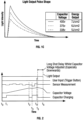
- FIG. 1b Represented in Figure 1b is a schematic representation of the change over time of the light output, the user input, the capacitor voltage and the capacitor charging.
- T1 a user turns the apparatus on and the output power required for treatment of the skin is determined. In most prior art systems this is determined by a user visually comparing their skin tone against a chart and manually selecting a power level. In GB2496895 this is determined by a control unit having a sensor to determine the preferred power output dependent on the skin tone thereby removing the requirement for the user to make a comparison with a known scale.
- the control circuit (28) charges the capacitor during which time the capacitor voltage increases until T2 is reached.
- the time between T2 and T3 represents the time in which the capacitor is charged until the user operates the user input (30) between T3 and T4.
- the charge on the capacitor is released to the flashlamp and the light pulse is released onto the skin as represented by the curve between T4 and T5. The cycle is repeated as necessary on another area of skin.
- Figure 1c presents the change in light intensity over time dependent on the power output required. As such if the sensor or manual user input requires a power output of 7J/cm 2 then the capacitor is charged to 400V. Alternatively, if the skin tone is fair or light, then an energy output of 5J/cm 2 may be more appropriate and the capacitor is charged to a voltage of 338V.
- the sensor measurement is recorded at T5 and the sensor measurement identifies that the required energy output should be less than would be achieved by the stored energy or the capacitor at that time. Accordingly, at T5 the capacitor charging ceases and the capacitor voltage is decreased. During the time between T5 and T6 the user input has been actuated, however, the capacitor voltage must decrease. The problem with this is that reduction of the capacitor voltage to reflect the required output for the current sensor measurement takes significant time which may be, for example, between three to ten seconds. This is undesirable in an automated system wherein the energy output is dependent on a sensor output as again it may lead to further movement of the apparatus on the skin thereby creating further delays to further sensor measurements being recorded and again would cause difficulties for a user in knowing when the apparatus was functioning correctly.
- the present invention provides an improved apparatus that can be used by an individual who is not a medical practitioner thus ensures fast, effective treatment without any of the safety implications or disadvantages identified above.
- the apparatus is preferably a hair depilation apparatus.
- the treatment energy dose may be controlled upon release from the charge storage device, so the treatment energy dose may be free discharge of the charge storage device and/or a modulated discharge that may extend the treatment time period. This means that the actual light intensity contacting the skin can be controlled, and the light output delivered over an extended time frame if required to reduce intensity for the user.
- the treatment energy dose can be manipulated before discharge for example through a user input, thereby increasing or decreasing the treatment energy dose for example.
- the control system terminates discharge of the charge storage device once the treatment energy dose has been delivered where the treatment energy dose can be determined solely on the basis of the sensor measurement or to include an additional input such as a user input to provide improved efficacy for a specific user.
- the charge storage device comprises a plurality of individual charge storage elements
- the control system is arranged to control discharge of the plurality of individual charge storage elements to deliver the treatment energy dose.
- the control system is beneficially arranged to selectively discharge one or more of the plurality of charge storage elements to deliver the treatment energy dose.
- one or more individual charge storage elements can be activated and preferably discharged independently of the other individual charge storage elements. For example, if two individual charge elements are provided, one charge element can be discharged independently of the other. If there are three charge element for example two charge elements can be discharged simultaneously or sequentially and the other left charged, or for example all three charge elements can be discharged again simultaneously, sequentially or a combination thereof, depending on the determined energy treatment dose.
- control of the energy output to the skin is achieved through discharge of one or more individual charge storage elements.
- a plurality of charge storage elements may be charged, again preferably independently of the sensor measurement meaning that the output energy can be adjusted to the required treatment intensity with no time delay. It is beneficial that in order to achieve the desired energy output to the skin, two or more of the individual charge storage elements may be charged to different voltages. It will further be appreciated that the control system may be arranged to modulate discharge of energy from the plurality of charge storage elements.
- control system is arranged to enable charging of the charge storage device in a two or more stage operation, wherein a first stage charging is to an intermediate energy level, and a second or further stage to an energy level sufficient to deliver the treatment energy dose.
- the charge storage device can therefore be effectively charged to a minimum voltage between energy doses supplied to the skin and the charge storage device may effectively be 'topped up' dependent on the sensor measurement.
- the control system is arranged to partially charge the charge storage device dependent on the sensor measurement.
- control system is arranged to modulate discharge of the charge storage device to deliver the treatment energy dose.
- This provides a further alternative means of ensuring that the correct treatment energy dose may be delivered to the light emitting element and subsequently to the user derived using the sensor measurement.
- An energy modulation arrangement is beneficially provided to modulate the supply of treatment energy dose to the light emitting element.
- the modulation arrangement beneficially comprises an electronic switch such as a Mosfet. Pulse width modulation or pulse duration modulation may be utilised to control discharge of the charge storage device meaning that the output light from the light emitting element can be manipulated. This means that the intensity of the light hitting the user's skin may be controlled, and may be changed over time.
- the apparatus preferably further comprises a housing arranged to accommodate the light emitting element and the sensor. This means that accuracy of the sensed skin parameter with respect to the actual area of the skin treated is maintained.
- the light emitting element and sensor are preferably in fixed locations relative to each other as defined by the housing.
- the apparatus preferably comprises an indicator for providing information regarding the sensor measurement and/or the treatment energy dose.
- the indicator is preferably a display. This provides a safety check in that the user will be provided with an indication of the sensor measurement and/or treatment energy dose meaning that operation of the apparatus can be stopped if the indication is deemed severely compromised.
- the control system is beneficially arranged to control charging of the charge storage device prior to and/or at the same time as determination of the treatment energy dose. This means that there is no time delay associated with making a measurement of a parameter of the skin and subsequently charging the charge storage device.
- the control system is beneficially configured to enable charging of the charge storage device and/or one or more individual charge storage elements to a predetermined voltage.
- the senor is beneficially arranged to record multiple skin parameter measurements prior to determination of the treatment energy dose. This means that the actual or correct skin treatment area for which a sensor reading is recorded is treated in the event, for example, that the user accidently moves the apparatus.
- the control system is beneficially configured to determine the treatment energy dose based on a plurality of the multiple skin parameter measurements. As such the control system may continuously determine the necessary output treatment energy dose at the exact location on which the apparatus is positioned.
- the control system is beneficially configured to control supply of the treatment energy dose to the light emitting element.
- This controlled supply of the treatment energy dose to the light emitting element may take a variety of forms and the controlled supply may be adjusted in that the energy pulse may be modulated.
- the output energy treatment may therefore be controlled in terms of shape, meaning that, for example, a square energy pulse could be output thereby controlling the light intensity, contacting the user, and/or the time period of discharge could be changed, for example increased.
- a discharge control element is beneficially provided arranged to terminate the energy supplied from the charge storage device. This is beneficially activated once the treatment energy dose is reached. This provides significant benefits.
- the charge storage device can be charged to a voltage that allows a potentially greater energy output to be released than actually required for the treatment energy dose. This may be predetermined and can always be the same value meaning that the requirement to be dependent on the sensor output for the treatment of the skin at that moment is removed as the energy supplied from the charge storage device can be terminated through provision of a discharge control element once the predetermined energy is released. Residual charge can be left on the charge storage device.
- the discharge control element beneficially comprises a switch beneficially comprising an electronic switch such as a Mosfet switch. The switch is beneficially controlled by the control system.
- the control system is beneficially further arranged to measure a discharge parameter, and the control system is beneficially configured to feedback information regarding the discharge parameter into determination of the treatment energy dose.
- a discharge parameter such as the energy output treatment dose from the light emitter meaning that the actual output energy dose can be compared to the calculated energy treatment dose and any error can be compensated.
- the discharge parameter could be, for example, the output current, or final voltage of the charge storage device. This improves the accuracy of the actual energy output meaning that the apparatus is effectively self-correcting.
- the control system may be configured to independently control discharge of each of the individual charge storage elements in the event of provision of a plurality of individual charge storage elements.
- the control system is beneficially configured to at least partially charge the charge storage device to a charge value such as voltage derived from at least one previous operational parameter (e.g. treatment energy dose) of the apparatus.
- a charge value such as voltage derived from at least one previous operational parameter (e.g. treatment energy dose) of the apparatus.
- a minimum voltage to which the charge storage device could be charged between treatments may be made dependent on previous operation of the apparatus.
- the charge storage device may be charged to a minimum voltage determined from previous measurements.
- the minimum voltage could, for example, correspond to the minimum skin tone measured in the last ten treatments thereby effectively reducing the additional charging required for the charge storage device to reflect the voltage required for the next treatment.
- the control system is beneficially provided with a memory configured to record a plurality of treatment energy doses output to the light emitting element and further comprises a processor configured to determine the lowest treatment energy output dosage, the control system further configured to charge the charge storage device to the lowest energy output dosage.
- a user could select a 'Gentle' mode which reduces the treatment energy dose by a pre-determined amount e.g. the treatment energy dose could be reduced by a fixed value or percentage across the range of determined treatment energy doses. Alternatively, the maximum value of treatment energy dose may be limited.
- a user may select an 'Intense' mode which increases the output of the determined treatment energy dose by a pre-determined amount e.g. the energy dose may be increased by a fixed value or percentage across the range of determined treatment energy doses.
- the treatment energy dose may be changed dependent on a user selected input parameter comprising a body parameter. This may for example be body location, hair colour, hair thickness etc.
- the range of treatment energy dose may be changed for improved suitability to the individual user.
- the user input may alter another output treatment parameter such as energy dose length or pulse shape.
- the indicator which is preferably a visual display where a bar of lights may display or display a representation of sensor measurement and/or treatment energy dose which changes if the user input is activated.
- Such an apparatus provides a simple yet effective manner of determining a skin parameter such as skin tone.
- the result from the first and second sensors can be used together to determine a more accurate skin parameter with reduced error, thus ensuring accuracy and efficacy of the treatment energy dose.
- the apparatus beneficially further comprises a housing for accommodating the light source, the housing having a transmission window for transmission of the energy dose therethrough.
- the housing is beneficially arranged to accommodate the first and second sensors, the housing including at least one sensor window therein. The relative positions of the transmission window and sensing window are therefore fixed.
- the first and second sensors are beneficially disposed spaced from the transmission window. Although it is considered possible to determine a skin parameter on the exact area of the skin to be treated, this is difficult to achieve due to the optics required being complex and the measurement system having to be resistant to high energy light treatment doses. As such, the first and second sensor windows are disposed spaced from the transmission window. There are, therefore, provided at least two sensing zones each capable of independently measuring a skin parameter.
- the skin parameter is usually skin tone and this is achieved by transmitting sensing radiation onto the skin and receiving reflecting radiation from the skin surface. The intensity of the received radiation is representative of the tone of the skin.
- the housing beneficially comprises a user contact element defining the transmission window and the first and second sensor windows, the first and second sensors being disposed adjacent the transmission window in the user contact element.
- the user contact element may comprise a plate.
- the plate may be planar or may be curved in profile.
- the transmission window may comprise an aperture in the user contact element.
- There may be a transparent window provided in the housing intermediate the skin and the light source, however, it will be appreciated that this is not essential.
- the transmission window may be defined by a recess provided in the housing defined by a peripheral edge of the housing.
- the transmission window beneficially partially bridges the linear separation between the first and second sensor windows.
- the first and second sensors are therefore beneficially placed either side of the window.
- the remainder of the bridge may be made up of a housing portion and in particular a peripheral edge of the housing defining the transmission window and the first and second sensors. This bridge is minimised to improve accuracy in respect of representative skin parameter of the treatment area.
- the control system beneficially comprises a processor configured to calculate from the first and second sensor measurement the treatment energy output.
- the control system may be beneficially configured to determine a valid skin parameter reading. This may be determined by the difference between the two sensor measurements being below a predetermined threshold.
- the processor is configured to determine a skin parameter measurement that is determined to be the safest or best treatment setting to be used.
- the safest treatment energy setting would be on the lowest skin parameter measurement from the two sensors.
- the highest measurement, the average or another calculation could be used.
- WO02/078559 provides a solution to this problem, whereby a plurality of detectors are provided which each measure a reflection coefficient of the skin for light of a predetermined spectrum of wavelengths. Due to the presence of blood, water, cells, keratin and melanin in human skin, light is reflected characteristically by the human skin as a function of the wavelength of light. As such using the reflected spectrum of light it can be determined with some confidence whether skin is actually present in front of the exit opening of the apparatus. It is important however in this disclosure that a spectrum of light is transmitted and received in order to identify skin with some confidence in front of the exit opening.
- a third aspect of the present invention provides a simplified arrangement for ensuring safe operation of the skin treatment apparatus.
- a skin treatment apparatus comprising a housing for housing a light source for transmitting an energy dose to the skin and at least one sensor comprising an emitter arranged to emit light to the skin and a receiver arranged to measure the intensity of light reflected from the skin, wherein the control system is configured to determine the tone of the skin from a comparison between the light reflected from the skin and the light emitted to the skin, and permit actuation of the light source to emit an energy dose to the skin if a minimum threshold skin tone is determined.
- This aspect provides the significant benefit that determination of skin tone is effective for allowing transfer of an energy dose from the light source, the light source preferably including a charge storage device and light emitting element.
- a valid minimum skin tone must be determined by the control system as a result of the reflected light intensity in order that the energy dose is released.
- the apparatus is designed for ensuring that there is skin present in front of the exit opening. In a scenario where the skin is particularly dark, the arrangement of WO02/078559 would allow the apparatus to emit an energy pulse when to emit such an energy pulse would potentially be harmful, however the present invention enables determination of skin tone and thus is enabled to permit actuation of the device dependent on the skin tone.
- This aspect of the present invention measures the intensity of reflected light, and prevents actuation of the light source unless a valid light intensity is measured, representative of a valid skin tone.
- a valid light intensity is measured, representative of a valid skin tone.
- a minimum threshold skin tone will not be determined if the measured light intensity is too low, meaning that proximity to the skin is required.
- a benefit of this aspect of the invention is that contact between the device and the skin is not essential to enable firing of an energy pulse.
- this aspect of the invention is acting to ensure skin proximity. This removes the requirement for any contact sensors, and the at least one sensor is acting as a proximity sensor. It will be appreciated however that it is still necessary for the control system to determine a valid skin tone reading to enable firing.
- the control system is preferably further arranged to determine the value of the energy dose in dependence on the measured light intensity reflected from the skin.
- the one or more sensors provide a dual function of preventing unsafe operation of the apparatus and also are used for enabling the optimum energy dose to be emitted as a result of the skin tone.
- This provides a simplified apparatus that is both safe and effective. It is unnecessary to move the apparatus between the steps of determination of the required energy for the treatment and actuation of the light source. This ensures that the energy dose is supplied to the skin upon which skin tone has been determined and also ensures the value of the energy dose is appropriate and safe for that skin tone.
- Control of the applied energy dose based on skin tone also ensures that if the device is not in contact with the skin and a valid skin tone measurement is determined by the control system based on the reflected light intensity, the energy output will be decreased due to the reduced reflected light detected. So, as the apparatus is moved away from the skin, the sensor(s) receive less reflected light, and this has the effect of the control system determining a darker skin tone. As such the energy output is reduced accordingly. This further enables improved safety of the apparatus as the associated reduction in energy reduces the energy intensity at a fixed distance from the apparatus.
- the at least one sensor preferably comprises at least a first and second sensor independently capable of emitting and measuring light intensity reflected from the skin, and wherein the control system is configured determine the skin tone from a comparison between the light reflected from the skin and the light emitted to the skin for each of the first and second sensors, and wherein the control system is further configured to permit actuation of the light source in the event the difference between the skin tone determined by the control system from the first and second sensor measurements does not exceed a predetermined range.
- the emitter is preferably arranged to emit light of a substantially single wavelength, wherein the emitted light is substantially the same wavelength as the wavelength of the measured light reflected.
- the substantially single wavelength emitted and measured is preferably in the range 350-850nm. In this range there is a suitable difference between the reflectance characteristics of light and dark skin, and thus the output energy dose can be appropriately determined for different skin tones.
- the substantially single emitted wavelength preferably emitted and measured is preferably in the range of 400-500nm.
- the substantially single emitted wavelength preferably emitted and measured is beneficially substantially 465nm.
- a blue light emitting LED is a suitable emitter.
- the receiver may be a photodiode.
- the housing comprises a transmission window for transmission of an energy dose therethrough, and the light source is spaced from the transmission window by a light guide.
- the transmission window may comprise a covering such as a transparent material, or may be an opening. It is beneficial that the light source is spaced apart from the transmission window, and is effectively recessed into the housing. The light guide therefore aids in ensuring that the emitted energy dose is emitted from the front of the transmission window, and minimises beam divergence.
- the housing is preferably arranged to be handheld and preferably comprises a handle portion.
- a housing in which both the sensor(s) and the light emitting element such as a discharge lamp are located is presented.
- a skin treatment apparatus comprising a housing (50) according to an exemplary embodiment of the present invention that may be used for treating skin disorders and conditions, and even more beneficially is suitable for cosmetic purposes such as hair depilation.
- the housing (50) comprises a light emitting element (22) accommodated by the housing such as a discharge lamp or flashlamp.
- the discharge lamp is arranged to generate high intensity pulses of optical radiation.
- the housing (50) comprises a handle (52) meaning that the housing (50) can be manipulated to be positioned appropriately on the user.
- the housing (50) includes a skin contact element (54) arranged in use to be positioned adjacent or preferably on a user's skin.
- the skin contact element (54) includes a light output aperture (56) or transmission window to enable the passage of high intensity pulses of optical radiation therethrough, where there is a light guide (55) defined between the light output aperture/transmission window (56) and the light emitting element (22).
- the cross-sectional area of the light output aperture/transmission window (56) is effectively the treatment area.
- the provision of the light guide (55) which may be termed a light pipe is that it focusses the light out of the light output aperture/transmission window (56).
- Reflectors are preferably included defining at least part of the walls of the light guide (55) to aid in reflection of light through the light output aperture/transmission window (56).
- the light emitting element (22) is accordingly recessed relative to the light output aperture/transmission window (56).
- the effect of provision of the light guide (55) is to improve safety through reducing the divergence of the light exiting the apparatus to the skin
- the skin contact element (54) further includes first and second sensor windows (58a, 58b) through which a parameter of the skin is determined such as the skin tone.
- the skin contact element (54) is provided on a head (60) which tapers inwardly towards the skin contact element (54).
- An actuator (62) is provided for the user to cause release of energy from the charge storage device such as a capacitor (20) which may be in the form of a trigger and cause a pulse of optical radiation to the emitted from the flashlamp (22).
- a visual indicator (64) is provided to visually show a user the relative power level to which the skin is to be subjected.
- FIG. 3b a transverse cross-section of the housing (50) is presented again showing the handle (52), light output aperture (56) and sensor windows (58a, 58b). Further shown is a fan (66) for cooling of the control circuit (28) on the main printed circuit board.
- Figure 2b shows the lamp (22) secured in the housing (50).
- a filter (68) is provided to filter out ultra-violet light from transferring from the lamp (22) to the skin.
- a treatment light pulse generated by the lamp (22) passes through the filter, through the light output aperture (56) and onto the skin of a user.
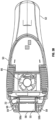
- FIG. 3c a cross-sectional view is taken on an axis substantially perpendicular to the view of Figure 3b .
- the charger circuit (26) controls circuit (28) mounted onto a printed circuit board, lamp (22), filter (68) and light output aperture (56).
- a reflector (70) for reflecting the pulse of optical radiation is accommodated within the handle portion (52) of the housing (50) is the energy storage device comprising a capacitor (20).
- the handle defines an opening (72) for mains power input.
- the housing (50) as a whole may be stored on a docking station or support as appropriate not shown in the Figures.
- the apparatus effectively functions in two modes, a sensing mode and a treatment mode, and the control circuit (28) is configured to enable switching between the two modes.
- a standby or ready user operable input (74) is provided to ready the apparatus for the user in a sensing mode.
- sensors (59) as represented, for example, in Figure 2b for sensing a measurable skin parameter such as a tone or colour of the skin to be treated. Alternative or additional skin parameters may be sensed.
- the sensor (59) includes a transmitter arranged to transmit sensing radiation through the sensor window (58a, 58b) onto the skin to be treated.
- the sensor (59) further includes a receiver such as a photodiode arranged to receive radiation reflected from a skin surface.
- Intensity of the received radiation is found to be representative of the tone of the skin, for example a light skin tone will reflect more than a dark skin tone.
- the intensity of the received radiation can be processed by the control circuit (28) using a processor provided thereby and compares the intensity with a calibrated set of intensity measurements to determine a sensed skin tone, which is then stored in a memory of the control circuit.
- the treatment light pulse energy then outputted to the skin is dependent on the sensed skin tone thus ensuring optimised treatment.
- An indicator (64) is preferably provided in the form of a visual display representative of the sensor measurement and/or the treatment energy dose. This may be in the form of a plurality of light indicators which are lit where the number of lights on represents the intensity of energy to be output.
- An important feature of the apparatus is the ability for a user to manually override the treatment energy dose determined on the basis of the sensor measurement. This is important in the event a user may find the treatment painful or ineffective and may therefore desire some manual control.
- a user input is therefore beneficially provided which causes adjustment to the determined treatment energy dose which is preferably carried out by the control system. This effectively changes the treatment energy dose which may be increased or decreased.
- the increase or decrease may be automatically determined or may be selected dependent on a body parameter such as location and actuation of the user input may reduce the treatment energy dose by a fixed value or percentage or alternatively may limit the maximum value of treatment energy dose.
- a user may select an intense mode which increases the output of the determined treatment energy dose by a predetermined amount.
- the indicator (64) provided on the apparatus indicates the selected mode of operation meaning that the beneficially visual indication shows that either intense or a gentle mode or operation has been selected.
- a skin treatment apparatus which provides improved accuracy in detection of the skin tone for the treatment area.
- the configuration of providing more than one sensor (59) provides the benefit that a cross-check is provided to ensure that there is accuracy of sensor functioning and further that the treatment area and the skin tone thereof is accurately reflected in the skin tone determined by the sensors.
- the sensors are provided adjacent the light output aperture (56) which means that the sensors are not impeded or affected by the high energy intense pulsed light treatment.
- the sensors (59) are disposed either side of the light output aperture (56) of the skin contact element (54) and each sensor (59) independently records the skin tone.
- the processor in the control circuit is configured to determine whether a valid skin tone reading has been achieved.
- the two skin tone measurements can also be used in determining the safest or best treatment setting to be used.
- the safest treatment setting would be based on the lowest skin tone measurement from the two sensors. Alternatively the highest measurement, the average or another calculation could be used. It will further be appreciated that additional sensors may be provided to improve accuracy of the determined skin tone of the treatment area.
- Figure 4a shows in block diagram form components utilising an embodiment falling outside the present invention.
- the diagram is similar to the diagram of Figure 1a , and like components has been identified with the same reference numerals.
- a discharge control element (80) such as an electronic switch (e.g. Mosfet) which may be provided in a flash pulse termination circuit as identified in the block diagram which is arranged to terminate discharge energy from the energy storage device (20) to the flashlamp (22).
- a discharge control element (80) in the flash pulse termination circuit (80) is that the light output pulse shape as shown in Figure 4c can be terminated in order that a desired energy output is achieved.
- the voltage of the energy storage device is 330 volts, however, the energy output for each of the three light output pulse shapes is different dependent on when, over time, the energy output from the energy storage device (20) is terminated.
- the first graph represents no termination of the energy from the energy storage device (20) and as such the energy output of 6J/cm 2 for a capacitor voltage of 300 volts is maximised.
- the second graph shows termination of the energy transferred from the energy storage device (20) meaning there is a reduced energy output of 4.5J/cm 2 .
- a third graph shows an earlier termination where the energy is 3.6J/cm 2 .
- the energy output is being controlled irrespective of the initial voltage of the energy storage device (20).
- the energy storage device (20) can be charged independently of the sensor or sensors output, so can be charged at the same time as the sensor(s) are recording skin tone. As there is no requirement to reduce the charge on the charge storage device (20), there is no associated time delay.
- the device is switched on and at T1 a user input causes activation of the apparatus.
- Sensor measurements are recorded and at T1 the energy storage device (20) is charged to a predetermined minimum voltage. This is maintained at time T2 until a user input through the trigger button actuates the apparatus.
- the energy storage device is boosted and at this time the voltage increases and the energy storage device is charged.
- the light is output as a pulse and the voltage of the energy storage device (20) drops.
Landscapes
- Health & Medical Sciences (AREA)
- Life Sciences & Earth Sciences (AREA)
- Engineering & Computer Science (AREA)
- Biomedical Technology (AREA)
- Public Health (AREA)
- Nuclear Medicine, Radiotherapy & Molecular Imaging (AREA)
- Veterinary Medicine (AREA)
- Animal Behavior & Ethology (AREA)
- General Health & Medical Sciences (AREA)
- Surgery (AREA)
- Pathology (AREA)
- Radiology & Medical Imaging (AREA)
- Physics & Mathematics (AREA)
- Biophysics (AREA)
- Electromagnetism (AREA)
- Otolaryngology (AREA)
- Heart & Thoracic Surgery (AREA)
- Medical Informatics (AREA)
- Molecular Biology (AREA)
- Optics & Photonics (AREA)
- Radiation-Therapy Devices (AREA)
- Cosmetics (AREA)
Priority Applications (2)
| Application Number | Priority Date | Filing Date | Title |
|---|---|---|---|
| EP20208207.9A EP3799820B1 (en) | 2013-12-04 | 2014-12-04 | Skin treatment apparatus utilising intense pulsed light (ipl) |
| EP18154104.6A EP3348223B1 (en) | 2013-12-04 | 2014-12-04 | Skin treatment apparatus utilising intense pulsed light (ipl) |
Applications Claiming Priority (2)
| Application Number | Priority Date | Filing Date | Title |
|---|---|---|---|
| GB1321382.2A GB2526764B (en) | 2013-12-04 | 2013-12-04 | Skin treatment apparatus utilising intense pulsed light (IPL) |
| PCT/GB2014/053609 WO2015082928A2 (en) | 2013-12-04 | 2014-12-04 | Skin treatment apparatus utilising intense pulsed light (ipl) |
Related Child Applications (4)
| Application Number | Title | Priority Date | Filing Date |
|---|---|---|---|
| EP20208207.9A Division EP3799820B1 (en) | 2013-12-04 | 2014-12-04 | Skin treatment apparatus utilising intense pulsed light (ipl) |
| EP20208207.9A Division-Into EP3799820B1 (en) | 2013-12-04 | 2014-12-04 | Skin treatment apparatus utilising intense pulsed light (ipl) |
| EP18154104.6A Division-Into EP3348223B1 (en) | 2013-12-04 | 2014-12-04 | Skin treatment apparatus utilising intense pulsed light (ipl) |
| EP18154104.6A Division EP3348223B1 (en) | 2013-12-04 | 2014-12-04 | Skin treatment apparatus utilising intense pulsed light (ipl) |
Publications (3)
| Publication Number | Publication Date |
|---|---|
| EP3076890A2 EP3076890A2 (en) | 2016-10-12 |
| EP3076890B1 EP3076890B1 (en) | 2018-01-31 |
| EP3076890B2 true EP3076890B2 (en) | 2025-03-05 |
Family
ID=49979769
Family Applications (3)
| Application Number | Title | Priority Date | Filing Date |
|---|---|---|---|
| EP14809688.6A Active EP3076890B2 (en) | 2013-12-04 | 2014-12-04 | Skin treatment apparatus utilising intense pulsed light (ipl) |
| EP18154104.6A Active EP3348223B1 (en) | 2013-12-04 | 2014-12-04 | Skin treatment apparatus utilising intense pulsed light (ipl) |
| EP20208207.9A Active EP3799820B1 (en) | 2013-12-04 | 2014-12-04 | Skin treatment apparatus utilising intense pulsed light (ipl) |
Family Applications After (2)
| Application Number | Title | Priority Date | Filing Date |
|---|---|---|---|
| EP18154104.6A Active EP3348223B1 (en) | 2013-12-04 | 2014-12-04 | Skin treatment apparatus utilising intense pulsed light (ipl) |
| EP20208207.9A Active EP3799820B1 (en) | 2013-12-04 | 2014-12-04 | Skin treatment apparatus utilising intense pulsed light (ipl) |
Country Status (5)
| Country | Link |
|---|---|
| US (2) | US10595939B2 (enExample) |
| EP (3) | EP3076890B2 (enExample) |
| JP (1) | JP6535343B2 (enExample) |
| GB (2) | GB2526764B (enExample) |
| WO (1) | WO2015082928A2 (enExample) |
Families Citing this family (31)
| Publication number | Priority date | Publication date | Assignee | Title |
|---|---|---|---|---|
| KR20170041291A (ko) | 2014-08-11 | 2017-04-14 | 더 보오드 오브 트러스티스 오브 더 유니버시티 오브 일리노이즈 | 생체 유체의 상피 묘사를 위한 장치 및 관련 방법 |
| USD901028S1 (en) * | 2016-06-11 | 2020-11-03 | Advino Technologies Llp | Laser therapy device |
| US10653342B2 (en) * | 2016-06-17 | 2020-05-19 | The Board Of Trustees Of The University Of Illinois | Soft, wearable microfluidic systems capable of capture, storage, and sensing of biofluids |
| CN106345066B (zh) * | 2016-10-11 | 2019-05-21 | 深圳可思美科技有限公司 | Ipl脱毛仪 |
| KR101951468B1 (ko) * | 2016-11-14 | 2019-02-22 | (주)미린트 | 비염치료기 및 비염치료기 제어방법 |
| USD791336S1 (en) * | 2016-11-30 | 2017-07-04 | Shenzhen Peninsula Medical Co., Ltd. | Ultraviolet treatment apparatus |
| USD812745S1 (en) * | 2017-01-19 | 2018-03-13 | Tweezerman International, Llc | Dermaplaner |
| ES2860276T3 (es) | 2017-08-01 | 2021-10-04 | Braun Gmbh | Dispositivo de depilación a base de luz y método de eliminación cosmética de vello |
| KR20190044560A (ko) | 2017-10-20 | 2019-04-30 | 주식회사 씨엠랩 | 고출력 led 장치 |
| CN109157747A (zh) * | 2017-10-30 | 2019-01-08 | 武汉奇致激光技术股份有限公司 | 一种强脉冲光治疗机的脉冲串输出控制方法 |
| CN108650757B (zh) * | 2018-03-28 | 2019-08-20 | 深圳可思美科技有限公司 | 一种脱毛仪 |
| EP3613376A1 (en) * | 2018-08-21 | 2020-02-26 | Koninklijke Philips N.V. | A handheld device for performing a treatment operation on skin |
| CN109603012A (zh) * | 2018-11-23 | 2019-04-12 | 北京镭特医疗科技有限公司 | 一种联合使用ipl和e光进行美容的方法 |
| CN110368594A (zh) * | 2019-06-26 | 2019-10-25 | 木马电器科技(东莞)有限责任公司 | 一种手持式光祛斑设备及祛斑方法 |
| KR102033783B1 (ko) | 2019-08-30 | 2019-10-17 | 조현철 | 헬멧 및 사용자단말기를 이용한 탈모예방 및 양모 장치 |
| CN112807567A (zh) * | 2019-11-18 | 2021-05-18 | 广州星际悦动股份有限公司 | 脱毛仪发光控制系统及方法 |
| CN112558528B (zh) * | 2020-12-18 | 2025-02-18 | 深圳罗马仕科技有限公司 | 脱毛仪器及其控制方法和脱毛仪设备 |
| JP7557740B2 (ja) * | 2021-02-05 | 2024-09-30 | パナソニックIpマネジメント株式会社 | 光照射式脱毛装置 |
| GB2604876B (en) * | 2021-03-15 | 2025-06-25 | Ipulse Ltd | Skin treatment device |
| US20220339460A1 (en) * | 2021-04-21 | 2022-10-27 | Archimedes Innovations, Pbc | Therapy system |
| CN113398490B (zh) * | 2021-06-24 | 2022-08-02 | 赣南医学院第一附属医院 | 一种脉冲激光美容治疗仪 |
| CN114343838B (zh) * | 2021-12-31 | 2024-06-25 | 广州星际悦动股份有限公司 | 脱毛仪的脉冲光控制方法、电路、设备及脱毛仪 |
| EP4299027A1 (en) | 2022-06-28 | 2024-01-03 | Koninklijke Philips N.V. | Hair treatment device |
| EP4385443A1 (en) * | 2022-12-15 | 2024-06-19 | Koninklijke Philips N.V. | Intense pulse light skin or hair care device |
| USD1053454S1 (en) * | 2023-02-02 | 2024-12-03 | Silkn Beauty Ltd | Hair removal device |
| GB2626956A (en) * | 2023-02-08 | 2024-08-14 | Ipulse Ltd | Skin treatment device |
| JP1789738S (ja) * | 2023-08-08 | 2025-01-23 | 皮膚治療機器 | |
| EP4545032A1 (en) * | 2023-10-26 | 2025-04-30 | Koninklijke Philips N.V. | A device for hair removal or treatment of skin |
| USD1026320S1 (en) * | 2023-12-18 | 2024-05-07 | Hui XI | Hair removal device |
| GR1010960B (el) * | 2024-06-10 | 2025-05-29 | Grigorii Petrovich GRABOVOI | Συσκευη αναπτυξης της συγκεντρωσης που αποτελειται απο τρεις λειτουργιες και μια μεθοδο υλοποιημενη σε υπολογιστη που χρησιμοποιειται στο ιδιο |
| USD1067518S1 (en) * | 2024-12-30 | 2025-03-18 | One Beauty Technology Co., Ltd. | Hair removal device |
Citations (10)
| Publication number | Priority date | Publication date | Assignee | Title |
|---|---|---|---|---|
| US4853600A (en) † | 1986-04-11 | 1989-08-01 | Urs Zeltner | Flash apparatus with color temperature control |
| US5720772A (en) † | 1992-10-20 | 1998-02-24 | Esc Medical Systems Ltd. | Method and apparatus for therapeutic electromagnetic treatment |
| EP0885629A2 (en) † | 1997-06-16 | 1998-12-23 | Danish Dermatologic Development A/S | Light pulse generating apparatus and cosmetic and therapeutic phototreatment |
| US5885274A (en) † | 1997-06-24 | 1999-03-23 | New Star Lasers, Inc. | Filament lamp for dermatological treatment |
| US6273883B1 (en) † | 1996-04-09 | 2001-08-14 | Cynosure, Inc. | Alexandrite laser system for treatment of dermatological specimens |
| WO2002085229A2 (en) † | 2001-04-20 | 2002-10-31 | Koninklijke Philips Electronics N.V. | Skin treating device with protection against radiation pulse overdose |
| WO2005015291A2 (en) † | 2003-08-12 | 2005-02-17 | Lumenis Ltd. | Method and system for controlling non-coherent pulsed light |
| WO2012056340A1 (en) † | 2010-10-25 | 2012-05-03 | Koninklijke Philips Electronics N.V. | Skin treatment system. |
| GB2496895A (en) † | 2011-11-25 | 2013-05-29 | Cyden Ltd | Skin treatment apparatus |
| WO2013173516A1 (en) † | 2012-05-15 | 2013-11-21 | Tria Beauty, Inc. | Dermatological treatment device with real-time energy control |
Family Cites Families (14)
| Publication number | Priority date | Publication date | Assignee | Title |
|---|---|---|---|---|
| IL122840A (en) | 1997-12-31 | 2002-04-21 | Radiancy Inc | Hair removal device and methods |
| JP4141260B2 (ja) | 2001-03-30 | 2008-08-27 | コーニンクレッカ フィリップス エレクトロニクス エヌ ヴィ | 保護された放射出力開口を有する皮膚処理装置 |
| GB2381752A (en) * | 2001-11-06 | 2003-05-14 | Ezio Panzeri | Laser skin treatment device with control means dependent on a sensed property of the skin to be treated |
| US8709003B2 (en) * | 2003-02-25 | 2014-04-29 | Tria Beauty, Inc. | Capacitive sensing method and device for detecting skin |
| EP1596744B1 (en) * | 2003-02-25 | 2016-02-17 | Tria Beauty, Inc. | Self-contained, eye-safe hair-regrowth-inhibition apparatus and method |
| ES2401145T3 (es) | 2003-08-18 | 2013-04-17 | Koninklijke Philips Electronics N.V. | Dispositivo para el control óptico de baja intensidad del crecimiento de vello |
| US20070239144A1 (en) | 2006-04-06 | 2007-10-11 | Lite Touch Ltd. | Methods of photothermolysis |
| US20080058782A1 (en) * | 2006-08-29 | 2008-03-06 | Reliant Technologies, Inc. | Method and apparatus for monitoring and controlling density of fractional tissue treatments |
| US20080140164A1 (en) * | 2006-12-06 | 2008-06-12 | Clrs Technology Corporation | Light emitting therapeutic devices and methods |
| EP2254496B1 (en) * | 2008-03-21 | 2014-01-15 | Koninklijke Philips N.V. | Hair removal system |
| KR101727095B1 (ko) * | 2009-07-20 | 2017-05-02 | 코닌클리케 필립스 엔.브이. | 피사체에 광을 조사하는 광 조사 장치 |
| US20120232538A1 (en) | 2011-02-03 | 2012-09-13 | Tria Beauty, Inc. | Radiation-based dermatological devices and methods |
| EP2499985A1 (en) * | 2011-03-14 | 2012-09-19 | Koninklijke Philips Electronics N.V. | Light based skin care device with controllable fluency level |
| JP6437181B2 (ja) * | 2012-03-19 | 2018-12-12 | 株式会社ジェイ クラフト | 制毛・脱毛装置 |
-
2013
- 2013-12-04 GB GB1321382.2A patent/GB2526764B/en active Active
- 2013-12-04 GB GB2012396.4A patent/GB2583683B/en active Active
-
2014
- 2014-12-04 WO PCT/GB2014/053609 patent/WO2015082928A2/en not_active Ceased
- 2014-12-04 EP EP14809688.6A patent/EP3076890B2/en active Active
- 2014-12-04 EP EP18154104.6A patent/EP3348223B1/en active Active
- 2014-12-04 JP JP2016557201A patent/JP6535343B2/ja active Active
- 2014-12-04 EP EP20208207.9A patent/EP3799820B1/en active Active
- 2014-12-04 US US15/101,102 patent/US10595939B2/en active Active
-
2020
- 2020-02-18 US US16/793,517 patent/US11337754B2/en active Active
Patent Citations (10)
| Publication number | Priority date | Publication date | Assignee | Title |
|---|---|---|---|---|
| US4853600A (en) † | 1986-04-11 | 1989-08-01 | Urs Zeltner | Flash apparatus with color temperature control |
| US5720772A (en) † | 1992-10-20 | 1998-02-24 | Esc Medical Systems Ltd. | Method and apparatus for therapeutic electromagnetic treatment |
| US6273883B1 (en) † | 1996-04-09 | 2001-08-14 | Cynosure, Inc. | Alexandrite laser system for treatment of dermatological specimens |
| EP0885629A2 (en) † | 1997-06-16 | 1998-12-23 | Danish Dermatologic Development A/S | Light pulse generating apparatus and cosmetic and therapeutic phototreatment |
| US5885274A (en) † | 1997-06-24 | 1999-03-23 | New Star Lasers, Inc. | Filament lamp for dermatological treatment |
| WO2002085229A2 (en) † | 2001-04-20 | 2002-10-31 | Koninklijke Philips Electronics N.V. | Skin treating device with protection against radiation pulse overdose |
| WO2005015291A2 (en) † | 2003-08-12 | 2005-02-17 | Lumenis Ltd. | Method and system for controlling non-coherent pulsed light |
| WO2012056340A1 (en) † | 2010-10-25 | 2012-05-03 | Koninklijke Philips Electronics N.V. | Skin treatment system. |
| GB2496895A (en) † | 2011-11-25 | 2013-05-29 | Cyden Ltd | Skin treatment apparatus |
| WO2013173516A1 (en) † | 2012-05-15 | 2013-11-21 | Tria Beauty, Inc. | Dermatological treatment device with real-time energy control |
Also Published As
| Publication number | Publication date |
|---|---|
| WO2015082928A2 (en) | 2015-06-11 |
| EP3799820A1 (en) | 2021-04-07 |
| US10595939B2 (en) | 2020-03-24 |
| US11337754B2 (en) | 2022-05-24 |
| GB202012396D0 (en) | 2020-09-23 |
| GB2583683A (en) | 2020-11-04 |
| EP3799820B1 (en) | 2022-06-08 |
| US20160374758A1 (en) | 2016-12-29 |
| EP3076890B1 (en) | 2018-01-31 |
| JP6535343B2 (ja) | 2019-06-26 |
| GB2526764A (en) | 2015-12-09 |
| GB2583683B (en) | 2021-03-31 |
| WO2015082928A3 (en) | 2015-07-30 |
| EP3076890A2 (en) | 2016-10-12 |
| EP3348223A2 (en) | 2018-07-18 |
| EP3348223B1 (en) | 2020-12-16 |
| GB201321382D0 (en) | 2014-01-15 |
| JP2016539777A (ja) | 2016-12-22 |
| EP3348223A3 (en) | 2018-11-14 |
| GB2526764B (en) | 2020-10-07 |
| US20200179048A1 (en) | 2020-06-11 |
Similar Documents
| Publication | Publication Date | Title |
|---|---|---|
| US11337754B2 (en) | Skin treatment apparatus utilising intense pulsed light (IPL) | |
| US6976984B2 (en) | Skin treating device comprising a protected radiation exit opening | |
| US6955672B2 (en) | Skin treating device with protection against radiation pulse overdose | |
| EP2895096B1 (en) | Device for dermatological use with a failsafe control | |
| US20140039473A1 (en) | Dermatological Treatment Device With Real-Time Energy Control | |
| GB2604876A (en) | Skin treatment device | |
| US20060151709A1 (en) | Device and method for determining an allowed expsure of human skin to uv radiation | |
| RU2406548C1 (ru) | Устройство регулирования роста волос | |
| EP1384446A1 (en) | Hand-held laser for skin treatment | |
| EP2499985A1 (en) | Light based skin care device with controllable fluency level | |
| GB2580571A (en) | Skin treatment apparatus utilsing intense pulsed light (IPL) | |
| EP3534831A1 (en) | Dental curing light | |
| WO2012011009A1 (en) | Improvements in phototherapy | |
| KR20250123852A (ko) | 고강도 펄스 광 피부 또는 모발 케어 장치 | |
| WO2024147003A1 (en) | Skin treatment apparatus | |
| JP2026503884A (ja) | 皮膚治療器具 | |
| GB2470927A (en) | Phototherapy apparatus with skin temperature control |
Legal Events
| Date | Code | Title | Description |
|---|---|---|---|
| PUAI | Public reference made under article 153(3) epc to a published international application that has entered the european phase |
Free format text: ORIGINAL CODE: 0009012 |
|
| 17P | Request for examination filed |
Effective date: 20160523 |
|
| AK | Designated contracting states |
Kind code of ref document: A2 Designated state(s): AL AT BE BG CH CY CZ DE DK EE ES FI FR GB GR HR HU IE IS IT LI LT LU LV MC MK MT NL NO PL PT RO RS SE SI SK SM TR |
|
| AX | Request for extension of the european patent |
Extension state: BA ME |
|
| DAX | Request for extension of the european patent (deleted) | ||
| GRAP | Despatch of communication of intention to grant a patent |
Free format text: ORIGINAL CODE: EPIDOSNIGR1 |
|
| STAA | Information on the status of an ep patent application or granted ep patent |
Free format text: STATUS: GRANT OF PATENT IS INTENDED |
|
| INTG | Intention to grant announced |
Effective date: 20170912 |
|
| GRAS | Grant fee paid |
Free format text: ORIGINAL CODE: EPIDOSNIGR3 |
|
| GRAA | (expected) grant |
Free format text: ORIGINAL CODE: 0009210 |
|
| STAA | Information on the status of an ep patent application or granted ep patent |
Free format text: STATUS: THE PATENT HAS BEEN GRANTED |
|
| AK | Designated contracting states |
Kind code of ref document: B1 Designated state(s): AL AT BE BG CH CY CZ DE DK EE ES FI FR GB GR HR HU IE IS IT LI LT LU LV MC MK MT NL NO PL PT RO RS SE SI SK SM TR |
|
| REG | Reference to a national code |
Ref country code: GB Ref legal event code: FG4D Ref country code: CH Ref legal event code: EP |
|
| REG | Reference to a national code |
Ref country code: AT Ref legal event code: REF Ref document number: 966638 Country of ref document: AT Kind code of ref document: T Effective date: 20180215 |
|
| REG | Reference to a national code |
Ref country code: IE Ref legal event code: FG4D |
|
| REG | Reference to a national code |
Ref country code: DE Ref legal event code: R096 Ref document number: 602014020562 Country of ref document: DE |
|
| REG | Reference to a national code |
Ref country code: NL Ref legal event code: MP Effective date: 20180131 |
|
| REG | Reference to a national code |
Ref country code: LT Ref legal event code: MG4D |
|
| REG | Reference to a national code |
Ref country code: AT Ref legal event code: MK05 Ref document number: 966638 Country of ref document: AT Kind code of ref document: T Effective date: 20180131 |
|
| PG25 | Lapsed in a contracting state [announced via postgrant information from national office to epo] |
Ref country code: FI Free format text: LAPSE BECAUSE OF FAILURE TO SUBMIT A TRANSLATION OF THE DESCRIPTION OR TO PAY THE FEE WITHIN THE PRESCRIBED TIME-LIMIT Effective date: 20180131 Ref country code: HR Free format text: LAPSE BECAUSE OF FAILURE TO SUBMIT A TRANSLATION OF THE DESCRIPTION OR TO PAY THE FEE WITHIN THE PRESCRIBED TIME-LIMIT Effective date: 20180131 Ref country code: LT Free format text: LAPSE BECAUSE OF FAILURE TO SUBMIT A TRANSLATION OF THE DESCRIPTION OR TO PAY THE FEE WITHIN THE PRESCRIBED TIME-LIMIT Effective date: 20180131 Ref country code: NO Free format text: LAPSE BECAUSE OF FAILURE TO SUBMIT A TRANSLATION OF THE DESCRIPTION OR TO PAY THE FEE WITHIN THE PRESCRIBED TIME-LIMIT Effective date: 20180430 Ref country code: ES Free format text: LAPSE BECAUSE OF FAILURE TO SUBMIT A TRANSLATION OF THE DESCRIPTION OR TO PAY THE FEE WITHIN THE PRESCRIBED TIME-LIMIT Effective date: 20180131 Ref country code: NL Free format text: LAPSE BECAUSE OF FAILURE TO SUBMIT A TRANSLATION OF THE DESCRIPTION OR TO PAY THE FEE WITHIN THE PRESCRIBED TIME-LIMIT Effective date: 20180131 |
|
| PG25 | Lapsed in a contracting state [announced via postgrant information from national office to epo] |
Ref country code: BG Free format text: LAPSE BECAUSE OF FAILURE TO SUBMIT A TRANSLATION OF THE DESCRIPTION OR TO PAY THE FEE WITHIN THE PRESCRIBED TIME-LIMIT Effective date: 20180430 Ref country code: RS Free format text: LAPSE BECAUSE OF FAILURE TO SUBMIT A TRANSLATION OF THE DESCRIPTION OR TO PAY THE FEE WITHIN THE PRESCRIBED TIME-LIMIT Effective date: 20180131 Ref country code: IS Free format text: LAPSE BECAUSE OF FAILURE TO SUBMIT A TRANSLATION OF THE DESCRIPTION OR TO PAY THE FEE WITHIN THE PRESCRIBED TIME-LIMIT Effective date: 20180531 Ref country code: SE Free format text: LAPSE BECAUSE OF FAILURE TO SUBMIT A TRANSLATION OF THE DESCRIPTION OR TO PAY THE FEE WITHIN THE PRESCRIBED TIME-LIMIT Effective date: 20180131 Ref country code: LV Free format text: LAPSE BECAUSE OF FAILURE TO SUBMIT A TRANSLATION OF THE DESCRIPTION OR TO PAY THE FEE WITHIN THE PRESCRIBED TIME-LIMIT Effective date: 20180131 Ref country code: AT Free format text: LAPSE BECAUSE OF FAILURE TO SUBMIT A TRANSLATION OF THE DESCRIPTION OR TO PAY THE FEE WITHIN THE PRESCRIBED TIME-LIMIT Effective date: 20180131 Ref country code: PL Free format text: LAPSE BECAUSE OF FAILURE TO SUBMIT A TRANSLATION OF THE DESCRIPTION OR TO PAY THE FEE WITHIN THE PRESCRIBED TIME-LIMIT Effective date: 20180131 Ref country code: GR Free format text: LAPSE BECAUSE OF FAILURE TO SUBMIT A TRANSLATION OF THE DESCRIPTION OR TO PAY THE FEE WITHIN THE PRESCRIBED TIME-LIMIT Effective date: 20180501 |
|
| RAP2 | Party data changed (patent owner data changed or rights of a patent transferred) |
Owner name: IPULSE LIMITED |
|
| REG | Reference to a national code |
Ref country code: DE Ref legal event code: R026 Ref document number: 602014020562 Country of ref document: DE |
|
| PG25 | Lapsed in a contracting state [announced via postgrant information from national office to epo] |
Ref country code: EE Free format text: LAPSE BECAUSE OF FAILURE TO SUBMIT A TRANSLATION OF THE DESCRIPTION OR TO PAY THE FEE WITHIN THE PRESCRIBED TIME-LIMIT Effective date: 20180131 Ref country code: AL Free format text: LAPSE BECAUSE OF FAILURE TO SUBMIT A TRANSLATION OF THE DESCRIPTION OR TO PAY THE FEE WITHIN THE PRESCRIBED TIME-LIMIT Effective date: 20180131 Ref country code: RO Free format text: LAPSE BECAUSE OF FAILURE TO SUBMIT A TRANSLATION OF THE DESCRIPTION OR TO PAY THE FEE WITHIN THE PRESCRIBED TIME-LIMIT Effective date: 20180131 |
|
| PLBI | Opposition filed |
Free format text: ORIGINAL CODE: 0009260 |
|
| PLAX | Notice of opposition and request to file observation + time limit sent |
Free format text: ORIGINAL CODE: EPIDOSNOBS2 |
|
| PG25 | Lapsed in a contracting state [announced via postgrant information from national office to epo] |
Ref country code: CZ Free format text: LAPSE BECAUSE OF FAILURE TO SUBMIT A TRANSLATION OF THE DESCRIPTION OR TO PAY THE FEE WITHIN THE PRESCRIBED TIME-LIMIT Effective date: 20180131 Ref country code: SK Free format text: LAPSE BECAUSE OF FAILURE TO SUBMIT A TRANSLATION OF THE DESCRIPTION OR TO PAY THE FEE WITHIN THE PRESCRIBED TIME-LIMIT Effective date: 20180131 Ref country code: SM Free format text: LAPSE BECAUSE OF FAILURE TO SUBMIT A TRANSLATION OF THE DESCRIPTION OR TO PAY THE FEE WITHIN THE PRESCRIBED TIME-LIMIT Effective date: 20180131 Ref country code: DK Free format text: LAPSE BECAUSE OF FAILURE TO SUBMIT A TRANSLATION OF THE DESCRIPTION OR TO PAY THE FEE WITHIN THE PRESCRIBED TIME-LIMIT Effective date: 20180131 |
|
| 26 | Opposition filed |
Opponent name: SPECTRUM BRANDS, INC. Effective date: 20181030 |
|
| PG25 | Lapsed in a contracting state [announced via postgrant information from national office to epo] |
Ref country code: SI Free format text: LAPSE BECAUSE OF FAILURE TO SUBMIT A TRANSLATION OF THE DESCRIPTION OR TO PAY THE FEE WITHIN THE PRESCRIBED TIME-LIMIT Effective date: 20180131 |
|
| PLBB | Reply of patent proprietor to notice(s) of opposition received |
Free format text: ORIGINAL CODE: EPIDOSNOBS3 |
|
| REG | Reference to a national code |
Ref country code: CH Ref legal event code: PL |
|
| PG25 | Lapsed in a contracting state [announced via postgrant information from national office to epo] |
Ref country code: MC Free format text: LAPSE BECAUSE OF FAILURE TO SUBMIT A TRANSLATION OF THE DESCRIPTION OR TO PAY THE FEE WITHIN THE PRESCRIBED TIME-LIMIT Effective date: 20180131 Ref country code: LU Free format text: LAPSE BECAUSE OF NON-PAYMENT OF DUE FEES Effective date: 20181204 |
|
| REG | Reference to a national code |
Ref country code: IE Ref legal event code: MM4A |
|
| REG | Reference to a national code |
Ref country code: BE Ref legal event code: MM Effective date: 20181231 |
|
| PG25 | Lapsed in a contracting state [announced via postgrant information from national office to epo] |
Ref country code: IE Free format text: LAPSE BECAUSE OF NON-PAYMENT OF DUE FEES Effective date: 20181204 |
|
| PG25 | Lapsed in a contracting state [announced via postgrant information from national office to epo] |
Ref country code: BE Free format text: LAPSE BECAUSE OF NON-PAYMENT OF DUE FEES Effective date: 20181231 |
|
| PG25 | Lapsed in a contracting state [announced via postgrant information from national office to epo] |
Ref country code: CH Free format text: LAPSE BECAUSE OF NON-PAYMENT OF DUE FEES Effective date: 20181231 Ref country code: LI Free format text: LAPSE BECAUSE OF NON-PAYMENT OF DUE FEES Effective date: 20181231 |
|
| PG25 | Lapsed in a contracting state [announced via postgrant information from national office to epo] |
Ref country code: MT Free format text: LAPSE BECAUSE OF NON-PAYMENT OF DUE FEES Effective date: 20181204 |
|
| RDAF | Communication despatched that patent is revoked |
Free format text: ORIGINAL CODE: EPIDOSNREV1 |
|
| PG25 | Lapsed in a contracting state [announced via postgrant information from national office to epo] |
Ref country code: TR Free format text: LAPSE BECAUSE OF FAILURE TO SUBMIT A TRANSLATION OF THE DESCRIPTION OR TO PAY THE FEE WITHIN THE PRESCRIBED TIME-LIMIT Effective date: 20180131 |
|
| APBM | Appeal reference recorded |
Free format text: ORIGINAL CODE: EPIDOSNREFNO |
|
| APBP | Date of receipt of notice of appeal recorded |
Free format text: ORIGINAL CODE: EPIDOSNNOA2O |
|
| APAH | Appeal reference modified |
Free format text: ORIGINAL CODE: EPIDOSCREFNO |
|
| PG25 | Lapsed in a contracting state [announced via postgrant information from national office to epo] |
Ref country code: PT Free format text: LAPSE BECAUSE OF FAILURE TO SUBMIT A TRANSLATION OF THE DESCRIPTION OR TO PAY THE FEE WITHIN THE PRESCRIBED TIME-LIMIT Effective date: 20180131 |
|
| PG25 | Lapsed in a contracting state [announced via postgrant information from national office to epo] |
Ref country code: CY Free format text: LAPSE BECAUSE OF FAILURE TO SUBMIT A TRANSLATION OF THE DESCRIPTION OR TO PAY THE FEE WITHIN THE PRESCRIBED TIME-LIMIT Effective date: 20180131 Ref country code: MK Free format text: LAPSE BECAUSE OF NON-PAYMENT OF DUE FEES Effective date: 20180131 Ref country code: HU Free format text: LAPSE BECAUSE OF FAILURE TO SUBMIT A TRANSLATION OF THE DESCRIPTION OR TO PAY THE FEE WITHIN THE PRESCRIBED TIME-LIMIT; INVALID AB INITIO Effective date: 20141204 |
|
| APBQ | Date of receipt of statement of grounds of appeal recorded |
Free format text: ORIGINAL CODE: EPIDOSNNOA3O |
|
| P01 | Opt-out of the competence of the unified patent court (upc) registered |
Effective date: 20230429 |
|
| APBU | Appeal procedure closed |
Free format text: ORIGINAL CODE: EPIDOSNNOA9O |
|
| PLAY | Examination report in opposition despatched + time limit |
Free format text: ORIGINAL CODE: EPIDOSNORE2 |
|
| PLBC | Reply to examination report in opposition received |
Free format text: ORIGINAL CODE: EPIDOSNORE3 |
|
| PLAP | Information related to despatch of examination report in opposition + time limit deleted |
Free format text: ORIGINAL CODE: EPIDOSDORE2 |
|
| PLAT | Information related to reply to examination report in opposition deleted |
Free format text: ORIGINAL CODE: EPIDOSDORE3 |
|
| PLAY | Examination report in opposition despatched + time limit |
Free format text: ORIGINAL CODE: EPIDOSNORE2 |
|
| PGFP | Annual fee paid to national office [announced via postgrant information from national office to epo] |
Ref country code: IT Payment date: 20241218 Year of fee payment: 11 |
|
| PUAH | Patent maintained in amended form |
Free format text: ORIGINAL CODE: 0009272 |
|
| STAA | Information on the status of an ep patent application or granted ep patent |
Free format text: STATUS: PATENT MAINTAINED AS AMENDED |
|
| 27A | Patent maintained in amended form |
Effective date: 20250305 |
|
| AK | Designated contracting states |
Kind code of ref document: B2 Designated state(s): AL AT BE BG CH CY CZ DE DK EE ES FI FR GB GR HR HU IE IS IT LI LT LU LV MC MK MT NL NO PL PT RO RS SE SI SK SM TR |
|
| REG | Reference to a national code |
Ref country code: DE Ref legal event code: R102 Ref document number: 602014020562 Country of ref document: DE |
|
| PGFP | Annual fee paid to national office [announced via postgrant information from national office to epo] |
Ref country code: DE Payment date: 20241231 Year of fee payment: 11 |
|
| PGFP | Annual fee paid to national office [announced via postgrant information from national office to epo] |
Ref country code: GB Payment date: 20251223 Year of fee payment: 12 |
|
| PGFP | Annual fee paid to national office [announced via postgrant information from national office to epo] |
Ref country code: FR Payment date: 20251229 Year of fee payment: 12 |