EP3076542B2 - Lärmsteuerung für eine windturbine - Google Patents
Lärmsteuerung für eine windturbine Download PDFInfo
- Publication number
- EP3076542B2 EP3076542B2 EP15162469.9A EP15162469A EP3076542B2 EP 3076542 B2 EP3076542 B2 EP 3076542B2 EP 15162469 A EP15162469 A EP 15162469A EP 3076542 B2 EP3076542 B2 EP 3076542B2
- Authority
- EP
- European Patent Office
- Prior art keywords
- noise
- component
- vibration
- generator
- wind turbine
- Prior art date
- Legal status (The legal status is an assumption and is not a legal conclusion. Google has not performed a legal analysis and makes no representation as to the accuracy of the status listed.)
- Active
Links
Images

Classifications
-
- F—MECHANICAL ENGINEERING; LIGHTING; HEATING; WEAPONS; BLASTING
- F03—MACHINES OR ENGINES FOR LIQUIDS; WIND, SPRING, OR WEIGHT MOTORS; PRODUCING MECHANICAL POWER OR A REACTIVE PROPULSIVE THRUST, NOT OTHERWISE PROVIDED FOR
- F03D—WIND MOTORS
- F03D7/00—Controlling wind motors
- F03D7/02—Controlling wind motors the wind motors having rotation axis substantially parallel to the air flow entering the rotor
- F03D7/0296—Controlling wind motors the wind motors having rotation axis substantially parallel to the air flow entering the rotor to prevent, counteract or reduce noise emissions
-
- F—MECHANICAL ENGINEERING; LIGHTING; HEATING; WEAPONS; BLASTING
- F03—MACHINES OR ENGINES FOR LIQUIDS; WIND, SPRING, OR WEIGHT MOTORS; PRODUCING MECHANICAL POWER OR A REACTIVE PROPULSIVE THRUST, NOT OTHERWISE PROVIDED FOR
- F03D—WIND MOTORS
- F03D9/00—Adaptations of wind motors for special use; Combinations of wind motors with apparatus driven thereby; Wind motors specially adapted for installation in particular locations
- F03D9/20—Wind motors characterised by the driven apparatus
- F03D9/25—Wind motors characterised by the driven apparatus the apparatus being an electrical generator
- F03D9/255—Wind motors characterised by the driven apparatus the apparatus being an electrical generator connected to electrical distribution networks; Arrangements therefor
-
- H—ELECTRICITY
- H02—GENERATION; CONVERSION OR DISTRIBUTION OF ELECTRIC POWER
- H02P—CONTROL OR REGULATION OF ELECTRIC MOTORS, ELECTRIC GENERATORS OR DYNAMO-ELECTRIC CONVERTERS; CONTROLLING TRANSFORMERS, REACTORS OR CHOKE COILS
- H02P21/00—Arrangements or methods for the control of electric machines by vector control, e.g. by control of field orientation
- H02P21/22—Current control, e.g. using a current control loop
-
- H—ELECTRICITY
- H02—GENERATION; CONVERSION OR DISTRIBUTION OF ELECTRIC POWER
- H02P—CONTROL OR REGULATION OF ELECTRIC MOTORS, ELECTRIC GENERATORS OR DYNAMO-ELECTRIC CONVERTERS; CONTROLLING TRANSFORMERS, REACTORS OR CHOKE COILS
- H02P29/00—Arrangements for regulating or controlling electric motors, appropriate for both AC and DC motors
- H02P29/50—Reduction of harmonics
-
- H—ELECTRICITY
- H02—GENERATION; CONVERSION OR DISTRIBUTION OF ELECTRIC POWER
- H02P—CONTROL OR REGULATION OF ELECTRIC MOTORS, ELECTRIC GENERATORS OR DYNAMO-ELECTRIC CONVERTERS; CONTROLLING TRANSFORMERS, REACTORS OR CHOKE COILS
- H02P6/00—Arrangements for controlling synchronous motors or other dynamo-electric motors using electronic commutation dependent on the rotor position; Electronic commutators therefor
- H02P6/14—Electronic commutators
- H02P6/16—Circuit arrangements for detecting position
- H02P6/18—Circuit arrangements for detecting position without separate position detecting elements
- H02P6/183—Circuit arrangements for detecting position without separate position detecting elements using an injected high frequency signal
-
- H—ELECTRICITY
- H02—GENERATION; CONVERSION OR DISTRIBUTION OF ELECTRIC POWER
- H02P—CONTROL OR REGULATION OF ELECTRIC MOTORS, ELECTRIC GENERATORS OR DYNAMO-ELECTRIC CONVERTERS; CONTROLLING TRANSFORMERS, REACTORS OR CHOKE COILS
- H02P9/00—Arrangements for controlling electric generators for the purpose of obtaining a desired output
- H02P9/42—Arrangements for controlling electric generators for the purpose of obtaining a desired output to obtain desired frequency without varying speed of the generator
-
- Y—GENERAL TAGGING OF NEW TECHNOLOGICAL DEVELOPMENTS; GENERAL TAGGING OF CROSS-SECTIONAL TECHNOLOGIES SPANNING OVER SEVERAL SECTIONS OF THE IPC; TECHNICAL SUBJECTS COVERED BY FORMER USPC CROSS-REFERENCE ART COLLECTIONS [XRACs] AND DIGESTS
- Y02—TECHNOLOGIES OR APPLICATIONS FOR MITIGATION OR ADAPTATION AGAINST CLIMATE CHANGE
- Y02E—REDUCTION OF GREENHOUSE GAS [GHG] EMISSIONS, RELATED TO ENERGY GENERATION, TRANSMISSION OR DISTRIBUTION
- Y02E10/00—Energy generation through renewable energy sources
- Y02E10/70—Wind energy
- Y02E10/72—Wind turbines with rotation axis in wind direction
Definitions
- the present invention relates to an arrangement and a method for determining a d-component of a reference current, to a generator side controller for controlling a generator side frequency converter of a wind turbine (e.g. having a permanent magnet synchronous generator) and further to a wind turbine.
- a generator side controller for controlling a generator side frequency converter of a wind turbine (e.g. having a permanent magnet synchronous generator) and further to a wind turbine.
- EP 2 043 255 A2 discloses a system and method for controlling torque ripples in synchronous machines, wherein power and/or torque control signals are provided to the power converter to regulate the fundamental power and/or torque produced by the machine.
- EP 2 485 388 A1 discloses a method for controlling the operation of an electromechanical transducer, wherein a harmonic control signal is determined being indicative for a harmonic operational behavior of the electromechanical transducer, wherein the harmonic operational behavior is given by electric and/or mechanical oscillations having frequency components being different from a fundamental frequency. Further, a modified drive signal based on the determined harmonic control signal is generated and supplied to electromagnetic coils of a stator of the electromechanical transducer.
- a feedback control method with respect to the d-component of the current is proposed according to embodiments of the present invention, allowing the drive to operate at reduced noise and vibration levels.
- the arrangement and method may in particular be applicable to reduce noise and vibrations in permanent magnet synchronous generators by controlling the generator d-component of the current.
- Embodiments of the present invention may be applied or employed for wind turbine applications, but it may also be applied to other equipment with demanding noise/vibration requirements when employing permanent magnet synchronous machines.
- noise/vibration in different contexts may represent or mean noise and/or vibration.
- a noise control arrangement for determining a d-component of a reference current in a d-q coordinate system for reducing noise and/or vibration of a wind turbine, the arrangement comprising a noise/vibration determination module for determining noise/vibration components of oscillations of at least one wind turbine component, and a processing block for calculating a first type of the d-component of the reference current based on the noise/vibration component output by the noise/vibration determination module.
- the processing block comprises a noise/vibration processing module(such as e.g. performing signal processing) for obtaining an actual characteristic of at least one noise/vibration component of the determined noise/vibration components, a reference determination module (such as e.g. comprising or using a LUT) for providing a reference characteristic of the harmonic component, and a control module (e.g. a PI controller) for calculating a first type of the d-component of the reference current based on a difference between the actual characteristic and the reference characteristic of the noise/vibration component.
- a noise/vibration processing module such as e.g. performing signal processing
- a reference determination module such as e.g. comprising or using a LUT
- a control module e.g. a PI controller
- the arrangement may comprise hardware and/or software, in particular also including a (programmable) processor.
- a d-q coordinate system may be a system which rotates synchronously with the rotating rotor (or synchronously with an electrical rotation).
- the dqo transformation can be thought of in geometric terms as the projection of the three separate sinusoidal phase quantities onto two axes rotating with the same angular velocity as the sinusoidal phase quantities.
- the two axes are called the direct, or d, axis; and the quadrature or q, axis; that is, with the q-axis being at an angle of 90 degrees from the direct axis.
- the reference current may also comprise a q-component which may be determined by a conventional method.
- ⁇ is the rotor flux position.
- the d-axis is aligned with the rotor flux space vector, and Id allows for flux weakening. Iq may allow for torque control.
- the d-component and the q-component of the reference current may then be supplied to a current controller which may derive therefrom reference voltages which in turn may be supplied to a modulator module which may generate pulse width modulation signals to be supplied to gates of power transistors comprised in the generator side converter of the wind turbine frequency converter.
- the several modules (noise/vibration determination module, noise/vibration processing module, reference determination module, control module) of the arrangement may comprise hardware and/or software, in particular also including one or more processors and one or more electronic data storages.
- the noise/vibration determination module may determine noise/vibration components of oscillations (electrical and/or mechanical oscillations) of at least one wind turbine component (for example mechanical component and/or electronic/electric/magnetic component, in particular the generator) in a number of ways. Thereby, electrical and/or mechanical signals may be measured, sensed or calculated. Noise of the wind turbine (or at least one wind turbine component) may be associated with noise/vibration components or frequency components that are undesired, e.g. certain harmonics multiples of the generator electrical frequency.
- the noise/vibration processing module may process the noise/vibration components (for example represented by analog signals, such as sinusoidal wave traces, or digital data, such as amplitude and/or phase of the noise/vibration components).
- the characteristic of at least one noise/vibration component may for example comprise amplitude and/or phase of this particular vibration (or frequency) component.
- the noise/vibration processing module may also obtain the actual characteristics of several noise/vibration components of the determined noise/vibration components.
- the characteristic may also comprise a peak value of the corresponding noise/vibration component.
- the noise/vibration processing module may for example comprise a bandpass filter, a Fourier analysis module or a combination of the aforementioned functionalities.
- the reference determination module may be used to provide, for a particular noise/vibration component, an expected reference characteristic and may for example involve simulations and/or offline testing.
- the control module may eventually calculate the first type of the d-component of the reference current such that the difference between the actual characteristic and the reference characteristic of the noise/vibration component ideally vanishes.
- Different types of controllers may be employed for the control module, e.g. sliding mode controller or the like.
- a feedback control method and feedback control arrangement of I d i.e. the d-component of the current to be output by the generator of the wind turbine
- I d i.e. the d-component of the current to be output by the generator of the wind turbine
- the noise/vibration determination module comprises a sensor for sensing noise and/or vibration, in particular microphone and/or acceleration sensor, for measuring the noise/vibration components of oscillations of the at least one wind turbine component.
- the sensor may for example comprise an acoustic sensor, or an acceleration sensor, in particular installed at plural locations of the wind turbine or in particular installed at a nacelle of the wind turbine. Thereby, a reliable determination of the noise/vibration components of the oscillations may be provided.
- the noise/vibration determination module comprises an estimation module for estimating the noise/vibration components of oscillations of the at least one wind turbine component based on current, voltage output by a generator of the wind turbine and based on rotational frequency and angular position of a rotor of the generator.
- the estimation module may comprise an arithmetic/logic processor.
- the inputs of the estimation module may comprise electrical quantities of voltage and/or current output by the generator. Thereby, one or more sensors may be dispensed with.
- the arrangement may comprise a switch to selectively (alternatively) supplying the noise/vibration components of oscillations of the at least one wind turbine component as measured by the sensor or as estimated by the estimation module to the noise/vibration processing module.
- a switch to selectively (alternatively) supplying the noise/vibration components of oscillations of the at least one wind turbine component as measured by the sensor or as estimated by the estimation module to the noise/vibration processing module.
- the reference determination module is adapted to calculate the reference characteristic of the noise/vibration component based on a simulation or off-line test using a rotational frequency and a torque of the generator as input.
- a reference value or reference values may be essentially zero.
- an ideally operating wind turbine may generate unavoidable frequency components or noise/vibration components.
- a simulation in particular involving a physical/mechanical model of the wind turbine) may be required to obtain the reference characteristic of the one or more noise/vibration components.
- the reference determination module may comprise a look up table (LUT) which may comprise information for different working points (such as rotor frequency, torque and/or generator power).
- LUT look up table
- the noise/vibration processing module outputs an amplitude and/or phase of the noise/vibration component, in particular being associated with 6 times or 12 times an electrical frequency, as the actual characteristic
- the reference determination module outputs a reference amplitude and/or phase of the noise/vibration component, in particular being associated with 6 times or 12 times an electrical frequency, as the reference characteristic.
- the noise/vibration processing module outputs a wave form signal of the noise/vibration component, in particular being associated with 6 times or 12 times an electrical frequency, as the actual characteristic and the reference determination module outputs a reference wave form signal of the noise/vibration component, in particular being associated with 6 times or 12 times an electrical frequency, as the reference characteristic.
- the wave form may be output in an analog or a digital format.
- the wave form may comprise the amplitude as well as the phase of the noise/vibration component.
- the wave form may be a sinusoidal wave form.
- the arrangement further comprises a subtraction element for calculating the difference between the actual characteristic and the reference characteristic of the noise/vibration component being arranged to supply the difference to the control module.
- a subtraction element for calculating the difference between the actual characteristic and the reference characteristic of the noise/vibration component being arranged to supply the difference to the control module.
- the arrangement further comprises an MTPA module adapted to apply a maximum torque per ampere algorithm for calculating a second type of the d-component of the reference current in a d-q coordinate system for minimizing generator total current.
- the maximum torque per Ampere algorithm may be a conventional algorithm known to the skilled person. Thereby, a second type of the d-component of the reference current is obtained.
- the arrangement further comprises a voltage control module adapted to calculate, for flux weakening under high speed operation, a third type of the d-component of the reference current in a d-q coordinate system for avoiding converter overmodulation.
- the voltage control module may be a conventional module known to the skilled person. It may be adapted to weaken the flux under a high speed operation, i.e. when the rotational speed of the rotor supersedes a particular threshold. Thereby, a further flexibility is provided to select the first, the second or the third type of the d-component of the reference current or to obtain a combination, such as an average of the first, the second and/or the third type of the d-component of the reference current, to be used in further downstream control equipment.
- the arrangement further comprises a selection module for selecting the first type, the second type or the third type of the d-component of the reference current as the d-component of the reference current, wherein in particular the minimum is selected.
- the minimum When the minimum is selected, an overmodulation may be avoided such that in particular the output voltage may be kept within acceptable limits. Furthermore, the selection may be simplified.
- a generator side controller for controlling a generator side frequency converter of a wind turbine, the generator side controller comprising an arrangement for determining a d-component of a reference current according to one of the preceding embodiments, an (conventional) arrangement for determining a q-component of a reference current, a current controller for determining a d-component and a q-component of a desired voltage at the generator output, a modulator to generate pulse width modulation signals for the generator side frequency converter based on the d-component and the q-component of the desired voltage.
- the frequency converter may comprise both a generator side controller and a grid side controller.
- the generator side controller may substantially be or comprise an AC-DC converter
- the grid side controller may substantially comprise or be a DC-AC converter for converting a direct current power signal or power stream to a fixed frequency power stream.
- the generator side frequency converter may comprise several power transistors, such as IGBTs. In particular, three phases may be supported.
- the arrangement for determining a d-component of a reference current may also be referred to as Id reference calculation module and the arrangement for determining a q-component of a reference current may also be referred to as Iq reference calculation module.
- the I d reference calculation module may receive an input power and/or torque (generated by the generator) and/or a modulation index (depth of the pulse width modulation) and also the voltage at the output of the generator.
- the I q reference calculation module may receive as input a reference of a power and/or a reference of a torque, the voltage at the output of the generator, the voltage at a DC-link (between the generator side controller portion and the grid side controller portion), a rotational frequency (electrical or mechanical) of the generator or the rotor, and a power and/or a torque of the generator.
- the current controller may receive, besides the Id and Iq references from the I d reference calculation module and the I q reference calculation module, as its input three phase components of the generator current (of coils of the generator), an angular position of the generator and the rotational speed of the generator.
- the generator side controller may comprise a transformation module which transforms from a d-q coordinate system to an a-b-c coordinate system corresponding to three electrical phases.
- the modulator may receive as an input, besides the voltages for the three phases, the voltage at a DC link.
- the converter may be connected with the generator.
- a wind turbine which comprises a generator, a generator side frequency converter (furthermore also in particular a DC-link and a grid side frequency converter), and a generator side controller according to one of the embodiments as described above which is coupled to control the generator side frequency converter.
- a method for determining a d-component of a reference current in a d-q coordinate system for reducing noise of a wind turbine the method characterized by: determining at least one noise/vibration component of oscillations of at least one wind turbine component; and calculating a first type of the d-component of the reference current based on the noise/vibration component output by the noise/vibration determination module, the calculating comprising: obtaining an actual characteristic of at least one noise/vibration component of the determined noise/vibration component; calculating a reference characteristic of the noise/vibration component based on a simulation or off-line test using a rotational frequency and a torque of the generator as input; and calculating the first type of the d-component of the reference current based on a difference between the actual characteristic and the reference characteristic of the noise/vibration component.
- the method may partly be implemented in hardware and/or software.
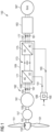
- Fig. 1 schematically illustrates a wind turbine 150 according to an embodiment of the present invention comprising an arrangement 100 for determining a d-component of a reference current according to an embodiment of the present invention.
- the wind turbine 150 includes rotor blades 151 which are connected via a hub 153 to a primary rotor shaft 155 which rotates when wind impacts on the rotor blades 151.
- An optionally gearbox 157 is coupled to the primary shaft 155 and transforms the rotation of the primary shaft 155 to a secondary shaft 159 which rotates within the generator 161.
- the gearbox 157 can be dispensed with so that the wind turbine 150 may be configured as a direct drive wind turbine.
- the generator 161 comprises not illustrated coils wound around stator cores and further comprises a rotor comprising plural magnets, for example permanent magnets that rotate relative to the stator.
- the coils of the generator 161 Upon rotation of the secondary shaft 159 having the permanent magnets attached thereto, the coils of the generator 161 generate currents by induction which are output in three phases 163, 165, 167. In other embodiments, more or less than three phases may be output by the generator 161. Thereby, an energy stream is provided to the AC-DC-AC converter 169.
- the converter 169 comprises a generator side frequency converter 171, a DC-link 173 coupled at an output of the generator side frequency converter 171 and a grid side frequency converter 175 that is coupled to the DC-link 173.
- the generator side frequency converter 171 generates or converts the variable frequency alternating current power stream received from the generator 161 to a substantially direct current power stream at the DC-link 173, while the grid side frequency converter 175 converts the direct current power stream to a fixed frequency power stream which is output in three phases 177, 179, 181.
- the output power stream is transformed by the transformer 183 to a medium voltage or optionally by one or more additional transformers, in particular wind park transformers, in order to be supplied to a utility grid 187.
- the wind turbine converter 169 is controlled by the controller 189 which provides pulse width modulation signals 191 to the generator side frequency converter 171 and which may optionally also provide pulse width modulation signals 193 to the grid side frequency converter 175.
- the converter controller 189 comprises an arrangement 100 for determining a d-component of a reference current in a d-q coordinate system according to an embodiment of the present invention.
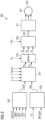
- Fig. 2 schematically illustrates a converter controller 289 according to an embodiment of the present invention as controlling a converter which is connected to the generator 261.
- the generator side frequency converter 271 is controlled by the pulse width modulation signals 291 which are output by the generator side controller 289.
- the generator side controller 289 comprises an arrangement 200 for determining a d-component of a reference current according to an embodiment of the present invention.
- the arrangement 200 receives as an input power P and/or torque T and further receives as an input a modulation index MI and/or a voltage U gen at the output 262 of the generator 161.
- the arrangement 200 determines the d-component of the reference current I dref and provides it to a current controller 201.
- the current controller also receives a q-component of a reference current I qref which is output by an I q reference calculation block 203.
- the I q reference calculation block 203 receives as an input a reference of a power and/or torque P ref /T ref , a generator voltage U gen , a DC-link voltage U dc , an electrical rotational frequency ⁇ e and power and/or torque P/T.
- the current controller 201 further receives the three phase currents I a , I b , I c of the coils of the generator 261, the rotational position ⁇ e of the generator and the rotational frequency (electrical or mechanical) ⁇ e of the generator 261 or the primary shaft 155 or the secondary shaft 159.
- the current controller 201 outputs a d-component of a voltage (V d ) and a q-component of a voltage (V q ) and provides it to a transformation module 204 which transforms the voltages in the d-q coordinate system to voltages of a three phase coordinate system.
- the thereby formed three phase voltages V a , V b , V c are provided to a modulator unit 205 which further receives the DC-link voltage U dc and generates pulse width modulation signals 291 based on the received voltages and provides these pulse width modulation signals 291 to the generator side frequency converter 271.
- the current controller 201 in Fig. 2 may perform a closed-loop regulation of generator currents in the d-q frame with measured 3-phase current as a feedback source.
- the output of the current controller 201 is used by the modulator module 205 for generating PWM (pulse width modulation) signals 291.
- the PWM signals 291 are used to control power electronic switches (such as IGBTs) in the generator side converter 271.
- the arrangement 200 for determining a d-component of a reference current may be configured in different manners.
- the arrangement 200 illustrated in Fig. 2 is illustrated in Fig. 3 as an arrangement 300 for determining a d-component of a reference current.
- the arrangement 300 comprises an arrangement 400 for determining a d-component of a reference current which is also illustrated in Fig. 4 and will be described in detail below.
- the arrangement 300 comprises the arrangement 400 which outputs a first type 307 (I* d, NC ) of the d-component of the reference current.
- the arrangement 300 further comprises a maximum torque per Ampere (MTPA) module 309 which calculates and outputs a second type 311 (I* d, MTPA ) of the d-component of the reference curve.
- the arrangement 300 further comprises a voltage control module 311 which outputs a third type 313 (I* d, VC ) of the d-component of the reference current.
- a processing or selection module 315 determines the minimum or a particular combination or a derived quantity, such as an average, from the first type, the second type and the third type 307, 311, 313 of the d-component of the reference current and outputs the final reference of the d-component of the reference current 317 (I* d ).
- the d-component of the reference current I dref in Fig. 2 or the quantity I* d (317) in Fig. 3 is the generator current reference in the d-q rotating frame which rotates synchronously with the primary or secondary shaft 155, 159 or with the electrical rotation.
- the arrangement 200 for determining the d-component of the reference current may be used for generating the I d reference current.
- the state-of-the-art solution MTPA as implemented in the module 309 illustrated in Fig. 3 may be used.
- the current or generator voltage controller for flux weakening may be implemented.
- the arrangement 400 (also referred to as noise control module) generates the I d current command 307 that can reduce noise and vibration of the wind turbine 150.
- I d commands generated according to another target, such as MTPA or voltage controller (flux weakening controller).
- a deterministic logic 315 is then used (represented as the processing or selection module 315) to decide or to derive the final I d current command 317 according to the generator voltage and the inputs of the three different sources.
- One possible deterministic logic may be to find or select the minimum value of the different types 307, 311, 313 of the d-component as determined by the modules 400, 309 and 312. In other embodiments, another logic may be implemented in the module 315.
- Fig. 3 may be implemented or constructed in a number of ways.
- Fig. 4 schematically illustrates a block diagram of the arrangement 400 for determining a d-component of a reference current as may be used in the arrangement 300 illustrated in Fig. 3 .
- the arrangement 400 thereby comprises a noise/vibration determination module 419 for determining noise/vibration components 421 of oscillations of at least one wind turbine component.
- the oscillations may comprise mechanical and/or electrical oscillations.
- the arrangement 400 further comprises a processing block (402) for calculating a first type (407) of the d-component of the reference current based on the noise/vibration component (421) output by the noise/vibration determination module (419).
- the processing block (402) may be configured in a number of ways.
- the processing block (402) comprises a noise/vibration processing module 423 for obtaining an actual characteristic 425 of the at least one noise/vibration component of the determined noise/vibration components 421.
- the characteristic may for example include an amplitude and/or phase of the at least one noise/vibration component or it may include an analog (or digitally encoded) sinusoidal signal representative of the at least one noise/vibration component.
- a number of different noise/vibration components may also be processed by the noise/vibration processing module 423 to obtain an actual characteristic of plural noise/vibration components.
- the arrangement 400 or the processing block (402) further comprises a reference determination module 427 for providing a reference characteristic 429 of the at least one noise/vibration component or the several noise/vibration components.
- the characteristics 429, 425 output by the reference determination module 427 and the noise/vibration processing module 423 are of the same type.
- the arrangement 400 or the processing block (402) further comprises a subtraction element 431 which determines the difference 433 between the reference characteristic 429 of the noise/vibration component and the actual characteristic 425 of the noise/vibration component and which provides the difference 433 to the control module 437 which outputs a first type 407 of the d-component of the reference current (I* d, NC ), as is also depicted in Fig. 3 and labeled there with reference sign 307.
- the noise/vibration determination module 419 comprises an estimation module 439 for estimating the noise/vibration component of oscillations of the at least one wind turbine component based on current I d , I q , voltage V d , V q output by the generator 161, 261 and based on rotational frequency ⁇ g and angular position ⁇ d of the rotor 155 or 159 of the generator 161, 261.
- the estimation module 439 outputs the estimated noise/vibration components 440.
- a sensorless methodology may be employed in the arrangement and method.
- the noise/vibration determination module 419 comprises a sensor module 441 for sensing noise and/or vibration for measuring the noise/vibration component of oscillations of the at least one wind turbine component and outputting measured noise/vibration components 442.
- the arrangement 400 or the processing block (402) further comprises a switch 443 that is arranged and connected to selectively supply the noise/vibration components of the oscillations of the at least one wind turbine component as measured by the sensor module 441 or as estimated by the estimation module 439 to the noise/vibration processing module 423.
- the reference determination module 427 may for example comprise a look up table comprising information for different working points of the wind turbine or in particular the generator 161, 261.
- the feedback noise/vibration 442, 440 may have a lot of harmonics.
- the noise/vibration processing module 423 may for example comprise a bandpass filter that may attenuate all frequencies not interested in to be attenuated. Only the harmonic component of an interesting frequency (desired to be damped) may pass the bandpass filter. Thereby, the typical interesting frequency may be 6 times the electrical frequency and/or 12 times the electrical frequency of the generator 161, 262. Thereby, electrical frequency is the frequency of the generator phase current.
- the command of noise and vibration at different load points may be saved within the look up table within the reference determination module 427.
- the command and processed feedback signal 425 may be used to calculate a regulation error 433.
- the control module 437 may for example be configured as a PI controller (proportional integral controller) which is used to generate the I d current command 407.
- the feedback source in particular the noise/vibration component 442 output by the sensor module 441 may be measured using a microphone and/or an accelerometer in the sensor-based option.
- the estimation module 439 may for example be configured as a torque ripple and radial force observer in the sensorless option.
- a suitable signal processing algorithm may be required in the noise/vibration processing module 423. Therefore, the resultant error 433 may be input to the proportional-integral (PI) controller which generates a reference for I d in order to reduce noise/vibrations.
- I* d, NC may be supplied to the current controller 201 (see Fig. 2 ) responsible for generating command voltages for a voltage modulator.
- the present invention may be integrated in a conventional vector controlled drive or other alternatives.
- the I d reference may be generated by a maximum torque per Ampere (MTPA) algorithm and/or a voltage controller for flux weakening control under high-speed operation.
- MTPA maximum torque per Ampere
- three distinct reference values for I d may be required to be managed, i.e. the reference values 307, 311 and 313, as is illustrated in Fig. 3 .
- a selection may be performed by choosing the lowest one. Alternatively, a higher priority might be attributed to either noise control or MTPA, according to the application needs.
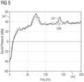
- Fig. 5 illustrates a graph including curves, wherein an abscissa 545 indicates a frequency in Hertz and an ordinate 547 designates a sound pressure in dBa.
- the wind turbine runs at 13 RPM and outputs a power of 2800 kW.
- embodiments of the present invention provide a reduction of 6 dBa in 6f (6 times the generator electrical frequency) tonality by changing I d from 0 A to -800 A. Reduction of the 12f tonality is also visible in Fig. 5 .
- the I d reference may be determined automatically, according to noise/vibration requirements.
- Embodiments of the present invention may provide for a solution for automatic noise/vibration control in a permanent magnet generator drive. Embodiments further may provide for reduced acoustic noise and vibration in a permanent magnet generator drive. Furthermore, two alternative feedback sources for the described control apparatus are possible.
Landscapes
- Engineering & Computer Science (AREA)
- Power Engineering (AREA)
- Life Sciences & Earth Sciences (AREA)
- Sustainable Development (AREA)
- Sustainable Energy (AREA)
- Chemical & Material Sciences (AREA)
- Combustion & Propulsion (AREA)
- Mechanical Engineering (AREA)
- General Engineering & Computer Science (AREA)
- Control Of Eletrric Generators (AREA)
- Wind Motors (AREA)
Claims (14)
- Anordnung (100, 200, 300, 400), die dafür konfiguriert ist, eine d-Komponente (Idref, I*d) eines Referenzstroms in einem d-q-Koordinatensystem zum Reduzieren von Geräusch/Vibration einer Windturbine (150) zu ermitteln, wobei die Anordnung gekennzeichnet ist durch:ein Geräusch/Vibrationsermittlungsmodul (419), das dafür konfiguriert ist, mindestens eine Geräusch/Vibrationskomponente (421) von Schwingungen bei mindestens einer Windturbinenkomponente zu ermitteln, undeinen Verarbeitungsblock (402), der dafür konfiguriert ist, einen ersten Typ (407) der d-Komponente des Referenzstroms basierend auf der vom Geräusch/Vibrationsermittlungsmodul (419) ausgegebenen Geräusch/Vibrationskomponente (421) zu berechnen, wobei der Verarbeitungsblock (402) Folgendes umfasst:ein Geräusch/Vibrationsverarbeitungsmodul (423), das dafür konfiguriert ist, ein tatsächliches Merkmal (425) von mindestens einer Geräusch/Vibrationskomponente der mindestens einen ermittelten Geräusch/Vibrationskomponente zu erlangen,ein Referenzermittlungsmodul (427), das dafür konfiguriert ist, ein Referenzmerkmal (429) der Geräusch/Vibrationskomponente bereitzustellen, undein Steuerungsmodul (437), das dafür konfiguriert ist, den ersten Typ (407) der d-Komponente des Referenzstroms basierend auf einer Differenz (433) zwischen dem tatsächlichen Merkmal (425) und dem Referenzmerkmal (429) der Geräusch/Vibrationskomponente zu berechnen,wobei das Referenzermittlungsmodul (427) dafür ausgelegt ist, das Referenzmerkmal (429) der Geräusch/Vibrationskomponente basierend auf einer Simulation oder einem Offline-Test anhand einer Drehfrequenz (mg) und eines Drehmoments (Te) des Generators (161) als Eingabe zu berechnen.
- Anordnung nach Anspruch 1, wobei das Geräusch/Vibrationsermittlungsmodul Folgendes umfasst:
ein Sensormodul (441) zum Erfassen von Geräusch und/oder Vibration, im Speziellen ein Mikrofon und/oder einen Beschleunigungssensor zum Messen der Geräusch/Vibrationskomponenten (442) von Schwingungen der mindestens einen Windturbinenkomponente. - Anordnung nach einem der Ansprüche 1 bis 2, wobei das Geräusch/Vibrationsermittlungsmodul Folgendes umfasst:
ein Schätzungsmodul (439) zum Schätzen der Geräusch/Vibrationskomponenten (440) von Schwingungen der mindestens einen Windturbinenkomponente basierend auf einem Strom (Id, Iq) und einer Spannung (Vd, Vq), ausgegeben von einem Generator (161, 261) der Windturbine (150), und basierend auf einer Drehfrequenz (mg) und einer Winkelposition (8g) eines Rotors (159) des Generators (161). - Anordnung nach einem der Ansprüche 2 oder 3, wobei das Geräusch/Vibrationsermittlungsmodul Folgendes umfasst:
einen Schalter (443), um wahlweise, alternativ die Geräusch/Vibrationskomponenten der Schwingungen der mindestens einen Windturbinenkomponente wie vom Sensor gemessen oder vom Schätzungsmodul geschätzt für das Geräusch/Vibrationsverarbeitungsmodul (423) bereitzustellen. - Anordnung nach einem der vorhergehenden Ansprüche, wobei das Referenzermittlungsmodul (427) eine Nachschlagetabelle mit Informationen für unterschiedliche Arbeitspunkte umfasst.
- Anordnung nach einem der vorhergehenden Ansprüche,
wobeidas Geräusch/Vibrationsverarbeitungsmodul (423) eine Amplitude und/oder Phase der Geräusch/Vibrationskomponente, die im Speziellen dem 6-Fachen oder 12-Fachen einer elektrischen Frequenz zugehörig ist, als das tatsächliche Merkmal ausgibt, unddas Referenzermittlungsmodul (427) eine Referenzamplitude und/oder Phase der Geräusch/Vibrationskomponente, die im Speziellen dem 6-Fachen oder 12-Fachen einer elektrischen Frequenz zugehörig ist, als das Referenzmerkmal ausgibt. - Anordnung nach einem der vorhergehenden Ansprüche,
wobeidas Geräusch/Vibrationsverarbeitungsmodul (423) ein Wellenformsignal der Geräusch/Vibrationskomponente, das im Speziellen dem 6-Fachen oder 12-Fachen einer elektrischen Frequenz zugehörig ist, als das tatsächliche Merkmal ausgibt, unddas Referenzermittlungsmodul (427) ein Referenzwellensignal der Geräusch/Vibrationskomponente, das im Speziellen dem 6-Fachen oder 12-Fachen einer elektrischen Frequenz zugehörig ist, als das Referenzmerkmal ausgibt. - Anordnung nach einem der vorhergehenden Ansprüche, wobei die Anordnung (400) weiterhin Folgendes umfasst:
ein Subtraktionselement (431), um die Differenz (433) zwischen dem tatsächlichen Merkmal (425) und dem Referenzmerkmal (429) der Geräusch/Vibrationskomponente zu berechnen, und dafür ausgelegt, die Differenz (433) dem Steuerungsmodul (437) bereitzustellen. - Anordnung nach einem der vorhergehenden Ansprüche, weiterhin Folgendes umfassend:
ein MTPA-Modul (309), das dafür ausgelegt ist, einen Maximaldrehmoment-pro-Ampere-Algorithmus anzuwenden, um einen zweiten Typ (311) der d-Komponente des Referenzstroms in einem d-q-Koordinatensystem zu berechnen und den Generator-Gesamtstrom zu minimieren. - Anordnung nach einem der vorhergehenden Ansprüche, weiterhin Folgendes umfassend:
ein Spannungsregelungsmodul (312), das dafür ausgelegt ist, für die Flussschwächung bei Hochgeschwindigkeitsbetrieb einen dritten Typ (313) der d-Komponente des Referenzstroms in einem d-q-Koordinatensystem zu berechnen, um eine Konverter-Übersteuerung zu vermeiden. - Anordnung nach einem der vorhergehenden Ansprüche 9 bis 10, weiterhin Folgendes umfassend:
ein Auswahlmodul (315), um den ersten Typ, den zweiten Typ oder den dritten Typ der d-Komponente des Referenzstroms als die d-Komponente des Referenzstroms auszuwählen, wobei im Speziellen das Minimum (317) ausgewählt wird. - Generatorseitenregler (189), um einen Generatorseiten-Frequenzumrichter (171) einer Windturbine (150) zu regeln, wobei der Generatorseitenregler Folgendes umfasst:eine Anordnung (100), um eine d-Komponente eines Referenzstroms gemäß einem der vorhergehenden Ansprüche zu ermitteln,eine Anordnung (203), um eine q-Komponente eines Referenzstroms zu ermitteln,einen Stromregler (201), um eine d-Komponente und eine q-Komponente einer gewünschten Spannung am Generatorausgang zu ermitteln,einen Modulator (205), um basierend auf der d-Komponente und der q-Komponente der gewünschten Spannung Pulsweitenmodulationssignale für den Generatorseiten-Frequenzumrichter zu erzeugen.
- Windturbine (150), umfassend:einen Generator (161);einen Generatorseiten-Frequenzumrichter (171); undeinen Generatorseitenregler (189) nach Anspruch 12, der gekoppelt ist, um den Generatorseiten-Frequenzumrichter zu regeln.
- Verfahren zum Ermitteln einer d-Komponente eines Referenzstroms in einem d-q-Koordinatensystem, um das Geräusch einer Windturbine zu reduzieren, wobei das Verfahren gekennzeichnet ist durch:
Ermitteln mindestens einer Geräusch/Vibrationskomponente (421) von Schwingungen bei mindestens einer Windturbinenkomponente, und
Berechnen eines ersten Typs (407) der d-Komponente des Referenzstroms basierend auf der vom Geräusch/Vibrationsermittlungsmodul (419) ausgegebenen Geräusch/Vibrationskomponente (421), wobei das Berechnen Folgendes umfasst:Erlangen eines tatsächlichen Merkmals (425) von mindestens einer Geräusch/Vibrationskomponente der ermittelten Geräusch/Vibrationskomponente,Berechnen eines Referenzmerkmals (429) der Geräusch/Vibrationskomponente basierend auf einer Simulation oder einem Offline-Test anhand einer Drehfrequenz (mg) und eines Drehmoments (Te) des Generators (161) als Eingabe undBerechnen des ersten Typs (307, 407) der d-Komponente des Referenzstroms basierend auf einer Differenz (433) zwischen dem tatsächlichen Merkmal (425) und dem Referenzmerkmal (429) der Geräusch/Vibrationskomponente.
Priority Applications (4)
| Application Number | Priority Date | Filing Date | Title |
|---|---|---|---|
| DK15162469.9T DK3076542T4 (da) | 2015-04-02 | 2015-04-02 | Støjstyreenhed til en vindmølle |
| EP15162469.9A EP3076542B2 (de) | 2015-04-02 | 2015-04-02 | Lärmsteuerung für eine windturbine |
| US15/086,354 US10100811B2 (en) | 2015-04-02 | 2016-03-31 | Noise control for a wind turbine |
| CN201610200659.0A CN106050565B (zh) | 2015-04-02 | 2016-04-01 | 用于风力涡轮机的噪声控制的装置和方法 |
Applications Claiming Priority (1)
| Application Number | Priority Date | Filing Date | Title |
|---|---|---|---|
| EP15162469.9A EP3076542B2 (de) | 2015-04-02 | 2015-04-02 | Lärmsteuerung für eine windturbine |
Publications (3)
| Publication Number | Publication Date |
|---|---|
| EP3076542A1 EP3076542A1 (de) | 2016-10-05 |
| EP3076542B1 EP3076542B1 (de) | 2019-05-29 |
| EP3076542B2 true EP3076542B2 (de) | 2024-10-02 |
Family
ID=52813978
Family Applications (1)
| Application Number | Title | Priority Date | Filing Date |
|---|---|---|---|
| EP15162469.9A Active EP3076542B2 (de) | 2015-04-02 | 2015-04-02 | Lärmsteuerung für eine windturbine |
Country Status (4)
| Country | Link |
|---|---|
| US (1) | US10100811B2 (de) |
| EP (1) | EP3076542B2 (de) |
| CN (1) | CN106050565B (de) |
| DK (1) | DK3076542T4 (de) |
Families Citing this family (14)
| Publication number | Priority date | Publication date | Assignee | Title |
|---|---|---|---|---|
| EP3076542B2 (de) * | 2015-04-02 | 2024-10-02 | Siemens Gamesa Renewable Energy A/S | Lärmsteuerung für eine windturbine |
| CN104967378B (zh) * | 2015-05-27 | 2018-10-23 | 北京金风科创风电设备有限公司 | 风力发电机振动和噪声抑制方法及装置 |
| EP3297156B1 (de) * | 2016-09-16 | 2024-06-19 | Siemens Gamesa Renewable Energy A/S | Reduzierung der drehmomentwelligkeit für einen generator |
| CN108252857B (zh) * | 2016-12-29 | 2020-07-28 | 北京金风科创风电设备有限公司 | 风力发电机组的减振方法和装置 |
| CN110506388B (zh) * | 2017-02-21 | 2024-08-06 | 西门子歌美飒可再生能源公司 | 控制风力涡轮发电机 |
| DK3454469T3 (da) * | 2017-09-12 | 2022-03-21 | Siemens Gamesa Renewable Energy As | Drejningsmoment-ripple-reduktion for en generator og vindmølle indbefattende samme |
| JP2019161855A (ja) * | 2018-03-13 | 2019-09-19 | オムロン株式会社 | モータ制御装置および設定装置 |
| EP3599715B1 (de) * | 2018-07-26 | 2022-08-24 | Siemens Gamesa Renewable Energy A/S | Beurteilung der rotortemperatur von windturbinengeneratoren |
| DK3696969T3 (da) * | 2019-02-13 | 2022-05-02 | Siemens Gamesa Renewable Energy As | Harmonisk styring af en omformer |
| EP3723272A1 (de) * | 2019-04-12 | 2020-10-14 | Siemens Gamesa Renewable Energy A/S | Steuerung eines windturbinenwandlers |
| DE102019117477A1 (de) | 2019-06-28 | 2020-12-31 | Wobben Properties Gmbh | Verfahren zum Minimieren von Generatorschwingungen |
| DE102019219857A1 (de) * | 2019-12-17 | 2021-06-17 | Siemens Aktiengesellschaft | Verfahren zur Vermessung des Schwingungsverhaltens eines Antriebsstrangs eines einen Generator aufweisenden Turbosatzes eines mit einem Energienetz verbundenen Kraftwerks |
| US20230088734A1 (en) | 2020-02-13 | 2023-03-23 | Wobben Properties Gmbh | Method for controlling an electric generator of a wind turbine |
| EP4325717A1 (de) * | 2022-08-16 | 2024-02-21 | Wobben Properties GmbH | Verfahren zum steuern eines umrichters |
Citations (7)
| Publication number | Priority date | Publication date | Assignee | Title |
|---|---|---|---|---|
| WO2003030329A1 (de) † | 2001-09-28 | 2003-04-10 | Aloys Wobben | Verfahren zum betrieb eines windparks |
| EP2485388A1 (de) † | 2011-02-04 | 2012-08-08 | Siemens Aktiengesellschaft | Rausch- und Schwingungsverringerung in einem elektromechanischen Wandler durch die Verwendung eines modifizierten Statorspulen-Antriebssignals mit harmonischen Komponenten |
| EP2552012A1 (de) † | 2011-07-27 | 2013-01-30 | Siemens Aktiengesellschaft | Rausch- und Schwingungsverringerung in einem elektromechanischen Wandler durch die Verwendung eines modifizierten Statorspulen-Antriebssignals mit harmonischen Komponenten |
| EP2552013A1 (de) † | 2011-07-27 | 2013-01-30 | Siemens Aktiengesellschaft | Geräusch- und Schwingungsverringerung in einem elektromechanischen Wandler durch die Verwendung eines modifizierten Statorspulen-Antriebssignals mit harmonischen Komponenten |
| EP2670027A1 (de) † | 2012-06-01 | 2013-12-04 | Siemens Aktiengesellschaft | Verfahren und System zur Steuerung eines Generators |
| US20140021894A1 (en) † | 2012-07-19 | 2014-01-23 | GM Global Technology Operations LLC | Torque ripple reduction of multiple harmonic components |
| DE102015205348A1 (de) † | 2015-03-24 | 2016-09-29 | Wobben Properties Gmbh | Verfahren zum Steuern eines Synchrongenerators einer getriebelosen Windenergieanlage |
Family Cites Families (12)
| Publication number | Priority date | Publication date | Assignee | Title |
|---|---|---|---|---|
| JP4007268B2 (ja) * | 2003-07-22 | 2007-11-14 | 株式会社日立製作所 | 風力発電装置 |
| US7679215B2 (en) * | 2004-12-17 | 2010-03-16 | General Electric Company | Wind farm power ramp rate control system and method |
| US7504738B2 (en) * | 2005-09-29 | 2009-03-17 | General Electric Company | Wind turbine and method for operating same |
| US7345373B2 (en) * | 2005-11-29 | 2008-03-18 | General Electric Company | System and method for utility and wind turbine control |
| US7446435B2 (en) * | 2005-11-30 | 2008-11-04 | General Electric Company | Power converter system and method |
| US7423412B2 (en) * | 2006-01-31 | 2008-09-09 | General Electric Company | Method, apparatus and computer program product for injecting current |
| JP4687584B2 (ja) * | 2006-06-26 | 2011-05-25 | パナソニック株式会社 | 洗濯機 |
| JP2008011607A (ja) * | 2006-06-28 | 2008-01-17 | Hitachi Ltd | 可変速風力発電システム |
| US7847526B2 (en) | 2007-09-28 | 2010-12-07 | General Electric Company | System and method for controlling torque ripples in synchronous machines |
| JP5213890B2 (ja) * | 2010-02-23 | 2013-06-19 | 三菱電機株式会社 | モータ駆動装置及び圧縮機及び冷凍サイクル装置及び洗濯機及び洗濯乾燥機及び送風機 |
| JP5382069B2 (ja) * | 2011-07-04 | 2014-01-08 | 株式会社安川電機 | インバータ装置および電動機ドライブシステム |
| EP3076542B2 (de) * | 2015-04-02 | 2024-10-02 | Siemens Gamesa Renewable Energy A/S | Lärmsteuerung für eine windturbine |
-
2015
- 2015-04-02 EP EP15162469.9A patent/EP3076542B2/de active Active
- 2015-04-02 DK DK15162469.9T patent/DK3076542T4/da active
-
2016
- 2016-03-31 US US15/086,354 patent/US10100811B2/en active Active
- 2016-04-01 CN CN201610200659.0A patent/CN106050565B/zh active Active
Patent Citations (9)
| Publication number | Priority date | Publication date | Assignee | Title |
|---|---|---|---|---|
| WO2003030329A1 (de) † | 2001-09-28 | 2003-04-10 | Aloys Wobben | Verfahren zum betrieb eines windparks |
| EP2485388A1 (de) † | 2011-02-04 | 2012-08-08 | Siemens Aktiengesellschaft | Rausch- und Schwingungsverringerung in einem elektromechanischen Wandler durch die Verwendung eines modifizierten Statorspulen-Antriebssignals mit harmonischen Komponenten |
| EP2552012A1 (de) † | 2011-07-27 | 2013-01-30 | Siemens Aktiengesellschaft | Rausch- und Schwingungsverringerung in einem elektromechanischen Wandler durch die Verwendung eines modifizierten Statorspulen-Antriebssignals mit harmonischen Komponenten |
| EP2552013A1 (de) † | 2011-07-27 | 2013-01-30 | Siemens Aktiengesellschaft | Geräusch- und Schwingungsverringerung in einem elektromechanischen Wandler durch die Verwendung eines modifizierten Statorspulen-Antriebssignals mit harmonischen Komponenten |
| EP2670027A1 (de) † | 2012-06-01 | 2013-12-04 | Siemens Aktiengesellschaft | Verfahren und System zur Steuerung eines Generators |
| US20140021894A1 (en) † | 2012-07-19 | 2014-01-23 | GM Global Technology Operations LLC | Torque ripple reduction of multiple harmonic components |
| DE102015205348A1 (de) † | 2015-03-24 | 2016-09-29 | Wobben Properties Gmbh | Verfahren zum Steuern eines Synchrongenerators einer getriebelosen Windenergieanlage |
| WO2016151014A1 (de) † | 2015-03-24 | 2016-09-29 | Wobben Properties Gmbh | Verfahren zum steuern eines synchrongenerators einer getriebelosen windenergieanlage |
| EP3275075A1 (de) † | 2015-03-24 | 2018-01-31 | Wobben Properties GmbH | Verfahren zum steuern eines synchrongenerators einer getriebelosen windenergieanlage |
Non-Patent Citations (5)
| Title |
|---|
| A KUMAR, ET AL: "Comparison of methods of minimization of cogging torque in wind generators using FE analysis", J. INDIAN INST. SCI., vol. 86, 1 August 2006 (2006-08-01), pages 355 - 362 † |
| D. R. MCLNTOSH, IDENTIFICATION AND ANALYSIS OF LOW-FREQUENCY COG- GING TORQUE COMPONENT IN PERMANENT MAGNET MACHINES, XP055662762 † |
| E MULJADI, ET AL: "Cogging Torque Reduction in a Permanent Magnet Wind Turbine Generator", 1 January 2002 (2002-01-01) † |
| HATTORI, ET AL: "Suppression Control Method of Torque Vibration for Brushless DC Motor Utilizing Repetitive Control with Fourier Transform", T. SICE, vol. E2, no. 1, 1 January 2002 (2002-01-01) † |
| Manual, ENERCON E-66 / 18.70, October 1999 † |
Also Published As
| Publication number | Publication date |
|---|---|
| CN106050565A (zh) | 2016-10-26 |
| US10100811B2 (en) | 2018-10-16 |
| CN106050565B (zh) | 2019-09-10 |
| DK3076542T4 (da) | 2024-11-04 |
| EP3076542A1 (de) | 2016-10-05 |
| EP3076542B1 (de) | 2019-05-29 |
| US20160290320A1 (en) | 2016-10-06 |
| DK3076542T3 (da) | 2019-09-02 |
Similar Documents
| Publication | Publication Date | Title |
|---|---|---|
| EP3076542B2 (de) | Lärmsteuerung für eine windturbine | |
| EP2553803B1 (de) | Phasenregelkreisbasiertes torsionsmodusdämpfungssystem und- verfahren | |
| EP3264593B1 (de) | Steuerungsanordnung für einen generator | |
| Stefani et al. | Doubly fed induction machines diagnosis based on signature analysis of rotor modulating signals | |
| EP3454469B1 (de) | Reduzierung der drehmomentwelligkeit für einen generator und windturbine damit | |
| EP3494635B1 (de) | Steuerungsanordnung für einen generator | |
| EP2623997B1 (de) | Bestimmung einer Phase und einer Frequenz einer elektrischen Quantität einer betriebenen elektrischen Vorrichtung | |
| Liu et al. | Principle and stability analysis of an improved self-sensing control strategy for surface-mounted PMSM drives using second-order generalized integrators | |
| JP2007531478A (ja) | 電動機駆動システム用のセンサレス制御方法および装置 | |
| EP3258594B1 (de) | Steuerung einer elektrischen maschine mit mehrfachen windungssätzen | |
| EP3571761B1 (de) | Steuerung eines windturbinengenerators | |
| EP3614556A1 (de) | Reduzierung der drehmomentwelligkeit für einen generator | |
| CA2794819A1 (en) | Rectifier and inverter based torsional mode damping system and method | |
| US20130200839A1 (en) | Rectifier based torsional mode damping system and method | |
| US11863114B2 (en) | Harmonic direct torque control of an electric machine | |
| CA2794823A1 (en) | Sensorless torsional mode damping system and method |
Legal Events
| Date | Code | Title | Description |
|---|---|---|---|
| PUAI | Public reference made under article 153(3) epc to a published international application that has entered the european phase |
Free format text: ORIGINAL CODE: 0009012 |
|
| AK | Designated contracting states |
Kind code of ref document: A1 Designated state(s): AL AT BE BG CH CY CZ DE DK EE ES FI FR GB GR HR HU IE IS IT LI LT LU LV MC MK MT NL NO PL PT RO RS SE SI SK SM TR |
|
| AX | Request for extension of the european patent |
Extension state: BA ME |
|
| STAA | Information on the status of an ep patent application or granted ep patent |
Free format text: STATUS: REQUEST FOR EXAMINATION WAS MADE |
|
| 17P | Request for examination filed |
Effective date: 20161220 |
|
| RBV | Designated contracting states (corrected) |
Designated state(s): AL AT BE BG CH CY CZ DE DK EE ES FI FR GB GR HR HU IE IS IT LI LT LU LV MC MK MT NL NO PL PT RO RS SE SI SK SM TR |
|
| RAP1 | Party data changed (applicant data changed or rights of an application transferred) |
Owner name: SIEMENS AKTIENGESELLSCHAFT |
|
| GRAP | Despatch of communication of intention to grant a patent |
Free format text: ORIGINAL CODE: EPIDOSNIGR1 |
|
| STAA | Information on the status of an ep patent application or granted ep patent |
Free format text: STATUS: GRANT OF PATENT IS INTENDED |
|
| RIC1 | Information provided on ipc code assigned before grant |
Ipc: H02P 29/00 20160101AFI20181102BHEP Ipc: H02P 9/42 20060101ALI20181102BHEP Ipc: H02P 21/00 20160101ALI20181102BHEP Ipc: H02P 6/18 20160101ALI20181102BHEP |
|
| INTG | Intention to grant announced |
Effective date: 20181130 |
|
| GRAS | Grant fee paid |
Free format text: ORIGINAL CODE: EPIDOSNIGR3 |
|
| GRAA | (expected) grant |
Free format text: ORIGINAL CODE: 0009210 |
|
| STAA | Information on the status of an ep patent application or granted ep patent |
Free format text: STATUS: THE PATENT HAS BEEN GRANTED |
|
| RAP1 | Party data changed (applicant data changed or rights of an application transferred) |
Owner name: SIEMENS GAMESA RENEWABLE ENERGY A/S |
|
| AK | Designated contracting states |
Kind code of ref document: B1 Designated state(s): AL AT BE BG CH CY CZ DE DK EE ES FI FR GB GR HR HU IE IS IT LI LT LU LV MC MK MT NL NO PL PT RO RS SE SI SK SM TR |
|
| REG | Reference to a national code |
Ref country code: GB Ref legal event code: FG4D |
|
| REG | Reference to a national code |
Ref country code: CH Ref legal event code: EP |
|
| REG | Reference to a national code |
Ref country code: DE Ref legal event code: R096 Ref document number: 602015031041 Country of ref document: DE |
|
| REG | Reference to a national code |
Ref country code: AT Ref legal event code: REF Ref document number: 1138856 Country of ref document: AT Kind code of ref document: T Effective date: 20190615 |
|
| REG | Reference to a national code |
Ref country code: IE Ref legal event code: FG4D |
|
| REG | Reference to a national code |
Ref country code: DK Ref legal event code: T3 Effective date: 20190829 |
|
| REG | Reference to a national code |
Ref country code: NL Ref legal event code: FP |
|
| REG | Reference to a national code |
Ref country code: LT Ref legal event code: MG4D |
|
| PG25 | Lapsed in a contracting state [announced via postgrant information from national office to epo] |
Ref country code: AL Free format text: LAPSE BECAUSE OF FAILURE TO SUBMIT A TRANSLATION OF THE DESCRIPTION OR TO PAY THE FEE WITHIN THE PRESCRIBED TIME-LIMIT Effective date: 20190529 Ref country code: PT Free format text: LAPSE BECAUSE OF FAILURE TO SUBMIT A TRANSLATION OF THE DESCRIPTION OR TO PAY THE FEE WITHIN THE PRESCRIBED TIME-LIMIT Effective date: 20190930 Ref country code: ES Free format text: LAPSE BECAUSE OF FAILURE TO SUBMIT A TRANSLATION OF THE DESCRIPTION OR TO PAY THE FEE WITHIN THE PRESCRIBED TIME-LIMIT Effective date: 20190529 Ref country code: SE Free format text: LAPSE BECAUSE OF FAILURE TO SUBMIT A TRANSLATION OF THE DESCRIPTION OR TO PAY THE FEE WITHIN THE PRESCRIBED TIME-LIMIT Effective date: 20190529 Ref country code: HR Free format text: LAPSE BECAUSE OF FAILURE TO SUBMIT A TRANSLATION OF THE DESCRIPTION OR TO PAY THE FEE WITHIN THE PRESCRIBED TIME-LIMIT Effective date: 20190529 Ref country code: NO Free format text: LAPSE BECAUSE OF FAILURE TO SUBMIT A TRANSLATION OF THE DESCRIPTION OR TO PAY THE FEE WITHIN THE PRESCRIBED TIME-LIMIT Effective date: 20190829 Ref country code: LT Free format text: LAPSE BECAUSE OF FAILURE TO SUBMIT A TRANSLATION OF THE DESCRIPTION OR TO PAY THE FEE WITHIN THE PRESCRIBED TIME-LIMIT Effective date: 20190529 Ref country code: FI Free format text: LAPSE BECAUSE OF FAILURE TO SUBMIT A TRANSLATION OF THE DESCRIPTION OR TO PAY THE FEE WITHIN THE PRESCRIBED TIME-LIMIT Effective date: 20190529 |
|
| PG25 | Lapsed in a contracting state [announced via postgrant information from national office to epo] |
Ref country code: LV Free format text: LAPSE BECAUSE OF FAILURE TO SUBMIT A TRANSLATION OF THE DESCRIPTION OR TO PAY THE FEE WITHIN THE PRESCRIBED TIME-LIMIT Effective date: 20190529 Ref country code: GR Free format text: LAPSE BECAUSE OF FAILURE TO SUBMIT A TRANSLATION OF THE DESCRIPTION OR TO PAY THE FEE WITHIN THE PRESCRIBED TIME-LIMIT Effective date: 20190830 Ref country code: BG Free format text: LAPSE BECAUSE OF FAILURE TO SUBMIT A TRANSLATION OF THE DESCRIPTION OR TO PAY THE FEE WITHIN THE PRESCRIBED TIME-LIMIT Effective date: 20190829 Ref country code: RS Free format text: LAPSE BECAUSE OF FAILURE TO SUBMIT A TRANSLATION OF THE DESCRIPTION OR TO PAY THE FEE WITHIN THE PRESCRIBED TIME-LIMIT Effective date: 20190529 |
|
| REG | Reference to a national code |
Ref country code: AT Ref legal event code: MK05 Ref document number: 1138856 Country of ref document: AT Kind code of ref document: T Effective date: 20190529 |
|
| PG25 | Lapsed in a contracting state [announced via postgrant information from national office to epo] |
Ref country code: AT Free format text: LAPSE BECAUSE OF FAILURE TO SUBMIT A TRANSLATION OF THE DESCRIPTION OR TO PAY THE FEE WITHIN THE PRESCRIBED TIME-LIMIT Effective date: 20190529 Ref country code: SK Free format text: LAPSE BECAUSE OF FAILURE TO SUBMIT A TRANSLATION OF THE DESCRIPTION OR TO PAY THE FEE WITHIN THE PRESCRIBED TIME-LIMIT Effective date: 20190529 Ref country code: EE Free format text: LAPSE BECAUSE OF FAILURE TO SUBMIT A TRANSLATION OF THE DESCRIPTION OR TO PAY THE FEE WITHIN THE PRESCRIBED TIME-LIMIT Effective date: 20190529 Ref country code: RO Free format text: LAPSE BECAUSE OF FAILURE TO SUBMIT A TRANSLATION OF THE DESCRIPTION OR TO PAY THE FEE WITHIN THE PRESCRIBED TIME-LIMIT Effective date: 20190529 Ref country code: CZ Free format text: LAPSE BECAUSE OF FAILURE TO SUBMIT A TRANSLATION OF THE DESCRIPTION OR TO PAY THE FEE WITHIN THE PRESCRIBED TIME-LIMIT Effective date: 20190529 |
|
| REG | Reference to a national code |
Ref country code: DE Ref legal event code: R026 Ref document number: 602015031041 Country of ref document: DE |
|
| PG25 | Lapsed in a contracting state [announced via postgrant information from national office to epo] |
Ref country code: SM Free format text: LAPSE BECAUSE OF FAILURE TO SUBMIT A TRANSLATION OF THE DESCRIPTION OR TO PAY THE FEE WITHIN THE PRESCRIBED TIME-LIMIT Effective date: 20190529 Ref country code: IT Free format text: LAPSE BECAUSE OF FAILURE TO SUBMIT A TRANSLATION OF THE DESCRIPTION OR TO PAY THE FEE WITHIN THE PRESCRIBED TIME-LIMIT Effective date: 20190529 |
|
| PLBI | Opposition filed |
Free format text: ORIGINAL CODE: 0009260 |
|
| PLAX | Notice of opposition and request to file observation + time limit sent |
Free format text: ORIGINAL CODE: EPIDOSNOBS2 |
|
| PG25 | Lapsed in a contracting state [announced via postgrant information from national office to epo] |
Ref country code: TR Free format text: LAPSE BECAUSE OF FAILURE TO SUBMIT A TRANSLATION OF THE DESCRIPTION OR TO PAY THE FEE WITHIN THE PRESCRIBED TIME-LIMIT Effective date: 20190529 |
|
| 26 | Opposition filed |
Opponent name: ENERCON GMBH Effective date: 20200227 |
|
| PG25 | Lapsed in a contracting state [announced via postgrant information from national office to epo] |
Ref country code: PL Free format text: LAPSE BECAUSE OF FAILURE TO SUBMIT A TRANSLATION OF THE DESCRIPTION OR TO PAY THE FEE WITHIN THE PRESCRIBED TIME-LIMIT Effective date: 20190529 |
|
| PG25 | Lapsed in a contracting state [announced via postgrant information from national office to epo] |
Ref country code: SI Free format text: LAPSE BECAUSE OF FAILURE TO SUBMIT A TRANSLATION OF THE DESCRIPTION OR TO PAY THE FEE WITHIN THE PRESCRIBED TIME-LIMIT Effective date: 20190529 |
|
| PLBB | Reply of patent proprietor to notice(s) of opposition received |
Free format text: ORIGINAL CODE: EPIDOSNOBS3 |
|
| PG25 | Lapsed in a contracting state [announced via postgrant information from national office to epo] |
Ref country code: MC Free format text: LAPSE BECAUSE OF FAILURE TO SUBMIT A TRANSLATION OF THE DESCRIPTION OR TO PAY THE FEE WITHIN THE PRESCRIBED TIME-LIMIT Effective date: 20190529 |
|
| REG | Reference to a national code |
Ref country code: CH Ref legal event code: PL |
|
| PG25 | Lapsed in a contracting state [announced via postgrant information from national office to epo] |
Ref country code: LI Free format text: LAPSE BECAUSE OF NON-PAYMENT OF DUE FEES Effective date: 20200430 Ref country code: LU Free format text: LAPSE BECAUSE OF NON-PAYMENT OF DUE FEES Effective date: 20200402 Ref country code: CH Free format text: LAPSE BECAUSE OF NON-PAYMENT OF DUE FEES Effective date: 20200430 |
|
| REG | Reference to a national code |
Ref country code: BE Ref legal event code: MM Effective date: 20200430 |
|
| PG25 | Lapsed in a contracting state [announced via postgrant information from national office to epo] |
Ref country code: BE Free format text: LAPSE BECAUSE OF NON-PAYMENT OF DUE FEES Effective date: 20200430 |
|
| PG25 | Lapsed in a contracting state [announced via postgrant information from national office to epo] |
Ref country code: IE Free format text: LAPSE BECAUSE OF NON-PAYMENT OF DUE FEES Effective date: 20200402 |
|
| APAH | Appeal reference modified |
Free format text: ORIGINAL CODE: EPIDOSCREFNO |
|
| APBM | Appeal reference recorded |
Free format text: ORIGINAL CODE: EPIDOSNREFNO |
|
| APBP | Date of receipt of notice of appeal recorded |
Free format text: ORIGINAL CODE: EPIDOSNNOA2O |
|
| APBQ | Date of receipt of statement of grounds of appeal recorded |
Free format text: ORIGINAL CODE: EPIDOSNNOA3O |
|
| PG25 | Lapsed in a contracting state [announced via postgrant information from national office to epo] |
Ref country code: MT Free format text: LAPSE BECAUSE OF FAILURE TO SUBMIT A TRANSLATION OF THE DESCRIPTION OR TO PAY THE FEE WITHIN THE PRESCRIBED TIME-LIMIT Effective date: 20190529 Ref country code: CY Free format text: LAPSE BECAUSE OF FAILURE TO SUBMIT A TRANSLATION OF THE DESCRIPTION OR TO PAY THE FEE WITHIN THE PRESCRIBED TIME-LIMIT Effective date: 20190529 |
|
| PG25 | Lapsed in a contracting state [announced via postgrant information from national office to epo] |
Ref country code: MK Free format text: LAPSE BECAUSE OF FAILURE TO SUBMIT A TRANSLATION OF THE DESCRIPTION OR TO PAY THE FEE WITHIN THE PRESCRIBED TIME-LIMIT Effective date: 20190529 Ref country code: IS Free format text: LAPSE BECAUSE OF FAILURE TO SUBMIT A TRANSLATION OF THE DESCRIPTION OR TO PAY THE FEE WITHIN THE PRESCRIBED TIME-LIMIT Effective date: 20190929 |
|
| REG | Reference to a national code |
Ref country code: DE Ref legal event code: R082 Ref document number: 602015031041 Country of ref document: DE Representative=s name: SAUTHOFF, KARSTEN, DIPL.-ING. UNIV., DE |
|
| P01 | Opt-out of the competence of the unified patent court (upc) registered |
Effective date: 20230530 |
|
| APBU | Appeal procedure closed |
Free format text: ORIGINAL CODE: EPIDOSNNOA9O |
|
| PUAH | Patent maintained in amended form |
Free format text: ORIGINAL CODE: 0009272 |
|
| STAA | Information on the status of an ep patent application or granted ep patent |
Free format text: STATUS: PATENT MAINTAINED AS AMENDED |
|
| 27A | Patent maintained in amended form |
Effective date: 20241002 |
|
| AK | Designated contracting states |
Kind code of ref document: B2 Designated state(s): AL AT BE BG CH CY CZ DE DK EE ES FI FR GB GR HR HU IE IS IT LI LT LU LV MC MK MT NL NO PL PT RO RS SE SI SK SM TR |
|
| REG | Reference to a national code |
Ref country code: DE Ref legal event code: R102 Ref document number: 602015031041 Country of ref document: DE |
|
| REG | Reference to a national code |
Ref country code: NL Ref legal event code: FP |
|
| REG | Reference to a national code |
Ref country code: DK Ref legal event code: T4 Effective date: 20241028 |
|
| PGFP | Annual fee paid to national office [announced via postgrant information from national office to epo] |
Ref country code: NL Payment date: 20250424 Year of fee payment: 11 |
|
| PGFP | Annual fee paid to national office [announced via postgrant information from national office to epo] |
Ref country code: DE Payment date: 20250428 Year of fee payment: 11 |
|
| PGFP | Annual fee paid to national office [announced via postgrant information from national office to epo] |
Ref country code: DK Payment date: 20250424 Year of fee payment: 11 |
|
| PGFP | Annual fee paid to national office [announced via postgrant information from national office to epo] |
Ref country code: FR Payment date: 20250424 Year of fee payment: 11 |
|
| PGFP | Annual fee paid to national office [announced via postgrant information from national office to epo] |
Ref country code: GB Payment date: 20260323 Year of fee payment: 12 |