EP3075894A1 - Sewing machine - Google Patents
Sewing machine Download PDFInfo
- Publication number
- EP3075894A1 EP3075894A1 EP15185872.7A EP15185872A EP3075894A1 EP 3075894 A1 EP3075894 A1 EP 3075894A1 EP 15185872 A EP15185872 A EP 15185872A EP 3075894 A1 EP3075894 A1 EP 3075894A1
- Authority
- EP
- European Patent Office
- Prior art keywords
- needle
- bar
- output
- swing
- axis
- Prior art date
- Legal status (The legal status is an assumption and is not a legal conclusion. Google has not performed a legal analysis and makes no representation as to the accuracy of the status listed.)
- Granted
Links
- 238000009958 sewing Methods 0.000 title claims abstract description 99
- 239000004744 fabric Substances 0.000 claims abstract description 58
- 230000008859 change Effects 0.000 claims description 31
- 238000006073 displacement reaction Methods 0.000 description 74
- 238000010586 diagram Methods 0.000 description 24
- 230000007246 mechanism Effects 0.000 description 15
- 230000000694 effects Effects 0.000 description 10
- 230000015572 biosynthetic process Effects 0.000 description 7
- 238000012937 correction Methods 0.000 description 7
- 230000003993 interaction Effects 0.000 description 4
- 230000009471 action Effects 0.000 description 3
- 238000005516 engineering process Methods 0.000 description 3
- 230000004048 modification Effects 0.000 description 3
- 238000012986 modification Methods 0.000 description 3
- 238000011144 upstream manufacturing Methods 0.000 description 3
- 230000008901 benefit Effects 0.000 description 2
- 230000007423 decrease Effects 0.000 description 2
- 238000000034 method Methods 0.000 description 1
- 230000000717 retained effect Effects 0.000 description 1
- 230000000979 retarding effect Effects 0.000 description 1
- 238000003786 synthesis reaction Methods 0.000 description 1
- 230000002194 synthesizing effect Effects 0.000 description 1
Images


Classifications
-
- D—TEXTILES; PAPER
- D05—SEWING; EMBROIDERING; TUFTING
- D05B—SEWING
- D05B19/00—Programme-controlled sewing machines
- D05B19/003—Zig-zag sewing machines with electric or electronic programming
-
- D—TEXTILES; PAPER
- D05—SEWING; EMBROIDERING; TUFTING
- D05B—SEWING
- D05B19/00—Programme-controlled sewing machines
-
- D—TEXTILES; PAPER
- D05—SEWING; EMBROIDERING; TUFTING
- D05B—SEWING
- D05B3/00—Sewing apparatus or machines with mechanism for lateral movement of the needle or the work or both for making ornamental pattern seams, for sewing buttonholes, for reinforcing openings, or for fastening articles, e.g. buttons, by sewing
- D05B3/02—Sewing apparatus or machines with mechanism for lateral movement of the needle or the work or both for making ornamental pattern seams, for sewing buttonholes, for reinforcing openings, or for fastening articles, e.g. buttons, by sewing with mechanisms for needle-bar movement
-
- D—TEXTILES; PAPER
- D05—SEWING; EMBROIDERING; TUFTING
- D05B—SEWING
- D05B55/00—Needle holders; Needle bars
- D05B55/14—Needle-bar drives
-
- D—TEXTILES; PAPER
- D05—SEWING; EMBROIDERING; TUFTING
- D05B—SEWING
- D05B69/00—Driving-gear; Control devices
Definitions
- the present invention relates to a sewing machine that can form zig-zag stitches by swinging a needle bar from side to side relative to a cloth feeding direction.
- Sewing machines which form stitches of a zig-zag pattern and a lettering pattern by swinging a needle bar from side to side relative to a cloth feeding direction. According to such sewing machines, the needle bar swings from side to side in accordance with an up-and-down motion of the needle bar. Hence, the needle bar is located at the right and left needle drop positions.
- Sewing machines are provided with a needle drop hole in a stage on which a cloth is placed.
- the needle drop hole extends in an orthogonal direction to the cloth feeding direction.
- the needle bar can swing in the direction in which the needle drop hole extends. By swinging the needle bar, a needle can fall to an arbitrary location within the needle drop hole.
- a position of the needle relative to the needle drop hole is called a base line.
- the position of the needle when the needle falls to the center in the needle drop hole is called a center base line.
- the position of the needle when the needle falls to the left side in the needle drop hole is called a left base line.
- the position of the needle when the needle falls to the right side in the needle drop hole is called a right base line.
- the right and left sides are defined with reference to the cloth feeding direction.
- Sewing machines include a swing mechanism that swings the needle bar from side to side relative to the cloth feeding direction. This swing mechanism changes the base line of the needle.
- the swing mechanism can change the position of the needle from the left base line to the right base line, and from the right base line to the left base line. By changing the base line in this way, stitches for a zig-zag shape can be formed.
- the swing mechanism can adjust the width of the swing of the needle bar from side to side.
- the width of zig-zag sewing can be adjusted.
- sewing machines can realize complex sewing, such as whip stitch, pattern stitch, and letter stitch.
- the needle and the shuttle are adjustable so as to form a stitch with a certain margin range.
- this non-synchronization in the interaction occurs beyond the margin range, it becomes difficult to form a stitch.
- the amount of swing of the needle bar is limited within a range that still enables the non-synchronization of the interaction between the needle and the shuttle to form a stitch.
- JP H01-42229 A discloses a scheme of causing a phase shifting when a rotational motion is converted into a linear motion by utilizing a positional change of the needle bar caused by the swing of the needle bar, and controlling the timing of the up-and-down motion of the needle bar, thereby reducing the non-synchronization of the interaction between the needle and the shuttle while increasing the amount of swing of the needle bar.
- JP H01-42229 A According to the scheme disclosed in JP H01-42229 A , however, the positional relationship among respective components that construct a sewing machine is significantly limited. Hence, the scheme of JP H01-42229 A is applicable to industrial sewing machines, but in view of the work positional relationship of normal domestic sewing machines, sewing machines become zig-zag sewing machines that move the needle bar back and forth relative to a user. Hence, it is not practical to apply the above scheme to normal domestic sewing machines.
- the present invention has been proposed to address the above technical problems of conventional technologies, and it is an objective of the present invention to provide a sewing machine that can correct an out-of-timing between a needle and a shuttle caused when a needle bar swings from side to side relative to a cloth feeding direction to be within a range that still enables a formation of stitches with a simple structure.
- a sewing machine moves, relative to a cloth, a needle attached to a needle bar up and down based on drive force from a rotating upper shaft to form a stitch, and the sewing machine includes:
- the first output generating unit may include: a crank provided at the upper shaft; and a crank rod connected with the crank, and a leading end of the crank rod may serve as the first output point.
- the needle-bar swing unit may include: a second output generating unit moving a second output point in an orthogonal direction to the cloth feeding direction; and a swing rod transferring a change in a position of the second output point to the needle bar.
- the output axis moving unit may include a guide which is connected with the swing rod, and which rotates around and moves relative to a guide shaft extending in a vertical direction, and the leading end of the crank rod may move in accordance with a movement of the guide.
- the guide may include two arms each forming a constant angle; one of the arms may be connected so as to be freely rotatable relative to the swing rod; a vertical axis in parallel with the guide shaft may be disposed at a leading end of the other arm; and the leading end of the crank rod may be connected so as to be freely rotatable relative to the vertical axis.
- the sewing machine may further include a shuttle supplying a lower thread while rotating in a horizontal or vertical direction, in which, when the needle bar rotates in an opposite direction to a rotation direction of the shuttle, the vertical shaft may swing so as to come close to the shuttle.
- the present invention by changing the motion trajectory of the needle so as to correspond to the swing of the needle bar, a change in sewing condition (needle displacement) caused due to a change in the position relationship between the needle and the shuttle can be corrected. Hence, even if the width of the swing is increased, an appropriate stitch can be formed. In addition, the above effects can be accomplished without a large modification to the structure of conventional sewing machines.
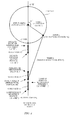
- FIG. 1 is a line drawing illustrating an internal structure of a sewing machine of this embodiment.
- a cloth feeding direction, an orthogonal direction to the cloth feeding direction, and a vertical direction are defined as a Y direction, an X direction, and a Z direction, respectively.
- a sewing machine includes a needle bar 1 and a shuttle 2.
- the needle bar 1 supports a needle 1b with a needle hole 1a in which an upper thread is inserted.
- An unillustrated thread take-up lever supplies the upper thread to the needle 1b from a thread supply source.
- the thread take-up lever changes an amount of supplied upper thread to the needle bar 1b.
- the shuttle 2 includes an unillustrated inner shuttle that retains thereinside a bobbin around which a lower thread is wound, and, an outer shuttle 2a that catches the upper thread.
- the outer shuttle 2a catches the upper thread through a tip 2b.
- Drive force from an unillustrated first motor 5 rotates an upper shaft 3, and the rotational motion is transferred to the needle bar 1 and the unillustrated thread take-up lever.
- the rotational motion of the upper thread 3 is also transferred to a lower shaft 4 through a toothed pulley 3a, a toothed pulley 4a, and a toothed belt 6, and is transferred to the shuttle 2 and an unillustrated cloth feeding mechanism.
- FIG. 2 is a diagram illustrating a structure of a controller C of the sewing machine of this embodiment.
- the sewing machine of this embodiment includes the controller C to form stitches in accordance with the size of zig-zag sewing specified by a user.
- the controller C includes a swing width determining unit C1 and a motor control unit C2. This controller C is connected with a swing instruction input unit I1 and a sewing instruction input unit I2.
- the swing instruction input unit I1 receives an amplitude of swing desired by the user.
- the swing instruction input unit I1 outputs signals in accordance with the received amplitude of swing.
- the swing instruction input unit I1 is an input interface that includes, for example, a touch panel, a mechanical dial, and an adjust knob.
- the sewing instruction unit I2 receives a sewing instruction from the user.
- the sewing instruction input unit I2 outputs signals in accordance with the received sewing instruction.
- the sewing instruction input unit I2 is an input interface that includes, for example, a foot controller and a switch of the sewing machine.
- the swing width determining unit C1 determines the amount of swing of the needle bar 1 in accordance with the user's desire.
- the swing width determining unit C1 receives signals from the swing instruction input unit I1. Next, the amount of swing in accordance with the signals is determined. The determined amount of swing is transmitted to the motor control unit C2.
- the motor control unit C2 outputs drive instructions to the first motor 5 and a second motor 5a.
- the drive instruction to be output is determined in accordance with the signals from the sewing instruction input unit I2 and the amount of swing from the swing width determining unit C1.
- FIG. 3 is a diagram illustrating a moving position of a connection portion of a motor-shaft crank of the second motor 5a.
- the second motor 5a transfers drive force to an output point P2, and moves the position.
- the second motor 5a changes the position to which the output point P2 is moved in accordance with the amount of swing from the swing width determining unit C1.
- a needle-bar up-and-down swing unit A includes the first motor 5, the upper shaft 3, a needle-bar crank 7, a needle-bar crank rod 8, an assist rod 13, a needle-bar holder 9, and the needle bar 1.
- the upper shaft 3 and the needle bar 1 are linked with each other through the needle-bar crank 7, the needle-bar crank rod 8, the assist rod 13, and the needle-bar holder 9. Drive force from the upper shaft 3 is transferred to the needle bar 1.
- the upper shaft 3 is freely rotatably supported by an unillustrated bearing fastened to the interior of the sewing machine.
- the upper shaft 3 has a rotational axis in the orthogonal direction (X direction in FIG. 1 ) to the cloth feeding direction.
- Drive force from the first motor 5 is transferred to the upper shaft 3, and the upper shaft 3 rotates around the rotational axis.
- the needle-bar crank 7 is provided at the leading end of the upper shaft 3.
- the needle-bar crank 7 is one end of the upper shaft 3 bent at a substantially right angle.
- the needle-bar crank 7 synchronously rotates with the upper shaft 3.
- a connection portion 7a with the needle-bar crank rod 8 is provided at the leading end of the needle-bar crank 7.
- the connection portion 7a is the leading end of the needle-bar crank 7 bent at a substantially right angle.
- the connection portion 7a is an axis that extends in the orthogonal direction (X direction in FIG. 1 ) to the cloth feeding direction.
- the needle-bar crank 7 and the upper end of the needle-bar crank rod 8 are connected with each other through the connection portion 7a.
- the needle-bar crank rod 8 is connected so as to be freely rotatable around the connection portion 7a.
- the needle-bar crank rod 8 is connected so as to be slidable in the orthogonal direction (X direction in FIG. 1 ) to the cloth feeding direction along the connection portion 7a.
- the needle-bar crank rod 8 is formed in a substantially T-shape upside down.
- the needle-bar crank rod 8 includes a vertical portion 8a and a horizontal portion 8b.
- the vertical portion 8a is an axis that extends in the vertical direction (Z direction in FIG. 1 ).
- the needle-bar crank rod 8 is connected to the upper end of the vertical portion 8a.
- the horizontal portion 8b is located at the lower end of the vertical portion 8a.
- the horizontal portion 8b is a bar member that extends in parallel with the upper shaft 3, i.e., the orthogonal direction (X direction in FIG. 1 ) to the cloth feeding direction.
- the one end of the horizontal portion 8b is connected with a vertical shaft 12a of a guide 12.
- the horizontal portion 8b is slidable in the vertical direction along the vertical shaft 12a.
- the horizontal portion 8b is connected so as to be freely rotatable around the vertical shaft 12a.
- the vertical shaft 12a rotates around and moves relative to a guide shaft 11.
- the horizontal portion 8b also moves together with the vertical shaft 12a.
- the moving direction of the horizontal portion 8b by the movement of the vertical shaft 12a is consistent with the cloth feeding direction.
- the horizontal portion 8b before movement and the horizontal portion 8b after the movement are in parallel with each other.
- the direction of the horizontal portion 8b is maintained in the orthogonal direction (X direction in FIG. 1 ) to the cloth feeding direction although the position of the horizontal portion 8b is changed by the above structure.
- the other end of the horizontal portion 8b is connected with the assist rod 13.
- the assist rod 13 is a bar member.
- the one end of the assist rod 13 is connected so as to be slidable along the horizontal portion 8b.
- the assist rod 13 is connected so as to be freely rotatable around the horizontal portion 8b. According to this structure, the assist rod 13 changes the inclination in accordance with a change in position of the horizontal portion 8b in the horizontal direction. Conversely, when the horizontal portion 8b translates in the vertical direction, the assist rod 13 is supported so as to have a constant inclination when viewed from the Y direction, i.e., from the cloth feeding direction (Y direction in FIG. 1 ). In FIG.
- the horizontal portion 8b is disposed at a position that makes the assist rod 13 inclined in the vertical direction.
- the horizontal portion 8b reciprocates in the vertical direction along the vertical shaft 12a.
- the assist rod 13 reciprocates in the vertical direction while being inclined in the vertical direction and maintaining the inclination.
- the needle bar 1 to which power in the vertical direction from the assist rod 13 is transferred through the needle-bar holder 9 reciprocates in the vertical direction together with the reciprocal motion of the horizontal portion 8b in the vertical direction.
- the first motor 5, the upper shaft 3, the needle-bar crank 7, the needle-bar crank rod 8, the assist rod 13, and the needle bar 1 construct the needle-bar up-and-down swing unit A.
- Drive force generated by the first motor 5 swings the needle bar 1 in the vertical direction through the upper shaft 3, the needle-bar crank 7, the needle-bar crank rod 8, and the assist rod 13.
- the upper shaft 3, the needle-bar crank 7, and the needle-bar crank rod 8 in the needle-bar up-and-down swing unit A can be considered as a slider crank mechanism.
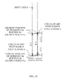
- FIG. 4 is a diagram illustrating a positional relationship among the upper shaft 3, the needle-bar crank 7, and the needle-bar crank rod 8 when the needle bar 1 is located on the center base line.
- the vertical direction in FIG. 4 corresponds to the vertical direction (Z direction) in FIG. 1 .
- the horizontal direction in FIG. 4 corresponds to the cloth feeding direction (Y direction) in FIG. 1 . As illustrated in FIG.
- the upper shaft 3, the needle-bar crank 7, the needle-bar crank rod 8, the connection portion 7a of the needle-bar crank 7, the horizontal portion 8b of the needle-bar crank rod 8, and the vertical shaft 12a can be considered as an input axis I, a node a, a node b, a joint c, an output point P1, and an output axis OA, respectively.
- the output axis OA when viewed in the X direction in FIG. 1 , the output axis OA is located on the same plane as that of the upper shaft 3, i.e., intersects with the upper shaft 3.
- the output axis OA located at this position will be referred to as an output axis OA 1
- the horizontal portion 8b reciprocates on the output axis OA 1 .
- FIG. 5 is a diagram illustrating a positional relationship among the upper shaft 3, the needle-bar crank 7, and the needle-bar crank rod 8 when the needle bar 1 is located on the right base line.
- the eccentric slider crank mechanism illustrated in FIG. 5 when viewed in the X direction in FIG. 1 , the output axis OA is not located on the same plane as that of the upper shaft 3, i.e., does not intersect with the upper shaft 3.
- the output axis located at this position will be referred to as an output axis OA 2 , and the horizontal portion 8b reciprocates on the output axis OA 2 .
- the needle-bar side-to-side swing unit includes the second motor 5a, a swing rod 5b, a needle bar support 5c, and the needle bar 1.
- the second motor 5a and the needle bar 1 are linked with each other through the swing rod 5b, and the needle-bar support 5c. Drive force from the second motor 5a is transferred to the needle bar 1 through those members.
- the second member 5a is driven in accordance with an instruction from the controller C, and rotates a rotation shaft 51a.
- the second motor 5a can change the operation between a clockwise rotation operation that rotates the rotation shaft 51a in the clockwise direction, and a counterclockwise rotation operation that rotates the rotation shaft 51a in the counterclockwise direction.
- the rotation shaft 51a of the second motor 5a is an axis that extends in the cloth feeding direction (Y direction in FIG. 1 ).
- Amotor-shaft crank 51b is provided at the leading end of the rotation shaft 51a.
- the motor-shaft crank 51b is one end of the rotation shaft 51a bent at a substantially right angle.
- the motor-shaft crank 51b synchronously rotates with the rotation shaft 51a.
- a connection portion 51c with the swing rod 5b is provided at the motor-shaft crank 51b.
- the connection portion 51c is the leading end of the motor-shaft crank 51b bent at a substantially right angle.
- the connection portion 51c is an axis that extends in the cloth feeding direction (Y direction in FIG. 1 ).
- the second motor 5a transfers drive force with the connection portion 51c being as the output point P2, and moves the output point P2.
- FIG. 3 is a diagram illustrating a trajectory of the connection portion 51c at the leading end of the motor-shaft crank 51b, i.e., the output point P2.
- the connection portion 51c moves, on a Z-X plane, a circumference around the rotation shaft 51a.
- the connection portion 51c moves between a left base line point P2 left , a center base line point P 2center , and a right base line point P2 right , all located on the circumference.
- the left base line point P2 left is a position of the connection portion 51c where the needle 1b is located on the left base line.
- the center base line point P2 center is a position of the connection portion 51c where the needle 1b is located on the center base line.
- the right base line point P2 right is the position of the connection portion 51c where the needle 1b is located on the right base line.
- the motor-shaft crank 51b and the swing rod 5b are connected through the connection portion 51c that moves as explained above.
- the swing rod 5b is connected so as to be slidable in the cloth feeding direction (Y direction in FIG. 1 ) along the connection portion 51c.
- the swing rod 5b is also connected so as to be freely rotatable around the connection portion 51c.
- an arm 52a that extends in the vertical direction (Z direction in FIG. 1 ) is provided at the center of the swing rod 5b.
- the arm 52a is connected with a guide arm 12b of the guide 12 to be explained later.
- the guide arm 12b rotates around and moves relative to the guide shaft 11.
- the swing rod 5b is connected with the needle-bar support 5c through a needle-bar-support holder 53a.
- the needle-bar support 5c includes the needle-bar-support holder 53a, a needle-bar support shaft 53b, a lower arm 53c, and an upper arm 53d.
- the needle-bar support shaft 53b is a bar member that extends in the vertical direction.
- the needle-bar support shaft 53b has an upper end connected with a shaft 10 that is fixed to the main body of the sewing machine. This shaft 10 is an axis that extends in the cloth feeding direction (Y direction in FIG. 1 ).
- the needle-bar support shaft 53b is freely rotatable around the shaft 10.
- the lower end of the needle-bar support shaft 53b is bent at a substantially right angle, and serves as the lower arm 53c.
- the lower arm 53c extends in the orthogonal direction (X direction in FIG. 1 ) to the cloth feeding direction.
- a connection portion with the needle bar 1 is provided at the lower arm 53c.
- the upper arm 53d is provided at the center of the needle-bar support shaft 53b.
- the upper arm 53d extends in the orthogonal direction (X direction in FIG. 1 ) to the cloth feeding direction.
- a connection portion with the needle bar 1 is provided at the leading end of the upper arm 53d.
- the lower arm 53c and the upper arm 53d slidably support the needle bar 1 in the vertical direction.
- the second motor 5a, the swing rod 5b, the needle-bar support 5c, and the needle bar 1 construct the needle-bar side-to-side swing unit.
- Drive force generated by the second motor 5a swings the needle bar 1 in the orthogonal direction (X direction in FIG. 1 ) to the cloth feeding direction through the swing rod 5b and the needle-bar support 5c.
- the needle-bar phase correcting unit includes the second motor 5a, the swing rod 5b, the guide 12, and the needle-bar crank rod 8.
- the second motor 5a and the needle-bar crank rod 8 are linked with each other through the swing rod 5b and the guide 12.
- the vertical shaft 12a that is the output axis OA of the horizontal portion 8a of the needle-bar crank rod 8 is moved by drive force generated by the second motor 5a.
- the swing rod 5b is connected with the guide 12.
- the guide 12 rotates around the guide shaft 11 fastened to the sewing machine main body.
- the guide 12 includes the vertical shaft 12a, the guide arm 12b, an upper arm 12c, and a lower arm 12d.
- the vertical shaft 12a is an axis that extends in the vertical direction (Z direction in FIG. 1 ) along the guide shaft 11.
- the vertical shaft 12a is connected with the horizontal portion 8b of the needle-bar crank rod 8.
- the vertical shaft 12a restricts the movement of the horizontal portion 8b of the needle-bar crank rod 8 which slides relative to the vertical shaft 12a.
- the vertical shaft 12a is connected through the upper arm 12c and the lower arm 12d.
- the guide shaft 11 is a bar member which is fastened to the sewing machine main body, and which extends in the vertical direction (Z direction in FIG. 1 ).
- the upper arm 12c and the lower arm 12d are connected so as to be freely rotatable around the guide shaft 11.
- the guide arm 12b is a bar member that extends in the horizontal direction.
- the one end of the guide arm 12b is connected with the arm 52a.
- the arm 52a is an axis that extends in the vertical direction of the swing rod 5b.
- the guide arm 12b is connected so as to be freely rotatable around the arm 52a.
- the other end of the guide arm 12b is connected with the upper arm 12c.
- the upper arm 12c and the guide arm 12b are connected with a fixed angle.
- the guide arm 12b has a portion which is connected with the arm 12c and which is also connected with the guide shaft 11.
- the guide arm 12b is connected so as to be freely rotatable around the guide shaft 11.
- Drive force from the second motor 5a is transferred to the guide 12 through the swing rod 5b.
- the guide 12 rotates around the guide shaft 11 by this drive force. That is, when the swing rod 5b moves in the orthogonal direction (X direction in FIG. 1 ) to the cloth feeding direction by the distance L, the guide 12 performs a rotational motion by the distance L.
- the upper arm 12c, the vertical shaft 12a, and the lower arm 12d synchronously move with the motion of the guide arm 12b. That is, since the guide arm 12b and the arm 12c are connected with the fixed angle, the upper shaft 12c synchronously rotates around the guide shaft 11 with the guide arm 12b. In addition, since the upper arm 12c and the vertical shaft 12a are connected with the fixed angle, the vertical shaft 12a synchronously moves around the guide shaft 11 with the upper arm 12c.
- the vertical shaft 12a When viewed in the X direction in FIG. 1 , the vertical shaft 12a translates while extending in the vertical direction. That is, even if it moves, the inclination of the vertical shaft 12a is constant. The movement of the vertical shaft 12a moves the output axis OA of the horizontal portion 8b.
- the second motor 5a, the swing rod 5b, the guide 12, and the needle-bar crank rod 8 construct the needle-bar phase correcting unit.
- Drive force generated by the second motor 5a translates the output axis OA of the horizontal portion 8b through the swing rod 5b and the guide 12.
- FIG. 6 illustrates a structure of the sewing machine when the connection portion 51c is located on the right base line point P2 right .
- the connection portion 51c is moving in the counterclockwise direction (an arrow R1) from the position illustrated in FIG. 1 .
- the swing rod 5b moves in the orthogonal direction (an arrow R2) to the cloth feeding direction.
- the movement of the swing rod 5b also moves the needle-bar support 5c in the orthogonal direction (X direction in the figure) to the cloth feeding direction and to the right side (an arrow R3) relative to the cloth feeding direction.
- the needle bar 1 also moves to the right side (the arrow R3) relative to the cloth feeding direction.
- the guide 12 linked with the swing rod 5b performs a rotational motion around the guide shaft 11 by the movement of the swing rod 5b. That is, the guide arm 12b of the guide 12 rotates around and moves relative to the guide shaft 11 in the clockwise direction (an arrow R4).
- the vertical shaft 12a that synchronously operates with the guide arm 12b rotates around and moves relative to the guide shaft 11 in the clockwise direction (an arrow R5). Accordingly, when viewed in the X direction, the vertical shaft 12a translates to the upstream side in the cloth feeding direction.
- FIG. 7 is a line drawing illustrating a structure of the sewing machine when the connection portion 51c is located on the left base line point P2 left .
- the connection portion 51c is moving in the clockwise direction (an arrow L1) from the position in FIG. 1 .
- the swing rod 5b moves in the orthogonal direction (an arrow L2) to the cloth feeding direction.
- the movement of the swing rod 5b also moves the needle-bar support 5c in the orthogonal direction (X direction in the figure) to the cloth feeding direction and to the left side (an arrow L3) relative to the cloth feeding direction.
- the needle bar 1 also moves to the left side (the arrow L3) relative to the cloth feeding direction.
- the guide 12 linked with the swing rod 5b performs a rotational motion around the guide shaft 11 in the counterclockwise direction by the movement of the swing rod 5b. That is, the guide arm 12b of the guide 12 rotates around and moves relative to the guide shaft 11 in the counterclockwise direction (an arrow L4).
- the vertical shaft 12a that synchronously operates with the guide arm 12b rotates around and moves relative to the guide shaft 11 in the counterclockwise direction (an arrow L5). Accordingly, when viewed in the X direction, the vertical shaft 12a translates to the downstream side in the cloth feeding direction.
- the input axis I in FIG. 4 corresponds to the upper shaft 3
- the node a corresponds to the needle-bar crank 7
- the node b corresponds to the needle-bar crank rod 8.
- the joint c corresponds to the connection portion 7a
- the output point P1 corresponds to the horizontal portion 8b.
- the output point P2 that is the connection portion 51c of the motor-shaft crank is located on the center base line P2 center .
- the input axis I rotates with a fixed position to a point. It is assumed that the rotation angle of the input axis I is ⁇ [°].
- the one end of the node a is provided with the joint c.
- the node a synchronously rotates with the input axis I.
- the joint c moves on the circumference of a circle O which is around the input axis I and which has a radius that is the node a.
- the joint c When the rotation angle of the input axis I is 0 [°], the joint c is located at the highest point. At this time, the output point P1 is located at the highest point of the output axis OA 1 . In addition, when the rotation angle of the input axis I is 180 [°], the joint c is located at the lowest point. At this time, the output point P1 is located at the lowest point of the output axis OA 1 .
- the output axis OA 1 and the needle bar 1 overlap with each other.
- the horizontal portion 8b of the needle-bar crank rod 8 which is the output point P1 and the needle-bar holder 9 are linked through the assist rod 13.
- FIG. 5 is a diagram illustrating a positional relationship among the upper shaft 3 (input axis I), the needle-bar crank 7 (node a), and the needle-bar crank rod 8 (node b) as viewed in the X direction when the connection portion 51c in FIG. 3 is located on the right base line point P2 right .
- the output axis OA is moved in the cloth feeding direction (Y direction) by a distance d from the position of the output axis OA 1 .
- the output point in FIG. 5 will be defined as an output point P1d.
- An axis on which the output point P1d reciprocates will be defined as the output axis OA 2 .
- the input axis I rotates with a fixed position to a point.
- Drive force by the rotation of the input axis I is transferred to the output point P1d through the nodes a and b.
- the horizontal portion 8b of the needle-bar crank rod 8 which is the output point P1d has its movement restricted by the vertical axis 12a in the vertical direction (Z direction).
- the position of the vertical shaft 12a is moved by the distance d in parallel with the Y direction from the position in the case of the center base line.
- the position of the output axis OA 2 translates by the distance d relative to the output axis OA 1 .
- the output point P1d reciprocates on the output axis OA 2 .
- the node a and the node b overlap on a Y-Z plane.
- the rotation angle of the input axis at this time will be defined as ⁇ h [°].
- the output point P1d is not located at the lowest point of the output axis OA 2 .
- the node a and the node b do not overlap on the Y-Z plane but are aligned on a straight line.
- the input-axis rotation angle at this time will be defined as ⁇ 1 [°].
- the assist rod 13 causes the horizontal portion 8b and the needle-bar holder 9 to synchronously operate. In other words, the amount of movement of the horizontal portion 8b in the vertical direction and that of the needle-bar holder 9 are equal.
- the needle bar 1 is also located at the highest point of the motion axis.
- the needle bar 1 is also located at the lowest point of the motion axis.
- the height of the lowest point of the needle 1b substantially remains the same, but a timing of becoming the lowest point is advanced. That is, when the rotation angle ⁇ of the input axis is gradually increased from 0 °, the position of the needle 1b gradually falls together with this increase in rotation angle.
- the needle 1b is located at the lowest point.
- the height of the lowest point of the needle 1b at the input-axis rotation angle of ⁇ 1° becomes substantially consistent with the height of the lowest point of the needle 1b in the case of the center base line by the assist rod 13.
- the motion trajectory of the needle 1b is substantially in conjunction with the trajectory of the output point P1d, and the lowest point of the motion trajectory of the output point P1d is located at a higher position than the lowest point of the motion trajectory of the output point P1.
- the lowest point of the needle 1b on the right base line should be higher than the lowest point of the needle 1b at the center base line, but because the assist rod 13 corrects the position of the needle 1b, the height of the lowest point of the needle 1b on the right base line is substantially consistent with that of the lowest point of the needle 1b on the center base line.
- FIG. 10 is a diagram illustrating a stroke range of the output point on the output axis OA 1 and on the output axis OA 2 .
- a stroke S1 of the up-and-down movement of the output point P1 (horizontal portion 8b) of the output axis OA 1 that intersects the input axis I is indicated by arrows of a thick dotted line
- a stroke S2 of the up-and-down movement of the output point P1 (horizontal portion 8b) of the output axis OA 2 that does not intersect the input axis I is indicated by arrows of a thick solid line.
- FIG. 11 is a diagram illustrating an inclination of the assist rod 13 and a stroke range of the needle-bar holder 9 in the cases of the output axis OA 1 and the output axis OA 2 .
- FIG. 11 for the purpose of explanation, it is assumed that the position of the output point P1 (horizontal portion 8b) maintains the same height even if the output axis OA changes.
- FIG. 11 for the purpose of explanation, it is assumed that the position of the output point P1 (horizontal portion 8b) maintains the same height even if the output axis OA changes.
- a stroke S3 of the up-and-down movement of the needle-bar holder 9 in the case of the output axis OA 1 that intersects the input axis I is indicated by arrows of a thick dotted line
- the stroke S2 of the up-and-down movement of the needle-bar holder 9 in the case of the output axis OA 2 that does not intersect the input axis I is indicated by arrows of a thick solid line.
- the needle bar 1 when viewed in the X direction in FIG. 1 , the needle bar 1 is coaxially disposed with the output axis OA.
- the output axis OA is located coaxially with the needle bar 1b.
- the assist rod 13 is also coaxially located, and transfers the up-and-down movement of the output point P1 to the needle bar 1b.
- the output axis OA is moved to the OA 2
- the relative position between the output axis OA and the needle bar 1b changes.
- the assist rod 13 that changes the inclination the positional change can be compensated.
- the upward shifting of the strokes S2 illustrated in FIG. 10 and the downward shifting of the stroke S4 illustrated in FIG. 11 act simultaneously. That is, the assist rod 13 changes the inclination in accordance with the change of the output axis OA, thereby accomplishing an action of correcting the upward shifting of the stroke S2 caused by the change of the output axis OA. Because of this action, the height of the lowest point of the needle 1b in the case of the left base line and in the case of the center base line becomes substantially consistent.
- the trajectory of the needle bar 1 can be changed. That is, by changing the position on the center base line in FIG. 4 to the position on the right base line in FIG. 5 , a correction that advances the needle bar phase on the right base line in comparison with the needle bar phase on the center base line is performed. Conversely, in the case of the left base line, a correction that retards the needle bar phase in comparison with that of the center base line is performed.
- the sewing machine of this embodiment with the upper thread being inserted in the needle hole 1a of the needle 1b, and the bobbin around which the lower thread is wound being retained in the internal shuttle, when the upper shaft 3 is driven, stitches are formed. More specifically, when the upper shaft 3 is driven by the first motor 5, the rotational motion of the upper shaft 3 is converted into a reciprocal motion by the slider crank mechanism. Hence, the needle bar 1 moves up and down. In addition, the rotation of the upper shaft 3 is transferred to the lower shaft 4 through the upper-shaft pulley 3a, the toothed belt 6, and the lower-shaft pulley 4a. When the lower shaft 4 is rotated together with the rotation of the upper shaft 3, the shuttle 2 is rotated.
- the needle 1b passes through a cloth, and moves to a needle lowest point. Subsequently, the needle 1b is raised on some level, but the upper thread cannot be pulled out from the top face of the cloth due to a friction therewith, and thus a thread loop is formed on the bottom face of the cloth.
- the tip 2a of the external shuttle 2 passes through the thread loop, the bobbin around which the lower thread is wound passes through the thread loop, and the upper thread and the lower thread are intertwined with each other, thereby forming a stitch.
- a phase when the needle 1b and the tip 2b of the shuttle 2 intersect and the tip 2b catches the thread loop is defined as a needle/shuttle intersecting phase.
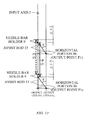
- FIG. 12 illustrates a correlation between the trajectory of the tip of the shuttle 2 and the needle/shuttle intersecting phase in the sewing machine.
- the horizontal axis indicates the phase of the upper shaft 3 and that of the lower shaft 4, while the vertical axis simulates the trajectory of the leading end of the needle 1b and that of the tip 2b of the external shuttle 2.
- the needle/shuttle intersecting phase is around 205 [°]
- the amount of the raise of the needle 1b at the needle/shuttle intersecting phase from the bottom dead center will be defined as a needle displacement ⁇ .
- FIG. 13 is a diagram illustrating a formation of thread loop with each needle displacement ⁇ .
- the size of the thread loop depends on the amount of the needle 1b raised from the lowest point.
- ⁇ 1 indicates an under-displacement of the needle 1b.
- ⁇ 4 indicates an over-displacement of the needle 1b.
- the displacement of the needle 1b is too large like ⁇ 4
- the thread loop becomes too large, and is collapsed due to the self-weight of the thread or twisting, and thus the tip 2a cannot enter the thread loop.
- the needle displacement is too small or too large, it is difficult to form a stitch.
- the needle displacement is required to be set so as to enable the formation of the thread loop, and to allow the tip 2a of the shuttle 2 to enter the thread loop.
- a necessary minimum displacement is indicated as ⁇ 2
- an allowable maximum displacement is indicated as ⁇ 3.
- FIG. 14 illustrates, in conventional sewing machines, a change in the relative motion of the needle 1b and the tip 2a of the shuttle 2 when zig-zag sewing is performed.
- the horizontal axis in FIG. 14 indicates the phase of the upper shaft 3 and that of the lower shaft 4, while the vertical axis indicates the simulated trajectory of the leading end of the needle 1b and that of the tip 2a of the shuttle 2.
- the trajectory of the tip 2a is slightly different from an actual trajectory, but is illustrated with a continuous line for the purpose of explanation. In the example in FIG. 14 , it is assumed that the shuttle 2 rotates in a counterclockwise direction.
- the trajectory of the needle 1b illustrated by solid lines indicates that the needle-bar side-to-side swing unit is not actuated yet and the needle 1b is located on the center base line that is the center.
- the trajectory illustrated by thick lines indicates that the needle 1b swings from side to side by the needle-bar side-to-side swing unit.
- the needle displacement is necessary to be equal to or larger than the necessary minimum displacement ⁇ 2, but equal to or smaller than allowable maximum displacement ⁇ 3.
- the position of the shuttle 2 is constant but the needle 1b swings from side to side from the center base line, and thus the relative position of the needle 1b to the shuttle 2 changes. A change in the positional relationship affects the needle displacement.
- ⁇ R1 When, for example, in conventional sewing machines, representing the needle displacement when the needle 1b is moved to the right side as ⁇ R1, ⁇ R1 is smaller than the needle displacement ⁇ in the center-base-line condition.
- ⁇ L1 representing the needle displacement when the needle 1b is moved to the left side as ⁇ L1, ⁇ L1 becomes larger than the needle displacement ⁇ in the center-base-line condition. That is, even if the needle displacement ⁇ in the center-base-line condition is set to be an appropriate value, when the needle 1b swings from side to side, ⁇ R1 becomes smaller than the minimum necessary displacement ⁇ 2, or ⁇ L1 exceeds the allowable maximum displacement ⁇ 3, and thus it sometime becomes difficult to form an appropriate thread loop.
- a change in the needle displacement due to a position change of the needle 1b increases in proportional to a swing amount Z of the needle 1b which swings from side to side.
- a stitch can be formed only when the needle displacement satisfies a condition ⁇ 2 ⁇ ⁇ R1 ⁇ ⁇ ⁇ ⁇ L1 ⁇ ⁇ 3, the maximum swing amount Z is automatically determined.
- connection portion 51c When zig-zag sewing is performed by the sewing machine of this embodiment, the position of the connection portion 51c is changed by drive force from the second motor 5a, thereby swinging the needle bar 1 from side to side. In addition, when the position of the connection portion 51c changes, the base line of the needle 1b and the position of the output axis OA also change.
- the needle displacement of the sewing machine of this embodiment is a needle displacement obtained by synthesizing the needle displacement in accordance with the base line with the needle displacement in accordance with the position of the output axis OA.
- FIG. 15 illustrates a position of the connection portion 51c, a position of the output axis OA, and a phase of the needle 1b and that of the tip 2b in view of the needle displacement in accordance with a change in the position of the output axis OA.
- the needle displacement in accordance with a change in the base line of the needle 1b is out of consideration.
- the position of the needle bar 1 when viewed in the X direction in FIG. 1 is a reference position 0.
- the upstream side of the cloth feeding direction relative to the reference position will be defined as a positive side, while the downstream side of the cloth feeding direction will be defined as a negative side.
- connection portion 51c moves to P2 left or P2 right in accordance with a drive timing of the second motor 5a.
- the output axis OA also moves in accordance with the connection portion 51.
- the connection portion 51c moves to P2 right
- the output axis OA moves to a position at the upstream side of the cloth feeding direction apart from the reference position by a distance d.
- the connection portion 51c moves to P2 left
- the output axis OA moves to a position at the downstream side of the cloth feeding direction apart from the reference position by a distance d (-d).
- a solid line in the motion trajectory of the needle 1b in FIG. 15 indicates the trajectory of the needle 1b when the output axis OA is located at the reference position 0.
- the connection portion 51c is always located on P2 center . That is, in the solid line in FIG. 15 , the position of the output axis is unchanged.
- the motion trajectory representing the needle up-and-down movement becomes a waveform like a sinusoidal wave.
- a thick line in FIG. 15 indicates the trajectory of the needle 1b when the eccentric amount of the output axis OA is changed from 0 to d, and from d to -d. That is, it indicates the trajectory of the needle 1b when the connection portion 51c is moved from, as for the position of the output axis OA, P2 center to P2 right , and from P2 right to P2 left .
- the eccentric amount of the output axis is set as d
- the motion trajectory of the needle 1b has the advanced lowest point timing in comparison with the case in which the output axis OA is located at the reference position.
- the needle displacement ⁇ R2 in the needle/shuttle intersecting phase becomes a larger value than the needle displacement ⁇ R1.
- the motion trajectory of the needle 1b has a retarded lowest point timing in comparison with the case in which the output axis OA is located at the reference position.
- the needle displacement ⁇ L2 in the needle/shuttle intersecting phase becomes a smaller value than the needle displacement ⁇ L1.
- a solid line in FIG. 16 indicates the motion trajectory of the needle 1b when the output axis OA is located at the reference position and the needle 1b is located on the center base line.
- the needle displacement in the needle/shuttle intersecting phase in the solid line of FIG. 16 is ⁇ .
- a dashed line in FIG. 16 indicates the motion trajectory of the needle 1b when the base line of the needle is changed from side to side without changing the position of the output axis OA like the thick line in FIG. 14 .
- the needle displacement in the case of the right base line in the needle/shuttle intersecting phase in the dashed line in FIG. 16 is ⁇ R1
- the needle displacement in the case of the left base line is ⁇ L1.
- the thick line in FIG. 16 indicates the trajectory of the needle 1b when the position of the output axis OA is changed in accordance with the base line of the needle.
- the needle lowest point timing is retarded in comparison with the case of the center base line.
- the needle displacement ⁇ R1 becomes smaller than the needle displacement ⁇ .
- the base line of the needle 1b is set to the right base line, and the position of the output axis OA is changed, thereby performing a correction of advancing the needle lowest point timing.
- the amount of correction by the change in position of the output axis OA approximates an amount of change in needle lowest point timing due to a change in base line of the needle 1b. Consequently, as is indicated by the thick line in FIG. 16 , in this embodiment, although the position of the needle is on the right base line, the motion trajectory and the needle displacement approximate those when the needle is located on the center base line.
- the needle displacement ⁇ R3 can be set to be equal to or larger than the necessary minimum displacement ⁇ 2.
- the needle lowest timing is advanced in comparison with the case of the center base line.
- the needle displacement ⁇ L1 becomes larger than the needle displacement ⁇ .
- the base line of the needle 1b is set to the left base line, and the position of the output axis OA is changed, thereby performing a correction of retarding the needle lowest point timing. Consequently, as is indicated by the thick line in FIG. 16 , in this embodiment, although the position of the needle is located on the left base line, the motion trajectory and the needle displacement approximate those when the needle is located on the center base line.
- the large/small relationship of the needle displacement in the case of the left base line satisfies a condition ⁇ L2 ⁇ ⁇ ⁇ ⁇ L3 ⁇ ⁇ L1. Consequently, when, for example, the amount swing has the needle displacement ⁇ L1 that has exceeded the allowable maximum displacement ⁇ 3, by changing the position of the output axis OA, the needle displacement can be reduced.
- the sewing machine of this embodiment can accomplish the following effects.
- the needle displacement ⁇ R3 obtained by correcting the needle displacement ⁇ R1 can be set to be equal to or larger than ⁇ 2
- the needle displacement ⁇ L3 obtained by correcting the needle displacement ⁇ L1 can be set to be equal to or smaller than ⁇ 3.
- the needle displacement can satisfy a condition ⁇ 2 ⁇ ⁇ R3 ⁇ ⁇ ⁇ ⁇ L3 ⁇ ⁇ 3 at the swing amount that does not permit a formation of a stitch in conventional technologies.
- zig-zag sewing and pattern sewing with a wider swing width than conventional technologies are enabled, and thus it becomes possible for the sewing machine to provide a larger number of choices of sewing patterns to the user of the sewing machine.
- the height of the needle 1b in accordance with the change of the position of the output axis OA is corrected by the assist rod 13.
- the position of the lowest point of the needle 1b and that of the highest point thereof are substantially unchanged. Accordingly, regardless of the position of the needle 1b in the swing operation, the positional relationship between the needle and the shuttle in the vertical direction remains the same. That is, the needle displacement and the position relationship in the vertical direction between the needle and the shuttle which are optimized on the center base line can be maintained well even if the position of the needle changes, and thus a stitch can be surely formed.
Abstract
Description
- This application is based upon and claims the benefit of priority from Japan Patent Application No.
2015-075341, filed on April 1, 2015 - The present invention relates to a sewing machine that can form zig-zag stitches by swinging a needle bar from side to side relative to a cloth feeding direction.
- Sewing machines are known which form stitches of a zig-zag pattern and a lettering pattern by swinging a needle bar from side to side relative to a cloth feeding direction. According to such sewing machines, the needle bar swings from side to side in accordance with an up-and-down motion of the needle bar. Hence, the needle bar is located at the right and left needle drop positions.
- Sewing machines are provided with a needle drop hole in a stage on which a cloth is placed. In the case of sewing machines that swing the needle bar from side to side, the needle drop hole extends in an orthogonal direction to the cloth feeding direction. The needle bar can swing in the direction in which the needle drop hole extends. By swinging the needle bar, a needle can fall to an arbitrary location within the needle drop hole.
- In this case, a position of the needle relative to the needle drop hole is called a base line. For example, the position of the needle when the needle falls to the center in the needle drop hole is called a center base line. The position of the needle when the needle falls to the left side in the needle drop hole is called a left base line. The position of the needle when the needle falls to the right side in the needle drop hole is called a right base line. In this case, the right and left sides are defined with reference to the cloth feeding direction.
- Sewing machines include a swing mechanism that swings the needle bar from side to side relative to the cloth feeding direction. This swing mechanism changes the base line of the needle. The swing mechanism can change the position of the needle from the left base line to the right base line, and from the right base line to the left base line. By changing the base line in this way, stitches for a zig-zag shape can be formed.
- In addition, the swing mechanism can adjust the width of the swing of the needle bar from side to side. By adjusting the swing width of the needle bar, the width of zig-zag sewing can be adjusted. Still further, such sewing machines can realize complex sewing, such as whip stitch, pattern stitch, and letter stitch.
- When, however, wide zig-zag sewing or pattern sewing is performed, the swing of the needle bar by the swing mechanism becomes large. In this case, the pitch between the needle drop position at the center base line and the needle drop positions at the right and left needle drop positions increases. According to typical sewing machines, even if the base line is changed, the position of a shuttle that retains thereinside a lower thread does remains the same. In this case, when the base line of the needle changes, the relative positional relationship between the needle and the shuttle changes. That is, the interaction between the needle and the shuttle becomes out of synchronization.
- The needle and the shuttle are adjustable so as to form a stitch with a certain margin range. When, however, this non-synchronization in the interaction occurs beyond the margin range, it becomes difficult to form a stitch. Hence, according to conventional sewing machines, the amount of swing of the needle bar is limited within a range that still enables the non-synchronization of the interaction between the needle and the shuttle to form a stitch.
- Conversely, for example,
JP H01-42229 A - According to the scheme disclosed in
JP H01-42229 A JP H01-42229 A - The present invention has been proposed to address the above technical problems of conventional technologies, and it is an objective of the present invention to provide a sewing machine that can correct an out-of-timing between a needle and a shuttle caused when a needle bar swings from side to side relative to a cloth feeding direction to be within a range that still enables a formation of stitches with a simple structure.
- In order to accomplish the above objective, a sewing machine according to an aspect of the present invention moves, relative to a cloth, a needle attached to a needle bar up and down based on drive force from a rotating upper shaft to form a stitch, and the sewing machine includes:
- a needle-bar swing unit swinging the needle bar in an orthogonal direction to a cloth feeding direction;
- a first output generating unit reciprocating a first output point along an output axis that swings in accordance with a swing operation of the needle bar by the needle-bar swing unit;
- a link unit linking the first output point with the needle bar; and
- an output axis moving unit moving the output axis in the cloth feeding direction in accordance with an operation of the needle-bar swing unit,
- in which the link unit changes an inclination in accordance with a movement of the output axis, and moves up and down the needle bar in substantially parallel with the output axis while maintaining the inclination.
- the first output generating unit may include: a crank provided at the upper shaft; and a crank rod connected with the crank, and a leading end of the crank rod may serve as the first output point.
- The needle-bar swing unit may include: a second output generating unit moving a second output point in an orthogonal direction to the cloth feeding direction; and a swing rod transferring a change in a position of the second output point to the needle bar.
- The output axis moving unit may include a guide which is connected with the swing rod, and which rotates around and moves relative to a guide shaft extending in a vertical direction, and the leading end of the crank rod may move in accordance with a movement of the guide.
- The guide may include two arms each forming a constant angle; one of the arms may be connected so as to be freely rotatable relative to the swing rod; a vertical axis in parallel with the guide shaft may be disposed at a leading end of the other arm; and the leading end of the crank rod may be connected so as to be freely rotatable relative to the vertical axis.
- The sewing machine may further include a shuttle supplying a lower thread while rotating in a horizontal or vertical direction, in which, when the needle bar rotates in an opposite direction to a rotation direction of the shuttle, the vertical shaft may swing so as to come close to the shuttle.
- According to the present invention, by changing the motion trajectory of the needle so as to correspond to the swing of the needle bar, a change in sewing condition (needle displacement) caused due to a change in the position relationship between the needle and the shuttle can be corrected. Hence, even if the width of the swing is increased, an appropriate stitch can be formed. In addition, the above effects can be accomplished without a large modification to the structure of conventional sewing machines.
-
-
FIG. 1 is a line drawing illustrating an internal structure of a sewing machine according to an embodiment; -
FIG. 2 is a block diagram illustrating a structure of a controller of the sewing machine according to the embodiment; -
FIG. 3 is a diagram illustrating a moving position of a connection portion of a motor-shaft crank of asecond motor 5a in the sewing machine of the embodiment; -
FIG. 4 is a diagram illustrating a positional relationship among an upper shaft, a needle-bar crank, and a needle-bar crank rod when a needle bar is located on the center base line in the sewing machine of the embodiment; -
FIG. 5 is a diagram illustrating a positional relationship among the upper shaft, the needle-bar crank, and the needle-bar crank rod when the needle bar is located on the right base line in the sewing machine of the embodiment; -
FIG. 6 is a line drawing illustrating an internal structure of the sewing machine of the embodiment when the needle is located on the right base line; -
FIG. 7 is a line drawing illustrating an internal structure of the sewing machine of the embodiment when the needle is located on the left base line; -
FIG. 8 is a diagram illustrating a motion trajectory near the lowest point of a needle when an output axis is located at OA1 in the sewing machine of the embodiment; -
FIG. 9 is a diagram illustrating a motion trajectory near the lowest point of the needle when the output axis is located at OA2 in the sewing machine of the embodiment; -
FIG. 10 is a diagram illustrating a change in needle-bar stroke S due to a change in output axis in the sewing machine of the embodiment; -
FIG. 11 is a diagram illustrating a change in needle-bar stroke S due to a change in inclination of an assist rod originating from a change in output axis; -
FIG. 12 is a diagram illustrating a relationship between a needle/shuttle intersecting phase and a needle displacement δ in a conventional sewing machine; -
FIG. 13 is a diagram illustrating a necessary minimum needle displacement and an allowable maximum needle displacement to form an appropriate stitch in the sewing machine; -
FIG. 14 is a diagram illustrating a change in needle displacement when the position of the needle bar changes in conventional sewing machines; -
FIG. 15 is a diagram illustrating a change in needle displacement when the position of a guide changes in the sewing machine of the embodiment; and -
FIG. 16 is a diagram illustrating a change in needle displacement when the position of the needle bar and that of the guide simultaneously change in the sewing machine of the embodiment. - Embodiments of the present invention will be explained below with reference to the figures. The following explanation will be given while focusing on the following features (3) to (5):
- (1) General structure;
- (2) Controller C;
- (3) Needle-bar up-and-down swing unit A that swings a
needle bar 1 up and down; - (4) Needle-bar side-to-side swing unit that swings the
needle bar 1 from side to side; and - (5) Needle-bar phase correcting unit that corrects the phase of up-and-down motion of the
needle bar 1. - The explanation for the detailed structure of a sewing machine other than the above (1) to (5) will be omitted, but embodiments of the present invention are applicable to all sewing machines available currently or in future like zig-zag sewing machines.
-
FIG. 1 is a line drawing illustrating an internal structure of a sewing machine of this embodiment. InFIG. 1 , a cloth feeding direction, an orthogonal direction to the cloth feeding direction, and a vertical direction are defined as a Y direction, an X direction, and a Z direction, respectively. As illustrated inFIG. 1 , a sewing machine includes aneedle bar 1 and ashuttle 2. Theneedle bar 1 supports aneedle 1b with a needle hole 1a in which an upper thread is inserted. An unillustrated thread take-up lever supplies the upper thread to theneedle 1b from a thread supply source. The thread take-up lever changes an amount of supplied upper thread to theneedle bar 1b. Theshuttle 2 includes an unillustrated inner shuttle that retains thereinside a bobbin around which a lower thread is wound, and, anouter shuttle 2a that catches the upper thread. Theouter shuttle 2a catches the upper thread through atip 2b. Drive force from an unillustratedfirst motor 5 rotates anupper shaft 3, and the rotational motion is transferred to theneedle bar 1 and the unillustrated thread take-up lever. In addition, the rotational motion of theupper thread 3 is also transferred to alower shaft 4 through atoothed pulley 3a, atoothed pulley 4a, and atoothed belt 6, and is transferred to theshuttle 2 and an unillustrated cloth feeding mechanism. -
FIG. 2 is a diagram illustrating a structure of a controller C of the sewing machine of this embodiment. The sewing machine of this embodiment includes the controller C to form stitches in accordance with the size of zig-zag sewing specified by a user. The controller C includes a swing width determining unit C1 and a motor control unit C2. This controller C is connected with a swing instruction input unit I1 and a sewing instruction input unit I2. - The swing instruction input unit I1 receives an amplitude of swing desired by the user. The swing instruction input unit I1 outputs signals in accordance with the received amplitude of swing. The swing instruction input unit I1 is an input interface that includes, for example, a touch panel, a mechanical dial, and an adjust knob.
- The sewing instruction unit I2 receives a sewing instruction from the user. The sewing instruction input unit I2 outputs signals in accordance with the received sewing instruction. The sewing instruction input unit I2 is an input interface that includes, for example, a foot controller and a switch of the sewing machine.
- The swing width determining unit C1 determines the amount of swing of the
needle bar 1 in accordance with the user's desire. The swing width determining unit C1 receives signals from the swing instruction input unit I1. Next, the amount of swing in accordance with the signals is determined. The determined amount of swing is transmitted to the motor control unit C2. - The motor control unit C2 outputs drive instructions to the
first motor 5 and asecond motor 5a. The drive instruction to be output is determined in accordance with the signals from the sewing instruction input unit I2 and the amount of swing from the swing width determining unit C1. -
FIG. 3 is a diagram illustrating a moving position of a connection portion of a motor-shaft crank of thesecond motor 5a. Thesecond motor 5a transfers drive force to an output point P2, and moves the position. Thesecond motor 5a changes the position to which the output point P2 is moved in accordance with the amount of swing from the swing width determining unit C1. - A needle-bar up-and-down swing unit A includes the
first motor 5, theupper shaft 3, a needle-bar crank 7, a needle-bar crankrod 8, anassist rod 13, a needle-bar holder 9, and theneedle bar 1. Theupper shaft 3 and theneedle bar 1 are linked with each other through the needle-bar crank 7, the needle-bar crankrod 8, theassist rod 13, and the needle-bar holder 9. Drive force from theupper shaft 3 is transferred to theneedle bar 1. - The
upper shaft 3 is freely rotatably supported by an unillustrated bearing fastened to the interior of the sewing machine. Theupper shaft 3 has a rotational axis in the orthogonal direction (X direction inFIG. 1 ) to the cloth feeding direction. Drive force from thefirst motor 5 is transferred to theupper shaft 3, and theupper shaft 3 rotates around the rotational axis. The needle-bar crank 7 is provided at the leading end of theupper shaft 3. - The needle-bar crank 7 is one end of the
upper shaft 3 bent at a substantially right angle. The needle-bar crank 7 synchronously rotates with theupper shaft 3. Aconnection portion 7a with the needle-bar crankrod 8 is provided at the leading end of the needle-bar crank 7. Theconnection portion 7a is the leading end of the needle-bar crank 7 bent at a substantially right angle. Theconnection portion 7a is an axis that extends in the orthogonal direction (X direction inFIG. 1 ) to the cloth feeding direction. The needle-bar crank 7 and the upper end of the needle-bar crankrod 8 are connected with each other through theconnection portion 7a. - The needle-bar crank
rod 8 is connected so as to be freely rotatable around theconnection portion 7a. In addition, the needle-bar crankrod 8 is connected so as to be slidable in the orthogonal direction (X direction inFIG. 1 ) to the cloth feeding direction along theconnection portion 7a. - The needle-bar crank
rod 8 is formed in a substantially T-shape upside down. The needle-bar crankrod 8 includes avertical portion 8a and ahorizontal portion 8b. - The
vertical portion 8a is an axis that extends in the vertical direction (Z direction inFIG. 1 ). The needle-bar crankrod 8 is connected to the upper end of thevertical portion 8a. In addition, thehorizontal portion 8b is located at the lower end of thevertical portion 8a. - The
horizontal portion 8b is a bar member that extends in parallel with theupper shaft 3, i.e., the orthogonal direction (X direction inFIG. 1 ) to the cloth feeding direction. The one end of thehorizontal portion 8b is connected with avertical shaft 12a of aguide 12. Thehorizontal portion 8b is slidable in the vertical direction along thevertical shaft 12a. In addition, thehorizontal portion 8b is connected so as to be freely rotatable around thevertical shaft 12a. - As will be explained later, the
vertical shaft 12a rotates around and moves relative to aguide shaft 11. At this time, thehorizontal portion 8b also moves together with thevertical shaft 12a. The moving direction of thehorizontal portion 8b by the movement of thevertical shaft 12a is consistent with the cloth feeding direction. In addition, thehorizontal portion 8b before movement and thehorizontal portion 8b after the movement are in parallel with each other. The direction of thehorizontal portion 8b is maintained in the orthogonal direction (X direction inFIG. 1 ) to the cloth feeding direction although the position of thehorizontal portion 8b is changed by the above structure. - The other end of the
horizontal portion 8b is connected with theassist rod 13. Theassist rod 13 is a bar member. The one end of theassist rod 13 is connected so as to be slidable along thehorizontal portion 8b. In addition, theassist rod 13 is connected so as to be freely rotatable around thehorizontal portion 8b. According to this structure, theassist rod 13 changes the inclination in accordance with a change in position of thehorizontal portion 8b in the horizontal direction. Conversely, when thehorizontal portion 8b translates in the vertical direction, theassist rod 13 is supported so as to have a constant inclination when viewed from the Y direction, i.e., from the cloth feeding direction (Y direction inFIG. 1 ). InFIG. 1 , thehorizontal portion 8b is disposed at a position that makes the assistrod 13 inclined in the vertical direction. In this condition, thehorizontal portion 8b reciprocates in the vertical direction along thevertical shaft 12a. In this case, theassist rod 13 reciprocates in the vertical direction while being inclined in the vertical direction and maintaining the inclination. Hence, theneedle bar 1 to which power in the vertical direction from theassist rod 13 is transferred through the needle-bar holder 9 reciprocates in the vertical direction together with the reciprocal motion of thehorizontal portion 8b in the vertical direction. - As explained above, the
first motor 5, theupper shaft 3, the needle-bar crank 7, the needle-bar crankrod 8, theassist rod 13, and theneedle bar 1 construct the needle-bar up-and-down swing unit A. Drive force generated by thefirst motor 5 swings theneedle bar 1 in the vertical direction through theupper shaft 3, the needle-bar crank 7, the needle-bar crankrod 8, and theassist rod 13. Theupper shaft 3, the needle-bar crank 7, and the needle-bar crankrod 8 in the needle-bar up-and-down swing unit A can be considered as a slider crank mechanism. -
FIG. 4 is a diagram illustrating a positional relationship among theupper shaft 3, the needle-bar crank 7, and the needle-bar crankrod 8 when theneedle bar 1 is located on the center base line. The vertical direction inFIG. 4 corresponds to the vertical direction (Z direction) inFIG. 1 . The horizontal direction inFIG. 4 corresponds to the cloth feeding direction (Y direction) inFIG. 1 . As illustrated inFIG. 4 , theupper shaft 3, the needle-bar crank 7, the needle-bar crankrod 8, theconnection portion 7a of the needle-bar crank 7, thehorizontal portion 8b of the needle-bar crankrod 8, and thevertical shaft 12a can be considered as an input axis I, a node a, a node b, a joint c, an output point P1, and an output axis OA, respectively. InFIG. 4 , when viewed in the X direction inFIG. 1 , the output axis OA is located on the same plane as that of theupper shaft 3, i.e., intersects with theupper shaft 3. The output axis OA located at this position will be referred to as an output axis OA1, and thehorizontal portion 8b reciprocates on the output axis OA1. - Conversely, the slider crank mechanism serves as an eccentric slider crank mechanism that translates the output axis OA from the output axis OA1.
FIG. 5 is a diagram illustrating a positional relationship among theupper shaft 3, the needle-bar crank 7, and the needle-bar crankrod 8 when theneedle bar 1 is located on the right base line. According to the eccentric slider crank mechanism illustrated inFIG. 5 , when viewed in the X direction inFIG. 1 , the output axis OA is not located on the same plane as that of theupper shaft 3, i.e., does not intersect with theupper shaft 3. The output axis located at this position will be referred to as an output axis OA2, and thehorizontal portion 8b reciprocates on the output axis OA2. - The needle-bar side-to-side swing unit includes the
second motor 5a, aswing rod 5b, aneedle bar support 5c, and theneedle bar 1. Thesecond motor 5a and theneedle bar 1 are linked with each other through theswing rod 5b, and the needle-bar support 5c. Drive force from thesecond motor 5a is transferred to theneedle bar 1 through those members. - The
second member 5a is driven in accordance with an instruction from the controller C, and rotates arotation shaft 51a. Thesecond motor 5a can change the operation between a clockwise rotation operation that rotates therotation shaft 51a in the clockwise direction, and a counterclockwise rotation operation that rotates therotation shaft 51a in the counterclockwise direction. - The
rotation shaft 51a of thesecond motor 5a is an axis that extends in the cloth feeding direction (Y direction inFIG. 1 ). Amotor-shaft crank 51b is provided at the leading end of therotation shaft 51a. The motor-shaft crank 51b is one end of therotation shaft 51a bent at a substantially right angle. The motor-shaft crank 51b synchronously rotates with therotation shaft 51a. Aconnection portion 51c with theswing rod 5b is provided at the motor-shaft crank 51b. Theconnection portion 51c is the leading end of the motor-shaft crank 51b bent at a substantially right angle. Theconnection portion 51c is an axis that extends in the cloth feeding direction (Y direction inFIG. 1 ). Thesecond motor 5a transfers drive force with theconnection portion 51c being as the output point P2, and moves the output point P2. -
FIG. 3 is a diagram illustrating a trajectory of theconnection portion 51c at the leading end of the motor-shaft crank 51b, i.e., the output point P2. When viewed in the cloth feeding direction (Y direction inFIG. 1 ), theconnection portion 51c moves, on a Z-X plane, a circumference around therotation shaft 51a. Theconnection portion 51c moves between a left base line point P2left, a center base line point P2center, and a right base line point P2right, all located on the circumference. The left base line point P2left is a position of theconnection portion 51c where theneedle 1b is located on the left base line. The center base line point P2center is a position of theconnection portion 51c where theneedle 1b is located on the center base line. The right base line point P2right is the position of theconnection portion 51c where theneedle 1b is located on the right base line. - The motor-shaft crank 51b and the
swing rod 5b are connected through theconnection portion 51c that moves as explained above. Theswing rod 5b is connected so as to be slidable in the cloth feeding direction (Y direction inFIG. 1 ) along theconnection portion 51c. In addition, theswing rod 5b is also connected so as to be freely rotatable around theconnection portion 51c. Hence, when theconnection portion 51c that performs a rotational motion moves by a distance L in the orthogonal direction (X direction inFIG. 1 ) to the cloth feeding direction, theswing rod 5b also moves by the distance L in the orthogonal direction (X direction inFIG. 1 ) to the cloth feeding direction. - In addition, an
arm 52a that extends in the vertical direction (Z direction inFIG. 1 ) is provided at the center of theswing rod 5b. Thearm 52a is connected with aguide arm 12b of theguide 12 to be explained later. Theguide arm 12b rotates around and moves relative to theguide shaft 11. - The
swing rod 5b is connected with the needle-bar support 5c through a needle-bar-support holder 53a. The needle-bar support 5c includes the needle-bar-support holder 53a, a needle-bar support shaft 53b, alower arm 53c, and anupper arm 53d. The needle-bar support shaft 53b is a bar member that extends in the vertical direction. The needle-bar support shaft 53b has an upper end connected with ashaft 10 that is fixed to the main body of the sewing machine. Thisshaft 10 is an axis that extends in the cloth feeding direction (Y direction inFIG. 1 ). The needle-bar support shaft 53b is freely rotatable around theshaft 10. The lower end of the needle-bar support shaft 53b is bent at a substantially right angle, and serves as thelower arm 53c. Thelower arm 53c extends in the orthogonal direction (X direction inFIG. 1 ) to the cloth feeding direction. A connection portion with theneedle bar 1 is provided at thelower arm 53c. In addition, theupper arm 53d is provided at the center of the needle-bar support shaft 53b. Theupper arm 53d extends in the orthogonal direction (X direction inFIG. 1 ) to the cloth feeding direction. A connection portion with theneedle bar 1 is provided at the leading end of theupper arm 53d. Thelower arm 53c and theupper arm 53d slidably support theneedle bar 1 in the vertical direction. - As explained above, the
second motor 5a, theswing rod 5b, the needle-bar support 5c, and theneedle bar 1 construct the needle-bar side-to-side swing unit. Drive force generated by thesecond motor 5a swings theneedle bar 1 in the orthogonal direction (X direction inFIG. 1 ) to the cloth feeding direction through theswing rod 5b and the needle-bar support 5c. - The needle-bar phase correcting unit includes the
second motor 5a, theswing rod 5b, theguide 12, and the needle-bar crankrod 8. Thesecond motor 5a and the needle-bar crankrod 8 are linked with each other through theswing rod 5b and theguide 12. Thevertical shaft 12a that is the output axis OA of thehorizontal portion 8a of the needle-bar crankrod 8 is moved by drive force generated by thesecond motor 5a. - The
swing rod 5b is connected with theguide 12. Theguide 12 rotates around theguide shaft 11 fastened to the sewing machine main body. Theguide 12 includes thevertical shaft 12a, theguide arm 12b, anupper arm 12c, and alower arm 12d. - The
vertical shaft 12a is an axis that extends in the vertical direction (Z direction inFIG. 1 ) along theguide shaft 11. Thevertical shaft 12a is connected with thehorizontal portion 8b of the needle-bar crankrod 8. Thevertical shaft 12a restricts the movement of thehorizontal portion 8b of the needle-bar crankrod 8 which slides relative to thevertical shaft 12a. Thevertical shaft 12a is connected through theupper arm 12c and thelower arm 12d. Theguide shaft 11 is a bar member which is fastened to the sewing machine main body, and which extends in the vertical direction (Z direction inFIG. 1 ). Theupper arm 12c and thelower arm 12d are connected so as to be freely rotatable around theguide shaft 11. - The
guide arm 12b is a bar member that extends in the horizontal direction. The one end of theguide arm 12b is connected with thearm 52a. Thearm 52a is an axis that extends in the vertical direction of theswing rod 5b. Theguide arm 12b is connected so as to be freely rotatable around thearm 52a. - The other end of the
guide arm 12b is connected with theupper arm 12c. Theupper arm 12c and theguide arm 12b are connected with a fixed angle. Theguide arm 12b has a portion which is connected with thearm 12c and which is also connected with theguide shaft 11. Theguide arm 12b is connected so as to be freely rotatable around theguide shaft 11. - Drive force from the
second motor 5a is transferred to theguide 12 through theswing rod 5b. Theguide 12 rotates around theguide shaft 11 by this drive force. That is, when theswing rod 5b moves in the orthogonal direction (X direction inFIG. 1 ) to the cloth feeding direction by the distance L, theguide 12 performs a rotational motion by the distance L. - When the
guide arm 12b rotates around and moves relative to theguide shaft 11, theupper arm 12c, thevertical shaft 12a, and thelower arm 12d synchronously move with the motion of theguide arm 12b. That is, since theguide arm 12b and thearm 12c are connected with the fixed angle, theupper shaft 12c synchronously rotates around theguide shaft 11 with theguide arm 12b. In addition, since theupper arm 12c and thevertical shaft 12a are connected with the fixed angle, thevertical shaft 12a synchronously moves around theguide shaft 11 with theupper arm 12c. - When viewed in the X direction in
FIG. 1 , thevertical shaft 12a translates while extending in the vertical direction. That is, even if it moves, the inclination of thevertical shaft 12a is constant. The movement of thevertical shaft 12a moves the output axis OA of thehorizontal portion 8b. - As explained above, the
second motor 5a, theswing rod 5b, theguide 12, and the needle-bar crankrod 8 construct the needle-bar phase correcting unit. Drive force generated by thesecond motor 5a translates the output axis OA of thehorizontal portion 8b through theswing rod 5b and theguide 12. - An operation of each unit of the sewing machine employing the above structure will be explained.
-
FIG. 6 illustrates a structure of the sewing machine when theconnection portion 51c is located on the right base line point P2right. InFIG. 6 , theconnection portion 51c is moving in the counterclockwise direction (an arrow R1) from the position illustrated inFIG. 1 . Together with the movement of theconnection portion 51c, theswing rod 5b moves in the orthogonal direction (an arrow R2) to the cloth feeding direction. The movement of theswing rod 5b also moves the needle-bar support 5c in the orthogonal direction (X direction in the figure) to the cloth feeding direction and to the right side (an arrow R3) relative to the cloth feeding direction. Accordingly, theneedle bar 1 also moves to the right side (the arrow R3) relative to the cloth feeding direction. - The
guide 12 linked with theswing rod 5b performs a rotational motion around theguide shaft 11 by the movement of theswing rod 5b. That is, theguide arm 12b of theguide 12 rotates around and moves relative to theguide shaft 11 in the clockwise direction (an arrow R4). Thevertical shaft 12a that synchronously operates with theguide arm 12b rotates around and moves relative to theguide shaft 11 in the clockwise direction (an arrow R5). Accordingly, when viewed in the X direction, thevertical shaft 12a translates to the upstream side in the cloth feeding direction. -
FIG. 7 is a line drawing illustrating a structure of the sewing machine when theconnection portion 51c is located on the left base line point P2left. InFIG. 7 , theconnection portion 51c is moving in the clockwise direction (an arrow L1) from the position inFIG. 1 . Together with the movement of theconnection portion 51c, theswing rod 5b moves in the orthogonal direction (an arrow L2) to the cloth feeding direction. The movement of theswing rod 5b also moves the needle-bar support 5c in the orthogonal direction (X direction in the figure) to the cloth feeding direction and to the left side (an arrow L3) relative to the cloth feeding direction. Accordingly, theneedle bar 1 also moves to the left side (the arrow L3) relative to the cloth feeding direction. - The
guide 12 linked with theswing rod 5b performs a rotational motion around theguide shaft 11 in the counterclockwise direction by the movement of theswing rod 5b. That is, theguide arm 12b of theguide 12 rotates around and moves relative to theguide shaft 11 in the counterclockwise direction (an arrow L4). Thevertical shaft 12a that synchronously operates with theguide arm 12b rotates around and moves relative to theguide shaft 11 in the counterclockwise direction (an arrow L5). Accordingly, when viewed in the X direction, thevertical shaft 12a translates to the downstream side in the cloth feeding direction. - In the following explanation, a difference between the output axis OA1 when the
connection portion 51c is located on the center base line point P2center and the output axis OA2 when theconnection portion 51c is located on the right base line point P2right. - As explained above, the input axis I in
FIG. 4 corresponds to theupper shaft 3, the node a corresponds to the needle-bar crank 7, and the node b corresponds to the needle-bar crankrod 8. In addition, the joint c corresponds to theconnection portion 7a, and the output point P1 corresponds to thehorizontal portion 8b. In this case, the output point P2 that is theconnection portion 51c of the motor-shaft crank is located on the center base line P2center. - In
FIG. 4 , the input axis I rotates with a fixed position to a point. It is assumed that the rotation angle of the input axis I is ε [°]. The one end of the node a is provided with the joint c. The node a synchronously rotates with the input axis I. The joint c moves on the circumference of a circle O which is around the input axis I and which has a radius that is the node a. In the circle O, the rotation angle of the input axis I when the joint c is located at the highest position in the vertical direction (Z direction) is defined as a reference angle (ε = 0°). - Drive force by the rotation of the input axis I is transferred to the output point P1 through the nodes a and b. The
horizontal portion 8b of the needle-bar crankrod 8 which is the output point P1 has its movement restricted by thevertical shaft 12a in the vertical direction (Z direction). That is, through thevertical shaft 12a, the output point P1 reciprocates on an extended line passing through the input axis I and the lowest point of the circle O (ε = 180°). An axis on which the output point P1 reciprocates will be defined as the output axis OA1. - When the rotation angle of the input axis I is 0 [°], the joint c is located at the highest point. At this time, the output point P1 is located at the highest point of the output axis OA1. In addition, when the rotation angle of the input axis I is 180 [°], the joint c is located at the lowest point. At this time, the output point P1 is located at the lowest point of the output axis OA1.
- In
FIG. 4 , the output axis OA1 and theneedle bar 1 overlap with each other. Thehorizontal portion 8b of the needle-bar crankrod 8 which is the output point P1 and the needle-bar holder 9 are linked through theassist rod 13. Hence, thehorizontal portion 8b and the needle-bar holder 9 synchronously operate. That is, when the output point P1 is located at the highest point of the output axis OA1 (ε = 0°), the needle-bar holder 9 is located at the highest point of the motion axis. Conversely, when the output point P1 is located at the lowest point of the output axis OA1 (ε = 180°), the needle-bar holder 9 is located at the lowest point of the motion axis.FIG. 8 illustrates a trajectory (needle displacement) of theneedle 1b around the input-axis rotation angle of ε = 180 [°]. As illustrated inFIG. 8 , at the input-axis rotation angle ε = 180°, theneedle 1b is located at the lowest point. -
FIG. 5 is a diagram illustrating a positional relationship among the upper shaft 3 (input axis I), the needle-bar crank 7 (node a), and the needle-bar crank rod 8 (node b) as viewed in the X direction when theconnection portion 51c inFIG. 3 is located on the right base line point P2right. InFIG. 5 , the output axis OA is moved in the cloth feeding direction (Y direction) by a distance d from the position of the output axis OA1. The output point inFIG. 5 will be defined as an output point P1d. An axis on which the output point P1d reciprocates will be defined as the output axis OA2. - In
FIG. 5 , also, the input axis I rotates with a fixed position to a point. Drive force by the rotation of the input axis I is transferred to the output point P1d through the nodes a and b. Thehorizontal portion 8b of the needle-bar crankrod 8 which is the output point P1d has its movement restricted by thevertical axis 12a in the vertical direction (Z direction). The position of thevertical shaft 12a is moved by the distance d in parallel with the Y direction from the position in the case of the center base line. Hence, the position of the output axis OA2 translates by the distance d relative to the output axis OA1. - The output point P1d reciprocates on the output axis OA2. The position of the output axis OA2 is displaced from the extended line passing through the input axis I and the lowest point (ε = 180°) of the circle O. Accordingly, unlike the case of the center base line in
FIG. 4 , even if the input-axis rotation angle is ε = 0°, the output point P1d is not located at the highest point of the output axis OA2. When the output point P1d is located at the highest point of the output axis OA2, the node a and the node b overlap on a Y-Z plane. The rotation angle of the input axis at this time will be defined as εh [°]. Likewise, when the input-axis rotation angle is ε = 180°, the output point P1d is not located at the lowest point of the output axis OA2. When the output point P1d is located at the lowest point of the output axis OA2, the node a and the node b do not overlap on the Y-Z plane but are aligned on a straight line. The input-axis rotation angle at this time will be defined as ε1 [°]. - In
FIG. 5 , the output axis OA2 and theneedle bar 1 are distant from each other by the distance d. That is, on the Y-Z plane, theneedle bar 1 is located on the extended line passing through the input axis I and the lowest point (ε = 180°) of the circle O. In contrast, the output axis OA2 is translated from theneedle bar 1 by the distance d. In this case, theassist rod 13 causes thehorizontal portion 8b and the needle-bar holder 9 to synchronously operate. In other words, the amount of movement of thehorizontal portion 8b in the vertical direction and that of the needle-bar holder 9 are equal. That is, when the output point P1d is located at the highest point (ε = εh°) of the output axis OA2, theneedle bar 1 is also located at the highest point of the motion axis. In addition, when the output point P1d is located at the lowest point of the output axis OA2 (input-axis rotation angle ε = ε1°), theneedle bar 1 is also located at the lowest point of the motion axis. -
FIG. 9 is a diagram illustrating a trajectory of theneedle 1b around the input-axis rotation angle of ε = 180°. As illustrated inFIG. 9 , in comparison with the case of the center base line, the height of the lowest point of theneedle 1b substantially remains the same, but a timing of becoming the lowest point is advanced. That is, when the rotation angle ε of the input axis is gradually increased from 0 °, the position of theneedle 1b gradually falls together with this increase in rotation angle. In addition, in a condition in which the input-axis rotation angle is ε = ε1° < 180°, theneedle 1b is located at the lowest point. - The height of the lowest point of the
needle 1b at the input-axis rotation angle of ε1° becomes substantially consistent with the height of the lowest point of theneedle 1b in the case of the center base line by theassist rod 13. - The motion trajectory of the
needle 1b is substantially in conjunction with the trajectory of the output point P1d, and the lowest point of the motion trajectory of the output point P1d is located at a higher position than the lowest point of the motion trajectory of the output point P1. Hence, the lowest point of theneedle 1b on the right base line should be higher than the lowest point of theneedle 1b at the center base line, but because theassist rod 13 corrects the position of theneedle 1b, the height of the lowest point of theneedle 1b on the right base line is substantially consistent with that of the lowest point of theneedle 1b on the center base line. In the following explanation, the correction of the height of theneedle 1b by theassist rod 13 will be explained. -
FIG. 10 is a diagram illustrating a stroke range of the output point on the output axis OA1 and on the output axis OA2. InFIG. 10 , a stroke S1 of the up-and-down movement of the output point P1 (horizontal portion 8b) of the output axis OA1 that intersects the input axis I is indicated by arrows of a thick dotted line, and a stroke S2 of the up-and-down movement of the output point P1 (horizontal portion 8b) of the output axis OA2 that does not intersect the input axis I is indicated by arrows of a thick solid line. As illustrated inFIG. 10 , when the output axis OA is changed, the highest position and lowest position of the output point P1 (horizontal portion 8b) are each located on a circular arc that has a radius which is the node b, and S2 is shifted upward by the height of the camber (= Δh1) relative to S1. - Conversely,
FIG. 11 is a diagram illustrating an inclination of theassist rod 13 and a stroke range of the needle-bar holder 9 in the cases of the output axis OA1 and the output axis OA2. InFIG. 11 , for the purpose of explanation, it is assumed that the position of the output point P1 (horizontal portion 8b) maintains the same height even if the output axis OA changes. InFIG. 11 , a stroke S3 of the up-and-down movement of the needle-bar holder 9 in the case of the output axis OA1 that intersects the input axis I is indicated by arrows of a thick dotted line, and the stroke S2 of the up-and-down movement of the needle-bar holder 9 in the case of the output axis OA2 that does not intersect the input axis I is indicated by arrows of a thick solid line. In this embodiment, when viewed in the X direction inFIG. 1 , theneedle bar 1 is coaxially disposed with the output axis OA. Hence, when the output axis OA is located on the OA1, the output axis OA is located coaxially with theneedle bar 1b. Accordingly, theassist rod 13 is also coaxially located, and transfers the up-and-down movement of the output point P1 to theneedle bar 1b. Conversely, when the output axis OA is moved to the OA2, the relative position between the output axis OA and theneedle bar 1b changes. By theassist rod 13 that changes the inclination, the positional change can be compensated. Accordingly, as illustrated inFIG. 11 , when the output axis OA is changed and theassist rod 13 is inclined by θ°, the stroke S4 shifts downward by the inclination of the assist rod 13 (Δh2 = length of assist rod 13 x (1-sinθ)) relative to the stroke S3. - In this embodiment, the upward shifting of the strokes S2 illustrated in
FIG. 10 and the downward shifting of the stroke S4 illustrated inFIG. 11 act simultaneously. That is, theassist rod 13 changes the inclination in accordance with the change of the output axis OA, thereby accomplishing an action of correcting the upward shifting of the stroke S2 caused by the change of the output axis OA. Because of this action, the height of the lowest point of theneedle 1b in the case of the left base line and in the case of the center base line becomes substantially consistent. - As explained above, by changing the position of the output axis OA, the trajectory of the
needle bar 1 can be changed. That is, by changing the position on the center base line inFIG. 4 to the position on the right base line inFIG. 5 , a correction that advances the needle bar phase on the right base line in comparison with the needle bar phase on the center base line is performed. Conversely, in the case of the left base line, a correction that retards the needle bar phase in comparison with that of the center base line is performed. - According to the sewing machine of this embodiment, with the upper thread being inserted in the needle hole 1a of the
needle 1b, and the bobbin around which the lower thread is wound being retained in the internal shuttle, when theupper shaft 3 is driven, stitches are formed. More specifically, when theupper shaft 3 is driven by thefirst motor 5, the rotational motion of theupper shaft 3 is converted into a reciprocal motion by the slider crank mechanism. Hence, theneedle bar 1 moves up and down. In addition, the rotation of theupper shaft 3 is transferred to thelower shaft 4 through the upper-shaft pulley 3a, thetoothed belt 6, and the lower-shaft pulley 4a. When thelower shaft 4 is rotated together with the rotation of theupper shaft 3, theshuttle 2 is rotated. - In such an operation, the
needle 1b passes through a cloth, and moves to a needle lowest point. Subsequently, theneedle 1b is raised on some level, but the upper thread cannot be pulled out from the top face of the cloth due to a friction therewith, and thus a thread loop is formed on the bottom face of the cloth. When thetip 2a of theexternal shuttle 2 passes through the thread loop, the bobbin around which the lower thread is wound passes through the thread loop, and the upper thread and the lower thread are intertwined with each other, thereby forming a stitch. A phase when theneedle 1b and thetip 2b of theshuttle 2 intersect and thetip 2b catches the thread loop is defined as a needle/shuttle intersecting phase.FIG. 12 illustrates a correlation between the trajectory of the tip of theshuttle 2 and the needle/shuttle intersecting phase in the sewing machine. The horizontal axis indicates the phase of theupper shaft 3 and that of thelower shaft 4, while the vertical axis simulates the trajectory of the leading end of theneedle 1b and that of thetip 2b of theexternal shuttle 2. InFIG. 12 , the needle/shuttle intersecting phase is around 205 [°], and the amount of the raise of theneedle 1b at the needle/shuttle intersecting phase from the bottom dead center will be defined as a needle displacement δ. -
FIG. 13 is a diagram illustrating a formation of thread loop with each needle displacement δ. The size of the thread loop depends on the amount of theneedle 1b raised from the lowest point. δ1 indicates an under-displacement of theneedle 1b. When the displacement of theneedle 1b is too small like δ1, it is difficult to form a thread loop, or even if the thread loop can be formed, the thread loop is too small, and thetip 2a cannot enter the thread loop. Conversely, δ4 indicates an over-displacement of theneedle 1b. When the displacement of theneedle 1b is too large like δ4, the thread loop becomes too large, and is collapsed due to the self-weight of the thread or twisting, and thus thetip 2a cannot enter the thread loop. As explained above, if the needle displacement is too small or too large, it is difficult to form a stitch. - Hence, in order to form an appropriate stitch, the needle displacement is required to be set so as to enable the formation of the thread loop, and to allow the
tip 2a of theshuttle 2 to enter the thread loop. InFIG. 13 , a necessary minimum displacement is indicated as δ2, and an allowable maximum displacement is indicated as δ3. In order to form an appropriate stitch, it is necessary to set the needle displacement to be equal to or larger than δ2 but equal to or smaller than δ3. - The needle-bar swing mechanism swings the
needle bar 1 by the drive force from thesecond motor 5a so as to intersect the cloth feeding direction, zig-zag stitches are formed.FIG. 14 illustrates, in conventional sewing machines, a change in the relative motion of theneedle 1b and thetip 2a of theshuttle 2 when zig-zag sewing is performed. The horizontal axis inFIG. 14 indicates the phase of theupper shaft 3 and that of thelower shaft 4, while the vertical axis indicates the simulated trajectory of the leading end of theneedle 1b and that of thetip 2a of theshuttle 2. The trajectory of thetip 2a is slightly different from an actual trajectory, but is illustrated with a continuous line for the purpose of explanation. In the example inFIG. 14 , it is assumed that theshuttle 2 rotates in a counterclockwise direction. - In
FIG. 14 , the trajectory of theneedle 1b illustrated by solid lines indicates that the needle-bar side-to-side swing unit is not actuated yet and theneedle 1b is located on the center base line that is the center. In addition, the trajectory illustrated by thick lines indicates that theneedle 1b swings from side to side by the needle-bar side-to-side swing unit. At the needle/shuttle intersecting phase in the figure, theneedle 1b and thetip 2a are coming close to each other maximally. In such a needle/shuttle intersecting phase, thetip 2a enters the thread loop of the upper thread. - As explained above, in order to form a stitch, it is necessary to set the needle displacement to be equal to or larger than the necessary minimum displacement δ2, but equal to or smaller than allowable maximum displacement δ3. In the case of zig-zag sewing, however, the position of the
shuttle 2 is constant but theneedle 1b swings from side to side from the center base line, and thus the relative position of theneedle 1b to theshuttle 2 changes. A change in the positional relationship affects the needle displacement. - When, for example, in conventional sewing machines, representing the needle displacement when the
needle 1b is moved to the right side as δR1, δR1 is smaller than the needle displacement δ in the center-base-line condition. In addition, representing the needle displacement when theneedle 1b is moved to the left side as δL1, δL1 becomes larger than the needle displacement δ in the center-base-line condition. That is, even if the needle displacement δ in the center-base-line condition is set to be an appropriate value, when theneedle 1b swings from side to side, δR1 becomes smaller than the minimum necessary displacement δ2, or δL1 exceeds the allowable maximum displacement δ3, and thus it sometime becomes difficult to form an appropriate thread loop. - A change in the needle displacement due to a position change of the
needle 1b increases in proportional to a swing amount Z of theneedle 1b which swings from side to side. Hence, according to conventional sewing machines, a stitch can be formed only when the needle displacement satisfies a condition δ2 < δR1 < δ < δL1 < δ3, the maximum swing amount Z is automatically determined. Hence, even if there is a need for sewing of a pattern that requires a larger swing amount than the automatically set value, there is a technical difficultly to meet such a need. - The following explanation will be given of how the whole sewing machine operates.
- When zig-zag sewing is performed by the sewing machine of this embodiment, the position of the
connection portion 51c is changed by drive force from thesecond motor 5a, thereby swinging theneedle bar 1 from side to side. In addition, when the position of theconnection portion 51c changes, the base line of theneedle 1b and the position of the output axis OA also change. - According to the sewing machine of this embodiment, when zig-zag sewing is performed, also, as explained above, the needle displacement changes in accordance with the base line of the
needle 1b. Conversely, the needle displacement also changes in accordance with the position of the output axis OA. The needle displacement of the sewing machine of this embodiment is a needle displacement obtained by synthesizing the needle displacement in accordance with the base line with the needle displacement in accordance with the position of the output axis OA. -
FIG. 15 illustrates a position of theconnection portion 51c, a position of the output axis OA, and a phase of theneedle 1b and that of thetip 2b in view of the needle displacement in accordance with a change in the position of the output axis OA. InFIG. 15 , for the purpose of explanation, the needle displacement in accordance with a change in the base line of theneedle 1b is out of consideration. - It is assumed that, as for the position of the output axis OA in
FIG. 15 , the position of theneedle bar 1 when viewed in the X direction inFIG. 1 is areference position 0. The upstream side of the cloth feeding direction relative to the reference position will be defined as a positive side, while the downstream side of the cloth feeding direction will be defined as a negative side. - As illustrated in
FIG. 15 , theconnection portion 51c moves to P2left or P2right in accordance with a drive timing of thesecond motor 5a. At this time, the output axis OA also moves in accordance with the connection portion 51. When theconnection portion 51c moves to P2right, the output axis OA moves to a position at the upstream side of the cloth feeding direction apart from the reference position by a distance d. When theconnection portion 51c moves to P2left, the output axis OA moves to a position at the downstream side of the cloth feeding direction apart from the reference position by a distance d (-d). - A solid line in the motion trajectory of the
needle 1b inFIG. 15 indicates the trajectory of theneedle 1b when the output axis OA is located at thereference position 0. In this case, theconnection portion 51c is always located on P2center. That is, in the solid line inFIG. 15 , the position of the output axis is unchanged. Hence, the motion trajectory representing the needle up-and-down movement becomes a waveform like a sinusoidal wave. - Conversely, a thick line in
FIG. 15 indicates the trajectory of theneedle 1b when the eccentric amount of the output axis OA is changed from 0 to d, and from d to -d. That is, it indicates the trajectory of theneedle 1b when theconnection portion 51c is moved from, as for the position of the output axis OA, P2center to P2right, and from P2right to P2left. When the eccentric amount of the output axis is set as d, the motion trajectory of theneedle 1b has the advanced lowest point timing in comparison with the case in which the output axis OA is located at the reference position. Hence, the needle displacement δR2 in the needle/shuttle intersecting phase becomes a larger value than the needle displacement δR1. Conversely, by setting the eccentric amount of the output axis as -d, the motion trajectory of theneedle 1b has a retarded lowest point timing in comparison with the case in which the output axis OA is located at the reference position. Hence, the needle displacement δL2 in the needle/shuttle intersecting phase becomes a smaller value than the needle displacement δL1. - A solid line in
FIG. 16 indicates the motion trajectory of theneedle 1b when the output axis OA is located at the reference position and theneedle 1b is located on the center base line. The needle displacement in the needle/shuttle intersecting phase in the solid line ofFIG. 16 is δ. A dashed line inFIG. 16 indicates the motion trajectory of theneedle 1b when the base line of the needle is changed from side to side without changing the position of the output axis OA like the thick line inFIG. 14 . The needle displacement in the case of the right base line in the needle/shuttle intersecting phase in the dashed line inFIG. 16 is δR1, and the needle displacement in the case of the left base line is δL1. The thick line inFIG. 16 indicates the trajectory of theneedle 1b when the position of the output axis OA is changed in accordance with the base line of the needle. - As is indicated by the dashed line in
FIG. 16 , the needle lowest point timing is retarded in comparison with the case of the center base line. Hence, the needle displacement δR1 becomes smaller than the needle displacement δ. In this embodiment, the base line of theneedle 1b is set to the right base line, and the position of the output axis OA is changed, thereby performing a correction of advancing the needle lowest point timing. The amount of correction by the change in position of the output axis OA approximates an amount of change in needle lowest point timing due to a change in base line of theneedle 1b. Consequently, as is indicated by the thick line inFIG. 16 , in this embodiment, although the position of the needle is on the right base line, the motion trajectory and the needle displacement approximate those when the needle is located on the center base line. - That is, as for the large/small relationship for the needle displacement on the right base line, a relationship δR1 < δ ≅ δR3 < δR2. Consequently, when, for example, the swing amount has the needle displacement δR1 that has become smaller than the necessary minimum displacement δ2, by changing the position of the output axis OA, the needle displacement δR3 can be set to be equal to or larger than the necessary minimum displacement δ2.
- Likewise, with the position of the output axis being fixed to the reference position, when the base line of the
needle 1b is changed to the left base line, as is indicated by the dashed line inFIG. 16 , the needle lowest timing is advanced in comparison with the case of the center base line. Hence, the needle displacement δL1 becomes larger than the needle displacement δ. In this embodiment, the base line of theneedle 1b is set to the left base line, and the position of the output axis OA is changed, thereby performing a correction of retarding the needle lowest point timing. Consequently, as is indicated by the thick line inFIG. 16 , in this embodiment, although the position of the needle is located on the left base line, the motion trajectory and the needle displacement approximate those when the needle is located on the center base line. That is, the large/small relationship of the needle displacement in the case of the left base line satisfies a condition δL2 < δ ≅ δL3 < δL1. Consequently, when, for example, the amount swing has the needle displacement δL1 that has exceeded the allowable maximum displacement δ3, by changing the position of the output axis OA, the needle displacement can be reduced. - The sewing machine of this embodiment can accomplish the following effects.
- As explained above, when zig-zag sewing is performed with a certain swing width, δR1 decreases in accordance with a swing amount Z, and δL1 increases. In order to form a stitch, it is necessary for the needle displacement to satisfy a condition δ2 < δR1 < δ < δL1 < δL3. Hence, the maximum value of the swing amount Z automatically falls to a limited value. Conversely, according to this embodiment, by changing the position of the output axis OA, the needle displacement of the
needle 1b is corrected. Accordingly, in the case of the swing amount that has the needle displacement which satisfies a condition δR1 < δ2 < δ < δ3 < δL1, the needle displacement δR3 obtained by correcting the needle displacement δR1 can be set to be equal to or larger than δ2, and the needle displacement δL3 obtained by correcting the needle displacement δL1 can be set to be equal to or smaller than δ3. - Hence, according to the sewing machine of this embodiment, the needle displacement can satisfy a condition δ2 < δR3 < δ < δL3 < δ3 at the swing amount that does not permit a formation of a stitch in conventional technologies. Hence, zig-zag sewing and pattern sewing with a wider swing width than conventional technologies are enabled, and thus it becomes possible for the sewing machine to provide a larger number of choices of sewing patterns to the user of the sewing machine.
- In addition, according to this embodiment, the height of the
needle 1b in accordance with the change of the position of the output axis OA is corrected by theassist rod 13. Hence, even if the base line of the needle is changed, the position of the lowest point of theneedle 1b and that of the highest point thereof are substantially unchanged. Accordingly, regardless of the position of theneedle 1b in the swing operation, the positional relationship between the needle and the shuttle in the vertical direction remains the same. That is, the needle displacement and the position relationship in the vertical direction between the needle and the shuttle which are optimized on the center base line can be maintained well even if the position of the needle changes, and thus a stitch can be surely formed. - Still further, according to the sewing machine of this embodiment, since the positional relationship and operation direction of the major components, such as the
upper shaft 3, the needle-bar crank 7, and the needle-bar support 5c are not modified, and thus the above effects can be accomplished without a large modification to the designing of conventional sewing machines. - Although the embodiment of the present invention was explained above, various omissions, replacements, and modifications can be made without departing from the broadest scope of the present invention. Such embodiments and modified forms thereof should be within the scope of the present invention, and also within the scope of the invention as recited in appended claims and the equivalent range thereto.
- (a) The embodiment illustrated in
FIG. 1 utilizes an outline diagram. Hence, portions not directly relevant to the present invention or general designs are partially omitted in the figure, and the detailed explanation is omitted. For example, theconnection portion 51c of thesecond motor 5a performs an arc motion around therotation shaft 51a, but theswing rod 5b driven by the connection portion 51cis illustrated so as to perform a linear motion in the horizontal direction (Z direction). In a precise sense, drive force of the arc motion by theconnection portion 51c in the camber direction (Z direction) is also transferred to theswing rod 5b, and theswing rod 5b is also driven in the vertical direction (Z direction). However, the connection portion of theswing rod 5b with theconnection portion 51c is illustrated as a circular hole in the figure, but this hole may be, for example, an elongated hole in the Z direction to absorb the drive force in the camber direction. - (b) In the embodiment, the
guide 12 rotates while maintaining the parallel relationship with theguide shaft 11. However, when, for example, there is an inconvenience over designing, an oscillator mechanism like theguide shaft 11 and the needle-bar support 5c may be employed. As explained above, as long as the operation of theguide 12 on the substantial rotation plane of the needle-bar crank 7 is maintained, the effect to the present invention originating from the oscillator mechanism is little, and substantially same effects can be accomplished. - (c) In addition, in the embodiment, the
guide 12 is moved to a position where the respective extended center axes of theguide 12 and theupper shaft 3 intersect or do not intersect, thereby changing the motion trajectory of theneedle bar 1. However, due to the restriction over designing, even if there is a positional relationship that has the respective extended center axes of thesupport 12 and theupper shaft 3 do not always intersect, the effects of the present invention can be still obtained as long as a mechanism that can increase/decrease the eccentric amount d. - (d) In the embodiment, zig-zag stitches are formed using the two motors that are the
first motor 5 which swings theneedle bar 1 up and down, and thesecond motor 5a which swings theneedle bar 1 from side to side, but the number of drive motors is not limited to two. For example, the number of motors may be one, and only the first motor may be employed. Drive force from such a motor may be transferred to the needle-bar up-and-down swing unit, and also to the needle-bar side-to-side swing unit, and a certain operation pattern may be given to the needle-bar side-to-side swing unit through, for example, a disc cam. According to this structure, the same effects as those of the above embodiment can be accomplished using only one motor. As for the advantage of this structure, since the number of motors is only one, it is unnecessary to obtain a synchronization of motors, and thus the control for the motor can be simplified. - (e) In the embodiment, the
guide 12 is operated by the operation of theswing rod 5b, but other methods are applicable. For example, two mechanical elements, such as a linkage, a gear, a cam and a pulley, may be provided to the motor shaft of themotor 5a, and the respective elements may be utilized to drive the needle-bar support 5c and thesupport 12. The same effects can be also accomplished in this case. - (f) In the embodiment, the explanation was given of a case in which a horizontal shuttle that is the
shuttle 2a rotates in the horizontal direction is applied, but it is unnecessary that the shuttle is the horizontal shuttle. For example, the same effects of the embodiment can be accomplished when the shuttle is a vertical shuttle that rotates in the horizontal direction.
Claims (6)
- A sewing machine that moves, relative to a cloth, a needle attached to a needle bar up and down based on drive force from a rotating upper shaft to form a stitch, the sewing machine comprising:a needle-bar swing unit swinging the needle bar in an orthogonal direction to a cloth feeding direction;a first output generating unit reciprocating a first output point along an output axis that swings in accordance with a swing operation of the needle by the needle-bar swing unit;a link unit linking the first output point with the needle bar; andan output axis moving unit moving the output axis in the cloth feeding direction in accordance with an operation of the needle-bar swing unit,wherein the link unit changes an inclination in accordance with the movement of the output axis, and moves up and down the needle bar in substantially parallel with the output axis while maintaining the inclination.
- The sewing machine according to claim 1, wherein:the first output generating unit comprises:a crank provided at the upper shaft; anda crank rod connected with the crank, anda leading end of the crank rod serves as the first output point.
- The sewing machine according to claim 1 or 2, wherein the needle-bar swing unit comprises:a second output generating unit moving a second output point in an orthogonal direction to the cloth feeding direction; anda swing rod transferring a change in a position of the second output point to the needle bar.
- The sewing machine according to claim 3, wherein:the output axis moving unit comprises a guide which is connected with the swing rod, and which rotates around and moves relative to a guide shaft extending in a vertical direction, andthe leading end of the crank rod moves in accordance with a movement of the guide.
- The sewing machine according to claim 4, wherein:the guide comprises two arms each forming a constant angle;one of the arms is connected so as to be freely rotatable relative to the swing rod;a vertical axis in parallel with the guide shaft is disposed at a leading end of an other arm; andthe leading end of the crank rod is connected so as to be freely rotatable relative to the vertical axis.
- The sewing machine according to any one of claims 1 to 5, further comprising a shuttle supplying a lower thread while rotating in a horizontal or vertical direction,
wherein, when the needle bar rotates in an opposite direction to a rotation direction of the shuttle, the vertical shaft swings so as to come close to the shuttle.
Applications Claiming Priority (1)
| Application Number | Priority Date | Filing Date | Title |
|---|---|---|---|
| JP2015075341A JP6552247B2 (en) | 2015-04-01 | 2015-04-01 | sewing machine |
Publications (2)
| Publication Number | Publication Date |
|---|---|
| EP3075894A1 true EP3075894A1 (en) | 2016-10-05 |
| EP3075894B1 EP3075894B1 (en) | 2018-03-28 |
Family
ID=54151158
Family Applications (1)
| Application Number | Title | Priority Date | Filing Date |
|---|---|---|---|
| EP15185872.7A Active EP3075894B1 (en) | 2015-04-01 | 2015-09-18 | Sewing machine |
Country Status (5)
| Country | Link |
|---|---|
| US (1) | US9976238B2 (en) |
| EP (1) | EP3075894B1 (en) |
| JP (1) | JP6552247B2 (en) |
| CN (1) | CN106048917B (en) |
| TW (1) | TWI591229B (en) |
Cited By (2)
| Publication number | Priority date | Publication date | Assignee | Title |
|---|---|---|---|---|
| EP3354783A1 (en) * | 2017-01-31 | 2018-08-01 | Janome Sewing Machine Co., Ltd. | Sewing machine |
| CN111379078A (en) * | 2020-05-21 | 2020-07-07 | 苏州云刚智能科技有限公司 | Automatic sewing device and using method |
Families Citing this family (1)
| Publication number | Priority date | Publication date | Assignee | Title |
|---|---|---|---|---|
| DE102015220332A1 (en) * | 2015-10-19 | 2017-04-20 | Pfaff Industriesysteme Und Maschinen Gmbh | sewing |
Citations (7)
| Publication number | Priority date | Publication date | Assignee | Title |
|---|---|---|---|---|
| GB191308706A (en) * | 1913-04-14 | 1914-04-09 | Wallace Fairweather | Improvements in Sewing Machines. |
| US2662495A (en) * | 1950-10-05 | 1953-12-15 | Singer Mfg Co | Needle-bar drive for zig-zag sewing machines |
| GB2073794A (en) * | 1980-04-11 | 1981-10-21 | Brother Ind Ltd | Sewing machine |
| JPS5967991A (en) * | 1982-10-06 | 1984-04-17 | ジャガー株式会社 | Sewing machine |
| US4771715A (en) * | 1986-09-30 | 1988-09-20 | Brother Kogyo Kabushiki Kaisha | Zigzag sewing machine |
| JPS6442229A (en) | 1987-08-11 | 1989-02-14 | Sumitomo Metal Ind | Stainless clad steel plate with carbon steel lug and method for preparing the same |
| EP1972710A1 (en) * | 2007-03-22 | 2008-09-24 | Aisin Seiki Kabushiki Kaisha | Apparatus for adjusting timing of needle and looptaker of sewing machine |
Family Cites Families (10)
| Publication number | Priority date | Publication date | Assignee | Title |
|---|---|---|---|---|
| GB191408706A (en) | 1914-04-06 | 1915-04-01 | Charles Georges Johan A Soolen | Improvements in or relating to Sound Boxes for Sound Reproducing Machines. |
| JPS61176391A (en) | 1985-01-31 | 1986-08-08 | ジューキ株式会社 | Zigzag sewing machine |
| CN87214806U (en) | 1987-10-24 | 1988-09-28 | 重庆缝纫机工业公司 | Three-thread chain stitch machine |
| JPH0515681A (en) | 1991-07-15 | 1993-01-26 | Suzuki Seisakusho:Kk | Looper driving mechanism for sewing machine |
| JP2000140470A (en) | 1998-09-11 | 2000-05-23 | Yamato Sewing Mach Co Ltd | Sewing machine and manufacture of sewing machine component |
| JP4783529B2 (en) * | 2000-10-02 | 2011-09-28 | Juki株式会社 | Sewing machine needle swing device |
| JP2002126379A (en) * | 2000-10-30 | 2002-05-08 | Juki Corp | Needle swinger of sewing machine |
| JP5050880B2 (en) * | 2007-03-22 | 2012-10-17 | アイシン精機株式会社 | Sewing hook timing adjustment device |
| TWI527950B (en) | 2011-05-31 | 2016-04-01 | 重機股份有限公司 | Overlock stitch machine |
| JP6392551B2 (en) * | 2014-06-06 | 2018-09-19 | 蛇の目ミシン工業株式会社 | sewing machine |
-
2015
- 2015-04-01 JP JP2015075341A patent/JP6552247B2/en active Active
- 2015-08-26 TW TW104127786A patent/TWI591229B/en active
- 2015-09-08 CN CN201510566005.5A patent/CN106048917B/en active Active
- 2015-09-18 EP EP15185872.7A patent/EP3075894B1/en active Active
- 2015-09-24 US US14/863,726 patent/US9976238B2/en active Active
Patent Citations (7)
| Publication number | Priority date | Publication date | Assignee | Title |
|---|---|---|---|---|
| GB191308706A (en) * | 1913-04-14 | 1914-04-09 | Wallace Fairweather | Improvements in Sewing Machines. |
| US2662495A (en) * | 1950-10-05 | 1953-12-15 | Singer Mfg Co | Needle-bar drive for zig-zag sewing machines |
| GB2073794A (en) * | 1980-04-11 | 1981-10-21 | Brother Ind Ltd | Sewing machine |
| JPS5967991A (en) * | 1982-10-06 | 1984-04-17 | ジャガー株式会社 | Sewing machine |
| US4771715A (en) * | 1986-09-30 | 1988-09-20 | Brother Kogyo Kabushiki Kaisha | Zigzag sewing machine |
| JPS6442229A (en) | 1987-08-11 | 1989-02-14 | Sumitomo Metal Ind | Stainless clad steel plate with carbon steel lug and method for preparing the same |
| EP1972710A1 (en) * | 2007-03-22 | 2008-09-24 | Aisin Seiki Kabushiki Kaisha | Apparatus for adjusting timing of needle and looptaker of sewing machine |
Cited By (4)
| Publication number | Priority date | Publication date | Assignee | Title |
|---|---|---|---|---|
| EP3354783A1 (en) * | 2017-01-31 | 2018-08-01 | Janome Sewing Machine Co., Ltd. | Sewing machine |
| US10920353B2 (en) | 2017-01-31 | 2021-02-16 | Janome Sewing Machine Co., Ltd. | Sewing machine |
| CN111379078A (en) * | 2020-05-21 | 2020-07-07 | 苏州云刚智能科技有限公司 | Automatic sewing device and using method |
| CN111379078B (en) * | 2020-05-21 | 2021-08-10 | 苏州云刚智能科技有限公司 | Automatic sewing device and using method |
Also Published As
| Publication number | Publication date |
|---|---|
| US9976238B2 (en) | 2018-05-22 |
| JP6552247B2 (en) | 2019-07-31 |
| JP2016193142A (en) | 2016-11-17 |
| TWI591229B (en) | 2017-07-11 |
| CN106048917B (en) | 2020-03-06 |
| EP3075894B1 (en) | 2018-03-28 |
| US20160289875A1 (en) | 2016-10-06 |
| CN106048917A (en) | 2016-10-26 |
| TW201636472A (en) | 2016-10-16 |
Similar Documents
| Publication | Publication Date | Title |
|---|---|---|
| EP3075894B1 (en) | Sewing machine | |
| EP2952618B1 (en) | Sewing machine | |
| JP6761659B2 (en) | sewing machine | |
| JP2008104718A (en) | Feed mechanism of sewing machine | |
| KR20030051314A (en) | Stitching device for sewing machine | |
| KR100576405B1 (en) | Cloth feeding apparatus for a sewing machine | |
| US3783810A (en) | Looper driving device with periodically variable speed in zig-zag chainstitch sewing machines | |
| US3285210A (en) | Looper drive for chain stitch sewing machines | |
| JP2595425B2 (en) | Warp knitting machine with crochet | |
| JP2001162076A (en) | Fabric feeding device for sewing machine | |
| JP7030464B2 (en) | sewing machine | |
| US3921552A (en) | Work feed mechanisms for sewing machines | |
| US4543896A (en) | Device for adjusting the trajectory of the upper looper in an overlocking sewing machine | |
| KR100665395B1 (en) | Device for adjusting feed amount of clothing in sewing machine | |
| TW201829870A (en) | Sewing machine | |
| CN209353069U (en) | A kind of sewing machine and its needle gage adjust and backstitch component | |
| US4643113A (en) | Chain stitch sewing machine | |
| JP2008245734A (en) | Needle swinging device for sewing machine | |
| JP2005279041A (en) | Device for vertically driving intermittent presser foot, and sewing machine including the same | |
| JP7356260B2 (en) | needle feed sewing machine | |
| US2579248A (en) | Sewing machine | |
| US3089444A (en) | Zig-zag sewing machines | |
| JP3386487B2 (en) | Differential feed mechanism | |
| US3291082A (en) | Zigzag sewing machine | |
| CN116024740A (en) | Sewing machine base and sewing machine |
Legal Events
| Date | Code | Title | Description |
|---|---|---|---|
| PUAI | Public reference made under article 153(3) epc to a published international application that has entered the european phase |
Free format text: ORIGINAL CODE: 0009012 |
|
| 17P | Request for examination filed |
Effective date: 20150918 |
|
| AK | Designated contracting states |
Kind code of ref document: A1 Designated state(s): AL AT BE BG CH CY CZ DE DK EE ES FI FR GB GR HR HU IE IS IT LI LT LU LV MC MK MT NL NO PL PT RO RS SE SI SK SM TR |
|
| AX | Request for extension of the european patent |
Extension state: BA ME |
|
| GRAP | Despatch of communication of intention to grant a patent |
Free format text: ORIGINAL CODE: EPIDOSNIGR1 |
|
| INTG | Intention to grant announced |
Effective date: 20171116 |
|
| GRAS | Grant fee paid |
Free format text: ORIGINAL CODE: EPIDOSNIGR3 |
|
| GRAA | (expected) grant |
Free format text: ORIGINAL CODE: 0009210 |
|
| AK | Designated contracting states |
Kind code of ref document: B1 Designated state(s): AL AT BE BG CH CY CZ DE DK EE ES FI FR GB GR HR HU IE IS IT LI LT LU LV MC MK MT NL NO PL PT RO RS SE SI SK SM TR |
|
| REG | Reference to a national code |
Ref country code: GB Ref legal event code: FG4D |
|
| REG | Reference to a national code |
Ref country code: CH Ref legal event code: EP |
|
| REG | Reference to a national code |
Ref country code: AT Ref legal event code: REF Ref document number: 983533 Country of ref document: AT Kind code of ref document: T Effective date: 20180415 |
|
| REG | Reference to a national code |
Ref country code: IE Ref legal event code: FG4D |
|
| REG | Reference to a national code |
Ref country code: DE Ref legal event code: R096 Ref document number: 602015009270 Country of ref document: DE |
|
| PG25 | Lapsed in a contracting state [announced via postgrant information from national office to epo] |
Ref country code: HR Free format text: LAPSE BECAUSE OF FAILURE TO SUBMIT A TRANSLATION OF THE DESCRIPTION OR TO PAY THE FEE WITHIN THE PRESCRIBED TIME-LIMIT Effective date: 20180328 Ref country code: LT Free format text: LAPSE BECAUSE OF FAILURE TO SUBMIT A TRANSLATION OF THE DESCRIPTION OR TO PAY THE FEE WITHIN THE PRESCRIBED TIME-LIMIT Effective date: 20180328 Ref country code: FI Free format text: LAPSE BECAUSE OF FAILURE TO SUBMIT A TRANSLATION OF THE DESCRIPTION OR TO PAY THE FEE WITHIN THE PRESCRIBED TIME-LIMIT Effective date: 20180328 Ref country code: NO Free format text: LAPSE BECAUSE OF FAILURE TO SUBMIT A TRANSLATION OF THE DESCRIPTION OR TO PAY THE FEE WITHIN THE PRESCRIBED TIME-LIMIT Effective date: 20180628 |
|
| REG | Reference to a national code |
Ref country code: NL Ref legal event code: MP Effective date: 20180328 |
|
| REG | Reference to a national code |
Ref country code: LT Ref legal event code: MG4D |
|
| PG25 | Lapsed in a contracting state [announced via postgrant information from national office to epo] |
Ref country code: LV Free format text: LAPSE BECAUSE OF FAILURE TO SUBMIT A TRANSLATION OF THE DESCRIPTION OR TO PAY THE FEE WITHIN THE PRESCRIBED TIME-LIMIT Effective date: 20180328 Ref country code: SE Free format text: LAPSE BECAUSE OF FAILURE TO SUBMIT A TRANSLATION OF THE DESCRIPTION OR TO PAY THE FEE WITHIN THE PRESCRIBED TIME-LIMIT Effective date: 20180328 Ref country code: RS Free format text: LAPSE BECAUSE OF FAILURE TO SUBMIT A TRANSLATION OF THE DESCRIPTION OR TO PAY THE FEE WITHIN THE PRESCRIBED TIME-LIMIT Effective date: 20180328 Ref country code: BG Free format text: LAPSE BECAUSE OF FAILURE TO SUBMIT A TRANSLATION OF THE DESCRIPTION OR TO PAY THE FEE WITHIN THE PRESCRIBED TIME-LIMIT Effective date: 20180628 Ref country code: GR Free format text: LAPSE BECAUSE OF FAILURE TO SUBMIT A TRANSLATION OF THE DESCRIPTION OR TO PAY THE FEE WITHIN THE PRESCRIBED TIME-LIMIT Effective date: 20180629 |
|
| PG25 | Lapsed in a contracting state [announced via postgrant information from national office to epo] |
Ref country code: AL Free format text: LAPSE BECAUSE OF FAILURE TO SUBMIT A TRANSLATION OF THE DESCRIPTION OR TO PAY THE FEE WITHIN THE PRESCRIBED TIME-LIMIT Effective date: 20180328 Ref country code: RO Free format text: LAPSE BECAUSE OF FAILURE TO SUBMIT A TRANSLATION OF THE DESCRIPTION OR TO PAY THE FEE WITHIN THE PRESCRIBED TIME-LIMIT Effective date: 20180328 Ref country code: NL Free format text: LAPSE BECAUSE OF FAILURE TO SUBMIT A TRANSLATION OF THE DESCRIPTION OR TO PAY THE FEE WITHIN THE PRESCRIBED TIME-LIMIT Effective date: 20180328 Ref country code: ES Free format text: LAPSE BECAUSE OF FAILURE TO SUBMIT A TRANSLATION OF THE DESCRIPTION OR TO PAY THE FEE WITHIN THE PRESCRIBED TIME-LIMIT Effective date: 20180328 Ref country code: PL Free format text: LAPSE BECAUSE OF FAILURE TO SUBMIT A TRANSLATION OF THE DESCRIPTION OR TO PAY THE FEE WITHIN THE PRESCRIBED TIME-LIMIT Effective date: 20180328 Ref country code: EE Free format text: LAPSE BECAUSE OF FAILURE TO SUBMIT A TRANSLATION OF THE DESCRIPTION OR TO PAY THE FEE WITHIN THE PRESCRIBED TIME-LIMIT Effective date: 20180328 Ref country code: IT Free format text: LAPSE BECAUSE OF FAILURE TO SUBMIT A TRANSLATION OF THE DESCRIPTION OR TO PAY THE FEE WITHIN THE PRESCRIBED TIME-LIMIT Effective date: 20180328 |
|
| PG25 | Lapsed in a contracting state [announced via postgrant information from national office to epo] |
Ref country code: SM Free format text: LAPSE BECAUSE OF FAILURE TO SUBMIT A TRANSLATION OF THE DESCRIPTION OR TO PAY THE FEE WITHIN THE PRESCRIBED TIME-LIMIT Effective date: 20180328 Ref country code: SK Free format text: LAPSE BECAUSE OF FAILURE TO SUBMIT A TRANSLATION OF THE DESCRIPTION OR TO PAY THE FEE WITHIN THE PRESCRIBED TIME-LIMIT Effective date: 20180328 Ref country code: CZ Free format text: LAPSE BECAUSE OF FAILURE TO SUBMIT A TRANSLATION OF THE DESCRIPTION OR TO PAY THE FEE WITHIN THE PRESCRIBED TIME-LIMIT Effective date: 20180328 |
|
| REG | Reference to a national code |
Ref country code: AT Ref legal event code: MK05 Ref document number: 983533 Country of ref document: AT Kind code of ref document: T Effective date: 20180328 |
|
| PG25 | Lapsed in a contracting state [announced via postgrant information from national office to epo] |
Ref country code: PT Free format text: LAPSE BECAUSE OF FAILURE TO SUBMIT A TRANSLATION OF THE DESCRIPTION OR TO PAY THE FEE WITHIN THE PRESCRIBED TIME-LIMIT Effective date: 20180730 |
|
| REG | Reference to a national code |
Ref country code: DE Ref legal event code: R097 Ref document number: 602015009270 Country of ref document: DE |
|
| PG25 | Lapsed in a contracting state [announced via postgrant information from national office to epo] |
Ref country code: AT Free format text: LAPSE BECAUSE OF FAILURE TO SUBMIT A TRANSLATION OF THE DESCRIPTION OR TO PAY THE FEE WITHIN THE PRESCRIBED TIME-LIMIT Effective date: 20180328 Ref country code: DK Free format text: LAPSE BECAUSE OF FAILURE TO SUBMIT A TRANSLATION OF THE DESCRIPTION OR TO PAY THE FEE WITHIN THE PRESCRIBED TIME-LIMIT Effective date: 20180328 |
|
| PLBE | No opposition filed within time limit |
Free format text: ORIGINAL CODE: 0009261 |
|
| STAA | Information on the status of an ep patent application or granted ep patent |
Free format text: STATUS: NO OPPOSITION FILED WITHIN TIME LIMIT |
|
| 26N | No opposition filed |
Effective date: 20190103 |
|
| PG25 | Lapsed in a contracting state [announced via postgrant information from national office to epo] |
Ref country code: MC Free format text: LAPSE BECAUSE OF FAILURE TO SUBMIT A TRANSLATION OF THE DESCRIPTION OR TO PAY THE FEE WITHIN THE PRESCRIBED TIME-LIMIT Effective date: 20180328 |
|
| REG | Reference to a national code |
Ref country code: CH Ref legal event code: PL |
|
| PG25 | Lapsed in a contracting state [announced via postgrant information from national office to epo] |
Ref country code: SI Free format text: LAPSE BECAUSE OF FAILURE TO SUBMIT A TRANSLATION OF THE DESCRIPTION OR TO PAY THE FEE WITHIN THE PRESCRIBED TIME-LIMIT Effective date: 20180328 |
|
| REG | Reference to a national code |
Ref country code: BE Ref legal event code: MM Effective date: 20180930 |
|
| REG | Reference to a national code |
Ref country code: IE Ref legal event code: MM4A |
|
| PG25 | Lapsed in a contracting state [announced via postgrant information from national office to epo] |
Ref country code: LU Free format text: LAPSE BECAUSE OF NON-PAYMENT OF DUE FEES Effective date: 20180918 |
|
| PG25 | Lapsed in a contracting state [announced via postgrant information from national office to epo] |
Ref country code: IE Free format text: LAPSE BECAUSE OF NON-PAYMENT OF DUE FEES Effective date: 20180918 |
|
| PG25 | Lapsed in a contracting state [announced via postgrant information from national office to epo] |
Ref country code: LI Free format text: LAPSE BECAUSE OF NON-PAYMENT OF DUE FEES Effective date: 20180930 Ref country code: FR Free format text: LAPSE BECAUSE OF NON-PAYMENT OF DUE FEES Effective date: 20180930 Ref country code: BE Free format text: LAPSE BECAUSE OF NON-PAYMENT OF DUE FEES Effective date: 20180930 Ref country code: CH Free format text: LAPSE BECAUSE OF NON-PAYMENT OF DUE FEES Effective date: 20180930 |
|
| PG25 | Lapsed in a contracting state [announced via postgrant information from national office to epo] |
Ref country code: MT Free format text: LAPSE BECAUSE OF NON-PAYMENT OF DUE FEES Effective date: 20180918 |
|
| PG25 | Lapsed in a contracting state [announced via postgrant information from national office to epo] |
Ref country code: TR Free format text: LAPSE BECAUSE OF FAILURE TO SUBMIT A TRANSLATION OF THE DESCRIPTION OR TO PAY THE FEE WITHIN THE PRESCRIBED TIME-LIMIT Effective date: 20180328 |
|
| PG25 | Lapsed in a contracting state [announced via postgrant information from national office to epo] |
Ref country code: MK Free format text: LAPSE BECAUSE OF NON-PAYMENT OF DUE FEES Effective date: 20180328 Ref country code: CY Free format text: LAPSE BECAUSE OF FAILURE TO SUBMIT A TRANSLATION OF THE DESCRIPTION OR TO PAY THE FEE WITHIN THE PRESCRIBED TIME-LIMIT Effective date: 20180328 Ref country code: HU Free format text: LAPSE BECAUSE OF FAILURE TO SUBMIT A TRANSLATION OF THE DESCRIPTION OR TO PAY THE FEE WITHIN THE PRESCRIBED TIME-LIMIT; INVALID AB INITIO Effective date: 20150918 |
|
| PG25 | Lapsed in a contracting state [announced via postgrant information from national office to epo] |
Ref country code: IS Free format text: LAPSE BECAUSE OF FAILURE TO SUBMIT A TRANSLATION OF THE DESCRIPTION OR TO PAY THE FEE WITHIN THE PRESCRIBED TIME-LIMIT Effective date: 20180728 |
|
| REG | Reference to a national code |
Ref country code: DE Ref legal event code: R081 Ref document number: 602015009270 Country of ref document: DE Owner name: JANOME CORPORATION, JP Free format text: FORMER OWNER: JANOME SEWING MACHINE CO., LTD., HACHIOJI-SHI, TOKYO, JP |
|
| PGFP | Annual fee paid to national office [announced via postgrant information from national office to epo] |
Ref country code: GB Payment date: 20220822 Year of fee payment: 8 Ref country code: DE Payment date: 20220622 Year of fee payment: 8 |