EP3075654A1 - Vehicle with ionising material - Google Patents
Vehicle with ionising material Download PDFInfo
- Publication number
- EP3075654A1 EP3075654A1 EP16160448.3A EP16160448A EP3075654A1 EP 3075654 A1 EP3075654 A1 EP 3075654A1 EP 16160448 A EP16160448 A EP 16160448A EP 3075654 A1 EP3075654 A1 EP 3075654A1
- Authority
- EP
- European Patent Office
- Prior art keywords
- vehicle
- ionizing
- ionizing material
- airflow
- separation point
- Prior art date
- Legal status (The legal status is an assumption and is not a legal conclusion. Google has not performed a legal analysis and makes no representation as to the accuracy of the status listed.)
- Granted
Links
- 239000000463 material Substances 0.000 title claims abstract description 72
- 238000000926 separation method Methods 0.000 claims abstract description 43
- 230000003068 static effect Effects 0.000 claims abstract description 9
- 239000011347 resin Substances 0.000 claims description 7
- 229920005989 resin Polymers 0.000 claims description 7
- 239000011248 coating agent Substances 0.000 claims description 4
- 238000000576 coating method Methods 0.000 claims description 4
- 230000003247 decreasing effect Effects 0.000 description 5
- 206010061619 Deformity Diseases 0.000 description 4
- 238000009826 distribution Methods 0.000 description 3
- 239000010410 layer Substances 0.000 description 3
- 239000004745 nonwoven fabric Substances 0.000 description 3
- 229920002379 silicone rubber Polymers 0.000 description 3
- 230000008901 benefit Effects 0.000 description 2
- 230000006866 deterioration Effects 0.000 description 2
- 230000000694 effects Effects 0.000 description 2
- 229920001971 elastomer Polymers 0.000 description 2
- 230000005611 electricity Effects 0.000 description 2
- 239000011521 glass Substances 0.000 description 2
- 238000005259 measurement Methods 0.000 description 2
- 238000012986 modification Methods 0.000 description 2
- 230000004048 modification Effects 0.000 description 2
- 239000004925 Acrylic resin Substances 0.000 description 1
- 229920000178 Acrylic resin Polymers 0.000 description 1
- 230000005540 biological transmission Effects 0.000 description 1
- 238000005524 ceramic coating Methods 0.000 description 1
- 238000002474 experimental method Methods 0.000 description 1
- 239000002657 fibrous material Substances 0.000 description 1
- 238000001746 injection moulding Methods 0.000 description 1
- 238000003780 insertion Methods 0.000 description 1
- 230000037431 insertion Effects 0.000 description 1
- 239000011810 insulating material Substances 0.000 description 1
- 239000011229 interlayer Substances 0.000 description 1
- 238000000465 moulding Methods 0.000 description 1
- 238000012856 packing Methods 0.000 description 1
- 229920001225 polyester resin Polymers 0.000 description 1
- 239000004645 polyester resin Substances 0.000 description 1
- 239000000843 powder Substances 0.000 description 1
- 238000005096 rolling process Methods 0.000 description 1
- 238000004381 surface treatment Methods 0.000 description 1
- 239000000725 suspension Substances 0.000 description 1
- 229940070527 tourmaline Drugs 0.000 description 1
- 229910052613 tourmaline Inorganic materials 0.000 description 1
- 239000011032 tourmaline Substances 0.000 description 1
- 238000011144 upstream manufacturing Methods 0.000 description 1
Images


Classifications
-
- B—PERFORMING OPERATIONS; TRANSPORTING
- B60—VEHICLES IN GENERAL
- B60R—VEHICLES, VEHICLE FITTINGS, OR VEHICLE PARTS, NOT OTHERWISE PROVIDED FOR
- B60R16/00—Electric or fluid circuits specially adapted for vehicles and not otherwise provided for; Arrangement of elements of electric or fluid circuits specially adapted for vehicles and not otherwise provided for
- B60R16/02—Electric or fluid circuits specially adapted for vehicles and not otherwise provided for; Arrangement of elements of electric or fluid circuits specially adapted for vehicles and not otherwise provided for electric constitutive elements
- B60R16/06—Electric or fluid circuits specially adapted for vehicles and not otherwise provided for; Arrangement of elements of electric or fluid circuits specially adapted for vehicles and not otherwise provided for electric constitutive elements for removing electrostatic charges
-
- B—PERFORMING OPERATIONS; TRANSPORTING
- B60—VEHICLES IN GENERAL
- B60R—VEHICLES, VEHICLE FITTINGS, OR VEHICLE PARTS, NOT OTHERWISE PROVIDED FOR
- B60R13/00—Elements for body-finishing, identifying, or decorating; Arrangements or adaptations for advertising purposes
- B60R13/04—External Ornamental or guard strips; Ornamental inscriptive devices thereon
-
- B—PERFORMING OPERATIONS; TRANSPORTING
- B62—LAND VEHICLES FOR TRAVELLING OTHERWISE THAN ON RAILS
- B62D—MOTOR VEHICLES; TRAILERS
- B62D35/00—Vehicle bodies characterised by streamlining
-
- B—PERFORMING OPERATIONS; TRANSPORTING
- B62—LAND VEHICLES FOR TRAVELLING OTHERWISE THAN ON RAILS
- B62D—MOTOR VEHICLES; TRAILERS
- B62D37/00—Stabilising vehicle bodies without controlling suspension arrangements
- B62D37/02—Stabilising vehicle bodies without controlling suspension arrangements by aerodynamic means
-
- H—ELECTRICITY
- H05—ELECTRIC TECHNIQUES NOT OTHERWISE PROVIDED FOR
- H05F—STATIC ELECTRICITY; NATURALLY-OCCURRING ELECTRICITY
- H05F3/00—Carrying-off electrostatic charges
- H05F3/06—Carrying-off electrostatic charges by means of ionising radiation
Definitions
- the present invention relates to the art of an automobile.
- JP-A-2006-88880 describes a vehicle in which a silicon rubber sheet having an uneven surface is attached to a surface of a vehicle body to prevent airflow separation from the surface of the vehicle body.
- JP-A-2002-104106 describes an industrial vehicle in which a conductive non-woven fabric to cause corona discharge is attached to an outer surface of the vehicle.
- the silicon rubber sheet having an uneven surface taught by JP-A-2006-88880 may cause disfigurement of a vehicle if attached to a vehicle surface.
- the silicon rubber sheet may be electrostatically charged easily during propulsion of the vehicle. Consequently, air may be separated from the sheet attached to the vehicle surface by repulsive force acting between the ionized air and a static electricity on the sheet.
- the conductive non-woven fabric taught by JP-A-2002-104106 may also cause disfigurement of a vehicle if attached to a vehicle surface.
- the non-woven fabric if the non-woven fabric is attached entirely to the vehicle surface, air may not be separated from a desired site of the vehicle body and hence desired aerodynamic characteristics of the vehicle may not be achieved. Consequently, driving performance of the vehicle may be degraded.
- the vehicle according to the present invention is provided with an ionizing material that is charged negatively during propulsion to decrease the positive potential of a separation point at which positively charged airflow flowing along a vehicle surface deviates therefrom during propulsion.
- the ionizing material is formed in such a manner that a length thereof in the flowing direction of the airflow is longer than a width thereof.
- the ionizing material may be integrated with the separation point.
- the separation point may be formed of resin material.
- the ionizing material may be integrated with the separation point.
- the vehicle further comprises an inner panel extending along an inner surface of the vehicle body while keeping a predetermined distance, and the ionizing material may be integrated with the inner panel.
- resin material may be used as the ionizing material.
- the ionizing material may also be mixed with coating material applied to the separation point.
- the vehicle is provided with the ionizing material that is charged negatively during propulsion to decrease the positive potential of a separation point at which positively charged airflow flowing along a vehicle surface deviates therefrom during propulsion.
- repulsive force acting between the positively charged airflow and the positively charged vehicle surface can be reduced to prevent separation of the airflow from the vehicle surface during propulsion of the vehicle. For this reason, desired aerodynamic characteristics of the vehicle can be ensured to improve a traveling stability of the vehicle.
- a tire made of insulating material whose electrical conductivity is small such as rubber is individually mounted on each wheel 2 to insulate a vehicle body 3 from a road surface.
- positive static charges may accumulate on a body 3 for a variety of reasons, e.g., friction between a surface of the body 3 and an external airstream or friction between an air duct and air flowing therethrough.
- the positive static charges may also accumulate on the body 3 due to friction between slidable members of a prime mover such as an engine and a motor, a transmission, a suspension, etc..
- the positive static charges may also accumulate on the body 3 due to of friction between the tire and the road surface, and an electrical spark resulting from detachment of the tire from the road surface.
- the positive static charges may also accumulate on the body 3 due to of electrical activity of electrical equipment and/or an influence of external electrical cables, etc..
- Static electricity may also accumulate on other parts of the body and panels made of material of relatively high electrical conductivity for a reason of electrical resistance at a joint portion.
- FIG. 6 there are shown measurement results of flow velocity distribution in a direction perpendicular to a positively charged surface of a model vehicle, and flow velocity distribution in a direction perpendicular to an uncharged surface of a model vehicle.
- the vertical axis represents a distance from the surface of the model vehicle
- the horizontal axis represents a ratio (U/ U ⁇ ) of a flow velocity U of the air flowing on the surface of the model vehicle to a flow velocity U ⁇ measured from a predetermined distance.
- Square dots represent measured values of flow velocity of the air flowing on the positively charged surface of the model vehicle
- rhombus dots represent measured values of flow velocity of the air flowing on the uncharged surface of the model vehicle.
- a thickness of a boundary layer i.e., a distance from the vehicle surface at which the ratio U/ U ⁇ is substantially zero
- a thickness of the boundary layer when the surface of the model vehicle is positively charged is thicker than a thickness of the boundary layer when the surface of the model vehicle is not charged. This means that the airflow is isolated further away from the positively charged surface of the model vehicle in comparison with the case in which the surface is not charged. This is because the airflow is charged positively and hence the positively charged airflow and the positively charged surface of the vehicle repel each other.
- the airflow flowing along the surface of the body 3 have a tendency to deviate from the surface of the body 3 at specific points. Specifically, the airflow deviates from the surface of the body 3 at a portion where the body 3 is bent inwardly or protruded outwardly. For example, the airflow has a tendency to deviate from the surface of the body 3 at depressions on a bonnet, a roof, and side members. In addition, the airflow also deviates from an outer surface of an undercover at corners between a downwardly slanted plate and a flat plate, and between the flat plate and an upwardly slanted plate. Those points at which the airflow deviates from the surface of the body 3 will be called the "separation point" in the following description and claims.
- the airflow is attracted to the surface of the body 3 by the Coanda effect in accordance with a speed difference between the airflow and the vehicle body 3 even at the above-mentioned separation points.
- the positively charged airflow is repelled therefrom.
- the separation points are found by an experiment conducted in a wind tunnel, and the positive potential of the specified separation point is decreased or the separation point is charged negatively by an ionizing material attached thereto.
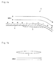
- Fig. 1a there is shown a cross-section of the ionizing material 5.
- the ionizing material 5 is attached to an inner face of the panel 4 to prevent a separation of the airflow from an outer surface of the panel 4.
- the ionizing material 5 is adapted to be charged with the negative potential by an external factor during propulsion of the vehicle 1, and for example, coating material containing tourmaline powder, acrylic resin, polyester resin and so on may be used to form the ionizing material 5.
- coating material containing tourmaline powder, acrylic resin, polyester resin and so on may be used to form the ionizing material 5.
- a length of the ionizing material 5 in the flowing direction of the airflow is longer than a width thereof.
- a longitudinal length of the ionizing material 5 in a flowing direction of the airflow is longer than that of the width thereof.
- the ionizing material 5 may also be arranged on the outer surface of the vehicle body 3.
- the ionizing material 5 may be mixed with coating material applied to the outer surface of the vehicle body 3 or a base coat. In this case, the ionizing material 5 may be applied to the separation point without causing disfigurement of the vehicle 1.
- the vehicle body 3 is charged positively but the ionizing material 5 is charged negatively so that the positive potential of the separation point is decreased by the ionizing material 5 and eventually charged with the negative potential.
- the potential of the separation point is governed by a difference from the negative potential of the ionizing material 5.
- the repulsive force acting between the positively charged airflow and a portion of the panel 4 in the vicinity of the separation point can be reduced by reducing the positive potential of the separation point by the ionizing material 5 even if the separation point is still charged negatively. Then, after the potential of separation point is turned into negative, the airflow will be attracted to the outer surface of the panel 4 due to the Coulomb force.
- separation of the airflow from the outer surface of the vehicle body 3 can be prevented to ensure desired aerodynamic characteristics of the vehicle 1. That is, deterioration in aerodynamic characteristics of the vehicle 1 in the rolling direction and the yawing direction can be prevented.
- the ionizing material 5 can be arranged without changing a surface figure of the vehicle body 3, deterioration in aerodynamic characteristics of the vehicle 1 can be prevented without causing disfigurement of the vehicle 1.
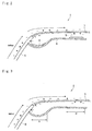
- the ionizing material 5 may be arranged while keeping a distance from the separation point as illustrated in Fig. 2 .
- Fig. 2 is configured to prevent separation of the airflow from a windshield 6 and a roof 7 (although this could be any appropriate part of the vehicle).
- a leading end of the roof 7 is bent downwardly to be connected to the windshield 6, and hence the airflow flowing from the windshield 6 toward the roof 7 has a tendency to deviate from an outer surface of the curved portion of the roof 7.
- a plurality of the ionizing materials 5 are disposed on an inner surface of an inner panel 8 extending from an upper edge of inner surface of the windshield 6 along the roof 7 while keeping a distance to an inner surface of the roof 7. It is noted that there may only be one ionizing material 5.
- one of the ionizing materials 5 is disposed on the inner surface of the inner panel 8 in the vicinity of the upper edge of the inner surface of the windshield 6, and the other ionizing material 5 is disposed on the inner surface of the inner panel 8 at a center of the inner panel 8 in both lengthwise and widthwise.
- a downforce applied to the front wheels is weakened, thereby decreasing control stability.
- the ionizing material 5 may also be formed integrally with the inner panel 8.
- the resin material of the ionizing material 5 may be mixed with fiber material of the inner panel 8.
- Fig. 3 shows such a modification example of another example shown in Fig. 2 , and in this case, the ionizing materials 5 are arranged individually within a region A and a region B.
- the positive potential of the air existing between the separation point and the ionizing material 5 is decreased so that the air will be charged with the negative potential eventually Consequently, the positive potential of the separation point is decreased and the separation point will be charged with the negative potential eventually.
- separation of the airflow from the outer surface of the vehicle body 3 may also be prevented by arranging the ionizing material 5 while keeping a distance from the inner surface of the separation point.
- the ionizing material 5 may also be arranged in a hollow member 9, such as a weather strip.
- various modifications of the ionizing material 5 may be made as desribed.
- the ionizing material 5 may also be integral with other member made of resin, such as an undercover.
- the ionizing material 5 may be mixed with the resin material of an other member, and shaped into a desired shape by an injection molding or an insertion molding.
- the ionizing material 5 may also be arranged in the windshield 6.
- the ionizing material 5 may be mixed with material of an interlayer film. That is, the ionizing material 5 is interposed between glass layers.
- the ionizing material 5 may also be applied to a ceramic coating covering the inner surface of the windshield 6 in the vicinity of the upper edge of the windshield 6 to be covered by a rubber packing.
- the ionizing material 5 may also be applied to a side window. In this case, the ionizing material 5 is applied to a lower edge of the side window at which a surface treatment is not applied. That is, the ionizing material 5 is applied to a portion of the side window at which a surface is rough to avoid a separation therefrom during transportation from a glass factory and during assembly.
Landscapes
- Engineering & Computer Science (AREA)
- Mechanical Engineering (AREA)
- Chemical & Material Sciences (AREA)
- Combustion & Propulsion (AREA)
- Transportation (AREA)
- Physics & Mathematics (AREA)
- Fluid Mechanics (AREA)
- Body Structure For Vehicles (AREA)
- Toxicology (AREA)
- General Health & Medical Sciences (AREA)
- Health & Medical Sciences (AREA)
- Compositions Of Macromolecular Compounds (AREA)
- Paints Or Removers (AREA)
- Elimination Of Static Electricity (AREA)
Abstract

Description
- The present invention claims the benefit of
Japanese Patent Application No. 2015-076643 filed on April 3, 2015 - The present invention relates to the art of an automobile.
-
JP-A-2006-88880 JP-A-2002-104106 - However, the silicon rubber sheet having an uneven surface taught by
JP-A-2006-88880 - The conductive non-woven fabric taught by
JP-A-2002-104106 - Aspects of the present invention have been conceived noting the foregoing technical problems, and it is therefore an object of the present invention to provide a vehicle which can prevent separation of positively charged airflow from a positively charged surface of a vehicle body during propulsion.
- During propulsion of the vehicle, positive static charges accumulate on a vehicle body insulated from a road surface. In order to achieve the above-explained objective, the vehicle according to the present invention is provided with an ionizing material that is charged negatively during propulsion to decrease the positive potential of a separation point at which positively charged airflow flowing along a vehicle surface deviates therefrom during propulsion.
- The ionizing material is formed in such a manner that a length thereof in the flowing direction of the airflow is longer than a width thereof.
- For example, the ionizing material may be integrated with the separation point.
- The separation point may be formed of resin material. In this case, the ionizing material may be integrated with the separation point.
- The vehicle further comprises an inner panel extending along an inner surface of the vehicle body while keeping a predetermined distance, and the ionizing material may be integrated with the inner panel.
- For example, resin material may be used as the ionizing material.
- The ionizing material may also be mixed with coating material applied to the separation point.
- Thus, according to the present invention, the vehicle is provided with the ionizing material that is charged negatively during propulsion to decrease the positive potential of a separation point at which positively charged airflow flowing along a vehicle surface deviates therefrom during propulsion. According to the present invention, therefore, repulsive force acting between the positively charged airflow and the positively charged vehicle surface can be reduced to prevent separation of the airflow from the vehicle surface during propulsion of the vehicle. For this reason, desired aerodynamic characteristics of the vehicle can be ensured to improve a traveling stability of the vehicle.
- Features, aspects, and advantages of exemplary embodiments of the present invention will become better understood with reference to the following description and accompanying drawings, which should not limit the invention in any way.
-
Fig. 1a is an explanatory illustration showing an ionizing material according to the preferred example attached to an inner face of the vehicle; -
Fig. 1b is a top view of the ionizing material shown inFig. 1a ; -
Fig. 2 is a cross-sectional view showing the ionizing material attached to an inner panel; -
Fig. 3 is a cross-sectional view showing the inner panel formed integrally with the ionizing material; -
Fig. 4 is a cross-sectional view showing the ionizing material held in a hollow member; -
Fig. 5 is a perspective view showing one example of a vehicle to which the present invention is applied; and -
Fig. 6 is a graph indicating measurement results of flow velocity distributions in a direction perpendicular to a surface of a model vehicle. - Referring now to
Fig. 5 , there is shown one example of a vehicle to which the present invention is applied. In thevehicle 1, a tire made of insulating material whose electrical conductivity is small such as rubber is individually mounted on eachwheel 2 to insulate avehicle body 3 from a road surface. During propulsion of thevehicle 1, positive static charges may accumulate on abody 3 for a variety of reasons, e.g., friction between a surface of thebody 3 and an external airstream or friction between an air duct and air flowing therethrough. The positive static charges may also accumulate on thebody 3 due to friction between slidable members of a prime mover such as an engine and a motor, a transmission, a suspension, etc.. The positive static charges may also accumulate on thebody 3 due to of friction between the tire and the road surface, and an electrical spark resulting from detachment of the tire from the road surface. In addition, the positive static charges may also accumulate on thebody 3 due to of electrical activity of electrical equipment and/or an influence of external electrical cables, etc.. - Static electricity may also accumulate on other parts of the body and panels made of material of relatively high electrical conductivity for a reason of electrical resistance at a joint portion.
- Air is charged positively and hence repulsive force acts between the air and the
body 3 on which the positive charges accumulate. Turning toFig. 6 , there are shown measurement results of flow velocity distribution in a direction perpendicular to a positively charged surface of a model vehicle, and flow velocity distribution in a direction perpendicular to an uncharged surface of a model vehicle. InFig.6 , the vertical axis represents a distance from the surface of the model vehicle, and the horizontal axis represents a ratio (U/ U∞) of a flow velocity U of the air flowing on the surface of the model vehicle to a flow velocity U∞ measured from a predetermined distance. Square dots represent measured values of flow velocity of the air flowing on the positively charged surface of the model vehicle, and rhombus dots represent measured values of flow velocity of the air flowing on the uncharged surface of the model vehicle. - As can be seen from
Fig. 6 , a thickness of a boundary layer (i.e., a distance from the vehicle surface at which the ratio U/ U∞ is substantially zero) when the surface of the model vehicle is positively charged is thicker than a thickness of the boundary layer when the surface of the model vehicle is not charged. This means that the airflow is isolated further away from the positively charged surface of the model vehicle in comparison with the case in which the surface is not charged. This is because the airflow is charged positively and hence the positively charged airflow and the positively charged surface of the vehicle repel each other. - During propulsion of the
vehicle 1, the airflow flowing along the surface of thebody 3 have a tendency to deviate from the surface of thebody 3 at specific points. Specifically, the airflow deviates from the surface of thebody 3 at a portion where thebody 3 is bent inwardly or protruded outwardly. For example, the airflow has a tendency to deviate from the surface of thebody 3 at depressions on a bonnet, a roof, and side members. In addition, the airflow also deviates from an outer surface of an undercover at corners between a downwardly slanted plate and a flat plate, and between the flat plate and an upwardly slanted plate. Those points at which the airflow deviates from the surface of thebody 3 will be called the "separation point" in the following description and claims. - The airflow is attracted to the surface of the
body 3 by the Coanda effect in accordance with a speed difference between the airflow and thevehicle body 3 even at the above-mentioned separation points. However, given that thebody 3 is charged positively, the positively charged airflow is repelled therefrom. In order to avoid such separation of the airflow from the vehicle body, according to the preferred example, the separation points are found by an experiment conducted in a wind tunnel, and the positive potential of the specified separation point is decreased or the separation point is charged negatively by an ionizing material attached thereto. - Turning to
Fig. 1a , there is shown a cross-section of the ionizingmaterial 5. In thevehicle 1, an upstream side of apanel 4 is formed into a flat wall but a downstream side thereof is curved inwardly which forms the above-mentioned separation point. According to the preferred example, the ionizingmaterial 5 is attached to an inner face of thepanel 4 to prevent a separation of the airflow from an outer surface of thepanel 4. The ionizingmaterial 5 is adapted to be charged with the negative potential by an external factor during propulsion of thevehicle 1, and for example, coating material containing tourmaline powder, acrylic resin, polyester resin and so on may be used to form the ionizingmaterial 5. As illustrated inFig. 1b , it is preferable to form the ionizingmaterial 5 in such a manner that a length of the ionizingmaterial 5 in the flowing direction of the airflow is longer than a width thereof. In other words, a longitudinal length of the ionizingmaterial 5 in a flowing direction of the airflow is longer than that of the width thereof. - Alternatively or additionally, the ionizing
material 5 may also be arranged on the outer surface of thevehicle body 3. For example, the ionizingmaterial 5 may be mixed with coating material applied to the outer surface of thevehicle body 3 or a base coat. In this case, the ionizingmaterial 5 may be applied to the separation point without causing disfigurement of thevehicle 1. - During propulsion of the
vehicle 1, thevehicle body 3 is charged positively but theionizing material 5 is charged negatively so that the positive potential of the separation point is decreased by the ionizingmaterial 5 and eventually charged with the negative potential. In this situation, the potential of the separation point is governed by a difference from the negative potential of theionizing material 5. According to the preferred example, the repulsive force acting between the positively charged airflow and a portion of thepanel 4 in the vicinity of the separation point can be reduced by reducing the positive potential of the separation point by the ionizingmaterial 5 even if the separation point is still charged negatively. Then, after the potential of separation point is turned into negative, the airflow will be attracted to the outer surface of thepanel 4 due to the Coulomb force. - Thus, according to the preferred example, separation of the airflow from the outer surface of the
vehicle body 3 can be prevented to ensure desired aerodynamic characteristics of thevehicle 1. That is, deterioration in aerodynamic characteristics of thevehicle 1 in the rolling direction and the yawing direction can be prevented. In addition, since theionizing material 5 can be arranged without changing a surface figure of thevehicle body 3, deterioration in aerodynamic characteristics of thevehicle 1 can be prevented without causing disfigurement of thevehicle 1. - According to another example, the ionizing
material 5 may be arranged while keeping a distance from the separation point as illustrated inFig. 2 . Specifically, another example shown inFig. 2 is configured to prevent separation of the airflow from awindshield 6 and a roof 7 (although this could be any appropriate part of the vehicle). In thevehicle 1 shown therein, a leading end of theroof 7 is bent downwardly to be connected to thewindshield 6, and hence the airflow flowing from thewindshield 6 toward theroof 7 has a tendency to deviate from an outer surface of the curved portion of theroof 7. According to the example shown inFig. 2 , a plurality of theionizing materials 5 are disposed on an inner surface of aninner panel 8 extending from an upper edge of inner surface of thewindshield 6 along theroof 7 while keeping a distance to an inner surface of theroof 7. It is noted that there may only be one ionizingmaterial 5. - In order to effectively prevent such separation of the airflow, specifically, one of the
ionizing materials 5 is disposed on the inner surface of theinner panel 8 in the vicinity of the upper edge of the inner surface of thewindshield 6, and the otherionizing material 5 is disposed on the inner surface of theinner panel 8 at a center of theinner panel 8 in both lengthwise and widthwise. - If the separation of airflow is caused at a front side of the
vehicle 1, a downforce applied to the front wheels is weakened, thereby decreasing control stability. In order to avoid such disadvantage, it is further preferable to arrange a plurality of theionizing materials 5 on the inner surface of theinner panel 8 along the upper edge of the inner surface of thewindshield 6 at predetermined intervals in the width direction. - The
ionizing material 5 may also be formed integrally with theinner panel 8. For example, the resin material of theionizing material 5 may be mixed with fiber material of theinner panel 8.Fig. 3 shows such a modification example of another example shown inFig. 2 , and in this case, theionizing materials 5 are arranged individually within a region A and a region B. - According to the example shown in
Fig. 3 , the positive potential of the air existing between the separation point and theionizing material 5 is decreased so that the air will be charged with the negative potential eventually Consequently, the positive potential of the separation point is decreased and the separation point will be charged with the negative potential eventually. Thus, separation of the airflow from the outer surface of thevehicle body 3 may also be prevented by arranging theionizing material 5 while keeping a distance from the inner surface of the separation point. - In addition, since the separation of the airflow from the width center of the outer surface of the
roof 7 is thus prevented, turning performance and travelling stability of thevehicle 1 can be ensured. Specifically, even when thevehicle 1 making a turn receives air diagonally, the difference between downforces at the inner wheel side and the outer wheel side can be reduced to improve a turning performance of thevehicle 1. - As illustrated in
Fig. 4 , the ionizingmaterial 5 may also be arranged in ahollow member 9, such as a weather strip. Likewise, various modifications of theionizing material 5 may be made as desribed. For example, the ionizingmaterial 5 may also be integral with other member made of resin, such as an undercover. Theionizing material 5 may be mixed with the resin material of an other member, and shaped into a desired shape by an injection molding or an insertion molding. Further, the ionizingmaterial 5 may also be arranged in thewindshield 6. In this case, specifically, the ionizingmaterial 5 may be mixed with material of an interlayer film. That is, the ionizingmaterial 5 is interposed between glass layers. - In addition, the ionizing
material 5 may also be applied to a ceramic coating covering the inner surface of thewindshield 6 in the vicinity of the upper edge of thewindshield 6 to be covered by a rubber packing. In order to prevent separation of airflow from a side face of the vehicle at a front pillar or a center pillar, the ionizingmaterial 5 may also be applied to a side window. In this case, the ionizingmaterial 5 is applied to a lower edge of the side window at which a surface treatment is not applied. That is, the ionizingmaterial 5 is applied to a portion of the side window at which a surface is rough to avoid a separation therefrom during transportation from a glass factory and during assembly.
Claims (7)
- A vehicle (1), in which positive static charges accumulate on a vehicle body (3) insulated from a road surface during propulsion,
characterized in that the vehicle comprises:an ionizing material (5) that is charged negatively during propulsion to decrease the positive potential of a separation point at which positively charged airflow flowing along a vehicle surface deviates therefrom during propulsion. - The vehicle as claimed in claim 1, in which a length of the ionizing material in the flowing direction of the airflow is longer than a width thereof.
- The vehicle (1) as claimed in claim 1 or 2, wherein the ionizing material (5) is integrated with the separation point.
- The vehicle (1) as claimed in claim 3,
wherein the separation point is formed of resin material. - The vehicle as claimed in claim 1 or 2, further comprising:an inner panel (8) extending along an inner surface of the vehicle body (3) while keeping a predetermined distance; andwherein at least one of the ionizing material (5) is integrated with the inner panel (8), or the ionizing material is attached to the inner panel.
- The vehicle (1) as claimed in any of claims 1 to 5, wherein the ionizing material (5) includes resin material.
- The vehicle (1) as claimed in any of claims 1 to6, wherein the ionizing material (5) is mixed with coating material applied to the separation point.
Applications Claiming Priority (1)
| Application Number | Priority Date | Filing Date | Title |
|---|---|---|---|
| JP2015076643A JP6344292B2 (en) | 2015-04-03 | 2015-04-03 | vehicle |
Publications (2)
| Publication Number | Publication Date |
|---|---|
| EP3075654A1 true EP3075654A1 (en) | 2016-10-05 |
| EP3075654B1 EP3075654B1 (en) | 2018-09-12 |
Family
ID=55587093
Family Applications (1)
| Application Number | Title | Priority Date | Filing Date |
|---|---|---|---|
| EP16160448.3A Not-in-force EP3075654B1 (en) | 2015-04-03 | 2016-03-15 | Vehicle with ionising material |
Country Status (5)
| Country | Link |
|---|---|
| US (1) | US10053161B2 (en) |
| EP (1) | EP3075654B1 (en) |
| JP (1) | JP6344292B2 (en) |
| KR (1) | KR101827904B1 (en) |
| CN (1) | CN106043180B (en) |
Families Citing this family (6)
| Publication number | Priority date | Publication date | Assignee | Title |
|---|---|---|---|---|
| JP6344292B2 (en) * | 2015-04-03 | 2018-06-20 | トヨタ自動車株式会社 | vehicle |
| JP6597700B2 (en) * | 2017-04-13 | 2019-10-30 | トヨタ自動車株式会社 | Vehicle static eliminator |
| JP7050600B2 (en) * | 2018-07-09 | 2022-04-08 | トヨタ自動車株式会社 | Static eliminator for vehicles and vehicles |
| DE102019133504B4 (en) * | 2019-12-09 | 2025-11-27 | Dr. Ing. H.C. F. Porsche Aktiengesellschaft | Motor vehicle body with a plasma actuator |
| JP7367642B2 (en) * | 2020-09-10 | 2023-10-24 | トヨタ自動車株式会社 | Vehicles and static elimination parts |
| JP2023158329A (en) * | 2022-04-18 | 2023-10-30 | トヨタ自動車株式会社 | Vehicle exterior structure |
Citations (8)
| Publication number | Priority date | Publication date | Assignee | Title |
|---|---|---|---|---|
| JP2002104106A (en) | 2000-09-27 | 2002-04-10 | Achilles Corp | Static eliminator of industrial vehicle |
| JP2006088880A (en) | 2004-09-24 | 2006-04-06 | Corrmann Inc | Air current separation reducing sheet |
| JP2007317656A (en) * | 2006-04-28 | 2007-12-06 | Toshiba Corp | Airflow generation device, airflow generation unit, blade, heat exchange device, micromachine, gas processing device, airflow generation method, and airflow control method |
| JP2008143476A (en) * | 2006-12-13 | 2008-06-26 | Toyota Motor Corp | Air resistance reduction device |
| JP2010179829A (en) * | 2009-02-06 | 2010-08-19 | Toshiba Corp | vehicle |
| WO2012115204A1 (en) * | 2011-02-23 | 2012-08-30 | 京セラ株式会社 | Ion wind generator and ion wind generating device |
| EP2781739A2 (en) * | 2013-03-21 | 2014-09-24 | Kabushiki Kaisha Toshiba | Avoidance of wind turbine blade leading edge flow separation |
| EP3037288A1 (en) * | 2014-12-26 | 2016-06-29 | Toyota Jidosha Kabushiki Kaisha | Vehicle |
Family Cites Families (13)
| Publication number | Priority date | Publication date | Assignee | Title |
|---|---|---|---|---|
| JP2002011834A (en) * | 2000-06-30 | 2002-01-15 | Sekaicho Rubber Co Ltd | Multifunctional sheet / film member |
| JP2002309481A (en) * | 2001-04-11 | 2002-10-23 | Toray Ind Inc | Vehicle interior |
| US7318619B2 (en) * | 2004-01-12 | 2008-01-15 | Munro & Associates | Method and apparatus for reducing drag and noise for a vehicle |
| CA2668450A1 (en) * | 2006-11-02 | 2008-05-15 | The University Of Notre Dame Du Lac | Methods and apparatus for reducing drag via a plasma actuator |
| US7735910B2 (en) * | 2007-03-10 | 2010-06-15 | Honda Motor Co., Ltd | Plasma wind deflector for a sunroof |
| US10336270B2 (en) * | 2013-10-30 | 2019-07-02 | Toyota Jidosha Kabushiki Kaisha | Vehicle and manufacturing method thereof |
| JP6128093B2 (en) * | 2014-10-16 | 2017-05-17 | トヨタ自動車株式会社 | Vehicle intake system |
| JP6160603B2 (en) * | 2014-12-19 | 2017-07-12 | トヨタ自動車株式会社 | Vehicle cooling device |
| JP6201980B2 (en) * | 2014-12-25 | 2017-09-27 | トヨタ自動車株式会社 | Vehicle intake system |
| JP6115559B2 (en) * | 2014-12-26 | 2017-04-19 | トヨタ自動車株式会社 | Vehicle exhaust system |
| JP6146405B2 (en) * | 2014-12-26 | 2017-06-14 | トヨタ自動車株式会社 | Engine and engine manufacturing method |
| JP6217675B2 (en) * | 2015-03-13 | 2017-10-25 | トヨタ自動車株式会社 | vehicle |
| JP6344292B2 (en) * | 2015-04-03 | 2018-06-20 | トヨタ自動車株式会社 | vehicle |
-
2015
- 2015-04-03 JP JP2015076643A patent/JP6344292B2/en active Active
-
2016
- 2016-03-15 EP EP16160448.3A patent/EP3075654B1/en not_active Not-in-force
- 2016-04-01 CN CN201610204060.4A patent/CN106043180B/en active Active
- 2016-04-01 KR KR1020160040412A patent/KR101827904B1/en active Active
- 2016-04-01 US US15/088,715 patent/US10053161B2/en active Active
Patent Citations (8)
| Publication number | Priority date | Publication date | Assignee | Title |
|---|---|---|---|---|
| JP2002104106A (en) | 2000-09-27 | 2002-04-10 | Achilles Corp | Static eliminator of industrial vehicle |
| JP2006088880A (en) | 2004-09-24 | 2006-04-06 | Corrmann Inc | Air current separation reducing sheet |
| JP2007317656A (en) * | 2006-04-28 | 2007-12-06 | Toshiba Corp | Airflow generation device, airflow generation unit, blade, heat exchange device, micromachine, gas processing device, airflow generation method, and airflow control method |
| JP2008143476A (en) * | 2006-12-13 | 2008-06-26 | Toyota Motor Corp | Air resistance reduction device |
| JP2010179829A (en) * | 2009-02-06 | 2010-08-19 | Toshiba Corp | vehicle |
| WO2012115204A1 (en) * | 2011-02-23 | 2012-08-30 | 京セラ株式会社 | Ion wind generator and ion wind generating device |
| EP2781739A2 (en) * | 2013-03-21 | 2014-09-24 | Kabushiki Kaisha Toshiba | Avoidance of wind turbine blade leading edge flow separation |
| EP3037288A1 (en) * | 2014-12-26 | 2016-06-29 | Toyota Jidosha Kabushiki Kaisha | Vehicle |
Also Published As
| Publication number | Publication date |
|---|---|
| US20160288844A1 (en) | 2016-10-06 |
| JP6344292B2 (en) | 2018-06-20 |
| CN106043180B (en) | 2019-06-18 |
| CN106043180A (en) | 2016-10-26 |
| KR20160118985A (en) | 2016-10-12 |
| KR101827904B1 (en) | 2018-02-09 |
| US10053161B2 (en) | 2018-08-21 |
| JP2016196232A (en) | 2016-11-24 |
| EP3075654B1 (en) | 2018-09-12 |
Similar Documents
| Publication | Publication Date | Title |
|---|---|---|
| US10053161B2 (en) | Vehicle | |
| EP3064416B1 (en) | Vehicle, and method of manufacturing same | |
| US10207750B2 (en) | Vehicle | |
| EP3037288B1 (en) | Vehicle | |
| US11447083B2 (en) | Vehicle and electrostatic elimination component | |
| US10988093B2 (en) | Vehicular static eliminating device and vehicle | |
| US11192406B2 (en) | Neutralization device for vehicles | |
| JP2022046037A (en) | vehicle | |
| JP2019192568A (en) | Static eliminator for vehicle |
Legal Events
| Date | Code | Title | Description |
|---|---|---|---|
| PUAI | Public reference made under article 153(3) epc to a published international application that has entered the european phase |
Free format text: ORIGINAL CODE: 0009012 |
|
| 17P | Request for examination filed |
Effective date: 20160315 |
|
| AK | Designated contracting states |
Kind code of ref document: A1 Designated state(s): AL AT BE BG CH CY CZ DE DK EE ES FI FR GB GR HR HU IE IS IT LI LT LU LV MC MK MT NL NO PL PT RO RS SE SI SK SM TR |
|
| AX | Request for extension of the european patent |
Extension state: BA ME |
|
| GRAP | Despatch of communication of intention to grant a patent |
Free format text: ORIGINAL CODE: EPIDOSNIGR1 |
|
| STAA | Information on the status of an ep patent application or granted ep patent |
Free format text: STATUS: GRANT OF PATENT IS INTENDED |
|
| RIC1 | Information provided on ipc code assigned before grant |
Ipc: B64C 23/00 20060101AFI20180301BHEP |
|
| INTG | Intention to grant announced |
Effective date: 20180329 |
|
| GRAS | Grant fee paid |
Free format text: ORIGINAL CODE: EPIDOSNIGR3 |
|
| GRAA | (expected) grant |
Free format text: ORIGINAL CODE: 0009210 |
|
| STAA | Information on the status of an ep patent application or granted ep patent |
Free format text: STATUS: THE PATENT HAS BEEN GRANTED |
|
| AK | Designated contracting states |
Kind code of ref document: B1 Designated state(s): AL AT BE BG CH CY CZ DE DK EE ES FI FR GB GR HR HU IE IS IT LI LT LU LV MC MK MT NL NO PL PT RO RS SE SI SK SM TR |
|
| REG | Reference to a national code |
Ref country code: GB Ref legal event code: FG4D |
|
| REG | Reference to a national code |
Ref country code: CH Ref legal event code: EP |
|
| REG | Reference to a national code |
Ref country code: IE Ref legal event code: FG4D |
|
| REG | Reference to a national code |
Ref country code: DE Ref legal event code: R096 Ref document number: 602016005421 Country of ref document: DE |
|
| REG | Reference to a national code |
Ref country code: AT Ref legal event code: REF Ref document number: 1040237 Country of ref document: AT Kind code of ref document: T Effective date: 20181015 |
|
| REG | Reference to a national code |
Ref country code: DE Ref legal event code: R084 Ref document number: 602016005421 Country of ref document: DE |
|
| REG | Reference to a national code |
Ref country code: GB Ref legal event code: 746 Effective date: 20181126 |
|
| REG | Reference to a national code |
Ref country code: NL Ref legal event code: MP Effective date: 20180912 |
|
| REG | Reference to a national code |
Ref country code: LT Ref legal event code: MG4D |
|
| PG25 | Lapsed in a contracting state [announced via postgrant information from national office to epo] |
Ref country code: RS Free format text: LAPSE BECAUSE OF FAILURE TO SUBMIT A TRANSLATION OF THE DESCRIPTION OR TO PAY THE FEE WITHIN THE PRESCRIBED TIME-LIMIT Effective date: 20180912 Ref country code: LT Free format text: LAPSE BECAUSE OF FAILURE TO SUBMIT A TRANSLATION OF THE DESCRIPTION OR TO PAY THE FEE WITHIN THE PRESCRIBED TIME-LIMIT Effective date: 20180912 Ref country code: GR Free format text: LAPSE BECAUSE OF FAILURE TO SUBMIT A TRANSLATION OF THE DESCRIPTION OR TO PAY THE FEE WITHIN THE PRESCRIBED TIME-LIMIT Effective date: 20181213 Ref country code: FI Free format text: LAPSE BECAUSE OF FAILURE TO SUBMIT A TRANSLATION OF THE DESCRIPTION OR TO PAY THE FEE WITHIN THE PRESCRIBED TIME-LIMIT Effective date: 20180912 Ref country code: SE Free format text: LAPSE BECAUSE OF FAILURE TO SUBMIT A TRANSLATION OF THE DESCRIPTION OR TO PAY THE FEE WITHIN THE PRESCRIBED TIME-LIMIT Effective date: 20180912 Ref country code: NO Free format text: LAPSE BECAUSE OF FAILURE TO SUBMIT A TRANSLATION OF THE DESCRIPTION OR TO PAY THE FEE WITHIN THE PRESCRIBED TIME-LIMIT Effective date: 20181212 Ref country code: BG Free format text: LAPSE BECAUSE OF FAILURE TO SUBMIT A TRANSLATION OF THE DESCRIPTION OR TO PAY THE FEE WITHIN THE PRESCRIBED TIME-LIMIT Effective date: 20181212 |
|
| PG25 | Lapsed in a contracting state [announced via postgrant information from national office to epo] |
Ref country code: HR Free format text: LAPSE BECAUSE OF FAILURE TO SUBMIT A TRANSLATION OF THE DESCRIPTION OR TO PAY THE FEE WITHIN THE PRESCRIBED TIME-LIMIT Effective date: 20180912 Ref country code: LV Free format text: LAPSE BECAUSE OF FAILURE TO SUBMIT A TRANSLATION OF THE DESCRIPTION OR TO PAY THE FEE WITHIN THE PRESCRIBED TIME-LIMIT Effective date: 20180912 Ref country code: AL Free format text: LAPSE BECAUSE OF FAILURE TO SUBMIT A TRANSLATION OF THE DESCRIPTION OR TO PAY THE FEE WITHIN THE PRESCRIBED TIME-LIMIT Effective date: 20180912 |
|
| REG | Reference to a national code |
Ref country code: AT Ref legal event code: MK05 Ref document number: 1040237 Country of ref document: AT Kind code of ref document: T Effective date: 20180912 |
|
| PG25 | Lapsed in a contracting state [announced via postgrant information from national office to epo] |
Ref country code: IT Free format text: LAPSE BECAUSE OF FAILURE TO SUBMIT A TRANSLATION OF THE DESCRIPTION OR TO PAY THE FEE WITHIN THE PRESCRIBED TIME-LIMIT Effective date: 20180912 Ref country code: ES Free format text: LAPSE BECAUSE OF FAILURE TO SUBMIT A TRANSLATION OF THE DESCRIPTION OR TO PAY THE FEE WITHIN THE PRESCRIBED TIME-LIMIT Effective date: 20180912 Ref country code: CZ Free format text: LAPSE BECAUSE OF FAILURE TO SUBMIT A TRANSLATION OF THE DESCRIPTION OR TO PAY THE FEE WITHIN THE PRESCRIBED TIME-LIMIT Effective date: 20180912 Ref country code: NL Free format text: LAPSE BECAUSE OF FAILURE TO SUBMIT A TRANSLATION OF THE DESCRIPTION OR TO PAY THE FEE WITHIN THE PRESCRIBED TIME-LIMIT Effective date: 20180912 Ref country code: RO Free format text: LAPSE BECAUSE OF FAILURE TO SUBMIT A TRANSLATION OF THE DESCRIPTION OR TO PAY THE FEE WITHIN THE PRESCRIBED TIME-LIMIT Effective date: 20180912 Ref country code: AT Free format text: LAPSE BECAUSE OF FAILURE TO SUBMIT A TRANSLATION OF THE DESCRIPTION OR TO PAY THE FEE WITHIN THE PRESCRIBED TIME-LIMIT Effective date: 20180912 Ref country code: EE Free format text: LAPSE BECAUSE OF FAILURE TO SUBMIT A TRANSLATION OF THE DESCRIPTION OR TO PAY THE FEE WITHIN THE PRESCRIBED TIME-LIMIT Effective date: 20180912 Ref country code: IS Free format text: LAPSE BECAUSE OF FAILURE TO SUBMIT A TRANSLATION OF THE DESCRIPTION OR TO PAY THE FEE WITHIN THE PRESCRIBED TIME-LIMIT Effective date: 20190112 Ref country code: PL Free format text: LAPSE BECAUSE OF FAILURE TO SUBMIT A TRANSLATION OF THE DESCRIPTION OR TO PAY THE FEE WITHIN THE PRESCRIBED TIME-LIMIT Effective date: 20180912 |
|
| PG25 | Lapsed in a contracting state [announced via postgrant information from national office to epo] |
Ref country code: SK Free format text: LAPSE BECAUSE OF FAILURE TO SUBMIT A TRANSLATION OF THE DESCRIPTION OR TO PAY THE FEE WITHIN THE PRESCRIBED TIME-LIMIT Effective date: 20180912 Ref country code: SM Free format text: LAPSE BECAUSE OF FAILURE TO SUBMIT A TRANSLATION OF THE DESCRIPTION OR TO PAY THE FEE WITHIN THE PRESCRIBED TIME-LIMIT Effective date: 20180912 Ref country code: PT Free format text: LAPSE BECAUSE OF FAILURE TO SUBMIT A TRANSLATION OF THE DESCRIPTION OR TO PAY THE FEE WITHIN THE PRESCRIBED TIME-LIMIT Effective date: 20190112 |
|
| REG | Reference to a national code |
Ref country code: DE Ref legal event code: R097 Ref document number: 602016005421 Country of ref document: DE |
|
| PLBE | No opposition filed within time limit |
Free format text: ORIGINAL CODE: 0009261 |
|
| STAA | Information on the status of an ep patent application or granted ep patent |
Free format text: STATUS: NO OPPOSITION FILED WITHIN TIME LIMIT |
|
| PG25 | Lapsed in a contracting state [announced via postgrant information from national office to epo] |
Ref country code: DK Free format text: LAPSE BECAUSE OF FAILURE TO SUBMIT A TRANSLATION OF THE DESCRIPTION OR TO PAY THE FEE WITHIN THE PRESCRIBED TIME-LIMIT Effective date: 20180912 |
|
| 26N | No opposition filed |
Effective date: 20190613 |
|
| PG25 | Lapsed in a contracting state [announced via postgrant information from national office to epo] |
Ref country code: SI Free format text: LAPSE BECAUSE OF FAILURE TO SUBMIT A TRANSLATION OF THE DESCRIPTION OR TO PAY THE FEE WITHIN THE PRESCRIBED TIME-LIMIT Effective date: 20180912 |
|
| PG25 | Lapsed in a contracting state [announced via postgrant information from national office to epo] |
Ref country code: MC Free format text: LAPSE BECAUSE OF FAILURE TO SUBMIT A TRANSLATION OF THE DESCRIPTION OR TO PAY THE FEE WITHIN THE PRESCRIBED TIME-LIMIT Effective date: 20180912 |
|
| REG | Reference to a national code |
Ref country code: CH Ref legal event code: PL |
|
| PG25 | Lapsed in a contracting state [announced via postgrant information from national office to epo] |
Ref country code: LU Free format text: LAPSE BECAUSE OF NON-PAYMENT OF DUE FEES Effective date: 20190315 |
|
| REG | Reference to a national code |
Ref country code: BE Ref legal event code: MM Effective date: 20190331 |
|
| PG25 | Lapsed in a contracting state [announced via postgrant information from national office to epo] |
Ref country code: CH Free format text: LAPSE BECAUSE OF NON-PAYMENT OF DUE FEES Effective date: 20190331 Ref country code: IE Free format text: LAPSE BECAUSE OF NON-PAYMENT OF DUE FEES Effective date: 20190315 Ref country code: LI Free format text: LAPSE BECAUSE OF NON-PAYMENT OF DUE FEES Effective date: 20190331 |
|
| PG25 | Lapsed in a contracting state [announced via postgrant information from national office to epo] |
Ref country code: BE Free format text: LAPSE BECAUSE OF NON-PAYMENT OF DUE FEES Effective date: 20190331 |
|
| PG25 | Lapsed in a contracting state [announced via postgrant information from national office to epo] |
Ref country code: TR Free format text: LAPSE BECAUSE OF FAILURE TO SUBMIT A TRANSLATION OF THE DESCRIPTION OR TO PAY THE FEE WITHIN THE PRESCRIBED TIME-LIMIT Effective date: 20180912 |
|
| PG25 | Lapsed in a contracting state [announced via postgrant information from national office to epo] |
Ref country code: MT Free format text: LAPSE BECAUSE OF NON-PAYMENT OF DUE FEES Effective date: 20190315 |
|
| PG25 | Lapsed in a contracting state [announced via postgrant information from national office to epo] |
Ref country code: CY Free format text: LAPSE BECAUSE OF FAILURE TO SUBMIT A TRANSLATION OF THE DESCRIPTION OR TO PAY THE FEE WITHIN THE PRESCRIBED TIME-LIMIT Effective date: 20180912 |
|
| PG25 | Lapsed in a contracting state [announced via postgrant information from national office to epo] |
Ref country code: HU Free format text: LAPSE BECAUSE OF FAILURE TO SUBMIT A TRANSLATION OF THE DESCRIPTION OR TO PAY THE FEE WITHIN THE PRESCRIBED TIME-LIMIT; INVALID AB INITIO Effective date: 20160315 |
|
| PG25 | Lapsed in a contracting state [announced via postgrant information from national office to epo] |
Ref country code: MK Free format text: LAPSE BECAUSE OF FAILURE TO SUBMIT A TRANSLATION OF THE DESCRIPTION OR TO PAY THE FEE WITHIN THE PRESCRIBED TIME-LIMIT Effective date: 20180912 |
|
| PGFP | Annual fee paid to national office [announced via postgrant information from national office to epo] |
Ref country code: FR Payment date: 20230208 Year of fee payment: 8 |
|
| PGFP | Annual fee paid to national office [announced via postgrant information from national office to epo] |
Ref country code: GB Payment date: 20230202 Year of fee payment: 8 Ref country code: DE Payment date: 20230131 Year of fee payment: 8 |
|
| P01 | Opt-out of the competence of the unified patent court (upc) registered |
Effective date: 20230427 |
|
| REG | Reference to a national code |
Ref country code: DE Ref legal event code: R119 Ref document number: 602016005421 Country of ref document: DE |
|
| GBPC | Gb: european patent ceased through non-payment of renewal fee |
Effective date: 20240315 |
|
| PG25 | Lapsed in a contracting state [announced via postgrant information from national office to epo] |
Ref country code: DE Free format text: LAPSE BECAUSE OF NON-PAYMENT OF DUE FEES Effective date: 20241001 |
|
| PG25 | Lapsed in a contracting state [announced via postgrant information from national office to epo] |
Ref country code: GB Free format text: LAPSE BECAUSE OF NON-PAYMENT OF DUE FEES Effective date: 20240315 |
|
| PG25 | Lapsed in a contracting state [announced via postgrant information from national office to epo] |
Ref country code: FR Free format text: LAPSE BECAUSE OF NON-PAYMENT OF DUE FEES Effective date: 20240331 |
|
| PG25 | Lapsed in a contracting state [announced via postgrant information from national office to epo] |
Ref country code: GB Free format text: LAPSE BECAUSE OF NON-PAYMENT OF DUE FEES Effective date: 20240315 Ref country code: FR Free format text: LAPSE BECAUSE OF NON-PAYMENT OF DUE FEES Effective date: 20240331 Ref country code: DE Free format text: LAPSE BECAUSE OF NON-PAYMENT OF DUE FEES Effective date: 20241001 |