EP3075513A1 - Injection molding machine - Google Patents
Injection molding machine Download PDFInfo
- Publication number
- EP3075513A1 EP3075513A1 EP16161128.0A EP16161128A EP3075513A1 EP 3075513 A1 EP3075513 A1 EP 3075513A1 EP 16161128 A EP16161128 A EP 16161128A EP 3075513 A1 EP3075513 A1 EP 3075513A1
- Authority
- EP
- European Patent Office
- Prior art keywords
- platen
- mold
- body part
- frame
- stationary
- Prior art date
- Legal status (The legal status is an assumption and is not a legal conclusion. Google has not performed a legal analysis and makes no representation as to the accuracy of the status listed.)
- Granted
Links
Images

Classifications
-
- B—PERFORMING OPERATIONS; TRANSPORTING
- B29—WORKING OF PLASTICS; WORKING OF SUBSTANCES IN A PLASTIC STATE IN GENERAL
- B29C—SHAPING OR JOINING OF PLASTICS; SHAPING OF MATERIAL IN A PLASTIC STATE, NOT OTHERWISE PROVIDED FOR; AFTER-TREATMENT OF THE SHAPED PRODUCTS, e.g. REPAIRING
- B29C45/00—Injection moulding, i.e. forcing the required volume of moulding material through a nozzle into a closed mould; Apparatus therefor
- B29C45/17—Component parts, details or accessories; Auxiliary operations
- B29C45/1742—Mounting of moulds; Mould supports
- B29C45/1744—Mould support platens
-
- B—PERFORMING OPERATIONS; TRANSPORTING
- B29—WORKING OF PLASTICS; WORKING OF SUBSTANCES IN A PLASTIC STATE IN GENERAL
- B29C—SHAPING OR JOINING OF PLASTICS; SHAPING OF MATERIAL IN A PLASTIC STATE, NOT OTHERWISE PROVIDED FOR; AFTER-TREATMENT OF THE SHAPED PRODUCTS, e.g. REPAIRING
- B29C45/00—Injection moulding, i.e. forcing the required volume of moulding material through a nozzle into a closed mould; Apparatus therefor
- B29C45/17—Component parts, details or accessories; Auxiliary operations
- B29C45/64—Mould opening, closing or clamping devices
- B29C45/66—Mould opening, closing or clamping devices mechanical
- B29C45/661—Mould opening, closing or clamping devices mechanical using a toggle mechanism for mould clamping
Definitions
- the present invention relates to an injection molding machine.
- Injection molding machines have a mold clamping unit that performs mold opening, mold clamping, and mold closing of a mold unit, and a frame that supports the mold clamping unit (for example, refer to Japanese Unexamined Patent Application Publication No. 2002-337184 ).
- the mold unit is configured to include a stationary mold and a movable mold.
- the mold clamping unit has a stationary platen to which the stationary mold is attached, a movable platen to which the movable mold is attached, and a rear platen coupled to the stationary platen at a distance therefrom via tie-bars.
- the movable platen is disposed between the stationary platen and the rear platen.
- One of the stationary platen and the rear platen is fixed to the frame.
- the mold clamping unit moves the movable platen to the stationary platen, thereby performing mold closing, mold clamping, and mold opening of the mold unit.
- the platen fixed to the frame may be tilted due to the operation of the mold clamping unit, and a technique of suppressing the tilting has been desired.
- the invention has been made in view of the above problems, and a main object thereof is to provide an injection molding machine that suppresses the tilting of a platen fixed to a frame.
- an injection molding machine including a platen fixed to a frame.
- the platen includes a platen body part, a connecting part that connects the platen body part and the frame, and a reinforcing part that protrudes at least to one side in a mold opening/closing direction from at least one of the platen body part or the connecting part, and limits the tilting of the platen body part.
- At least one of the fixed positions of the platen fixed to the frame is disposed on the same side as the reinforcing part, using a member from which the reinforcing part protrudes out of the platen body part and the connecting part as a reference, and overlaps a zone parallel to the mold opening/closing direction passing through the reinforcing part and equal to the width of the reinforcing part in a top view.
- the injection molding machine that suppresses the tilting of the platen fixed to the frame.
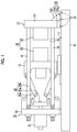
- Fig. 1 is a view illustrating a state at the time of the completion of mold opening of an injection molding machine according to an embodiment.
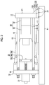
- Fig. 2 is a view illustrating a state at the time of the mold clamping of the injection molding machine according to the embodiment.
- Fig. 3 is a top view illustrating a stationary platen, a stationary mold, and a frame according to the embodiment.
- the injection molding machine has a frame Fr, a mold clamping unit 10, and the like.
- the mold clamping unit 10 performs mold closing, mold clamping, and mold opening of a mold unit 30.
- the mold clamping unit 10 has a stationary platen 12, a movable platen 13, a rear platen 15, a tie-bar 16, a toggle mechanism 20, and a mold clamping motor 21.
- a description will be made with a movement direction (rightward direction in Figs. 1 to 3 ) of the movable platen 13 at the time of mold closing as the front and a movement direction (leftward direction in Figs. 1 to 3 ) of the movable platen 13 at the time of mold opening as the rear. Additionally, a description will be made with a direction (a paper surface vertical direction in Figs. 1 and 2 and a paper surface upward-downward direction in Fig. 3 ) perpendicular to a forward-rearward direction and an upward-downward direction as a leftward-rightward direction.
- the stationary platen 12 is fixed to the frame Fr.
- a stationary mold 32 is attached to the surface of the stationary platen 12 that faces the movable platen 13.
- the movable platen 13 is made movable along a guide (for example, a guide rail) 17 laid on the frame Fr, and is made movable forward and backward with respect to the stationary platen 12.
- a movable mold 33 is attached to the surface of the movable platen 13 that faces the stationary platen 12.
- Mold closing, mold clamping, and mold opening are performed by moving the movable platen 13 forward and backward with respect to the stationary platen 12.
- the stationary mold 32 and the movable mold 33 constitute the mold unit 30.
- the rear platen 15 is coupled to the stationary platen 12 at a distance therefrom, and is placed on the frame Fr so as to be movable in a mold opening/closing direction.
- the rear platen 15 may be made movable along a guide laid on the frame Fr.
- the guide of the rear platen 15 may be shared by a guide 17 of the movable platen 13.
- the stationary platen 12 is fixed to the frame Fr and the rear platen 15 is made movable in the mold opening/closing direction with respect to the frame Fr.
- the rear platen 15 may be fixed to the frame Fr and the stationary platen 12 may be made movable in the mold opening/closing direction with respect to the frame Fr.
- the tie-bar 16 couples the stationary platen 12 and the rear platen 15 with a space therebetween.
- a plurality of the tie-bars 16 may be used.
- Each tie-bar 16 is made parallel to the mold opening/closing direction, and is extended in response to a clamping force.
- At least one tie-bar 16 may be provided with a clamping force detector 18.
- the clamping force detector 18 may be of a strain gauge type, and may detect the strain of the tie-bar 16, thereby detecting a clamping force.
- clamping force detector 18 is not limited to the strain gauge type, and may be of a piezoelectric type, a capacitance type, a hydraulic type, an electromagnetic type, or the like, and the attachment position thereof is also not limited to the tie-bars 16.
- the toggle mechanism 20 is disposed between the movable platen 13 and the rear platen 15.
- the toggle mechanism 20 is configured to include a cross-head 20a, a plurality of links 20b and 20c, and the like.
- One link 20b is rockably attached to the movable platen 13, and the other link 20c is rockably attached to the rear platen 15.
- the links 20b and 20c are bendably and stretchably coupled together by a pin or the like.
- the mold clamping motor 21 is attached to the rear platen 15, and the movable platen 13 is moved forward and backward by moving the cross-head 20a forward and backward.
- a motion conversion mechanism which converts the rotational motion of the mold clamping motor 21 into a linear motion to transmit the converted linear motion to the cross-head 20a, is provided between the mold clamping motor 21 and the cross-head 20a.
- the motion conversion mechanism is configured to include, for example, a ball screw mechanism.
- the operation of the mold clamping unit 10 is controlled by a controller.
- the controller is configured to include a microcomputer or the like, and controls a mold closing step, a mold clamping step, a mold opening step, and the like.
- the movable mold 33 is brought into contact with the stationary mold 32 by driving the mold clamping motor 21 to move the movable platen 13 forward.
- a clamping force is generating by further driving the mold clamping motor 21.
- a cavity space is formed between the movable mold 33 and the stationary mold 32 at the time of mold clamping, and the cavity space is filled with a liquid molding material.
- the molding material within the cavity space is hardened and becomes a molding product.
- the movable mold 33 is separated from the stationary mold 32 by driving the mold clamping motor 21 to move the movable platen 13 backward.
- the mold clamping unit 10 of the present embodiment has the mold clamping motor 21 as a driving source, the mold clamping unit may have a hydraulic cylinder instead of the mold clamping motor 21. Additionally, the mold clamping unit 10 may have a linear motor for mold opening and closing, and may have an electromagnet for mold clamping.
- the stationary platen 12 is fixed to the frame Fr with a bolt 22.
- a bolt hole corresponding to the bolt 22 is formed in the frame Fr.
- a plurality of the bolts 22 and a plurality of the bolt holes may be provided.
- the stationary platen 12 has a stationary platen body part 121, a connecting part 122, and a reinforcing part 123.
- the stationary mold 32 is attached to the stationary platen body part 121.
- the stationary mold 32 is attached to a rear surface of the stationary platen body part 121.
- the tie-bars 16 other than the stationary mold 32 are attached to the stationary platen body part 121.
- the connecting part 122 connects the stationary platen body part 121 and the frame Fr.
- a plurality of (for example, two) the connecting parts 122 may be provided with a space therebetween in the leftward-rightward direction.
- Each connecting part 122 supports the stationary platen body part 121 from below.
- the connecting part 122 includes a plate part 122a and a pillar part 122b.
- the plate part 122a is placed on the frame Fr.
- the pillar part 122b connects the plate part 122a and the stationary platen body part 121.
- Insertion holes through which the bolts 22 are inserted are formed in the plate part 122a.
- a plurality of the insertion holes may be formed corresponding to the plurality of bolts 22.
- the bolts 22 are threadedly engaged with the bolt holes of the frame Fr, and fixation of the stationary platen 12 to the frame Fr is performed by clamping the plate part 122a to the frame Fr with the bolts 22.
- the positions of the bolts 22 represent the positions of the stationary platen 12 fixed to the frame Fr.
- the reinforcing part 123 protrudes at least to one side (the front in Figs. 1 to 3 ) in the mold opening/closing direction from at least one (both in Figs. 1 and 2 ) of the stationary platen body part 121 and the connecting part 122, and the tilting of the stationary platen body part 121 is limited.
- the reinforcing part 123 may protrude to the front from both of a front surface (a surface opposite to the stationary mold 32) of the stationary platen body part 121 and a front surface of the pillar part 122b.
- a plurality of (for example, two) the reinforcing parts 123 may be provided at intervals in the leftward-rightward direction.
- Each reinforcing part 123 may be, for example a plate-like rib perpendicular to a front surface of the stationary platen body part 121, the front surface of the pillar part 122b, and an upper surface of the plate part 122a.
- the reinforcing part 123 protrudes to the front, using as a reference a member (hereinafter referred to as a reference member) from which the reinforcing part 123 protrudes out of the stationary platen body part 121 and the connecting part 122, and limits forward tilting of the stationary platen body part 121.
- the resistance force of the reinforcing part 123 against compression can limit the forward tilting of the stationary platen body part 121.
- the bolts 22 can limit backward tilting of the stationary platen body part 121.
- the positional relationship between the reinforcing part 123 and the bolts 22 is set so that the bolts 22 can sufficiently limit the backward tilting of the stationary platen body part 121, sufficiently using the resistance force of the reinforcing part 123 against pulling.
- At least one (two in Fig. 3 ) of the positions of the bolts 22 is disposed on the same side as the reinforcing part 123 with the reference member as a reference, and overlap a zone A1 or A2 parallel to the mold opening/closing direction passing through the reinforcing part 123 and equal to the width of the zone A1 or A2 of the reinforcing part 123 in a top view.
- the zone A1 or A2 includes a region obtained by extending the reinforcing part 123 in the mold opening/closing direction. At least some of the bolts 22 may overlap the zone A1 or A2 in the top view.
- the resistance force of the reinforcing part 123 against pulling can be sufficiently used when a reaction force caused by the action of the mold clamping unit 10 acts on the stationary platen body part 121.
- the lifting of the plate part 122a can be suppressed, and the backward tilting of the stationary platen body part 121 can be sufficiently limited.
- the center of at least one of the positions of the bolts 22 may be disposed on the same side as the reinforcing part 123 with the reference member as a reference, and may overlap a straight line L1 or L2 parallel to the mold opening/closing direction passing through the center of the reinforcing part 123 in the top view. This arrangement can further suppress the lifting of the plate part 122a.
- At least one of the positions of the bolts 22 may be disposed on the same side as the reinforcing part 123 with the reference member as a reference, and may overlap a region obtained by extending the reinforcing part 123 in the mold opening/closing direction in the top view. A bolt that overlaps this region in the top view fastens the plate part 122a to the frame Fr.
- At least one of the positions of the bolts 22 may be disposed on the same side as the reinforcing part 123 with the reference member as a reference, and may overlap the reinforcing part 123 in the top view.
- the bolts 22 that overlap the reinforcing part 123 in the top view fasten the reinforcing part 123 to the frame Fr.
- the reinforcing part 123 of the above embodiment protrudes to the front from both of the stationary platen body part 121 and the connecting part 122
- the reinforcing part may protrude to the front from any one of the stationary platen body part and the connecting part. That is, the reinforcing part 123 may protrude to the front only from the stationary platen body part 121, or may protrude to the front only from the connecting part 122.
- the reinforcing part 123 of the above embodiment protrudes to the front from the reference member
- the reinforcing part may protrude to the rear. Even in this case, as long as at least one of the positions of the bolts 22 is disposed on the same side as the reinforcing part 123 with the reference member as a reference, and is disposed on the same straight line parallel to the reinforcing part 123 in the mold opening/closing direction, the tilting of the stationary platen body part 121 can be suppressed.
- the reinforcing part 123 may protrude to both the front and the rear from the reference member.
- the reinforcing part 123 of the above embodiment is connected to the plate part 122a, the reinforcing part may be installed in the frame Fr without being connected to the plate part 122a.
- the reinforcing part 123 may be a rod-shaped member that is obliquely installed on the upper surface of the frame Fr.
- a plate separate from the plate part 122a may be provided under the rod-shaped member. This plate may be fastened to the frame Fr with the bolts 22.
- the connecting part 122 of the above embodiment supports the stationary platen body part 121 from below
- the connecting part may support the stationary platen body part 121 from the side (the left or the right).
- the connecting part may further have a horizontal part that horizontally extends from an upper end of the pillar part 122b.
- a front end of a horizontal part is connected to a central part of the stationary platen body part 121 in the upward-downward direction.
- the reinforcing part just has to protrude to the front, the rear, or both of the front and the rear from at least one of the stationary platen body part 121 and the connecting part 122.
- the stationary platen 12 is fixed to the frame Fr.
- the rear platen 15 may be fixed to the frame Fr.
- the rear platen 15 has a rear platen body part corresponding to the stationary platen body part 121, a connecting part corresponding to the connecting part 122, and a reinforcing part corresponding to the reinforcing part 123.
- the tie-bars 16 are attached to the rear platen body part.
Landscapes
- Engineering & Computer Science (AREA)
- Manufacturing & Machinery (AREA)
- Mechanical Engineering (AREA)
- Moulds For Moulding Plastics Or The Like (AREA)
Abstract
Description
- Priority is claimed to Japanese Patent Application No.
2015-073972, filed March 31, 2015 - The present invention relates to an injection molding machine.
- Injection molding machines have a mold clamping unit that performs mold opening, mold clamping, and mold closing of a mold unit, and a frame that supports the mold clamping unit (for example, refer to Japanese Unexamined Patent Application Publication No.
2002-337184 - The platen fixed to the frame may be tilted due to the operation of the mold clamping unit, and a technique of suppressing the tilting has been desired.
- The invention has been made in view of the above problems, and a main object thereof is to provide an injection molding machine that suppresses the tilting of a platen fixed to a frame.
- In order to solve the above problems, according to an aspect of the invention, there is provided an injection molding machine including a platen fixed to a frame. The platen includes a platen body part, a connecting part that connects the platen body part and the frame, and a reinforcing part that protrudes at least to one side in a mold opening/closing direction from at least one of the platen body part or the connecting part, and limits the tilting of the platen body part. At least one of the fixed positions of the platen fixed to the frame is disposed on the same side as the reinforcing part, using a member from which the reinforcing part protrudes out of the platen body part and the connecting part as a reference, and overlaps a zone parallel to the mold opening/closing direction passing through the reinforcing part and equal to the width of the reinforcing part in a top view.
- According to the aspect of the invention, provided is the injection molding machine that suppresses the tilting of the platen fixed to the frame.
-
-
Fig. 1 is a view illustrating a state at the time of the completion of mold opening of an injection molding machine according to an embodiment. -
Fig. 2 is a view illustrating a state at the time of the mold clamping of the injection molding machine according to the embodiment. -
Fig. 3 is a top view illustrating a stationary platen, a stationary mold, and a frame according to the embodiment. - Although an embodiment for carrying out the invention will be described below with reference to the drawings, the same or corresponding components will be designated by the same or corresponding reference signs, and the description thereof will be omitted.
-
Fig. 1 is a view illustrating a state at the time of the completion of mold opening of an injection molding machine according to an embodiment.Fig. 2 is a view illustrating a state at the time of the mold clamping of the injection molding machine according to the embodiment.Fig. 3 is a top view illustrating a stationary platen, a stationary mold, and a frame according to the embodiment. The injection molding machine has a frame Fr, amold clamping unit 10, and the like. - The
mold clamping unit 10 performs mold closing, mold clamping, and mold opening of amold unit 30. Themold clamping unit 10 has astationary platen 12, amovable platen 13, arear platen 15, a tie-bar 16, atoggle mechanism 20, and amold clamping motor 21. - Hereinafter, a description will be made with a movement direction (rightward direction in
Figs. 1 to 3 ) of themovable platen 13 at the time of mold closing as the front and a movement direction (leftward direction inFigs. 1 to 3 ) of themovable platen 13 at the time of mold opening as the rear. Additionally, a description will be made with a direction (a paper surface vertical direction inFigs. 1 and2 and a paper surface upward-downward direction inFig. 3 ) perpendicular to a forward-rearward direction and an upward-downward direction as a leftward-rightward direction. - The
stationary platen 12 is fixed to the frame Fr. Astationary mold 32 is attached to the surface of thestationary platen 12 that faces themovable platen 13. - The
movable platen 13 is made movable along a guide (for example, a guide rail) 17 laid on the frame Fr, and is made movable forward and backward with respect to thestationary platen 12. Amovable mold 33 is attached to the surface of themovable platen 13 that faces thestationary platen 12. - Mold closing, mold clamping, and mold opening are performed by moving the
movable platen 13 forward and backward with respect to thestationary platen 12. Thestationary mold 32 and themovable mold 33 constitute themold unit 30. - The
rear platen 15 is coupled to thestationary platen 12 at a distance therefrom, and is placed on the frame Fr so as to be movable in a mold opening/closing direction. In addition, therear platen 15 may be made movable along a guide laid on the frame Fr. The guide of therear platen 15 may be shared by aguide 17 of themovable platen 13. - In addition, in the present embodiment, the
stationary platen 12 is fixed to the frame Fr and therear platen 15 is made movable in the mold opening/closing direction with respect to the frame Fr. However, therear platen 15 may be fixed to the frame Fr and thestationary platen 12 may be made movable in the mold opening/closing direction with respect to the frame Fr. - The tie-
bar 16 couples thestationary platen 12 and therear platen 15 with a space therebetween. A plurality of the tie-bars 16 may be used. Each tie-bar 16 is made parallel to the mold opening/closing direction, and is extended in response to a clamping force. At least one tie-bar 16 may be provided with aclamping force detector 18. Theclamping force detector 18 may be of a strain gauge type, and may detect the strain of the tie-bar 16, thereby detecting a clamping force. - In addition, the
clamping force detector 18 is not limited to the strain gauge type, and may be of a piezoelectric type, a capacitance type, a hydraulic type, an electromagnetic type, or the like, and the attachment position thereof is also not limited to the tie-bars 16. - The
toggle mechanism 20 is disposed between themovable platen 13 and therear platen 15. Thetoggle mechanism 20 is configured to include across-head 20a, a plurality oflinks link 20b is rockably attached to themovable platen 13, and theother link 20c is rockably attached to therear platen 15. Thelinks cross-head 20a forward and backward, the plurality oflinks movable platen 13 is moved forward and backward with respect to therear platen 15. - The
mold clamping motor 21 is attached to therear platen 15, and themovable platen 13 is moved forward and backward by moving thecross-head 20a forward and backward. A motion conversion mechanism, which converts the rotational motion of themold clamping motor 21 into a linear motion to transmit the converted linear motion to thecross-head 20a, is provided between themold clamping motor 21 and thecross-head 20a. The motion conversion mechanism is configured to include, for example, a ball screw mechanism. - The operation of the
mold clamping unit 10 is controlled by a controller. The controller is configured to include a microcomputer or the like, and controls a mold closing step, a mold clamping step, a mold opening step, and the like. - In the mold closing step, the
movable mold 33 is brought into contact with thestationary mold 32 by driving themold clamping motor 21 to move themovable platen 13 forward. - In the mold clamping step, a clamping force is generating by further driving the
mold clamping motor 21. A cavity space is formed between themovable mold 33 and thestationary mold 32 at the time of mold clamping, and the cavity space is filled with a liquid molding material. The molding material within the cavity space is hardened and becomes a molding product. - In the mold opening step, the
movable mold 33 is separated from thestationary mold 32 by driving themold clamping motor 21 to move themovable platen 13 backward. - Although the
mold clamping unit 10 of the present embodiment has themold clamping motor 21 as a driving source, the mold clamping unit may have a hydraulic cylinder instead of themold clamping motor 21. Additionally, themold clamping unit 10 may have a linear motor for mold opening and closing, and may have an electromagnet for mold clamping. - Next, the
stationary platen 12 will be described again with reference toFigs. 1 to 3 . Thestationary platen 12 is fixed to the frame Fr with abolt 22. A bolt hole corresponding to thebolt 22 is formed in the frame Fr. A plurality of thebolts 22 and a plurality of the bolt holes may be provided. - In addition, although a method of fixing the
stationary platen 12 to the frame Fr is bolting in the present embodiment, pinning, welding, or the like may be used. - The
stationary platen 12 has a stationaryplaten body part 121, a connectingpart 122, and a reinforcingpart 123. - The
stationary mold 32 is attached to the stationaryplaten body part 121. Thestationary mold 32 is attached to a rear surface of the stationaryplaten body part 121. The tie-bars 16 other than thestationary mold 32 are attached to the stationaryplaten body part 121. - The connecting
part 122 connects the stationaryplaten body part 121 and the frame Fr. A plurality of (for example, two) the connectingparts 122 may be provided with a space therebetween in the leftward-rightward direction. Each connectingpart 122 supports the stationaryplaten body part 121 from below. - The connecting
part 122 includes aplate part 122a and apillar part 122b. Theplate part 122a is placed on the frame Fr. Thepillar part 122b connects theplate part 122a and the stationaryplaten body part 121. - Insertion holes through which the
bolts 22 are inserted are formed in theplate part 122a. A plurality of the insertion holes may be formed corresponding to the plurality ofbolts 22. Thebolts 22 are threadedly engaged with the bolt holes of the frame Fr, and fixation of thestationary platen 12 to the frame Fr is performed by clamping theplate part 122a to the frame Fr with thebolts 22. The positions of thebolts 22 represent the positions of thestationary platen 12 fixed to the frame Fr. - The reinforcing
part 123 protrudes at least to one side (the front inFigs. 1 to 3 ) in the mold opening/closing direction from at least one (both inFigs. 1 and2 ) of the stationaryplaten body part 121 and the connectingpart 122, and the tilting of the stationaryplaten body part 121 is limited. The reinforcingpart 123 may protrude to the front from both of a front surface (a surface opposite to the stationary mold 32) of the stationaryplaten body part 121 and a front surface of thepillar part 122b. A plurality of (for example, two) the reinforcingparts 123 may be provided at intervals in the leftward-rightward direction. Each reinforcingpart 123 may be, for example a plate-like rib perpendicular to a front surface of the stationaryplaten body part 121, the front surface of thepillar part 122b, and an upper surface of theplate part 122a. - Meanwhile, the reinforcing
part 123, as described above, protrudes to the front, using as a reference a member (hereinafter referred to as a reference member) from which the reinforcingpart 123 protrudes out of the stationaryplaten body part 121 and the connectingpart 122, and limits forward tilting of the stationaryplaten body part 121. The resistance force of the reinforcingpart 123 against compression can limit the forward tilting of the stationaryplaten body part 121. - Meanwhile, the
bolts 22 can limit backward tilting of the stationaryplaten body part 121. The positional relationship between the reinforcingpart 123 and thebolts 22 is set so that thebolts 22 can sufficiently limit the backward tilting of the stationaryplaten body part 121, sufficiently using the resistance force of the reinforcingpart 123 against pulling. - In the present embodiment, at least one (two in
Fig. 3 ) of the positions of thebolts 22 is disposed on the same side as the reinforcingpart 123 with the reference member as a reference, and overlap a zone A1 or A2 parallel to the mold opening/closing direction passing through the reinforcingpart 123 and equal to the width of the zone A1 or A2 of the reinforcingpart 123 in a top view. The zone A1 or A2 includes a region obtained by extending the reinforcingpart 123 in the mold opening/closing direction. At least some of thebolts 22 may overlap the zone A1 or A2 in the top view. - Since the position of at least one
bolt 22 overlaps the zone A1 or A2 in the top view, compared to a case where the positions of all thebolts 22 are outside of the zone A1 or A2, the resistance force of the reinforcingpart 123 against pulling can be sufficiently used when a reaction force caused by the action of themold clamping unit 10 acts on the stationaryplaten body part 121. Hence, the lifting of theplate part 122a can be suppressed, and the backward tilting of the stationaryplaten body part 121 can be sufficiently limited. - The center of at least one of the positions of the
bolts 22 may be disposed on the same side as the reinforcingpart 123 with the reference member as a reference, and may overlap a straight line L1 or L2 parallel to the mold opening/closing direction passing through the center of the reinforcingpart 123 in the top view. This arrangement can further suppress the lifting of theplate part 122a. - At least one of the positions of the
bolts 22 may be disposed on the same side as the reinforcingpart 123 with the reference member as a reference, and may overlap a region obtained by extending the reinforcingpart 123 in the mold opening/closing direction in the top view. A bolt that overlaps this region in the top view fastens theplate part 122a to the frame Fr. - In addition, at least one of the positions of the
bolts 22 may be disposed on the same side as the reinforcingpart 123 with the reference member as a reference, and may overlap the reinforcingpart 123 in the top view. Thebolts 22 that overlap the reinforcingpart 123 in the top view fasten the reinforcingpart 123 to the frame Fr. - Although the embodiment of the injection molding machine has been described above, the invention is not limited to the above-described embodiment, and various alterations and improvements can be made within the scope of the invention described in the claims.
- For example, although the reinforcing
part 123 of the above embodiment protrudes to the front from both of the stationaryplaten body part 121 and the connectingpart 122, the reinforcing part may protrude to the front from any one of the stationary platen body part and the connecting part. That is, the reinforcingpart 123 may protrude to the front only from the stationaryplaten body part 121, or may protrude to the front only from the connectingpart 122. - Additionally, although the reinforcing
part 123 of the above embodiment protrudes to the front from the reference member, the reinforcing part may protrude to the rear. Even in this case, as long as at least one of the positions of thebolts 22 is disposed on the same side as the reinforcingpart 123 with the reference member as a reference, and is disposed on the same straight line parallel to the reinforcingpart 123 in the mold opening/closing direction, the tilting of the stationaryplaten body part 121 can be suppressed. The reinforcingpart 123 may protrude to both the front and the rear from the reference member. - Additionally, although the reinforcing
part 123 of the above embodiment is connected to theplate part 122a, the reinforcing part may be installed in the frame Fr without being connected to theplate part 122a. For example, the reinforcingpart 123 may be a rod-shaped member that is obliquely installed on the upper surface of the frame Fr. A plate separate from theplate part 122a may be provided under the rod-shaped member. This plate may be fastened to the frame Fr with thebolts 22. - Although the connecting
part 122 of the above embodiment supports the stationaryplaten body part 121 from below, the connecting part may support the stationaryplaten body part 121 from the side (the left or the right). In this case, the connecting part may further have a horizontal part that horizontally extends from an upper end of thepillar part 122b. A front end of a horizontal part is connected to a central part of the stationaryplaten body part 121 in the upward-downward direction. Even in this case, the reinforcing part just has to protrude to the front, the rear, or both of the front and the rear from at least one of the stationaryplaten body part 121 and the connectingpart 122. - In the above embodiment, the
stationary platen 12 is fixed to the frame Fr. However, therear platen 15 may be fixed to the frame Fr. In this case, therear platen 15 has a rear platen body part corresponding to the stationaryplaten body part 121, a connecting part corresponding to the connectingpart 122, and a reinforcing part corresponding to the reinforcingpart 123. The tie-bars 16 are attached to the rear platen body part. By suppressing the tilting of therear platen 15, the tilting of thestationary platen 12 coupled to therear platen 15 via the tie-bars 16 can be suppressed.
Claims (5)
- An injection molding machine comprising:a platen fixed to a frame,wherein the platen includesa platen body part,a connecting part that connects the platen body part and the frame, anda reinforcing part that protrudes at least to one side in a mold opening/closing direction from at least one of the platen body part or the connecting part, and limits the tilting of the platen body part, andwherein at least one of the fixed positions of the platen fixed to the frame is disposed on the same side as the reinforcing part, using a member from which the reinforcing part protrudes out of the platen body part and the connecting part as a reference, and overlaps a zone parallel to the mold opening/closing direction passing through the reinforcing part and equal to the width of the reinforcing part in a top view.
- The injection molding machine according to Claim 1,
wherein the center of at least one of the fixed positions is disposed on the same side as the reinforcing part with the reference member as a reference, and overlaps a straight line parallel to the mold opening/closing direction passing through the reinforcing part in a top view. - The injection molding machine according to Claim 1 or 2,
wherein at least one of the fixed positions is disposed on the same side as the reinforcing part with the reference member as a reference, and overlaps the reinforcing part in a top view. - The injection molding machine according to any one of Claims 1 to 3,
wherein the platen is a stationary platen to which a stationary mold is attached, and
wherein the platen body part has the stationary mold attached thereto. - The injection molding machine according to any one of Claims 1 to 4,
wherein the platen is a rear platen coupled to a stationary platen, to which a stationary mold is attached, at a distance therefrom via a tie-bar, and
wherein the platen body part has the tie-bar attached thereto.
Applications Claiming Priority (1)
| Application Number | Priority Date | Filing Date | Title |
|---|---|---|---|
| JP2015073972A JP6466228B2 (en) | 2015-03-31 | 2015-03-31 | Injection molding machine |
Publications (2)
| Publication Number | Publication Date |
|---|---|
| EP3075513A1 true EP3075513A1 (en) | 2016-10-05 |
| EP3075513B1 EP3075513B1 (en) | 2018-03-07 |
Family
ID=55586225
Family Applications (1)
| Application Number | Title | Priority Date | Filing Date |
|---|---|---|---|
| EP16161128.0A Active EP3075513B1 (en) | 2015-03-31 | 2016-03-18 | Injection molding machine |
Country Status (3)
| Country | Link |
|---|---|
| EP (1) | EP3075513B1 (en) |
| JP (1) | JP6466228B2 (en) |
| CN (1) | CN106003615B (en) |
Citations (5)
| Publication number | Priority date | Publication date | Assignee | Title |
|---|---|---|---|---|
| DE8401999U1 (en) * | 1984-01-25 | 1986-02-13 | Hehl, Karl, 7298 Loßburg | Plastic injection molding machine with a mold clamping unit supported by its stationary mold carrier and an abutment plate |
| JP2002337184A (en) | 2001-05-16 | 2002-11-27 | Sumitomo Heavy Ind Ltd | Drive source support device for injection molding machine |
| JP2003025378A (en) * | 2001-07-13 | 2003-01-29 | Sumitomo Heavy Ind Ltd | Fixed mold support device for injection molding machine |
| EP1837153A1 (en) * | 2006-03-24 | 2007-09-26 | Fanuc Ltd | Mold clamping mechanism of injection molding machine |
| US20080175944A1 (en) * | 2007-01-24 | 2008-07-24 | Husky Injection Molding Systems Ltd. | Molding-System Platen having Anti-Tilt Structure |
Family Cites Families (4)
| Publication number | Priority date | Publication date | Assignee | Title |
|---|---|---|---|---|
| JP3098511B1 (en) * | 1999-04-13 | 2000-10-16 | ファナック株式会社 | Mold clamping mechanism of injection molding machine |
| US7670536B2 (en) * | 2007-02-05 | 2010-03-02 | Husky Injection Moding Systems Ltd. | Molding-system clamp |
| JP4270327B1 (en) * | 2008-07-09 | 2009-05-27 | 株式会社ニイガタマシンテクノ | Molding device for injection molding machine |
| JP4750195B2 (en) * | 2009-04-09 | 2011-08-17 | ファナック株式会社 | Injection molding machine with nozzle touch mechanism |
-
2015
- 2015-03-31 JP JP2015073972A patent/JP6466228B2/en active Active
-
2016
- 2016-03-01 CN CN201610115057.5A patent/CN106003615B/en active Active
- 2016-03-18 EP EP16161128.0A patent/EP3075513B1/en active Active
Patent Citations (5)
| Publication number | Priority date | Publication date | Assignee | Title |
|---|---|---|---|---|
| DE8401999U1 (en) * | 1984-01-25 | 1986-02-13 | Hehl, Karl, 7298 Loßburg | Plastic injection molding machine with a mold clamping unit supported by its stationary mold carrier and an abutment plate |
| JP2002337184A (en) | 2001-05-16 | 2002-11-27 | Sumitomo Heavy Ind Ltd | Drive source support device for injection molding machine |
| JP2003025378A (en) * | 2001-07-13 | 2003-01-29 | Sumitomo Heavy Ind Ltd | Fixed mold support device for injection molding machine |
| EP1837153A1 (en) * | 2006-03-24 | 2007-09-26 | Fanuc Ltd | Mold clamping mechanism of injection molding machine |
| US20080175944A1 (en) * | 2007-01-24 | 2008-07-24 | Husky Injection Molding Systems Ltd. | Molding-System Platen having Anti-Tilt Structure |
Also Published As
| Publication number | Publication date |
|---|---|
| CN106003615B (en) | 2019-02-22 |
| JP6466228B2 (en) | 2019-02-06 |
| CN106003615A (en) | 2016-10-12 |
| JP2016193518A (en) | 2016-11-17 |
| EP3075513B1 (en) | 2018-03-07 |
Similar Documents
| Publication | Publication Date | Title |
|---|---|---|
| JP6184908B2 (en) | Opening and closing device and molding device | |
| CN103958153B (en) | Nozzle touches mechanism and injection machine | |
| US20250010532A1 (en) | Injection device, injection molding machine, and nozzle touch method | |
| EP3210744A1 (en) | Injection molding machine | |
| JP4288627B1 (en) | Molding device for injection molding machine | |
| KR101555129B1 (en) | Injection molding machine | |
| EP2977167B1 (en) | Injection molding machine | |
| EP3075513B1 (en) | Injection molding machine | |
| KR20190048727A (en) | Control device for forging press | |
| JP6012893B1 (en) | Resin molding equipment | |
| JP2015071278A (en) | Mold clamping device of injection molding machine having a platen adjustment mechanism | |
| KR101739190B1 (en) | Injection molding machine | |
| CN109895321B (en) | Machine table of injection molding machine | |
| EP3147097B1 (en) | Injection molding machine | |
| CN104943101B (en) | Closing unit and forming machine | |
| EP2993024B1 (en) | Injection molding machine | |
| EP3434438A1 (en) | Injection molding machine | |
| KR102174128B1 (en) | Injection molding machine | |
| KR101618973B1 (en) | Injection molding machine | |
| JP5681235B2 (en) | Molding device for injection molding machine | |
| CN105835323A (en) | Injection molding machine | |
| WO2016031812A1 (en) | Movable-platen support device, movable platen, mold opening/closing device, and molding device | |
| EP3075514B1 (en) | Injection molding machine | |
| EP3075515B1 (en) | Injection molding machine | |
| JP2007210294A (en) | Molding machine |
Legal Events
| Date | Code | Title | Description |
|---|---|---|---|
| PUAI | Public reference made under article 153(3) epc to a published international application that has entered the european phase |
Free format text: ORIGINAL CODE: 0009012 |
|
| 17P | Request for examination filed |
Effective date: 20160318 |
|
| AK | Designated contracting states |
Kind code of ref document: A1 Designated state(s): AL AT BE BG CH CY CZ DE DK EE ES FI FR GB GR HR HU IE IS IT LI LT LU LV MC MK MT NL NO PL PT RO RS SE SI SK SM TR |
|
| AX | Request for extension of the european patent |
Extension state: BA ME |
|
| GRAP | Despatch of communication of intention to grant a patent |
Free format text: ORIGINAL CODE: EPIDOSNIGR1 |
|
| INTG | Intention to grant announced |
Effective date: 20170914 |
|
| GRAS | Grant fee paid |
Free format text: ORIGINAL CODE: EPIDOSNIGR3 |
|
| GRAA | (expected) grant |
Free format text: ORIGINAL CODE: 0009210 |
|
| AK | Designated contracting states |
Kind code of ref document: B1 Designated state(s): AL AT BE BG CH CY CZ DE DK EE ES FI FR GB GR HR HU IE IS IT LI LT LU LV MC MK MT NL NO PL PT RO RS SE SI SK SM TR |
|
| REG | Reference to a national code |
Ref country code: GB Ref legal event code: FG4D |
|
| REG | Reference to a national code |
Ref country code: CH Ref legal event code: EP Ref country code: AT Ref legal event code: REF Ref document number: 976067 Country of ref document: AT Kind code of ref document: T Effective date: 20180315 |
|
| REG | Reference to a national code |
Ref country code: DE Ref legal event code: R096 Ref document number: 602016001771 Country of ref document: DE |
|
| REG | Reference to a national code |
Ref country code: IE Ref legal event code: FG4D |
|
| REG | Reference to a national code |
Ref country code: CH Ref legal event code: NV Representative=s name: SCHNEIDER FELDMANN AG PATENT- UND MARKENANWAEL, CH |
|
| REG | Reference to a national code |
Ref country code: NL Ref legal event code: MP Effective date: 20180307 |
|
| REG | Reference to a national code |
Ref country code: LT Ref legal event code: MG4D |
|
| PG25 | Lapsed in a contracting state [announced via postgrant information from national office to epo] |
Ref country code: HR Free format text: LAPSE BECAUSE OF FAILURE TO SUBMIT A TRANSLATION OF THE DESCRIPTION OR TO PAY THE FEE WITHIN THE PRESCRIBED TIME-LIMIT Effective date: 20180307 Ref country code: CY Free format text: LAPSE BECAUSE OF FAILURE TO SUBMIT A TRANSLATION OF THE DESCRIPTION OR TO PAY THE FEE WITHIN THE PRESCRIBED TIME-LIMIT Effective date: 20180307 Ref country code: LT Free format text: LAPSE BECAUSE OF FAILURE TO SUBMIT A TRANSLATION OF THE DESCRIPTION OR TO PAY THE FEE WITHIN THE PRESCRIBED TIME-LIMIT Effective date: 20180307 Ref country code: NO Free format text: LAPSE BECAUSE OF FAILURE TO SUBMIT A TRANSLATION OF THE DESCRIPTION OR TO PAY THE FEE WITHIN THE PRESCRIBED TIME-LIMIT Effective date: 20180607 Ref country code: FI Free format text: LAPSE BECAUSE OF FAILURE TO SUBMIT A TRANSLATION OF THE DESCRIPTION OR TO PAY THE FEE WITHIN THE PRESCRIBED TIME-LIMIT Effective date: 20180307 Ref country code: ES Free format text: LAPSE BECAUSE OF FAILURE TO SUBMIT A TRANSLATION OF THE DESCRIPTION OR TO PAY THE FEE WITHIN THE PRESCRIBED TIME-LIMIT Effective date: 20180307 |
|
| PG25 | Lapsed in a contracting state [announced via postgrant information from national office to epo] |
Ref country code: RS Free format text: LAPSE BECAUSE OF FAILURE TO SUBMIT A TRANSLATION OF THE DESCRIPTION OR TO PAY THE FEE WITHIN THE PRESCRIBED TIME-LIMIT Effective date: 20180307 Ref country code: GR Free format text: LAPSE BECAUSE OF FAILURE TO SUBMIT A TRANSLATION OF THE DESCRIPTION OR TO PAY THE FEE WITHIN THE PRESCRIBED TIME-LIMIT Effective date: 20180608 Ref country code: LV Free format text: LAPSE BECAUSE OF FAILURE TO SUBMIT A TRANSLATION OF THE DESCRIPTION OR TO PAY THE FEE WITHIN THE PRESCRIBED TIME-LIMIT Effective date: 20180307 Ref country code: SE Free format text: LAPSE BECAUSE OF FAILURE TO SUBMIT A TRANSLATION OF THE DESCRIPTION OR TO PAY THE FEE WITHIN THE PRESCRIBED TIME-LIMIT Effective date: 20180307 Ref country code: BG Free format text: LAPSE BECAUSE OF FAILURE TO SUBMIT A TRANSLATION OF THE DESCRIPTION OR TO PAY THE FEE WITHIN THE PRESCRIBED TIME-LIMIT Effective date: 20180607 |
|
| PG25 | Lapsed in a contracting state [announced via postgrant information from national office to epo] |
Ref country code: AL Free format text: LAPSE BECAUSE OF FAILURE TO SUBMIT A TRANSLATION OF THE DESCRIPTION OR TO PAY THE FEE WITHIN THE PRESCRIBED TIME-LIMIT Effective date: 20180307 Ref country code: EE Free format text: LAPSE BECAUSE OF FAILURE TO SUBMIT A TRANSLATION OF THE DESCRIPTION OR TO PAY THE FEE WITHIN THE PRESCRIBED TIME-LIMIT Effective date: 20180307 Ref country code: IT Free format text: LAPSE BECAUSE OF FAILURE TO SUBMIT A TRANSLATION OF THE DESCRIPTION OR TO PAY THE FEE WITHIN THE PRESCRIBED TIME-LIMIT Effective date: 20180307 Ref country code: RO Free format text: LAPSE BECAUSE OF FAILURE TO SUBMIT A TRANSLATION OF THE DESCRIPTION OR TO PAY THE FEE WITHIN THE PRESCRIBED TIME-LIMIT Effective date: 20180307 Ref country code: NL Free format text: LAPSE BECAUSE OF FAILURE TO SUBMIT A TRANSLATION OF THE DESCRIPTION OR TO PAY THE FEE WITHIN THE PRESCRIBED TIME-LIMIT Effective date: 20180307 Ref country code: PL Free format text: LAPSE BECAUSE OF FAILURE TO SUBMIT A TRANSLATION OF THE DESCRIPTION OR TO PAY THE FEE WITHIN THE PRESCRIBED TIME-LIMIT Effective date: 20180307 |
|
| PG25 | Lapsed in a contracting state [announced via postgrant information from national office to epo] |
Ref country code: SK Free format text: LAPSE BECAUSE OF FAILURE TO SUBMIT A TRANSLATION OF THE DESCRIPTION OR TO PAY THE FEE WITHIN THE PRESCRIBED TIME-LIMIT Effective date: 20180307 Ref country code: CZ Free format text: LAPSE BECAUSE OF FAILURE TO SUBMIT A TRANSLATION OF THE DESCRIPTION OR TO PAY THE FEE WITHIN THE PRESCRIBED TIME-LIMIT Effective date: 20180307 Ref country code: SM Free format text: LAPSE BECAUSE OF FAILURE TO SUBMIT A TRANSLATION OF THE DESCRIPTION OR TO PAY THE FEE WITHIN THE PRESCRIBED TIME-LIMIT Effective date: 20180307 |
|
| REG | Reference to a national code |
Ref country code: BE Ref legal event code: MM Effective date: 20180331 Ref country code: DE Ref legal event code: R097 Ref document number: 602016001771 Country of ref document: DE |
|
| REG | Reference to a national code |
Ref country code: IE Ref legal event code: MM4A |
|
| PG25 | Lapsed in a contracting state [announced via postgrant information from national office to epo] |
Ref country code: PT Free format text: LAPSE BECAUSE OF FAILURE TO SUBMIT A TRANSLATION OF THE DESCRIPTION OR TO PAY THE FEE WITHIN THE PRESCRIBED TIME-LIMIT Effective date: 20180709 Ref country code: LU Free format text: LAPSE BECAUSE OF NON-PAYMENT OF DUE FEES Effective date: 20180318 |
|
| PLBE | No opposition filed within time limit |
Free format text: ORIGINAL CODE: 0009261 |
|
| STAA | Information on the status of an ep patent application or granted ep patent |
Free format text: STATUS: NO OPPOSITION FILED WITHIN TIME LIMIT |
|
| PG25 | Lapsed in a contracting state [announced via postgrant information from national office to epo] |
Ref country code: IE Free format text: LAPSE BECAUSE OF NON-PAYMENT OF DUE FEES Effective date: 20180318 Ref country code: DK Free format text: LAPSE BECAUSE OF FAILURE TO SUBMIT A TRANSLATION OF THE DESCRIPTION OR TO PAY THE FEE WITHIN THE PRESCRIBED TIME-LIMIT Effective date: 20180307 Ref country code: MC Free format text: LAPSE BECAUSE OF FAILURE TO SUBMIT A TRANSLATION OF THE DESCRIPTION OR TO PAY THE FEE WITHIN THE PRESCRIBED TIME-LIMIT Effective date: 20180307 |
|
| 26N | No opposition filed |
Effective date: 20181210 |
|
| PG25 | Lapsed in a contracting state [announced via postgrant information from national office to epo] |
Ref country code: SI Free format text: LAPSE BECAUSE OF FAILURE TO SUBMIT A TRANSLATION OF THE DESCRIPTION OR TO PAY THE FEE WITHIN THE PRESCRIBED TIME-LIMIT Effective date: 20180307 Ref country code: BE Free format text: LAPSE BECAUSE OF NON-PAYMENT OF DUE FEES Effective date: 20180331 |
|
| PG25 | Lapsed in a contracting state [announced via postgrant information from national office to epo] |
Ref country code: FR Free format text: LAPSE BECAUSE OF NON-PAYMENT OF DUE FEES Effective date: 20180507 |
|
| PG25 | Lapsed in a contracting state [announced via postgrant information from national office to epo] |
Ref country code: MT Free format text: LAPSE BECAUSE OF NON-PAYMENT OF DUE FEES Effective date: 20180318 |
|
| PG25 | Lapsed in a contracting state [announced via postgrant information from national office to epo] |
Ref country code: TR Free format text: LAPSE BECAUSE OF FAILURE TO SUBMIT A TRANSLATION OF THE DESCRIPTION OR TO PAY THE FEE WITHIN THE PRESCRIBED TIME-LIMIT Effective date: 20180307 |
|
| PG25 | Lapsed in a contracting state [announced via postgrant information from national office to epo] |
Ref country code: MK Free format text: LAPSE BECAUSE OF NON-PAYMENT OF DUE FEES Effective date: 20180307 Ref country code: HU Free format text: LAPSE BECAUSE OF FAILURE TO SUBMIT A TRANSLATION OF THE DESCRIPTION OR TO PAY THE FEE WITHIN THE PRESCRIBED TIME-LIMIT; INVALID AB INITIO Effective date: 20160318 |
|
| REG | Reference to a national code |
Ref country code: AT Ref legal event code: UEP Ref document number: 976067 Country of ref document: AT Kind code of ref document: T Effective date: 20180307 |
|
| PG25 | Lapsed in a contracting state [announced via postgrant information from national office to epo] |
Ref country code: IS Free format text: LAPSE BECAUSE OF FAILURE TO SUBMIT A TRANSLATION OF THE DESCRIPTION OR TO PAY THE FEE WITHIN THE PRESCRIBED TIME-LIMIT Effective date: 20180707 |
|
| REG | Reference to a national code |
Ref country code: CH Ref legal event code: PFA Owner name: SUMITOMO HEAVY INDUSTRIES, LTD., JP Free format text: FORMER OWNER: SUMITOMO HEAVY INDUSTRIES, LTD., JP |
|
| GBPC | Gb: european patent ceased through non-payment of renewal fee |
Effective date: 20200318 |
|
| PG25 | Lapsed in a contracting state [announced via postgrant information from national office to epo] |
Ref country code: GB Free format text: LAPSE BECAUSE OF NON-PAYMENT OF DUE FEES Effective date: 20200318 |
|
| PGFP | Annual fee paid to national office [announced via postgrant information from national office to epo] |
Ref country code: CH Payment date: 20220215 Year of fee payment: 7 Ref country code: AT Payment date: 20220225 Year of fee payment: 7 |
|
| REG | Reference to a national code |
Ref country code: CH Ref legal event code: PL |
|
| REG | Reference to a national code |
Ref country code: AT Ref legal event code: MM01 Ref document number: 976067 Country of ref document: AT Kind code of ref document: T Effective date: 20230318 |
|
| PG25 | Lapsed in a contracting state [announced via postgrant information from national office to epo] |
Ref country code: LI Free format text: LAPSE BECAUSE OF NON-PAYMENT OF DUE FEES Effective date: 20230331 Ref country code: CH Free format text: LAPSE BECAUSE OF NON-PAYMENT OF DUE FEES Effective date: 20230331 Ref country code: AT Free format text: LAPSE BECAUSE OF NON-PAYMENT OF DUE FEES Effective date: 20230318 |
|
| PGFP | Annual fee paid to national office [announced via postgrant information from national office to epo] |
Ref country code: DE Payment date: 20260128 Year of fee payment: 11 |