EP3075508A2 - Eyeglass lens processing apparatus, eyeglass lens processing control data acquisition apparatus and eyeglass lens processing method - Google Patents
Eyeglass lens processing apparatus, eyeglass lens processing control data acquisition apparatus and eyeglass lens processing method Download PDFInfo
- Publication number
- EP3075508A2 EP3075508A2 EP16163193.2A EP16163193A EP3075508A2 EP 3075508 A2 EP3075508 A2 EP 3075508A2 EP 16163193 A EP16163193 A EP 16163193A EP 3075508 A2 EP3075508 A2 EP 3075508A2
- Authority
- EP
- European Patent Office
- Prior art keywords
- boring
- shaft
- drive shaft
- rotation
- processing tool
- Prior art date
- Legal status (The legal status is an assumption and is not a legal conclusion. Google has not performed a legal analysis and makes no representation as to the accuracy of the status listed.)
- Granted
Links
Images




Classifications
-
- B—PERFORMING OPERATIONS; TRANSPORTING
- B24—GRINDING; POLISHING
- B24B—MACHINES, DEVICES, OR PROCESSES FOR GRINDING OR POLISHING; DRESSING OR CONDITIONING OF ABRADING SURFACES; FEEDING OF GRINDING, POLISHING, OR LAPPING AGENTS
- B24B9/00—Machines or devices designed for grinding edges or bevels on work or for removing burrs; Accessories therefor
- B24B9/02—Machines or devices designed for grinding edges or bevels on work or for removing burrs; Accessories therefor characterised by a special design with respect to properties of materials specific to articles to be ground
- B24B9/06—Machines or devices designed for grinding edges or bevels on work or for removing burrs; Accessories therefor characterised by a special design with respect to properties of materials specific to articles to be ground of non-metallic inorganic material, e.g. stone, ceramics, porcelain
- B24B9/08—Machines or devices designed for grinding edges or bevels on work or for removing burrs; Accessories therefor characterised by a special design with respect to properties of materials specific to articles to be ground of non-metallic inorganic material, e.g. stone, ceramics, porcelain of glass
- B24B9/14—Machines or devices designed for grinding edges or bevels on work or for removing burrs; Accessories therefor characterised by a special design with respect to properties of materials specific to articles to be ground of non-metallic inorganic material, e.g. stone, ceramics, porcelain of glass of optical work, e.g. lenses, prisms
-
- B—PERFORMING OPERATIONS; TRANSPORTING
- B24—GRINDING; POLISHING
- B24B—MACHINES, DEVICES, OR PROCESSES FOR GRINDING OR POLISHING; DRESSING OR CONDITIONING OF ABRADING SURFACES; FEEDING OF GRINDING, POLISHING, OR LAPPING AGENTS
- B24B19/00—Single-purpose machines or devices for particular grinding operations not covered by any other main group
- B24B19/02—Single-purpose machines or devices for particular grinding operations not covered by any other main group for grinding grooves, e.g. on shafts, in casings, in tubes, homokinetic joint elements
-
- B—PERFORMING OPERATIONS; TRANSPORTING
- B24—GRINDING; POLISHING
- B24B—MACHINES, DEVICES, OR PROCESSES FOR GRINDING OR POLISHING; DRESSING OR CONDITIONING OF ABRADING SURFACES; FEEDING OF GRINDING, POLISHING, OR LAPPING AGENTS
- B24B27/00—Other grinding machines or devices
- B24B27/0076—Other grinding machines or devices grinding machines comprising two or more grinding tools
-
- B—PERFORMING OPERATIONS; TRANSPORTING
- B24—GRINDING; POLISHING
- B24B—MACHINES, DEVICES, OR PROCESSES FOR GRINDING OR POLISHING; DRESSING OR CONDITIONING OF ABRADING SURFACES; FEEDING OF GRINDING, POLISHING, OR LAPPING AGENTS
- B24B41/00—Component parts such as frames, beds, carriages, headstocks
- B24B41/06—Work supports, e.g. adjustable steadies
- B24B41/061—Work supports, e.g. adjustable steadies axially supporting turning workpieces, e.g. magnetically, pneumatically
-
- B—PERFORMING OPERATIONS; TRANSPORTING
- B24—GRINDING; POLISHING
- B24B—MACHINES, DEVICES, OR PROCESSES FOR GRINDING OR POLISHING; DRESSING OR CONDITIONING OF ABRADING SURFACES; FEEDING OF GRINDING, POLISHING, OR LAPPING AGENTS
- B24B47/00—Drives or gearings; Equipment therefor
- B24B47/10—Drives or gearings; Equipment therefor for rotating or reciprocating working-spindles carrying grinding wheels or workpieces
- B24B47/12—Drives or gearings; Equipment therefor for rotating or reciprocating working-spindles carrying grinding wheels or workpieces by mechanical gearing or electric power
-
- B—PERFORMING OPERATIONS; TRANSPORTING
- B24—GRINDING; POLISHING
- B24B—MACHINES, DEVICES, OR PROCESSES FOR GRINDING OR POLISHING; DRESSING OR CONDITIONING OF ABRADING SURFACES; FEEDING OF GRINDING, POLISHING, OR LAPPING AGENTS
- B24B49/00—Measuring or gauging equipment for controlling the feed movement of the grinding tool or work; Arrangements of indicating or measuring equipment, e.g. for indicating the start of the grinding operation
- B24B49/12—Measuring or gauging equipment for controlling the feed movement of the grinding tool or work; Arrangements of indicating or measuring equipment, e.g. for indicating the start of the grinding operation involving optical means
-
- B—PERFORMING OPERATIONS; TRANSPORTING
- B24—GRINDING; POLISHING
- B24B—MACHINES, DEVICES, OR PROCESSES FOR GRINDING OR POLISHING; DRESSING OR CONDITIONING OF ABRADING SURFACES; FEEDING OF GRINDING, POLISHING, OR LAPPING AGENTS
- B24B9/00—Machines or devices designed for grinding edges or bevels on work or for removing burrs; Accessories therefor
- B24B9/02—Machines or devices designed for grinding edges or bevels on work or for removing burrs; Accessories therefor characterised by a special design with respect to properties of materials specific to articles to be ground
- B24B9/06—Machines or devices designed for grinding edges or bevels on work or for removing burrs; Accessories therefor characterised by a special design with respect to properties of materials specific to articles to be ground of non-metallic inorganic material, e.g. stone, ceramics, porcelain
- B24B9/08—Machines or devices designed for grinding edges or bevels on work or for removing burrs; Accessories therefor characterised by a special design with respect to properties of materials specific to articles to be ground of non-metallic inorganic material, e.g. stone, ceramics, porcelain of glass
- B24B9/14—Machines or devices designed for grinding edges or bevels on work or for removing burrs; Accessories therefor characterised by a special design with respect to properties of materials specific to articles to be ground of non-metallic inorganic material, e.g. stone, ceramics, porcelain of glass of optical work, e.g. lenses, prisms
- B24B9/146—Accessories, e.g. lens mounting devices
-
- B—PERFORMING OPERATIONS; TRANSPORTING
- B24—GRINDING; POLISHING
- B24B—MACHINES, DEVICES, OR PROCESSES FOR GRINDING OR POLISHING; DRESSING OR CONDITIONING OF ABRADING SURFACES; FEEDING OF GRINDING, POLISHING, OR LAPPING AGENTS
- B24B9/00—Machines or devices designed for grinding edges or bevels on work or for removing burrs; Accessories therefor
- B24B9/02—Machines or devices designed for grinding edges or bevels on work or for removing burrs; Accessories therefor characterised by a special design with respect to properties of materials specific to articles to be ground
- B24B9/06—Machines or devices designed for grinding edges or bevels on work or for removing burrs; Accessories therefor characterised by a special design with respect to properties of materials specific to articles to be ground of non-metallic inorganic material, e.g. stone, ceramics, porcelain
- B24B9/08—Machines or devices designed for grinding edges or bevels on work or for removing burrs; Accessories therefor characterised by a special design with respect to properties of materials specific to articles to be ground of non-metallic inorganic material, e.g. stone, ceramics, porcelain of glass
- B24B9/14—Machines or devices designed for grinding edges or bevels on work or for removing burrs; Accessories therefor characterised by a special design with respect to properties of materials specific to articles to be ground of non-metallic inorganic material, e.g. stone, ceramics, porcelain of glass of optical work, e.g. lenses, prisms
- B24B9/148—Machines or devices designed for grinding edges or bevels on work or for removing burrs; Accessories therefor characterised by a special design with respect to properties of materials specific to articles to be ground of non-metallic inorganic material, e.g. stone, ceramics, porcelain of glass of optical work, e.g. lenses, prisms electrically, e.g. numerically, controlled
-
- B—PERFORMING OPERATIONS; TRANSPORTING
- B28—WORKING CEMENT, CLAY, OR STONE
- B28D—WORKING STONE OR STONE-LIKE MATERIALS
- B28D1/00—Working stone or stone-like materials, e.g. brick, concrete or glass, not provided for elsewhere; Machines, devices, tools therefor
- B28D1/14—Working stone or stone-like materials, e.g. brick, concrete or glass, not provided for elsewhere; Machines, devices, tools therefor by boring or drilling
-
- B—PERFORMING OPERATIONS; TRANSPORTING
- B28—WORKING CEMENT, CLAY, OR STONE
- B28D—WORKING STONE OR STONE-LIKE MATERIALS
- B28D1/00—Working stone or stone-like materials, e.g. brick, concrete or glass, not provided for elsewhere; Machines, devices, tools therefor
- B28D1/14—Working stone or stone-like materials, e.g. brick, concrete or glass, not provided for elsewhere; Machines, devices, tools therefor by boring or drilling
- B28D1/143—Working stone or stone-like materials, e.g. brick, concrete or glass, not provided for elsewhere; Machines, devices, tools therefor by boring or drilling lens-drilling machines
-
- B—PERFORMING OPERATIONS; TRANSPORTING
- B28—WORKING CEMENT, CLAY, OR STONE
- B28D—WORKING STONE OR STONE-LIKE MATERIALS
- B28D7/00—Accessories specially adapted for use with machines or devices of the preceding groups
-
- B—PERFORMING OPERATIONS; TRANSPORTING
- B28—WORKING CEMENT, CLAY, OR STONE
- B28D—WORKING STONE OR STONE-LIKE MATERIALS
- B28D7/00—Accessories specially adapted for use with machines or devices of the preceding groups
- B28D7/005—Devices for the automatic drive or the program control of the machines
Definitions
- the invention relates to an eyeglass lens processing apparatus for boring eyeglass lens, an eyeglass lens processing control data acquisition apparatus for acquiring processing control data for processing boring eyeglass lens, an eyeglass lens processing method for boring eyeglass lens, and an eyeglass lens processing program.
- an eyeglass lens processing apparatus for processing the periphery of a lens (eyeglass lens) so as to correspond to the shape of an eyeglass frame using a grinding tool (grindstone, cutter).
- a so-called two-point frame rimless eyeglass
- a lens after periphery working is bored.
- an eyeglass lens processing apparatus capable of automatically boring the lens using numerical value control (see, for example, JP 2003-145328A ).
- the invention in view of the above-mentioned first problem of the conventional technology, has a technological object to provide an eyeglass lens processing apparatus, an eyeglass lens processing method and an eyeglass lens processing program which can perform an arbitrary boring operation suitably.
- the invention also has a technological object to provide an eyeglass lens processing control data acquisition apparatus for obtaining processing control data suitable for performing the arbitrary boring operation.
- the above apparatus needs many structures for driving transport devices to adjust the position of the processing tools, resulting in the upsizing of the apparatus. Also, control of many structures requires complicated control.
- the invention in view of the above second problem of the conventional technology, has an object to provide an eyeglass lens processing apparatus capable of driving multiple processing tools with a simple structure.
- the invention has the following structures.
- Fig. 1 is a schematic structure view of a processing mechanism part of an eyeglass lens processing apparatus.
- the eyeglass lens processing apparatus 1 includes a lens hold part 100, a lens shape measuring unit 200, a first processing tool unit 300 and a second processing tool unit 400.
- the lens hold part 100 includes lens chuck shafts 102R, 102L for holding a lens (for example, an eyeglass lens) LE.
- the lens shape measuring unit 200 includes a tracing stylus to be contacted with the refractive surfaces of the lens (the front and back surfaces of the lens) for measuring the shapes thereof.
- the first processing tool unit 300 rotates a processing tool rotation shaft (grindstone spindle) 161a mounting thereon a first processing tool 168 for processing the periphery of the lens.
- the second processing tool unit 400 includes a second processing tool 430 and a third processing tool 440 for processing the periphery of the lens.
- the lens hold part 100 includes a lens rotating unit 100a, a chuck shaft moving unit 100b, and a shaft-to-shaft distance change unit 100c.
- the lens rotating unit 100a rotates a pair of lens chuck shafts 102R, 102L.
- the chuck shaft moving unit (X-direction moving unit) 100b moves the lens chucks 102R, 102L in the axial direction (which is defined as an X direction).
- the shaft-to-shaft distance change unit (Y-direction moving unit) 100c moves the lens chucks 102R, 102L in a direction (Y direction) to come near to or part away from the grindstone spindle 161a, a processing tool drive shaft 430a with the second lens processing tool 430 mounted thereon, or a processing tool drive shaft 440a with the third lens processing tool 440 mounted thereon.
- the Y-direction moving unit 100c is used also as a lens moving unit which moves the lens LE relatively in a direction to change the distance between the lens chuck shafts 102R, 102L and lens shape measuring unit 200.
- the lens chuck shafts 102R, 102L are moved in the back-and-forth and right-and-left directions (XY direction).
- the processing apparatus main body 1 mounts the lens hold part 100 on the base 170 thereof.
- the lens chuck shaft 102L and lens chuck shaft 102R are rotatably and coaxially held on the left arm 101L and right arm 101R of the carriage 101 of the lens hold part 100 respectively.
- the lens chuck shaft 102R is moved toward the lens chuck shaft 102L by a motor 110 mounted on the right arm 101R, whereby the lens LE is held by the two lens chuck shafts 102R, 102L.
- the two lens chuck shafts 102R, 102L are rotated synchronously through a rotation transmission mechanism such as a gear by a motor 120 mounted on the right arm 101R.
- These composing elements constitute the lens rotating unit 100a.
- the carriage 101 is mounted on an X-axis movement support base 140 movable along shafts 103, 104 extending in parallel to the lens chuck shafts 102R, 102L and grindstone spindle 161a.
- On the rear portion of the support base 140 there is mounted a ball screw (not shown) extending in parallel to the shaft 103, while the ball screw is mounted on the rotation shaft of the X-axis moving motor 145.
- the motor 145 rotates, the carriage 101 together with the support base 140 is moved linearly in the X direction (the axial direction of the lens chuck shaft). This constitutes the X-direction moving unit 100b.
- the motor 145 has, on the rotation shaft thereof, an encoder (not shown) serving as a detector for detecting the X-direction movement of the carriage 101.
- the X-direction moving positions of the lens chucks 102R, 102L to be detected by the encoder (not shown) serving as the detector are used when the refractive surface shapes of the front and back surfaces of the lens are obtained.
- a shaft 156 extends in a direction where the lens chuck shafts 102R, 102L and grindstone rotation shaft 161 a are connected together and fixed to the support base 140.
- the Y-direction moving unit 100c is structured such that it can be moved in a direction (Y direction) where the shaft-to-shaft distance between the lens chuck shafts 102R, 102L and grindstone rotation shaft 161 a is changed about the shaft 103.
- the Y-direction moving unit of the apparatus is structured such that the lens chuck shafts 102R, 102L are turned about the shaft 103. However, the distance between the lens chuck shafts 102R, 102L and grindstone rotation shaft 161a may also be changed linearly.
- a Y-axis moving motor 150 is fixed to the support base 140.
- the rotation of the motor 150 is transmitted to a ball screw 155 extending in the Y direction and, as the ball screw 155 rotates, the carriage 101 is moved in the Y direction.
- the motor 150 has, on the rotation shaft thereof, an encoder 158 serving as a detector for detecting the Y-direction movement of the carriage 101.
- the lens shape measuring unit 200 and second processing tool unit 400 are disposed at positions existing above the carriage 101 and opposite to the first lens processing tool 168 through the carriage 101.
- the lens shape measuring unit 200 is fixed to the base 170 of the processing apparatus main body 1. It includes a lens edge position measuring part 200F and a lens edge position measuring part 200R.
- the lens edge position measuring part 200F includes a tracing stylus to be contacted with the front surface of the lens LE, while the lens edge position measuring part 200R includes a tracing stylus to be contacted with the back surface of the lens LE.
- the carriage 101 is moved in the Y-axis direction and the lens LE is rotated, whereby the edge positions of the lens front and back surfaces for lens peripheral processing are measured simultaneously.
- the lens edge position measuring parts 200F and 200R can use, for example, structures disclosed in the JP2003-145328A .
- the first processing tool unit 300 is arranged, on the base 170, opposed to (on the opposite side of) the lens shape measuring unit 200 across the carriage 101. It includes a first processing tool 168 which is one of the lens processing tools.
- the first processing tool 168 is constituted of, for example, a rough grindstone for glass 162, a finishing grindstone 164 having a V groove (a bevel groove) for forming a bevel in the lens and a flat processing surface, a flat-finishing grindstone 165, a finishing grindstone 166 for finishing a lens with a high curve, a rough grindstone for plastics 167.
- the first processing tool 168 is mounted coaxially on the grindstone rotation shaft (grindstone spindle) 161a which can be rotated by a motor 160.
- the lens LE held by the lens chuck shafts (lens rotation shafts) 102L, 102R of the carriage 101 is pressure contacted with the first processing tool 168, whereby the periphery thereof is processed.
- the first processing tool 168 has a large diameter, for example, a diameter of 60 ⁇ 100 mm for roughing and finishing the lens periphery with high efficiency. Of course, grindstones having various diameters can be used for such large diameter of the first processing tool 168.
- Fig. 2 is a schematic structure view of the appearance of the second processing tool unit 400.
- Fig. 2A is a top view of the unit 400 when viewed from the upper direction thereof (when viewed from above the sheet of Fig. 1 ).
- Fig. 2B is a side view of the unit 400.
- Fig. 3 is a section view of the unit 400.
- Fig. 4 is an enlarged view of a processing tool part in the section view of the unit 400.
- the unit 400 includes a second processing tool 430, a third processing tool 440, a first turning unit (first turning part) 470, a second turning unit (second turning part) 480, a drive part (motor) 421 and so on.
- the third processing tool 440 is connected to the second processing tool 430 by a hold part 410.
- the first turning unit is used as a first actuator
- the second turning unit is used as a second actuator.
- the second processing tool 430 is mounted on a drive shaft (processing tool drive shaft) 400a through a processing tool drive shaft 430a.
- a finishing tool can be used as the second processing tool 430.
- a processing tool for grooving the periphery of the lens can be used.
- the second processing tool 430 is not limited to the grooving tool. There may also be used various processing tools (for example, a chamfering tool, a beveling tool, a processing tool for forming a step and a boring tool).
- the second processing tool 430 is connected to the processing tool drive shaft (for example, shaft) 430a.
- the processing tool drive shaft 430a is disposed within a second rotation shaft (for example, shaft) A2 which is discussed later, while it is supported rotatably on the second rotation shaft A2 by a bearing 431.
- the number of bearings is not limitative.
- the processing tool drive shaft 430a is connected to a processing tool drive shaft 400a of a motor 421 through a connecting member 432, whereby the second processing tool 430 and motor 421 are directly connected to each other. That is, in this embodiment, the processing tool drive shaft 430a of the second processing tool 430 and the processing tool drive shaft 400a of the motor 421 are coaxially arranged. Of course, they may also be arranged on different axes.
- the second processing tool 430 rotates about the processing tool drive shaft 430a.
- the processing tool drive shaft 430a of the second processing tool 430 provides a processing tool rotation shaft.
- the lens periphery is processed by press contacting the lens LE held by the lens chuck shafts (lens rotation shafts) 102L, 102R of the carriage 101 with the second processing tool 430.
- description is given of an example in which the second processing tool 430 rotates about the processing tool drive shaft 430a.
- this is not limitative.
- the second processing tool 430 may also move on the axis of the processing tool drive shaft 430a in the back-and-forth direction (X direction) to thereby process the lens LE.
- the second processing tool 430 may also be constituted of a light source for emitting laser beam and thus it may irradiate laser beam toward the lens LE to thereby process the lens LE.
- the third processing tool 440 is mounted on a processing tool drive shaft (for example, shaft) 440a.
- a processing tool for boring the lens can be used as the third processing tool 440.
- the third processing tool 440 is not limited to the boring tool.
- Various processing tools for example, a chamfering tool, a beveling tool, a processing tool for forming a step and a boring tool
- a chamfering tool for example, a beveling tool, a processing tool for forming a step and a boring tool
- a processing tool for forming a step and a boring tool can be also used.
- the third processing tool 440 is connected to a processing tool drive shaft (for example, shaft) 440a.
- the processing tool drive shaft 440a is supported rotatably on a hold part 410 by two bearings 441.
- the number of bearings is not limited to this.
- the processing tool drive shaft 440a is connected through the processing tool drive shaft 430a to the processing tool drive shaft 400a of the motor 421.
- the processing tool drive shaft 440a of the third processing tool 440 is arranged at a position different from the axis of the processing tool drive shaft 400a of the motor 421. That is, the rotation of the processing tool drive shaft 400a of the motor 421 is transmitted to the processing tool drive shaft 440a of the third processing tool 440 through a transmission member (for example, a one-way clutch to be discussed later).
- a transmission member for example, a one-way clutch to be discussed later.
- a pulley 442 is mounted on the processing tool drive shaft 440a with the third processing tool 440 thereon.
- the processing tool drive shaft 430a with the second processing tool 430 mounted thereon is connected to a one-way clutch (which is hereinafter called a clutch) 490.
- a pulley 435 is mounted on the clutch 490.
- a bearing 438 is arranged behind the clutch 490 (in the motor 421 direction).
- a belt 437 is extended between the pulleys 442 and 435, whereby the rotation of the motor 421 is transmitted to the processing tool rotation shaft 440a.
- the rotation of the processing tool drive shaft 400a of the motor 421 is transmitted to the processing tool rotation shaft 440a of the third processing tool 440.
- various structures can be employed as the structure for transmitting the drive of the motor 421 to the third processing tool.
- the processing tool drive shaft 440a with the third processing tool 440 mounted thereon provides a processing tool rotation shaft enabling the third processing tool 430 to rotate about the processing tool drive shaft 440a.
- a processing tool enabling the third processing tool 440 to rotate about the processing tool drive shaft can be used as the third processing tool 440.
- this is not limitative.
- the third processing tool 440 may also be structured to move in the back-and-forth direction (the direction along the axis) on the axis of the processing tool drive shaft 440a to thereby process the lens.
- it may also be a light source for emitting laser beam and thus may irradiate laser beam toward the lens to thereby process it.
- a single drive means is used in common for the second and third processing tools 430 and 440.
- the motor 421 is used in common as the drive source of the second and third processing tools 430 and 440. Description is given below of a structure using a drive source in common.
- the motor 431 can rotate the processing tool drive shaft 400a in normal and reverse directions.
- the second processing tool unit 400 is structured such that, when the processing tool drive shaft 400a of the motor 421 is rotated in one of the normal and reverse directions, using the clutch 490, it transmits the rotation of the processing tool drive shaft 400a to the processing tool drive shaft 430a with the second processing tool 430 mounted thereon.
- the second processing tool unit 400 is structured such that, when the processing tool drive shaft 400a of the motor 421 is rotated in the other direction, using the clutch 490, it transmits the rotation of the processing tool drive shaft 400a at least to the processing tool drive shaft 440a with the third processing tool 440 mounted thereon.
- the rotation direction of the processing tool drive shaft 400a of the motor 421 driving of the processing tool drive shaft 430a with the second processing tool 430 mounted thereon and driving of the processing tool drive shaft 440a with the third processing tool 440 mounted thereon can be switched.
- the rotation direction of the processing tool drive shaft 400a of the motor 421 and the rotation direction of the processing tool drive shaft 430a need not coincide with each other.
- processing tool drive shaft 400a of the motor 421 and the rotation direction of the processing tool drive shaft 430a are different.
- the processing tool drive shaft 400a of the motor 421 and the processing tool drive shaft 430a are rotated in the same direction.
- Fig. 5 is an explanatory view of the structure of the one-way clutch 490.
- the clutch 490 includes an outer ring 491, a needle roller 492 and a spring 493.
- the outer ring 491 has a cam groove 494 and a cam surface 495.
- the above-mentioned respective parts are arranged at specific intervals in the peripheral direction of the outer ring 491.
- the pulley 435 is mounted on the outside 491a of the outer ring 491. This enables the outer ring 491 to rotate together with the pulley 435.
- the processing tool drive shaft 430a is connected to the inside 491b of the outer ring 491.
- the needle roller 492 is rollably arranged in a cam groove 494 formed in the outer ring 491 and is energized toward the meshing position of the cam surface 495 by the spring 493.
- the needle roller 492 is engaged between the cam surface 495 and processing tool drive shaft 430a (a state shown in Fig. 5 ).
- the outer ring 491 and pulley 435 are rotated.
- the rotation of the pulley 435 is transmitted to the pulley 442, whereby the processing tool drive shaft 440a with the pulley 442 mounted thereon is rotated.
- the rotation of the processing tool drive shaft 440a is transmitted to the processing tool drive shaft 440a of the third processing tool 440.
- the right-handed rotation (clockwise rotation) is defined as a normal direction rotation
- the counterclockwise rotation is defined as a reverse direction rotation.
- the processing tool drive shaft 440a rotates, the processing tool drive shaft 430a also rotates. That is, when the third processing tool 440 is rotated, the second processing tool 430 is also rotated. Of course, only the third processing tool 440 may also be rotated.
- the needle roller 492 is disengaged from the cam surface 495 and the outer ring 491 rotates idly (the rotation thereof is reduced). That is, since the needle roller 492 is disengaged from the cam surface 495, it is disengaged from the processing tool drive shaft 430a.
- the rotation of the processing tool drive shaft 430a is not transmitted to the processing tool drive shaft 440a. That is, transmission of the rotation to the third processing tool is restricted and the second processing tool is rotated.
- the third processing tool 440 is prevented against rotation, it is possible to restrict occurrence of a phenomenon that the rotation thereof facilitates invasion of water.
- this embodiment is structured such that, when processing the periphery of the lens LE using the second processing tool 430, the rotation direction of the second processing tool 430 (processing tool drive shaft 430a) coincides with the rotation direction of the lens chuck shafts 102R, 102L. That is, in this structure, the rotation of the processing tool drive shaft 400a is transmitted to the processing tool drive shaft 430a such that the rotation direction of the processing tool drive shaft 430a coincides with the rotation direction of the lens chuck shafts 102R, 102L.
- coincidence of the rotation direction of the processing tool drive shaft 430a with the rotation direction of the lens chuck shafts 102R, 102L enables the second processing tool 430 to up-cut process the periphery of the lens LE, whereby the lens periphery can have an excellent surface after it is processed by the second processing tool 430. That is, such up-cut processing of the lens periphery makes it hard for processed pieces produced in processing the lens LE periphery to attach to the processed portions of the lens LE. Therefore, the surface of the periphery of the lens LE after processed provides an excellent surface. Meanwhile, a boring tool hard to have an influence on a processed state depending on the rotation direction can be used as the third processing tool 440.
- the processing tool drive shaft 430a mounted on the second processing tool 430 and the processing tool drive shaft 440a mounted on the third processing tool 440 are arranged in parallel.
- this is not limitative.
- the processing tool to be driven for processing can be switched. This eliminates the need to equip processing tools with the drive means separately and thus eliminates complicated control. Also, multiple processing tools can be driven with a simple structure. And, elimination of the separate drive means enables downsizing of the apparatus.
- this embodiment has been described heretofore with reference to the structure using a one-way clutch as the clutch 490.
- the clutch 490 various clutches can be applied.
- an electromagnet clutch, a centrifugal clutch, or a fluid clutch may also be used.
- use of a one-way clutch as a clutch enables switching of processing tools with a simple structure.
- a one-way clutch does not need a larger space than other clutches, thereby enabling further miniaturization of the apparatus. Therefore, as the clutch 490, more preferably, the one-way clutch used in this embodiment may be used.
- the first turning unit 470 includes, for example, a first rotation shaft (for example, shaft) A1, a motor 471, a gear 472, a gear 473, a prop 474, a gear 475 and a base part 402.
- the motor 471 in this embodiment is structured such that the drive shaft (rotation shaft) can be rotated in normal and reverse directions.
- the first rotation shaft A1 is arranged within the base part 402 and is fixed to a support base block 401.
- the base part 402 is connected to the first rotation shaft A1 through a bearing (not shown) and is held on the support base block 401 such that it can be turned about the first rotation shaft A1.
- the gear 472 is mounted on the drive shaft of the motor 471.
- the gear 472 is rotated together.
- the gear 472 is engaged with the gear 473.
- the gear 473 is connected to the prop 474.
- the prop 474 has a gear part to be engaged with the gear 475.
- the rotation of the motor 471 is transmitted to the base part 402 through the gear 472, gear 473, prop 474 and gear 475.
- the structure to transmit the rotation of the motor 471 to the base part 402 there may be applied various structures.
- the rotation directions of the respective gears can be changed.
- the direction of turning of the base part 402 about the first rotation shaft A1 can be switched.
- the first turning unit 470 turns the base part 402 about the first rotation shaft A1 relative to the support base block 401.
- the support base block 401 is fixed to the base 170.
- a second rotation shaft A2 is connected to the base part 402.
- the hold part 410, second processing tool 430, second turning unit 480 and the like are connected to the second rotation shaft A2.
- the third processing tool 440 is connected to the second rotation shaft A2 (second processing tool 430) through the hold part 410.
- the motor 421 is connected to the second rotation shaft A2 through the second turning unit 480.
- the first turning unit 470 can turn the hold part 410, second processing tool 430, third processing tool 440, second turning unit 480, motor 421 and the like about the first rotation shaft A1.
- the first turning unit 470 may have any structure so long as it can turn at least one of the second processing tool 430 and third processing tool 440.
- the first turning unit 470 is structured such that it turns various parts relative to the support base block 401.
- the first turning unit 470 may have any structure so long as it can change the relative position relationship between at least one of the second processing tool 430 and third processing tool 440 and lens chuck shafts 102R, 102L by use of turning.
- the first rotation shaft A1 is arranged tilted 8° in the direction of the lens chuck shafts 102R, 102L (a direction going toward the first processing tool 168).
- the tilt angle of the first rotation shaft A1 in the direction of the lens chuck shafts 102R, 102L may also be set at an arbitrary angle.
- the first rotation shaft A1 may also be structured not to be tilted in the lens chuck shafts 102R, 102L direction.
- the initial position of the base part 402 before turning by the first turning unit 470 is set for a position where the processing tool drive shaft 430a with the second processing tool 430 mounted thereon is parallel to the lens chuck shafts 102R, 102L.
- a different position may also be set as the initial position (for example, a position of 15° with respect to the lens chuck shafts 102R, 102L).
- the range of turning by the first turning unit 470 is set such that, with the initial position 0°, the second and third processing tools 430 and 440 can be turned 30° in a direction approaching the first processing tool 300.
- the turning range is not limited to this but can be set arbitrarily.
- the turning angle of (angle to be turned by) the first turning unit 470 is adjusted by setting the positions of the processing tool drive shafts of the processing tools with respect to the lens chuck shafts 102R, 102L. That is, by turning the second and third processing tools 430 and 440 such that an angle between the lens chuck shafts 102R, 102L and the processing tool drive shafts of the processing tools provides a specific angle (specific turn angle), the turn angle of the first turning unit 470 is adjusted.
- description is given of an example in which the turn angle is set with respect to the lens chuck shafts 102R, 102L, but this is not limitative.
- any structure so long as an arbitrary position is set as reference and the turn angle by the first turning unit 470 is adjusted with respect to the set position for example, a structure in which the turn angle is set with respect to the support base block 401, and a structure in which the turn angle is set with respect to the lens shape measuring unit 200.
- the second turning unit 480 includes a second rotation shaft A2, a base part 481, a motor 482, a bearing 483, a bearing 484 and the like.
- the motor 482 is fixed to the base part 402.
- the motor 482 is structured such that the drive shaft (rotation shaft) thereof can be rotated in normal and reverse directions.
- the rotation of the motor 482 is transmitted to the base part 481 through a gear (not shown), thereby rotating the base part 481.
- the second rotation shaft A2 is arranged within the base part 402 and is rotatably connected to the base part 402 through the bearings 483 and 484.
- the second rotation shaft A2 is a rotation shaft different from the first rotation shaft A1.
- the motor 421 and second rotation shaft A2 are fixed to the base part 481.
- the second rotation shaft A2 is fixed to the center of rotation of the base part 481. That is, by transmitting the rotation of the motor 482 to the base part 481, the second rotation shaft A2 and motor 421 are rotated relative to the base part 402 together with rotation of the base part 481.
- the hold part 410, second processing tool 430 and the like are fixed to the second rotation shaft A2.
- the third processing tool 440 is connected through the hold part 410 to the second rotation shaft A2 (second processing tool 430).
- the processing tool drive shaft 430a with the second processing tool 430 mounted thereon is coaxially arranged within the second rotation shaft A2.
- the second rotation shaft A2 rotates together with rotation of the base part 481
- the hold part is rotated about the second rotation shaft A2, whereby the third processing tool 440 held by the hold part 410 is turned about the second rotation shaft A2.
- the second turning unit 480 can turn the third processing tool 440 about the second rotation shaft A2.
- the second turning unit 480 may have any structure so long as it can turn at least the third processing tool 440.
- the rotation directions of the respective gears can be changed. This can switch the rotation direction of the base part 481 about the second rotation shaft A2. That is, by switching the rotation direction of the motor 482, the turning direction of the third processing tool 440 is switched.
- the second turning unit 480 is described with reference to an example in which it turns various parts with respect to the base part 402. However, this is not limitative. There may be employed any structure so long as the second turning unit 480 can change the relative position relationship between the third processing tool 440 and lens chuck shafts 102R, 102L by use of turning.
- the second rotation shaft A2 is arranged perpendicularly to the first rotation shaft A1.
- the turn angle for adjusting the second processing tool unit 400 at an arbitrary position when turning operations are performed by the first and second turning units 470 and 480 can be reduced further, thereby enabling further downsizing of the apparatus.
- the relationship between the second and first rotation shafts A2 and A1 is not limited to the structure in which they are arranged perpendicularly to each other.
- the second rotation shaft A2 may also be arranged at an arbitrary angle to the first rotation shaft A1 (for example, it may be tilted by 8° with respect to the first rotation shaft A1).
- the initial position of the third processing tool 440 (hold part 410) before turning by the second turning unit 480 is set such that the processing tool drive shaft 440a of the third processing tool 440 is situated below (just below in the Y direction) the processing tool drive shaft 430a of the second processing tool 430.
- the initial position may also be set at a different position.
- the range of turning by the second turning unit 480 is set such that, with the initial position 0°, the third processing tool 440 can be turned by 90° in a direction toward the first processing tool unit 300.
- the turning range is not limited to this but can be set arbitrarily.
- the third processing tool 440 waits at the initial position. That is, in this embodiment, the initial position of the second turning unit 480 is set as the retreat position of the third processing tool 440.
- the retreat position is not limited to the initial position.
- the retreat position of the third processing tool 440 may be set at any position so long as, while the second processing tool 430 is processing the lens LE, the third processing tool 440 is prevented from interfering with other parts.
- the second turning unit 480 is driven and the third processing tool 440 is turned from the retreat position to a processing position. This enables the third processing tool 440 to process the lens LE.
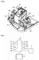
- Fig. 6 is a perspective view of a processing room 60 for performing lens processing.
- the first processing tool 168, lens shape measuring unit 200, second processing tool 430, third processing tool 440, lens chuck shafts 102L, 102R and the like are arranged within the processing room 60.
- Various driving devices such as the motors 110, 120, 145, 150, 160, 421, 471, 482 are arranged outside the processing room for eyeglass lens processing. Since the driving devices are arranged outside the processing room 60 in this manner, water to be used in processing can be restricted from invading into the driving devices. This can reduce the failure of the apparatus.
- the second and third processing tools 430 and 440 use a driving device (for example, the motor 421) in common to thereby reduce the number of driving devices and the driving devices are arranged outside the processing room 60, the possibility of the apparatus failure can be reduced further.
- Fig. 7 is a control block diagram relating to the eyeglass lens processing apparatus 1.
- a non-volatile memory (memory device) 51 a lens hold part (lens hold unit) 100, a lens shape measuring unit 200, a first processing tool unit 300, a second processing tool unit 400 and a display 5 are connected to a control part 50.
- the control part 50 includes, for example, a CPU (processor), a RAM and a ROM.
- the CPU of the control part 50 controls the whole apparatus including the respective parts and the driving devices (for example, the motors 110, 120, 145, 150, 160, 421, 471 and 482) of the respective units.
- the RAM stores various kinds of information temporarily.
- the ROM of the control part 50 stores various programs, initial values and the like for controlling the operation of the whole apparatus.
- the control part 50 may also be constituted of multiple control parts (that is, multiple processors).
- the non-volatile memory (memory device) 51 is a non-transient memory medium which can hold storage contents even when supply of power is cut off.
- the non-volatile memory (memory) 51 there can be used, for example, a hard disk drive, a flash ROM and a USB memory removably mounted on the eyeglass lens processing apparatus 1.
- a touch-panel type display is used as the display 5.
- the display 5 when the display 5 is a touch panel, the display 5 functions as an operation part (operation unit).
- the control part 50 receives an input signal by a touch panel function owned by the display 5 to control the display of the figures, information and the like of the display 5.
- the eyeglass lens processing apparatus 1 includes an operation part.
- the operation part any one of a mouse, a joystick, a keyboard, a touch panel and the like may be used.
- description is given with reference to a structure in which the display 5 functions as an operation part.
- the eyeglass lens processing apparatus 1 is connected to an eyeglass frame shape measuring apparatus 2 (see, for example, the JP2012-185490A ).
- the eyeglass lens processing apparatus 1 receives various data obtained by the eyeglass frame shape measuring apparatus 2 (the details of which are described later).
- the eyeglass lens processing apparatus 1 and eyeglass frame shape measuring apparatus 2 may also be integrally constituted.
- the measuring mechanism of the eyeglass frame shape measuring apparatus 2 is arranged in the eyeglass lens processing apparatus 1.
- the memory 51 stores conditions for lens rotation speeds and grindstone speeds in roughing, finishing and polishing steps. It also stores processing conditions in every processing modes (for example, processing tool rotation speeds, processing tool moving speeds and the like).
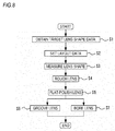
- Fig. 8 is a flow chart of an example of the control operation.
- the target lens shape data are obtained by the eyeglass frame shape measuring apparatus 2.
- this is not limitative.
- an operator after removing a demonstration lens mounted on the eyeglass frame, reads the contour of the demonstration lens using a contour read device or the like to thereby measure the target lens shape data.
- a data transmission switch not shown
- the target lens shape data are transmitted from the eyeglass frame shape measuring apparatus 2.
- this is not limitative.
- there may also be employed a structure in which, by an operator operating the display 5 of the eyeglass lens processing apparatus 1, the target lens shape data are input.
- the control part 50 displays a layout data setting screen for setting layout data with respect to the target lens shape data.
- various processing conditions can be set (S2). For example, an operator operates the display 5 to set lay-out data such as the inter-pupil distance of an eyeglass wearer (PD value), the distance between the frame centers of the eyeglass frame F (FPD value), and the height of the optical center OC of the target lens shape with respect to the geometrical center FC thereof.
- PD value inter-pupil distance of an eyeglass wearer
- FPD value distance between the frame centers of the eyeglass frame F
- FC the height of the optical center OC of the target lens shape with respect to the geometrical center FC thereof.
- an operator by operating the display 5, sets the material of the lens, the kind of the frame and processing conditions for processing modes (such as beveling, grooving and boring).
- the material of the lens for example, plastics and polycarbonate can be chosen.
- this embodiment there is shown a structure in which, in the eyeglass lens processing apparatus 1, by operating the display 5, the layout data are set.
- layout data are set in other apparatus or a PC (personal computer) and the eyeglass lens processing apparatus 1 (in this embodiment, the control part 50) receives the thus set layout data to thereby obtain the layout data.
- PC personal computer
- the operator allows the lens chuck shafts 102R, 102L to hold the lens LE.
- a processing start switch (not shown) displayed on the display 5 is chosen by the operator, the control part 50 starts the processing of the periphery of the lens LE.
- the control part 50 operates the lens edge position measuring parts 200F, 200R to measure the edge positions of the lens front and back surfaces based on the target lens shape data. According to the lens edge position measurement, it is confirmed whether the diameter of an un-processed lens LE is short or not with respect to the target lens shape.
- the control part 50 starts roughing (S4).
- the control part 50 For roughing the lens LE periphery, the control part 50, according to the target lens shape data and layout data, obtains processing control data (control data) for driving the respective parts.
- the control part 50 controls the driving of the X-axis moving motor 145 to arrange the lens LE on a rough grindstone 163.
- the control part 50 controls the driving of the Y-axis moving motor 150 while rotating the lens LE using the motor 120.
- the periphery of the lens LE is roughened by multiple times of rotations of the lens LE.
- the processing is transferred to finishing (in this embodiment, flat-finishing).
- the control part 50 according to the target lens shape data and layout data, obtains flat-finishing control data for flat-finishing the lens periphery.
- the control part 50 controls the driving of the X-axis moving motor 145 to arrange the lens LE on the flat-finishing surface of a finishing grindstone 164.
- the control part 50 controls the driving of the Y-axis moving motor 150 to flat-finish the lens LE using the finishing grindstone 164.
- the processing is transferred to a next processing. For example, when a grooving mode is set, the processing is transferred to the grooving mode. Also, when a boring mode is set, the processing is transferred to the boring mode.
- the control part 50 obtains grooving data (the rotation of the lens chuck shafts, control data on the X-direction movement thereof, control data on the Y-direction movement thereof, the first turn angle ⁇ about the first rotation shaft A1, and the second turn angle ⁇ about the second rotation shaft A2) and, according to the grooving data, grooving is performed (S6).
- the second turn angle ⁇ about the second rotation shaft A2 is set for 0°. That is, the third processing tool 440 is held at the retreat position.
- the third processing tool 440 is prevented from interfering with other parts.
- the second turn angle ⁇ about the second rotation shaft A2 in processing using the second processing tool 430 may be set such that, in grooving by the second processing tool 430, the third processing tool 440 is held at a position where it is prevented from interfering with other parts.
- Fig. 9 is a view to explain the grooving.
- L1 shows an axis parallel to the lens chuck shafts 102R, 102L.
- the initial position of the first turning unit 470 is set at a position where the processing tool drive shaft 430a with the second processing tool 430 mounted thereon is parallel to the lens chuck shafts 102R, 102L. That is, L1 is an axis which, when the first turning unit 470 is retained at the initial position, is parallel to the processing tool drive shaft 430a with the second processing tool 430 mounted thereon.
- L2 shows the axis of the processing tool drive shaft 430a when the first turning unit 470 turns the second processing tool 430 by the first turn angle ⁇ about the first rotation shaft A1. That is, in Fig. 9 , the first turning unit 470 has turned by the first turn angle ⁇ . Thus, the second processing tool 430 (processing tool drive shaft 430a) has been turned by the first turn angle ⁇ .
- the control part 50 drives the motor 471 and, according to the grooving data (the first turn angle ⁇ obtained), turns the second processing tool 430 by the first turn angle ⁇ about the first rotation shaft A1 to thereby control it to move to the processing position. That is, the control part 50, while controlling the first turning unit 470 such that an angle between the lens chuck shafts 102R, 102L and the processing tool drive shafts of the respective processing tools provides the first turn angle ⁇ obtained, turns the second and third processing tools 430 and 440. Then, the control part 50, while driving the motors 145 and 150, moves the carriage 101 in the XY direction to position the lens LE on the second processing tool 430.
- control part 50 rotates the motor 421 in a normal direction, whereby the rotation of the motor 421 is transmitted only to the processing tool drive shaft 430a and thus only the second processing tool 430 is rotated. Then, the control part 50, according to the grooving data, controls the movement of the carriage 101 in the XY direction, the rotation of the lens LE, and the first turn angle ⁇ of the processing tool drive shaft 430a of the second processing tool 430, whereby the lens LE is pressed against the second processing tool 430 for grooving the periphery of the lens LE.
- such grooving may also be performed, for example, in such a manner that, while changing the turn angles of the second processing tool 430 at the respective grooving points and also rotating the lens LE by moving the carriage 101 in the Y-axis direction and in the X-axis direction, the lens LE is pressed against the rotating second processing tool 430.
- This structure enables grooving to the curve of the lens and prevents the width of the groove from being processed widely.
- the sequence of the control (operation) of such grooving may be arbitrary. Of course, multiple controls may also be made simultaneously.
- Fig. 10 is an explanatory view of boring performed by turning of the second turning unit 480.
- Fig. 11 is an explanatory view of boring performed by turning of the first turning unit 470.
- Figs. 10 and 11 for convenience, show a case where boring is performed in the lens LE to be processed.
- L3 shows a line connecting together the second rotation shaft A2 and processing tool drive shaft 440a when the second turning unit 480 is retained at the initial position.
- an initial position before turning by the second turning unit 480 is set at a position where the processing tool drive shaft 440a of the third processing tool 440 is situated below the processing tool drive shaft 430a of the second processing tool 430.
- L4 shows a line connecting together the second rotation shaft A2 and processing tool drive shaft 440a when the second turning unit 480 turns the third processing tool 440 (processing tool drive shaft 440a) by the second turn angle ⁇ about the second rotation shaft A2. For example, when the second turn angle ⁇ of the second turning unit 480 is obtained, the third processing tool 440 (processing tool drive shaft 440a) is turned by the second turn angle ⁇ obtained.
- L5 shows a line parallel to the lens chuck shafts 102R, 102L.
- the initial position of the first turning unit 470 is set at a position where the processing tool drive shaft 440a with the third processing tool 440 mounted thereon is parallel to the lens chuck shafts 102R, 102L. That is, L5, when the first turning unit 470 is retained at the initial position, is an axis parallel to the processing tool drive shaft 440a with the third processing tool 440 mounted thereon.
- L6 shows the axis of the processing tool drive shaft 440a when the first turning unit 470 turns the third processing tool 440 by the first turn angle ⁇ about the first rotation shaft A1. That is, in Fig. 11 , the first turning unit 470 has turned by the first turn angle ⁇ . That is, the third processing tool 440 (processing tool drive shaft 440a) has been turned by the first turn angle ⁇ .
- the control part 50 obtains boring data (the rotation of the lens chuck shafts 102R, 102L, X-direction movement control data, Y-direction movement control data, first turn angle ⁇ about the first rotation shaft A1, the second turn angle ⁇ about the second rotation shaft A2) and, according to such boring data, bores the lens (S7).
- boring data the rotation of the lens chuck shafts 102R, 102L, X-direction movement control data, Y-direction movement control data, first turn angle ⁇ about the first rotation shaft A1, the second turn angle ⁇ about the second rotation shaft A2
- the boring data may only be obtained at least according to the boring data.
- the boring data is obtained by measuring a demonstration lens (dummy lens) by the eyeglass frame shape measuring apparatus 2.
- the demonstration lens is photographed and a hole is detected from the photographed demonstration lens, thereby obtaining the boring data.
- a structure for obtaining the boring data is not limited to the structure for measuring the demonstration lens.
- the boring data may also be obtained by a structure in which an operator operates and inputs the display 5.
- the boring data may be at least one of boring position data and boring direction data.
- the boring position data and boring direction data is obtained as the boring data.
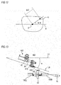
- Fig. 12 is an explanatory view of the boring position data.
- Fig. 13 is an explanatory view of the boring direction data.
- the boring position data of a hole P1 formed on the lens is obtained as polar coordinates ( ⁇ , ⁇ d) with respect to the geometrical center of the lens LE (or, the optical center of the lens LE).
- the reference of ⁇ is defined as a horizontal direction H in a state where an eyeglass wearer wears an eyeglass frame.
- the boring position data may also be expressed by an orthogonal coordinate system.
- the boring direction data represent the tilt direction of a hole.
- the boring direction data are obtained as the tilt angle ⁇ of the hole center axis PL passing through the center of a hole P1 in the lens LE with respect to the lens chuck shafts 102R, 102L.
- the boring direction data may also be set with respect to other reference different from the lens chuck shafts 102R, 102L.
- the control part 50 obtains the first turn angle ⁇ and second turn angle ⁇ which allow the hole center axis PL passing through the center of a hole P1 in the lens LE and processing tool drive shaft 440a to be parallel to each other. Firstly, according to the boring direction data, the control part 50 operates the first turn angle ⁇ such that the tilt angle ⁇ and first turn angle ⁇ coincide with each other. Next, according to the boring position data, the control part operates the second turn angle ⁇ , and the rotation amounts, X-direction moving amounts and Y-direction moving amounts (driving amounts) of the lens chuck shafts 102R, 102L. Here, the boring position data are converted to the XY-direction data of the apparatus before they are used. In the above-mentioned manner, the boring processing data are operated.
- the control part 50 bores the lens according to the obtained boring data. For example, while controlling the driving of the boring tool drive shaft according to any one of the first turn angle ⁇ and second turn angle ⁇ , it bores the lens.
- it when, in the obtained boring data, at least any one of the first turn angle ⁇ and second turn angle ⁇ is 0°, it bores the lens without driving the turning unit for which the turn angle of 0° is obtained.
- the first turn angle ⁇ is 0°. Therefore, it does not drive the first turning unit 470 from the initial position.
- the control part 50 controls the driving of the first turning unit 470 according to the obtained first turn angle ⁇ . That is, it drives the motor 471 to turn the third processing tool 440 by the first turn angle ⁇ about the first rotation shaft A1, thereby adjusting the position of the third processing tool 440. Also, it controls the driving of the second turning unit 480 according to the obtained second turn angle ⁇ . That is, it drives the motor 482 to turn the third processing tool 440 by the second turn angle ⁇ about the second rotation shaft A2, thereby adjusting the position of the third processing tool 440.
- the control part 50 rotates the motor 421 in the reverse direction, whereby the rotation of the motor 421 is transmitted to the processing tool drive shaft 440a to rotate the third processing tool 440.
- the boring data the rotation amounts of the lens chuck shafts 102R, 102L
- it rotates the lens chuck shafts 102R, 102L.
- the boring data X-direction moving amount, Y-direction moving amount
- it drives the motors 145 and 150 to move the carriage 101 in the XY direction, thereby allowing the third processing tool 440 to bore the lens. That is, the lens is bored by XY moving the carriage 101 in the axial direction of the processing tool drive shaft 440a of the third processing tool 440.
- the operation of the boring there can be used the boring operation disclosed in the JP2003-145328A .
- first and second turn angle directions When the boring operation is performed while the driving operations in the two turning directions (first and second turn angle directions) are combined, holes can be bored in an arbitrary direction. That is, arbitrary boring operations can be performed suitably.
- Use of the two first and second turning units 470 and 480 enables the processing tool drive shafts of the boring tools to turn in the two directions. This eliminates the need, as in the conventional technology, to move linearly (drive linearly) the processing tool drive shafts of the boring tools for boring a hole in an arbitrary direction, thereby eliminating a space for a mechanism for moving linearly the processing tool drive shafts of the boring tools. This enables miniaturization of the apparatus. Also, as in this embodiment, due to employment of a structure in which the first turning unit 470 is allowed to turn the boring tool (third processing tool 440) and further the second turning unit 480, arbitrary boring can be performed with a further simplified structure.
- an eyeglass lens processing apparatus may have any structure so long as it can perform a driving operation with two turning directions (first and second turn angle directions) combined.
- a structure including two or more turning units or, a structure capable of moving one boring tool in a three-dimensional direction. That is, the structure may be capable of moving on a space (area) formed (combined) by a turning area about a first rotation shaft and a turning area about a second rotation shaft.
- the second and third processing tools 430 and 440 use the driving device (for example, the motor 421) in common.
- driving devices are provided separately for the second and third processing tools 430 and 440.
- turning units may also be provided separately for the second and third processing tools 430 and 440.
- the second and third processing tools 430, 440 may also be used in common with the turning units.
- the control part 50 of the eyeglass lens processing apparatus 1 obtains the first turn angle ⁇ and second turn angle ⁇ for boring.
- a structure for obtaining the first turn angle ⁇ and second turn angle ⁇ may also be replaced with a structure which is provided by other eyeglass lens processing control data acquisition apparatus.
- the control part of the eyeglass lens processing control data acquisition apparatus obtains boring data with respect to the lens LE. According to the obtained boring data, it obtains the first turn angle ⁇ of a processing tool drive shaft with the boring tool mounted thereon about the first rotation shaft A1 and the second turn angle ⁇ of the processing tool drive shaft with the boring tool mounted thereon about the second rotation shaft A2 different from the first rotation shaft A1.
- the boring processing data including the obtained first turn angle ⁇ and second turn angle ⁇ are transmitted to an eyeglass lens processing apparatus including a boring tool.
- the eyeglass lens processing apparatus controls the boring tool according to the boring processing data to thereby bore the lens.
- eyeglass lens processing software for performing the function of the above embodiment can be supplied to a system or an apparatus through network or various storage mediums; and, the computer (for example, CPU) of the system or apparatus can read out the program and execute it.
Landscapes
- Engineering & Computer Science (AREA)
- Mechanical Engineering (AREA)
- Chemical & Material Sciences (AREA)
- Ceramic Engineering (AREA)
- Inorganic Chemistry (AREA)
- Mining & Mineral Resources (AREA)
- Grinding And Polishing Of Tertiary Curved Surfaces And Surfaces With Complex Shapes (AREA)
Abstract
a first rotation shaft (A1) to enable rotation of the boring tool drive shaft (440a) about a first turn angle (alpha), and a second rotation shaft (A2) to enable rotation of the boring tool drive shaft (440a) about a second turn angle (beta), a turn angle acquisition means (50) configured to obtain, according to the boring data, a first turn angle (alpha) of the boring tool drive shaft about a first rotation shaft (A1) and a second turn angle (beta) of the boring tool drive shaft about a second rotation shaft (A2) different from the first rotation shaft (A1); and control means (50) configured to control the driving of the boring tool drive shaft (440a) to bore the eyeglass lens according to at least any one of the first (alpha) and second (beta) turn angles.
Description
- The invention relates to an eyeglass lens processing apparatus for boring eyeglass lens, an eyeglass lens processing control data acquisition apparatus for acquiring processing control data for processing boring eyeglass lens, an eyeglass lens processing method for boring eyeglass lens, and an eyeglass lens processing program.
- There is known an eyeglass lens processing apparatus for processing the periphery of a lens (eyeglass lens) so as to correspond to the shape of an eyeglass frame using a grinding tool (grindstone, cutter). In a so-called two-point frame (rimless eyeglass), a lens after periphery working is bored. For boring an eyeglass lens, there is proposed an eyeglass lens processing apparatus capable of automatically boring the lens using numerical value control (see, for example,
JP 2003-145328A - Firstly, conventionally, in eyeglasses, while controlling a boring tool in combination with the operations of a linearly moving mechanism (linear motion mechanism) and a turning movement mechanism (turning mechanism) to thereby adjust the position relationship between an eyeglass lens and boring tool, the lens is bored. However, the linear movement of the boring tool requires a larger space.
- The invention, in view of the above-mentioned first problem of the conventional technology, has a technological object to provide an eyeglass lens processing apparatus, an eyeglass lens processing method and an eyeglass lens processing program which can perform an arbitrary boring operation suitably. The invention also has a technological object to provide an eyeglass lens processing control data acquisition apparatus for obtaining processing control data suitable for performing the arbitrary boring operation.
- Secondly, the above apparatus needs many structures for driving transport devices to adjust the position of the processing tools, resulting in the upsizing of the apparatus. Also, control of many structures requires complicated control.
- The invention, in view of the above second problem of the conventional technology, has an object to provide an eyeglass lens processing apparatus capable of driving multiple processing tools with a simple structure.
- In attaining the above objects, the invention has the following structures.
- (1) An eyeglass lens processing apparatus for boring an eyeglass lens, comprising:
- a boring tool (440) configured to bore the eyeglass lens;
- a boring tool drive shaft (440a) configured to drive the boring tool (440);
- a boring data acquisition means (50) configured to obtain boring data with respect to the eyeglass lens;
- a turn angle acquisition means (50) configured to obtain, according to the boring data, a first turn angle (α) of the boring tool drive shaft about a first rotation shaft (A1) and a second turn angle (β) of the boring tool drive shaft about a second rotation shaft (A2) different from the first rotation shaft (A1); and
- control means (50) configured to control the driving of the boring tool drive shaft to bore the eyeglass lens according to at least any one of the first and second turn angles.
- (2) The eyeglass lens processing apparatus according to (1) further comprising:
- a first turning part (470) configured to turn the boring tool drive shaft about the first rotation shaft; and
- a second turning part (480) configured to turn the boring tool drive shaft about the second rotation shaft,
- (3) The eyeglass lens processing apparatus according to (1) further comprising:
- a first turning part having a first motor (471), the first turning part being configured to turn the boring tool drive shaft about the first rotation shaft by controlling the driving of the first motor; and
- a second turning part having a second motor (482), the second turning part being configured to turn the boring tool drive shaft about the second rotation shaft by controlling the driving of the second motor,
- (4) The eyeglass lens processing apparatus according to (2) or (3), wherein the first turning part turns the second rotation shaft together with the boring tool drive shaft.
- (5) An eyeglass lens processing apparatus according to any one of (1) to (4), wherein the second rotation shaft is perpendicular to the first rotation shaft.
- (6) An eyeglass lens processing apparatus according to any one of (1) to (5), wherein the turn angle acquisition means obtains the first and second turn angles that make a hole axis (PL) passing through the center of a hole in the eyeglass lens and the boring tool drive shaft parallel to each other.
- (7) The eyeglass lens processing apparatus according to any one of (1) to (6), further comprising:
- a first processing tool rotation shaft (430a) configured to rotate a first processing tool (430) different from the boring tool;
- a drive means (421) configured to rotate a drive shaft (400a) in normal and reverse directions;
- a rotation transmission mechanism (432, 438, 441, 442, 435, 437) having a clutch (490) and configured to transmit the rotation of the drive shaft to the first processing tool rotation shaft when the drive shaft is rotated in one of normal and reverse directions, and transmit the rotation of the drive shaft to at least the boring tool drive shaft when the drive shaft is rotated in the other direction; and
- a drive control means (50) for controlling the rotation direction of the drive means to switch from one of the first processing tool rotation shaft and the second boring tool drive shaft to the other of the first processing tool rotation shaft and the second boring tool drive shaft.
- (8) An eyeglass lens processing control data acquisition apparatus for obtaining processing control data for boring an eyeglass lens, comprising:
- a data acquisition means (50) for obtaining boring data with respect to the eyeglass lens; and
- a turn angle acquisition means (50) for obtaining a first turn angle (α) of the boring tool drive shaft about a first rotation shaft (A1) and a second turn angle (β) of the boring tool drive shaft about a second rotation shaft (A2) according to the boring data.
- (9) An eyeglass lens processing apparatus for boring an eyeglass lens, comprising:
- lens rotation means (100a) for rotating lens chuck shaft (102L, 102R) for holding the eyeglass lens;
- chuck shaft drive means (100b) for moving the lens chuck shafts in the axial direction;
- a processing tool drive shaft (440a) for rotating a boring tool (440) for boring the eyeglass lens; a boring data acquisition means (50) for obtaining boring data with respect to the eyeglass lens;
- shaft-to-shaft distance adjusting means (100c) for adjusting the shaft-to-shaft distance between the lens chuck shaft and the boring tool drive shaft;
- a first turning part (470) for turning the boring tool drive shaft about a first rotation shaft (A1);
- a second turning part (480) for turning the boring tool drive shaft about a second rotation shaft (A2);
- turn angle acquisition means (50) for obtaining, according to the boring data, a first turn angle (α) of the first turning part and a second turn angle (β) of the second turning part, the obtained first turn angle and the obtained second turn angle making a hole axis (PL) passing through the center of a hole in the eyeglass lens and the boring tool drive shaft parallel to each other;
- rotation amount acquisition means (50) for obtaining a rotation amount of the lens rotation means according to the boring data;
- drive amount acquisition means (50) for obtaining a drive amount of the shaft-to-shaft distance adjusting means according to the boring data;
- moving amount acquisition means (50) for obtaining a moving amount of the chuck shaft moving device according to the boring data; and
- control means (50) for controlling driving of the boring tool drive shaft and the lens chuck shafts for boring according to the obtained first turn angle, the obtained second turn angle, the obtained rotation amount, the obtained drive amount and the obtained moving amount.
- (10) An eyeglass lens processing method for boring an eyeglass lens, comprising:
- a boring data acquisition step of obtaining boring data with respect to the eyeglass lens;
- a turn angle acquisition step of obtaining a first turn angle (α) of a processing tool drive shaft for driving a boring tool (440) for boring the eyeglass lens about a first rotation shaft (A1) and a second turn angle (β) of the boring tool drive shaft about a second rotation shaft (A2) different from the first rotation shaft according to the boring data; and
- a control step of controlling the driving of the boring tool drive shaft for boring according to at least any one of the first and second turn angles.
- (11) An eyeglass lens processing apparatus, comprising:
- a first processing tool (430) configured to process an eyeglass lens;
- a second processing tool (440) configured to process the eyeglass lens, the second processing tool being different from the first processing tool;
- a first processing tool rotation shaft (430a) for rotating the first processing tool (430);
- a second processing tool rotation shaft (440a) for rotating the second processing tool (440);
- a drive means (421) configured to rotate a drive shaft (400a) in normal and reverse directions;
- a rotation transmission mechanism (432, 438, 441, 442, 435 and 437) including a clutch (490), the rotation transmission mechanism being configured to transmit the rotation of the drive shaft to the first processing tool rotation shaft when the drive shaft is rotated in one of normal and reverse directions, and transmit the rotation of the drive shaft to at least the second processing tool rotation shaft when the drive shaft is rotated in the other direction; and
- a drive control means (50) for controlling the rotation direction of the drive means to switch from one of the first processing tool rotation shaft and the second boring tool drive shaft to the other of the first processing tool rotation shaft and the second boring tool drive shaft.
- (12) The eyeglass lens processing apparatus according to (11), wherein the first processing tool rotation shaft is arranged coaxially with the drive shaft and the second processing tool rotation shaft is arranged at a position different from the axis of the drive shaft.
- (13) The eyeglass lens processing apparatus according to (11) or (12),
wherein by directly connecting the first processing tool rotation shaft to the drive shaft, the drive transmission mechanism transmits the rotation of the drive shaft to the first processing tool rotation shaft, and
wherein by connecting the first processing tool rotation shaft to the drive shaft through the clutch, the drive transmission mechanism transmits the rotation of the drive shaft to the second processing tool rotation shaft. - (14) The eyeglass lens processing apparatus according to any one of (11) to (13),
wherein the first processing tool is a finishing tool for finishing a periphery of the eyeglass lens,
wherein the second processing tool is a boring tool for boring the eyeglass lens, and
wherein the drive transmission mechanism transmits the rotation of the drive shaft to the first processing tool rotation shaft such that the rotation direction of the first processing tool rotation shaft is made identical with the rotation direction of the lens chucks for holding the eyeglass lens. -
-
Fig. 1 is a schematic structure view of a processing mechanism part of an eyeglass lens processing apparatus. -
Figs. 2A and 2B are schematic structure views of the appearance of a second processing tool unit. -
Fig. 3 is a section view of the second processing tool unit. -
Fig. 4 is an enlarged view of a processing tool part in the section view of the second processing tool unit. -
Fig. 5 is an explanatory view of the structure of a one-way clutch. -
Fig. 6 is a perspective view of a processing chamber for lens processing. -
Fig. 7 is a control block diagram of the eyeglass lens processing apparatus. -
Fig. 8 is a flow chart to explain an example of a control operation. -
Fig. 9 is an explanatory view of how to groove a lens. -
Fig. 10 is an explanatory view of how to bore a lens through turning of a second turning unit. -
Fig. 11 is an explanatory view of how to bore a lens through turning of a first turning unit. -
Fig. 12 is an explanatory view of boring position data. -
Fig. 13 is an explanatory view of boring direction data. - Description is given below of an embodiment of the invention with reference to the drawings.
Fig. 1 is a schematic structure view of a processing mechanism part of an eyeglass lens processing apparatus. - For example, the eyeglass
lens processing apparatus 1 includes alens hold part 100, a lens shape measuring unit 200, a firstprocessing tool unit 300 and a secondprocessing tool unit 400. Specifically, the lens holdpart 100 includeslens chuck shafts processing tool unit 300 rotates a processing tool rotation shaft (grindstone spindle) 161a mounting thereon afirst processing tool 168 for processing the periphery of the lens. The secondprocessing tool unit 400 includes asecond processing tool 430 and athird processing tool 440 for processing the periphery of the lens. - The lens hold
part 100 includes alens rotating unit 100a, a chuckshaft moving unit 100b, and a shaft-to-shaftdistance change unit 100c. Thelens rotating unit 100a rotates a pair oflens chuck shafts - The chuck shaft moving unit (X-direction moving unit) 100b moves the lens chucks 102R, 102L in the axial direction (which is defined as an X direction). The shaft-to-shaft distance change unit (Y-direction moving unit) 100c moves the lens chucks 102R, 102L in a direction (Y direction) to come near to or part away from the
grindstone spindle 161a, a processingtool drive shaft 430a with the secondlens processing tool 430 mounted thereon, or a processingtool drive shaft 440a with the thirdlens processing tool 440 mounted thereon. Also, the Y-direction moving unit 100c is used also as a lens moving unit which moves the lens LE relatively in a direction to change the distance between thelens chuck shafts lens chuck shafts - Description is given below specifically of a specific example of the processing apparatus
main body 1. The processing apparatusmain body 1 mounts the lens holdpart 100 on thebase 170 thereof. Thelens chuck shaft 102L andlens chuck shaft 102R are rotatably and coaxially held on theleft arm 101L andright arm 101R of thecarriage 101 of the lens holdpart 100 respectively. Thelens chuck shaft 102R is moved toward thelens chuck shaft 102L by amotor 110 mounted on theright arm 101R, whereby the lens LE is held by the twolens chuck shafts lens chuck shafts motor 120 mounted on theright arm 101R. These composing elements constitute thelens rotating unit 100a. - The
carriage 101 is mounted on an X-axismovement support base 140 movable alongshafts lens chuck shafts grindstone spindle 161a. On the rear portion of thesupport base 140, there is mounted a ball screw (not shown) extending in parallel to theshaft 103, while the ball screw is mounted on the rotation shaft of theX-axis moving motor 145. When themotor 145 rotates, thecarriage 101 together with thesupport base 140 is moved linearly in the X direction (the axial direction of the lens chuck shaft). This constitutes theX-direction moving unit 100b. Themotor 145 has, on the rotation shaft thereof, an encoder (not shown) serving as a detector for detecting the X-direction movement of thecarriage 101. - Also, in this embodiment, the X-direction moving positions of the lens chucks 102R, 102L to be detected by the encoder (not shown) serving as the detector are used when the refractive surface shapes of the front and back surfaces of the lens are obtained.
- A
shaft 156 extends in a direction where thelens chuck shafts grindstone rotation shaft 161 a are connected together and fixed to thesupport base 140. The Y-direction moving unit 100c is structured such that it can be moved in a direction (Y direction) where the shaft-to-shaft distance between thelens chuck shafts grindstone rotation shaft 161 a is changed about theshaft 103. The Y-direction moving unit of the apparatus is structured such that thelens chuck shafts shaft 103. However, the distance between thelens chuck shafts grindstone rotation shaft 161a may also be changed linearly. - A Y-
axis moving motor 150 is fixed to thesupport base 140. The rotation of themotor 150 is transmitted to aball screw 155 extending in the Y direction and, as theball screw 155 rotates, thecarriage 101 is moved in the Y direction. This constitutes the Y-direction moving unit 100c. Themotor 150 has, on the rotation shaft thereof, anencoder 158 serving as a detector for detecting the Y-direction movement of thecarriage 101. - In
Fig. 1 , the lens shape measuring unit 200 and secondprocessing tool unit 400 are disposed at positions existing above thecarriage 101 and opposite to the firstlens processing tool 168 through thecarriage 101. - Specifically, the lens shape measuring unit 200 is fixed to the
base 170 of the processing apparatusmain body 1. It includes a lens edgeposition measuring part 200F and a lens edgeposition measuring part 200R. The lens edgeposition measuring part 200F includes a tracing stylus to be contacted with the front surface of the lens LE, while the lens edgeposition measuring part 200R includes a tracing stylus to be contacted with the back surface of the lens LE. With the two tracing styluses of the lens edgeposition measuring parts carriage 101 is moved in the Y-axis direction and the lens LE is rotated, whereby the edge positions of the lens front and back surfaces for lens peripheral processing are measured simultaneously. The lens edgeposition measuring parts JP2003-145328A - The first
processing tool unit 300 is arranged, on thebase 170, opposed to (on the opposite side of) the lens shape measuring unit 200 across thecarriage 101. It includes afirst processing tool 168 which is one of the lens processing tools. Thefirst processing tool 168 is constituted of, for example, a rough grindstone forglass 162, a finishinggrindstone 164 having a V groove (a bevel groove) for forming a bevel in the lens and a flat processing surface, a flat-finishing grindstone 165, a finishinggrindstone 166 for finishing a lens with a high curve, a rough grindstone forplastics 167. Thefirst processing tool 168 is mounted coaxially on the grindstone rotation shaft (grindstone spindle) 161a which can be rotated by amotor 160. The lens LE held by the lens chuck shafts (lens rotation shafts) 102L, 102R of thecarriage 101 is pressure contacted with thefirst processing tool 168, whereby the periphery thereof is processed. Thefirst processing tool 168 has a large diameter, for example, a diameter of 60 ∼ 100 mm for roughing and finishing the lens periphery with high efficiency. Of course, grindstones having various diameters can be used for such large diameter of thefirst processing tool 168. -
Fig. 2 is a schematic structure view of the appearance of the secondprocessing tool unit 400.Fig. 2A is a top view of theunit 400 when viewed from the upper direction thereof (when viewed from above the sheet ofFig. 1 ).Fig. 2B is a side view of theunit 400.Fig. 3 is a section view of theunit 400.Fig. 4 is an enlarged view of a processing tool part in the section view of theunit 400. Theunit 400 includes asecond processing tool 430, athird processing tool 440, a first turning unit (first turning part) 470, a second turning unit (second turning part) 480, a drive part (motor) 421 and so on. Thethird processing tool 440 is connected to thesecond processing tool 430 by ahold part 410. Here, for example, the first turning unit is used as a first actuator, while the second turning unit is used as a second actuator. - The
second processing tool 430 is mounted on a drive shaft (processing tool drive shaft) 400a through a processingtool drive shaft 430a. In this embodiment, as thesecond processing tool 430, a finishing tool can be used. In this embodiment, as the finishing tool, a processing tool for grooving the periphery of the lens can be used. Of course, thesecond processing tool 430 is not limited to the grooving tool. There may also be used various processing tools (for example, a chamfering tool, a beveling tool, a processing tool for forming a step and a boring tool). - The
second processing tool 430 is connected to the processing tool drive shaft (for example, shaft) 430a. The processingtool drive shaft 430a is disposed within a second rotation shaft (for example, shaft) A2 which is discussed later, while it is supported rotatably on the second rotation shaft A2 by abearing 431. Of course, the number of bearings is not limitative. For example, the processingtool drive shaft 430a is connected to a processingtool drive shaft 400a of amotor 421 through a connectingmember 432, whereby thesecond processing tool 430 andmotor 421 are directly connected to each other. That is, in this embodiment, the processingtool drive shaft 430a of thesecond processing tool 430 and the processingtool drive shaft 400a of themotor 421 are coaxially arranged. Of course, they may also be arranged on different axes. - For example, as the
motor 421 rotates, thesecond processing tool 430 rotates about the processingtool drive shaft 430a. In this case, the processingtool drive shaft 430a of thesecond processing tool 430 provides a processing tool rotation shaft. While thesecond processing tool 430 is rotating, the lens periphery is processed by press contacting the lens LE held by the lens chuck shafts (lens rotation shafts) 102L, 102R of thecarriage 101 with thesecond processing tool 430. Here, in this embodiment, description is given of an example in which thesecond processing tool 430 rotates about the processingtool drive shaft 430a. However, this is not limitative. For example, thesecond processing tool 430 may also move on the axis of the processingtool drive shaft 430a in the back-and-forth direction (X direction) to thereby process the lens LE. Or, thesecond processing tool 430 may also be constituted of a light source for emitting laser beam and thus it may irradiate laser beam toward the lens LE to thereby process the lens LE. - The
third processing tool 440 is mounted on a processing tool drive shaft (for example, shaft) 440a. For example, in this embodiment, as thethird processing tool 440, a processing tool for boring the lens can be used. Of course, thethird processing tool 440 is not limited to the boring tool. Various processing tools (for example, a chamfering tool, a beveling tool, a processing tool for forming a step and a boring tool) can be also used. - The
third processing tool 440 is connected to a processing tool drive shaft (for example, shaft) 440a. The processingtool drive shaft 440a is supported rotatably on ahold part 410 by twobearings 441. Of course, the number of bearings is not limited to this. For example, the processingtool drive shaft 440a is connected through the processingtool drive shaft 430a to the processingtool drive shaft 400a of themotor 421. In this embodiment, the processingtool drive shaft 440a of thethird processing tool 440 is arranged at a position different from the axis of the processingtool drive shaft 400a of themotor 421. That is, the rotation of the processingtool drive shaft 400a of themotor 421 is transmitted to the processingtool drive shaft 440a of thethird processing tool 440 through a transmission member (for example, a one-way clutch to be discussed later). - For example, a
pulley 442 is mounted on the processingtool drive shaft 440a with thethird processing tool 440 thereon. For example, the processingtool drive shaft 430a with thesecond processing tool 430 mounted thereon is connected to a one-way clutch (which is hereinafter called a clutch) 490. For example, apulley 435 is mounted on the clutch 490. Abearing 438 is arranged behind the clutch 490 (in themotor 421 direction). Within thehold part 410, abelt 437 is extended between thepulleys motor 421 is transmitted to the processingtool rotation shaft 440a. Thus, the rotation of the processingtool drive shaft 400a of themotor 421 is transmitted to the processingtool rotation shaft 440a of thethird processing tool 440. Of course, as the structure for transmitting the drive of themotor 421 to the third processing tool, various structures can be employed. - While the relative position relationship between the lens LE held by the lens chuck shafts (lens rotation shafts) 102L, 102R of the
carriage 101 andthird processing tool 440 is adjusted, the lens LE is bored. In this embodiment, the processingtool drive shaft 440a with thethird processing tool 440 mounted thereon provides a processing tool rotation shaft enabling thethird processing tool 430 to rotate about the processingtool drive shaft 440a. Here, in this embodiment, description is given of an example in which, a processing tool enabling thethird processing tool 440 to rotate about the processing tool drive shaft can be used as thethird processing tool 440. However, this is not limitative. For example, thethird processing tool 440 may also be structured to move in the back-and-forth direction (the direction along the axis) on the axis of the processingtool drive shaft 440a to thereby process the lens. Or, it may also be a light source for emitting laser beam and thus may irradiate laser beam toward the lens to thereby process it. - Here, in this embodiment, a single drive means is used in common for the second and
third processing tools motor 421 is used in common as the drive source of the second andthird processing tools motor 431 can rotate the processingtool drive shaft 400a in normal and reverse directions. For example, in this embodiment, the secondprocessing tool unit 400 is structured such that, when the processingtool drive shaft 400a of themotor 421 is rotated in one of the normal and reverse directions, using the clutch 490, it transmits the rotation of the processingtool drive shaft 400a to the processingtool drive shaft 430a with thesecond processing tool 430 mounted thereon. Also, the secondprocessing tool unit 400 is structured such that, when the processingtool drive shaft 400a of themotor 421 is rotated in the other direction, using the clutch 490, it transmits the rotation of the processingtool drive shaft 400a at least to the processingtool drive shaft 440a with thethird processing tool 440 mounted thereon. Thus, by controlling the rotation direction of the processingtool drive shaft 400a of themotor 421, driving of the processingtool drive shaft 430a with thesecond processing tool 430 mounted thereon and driving of the processingtool drive shaft 440a with thethird processing tool 440 mounted thereon can be switched. Here, the rotation direction of the processingtool drive shaft 400a of themotor 421 and the rotation direction of the processingtool drive shaft 430a need not coincide with each other. For example, there may also be employed a structure in which the rotation direction of the processingtool drive shaft 400a of themotor 421 and the rotation direction of the processingtool drive shaft 430a are different. In this embodiment, the processingtool drive shaft 400a of themotor 421 and the processingtool drive shaft 430a are rotated in the same direction. - More specifically,
Fig. 5 is an explanatory view of the structure of the one-way clutch 490. The clutch 490 includes anouter ring 491, aneedle roller 492 and aspring 493. Theouter ring 491 has acam groove 494 and acam surface 495. In the clutch 490, the above-mentioned respective parts are arranged at specific intervals in the peripheral direction of theouter ring 491. For example, thepulley 435 is mounted on the outside 491a of theouter ring 491. This enables theouter ring 491 to rotate together with thepulley 435. The processingtool drive shaft 430a is connected to the inside 491b of theouter ring 491. Theneedle roller 492 is rollably arranged in acam groove 494 formed in theouter ring 491 and is energized toward the meshing position of thecam surface 495 by thespring 493. - For example, by driving the
motor 421 to rotate the processingtool drive shaft 430a in the left-handed direction (counterclockwise) together with the processingtool drive shaft 400a, due to the energization force of thespring 493, theneedle roller 492 is engaged between thecam surface 495 and processingtool drive shaft 430a (a state shown inFig. 5 ). Thus, together with rotation of theprocessing tool drive 430a, theouter ring 491 andpulley 435 are rotated. Also, due to rotation of thepulley 435, the rotation of thepulley 435 is transmitted to thepulley 442, whereby the processingtool drive shaft 440a with thepulley 442 mounted thereon is rotated. That is, the rotation of the processingtool drive shaft 440a is transmitted to the processingtool drive shaft 440a of thethird processing tool 440. Here, in this embodiment, the right-handed rotation (clockwise rotation) is defined as a normal direction rotation, whereas the counterclockwise rotation is defined as a reverse direction rotation. Also, in this embodiment, as the processingtool drive shaft 440a rotates, the processingtool drive shaft 430a also rotates. That is, when thethird processing tool 440 is rotated, thesecond processing tool 430 is also rotated. Of course, only thethird processing tool 440 may also be rotated. - Meanwhile, for example, when the
motor 421 is driven and the processingtool drive shaft 430a is thereby rotated in the right-handed direction (clockwise) together with the processingtool drive shaft 400a, theneedle roller 492 is disengaged from thecam surface 495 and theouter ring 491 rotates idly (the rotation thereof is reduced). That is, since theneedle roller 492 is disengaged from thecam surface 495, it is disengaged from the processingtool drive shaft 430a. Thus, the rotation of the processingtool drive shaft 430a is not transmitted to the processingtool drive shaft 440a. That is, transmission of the rotation to the third processing tool is restricted and the second processing tool is rotated. Thus, by employing a structure that, during processing by thesecond processing tool 430, thethird processing tool 440 is prevented against rotation, it is possible to restrict occurrence of a phenomenon that the rotation thereof facilitates invasion of water. - For example, this embodiment is structured such that, when processing the periphery of the lens LE using the
second processing tool 430, the rotation direction of the second processing tool 430 (processingtool drive shaft 430a) coincides with the rotation direction of thelens chuck shafts tool drive shaft 400a is transmitted to the processingtool drive shaft 430a such that the rotation direction of the processingtool drive shaft 430a coincides with the rotation direction of thelens chuck shafts tool drive shaft 430a with the rotation direction of thelens chuck shafts second processing tool 430 to up-cut process the periphery of the lens LE, whereby the lens periphery can have an excellent surface after it is processed by thesecond processing tool 430. That is, such up-cut processing of the lens periphery makes it hard for processed pieces produced in processing the lens LE periphery to attach to the processed portions of the lens LE. Therefore, the surface of the periphery of the lens LE after processed provides an excellent surface. Meanwhile, a boring tool hard to have an influence on a processed state depending on the rotation direction can be used as thethird processing tool 440. This can provide an apparatus which uses the normal direction rotation and reverse direction rotation more properly. Of course, there may also be employed a structure in which, when processing the periphery of the lens LE using thesecond processing tool 430, the rotation direction of the second processing tool 430 (processingtool drive shaft 430a) is reversed to the rotation direction of thelens chuck shafts - Here, in this embodiment, the processing
tool drive shaft 430a mounted on thesecond processing tool 430 and the processingtool drive shaft 440a mounted on thethird processing tool 440 are arranged in parallel. However, this is not limitative. - As described above, by switching the rotation direction of the drive means using the clutch, the processing tool to be driven for processing can be switched. This eliminates the need to equip processing tools with the drive means separately and thus eliminates complicated control. Also, multiple processing tools can be driven with a simple structure. And, elimination of the separate drive means enables downsizing of the apparatus.
- Here, this embodiment has been described heretofore with reference to the structure using a one-way clutch as the clutch 490. However, this is not limitative. As the clutch 490, various clutches can be applied. For example, an electromagnet clutch, a centrifugal clutch, or a fluid clutch may also be used. Here, use of a one-way clutch as a clutch enables switching of processing tools with a simple structure. Also, a one-way clutch does not need a larger space than other clutches, thereby enabling further miniaturization of the apparatus. Therefore, as the clutch 490, more preferably, the one-way clutch used in this embodiment may be used.
- As shown in
Fig. 2 , thefirst turning unit 470 includes, for example, a first rotation shaft (for example, shaft) A1, amotor 471, agear 472, agear 473, aprop 474, agear 475 and abase part 402. Themotor 471 in this embodiment is structured such that the drive shaft (rotation shaft) can be rotated in normal and reverse directions. The first rotation shaft A1 is arranged within thebase part 402 and is fixed to asupport base block 401. Thebase part 402 is connected to the first rotation shaft A1 through a bearing (not shown) and is held on thesupport base block 401 such that it can be turned about the first rotation shaft A1. Thegear 472 is mounted on the drive shaft of themotor 471. Thus, as themotor 471 is driven, thegear 472 is rotated together. Thegear 472 is engaged with thegear 473. Thegear 473 is connected to theprop 474. Theprop 474 has a gear part to be engaged with thegear 475. To thegear 475, there is connected thebase part 402. - For example, by rotating the
motor 471, the rotation of themotor 471 is transmitted to thebase part 402 through thegear 472,gear 473,prop 474 andgear 475. This enables thebase part 402 to turn about the first rotation shaft (for example, shaft). Of course, as the structure to transmit the rotation of themotor 471 to thebase part 402, there may be applied various structures. Here, in this embodiment, by switching the rotation direction of themotor 471, the rotation directions of the respective gears can be changed. Thus, the direction of turning of thebase part 402 about the first rotation shaft A1 can be switched. - In this manner, the
first turning unit 470 turns thebase part 402 about the first rotation shaft A1 relative to thesupport base block 401. Thesupport base block 401 is fixed to thebase 170. A second rotation shaft A2 is connected to thebase part 402. Thehold part 410,second processing tool 430,second turning unit 480 and the like are connected to the second rotation shaft A2. Here, thethird processing tool 440 is connected to the second rotation shaft A2 (second processing tool 430) through thehold part 410. Themotor 421 is connected to the second rotation shaft A2 through thesecond turning unit 480. - Due to the structure that various parts are mounted on the
base part 402 as mentioned above, thefirst turning unit 470 can turn thehold part 410,second processing tool 430,third processing tool 440,second turning unit 480,motor 421 and the like about the first rotation shaft A1. Here, thefirst turning unit 470 may have any structure so long as it can turn at least one of thesecond processing tool 430 andthird processing tool 440. In this embodiment, thefirst turning unit 470 is structured such that it turns various parts relative to thesupport base block 401. However, this is not limitative. Thefirst turning unit 470 may have any structure so long as it can change the relative position relationship between at least one of thesecond processing tool 430 andthird processing tool 440 andlens chuck shafts - The first rotation shaft A1 is arranged tilted 8° in the direction of the
lens chuck shafts lens chuck shafts lens chuck shafts - In this embodiment, the initial position of the
base part 402 before turning by thefirst turning unit 470 is set for a position where the processingtool drive shaft 430a with thesecond processing tool 430 mounted thereon is parallel to thelens chuck shafts lens chuck shafts first turning unit 470 is set such that, with the initial position 0°, the second andthird processing tools first processing tool 300. Of course, the turning range is not limited to this but can be set arbitrarily. - In this embodiment, the turning angle of (angle to be turned by) the
first turning unit 470 is adjusted by setting the positions of the processing tool drive shafts of the processing tools with respect to thelens chuck shafts third processing tools lens chuck shafts first turning unit 470 is adjusted. Here, in this embodiment, description is given of an example in which the turn angle is set with respect to thelens chuck shafts first turning unit 470 is adjusted with respect to the set position; for example, a structure in which the turn angle is set with respect to thesupport base block 401, and a structure in which the turn angle is set with respect to the lens shape measuring unit 200. - The
second turning unit 480 includes a second rotation shaft A2, abase part 481, amotor 482, abearing 483, abearing 484 and the like. Themotor 482 is fixed to thebase part 402. Here, in this embodiment, themotor 482 is structured such that the drive shaft (rotation shaft) thereof can be rotated in normal and reverse directions. The rotation of themotor 482 is transmitted to thebase part 481 through a gear (not shown), thereby rotating thebase part 481. Of course, there can be employed various structures for transmitting the rotation of themotor 482 to thebase part 481. The second rotation shaft A2 is arranged within thebase part 402 and is rotatably connected to thebase part 402 through thebearings - The
motor 421 and second rotation shaft A2 are fixed to thebase part 481. For example, the second rotation shaft A2 is fixed to the center of rotation of thebase part 481. That is, by transmitting the rotation of themotor 482 to thebase part 481, the second rotation shaft A2 andmotor 421 are rotated relative to thebase part 402 together with rotation of thebase part 481. - The
hold part 410,second processing tool 430 and the like are fixed to the second rotation shaft A2. Here, thethird processing tool 440 is connected through thehold part 410 to the second rotation shaft A2 (second processing tool 430). For example, the processingtool drive shaft 430a with thesecond processing tool 430 mounted thereon is coaxially arranged within the second rotation shaft A2. Thus, when the second rotation shaft A2 rotates together with rotation of thebase part 481, the hold part is rotated about the second rotation shaft A2, whereby thethird processing tool 440 held by thehold part 410 is turned about the second rotation shaft A2. That is, thesecond turning unit 480 can turn thethird processing tool 440 about the second rotation shaft A2. Here, thesecond turning unit 480 may have any structure so long as it can turn at least thethird processing tool 440. - In this embodiment, by switching the rotation direction of the
motor 482, the rotation directions of the respective gears can be changed. This can switch the rotation direction of thebase part 481 about the second rotation shaft A2. That is, by switching the rotation direction of themotor 482, the turning direction of thethird processing tool 440 is switched. - Here, in this embodiment, the
second turning unit 480 is described with reference to an example in which it turns various parts with respect to thebase part 402. However, this is not limitative. There may be employed any structure so long as thesecond turning unit 480 can change the relative position relationship between thethird processing tool 440 andlens chuck shafts - In this embodiment, the second rotation shaft A2 is arranged perpendicularly to the first rotation shaft A1. By arranging the two rotation shafts perpendicularly in this manner, the turn angle for adjusting the second
processing tool unit 400 at an arbitrary position when turning operations are performed by the first andsecond turning units - In this embodiment, the initial position of the third processing tool 440 (hold part 410) before turning by the
second turning unit 480 is set such that the processingtool drive shaft 440a of thethird processing tool 440 is situated below (just below in the Y direction) the processingtool drive shaft 430a of thesecond processing tool 430. Of course, the initial position may also be set at a different position. The range of turning by thesecond turning unit 480 is set such that, with the initial position 0°, thethird processing tool 440 can be turned by 90° in a direction toward the firstprocessing tool unit 300. Of course, the turning range is not limited to this but can be set arbitrarily. - Here, in this embodiment, when the
second processing tool 430 processes the lens LE, thethird processing tool 440 waits at the initial position. That is, in this embodiment, the initial position of thesecond turning unit 480 is set as the retreat position of thethird processing tool 440. Here, the retreat position is not limited to the initial position. The retreat position of thethird processing tool 440 may be set at any position so long as, while thesecond processing tool 430 is processing the lens LE, thethird processing tool 440 is prevented from interfering with other parts. Here, in processing by thethird processing tool 440, thesecond turning unit 480 is driven and thethird processing tool 440 is turned from the retreat position to a processing position. This enables thethird processing tool 440 to process the lens LE. -
Fig. 6 is a perspective view of aprocessing room 60 for performing lens processing. Thefirst processing tool 168, lens shape measuring unit 200,second processing tool 430,third processing tool 440,lens chuck shafts processing room 60. Various driving devices such as themotors processing room 60 in this manner, water to be used in processing can be restricted from invading into the driving devices. This can reduce the failure of the apparatus. Also, since the second andthird processing tools processing room 60, the possibility of the apparatus failure can be reduced further. - <Control Unit>
-
Fig. 7 is a control block diagram relating to the eyeglasslens processing apparatus 1. For example, a non-volatile memory (memory device) 51, a lens hold part (lens hold unit) 100, a lens shape measuring unit 200, a firstprocessing tool unit 300, a secondprocessing tool unit 400 and adisplay 5 are connected to acontrol part 50. - The
control part 50 includes, for example, a CPU (processor), a RAM and a ROM. The CPU of thecontrol part 50 controls the whole apparatus including the respective parts and the driving devices (for example, themotors control part 50 stores various programs, initial values and the like for controlling the operation of the whole apparatus. Here, thecontrol part 50 may also be constituted of multiple control parts (that is, multiple processors). The non-volatile memory (memory device) 51 is a non-transient memory medium which can hold storage contents even when supply of power is cut off. As the non-volatile memory (memory) 51, there can be used, for example, a hard disk drive, a flash ROM and a USB memory removably mounted on the eyeglasslens processing apparatus 1. - In this embodiment, a touch-panel type display is used as the
display 5. Here, when thedisplay 5 is a touch panel, thedisplay 5 functions as an operation part (operation unit). In this case, thecontrol part 50 receives an input signal by a touch panel function owned by thedisplay 5 to control the display of the figures, information and the like of thedisplay 5. Of course, there may also be employed a structure in which the eyeglasslens processing apparatus 1 includes an operation part. In this case, as the operation part, any one of a mouse, a joystick, a keyboard, a touch panel and the like may be used. Here, in this embodiment, description is given with reference to a structure in which thedisplay 5 functions as an operation part. - In this embodiment, the eyeglass
lens processing apparatus 1 is connected to an eyeglass frame shape measuring apparatus 2 (see, for example, theJP2012-185490A lens processing apparatus 1 receives various data obtained by the eyeglass frame shape measuring apparatus 2 (the details of which are described later). Of course, the eyeglasslens processing apparatus 1 and eyeglass frameshape measuring apparatus 2 may also be integrally constituted. In this case, for example, the measuring mechanism of the eyeglass frameshape measuring apparatus 2 is arranged in the eyeglasslens processing apparatus 1. - In this embodiment, the
memory 51 stores conditions for lens rotation speeds and grindstone speeds in roughing, finishing and polishing steps. It also stores processing conditions in every processing modes (for example, processing tool rotation speeds, processing tool moving speeds and the like). - Description is given of the operation of the eyeglass
lens processing apparatus 1 having the above structure. Here, in this embodiment, description is given with reference to an example using a grooving grindstone as thesecond processing tool 430 and a boring tool as thethird processing tool 440.Fig. 8 is a flow chart of an example of the control operation. - Target lens shape data are obtained by the eyeglass frame shape measuring apparatus 2 (S1). For example, by measuring an eyeglass frame by the eyeglass frame
shape measuring apparatus 2, the target lens shape data (rn, pn) (n=1, 2, 3,... N) of the lens frame are measured. By operating a data transmission switch (not shown) of the eyeglass frameshape measuring apparatus 2, the target lens shape data are transmitted from the eyeglass frameshape measuring apparatus 2 to the eyeglasslens processing apparatus 1 and are stored in thememory 51 of the eyeglasslens processing apparatus 1. - Here, in this embodiment, there is shown, as an example, a structure in which the target lens shape data are obtained by the eyeglass frame
shape measuring apparatus 2. However, this is not limitative. For example, there may also be employed a structure in which an operator, after removing a demonstration lens mounted on the eyeglass frame, reads the contour of the demonstration lens using a contour read device or the like to thereby measure the target lens shape data. Also, in this embodiment, there is shown a structure in which, by operating a data transmission switch (not shown) of the eyeglass frameshape measuring apparatus 2, the target lens shape data are transmitted from the eyeglass frameshape measuring apparatus 2. However, this is not limitative. For example, there may also be employed a structure in which, by an operator operating thedisplay 5 of the eyeglasslens processing apparatus 1, the target lens shape data are input. - On obtaining the target lens shape data, the
control part 50 displays a layout data setting screen for setting layout data with respect to the target lens shape data. On the layout data setting screen, various processing conditions can be set (S2). For example, an operator operates thedisplay 5 to set lay-out data such as the inter-pupil distance of an eyeglass wearer (PD value), the distance between the frame centers of the eyeglass frame F (FPD value), and the height of the optical center OC of the target lens shape with respect to the geometrical center FC thereof. Also, an operator, by operating thedisplay 5, sets the material of the lens, the kind of the frame and processing conditions for processing modes (such as beveling, grooving and boring). As the material of the lens, for example, plastics and polycarbonate can be chosen. Here, in this embodiment, there is shown a structure in which, in the eyeglasslens processing apparatus 1, by operating thedisplay 5, the layout data are set. However, this is not limitative. For example, there may also be employed a structure in which layout data are set in other apparatus or a PC (personal computer) and the eyeglass lens processing apparatus 1 (in this embodiment, the control part 50) receives the thus set layout data to thereby obtain the layout data. - Here, in this embodiment, description is given with reference to an example in which, as a processing mode, grooving (S6) or boring (S7) is set. In grooving, an operator operates the
display 5 to choose a grooving mode. In boring, the operator operates thedisplay 5 to choose a boring mode. - When the data necessary for lens processing are obtained in the above-mentioned manner, the operator allows the
lens chuck shafts display 5 is chosen by the operator, thecontrol part 50 starts the processing of the periphery of the lens LE. - Firstly, when the start switch is depressed, the
control part 50 operates the lens edgeposition measuring parts - On completion of the lens shape measurement, the
control part 50 starts roughing (S4). For roughing the lens LE periphery, thecontrol part 50, according to the target lens shape data and layout data, obtains processing control data (control data) for driving the respective parts. On obtaining the roughing control data, thecontrol part 50 controls the driving of theX-axis moving motor 145 to arrange the lens LE on a rough grindstone 163. After then, thecontrol part 50, according to the roughing control data, controls the driving of the Y-axis moving motor 150 while rotating the lens LE using themotor 120. The periphery of the lens LE is roughened by multiple times of rotations of the lens LE. - On completion of the roughing, the processing is transferred to finishing (in this embodiment, flat-finishing). The
control part 50, according to the target lens shape data and layout data, obtains flat-finishing control data for flat-finishing the lens periphery. Thecontrol part 50 controls the driving of theX-axis moving motor 145 to arrange the lens LE on the flat-finishing surface of a finishinggrindstone 164. After then, thecontrol part 50, according to the flat-finishing control data, controls the driving of the Y-axis moving motor 150 to flat-finish the lens LE using the finishinggrindstone 164. - On completion of the flat-finishing, the processing is transferred to a next processing. For example, when a grooving mode is set, the processing is transferred to the grooving mode. Also, when a boring mode is set, the processing is transferred to the boring mode.
- Description is given of the grooving mode. On completion of the finishing, the
control part 50, according to the target lens shape data and the shape data of the lens edge, obtains grooving data (the rotation of the lens chuck shafts, control data on the X-direction movement thereof, control data on the Y-direction movement thereof, the first turn angle α about the first rotation shaft A1, and the second turn angle β about the second rotation shaft A2) and, according to the grooving data, grooving is performed (S6). Here, in grooving, the second turn angle β about the second rotation shaft A2 is set for 0°. That is, thethird processing tool 440 is held at the retreat position. Thus, in grooving by thesecond processing tool 430, thethird processing tool 440 is prevented from interfering with other parts. Of course, the second turn angle β about the second rotation shaft A2 in processing using thesecond processing tool 430 may be set such that, in grooving by thesecond processing tool 430, thethird processing tool 440 is held at a position where it is prevented from interfering with other parts. -
Fig. 9 is a view to explain the grooving. For example, L1 shows an axis parallel to thelens chuck shafts first turning unit 470 is set at a position where the processingtool drive shaft 430a with thesecond processing tool 430 mounted thereon is parallel to thelens chuck shafts first turning unit 470 is retained at the initial position, is parallel to the processingtool drive shaft 430a with thesecond processing tool 430 mounted thereon. For example, L2 shows the axis of the processingtool drive shaft 430a when thefirst turning unit 470 turns thesecond processing tool 430 by the first turn angle α about the first rotation shaft A1. That is, inFig. 9 , thefirst turning unit 470 has turned by the first turn angle α. Thus, the second processing tool 430 (processingtool drive shaft 430a) has been turned by the first turn angle α. - The
control part 50 drives themotor 471 and, according to the grooving data (the first turn angle α obtained), turns thesecond processing tool 430 by the first turn angle α about the first rotation shaft A1 to thereby control it to move to the processing position. That is, thecontrol part 50, while controlling thefirst turning unit 470 such that an angle between thelens chuck shafts third processing tools control part 50, while driving themotors carriage 101 in the XY direction to position the lens LE on thesecond processing tool 430. - Next, the
control part 50 rotates themotor 421 in a normal direction, whereby the rotation of themotor 421 is transmitted only to the processingtool drive shaft 430a and thus only thesecond processing tool 430 is rotated. Then, thecontrol part 50, according to the grooving data, controls the movement of thecarriage 101 in the XY direction, the rotation of the lens LE, and the first turn angle α of the processingtool drive shaft 430a of thesecond processing tool 430, whereby the lens LE is pressed against thesecond processing tool 430 for grooving the periphery of the lens LE. Here, such grooving may also be performed, for example, in such a manner that, while changing the turn angles of thesecond processing tool 430 at the respective grooving points and also rotating the lens LE by moving thecarriage 101 in the Y-axis direction and in the X-axis direction, the lens LE is pressed against the rotatingsecond processing tool 430. This structure enables grooving to the curve of the lens and prevents the width of the groove from being processed widely. The sequence of the control (operation) of such grooving may be arbitrary. Of course, multiple controls may also be made simultaneously. - Description is given of a boring mode.
Fig. 10 is an explanatory view of boring performed by turning of thesecond turning unit 480.Fig. 11 is an explanatory view of boring performed by turning of thefirst turning unit 470. Here,Figs. 10 and 11 , for convenience, show a case where boring is performed in the lens LE to be processed. - In
Fig. 10 , L3 shows a line connecting together the second rotation shaft A2 and processingtool drive shaft 440a when thesecond turning unit 480 is retained at the initial position. Here, in this embodiment, an initial position before turning by thesecond turning unit 480 is set at a position where the processingtool drive shaft 440a of thethird processing tool 440 is situated below the processingtool drive shaft 430a of thesecond processing tool 430. L4 shows a line connecting together the second rotation shaft A2 and processingtool drive shaft 440a when thesecond turning unit 480 turns the third processing tool 440 (processingtool drive shaft 440a) by the second turn angle β about the second rotation shaft A2. For example, when the second turn angle β of thesecond turning unit 480 is obtained, the third processing tool 440 (processingtool drive shaft 440a) is turned by the second turn angle β obtained. - In
Fig. 11 , L5 shows a line parallel to thelens chuck shafts first turning unit 470 is set at a position where the processingtool drive shaft 440a with thethird processing tool 440 mounted thereon is parallel to thelens chuck shafts first turning unit 470 is retained at the initial position, is an axis parallel to the processingtool drive shaft 440a with thethird processing tool 440 mounted thereon. L6 shows the axis of the processingtool drive shaft 440a when thefirst turning unit 470 turns thethird processing tool 440 by the first turn angle α about the first rotation shaft A1. That is, inFig. 11 , thefirst turning unit 470 has turned by the first turn angle α. That is, the third processing tool 440 (processingtool drive shaft 440a) has been turned by the first turn angle α. - Description is given of the operation of boring. On completion of finishing, the
control part 50, according to the target lens shape data, lens edge shape data and boring data, obtains boring data (the rotation of thelens chuck shafts - For example, the boring data is obtained by measuring a demonstration lens (dummy lens) by the eyeglass frame
shape measuring apparatus 2. In this case, for example, the demonstration lens is photographed and a hole is detected from the photographed demonstration lens, thereby obtaining the boring data. Here, a structure for obtaining the boring data is not limited to the structure for measuring the demonstration lens. For example, the boring data may also be obtained by a structure in which an operator operates and inputs thedisplay 5. - For example, the boring data may be at least one of boring position data and boring direction data. In this embodiment, the boring position data and boring direction data is obtained as the boring data.
Fig. 12 is an explanatory view of the boring position data.Fig. 13 is an explanatory view of the boring direction data. For example, in this embodiment, the boring position data of a hole P1 formed on the lens is obtained as polar coordinates (Δφ, Δd) with respect to the geometrical center of the lens LE (or, the optical center of the lens LE). For example, the reference of Δφ is defined as a horizontal direction H in a state where an eyeglass wearer wears an eyeglass frame. Here, the boring position data may also be expressed by an orthogonal coordinate system. For example, the boring direction data represent the tilt direction of a hole. For example, in this embodiment, the boring direction data are obtained as the tilt angle Δθ of the hole center axis PL passing through the center of a hole P1 in the lens LE with respect to thelens chuck shafts lens chuck shafts - For example, on obtaining the boring data, the
control part 50 obtains the first turn angle α and second turn angle β which allow the hole center axis PL passing through the center of a hole P1 in the lens LE and processingtool drive shaft 440a to be parallel to each other. Firstly, according to the boring direction data, thecontrol part 50 operates the first turn angle α such that the tilt angle Δθ and first turn angle α coincide with each other. Next, according to the boring position data, the control part operates the second turn angle β, and the rotation amounts, X-direction moving amounts and Y-direction moving amounts (driving amounts) of thelens chuck shafts - The
control part 50 bores the lens according to the obtained boring data. For example, while controlling the driving of the boring tool drive shaft according to any one of the first turn angle α and second turn angle β, it bores the lens. Here, when, in the obtained boring data, at least any one of the first turn angle α and second turn angle β is 0°, it bores the lens without driving the turning unit for which the turn angle of 0° is obtained. For example, when the tilt angle Δθ is 0°, the first turn angle α is 0°. Therefore, it does not drive thefirst turning unit 470 from the initial position. - The
control part 50 controls the driving of thefirst turning unit 470 according to the obtained first turn angle α. That is, it drives themotor 471 to turn thethird processing tool 440 by the first turn angle α about the first rotation shaft A1, thereby adjusting the position of thethird processing tool 440. Also, it controls the driving of thesecond turning unit 480 according to the obtained second turn angle β. That is, it drives themotor 482 to turn thethird processing tool 440 by the second turn angle β about the second rotation shaft A2, thereby adjusting the position of thethird processing tool 440. - Next, the
control part 50 rotates themotor 421 in the reverse direction, whereby the rotation of themotor 421 is transmitted to the processingtool drive shaft 440a to rotate thethird processing tool 440. Then, according to the boring data (the rotation amounts of thelens chuck shafts lens chuck shafts motors carriage 101 in the XY direction, thereby allowing thethird processing tool 440 to bore the lens. That is, the lens is bored by XY moving thecarriage 101 in the axial direction of the processingtool drive shaft 440a of thethird processing tool 440. Here, for example, as the operation of the boring, there can be used the boring operation disclosed in theJP2003-145328A - Here, in this embodiment, description is given with reference to a structure in which, after completion of the turning operations by the
first turning unit 470 andsecond turning unit 480, the rotation of thethird processing tool 440, the rotation of thelens chuck shafts carriage 101 are carried out sequentially. However, this is not limitative. The sequence of such control (operations) may also be arbitrary. Of course, multiple kinds of control may also be carried out. - As described above, when the boring operation is performed while the driving operations in the two turning directions (first and second turn angle directions) are combined, holes can be bored in an arbitrary direction. That is, arbitrary boring operations can be performed suitably. Use of the two first and
second turning units first turning unit 470 is allowed to turn the boring tool (third processing tool 440) and further thesecond turning unit 480, arbitrary boring can be performed with a further simplified structure. - Here, in this embodiment, description has been given heretofore of the eyeglass
lens processing apparatus 1 which, for boring, includes the two first andsecond turning units - Here, in this embodiment, in the apparatus for boring the lens by use of the driving with the two turning directions combined, description has been given heretofore of the structure in which the second and
third processing tools third processing tools third processing tools third processing tools - Here, in this embodiment, description has been given of the structure in which the
control part 50 of the eyeglasslens processing apparatus 1 obtains the first turn angle α and second turn angle β for boring. However, this is not limitative. A structure for obtaining the first turn angle α and second turn angle β may also be replaced with a structure which is provided by other eyeglass lens processing control data acquisition apparatus. In this case, the control part of the eyeglass lens processing control data acquisition apparatus obtains boring data with respect to the lens LE. According to the obtained boring data, it obtains the first turn angle α of a processing tool drive shaft with the boring tool mounted thereon about the first rotation shaft A1 and the second turn angle β of the processing tool drive shaft with the boring tool mounted thereon about the second rotation shaft A2 different from the first rotation shaft A1. The boring processing data including the obtained first turn angle α and second turn angle β are transmitted to an eyeglass lens processing apparatus including a boring tool. On receiving the boring processing data, the eyeglass lens processing apparatus controls the boring tool according to the boring processing data to thereby bore the lens. - Here, in this embodiment, description has been given of the apparatus of a type that the
carriage 101 including thelens chuck shafts JP-H09-253999A - Here, application of the technology of the invention is not limited to the apparatus disclosed in this embodiment. For example, eyeglass lens processing software (program) for performing the function of the above embodiment can be supplied to a system or an apparatus through network or various storage mediums; and, the computer (for example, CPU) of the system or apparatus can read out the program and execute it.
-
- 2:
- Eyeglass frame shape measuring apparatus
- 5:
- Display
- 50:
- Control part
- 51:
- Memory
- 60:
- Processing room
- 100:
- Lens hold part
- 100a:
- Lens rotation unit
- 100b:
- X-direction moving unit
- 100c:
- Y-direction moving unit
- 102R, 102L:
- Lens chuck shafts
- 110:
- Motor
- 120:
- Motor
- 145:
- Motor
- 150:
- Motor
- 160:
- Motor
- 161a:
- Grindstone spindle
- 168:
- First processing tool
- 200:
- Lens shape measuring unit
- 300:
- First processing tool unit
- 400:
- Second processing tool unit
- 400a:
- Processing tool drive shaft
- 410:
- Hold part
- 421:
- Drive part
- 430:
- Second processing tool
- 430a:
- Processing tool drive shaft
- 440:
- Third processing tool
- 440a:
- Processing tool drive shaft
- A1:
- First rotation shaft
- A2:
- Second rotation shaft
- 470:
- First turning unit
- 471:
- Motor
- 480:
- Second turning unit
- 481:
- Motor
- 490:
- One-way clutch
Claims (15)
- An eyeglass lens processing apparatus for boring an eyeglass lens, comprising:a boring tool (440) configured to bore the eyeglass lens;a boring tool drive shaft (440a) configured to drive the boring tool (440);a boring data acquisition means (50) configured to obtain boring data with respect to the eyeglass lens;a turn angle acquisition means (50) configured to obtain, according to the boring data, a first turn angle (α) of the boring tool drive shaft about a first rotation shaft (A1) and a second turn angle (β) of the boring tool drive shaft about a second rotation shaft (A2) different from the first rotation shaft (A1); andcontrol means (50) configured to control the driving of the boring tool drive shaft to bore the eyeglass lens according to at least any one of the first and second turn angles.
- The eyeglass lens processing apparatus according to claim 1 further comprising:a first turning part (470) configured to turn the boring tool drive shaft about the first rotation shaft; anda second turning part (480) configured to turn the boring tool drive shaft about the second rotation shaft,wherein the control means controls the driving of the boring tool drive shaft by controlling the driving of the first turning part according to the first turn angle obtained by the turn angle acquisition means and controlling the driving of the second turning part according to the second turn angle obtained by the turn angle acquisition means.
- The eyeglass lens processing apparatus according to claim 1 further comprising:a first turning part having a first motor (471), the first turning part being configured to turn the boring tool drive shaft about the first rotation shaft by controlling the driving of the first motor; anda second turning part having a second motor (482), the second turning part being configured to turn the boring tool drive shaft about the second rotation shaft by controlling the driving of the second motor,wherein the control means controls the driving of the first turning part according to the first turn angle obtained by the turn angle acquisition means and controls the driving of the second turning part according to the second turn angle obtained by the turn angle acquisition means.
- The eyeglass lens processing apparatus according to claim 2 or 3, wherein the first turning part turns the second rotation shaft together with the boring tool drive shaft.
- An eyeglass lens processing apparatus according to any one of claims 1 to 4, wherein the second rotation shaft is perpendicular to the first rotation shaft.
- An eyeglass lens processing apparatus according to any one of claims 1 to 5, wherein the turn angle acquisition means obtains the first and second turn angles that make a hole axis (PL) passing through the center of a hole in the eyeglass lens and the boring tool drive shaft parallel to each other.
- The eyeglass lens processing apparatus according to any one of claims 1 to 6, further comprising:a first processing tool rotation shaft (430a) configured to rotate a first processing tool (430) different from the boring tool;a drive means (421) configured to rotate a drive shaft (400a) in normal and reverse directions;a rotation transmission mechanism (432, 438, 441, 442, 435, 437) having a clutch (490) and configured to transmit the rotation of the drive shaft to the first processing tool rotation shaft when the drive shaft is rotated in one of normal and reverse directions, and transmit the rotation of the drive shaft to at least the boring tool drive shaft when the drive shaft is rotated in the other direction; anda drive control means (50) for controlling the rotation direction of the drive means to switch from one of the first processing tool rotation shaft and the second boring tool drive shaft to the other of the first processing tool rotation shaft and the second boring tool drive shaft.
- An eyeglass lens processing control data acquisition apparatus for obtaining processing control data for boring an eyeglass lens, comprising:a data acquisition means (50) for obtaining boring data with respect to the eyeglass lens; anda turn angle acquisition means (50) for obtaining a first turn angle (α) of the boring tool drive shaft about a first rotation shaft (A1) and a second turn angle (β) of the boring tool drive shaft about a second rotation shaft (A2) according to the boring data.
- An eyeglass lens processing apparatus for boring an eyeglass lens, comprising:lens rotation means (100a) for rotating lens chuck shaft (102L, 102R) for holding the eyeglass lens;chuck shaft drive means (100b) for moving the lens chuck shafts in the axial direction;a processing tool drive shaft (440a) for rotating a boring tool (440) for boring the eyeglass lens; a boring data acquisition means (50) for obtaining boring data with respect to the eyeglass lens;shaft-to-shaft distance adjusting means (100c) for adjusting the shaft-to-shaft distance between the lens chuck shaft and the boring tool drive shaft;a first turning part (470) for turning the boring tool drive shaft about a first rotation shaft (A1);a second turning part (480) for turning the boring tool drive shaft about a second rotation shaft (A2);turn angle acquisition means (50) for obtaining, according to the boring data, a first turn angle (α) of the first turning part and a second turn angle (β) of the second turning part, the obtained first turn angle and the obtained second turn angle making a hole axis (PL) passing through the center of a hole in the eyeglass lens and the boring tool drive shaft parallel to each other;rotation amount acquisition means (50) for obtaining a rotation amount of the lens rotation means according to the boring data;drive amount acquisition means (50) for obtaining a drive amount of the shaft-to-shaft distance adjusting means according to the boring data;moving amount acquisition means (50) for obtaining a moving amount of the chuck shaft moving device according to the boring data; andcontrol means (50) for controlling driving of the boring tool drive shaft and the lens chuck shafts for boring according to the obtained first turn angle, the obtained second turn angle, the obtained rotation amount, the obtained drive amount and the obtained moving amount.
- An eyeglass lens processing method for boring an eyeglass lens, comprising:a boring data acquisition step of obtaining boring data with respect to the eyeglass lens;a turn angle acquisition step of obtaining a first turn angle (α) of a processing tool drive shaft for driving a boring tool (440) for boring the eyeglass lens about a first rotation shaft (A1) and a second turn angle (β) of the boring tool drive shaft about a second rotation shaft (A2) different from the first rotation shaft according to the boring data; anda control step of controlling the driving of the boring tool drive shaft for boring according to at least any one of the first and second turn angles.
- A program for executing the eyeglass lens processing method according to claim 10.
- An eyeglass lens processing apparatus, comprising:a first processing tool (430) configured to process an eyeglass lens;a second processing tool (440) configured to process the eyeglass lens, the second processing tool being different from the first processing tool;a first processing tool rotation shaft (430a) for rotating the first processing tool (430);a second processing tool rotation shaft (440a) for rotating the second processing tool (440);a drive means (421) configured to rotate a drive shaft (400a) in normal and reverse directions;a rotation transmission mechanism (432, 438, 441, 442, 435 and 437) including a clutch (490), the rotation transmission mechanism being configured to transmit the rotation of the drive shaft to the first processing tool rotation shaft when the drive shaft is rotated in one of normal and reverse directions, and transmit the rotation of the drive shaft to at least the second processing tool rotation shaft when the drive shaft is rotated in the other direction; anda drive control means (50) for controlling the rotation direction of the drive means to switch from one of the first processing tool rotation shaft and the second boring tool drive shaft to the other of the first processing tool rotation shaft and the second boring tool drive shaft.
- The eyeglass lens processing apparatus according to claim 12, wherein the first processing tool rotation shaft is arranged coaxially with the drive shaft and the second processing tool rotation shaft is arranged at a position different from the axis of the drive shaft.
- The eyeglass lens processing apparatus according to claim 12 or 13,
wherein by directly connecting the first processing tool rotation shaft to the drive shaft, the drive transmission mechanism transmits the rotation of the drive shaft to the first processing tool rotation shaft, and
wherein by connecting the first processing tool rotation shaft to the drive shaft through the clutch, the drive transmission mechanism transmits the rotation of the drive shaft to the second processing tool rotation shaft. - The eyeglass lens processing apparatus according to any one of claims 12 to 14,
wherein the first processing tool is a finishing tool for finishing a periphery of the eyeglass lens,
wherein the second processing tool is a boring tool for boring the eyeglass lens, and
wherein the drive transmission mechanism transmits the rotation of the drive shaft to the first processing tool rotation shaft such that the rotation direction of the first processing tool rotation shaft is made identical with the rotation direction of the lens chucks for holding the eyeglass lens.
Applications Claiming Priority (2)
| Application Number | Priority Date | Filing Date | Title |
|---|---|---|---|
| JP2015070979A JP6503837B2 (en) | 2015-03-31 | 2015-03-31 | Eyeglass lens processing device |
| JP2015070978A JP6596878B2 (en) | 2015-03-31 | 2015-03-31 | Eyeglass lens processing apparatus and eyeglass lens processing program |
Publications (3)
| Publication Number | Publication Date |
|---|---|
| EP3075508A2 true EP3075508A2 (en) | 2016-10-05 |
| EP3075508A3 EP3075508A3 (en) | 2016-12-07 |
| EP3075508B1 EP3075508B1 (en) | 2019-07-31 |
Family
ID=55642364
Family Applications (1)
| Application Number | Title | Priority Date | Filing Date |
|---|---|---|---|
| EP16163193.2A Active EP3075508B1 (en) | 2015-03-31 | 2016-03-31 | Eyeglass lens processing apparatus, eyeglass lens processing control data acquisition apparatus and eyeglass lens processing method |
Country Status (2)
| Country | Link |
|---|---|
| EP (1) | EP3075508B1 (en) |
| CN (1) | CN106002535B (en) |
Families Citing this family (3)
| Publication number | Priority date | Publication date | Assignee | Title |
|---|---|---|---|---|
| CN107234515A (en) * | 2017-06-06 | 2017-10-10 | 宁波法里奥光学科技发展有限公司 | A kind of lens edge grinding machine and eyeglass method for cutting edge |
| CN109434611B (en) * | 2018-12-26 | 2020-03-27 | 贰陆光学(苏州)有限公司 | Lens chamfering device |
| CN112643345B (en) * | 2020-11-13 | 2021-10-29 | 浙江鸿业阀门制造有限公司 | Valve processing is with drilling all-in-one of polishing |
Citations (3)
| Publication number | Priority date | Publication date | Assignee | Title |
|---|---|---|---|---|
| JPH09253999A (en) | 1996-03-26 | 1997-09-30 | Nidek Co Ltd | Lens grinding device |
| JP2003145328A (en) | 2001-11-08 | 2003-05-20 | Nidek Co Ltd | Spectacle lens processing device |
| JP2012185490A (en) | 2011-02-16 | 2012-09-27 | Nidek Co Ltd | Method for acquiring spectacle lens processed shape |
Family Cites Families (20)
| Publication number | Priority date | Publication date | Assignee | Title |
|---|---|---|---|---|
| JP2003300158A (en) * | 2002-04-08 | 2003-10-21 | Hoya Corp | Lens machining device |
| JP4098046B2 (en) * | 2002-09-20 | 2008-06-11 | 株式会社トプコン | Lens grinding machine |
| FR2852878B1 (en) * | 2003-03-27 | 2006-09-29 | Briot Int | GRINDING MACHINE OF OPTICAL LENSES. |
| JP2008512266A (en) * | 2004-09-08 | 2008-04-24 | ナショナル オプトロニクス インコーポレイテッド | Apparatus and method for drilling lens |
| FR2874526B1 (en) * | 2004-10-20 | 2008-01-25 | Essilor Int | DEVICE AND METHOD FOR ADJUSTING THE DRILL DIRECTION OF A DRILLING TOOL OF AN OPHTHALMIC LENS |
| JP2006189472A (en) * | 2004-12-28 | 2006-07-20 | Nidek Co Ltd | Spectacle lens processing device |
| JP4772342B2 (en) * | 2005-02-28 | 2011-09-14 | 株式会社ニデック | Eyeglass lens processing equipment |
| FR2889468B1 (en) * | 2005-08-08 | 2008-10-17 | Essilor Int | METHOD AND APPARATUS FOR LOADING OR UNLOADING DRILLING TOOL ON A CHUCK OF A DEVICE FOR DETOURING AND DRILLING OPHTHALMIC LENSES |
| FR2894170B1 (en) * | 2005-12-05 | 2009-07-03 | Essilor Int | CALIBRATION METHOD OF A GRINDER |
| JP4749892B2 (en) * | 2006-02-28 | 2011-08-17 | 株式会社ニデック | Hole data input device and spectacle lens processing device including the same |
| FR2906746B1 (en) * | 2006-10-10 | 2009-05-22 | Essilor Int | DEVICE FOR MACHINING OPHTHALMIC LENSES COMPRISING A PLURALITY OF MACHINING TOOLS PLACED ON AN ORIENTABLE MODULE |
| JP4781973B2 (en) * | 2006-11-06 | 2011-09-28 | 株式会社ニデック | Eyeglass lens processing equipment |
| JP4975469B2 (en) * | 2007-02-02 | 2012-07-11 | 株式会社ニデック | Eyeglass lens processing equipment |
| FR2912335B1 (en) * | 2007-02-13 | 2009-04-17 | Essilor Int | MACHINE FOR DETOURING A LENS OF GLASSES, PROVIDED WITH A ROTATING TOOL HOLDER ON WHICH ARE MADE SEVERAL WORKING TOOLS |
| KR101079037B1 (en) * | 2008-09-30 | 2011-11-02 | 주식회사 휴비츠 | Apparatus for processing eyeglass lens having drilling apparatus |
| JP5500583B2 (en) * | 2009-09-30 | 2014-05-21 | 株式会社ニデック | Eyeglass lens processing equipment |
| JP5935407B2 (en) * | 2012-03-09 | 2016-06-15 | 株式会社ニデック | Eyeglass lens processing equipment |
| JP6051698B2 (en) * | 2012-09-04 | 2016-12-27 | 株式会社ニデック | Eyeglass lens processing equipment |
| FR3002871B1 (en) * | 2013-03-08 | 2015-03-13 | Essilor Int | DEVICE FOR DISRUPTING OPHTHALMIC LENSES |
| FR3008914B1 (en) * | 2013-07-26 | 2015-09-04 | Essilor Int | METHOD AND MACHINE FOR ETCHING OPTICAL LENSES |
-
2016
- 2016-03-31 EP EP16163193.2A patent/EP3075508B1/en active Active
- 2016-03-31 CN CN201610196456.9A patent/CN106002535B/en active Active
Patent Citations (3)
| Publication number | Priority date | Publication date | Assignee | Title |
|---|---|---|---|---|
| JPH09253999A (en) | 1996-03-26 | 1997-09-30 | Nidek Co Ltd | Lens grinding device |
| JP2003145328A (en) | 2001-11-08 | 2003-05-20 | Nidek Co Ltd | Spectacle lens processing device |
| JP2012185490A (en) | 2011-02-16 | 2012-09-27 | Nidek Co Ltd | Method for acquiring spectacle lens processed shape |
Also Published As
| Publication number | Publication date |
|---|---|
| CN106002535A (en) | 2016-10-12 |
| EP3075508B1 (en) | 2019-07-31 |
| CN106002535B (en) | 2020-05-22 |
| EP3075508A3 (en) | 2016-12-07 |
Similar Documents
| Publication | Publication Date | Title |
|---|---|---|
| JP3916445B2 (en) | Eyeglass lens processing equipment | |
| US6942542B2 (en) | Eyeglass lens processing apparatus | |
| JP5134346B2 (en) | Eyeglass lens peripheral processing equipment | |
| JP4098046B2 (en) | Lens grinding machine | |
| KR20070089657A (en) | Hole data input device and spectacle lens processing device having the same | |
| US10459423B2 (en) | Eyeglass lens processing apparatus and eyeglass lens processing program | |
| JP6503837B2 (en) | Eyeglass lens processing device | |
| US20070202775A1 (en) | Eyeglass lens processing system | |
| EP3075508B1 (en) | Eyeglass lens processing apparatus, eyeglass lens processing control data acquisition apparatus and eyeglass lens processing method | |
| JP6390103B2 (en) | Lens peripheral processing apparatus and lens peripheral processing program | |
| JP2007203423A (en) | Spectacle lens peripheral fringe working device | |
| JP6596878B2 (en) | Eyeglass lens processing apparatus and eyeglass lens processing program | |
| JP4368693B2 (en) | Lens grinding method and apparatus | |
| EP1852217A2 (en) | Facetting area setting device and eyeglass lens processing apparatus | |
| JP2012250297A (en) | Eyeglass lens processing apparatus | |
| KR20070089656A (en) | Eyeglass lens processing equipment | |
| JP4781973B2 (en) | Eyeglass lens processing equipment | |
| JP6836154B2 (en) | Eyeglass lens peripheral processing information setting device, eyeglass lens peripheral processing device, and eyeglass lens peripheral processing information setting program | |
| JP5970981B2 (en) | Eyeglass lens processing equipment | |
| JPH11216651A (en) | Eyeglass lens grinding apparatus | |
| JP4800784B2 (en) | Spectacle lens processing apparatus and spectacle lens | |
| KR102179210B1 (en) | Apparatus for processing eyeglass lens, program and storage medium | |
| JP2016104502A (en) | Spectacle lens processing device and spectacle lens processing method | |
| JP2022033654A (en) | Spectacle lens processing device and spectacle lens processing control program |
Legal Events
| Date | Code | Title | Description |
|---|---|---|---|
| PUAI | Public reference made under article 153(3) epc to a published international application that has entered the european phase |
Free format text: ORIGINAL CODE: 0009012 |
|
| AK | Designated contracting states |
Kind code of ref document: A2 Designated state(s): AL AT BE BG CH CY CZ DE DK EE ES FI FR GB GR HR HU IE IS IT LI LT LU LV MC MK MT NL NO PL PT RO RS SE SI SK SM TR |
|
| AX | Request for extension of the european patent |
Extension state: BA ME |
|
| PUAL | Search report despatched |
Free format text: ORIGINAL CODE: 0009013 |
|
| AK | Designated contracting states |
Kind code of ref document: A3 Designated state(s): AL AT BE BG CH CY CZ DE DK EE ES FI FR GB GR HR HU IE IS IT LI LT LU LV MC MK MT NL NO PL PT RO RS SE SI SK SM TR |
|
| AX | Request for extension of the european patent |
Extension state: BA ME |
|
| RIC1 | Information provided on ipc code assigned before grant |
Ipc: B28D 1/14 20060101AFI20161103BHEP Ipc: B24B 9/14 20060101ALI20161103BHEP |
|
| STAA | Information on the status of an ep patent application or granted ep patent |
Free format text: STATUS: REQUEST FOR EXAMINATION WAS MADE |
|
| 17P | Request for examination filed |
Effective date: 20170607 |
|
| RBV | Designated contracting states (corrected) |
Designated state(s): AL AT BE BG CH CY CZ DE DK EE ES FI FR GB GR HR HU IE IS IT LI LT LU LV MC MK MT NL NO PL PT RO RS SE SI SK SM TR |
|
| RIC1 | Information provided on ipc code assigned before grant |
Ipc: B28D 1/14 20060101AFI20181212BHEP Ipc: B24B 9/14 20060101ALI20181212BHEP Ipc: B28D 7/00 20060101ALI20181212BHEP |
|
| GRAP | Despatch of communication of intention to grant a patent |
Free format text: ORIGINAL CODE: EPIDOSNIGR1 |
|
| STAA | Information on the status of an ep patent application or granted ep patent |
Free format text: STATUS: GRANT OF PATENT IS INTENDED |
|
| INTG | Intention to grant announced |
Effective date: 20190212 |
|
| GRAJ | Information related to disapproval of communication of intention to grant by the applicant or resumption of examination proceedings by the epo deleted |
Free format text: ORIGINAL CODE: EPIDOSDIGR1 |
|
| STAA | Information on the status of an ep patent application or granted ep patent |
Free format text: STATUS: REQUEST FOR EXAMINATION WAS MADE |
|
| INTC | Intention to grant announced (deleted) | ||
| GRAR | Information related to intention to grant a patent recorded |
Free format text: ORIGINAL CODE: EPIDOSNIGR71 |
|
| GRAS | Grant fee paid |
Free format text: ORIGINAL CODE: EPIDOSNIGR3 |
|
| STAA | Information on the status of an ep patent application or granted ep patent |
Free format text: STATUS: GRANT OF PATENT IS INTENDED |
|
| GRAA | (expected) grant |
Free format text: ORIGINAL CODE: 0009210 |
|
| STAA | Information on the status of an ep patent application or granted ep patent |
Free format text: STATUS: THE PATENT HAS BEEN GRANTED |
|
| INTG | Intention to grant announced |
Effective date: 20190619 |
|
| AK | Designated contracting states |
Kind code of ref document: B1 Designated state(s): AL AT BE BG CH CY CZ DE DK EE ES FI FR GB GR HR HU IE IS IT LI LT LU LV MC MK MT NL NO PL PT RO RS SE SI SK SM TR |
|
| REG | Reference to a national code |
Ref country code: CH Ref legal event code: EP Ref country code: GB Ref legal event code: FG4D |
|
| REG | Reference to a national code |
Ref country code: AT Ref legal event code: REF Ref document number: 1160433 Country of ref document: AT Kind code of ref document: T Effective date: 20190815 |
|
| REG | Reference to a national code |
Ref country code: IE Ref legal event code: FG4D |
|
| REG | Reference to a national code |
Ref country code: DE Ref legal event code: R096 Ref document number: 602016017579 Country of ref document: DE |
|
| REG | Reference to a national code |
Ref country code: NL Ref legal event code: MP Effective date: 20190731 |
|
| REG | Reference to a national code |
Ref country code: LT Ref legal event code: MG4D |
|
| REG | Reference to a national code |
Ref country code: AT Ref legal event code: MK05 Ref document number: 1160433 Country of ref document: AT Kind code of ref document: T Effective date: 20190731 |
|
| PG25 | Lapsed in a contracting state [announced via postgrant information from national office to epo] |
Ref country code: PT Free format text: LAPSE BECAUSE OF FAILURE TO SUBMIT A TRANSLATION OF THE DESCRIPTION OR TO PAY THE FEE WITHIN THE PRESCRIBED TIME-LIMIT Effective date: 20191202 Ref country code: BG Free format text: LAPSE BECAUSE OF FAILURE TO SUBMIT A TRANSLATION OF THE DESCRIPTION OR TO PAY THE FEE WITHIN THE PRESCRIBED TIME-LIMIT Effective date: 20191031 Ref country code: NL Free format text: LAPSE BECAUSE OF FAILURE TO SUBMIT A TRANSLATION OF THE DESCRIPTION OR TO PAY THE FEE WITHIN THE PRESCRIBED TIME-LIMIT Effective date: 20190731 Ref country code: HR Free format text: LAPSE BECAUSE OF FAILURE TO SUBMIT A TRANSLATION OF THE DESCRIPTION OR TO PAY THE FEE WITHIN THE PRESCRIBED TIME-LIMIT Effective date: 20190731 Ref country code: LT Free format text: LAPSE BECAUSE OF FAILURE TO SUBMIT A TRANSLATION OF THE DESCRIPTION OR TO PAY THE FEE WITHIN THE PRESCRIBED TIME-LIMIT Effective date: 20190731 Ref country code: AT Free format text: LAPSE BECAUSE OF FAILURE TO SUBMIT A TRANSLATION OF THE DESCRIPTION OR TO PAY THE FEE WITHIN THE PRESCRIBED TIME-LIMIT Effective date: 20190731 Ref country code: NO Free format text: LAPSE BECAUSE OF FAILURE TO SUBMIT A TRANSLATION OF THE DESCRIPTION OR TO PAY THE FEE WITHIN THE PRESCRIBED TIME-LIMIT Effective date: 20191031 Ref country code: FI Free format text: LAPSE BECAUSE OF FAILURE TO SUBMIT A TRANSLATION OF THE DESCRIPTION OR TO PAY THE FEE WITHIN THE PRESCRIBED TIME-LIMIT Effective date: 20190731 Ref country code: SE Free format text: LAPSE BECAUSE OF FAILURE TO SUBMIT A TRANSLATION OF THE DESCRIPTION OR TO PAY THE FEE WITHIN THE PRESCRIBED TIME-LIMIT Effective date: 20190731 |
|
| PG25 | Lapsed in a contracting state [announced via postgrant information from national office to epo] |
Ref country code: IS Free format text: LAPSE BECAUSE OF FAILURE TO SUBMIT A TRANSLATION OF THE DESCRIPTION OR TO PAY THE FEE WITHIN THE PRESCRIBED TIME-LIMIT Effective date: 20191130 Ref country code: RS Free format text: LAPSE BECAUSE OF FAILURE TO SUBMIT A TRANSLATION OF THE DESCRIPTION OR TO PAY THE FEE WITHIN THE PRESCRIBED TIME-LIMIT Effective date: 20190731 Ref country code: ES Free format text: LAPSE BECAUSE OF FAILURE TO SUBMIT A TRANSLATION OF THE DESCRIPTION OR TO PAY THE FEE WITHIN THE PRESCRIBED TIME-LIMIT Effective date: 20190731 Ref country code: GR Free format text: LAPSE BECAUSE OF FAILURE TO SUBMIT A TRANSLATION OF THE DESCRIPTION OR TO PAY THE FEE WITHIN THE PRESCRIBED TIME-LIMIT Effective date: 20191101 Ref country code: AL Free format text: LAPSE BECAUSE OF FAILURE TO SUBMIT A TRANSLATION OF THE DESCRIPTION OR TO PAY THE FEE WITHIN THE PRESCRIBED TIME-LIMIT Effective date: 20190731 Ref country code: LV Free format text: LAPSE BECAUSE OF FAILURE TO SUBMIT A TRANSLATION OF THE DESCRIPTION OR TO PAY THE FEE WITHIN THE PRESCRIBED TIME-LIMIT Effective date: 20190731 |
|
| PG25 | Lapsed in a contracting state [announced via postgrant information from national office to epo] |
Ref country code: TR Free format text: LAPSE BECAUSE OF FAILURE TO SUBMIT A TRANSLATION OF THE DESCRIPTION OR TO PAY THE FEE WITHIN THE PRESCRIBED TIME-LIMIT Effective date: 20190731 |
|
| PG25 | Lapsed in a contracting state [announced via postgrant information from national office to epo] |
Ref country code: RO Free format text: LAPSE BECAUSE OF FAILURE TO SUBMIT A TRANSLATION OF THE DESCRIPTION OR TO PAY THE FEE WITHIN THE PRESCRIBED TIME-LIMIT Effective date: 20190731 Ref country code: IT Free format text: LAPSE BECAUSE OF FAILURE TO SUBMIT A TRANSLATION OF THE DESCRIPTION OR TO PAY THE FEE WITHIN THE PRESCRIBED TIME-LIMIT Effective date: 20190731 Ref country code: EE Free format text: LAPSE BECAUSE OF FAILURE TO SUBMIT A TRANSLATION OF THE DESCRIPTION OR TO PAY THE FEE WITHIN THE PRESCRIBED TIME-LIMIT Effective date: 20190731 Ref country code: DK Free format text: LAPSE BECAUSE OF FAILURE TO SUBMIT A TRANSLATION OF THE DESCRIPTION OR TO PAY THE FEE WITHIN THE PRESCRIBED TIME-LIMIT Effective date: 20190731 Ref country code: PL Free format text: LAPSE BECAUSE OF FAILURE TO SUBMIT A TRANSLATION OF THE DESCRIPTION OR TO PAY THE FEE WITHIN THE PRESCRIBED TIME-LIMIT Effective date: 20190731 |
|
| PG25 | Lapsed in a contracting state [announced via postgrant information from national office to epo] |
Ref country code: CZ Free format text: LAPSE BECAUSE OF FAILURE TO SUBMIT A TRANSLATION OF THE DESCRIPTION OR TO PAY THE FEE WITHIN THE PRESCRIBED TIME-LIMIT Effective date: 20190731 Ref country code: SK Free format text: LAPSE BECAUSE OF FAILURE TO SUBMIT A TRANSLATION OF THE DESCRIPTION OR TO PAY THE FEE WITHIN THE PRESCRIBED TIME-LIMIT Effective date: 20190731 Ref country code: IS Free format text: LAPSE BECAUSE OF FAILURE TO SUBMIT A TRANSLATION OF THE DESCRIPTION OR TO PAY THE FEE WITHIN THE PRESCRIBED TIME-LIMIT Effective date: 20200224 Ref country code: SM Free format text: LAPSE BECAUSE OF FAILURE TO SUBMIT A TRANSLATION OF THE DESCRIPTION OR TO PAY THE FEE WITHIN THE PRESCRIBED TIME-LIMIT Effective date: 20190731 |
|
| REG | Reference to a national code |
Ref country code: DE Ref legal event code: R097 Ref document number: 602016017579 Country of ref document: DE |
|
| PLBE | No opposition filed within time limit |
Free format text: ORIGINAL CODE: 0009261 |
|
| STAA | Information on the status of an ep patent application or granted ep patent |
Free format text: STATUS: NO OPPOSITION FILED WITHIN TIME LIMIT |
|
| PG2D | Information on lapse in contracting state deleted |
Ref country code: IS |
|
| PG25 | Lapsed in a contracting state [announced via postgrant information from national office to epo] |
Ref country code: IS Free format text: LAPSE BECAUSE OF FAILURE TO SUBMIT A TRANSLATION OF THE DESCRIPTION OR TO PAY THE FEE WITHIN THE PRESCRIBED TIME-LIMIT Effective date: 20191030 |
|
| 26N | No opposition filed |
Effective date: 20200603 |
|
| PG25 | Lapsed in a contracting state [announced via postgrant information from national office to epo] |
Ref country code: SI Free format text: LAPSE BECAUSE OF FAILURE TO SUBMIT A TRANSLATION OF THE DESCRIPTION OR TO PAY THE FEE WITHIN THE PRESCRIBED TIME-LIMIT Effective date: 20190731 |
|
| PG25 | Lapsed in a contracting state [announced via postgrant information from national office to epo] |
Ref country code: MC Free format text: LAPSE BECAUSE OF FAILURE TO SUBMIT A TRANSLATION OF THE DESCRIPTION OR TO PAY THE FEE WITHIN THE PRESCRIBED TIME-LIMIT Effective date: 20190731 |
|
| REG | Reference to a national code |
Ref country code: CH Ref legal event code: PL |
|
| REG | Reference to a national code |
Ref country code: BE Ref legal event code: MM Effective date: 20200331 |
|
| PG25 | Lapsed in a contracting state [announced via postgrant information from national office to epo] |
Ref country code: LU Free format text: LAPSE BECAUSE OF NON-PAYMENT OF DUE FEES Effective date: 20200331 |
|
| PG25 | Lapsed in a contracting state [announced via postgrant information from national office to epo] |
Ref country code: LI Free format text: LAPSE BECAUSE OF NON-PAYMENT OF DUE FEES Effective date: 20200331 Ref country code: CH Free format text: LAPSE BECAUSE OF NON-PAYMENT OF DUE FEES Effective date: 20200331 Ref country code: IE Free format text: LAPSE BECAUSE OF NON-PAYMENT OF DUE FEES Effective date: 20200331 |
|
| PG25 | Lapsed in a contracting state [announced via postgrant information from national office to epo] |
Ref country code: BE Free format text: LAPSE BECAUSE OF NON-PAYMENT OF DUE FEES Effective date: 20200331 |
|
| PG25 | Lapsed in a contracting state [announced via postgrant information from national office to epo] |
Ref country code: MT Free format text: LAPSE BECAUSE OF FAILURE TO SUBMIT A TRANSLATION OF THE DESCRIPTION OR TO PAY THE FEE WITHIN THE PRESCRIBED TIME-LIMIT Effective date: 20190731 Ref country code: CY Free format text: LAPSE BECAUSE OF FAILURE TO SUBMIT A TRANSLATION OF THE DESCRIPTION OR TO PAY THE FEE WITHIN THE PRESCRIBED TIME-LIMIT Effective date: 20190731 |
|
| PG25 | Lapsed in a contracting state [announced via postgrant information from national office to epo] |
Ref country code: MK Free format text: LAPSE BECAUSE OF FAILURE TO SUBMIT A TRANSLATION OF THE DESCRIPTION OR TO PAY THE FEE WITHIN THE PRESCRIBED TIME-LIMIT Effective date: 20190731 |
|
| P01 | Opt-out of the competence of the unified patent court (upc) registered |
Effective date: 20230509 |
|
| PGFP | Annual fee paid to national office [announced via postgrant information from national office to epo] |
Ref country code: GB Payment date: 20260209 Year of fee payment: 11 |
|
| PGFP | Annual fee paid to national office [announced via postgrant information from national office to epo] |
Ref country code: DE Payment date: 20260204 Year of fee payment: 11 |
|
| PGFP | Annual fee paid to national office [announced via postgrant information from national office to epo] |
Ref country code: FR Payment date: 20260209 Year of fee payment: 11 |