EP3075504A1 - Vorrichtung zur herstellung von betonformteilen in einer formmaschine - Google Patents
Vorrichtung zur herstellung von betonformteilen in einer formmaschine Download PDFInfo
- Publication number
- EP3075504A1 EP3075504A1 EP16159447.8A EP16159447A EP3075504A1 EP 3075504 A1 EP3075504 A1 EP 3075504A1 EP 16159447 A EP16159447 A EP 16159447A EP 3075504 A1 EP3075504 A1 EP 3075504A1
- Authority
- EP
- European Patent Office
- Prior art keywords
- mold
- guide means
- mold part
- frame
- vertical direction
- Prior art date
- Legal status (The legal status is an assumption and is not a legal conclusion. Google has not performed a legal analysis and makes no representation as to the accuracy of the status listed.)
- Granted
Links
Images


Classifications
-
- B—PERFORMING OPERATIONS; TRANSPORTING
- B28—WORKING CEMENT, CLAY, OR STONE
- B28B—SHAPING CLAY OR OTHER CERAMIC COMPOSITIONS; SHAPING SLAG; SHAPING MIXTURES CONTAINING CEMENTITIOUS MATERIAL, e.g. PLASTER
- B28B7/00—Moulds; Cores; Mandrels
- B28B7/08—Moulds provided with means for tilting or inverting
-
- B—PERFORMING OPERATIONS; TRANSPORTING
- B28—WORKING CEMENT, CLAY, OR STONE
- B28B—SHAPING CLAY OR OTHER CERAMIC COMPOSITIONS; SHAPING SLAG; SHAPING MIXTURES CONTAINING CEMENTITIOUS MATERIAL, e.g. PLASTER
- B28B3/00—Producing shaped articles from the material by using presses; Presses specially adapted therefor
- B28B3/02—Producing shaped articles from the material by using presses; Presses specially adapted therefor wherein a ram exerts pressure on the material in a moulding space; Ram heads of special form
- B28B3/028—Centering the press head, e.g. using guiding pins or chamfered mould edges
-
- B—PERFORMING OPERATIONS; TRANSPORTING
- B28—WORKING CEMENT, CLAY, OR STONE
- B28B—SHAPING CLAY OR OTHER CERAMIC COMPOSITIONS; SHAPING SLAG; SHAPING MIXTURES CONTAINING CEMENTITIOUS MATERIAL, e.g. PLASTER
- B28B7/00—Moulds; Cores; Mandrels
- B28B7/0097—Press moulds; Press-mould and press-ram assemblies
-
- B—PERFORMING OPERATIONS; TRANSPORTING
- B28—WORKING CEMENT, CLAY, OR STONE
- B28B—SHAPING CLAY OR OTHER CERAMIC COMPOSITIONS; SHAPING SLAG; SHAPING MIXTURES CONTAINING CEMENTITIOUS MATERIAL, e.g. PLASTER
- B28B7/00—Moulds; Cores; Mandrels
- B28B7/24—Unitary mould structures with a plurality of moulding spaces, e.g. moulds divided into multiple moulding spaces by integratable partitions, mould part structures providing a number of moulding spaces in mutual co-operation
-
- B—PERFORMING OPERATIONS; TRANSPORTING
- B30—PRESSES
- B30B—PRESSES IN GENERAL
- B30B15/00—Details of, or accessories for, presses; Auxiliary measures in connection with pressing
- B30B15/04—Frames; Guides
- B30B15/041—Guides
Definitions
- the invention relates to an apparatus for producing concrete moldings in a molding machine.
- Devices for the production of concrete moldings such.
- paving stones are typically used for machining and contain a molding machine with a punch unit and a form of a molded mold base, in which the punch unit can intervene.
- the lower mold part usually one or more mold cavities are formed, which are open up and down.
- the mold base is placed with a lower boundary plane of a stone field on a horizontal surface, which closes the lower openings of the mold.
- the mold nests are filled with concrete amount, which is then pressed through arranged on the stamp unit printing plates in which the printing plates are sunk through the upper openings in the mold cavities. Connecting is done by shaking typically the pad a solidification of the concrete amount to form-stable concrete moldings. These are removed from the mold through the lower openings of the mold cavities.
- the stamp unit is connected to a typically hydraulically actuated vertical movement unit of the molding machine and by means of this vertically movable.
- the connection can be given in conventional construction via a Auflastü, which usually forms with the stamp unit a Formoberteil as uniformly manageable assembly.
- a uniform stone height is achieved even with different compression of the concrete amount.
- a stone mold for making concrete blocks comprising a mold top having at least one punch with a pressure piece and a mold bottom having at least one mold cavity for use in a stone forming machine, the mold bottom being movable up and down in a stone forming machine.
- the lower mold part can be deposited on a mold base of the stone molding machine and the upper mold part is detachable with an up and down movable machine mount the stone forming machine.
- a filling box of the stone forming machine can be moved over the lower mold part and the upper mold part and / or the lower mold part has play with a machine frame of the stone forming machine.
- a centering device is provided for aligning the lower mold part and the upper mold part in an xy plane.
- an exact centering of the two mold parts is effected to each other, wherein a conical section at the centering device after the immersion of the pressure piece in the mold cavity, the centering of the mold parts slowly free again.
- an apparatus for producing concrete moldings in a molding machine comprising a mold top with at least one plunger for transmitting a force to at least one pressure plate, wherein the pressure plate is insertable in a vertical direction in an opening of a mold cavity in a mold base, wherein the lower mold part is surrounded by a frame which has a guide means connected to the upper mold part, which is designed such that the lower mold part bears against the mold top can be tilted out of the vertical direction during the engagement of the printing plates in the openings of the mold cavity.
- the lower mold part is not connected to the upper mold part with a forced operation, which would allow only a determination of the relative positions between the upper mold part and lower mold part.
- a guide means which allows tilting of the upper mold from the vertical direction, higher stability and longer life of the pressure plate attached to the pressure plates allows, in particular fine structures such. B. depressions or phases on the printing plates, have less wear.
- the solution according to the invention thus does not attempt to place the correct and centric installation of the lower mold part relative to the upper mold part in the center to prevent contact of a pressure plate with an opening of the mold can, but by obtaining an additional degree of freedom in the movement of Pressure plates impact in case of touch to keep it low.
- the invention allows a kind of self-adjustment, so that can be achieved by the possibility of tilting and possibly twisting unprecedented downtime.
- the guide means is arranged on two opposite sides of the frame.
- the guide means into individual components, wherein it is considered sufficient to provide only two opposite sides of the frame with parts of the guide means.
- a part of the guide means can be arranged on the two shorter sides of the mold cavity opposite one another in the region of a corner of the mold cavity.
- the guide means comprises an elongated body formed along the vertical direction with side lines at least partially parallel to the vertical direction, which engages in an at least partially corresponding passage.
- the guide means can be easily formed by an elongated body, which is guided by a corresponding passage.
- the elongate body has an outer surface which is selected over the entire extent of the body parallel to an inner dimension of the passage.
- at least individual sections of the elongate body or parts of the passage to be designed as depressions with surfaces lying further inwards, so that they can not come into contact with the respective corresponding part.
- such embodiments are not excluded within the scope of the invention.
- the elongated body with the upper mold part and the passage are connected to the lower mold part.
- a particularly simple realization of the guide means is that the implementation is arranged in the lower mold part and the upper mold part is provided with the elongated body. Accordingly, the previously used in molding machines usually embodiment of a mold base can be used further, with only a corresponding implementation must be present.
- the elongated body and the passage have dimensions which are selected such that a maximum value of the tilting of the lower mold part against the upper mold part is predetermined.
- the lower mold part is tiltable against the upper mold part by an angle which is in the range of less than 2 ° and in particular is about 1 °.
- the elongated body is designed as a circular cylindrical pin which engages in a sleeve provided on the frame with a circular cylindrical inner surface provided as a bushing.
- the elongated body is designed as a circular cylindrical pin which engages in a corresponding socket.
- the pin may for example be made of its hardened steel, so that when tilting from lower part to upper part of the likewise hardened bushing allow a relative movement of mold base to upper mold, but low wear values occur, so that the device according to the invention not by material loading in the guide means with respect to their Life is limited.
- the outer diameter of the circular cylindrical pin is selected in dependence on a height of the bushing along the vertical direction and an inner diameter of the bush arranged in the frame.
- both outer diameter of the pin and the inner diameter of the frame must be used be considered, which must be considered as an additional parameter present in the axial direction of the pin height of the socket. Due to these dimensions, the possible tilt can thus be determined.
- the guide pin and / or the socket are exchangeably mounted in the guide means.
- the guide means on the frame of the mold base laterally outside the mold cavity and outside the plunger side of the upper mold shell can be screwed.
- the invention can also be extended to existing molding machines according to this embodiment, in which the components of the guide means are subsequently applied, for example, to the frame of the mold base and on the upper mold outside the plunger.
- a device VO is shown, which is suitable for the production of concrete moldings in a molding machine.
- the device VO has a replaceably arranged shape, which is formed by a lower mold part FU and a upper mold part FB.
- the mold base FU has a form nest on a conventional field, which has a correspondingly selected number of openings, so that concrete moldings can be produced in the desired number or size with the device VO.
- the upper mold part FB has a plurality of printing plates DP, wherein each printing plate DP corresponds to an opening in the lower mold part FU.
- the printing plates DP are each connected via a plunger DS with a stamp plate ST.
- a loading device AE which can compress via the plunger DS a introduced into the openings of the mold cavity in the lower mold part FU amount of concrete as filling material accordingly.
- the loading element AE has fastening elements on its upper side, which, together with further elements which are not the subject of the present invention, enable the loading element AE to be accommodated in a molding machine.
- the mold base is usually provided with a plurality of openings, wherein the mold cavity forming openings are surrounded by a frame RA.
- a guide means FM is arranged, which ensures an alignment of the mold base FU relative to the mold top FO.
- the guide FM can be divided into individual units, as in Fig. 1 shown, for example, are arranged on two opposite sides of the usually rectangular frame RA.
- the plane spanned by the pressure plates DP is referred to below as the xy plane.
- the xy plane In the vertical direction, ie along the plunger DS is the z-direction.
- the guide means FM is designed so that the lower mold part FU can tilt slightly against the upper mold part FB.
- tilting is understood to mean a deviation from the xy plane, so that when the printing plates DP are dipped into the mold cavities of the mold bottom part FU in the event of tilting, formerly parallel sections of the mold top part FB and of the mold bottom part FU have an angle to each other.
- the tilting can not only take place along the x-direction or the y-direction, since it is provided in particular that a tilting with respect to both directions should be possible.
- FIG. 2 A corresponding tilted arrangement of the device VO is in Fig. 2 shown. It can be seen that the stops AS, which normally cause a limitation of immersion of the printing plates DP into the mold cavities of the mold base FU when fully filled, do not simultaneously rest on the frame RA or on the mold bottom FU. It should be noted that the in Fig. 2 chosen representation is greatly exaggerated because the angle formed between the tilted and the parallel state moves in the range of about 1 °.
- the device VO is shown again in a side view. It can be seen that the guide means FM does not have to be arranged centrally on the frame RA of the lower mold part FU or of the upper mold part FB. Furthermore is Fig. 3 it can be seen that the guide means FM has a lower portion into which a cylindrical guide pin FS can dip. The lower portion is formed as a socket, wherein the guide pin FS within the socket, which has a cylindrical inner side, a certain amount of play.
- the guide pin FS is fastened to the upper mold part FB by means of a holder HA, wherein the lower portion of the guide means FM can be screwed onto the lower mold part FU. This procedure allows a simple retrofitting of existing devices VO.
- Fig. 4 is the side view off Fig. 3 shown again from the opposite side.
- the attachment of the guide means FM is chosen here identical to the opposite side, with other configurations are conceivable here.
- a fastening screw BF is shown, which holds the guide pin FS of the guide means FM. Accordingly, it is possible to replace, for example, after prolonged operation of the device VO a guide pin FS or more guide pins FS.
- Fig. 5 is shown in a schematic view again tilting of the mold base FU against the upper mold FB.
- the mold base which is in Fig. 5 is shown as a lower edition UA, as already mentioned, outside of the frame RA record the guide pins FS. Due to the selected dimensioning within the implementation of the lower edition UA thus tilting of the mold base FU is possible against the upper mold FB, which in Fig. 5 is shown schematically by the angle WN.
- the angle WN may be less than 2 °, in particular, a value of about 1 ° has been found to be advantageous. Since the limitation of the angle WN is advantageously achieved by the dimensioning of the guide pin FS in the implementation within the lower edition UA, this is in Fig. 5 marked as detail A, shown enlarged again.
- Fig. 6 the detail A is shown in a sectional view, wherein within the lower support UA a bush BU is indicated, which limits the circular cylindrical outer surface of the guide pin FS with their circular cylindrical inner surfaces.
- the inner diameter of the sleeve BU and the outer diameter of the guide pin FS can be calculated without difficulty with a known height of the sleeve BU and the distances between the two guide pins FS to each other. In order to achieve a tilt of less than 1 °, for example, at a distance of about 1.5 m of the two guide pins FS to each other, the guide pin can engage with an outer diameter of 40 mm in a 14 mm high socket BU.
- the inner diameter of the sleeve BU is selected to be about 10% larger than the outer diameter of the guide pin FS to achieve the desired tilt of less than 1 ° of the angle WN.
Landscapes
- Engineering & Computer Science (AREA)
- Mechanical Engineering (AREA)
- Manufacturing & Machinery (AREA)
- Chemical & Material Sciences (AREA)
- Ceramic Engineering (AREA)
- Press-Shaping Or Shaping Using Conveyers (AREA)
- Moulds, Cores, Or Mandrels (AREA)
- Moulds For Moulding Plastics Or The Like (AREA)
Abstract
Description
- Die Erfindung betrifft eine Vorrichtung zur Herstellung von Betonformteilen in einer Formmaschine.
- Vorrichtungen zur Herstellung von Betonformteilen, wie z. B. Pflastersteinen werden typischerweise zur maschinellen Fertigung eingesetzt und enthalten eine Formmaschine mit einer Stempeleinheit und ein als Form ausgebildetes Formunterteil, in das die Stempeleinheit eingreifen kann. In dem Formunterteil sind üblicherweise ein oder mehrere Formnester ausgebildet, die nach oben und unten geöffnet sind. Das Formunterteil wird mit einer unteren Begrenzungsebene eines Steinfelds auf eine horizontale Unterlage aufgesetzt, die die unteren Öffnungen der Form verschließt. Durch die oberen Öffnungen werden die Formnester mit Betongemenge befüllt, das anschließend über an der Stempeleinheit angeordnete Druckplatten gepresst wird, in dem die Druckplatten durch die oberen Öffnungen in die Formnester eingesenkt werden. Anschließen erfolgt durch Rütteln typischerweise der Unterlage eine Verfestigung des Betongemenges zu formstabilen Betonformteilen. Diese werden durch die unteren Öffnungen der Formnester entformt.
- Die Stempeleinheit ist mit einer typischerweise hydraulisch betätigten Vertikalbewegungseinheit der Formmaschine verbunden und mittels dieser vertikal verfahrbar. Die Verbindung kann in gebräuchlicher Bauweise über eine Auflasteinheit gegeben sein, die gewöhnlich mit der Stempeleinheit ein Formoberteil als einheitlich handhabbare Baugruppe bildet. Mittels eines Anschlags an Stempeln der Stempeleinheit wird eine gleichmäßige Steinhöhe auch bei unterschiedlicher Verdichtung des Betongemenges erreicht.
- Bei bekannten Formmaschinen kommt der Verbindung zwischen dem Formoberteil und dem Formunterteil eine besondere Bedeutung zu. So ist beispielsweise aus der
DE 36 38 207 A1 bekannt, dass bei derartigen Formen bei einer unzureichenden Ausrichtung des Formoberteils auf das Formunterteil die Gefahr einer Kollision des Druckstempels mit einer Oberseite des Formunterteils besteht. Dies tritt insbesondere dann auf, wenn das Formoberteil in die Formmaschine in das Formunterteil geführt wird, um das herzustellende Betonformteil zu formen und zu verdichten. Gemäß aus dem Stand der Technik bekannten Lösungen wurde dies versucht dadurch zu umgehen, dass das Formoberteil gegen das Formunterteil exakt ausgerichtet wird und entsprechende Einlaufschrägen an den Formnestern vorgesehen werden, die das Einführen der Druckplatten erleichtern. - Die Verbindung zwischen Formoberteil und Formunterteil wurde jedoch auch in einem anderen Zusammenhang bereits im Stand der Technik näher untersucht. So ist aus der
DE 199 24 926 A1 eine Steinformmaschine bekannt, an deren Führungssäulen eine auf- und abwägbare Steinform angeordnet ist. Die Steinform besteht aus einem Formunterteil und einem Formoberteil, die nach Arbeitstrakt entweder fest miteinander verbindbar oder gegeneinander verschiebbar angeordnet sind. Dies ermöglicht das einfache Weiterverarbeiten, insbesondere durch einen Abziehmechanismus, der Formunterteil und Formoberteil voneinander trennt. - Aus der
DE 10 2005 048 930 A1 ist eine Steinform zur Herstellung von Betonsteinen bekannt, die ein Formoberteil mit wenigstens einem Stempel mit einem Druckstück und ein Formunterteil mit wenigstens einem Formnest zur Verwendung in einer Steinformmaschine umfaßt, wobei das Formunterteil in einer Steinformmaschine auf- und abwärts bewegbar ist. Das Formunterteil ist auf eine Formunterlage der Steinformmaschine ablegbar und das Formoberteil ist mit einer auf- und abwärts bewegbaren Maschinenaufnahme der Steinformmaschine kuppelbar. Ein Füllkasten der Steinformmaschine ist über das Formunterteil verfahrbar und das Formoberteil und/oder das Formunterteil weist zu einem Maschinenrahmen der Steinformmaschine Spiel auf. Hierbei ist zum Ausrichten des Formunterteils und des Formoberteils in einer xy-Ebene eine Zentriereinrichtung vorgesehen. Dabei wird eine exakte Zentrierung der beiden Formteile zueinander bewirkt, wobei ein konischer Abschnitt an der Zentriereinrichtung nach dem Eintauchen des Druckstücks in das Formnest die Zentrierung der Formteile langsam wieder frei gibt. - Es ist Aufgabe der Erfindung, eine Vorrichtung zur Herstellung von Betonformteilen in einer Formmaschine zu schaffen, bei der die Zentrierung zwischen Formoberteil und Formunterteil weiter verbessert wird, um insbesondere ein Beschädigen von Druckplatten beim eventuellen Anschlagen an Seitenwänden des Formnests zu verhindern.
- Diese Aufgabe wird durch die Merkmale des Patentanspruchs 1 gelöst. Weitere vorteilhafte Ausgestaltungen der Erfindung sind jeweils Gegenstand der Unteransprüche. Diese können in technologisch sinnvoller Weise miteinander kombiniert werden. Die Beschreibung, insbesondere im Zusammenhang mit der Zeichnung, charakterisiert und spezifiziert die Erfindung zusätzlich.
- Gemäß der Erfindung wird eine Vorrichtung zur Herstellung von Betonformteilen in einer Formmaschine geschaffen, die ein Formoberteil mit wenigstens einem Druckstempel zur Übertragung einer Kraft auf wenigstens eine Druckplatte umfasst, wobei die Druckplatte in vertikaler Richtung in eine Öffnung eines Formnestes in einem Formunterteil einführbar ist, wobei das Formunterteil von einem Rahmen umgeben ist, der ein mit dem Formoberteil verbundenes Führungsmittel aufweist, das so ausgebildet ist, dass das Formunterteil gegen das Formoberteil aus der vertikalen Richtung während des Eingreifens der Druckplatten in die Öffnungen des Formnests kippbar ist.
- Erfindungsgemäß wird daher das Formunterteil mit dem Formoberteil nicht mit einer Zwangsführung verbunden, die lediglich eine Festlegung der Relativpositionen zwischen Formoberteil und Formunterteil ermöglichen würde. Es hat sich überraschend gezeigt, dass ein Führungsmittel, welches ein Kippen des Formoberteils aus der vertikalen Richtung ermöglicht, höhere Standfestigkeiten und längere Lebensdauern der an dem Druckstempel befestigten Druckplatten ermöglicht, da insbesondere feine Strukturen, wie z. B. Einsenkungen oder Phasen an den Druckplatten, geringeren Verschleiß aufweisen. Die erfindungsgemäße Lösung versucht somit nicht den korrekten und zentrischen Einbau des Formunterteils relativ zum Formoberteil in den Mittelpunkt zu stellen, um ein Berühren einer Druckplatte mit einer Öffnung der Form verhindern zu können, sondern ermöglicht es, durch die Beschaffung eines zusätzlichen Freiheitsgrades in der Bewegung der Druckplatten Auswirkungen bei eventuellen Berührungen gering zu halten. Darüber hinaus wird durch die Führung des Formunterteils im Führungsmittel eine Ausgangsposition für die Lage des Formunterteils relativ zum Formoberteil geschaffen, die ein anschlagfreies Einführen der Druckplatten zur Folge haben kann. Anstelle jedoch die exakte Relativpositionierung vorzugeben, die darüber hinaus bei bisherigen, aus dem Stand der Technik bekannten Systemen starr vorgegeben ist, läßt die Erfindung eine Art Selbstjustierung zu, so dass durch die Möglichkeit des Verkippens und gegebenenfalls Verdrehens bisher unerreichte Standzeiten erzielt werden können.
- Gemäß einer Ausführungsform der Erfindung ist das Führungsmittel auf jeweils zwei gegenüberliegenden Seiten des Rahmens angeordnet.
- Demnach ist es möglich, das Führungsmittel in einzelne Bestandteile aufzuspalten, wobei es für ausreichend erachtet wird, lediglich zwei gegenüber liegende Seiten des Rahmens mit Teilen des Führungsmittels zu versehen. Hierbei kann beispielsweise bei einem rechteckförmigen Formnest jeweils ein Teil des Führungsmittels auf den beiden kürzeren Seiten des Formnests gegenüber liegend im Bereich einer Ecke des Formnestes angeordnet sein. Eine derartige Ausgestaltung ermöglicht zum einen das Verkippen des Formunterteils relativ zum Formoberteil und ermöglicht dennoch die Festlegung einer definierten Ausgangsposition.
- Gemäß einer weiteren Ausführungsform der Erfindung umfasst das Führungsmittel einen entlang der vertikalen Richtung ausgebildeten länglichen Körper mit zur vertikalen Richtung wenigstens abschnittsweise parallelen Seitenlinien, der in eine zumindest teilweise korrespondierende Durchführung eingreift.
- Das Führungsmittel läßt sich auf einfache Weise durch einen länglichen Körper bilden, der durch eine entsprechende Durchführung geführt ist. Eine Möglichkeit besteht darin, dass der längliche Körper eine Außenfläche aufweist, die über die komplette Ausdehnung des Körpers parallel zu einer Innenabmessung der Durchführung gewählt ist. Dabei ist es jedoch auch möglich, dass zumindest einzelne Abschnitte des länglichen Körpers oder Teile der Durchführung als Einsenkungen mit weiter innen liegenden Flächen ausgeführt werden, so dass diese nicht in Kontakt mit dem jeweils korrespondierenden Teil treten können. Derartige Ausführungen sind im Rahmen der Erfindung jedoch nicht ausgeschlossen. Um das erfindungsgemäße Verkippen des Formunterteils gegen das Formoberteil zu ermöglichen, ist es lediglich vorgesehen, dass zwischen dem Außenumfang des länglichen Körpers und dem Innenumfang der Durchführung ein die Verkippung begrenzendes Spiel besteht.
- Gemäß einer weiteren Ausführungsform der Erfindung sind der längliche Körper mit dem Formoberteil und die Durchführung mit dem Formunterteil verbunden.
- Eine besonders einfache Realisierung des Führungsmittels besteht darin, dass die Durchführung im Formunterteil angeordnet wird und das Formoberteil mit dem länglichen Körper versehen wird. Demnach kann die bisher in Formmaschinen üblicherweise zum Einsatz kommende Ausgestaltung eines Formunterteils weiter verwendet werden, wobei lediglich eine entsprechende Durchführung vorhanden sein muss.
- Gemäß einer weiteren Ausführungsform der Erfindung weisen der längliche Körper und die Durchführung Abmessungen auf, die so gewählt sind, dass ein Maximalwert der Verkippung des Formunterteils gegen das Formoberteil vorgegeben ist.
- Um das Kippen des Formunterteils gegen das Formunterteil zu begrenzen, d. h. einen Maximalwert der Verkippung zu definieren ist es insbesondere vorgesehen, dass der längliche Körper und die Durchführung anhand ihrer Abmessung eine entsprechende Bewegungsbegrenzung durchführen. Es ist daher nicht nötig, zusätzliche Bauteile zur Begrenzung der Verkippung vorzusehen, was die Herstellung der erfindungsgemäßen Vorrichtung zusätzlich vereinfacht.
- Gemäß einer weiteren Ausführungsform der Erfindung ist das Formunterteil gegen das Formoberteil um einen Winkel kippbar, der im Bereich von weniger als 2° liegt und insbesondere ungefähr 1° beträgt.
- Um die eingangs erwähnte Verbesserung der Standzeiten von Druckplatten beim Einsatz in Formmaschinen zu erreichen, ist es nicht notwendig, die Verkippung zwischen Formunterteil und Formoberteil über einen großen Bereich zuzulassen. Vielmehr zeigen Werte, die weniger als 2° betragen, bereits eine ausreichende Verbesserung im Vergleich zu den im Stand der Technik üblicherweise vorgesehenen Zwangszentrierungen. In Einzelfällen lassen sich die beispielsweise über die Außenabmessungen des länglichen Körpers und der Durchführung begrenzten Werte für die Verkippung auch experimentell bestimmen.
- Gemäß einer weiteren Ausführungsform der Erfindung ist der längliche Körper als kreiszylindrischer Stift ausgeführt, der in eine am Rahmen angeordnete mit einer kreiszylindrischen Innenfläche versehene Buchse als Durchführung eingreift.
- Ein besonders einfach zu realisierendes Ausführungsbeispiel besteht darin, dass der längliche Körper als kreiszylindrischer Stift ausgeführt ist, der in eine entsprechende Buchse eingreift. Der Stift kann beispielsweise aus seinem gehärteten Stahl hergestellt sein, so dass beim Verkippen von Formunterteil zu Formoberteil die ebenfalls gehärtete Buchse zwar eine Relativbewegung von Formunterteil zu Formoberteil ermöglichen, dabei jedoch geringe Verschleißwerte auftreten, so dass die erfindungsgemäße Vorrichtung nicht durch Materialbelastung im Führungsmittel bezüglich ihrer Standzeit limitiert ist.
- Gemäß einer weiteren Ausführungsform der Erfindung ist der Außendurchmesser des kreiszylindrischen Stifts in Abhängigkeit einer Höhe der Buchse entlang der vertikalen Richtung und einem Innendurchmesser der im Rahmen angeordneten Buchse gewählt.
- Zur Festlegung der maximal möglichen Verkippung müssen sowohl Außendurchmesser des Stifts als auch Innendurchmesser des Rahmens herangezogen werden, wobei als zusätzlicher Parameter die in axiale Richtung des Stifts vorliegende Höhe der Buchse berücksichtigt werden muss. Aufgrund dieser Abmessungen kann somit die mögliche Verkippung festgelegt sein.
- Gemäß einer weiteren Ausführungsform der Erfindung sind der Führungsstift und/oder die Buchse austauschbar in dem Führungsmittel befestigt.
- Aufgrund der Bewegung zwischen Führungsstift und Buchse, die insbesondere auch bei der bei Formmaschinen üblichen Verdichtung mittels eines Rüttlers auftritt, kann es in bestimmten Anwendungsfällen vorteilhaft sein, diese Bestandteile austauschbar auszuführen, um bei Verschleiß eine schnelle und einfache Möglichkeit des Austausches zu haben.
- Gemäß einer weiteren Ausführungsform der Erfindung ist das Führungsmittel an den Rahmen des Formunterteils seitlich außerhalb des Formnests und außerhalb der Druckstempel seitlich des Formoberteils anschraubbar.
- Die Erfindung läßt sich auch auf bereits bestehende Formmaschinen gemäß dieser Ausführungsform erweitern, in dem die Bestandteile des Führungsmittels nachträglich beispielsweise am Rahmen des Formunterteils sowie am Formoberteil außerhalb der Druckstempel angebracht werden.
- Nachfolgend werden einige Ausführungsbeispiele anhand der Zeichnungen näher erläutert. Es zeigen:
- Fig. 1
- eine Vorrichtung zur Herstellung von Betonformteilen gemäß einer Ausführungsform der Erfindung in einer Seitenansicht,
- Fig. 2
- die Vorrichtung aus
Fig. 1 in einer gekippten Position in einer Seitenansicht, - Fig. 3
- die Vorrichtung aus
Fig. 1 in einer weiteren Seitenansicht, - Fig. 4
- die Vorrichtung aus
Fig. 1 in einer Seitenansicht aus einer in Vergleich zuFig. 3 gegenüber liegender Richtung, - Fig. 5
- schematische Bestandteile der Vorrichtung aus
Fig. 1 , und - Fig. 6
- ein Detail der Vorrichtung aus
Fig. 5 in einer schematischen Ansicht. - In den Figuren sind gleiche oder funktional gleich wirkende Bauteile mit den gleichen Bezugszeichen versehen.
- In
Fig. 1 ist eine Vorrichtung VO gezeigt, die zur Herstellung von Betonformteilen in einer Formmaschine geeignet ist. Die Vorrichtung VO weist eine auswechselbar angeordnete Form auf, die durch ein Formunterteil FU und ein Formoberteil FB gebildet wird. Das Formunterteil FU weist auf fachübliche Wiese ein Formnest auf, das über eine entsprechend gewählte Anzahl von Öffnungen verfügt, so dass Betonformteile in der gewünschten Anzahl bzw. Größe mit der Vorrichtung VO herstellbar sind. - Das Formoberteil FB weist eine Vielzahl von Druckplatten DP auf, wobei jede Druckplatte DP mit einer Öffnung im Formunterteil FU korrespondiert. Die Druckplatten DP sind jeweils über einen Druckstempel DS mit einer Stempelplatte ST verbunden.
- Oberhalb der Stempelplatte ST ist eine Auflasteinrichtung AE vorgesehen, die über die Druckstempel DS ein in die Öffnungen des Formnests im Formunterteil FU eingebrachtes Betongemenge als Füllmaterial entsprechend komprimieren kann. Das Auflastelement AE weist auf seiner Oberseite Befestigungselemente auf, die zusammen mit weiteren Elementen, die jedoch nicht Gegenstand der vorliegenden Erfindung sind, eine Aufnahme des Auflastelements AE in einer Formmaschine ermöglichen.
- Das Formunterteil wird üblicherweise mit einer Vielzahl von Öffnungen bereit gestellt, wobei die das Formnest bildenden Öffnungen von einem Rahmen RA umgeben sind. Zwischen dem Rahmen RA des Formunterteils FU und dem Formoberteil FO ist ein Führungsmittel FM angeordnet, das für eine Ausrichtung des Formunterteils FU relativ zum Formoberteil FO sorgt.
- Das Führungsmittel FM kann dabei in einzelne Einheiten unterteilt sein, die wie in
Fig. 1 gezeigt, beispielsweise auf zwei gegenüber liegenden Seiten des üblicherweise rechteckförmigen Rahmens RA angeordnet sind. Zur Verdeutlichung der Funktion des Führungsmittels FM wird nachfolgend die von den Druckplatten DP aufgespannte Ebene als xy-Ebene bezeichnet. In senkrechter Richtung dazu, d. h. entlang der Druckstempel DS befindet sich die z-Richtung. Das Führungsmittel FM ist so ausgebildet, dass sich das Formunterteil FU gegen das Formoberteil FB geringfügig verkippen kann. Unter Verkippen wird dabei eine Abweichung von der xy-Ebene verstanden, so dass beim Eintauchen der Druckplatten DP in die Formnester des Formunterteils FU im Falle eines Verkippens ehemals parallele Abschnitte des Formoberteils FB und des Formunterteils FU einen Winkel zueinander aufweisen. Die Verkippung kann dabei nicht nur entlang der x-Richtung oder der y-Richtung erfolgen, da insbesondere vorgesehen ist, dass auch eine Verkippung bezüglich beider Richtungen möglich sein soll. - Eine entsprechend verkippte Anordnung der Vorrichtung VO ist in
Fig. 2 gezeigt. Man erkennt, dass die Anschläge AS, die bei vollständiger Befüllung üblicherweise eine Begrenzung des Eintauchens der Druckplatten DP in die Formnester des Formunterteils FU bewirken, nicht gleichzeitig am Rahmen RA bzw. am Formunterteil FU aufliegen. Hierzu sei bemerkt, dass die inFig. 2 gewählte Darstellung stark übertrieben ist, da der Winkel, der zwischen dem verkippten und dem parallelen Zustand ausgebildet wird, sich im Bereich von ungefähr 1° bewegt. - In
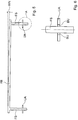
Fig. 3 ist die Vorrichtung VO nochmals in einer Seitenansicht gezeigt. Man erkennt, dass das Führungsmittel FM nicht zentral mittig am Rahmen RA des Formunterteils FU bzw. des Formoberteils FB angeordnet sein muss. Desweiteren istFig. 3 zu entnehmen, dass das Führungsmittel FM einen unteren Abschnitt aufweist, in den ein zylindrischer Führungsstift FS eintauchen kann. Der untere Abschnitt ist dabei als Buchse ausgebildet, wobei der Führungsstift FS innerhalb der Buchse, die eine zylindrische Innenseite aufweist, ein gewisses Spiel aufweist. Der Führungsstift FS wird am Formoberteil FB mittels einer Halterung HA befestigt, wobei der untere Abschnitt des Führungsmittels FM am Formunterteil FU anschraubbar ist. Diese Vorgehensweise ermöglicht eine einfache Nachrüstung bereits bestehender Vorrichtungen VO. - In
Fig. 4 ist die Seitenansicht ausFig. 3 nochmals von der gegenüber liegenden Seite gezeigt. Die Anbringung des Führungsmittels FM wird hierbei identisch zur gegenüber liegenden Seite gewählt, wobei hier auch andere Konfigurationen denkbar sind. Desweiteren ist eine Befestigungsschraube BF gezeigt, die den Führungsstift FS des Führungsmittels FM hält. Demnach ist es möglich, beispielsweise nach längerem Betrieb der Vorrichtung VO einen Führungsstift FS oder mehrere Führungsstifte FS auszuwechseln. - In
Fig. 5 ist in einer schematischen Ansicht nochmals das Verkippen des Formunterteils FU gegen das Formoberteil FB gezeigt. In dieser schematischen Darstellung sind jeweils zwei Führungsstifte FS gezeigt, die wie bereits im Zusammenhang mit denFig. 1 bis 4 beschrieben, außerhalb der Druckstempel DS am Formoberteil FB angebracht sind. Das Formunterteil, das inFig. 5 lediglich als untere Auflage UA dargestellt ist, kann, wie bereits erwähnt, außerhalb des Rahmens RA die Führungsstifte FS aufnehmen. Aufgrund der gewählten Dimensionierung innerhalb der Durchführung der unteren Auflage UA ist somit ein Verkippen des Formunterteils FU gegen das Formoberteil FB möglich, das inFig. 5 schematisch anhand des Winkels WN eingezeichnet ist. Der Winkel WN kann dabei weniger als 2° betragen, wobei insbesondere ein Wert von etwa 1° sich als vorteilhaft herausgestellt hat. Da die Begrenzung des Winkels WN vorteilhafterweise durch die Dimensionierung des Führungsstiftes FS in der Durchführung innerhalb der unteren Auflage UA erreicht wird, wird diese inFig. 5 als Detail A gekennzeichnet, nochmals vergrößert dargestellt. - In
Fig. 6 ist das Detail A in einer Schnittansicht gezeigt, wobei innerhalb der unteren Auflage UA eine Buchse BU angedeutet ist, die mit ihren kreiszylindrischen Innenflächen die kreiszylindrische Außenfläche des Führungsstiftes FS begrenzt. Den Innendurchmesser der Buchse BU sowie den Außendurchmesser des Führungsstiftes FS kann ohne Schwierigkeiten bei bekannter Höhe der Buchse BU sowie den Abständen der beiden Führungsstifte FS zueinander berechnet werden. Um beispielsweise bei einem Abstand von ca. 1,5 m der beiden Führungsstifte FS zueinander eine Verkippung von weniger als 1° zu erreichen, kann der Führungsstift mit einem Außendurchmesser von 40 mm in eine 14 mm hohe Buchse BU eingreifen. Der Innendurchmesser der Buchse BU wird etwa 10 % größer gewählt als der Außendurchmesser des Führungsstiftes FS, um die gewünschte Verkippung von weniger als 1° des Winkels WN zu erreichen. - Die vorstehend und die in den Ansprüchen angegebenen sowie die den Abbildungen entnehmbaren Merkmale sind sowohl einzeln als auch in verschiedener Kombination vorteilhaft realisierbar. Die Erfindung ist nicht auf die beschriebenen Ausführungsbeispiele beschränkt, sondern im Rahmen fachmännischen Könnens in mancherlei Weise abwandelbar.
Claims (10)
- Vorrichtung zur Herstellung von Betonformteilen in einer Formmaschine, die ein Formoberteil mit wenigstens einem Druckstempel zur Übertragung einer Kraft auf wenigstens eine Druckplatte umfasst, wobei die Druckplatte in vertikaler Richtung in eine Öffnung eines Formnestes in einem Formunterteil einführbar ist, wobei das Formunterteil von einem Rahmen umgeben ist, der ein mit dem Formoberteil verbundenes Führungsmittel aufweist, das so ausgebildet ist, dass das Formunterteil gegen das Formoberteil aus der vertikalen Richtung während des Eingreifens der Druckplatten in die Öffnungen des Formnests kippbar ist.
- Vorrichtung nach Anspruch 1, bei der das Führungsmittel auf jeweils zwei gegenüber liegenden Seiten des Rahmens angeordnet ist.
- Vorrichtung nach Anspruch 1 oder 2, bei der das Führungsmittel einen entlang der vertikalen Richtung ausgebildeten länglichen Körper mit zur vertikalen Richtung wenigstens abschnittsweise parallelen Seitenlinien umfasst, der in eine zumindest teilweise korrespondierende Durchführung eingreift.
- Vorrichtung nach Anspruch 3, bei der der längliche Körper mit dem Formoberteil und die Durchführung mit dem Formunterteil verbunden sind.
- Vorrichtung nach Anspruch 4, bei der der längliche Körper und die Durchführung Abmessungen aufweisen, die so gewählt sind, dass ein Maximalwert der Verkippung des Formunterteils gegen das Formoberteil vorgegeben ist.
- Vorrichtung nach einem der Ansprüche 1 bis 5, bei der das Formunterteil gegen das Formoberteil um einen Winkel kippbar ist, der im Bereich von weniger als 2° liegt und insbesondere ungefähr 1° beträgt.
- Vorrichtung nach einem der Ansprüche 1 bis 6, bei der der längliche Körper als kreiszylindrischer Stift ausgeführt ist, der in eine am Rahmen angeordnete mit einer kreiszylindrischen Innenfläche versehene Buchse als Durchführung eingreift.
- Vorrichtung nach Anspruch 7, bei der der Außendurchmesser des kreiszylindrischen Stifts in Abhängigkeit einer Höhe der Buchse entlang der vertikalen Richtung und einem Innendurchmesser der im Rahmen angeordneten Buchse gewählt ist.
- Vorrichtung nach Anspruch 7 oder 8, bei der der Führungsstift und/oder die Buchse austauschbar in dem Führungsmittel befestigt sind.
- Vorrichtung nach einem der Ansprüche 1 bis 9, bei der das Führungsmittel an den Rahmen des Formunterteils seitlich außerhalb des Formnests und außerhalb der Druckstempel seitlich des Formoberteils anschraubbar ist.
Priority Applications (1)
| Application Number | Priority Date | Filing Date | Title |
|---|---|---|---|
| PL16159447.8T PL3075504T5 (pl) | 2015-03-16 | 2016-03-09 | Urządzenie do wytwarzania kształtek betonowych w maszynie formierskiej |
Applications Claiming Priority (1)
| Application Number | Priority Date | Filing Date | Title |
|---|---|---|---|
| DE102015103829.3A DE102015103829A1 (de) | 2015-03-16 | 2015-03-16 | Vorrichtung zur Herstellung von Betonformteilen in einer Formmaschine |
Publications (3)
| Publication Number | Publication Date |
|---|---|
| EP3075504A1 true EP3075504A1 (de) | 2016-10-05 |
| EP3075504B1 EP3075504B1 (de) | 2022-01-05 |
| EP3075504B2 EP3075504B2 (de) | 2026-01-07 |
Family
ID=55650079
Family Applications (1)
| Application Number | Title | Priority Date | Filing Date |
|---|---|---|---|
| EP16159447.8A Active EP3075504B2 (de) | 2015-03-16 | 2016-03-09 | Vorrichtung zur herstellung von betonformteilen in einer formmaschine |
Country Status (9)
| Country | Link |
|---|---|
| US (1) | US9610708B2 (de) |
| EP (1) | EP3075504B2 (de) |
| CA (1) | CA2923914C (de) |
| DE (1) | DE102015103829A1 (de) |
| DK (1) | DK3075504T4 (de) |
| ES (1) | ES2905475T5 (de) |
| FI (1) | FI3075504T4 (de) |
| HU (1) | HUE057943T2 (de) |
| PL (1) | PL3075504T5 (de) |
Families Citing this family (3)
| Publication number | Priority date | Publication date | Assignee | Title |
|---|---|---|---|---|
| CN106596238B (zh) * | 2016-10-19 | 2023-07-21 | 浙江科技学院(浙江中德科技促进中心) | 吻合岩石结构面上下盘的整体成型制作模具 |
| DE102019108574A1 (de) | 2019-04-02 | 2020-10-08 | Kobra Formen Gmbh | Führungseinrichtung in einer Formmaschine und Formmaschine mit einer solchen Führungseinrichtung |
| DE102019135427A1 (de) | 2019-12-20 | 2021-06-24 | Kobra Formen Gmbh | Vorrichtung zur Herstellung von Betonsteinen |
Citations (5)
| Publication number | Priority date | Publication date | Assignee | Title |
|---|---|---|---|---|
| DE3638207A1 (de) | 1986-11-08 | 1988-05-11 | Netter Gmbh | Verfahren zur herstellung von betonfomsteinen und vorrichtung zur durchfuehrung des verfahrens |
| DE19924926C1 (de) | 1999-05-31 | 2000-04-13 | Hubaleck Gmbh U Co Kg | Steinformmaschine mit Steinform für Mauerwerksteine |
| DE102004004188A1 (de) * | 2004-01-28 | 2005-10-06 | Manfred Lebherz | Beton-Formstein-Fertigungseinrichtung |
| DE102005048930A1 (de) | 2004-11-12 | 2006-05-18 | Rampf Formen Gmbh | Steinform, insbesondere zur Herstellung von Betonsteinen und Steinformmaschine mit Steinform |
| US20060197259A1 (en) * | 2005-03-01 | 2006-09-07 | Rampf Molds Industries, Inc. | Apparatus and method for a mold alignment system |
Family Cites Families (3)
| Publication number | Priority date | Publication date | Assignee | Title |
|---|---|---|---|---|
| US2479350A (en) * | 1947-10-03 | 1949-08-16 | Jr John C Haggart | Apparatus for molding reflector devices |
| US4941813A (en) * | 1988-12-13 | 1990-07-17 | Grubb Jr Lloyd T | Mold guidance system for block making machinery |
| DE102008017964A1 (de) | 2008-04-08 | 2009-10-15 | Rampf Formen Gmbh | Anlage zur Herstellung von Formsteinen |
-
2015
- 2015-03-16 DE DE102015103829.3A patent/DE102015103829A1/de not_active Withdrawn
-
2016
- 2016-03-09 EP EP16159447.8A patent/EP3075504B2/de active Active
- 2016-03-09 PL PL16159447.8T patent/PL3075504T5/pl unknown
- 2016-03-09 HU HUE16159447A patent/HUE057943T2/hu unknown
- 2016-03-09 DK DK16159447.8T patent/DK3075504T4/da active
- 2016-03-09 ES ES16159447T patent/ES2905475T5/es active Active
- 2016-03-09 FI FIEP16159447.8T patent/FI3075504T4/fi active
- 2016-03-15 US US15/070,209 patent/US9610708B2/en active Active
- 2016-03-16 CA CA2923914A patent/CA2923914C/en active Active
Patent Citations (5)
| Publication number | Priority date | Publication date | Assignee | Title |
|---|---|---|---|---|
| DE3638207A1 (de) | 1986-11-08 | 1988-05-11 | Netter Gmbh | Verfahren zur herstellung von betonfomsteinen und vorrichtung zur durchfuehrung des verfahrens |
| DE19924926C1 (de) | 1999-05-31 | 2000-04-13 | Hubaleck Gmbh U Co Kg | Steinformmaschine mit Steinform für Mauerwerksteine |
| DE102004004188A1 (de) * | 2004-01-28 | 2005-10-06 | Manfred Lebherz | Beton-Formstein-Fertigungseinrichtung |
| DE102005048930A1 (de) | 2004-11-12 | 2006-05-18 | Rampf Formen Gmbh | Steinform, insbesondere zur Herstellung von Betonsteinen und Steinformmaschine mit Steinform |
| US20060197259A1 (en) * | 2005-03-01 | 2006-09-07 | Rampf Molds Industries, Inc. | Apparatus and method for a mold alignment system |
Also Published As
| Publication number | Publication date |
|---|---|
| EP3075504B1 (de) | 2022-01-05 |
| PL3075504T3 (pl) | 2022-03-21 |
| CA2923914C (en) | 2018-05-29 |
| FI3075504T4 (fi) | 2026-04-08 |
| HUE057943T2 (hu) | 2022-06-28 |
| ES2905475T5 (en) | 2026-05-13 |
| DK3075504T4 (da) | 2026-03-30 |
| US20160271828A1 (en) | 2016-09-22 |
| ES2905475T3 (es) | 2022-04-08 |
| EP3075504B2 (de) | 2026-01-07 |
| PL3075504T5 (pl) | 2026-04-20 |
| CA2923914A1 (en) | 2016-09-16 |
| DE102015103829A1 (de) | 2016-09-22 |
| DK3075504T3 (da) | 2022-02-07 |
| US9610708B2 (en) | 2017-04-04 |
Similar Documents
| Publication | Publication Date | Title |
|---|---|---|
| EP4076881B1 (de) | Vorrichtung zur herstellung von betonsteinen | |
| EP3253567B1 (de) | Pulverpresse mit kegeligem unterbau | |
| EP0730936B2 (de) | Rüttelform | |
| EP3003601B1 (de) | Speisereinsatz, formelement für den speisereinsatz und verfahren zum giessen von metall unter verwendung derselben | |
| EP2982458B1 (de) | Anordnung zur verwendung beim herstellen einer teilbaren giessform | |
| WO2011127925A1 (de) | Vorrichtung und verfahren zur herstellung von betonformsteinen sowie form hierfür | |
| EP3075504B1 (de) | Vorrichtung zur herstellung von betonformteilen in einer formmaschine | |
| EP3075505B1 (de) | Vorrichtung zur herstellung von betonformteilen | |
| DE60302471T2 (de) | Ausrichtungsmittel für eine spritzgiessvorrichtung | |
| DE102005044759B4 (de) | Vorrichtung zum Herstellen eines Formteils | |
| WO2019002600A1 (de) | Ebenenplatte eines pressenwerkzeugs | |
| EP2718071A1 (de) | Steinformmaschine und verfahren zur höhenverstellung einer steinformmaschine | |
| DE102007019388A1 (de) | Form zur Herstellung von Betonformsteinen und Verfahren zu deren Herstellung | |
| DE102015206587A1 (de) | Verfahren zur Herstellung einer Baugruppe | |
| DE102005048930B4 (de) | Form zur Herstellung von Betonsteinen und Steinformmaschine mit Form | |
| DE202011108698U1 (de) | Vorrichtung zur Erzeugung einer abgießbaren Markierung an einem Kern oder an einer Gießform für den Abguss eines Gießteiles | |
| DE102017102323A1 (de) | Vorrichtung zur Herstellung von Betonformteilen | |
| EP3718718B1 (de) | Führungseinrichtung in einer formmaschine und formmaschine mit einer solchen führungseinrichtung | |
| EP4292789A1 (de) | Druckgiessform | |
| EP2718070B1 (de) | Steinformmaschine mit lineargeführtem tragelement | |
| WO2019048688A1 (de) | Vorrichtung zur herstellung von betonformteilen | |
| DE102005058403A1 (de) | Vorrichtung zur Herstellung von Betonformsteinen und Formensystem | |
| DE202018104816U1 (de) | Formwechselsystem und Formungsmaschine | |
| DE102012022210A1 (de) | Verfahren zur Herstellung einer Vorrichtung mit mindestens einer Mikrobohrung und Vorrichtung | |
| EP3466637A1 (de) | Werkzeug-aufspannplatte für eine kunststoffverarbeitungsmaschine, insbesondere für eine spritzgiessmaschine |
Legal Events
| Date | Code | Title | Description |
|---|---|---|---|
| PUAI | Public reference made under article 153(3) epc to a published international application that has entered the european phase |
Free format text: ORIGINAL CODE: 0009012 |
|
| AK | Designated contracting states |
Kind code of ref document: A1 Designated state(s): AL AT BE BG CH CY CZ DE DK EE ES FI FR GB GR HR HU IE IS IT LI LT LU LV MC MK MT NL NO PL PT RO RS SE SI SK SM TR |
|
| AX | Request for extension of the european patent |
Extension state: BA ME |
|
| STAA | Information on the status of an ep patent application or granted ep patent |
Free format text: STATUS: REQUEST FOR EXAMINATION WAS MADE |
|
| 17P | Request for examination filed |
Effective date: 20170405 |
|
| RBV | Designated contracting states (corrected) |
Designated state(s): AL AT BE BG CH CY CZ DE DK EE ES FI FR GB GR HR HU IE IS IT LI LT LU LV MC MK MT NL NO PL PT RO RS SE SI SK SM TR |
|
| STAA | Information on the status of an ep patent application or granted ep patent |
Free format text: STATUS: EXAMINATION IS IN PROGRESS |
|
| 17Q | First examination report despatched |
Effective date: 20181023 |
|
| GRAP | Despatch of communication of intention to grant a patent |
Free format text: ORIGINAL CODE: EPIDOSNIGR1 |
|
| STAA | Information on the status of an ep patent application or granted ep patent |
Free format text: STATUS: GRANT OF PATENT IS INTENDED |
|
| INTG | Intention to grant announced |
Effective date: 20210916 |
|
| GRAS | Grant fee paid |
Free format text: ORIGINAL CODE: EPIDOSNIGR3 |
|
| GRAA | (expected) grant |
Free format text: ORIGINAL CODE: 0009210 |
|
| STAA | Information on the status of an ep patent application or granted ep patent |
Free format text: STATUS: THE PATENT HAS BEEN GRANTED |
|
| AK | Designated contracting states |
Kind code of ref document: B1 Designated state(s): AL AT BE BG CH CY CZ DE DK EE ES FI FR GB GR HR HU IE IS IT LI LT LU LV MC MK MT NL NO PL PT RO RS SE SI SK SM TR |
|
| REG | Reference to a national code |
Ref country code: GB Ref legal event code: FG4D Free format text: NOT ENGLISH |
|
| REG | Reference to a national code |
Ref country code: CH Ref legal event code: EP |
|
| REG | Reference to a national code |
Ref country code: AT Ref legal event code: REF Ref document number: 1460124 Country of ref document: AT Kind code of ref document: T Effective date: 20220115 |
|
| REG | Reference to a national code |
Ref country code: DE Ref legal event code: R096 Ref document number: 502016014336 Country of ref document: DE |
|
| REG | Reference to a national code |
Ref country code: FI Ref legal event code: FGE Ref country code: IE Ref legal event code: FG4D Free format text: LANGUAGE OF EP DOCUMENT: GERMAN |
|
| REG | Reference to a national code |
Ref country code: DK Ref legal event code: T3 Effective date: 20220131 |
|
| REG | Reference to a national code |
Ref country code: NL Ref legal event code: FP |
|
| REG | Reference to a national code |
Ref country code: SE Ref legal event code: TRGR |
|
| REG | Reference to a national code |
Ref country code: NO Ref legal event code: T2 Effective date: 20220105 |
|
| REG | Reference to a national code |
Ref country code: ES Ref legal event code: FG2A Ref document number: 2905475 Country of ref document: ES Kind code of ref document: T3 Effective date: 20220408 |
|
| REG | Reference to a national code |
Ref country code: LT Ref legal event code: MG9D |
|
| REG | Reference to a national code |
Ref country code: HU Ref legal event code: AG4A Ref document number: E057943 Country of ref document: HU |
|
| PG25 | Lapsed in a contracting state [announced via postgrant information from national office to epo] |
Ref country code: RS Free format text: LAPSE BECAUSE OF FAILURE TO SUBMIT A TRANSLATION OF THE DESCRIPTION OR TO PAY THE FEE WITHIN THE PRESCRIBED TIME-LIMIT Effective date: 20220105 Ref country code: PT Free format text: LAPSE BECAUSE OF FAILURE TO SUBMIT A TRANSLATION OF THE DESCRIPTION OR TO PAY THE FEE WITHIN THE PRESCRIBED TIME-LIMIT Effective date: 20220505 Ref country code: LT Free format text: LAPSE BECAUSE OF FAILURE TO SUBMIT A TRANSLATION OF THE DESCRIPTION OR TO PAY THE FEE WITHIN THE PRESCRIBED TIME-LIMIT Effective date: 20220105 Ref country code: HR Free format text: LAPSE BECAUSE OF FAILURE TO SUBMIT A TRANSLATION OF THE DESCRIPTION OR TO PAY THE FEE WITHIN THE PRESCRIBED TIME-LIMIT Effective date: 20220105 Ref country code: BG Free format text: LAPSE BECAUSE OF FAILURE TO SUBMIT A TRANSLATION OF THE DESCRIPTION OR TO PAY THE FEE WITHIN THE PRESCRIBED TIME-LIMIT Effective date: 20220405 |
|
| PG25 | Lapsed in a contracting state [announced via postgrant information from national office to epo] |
Ref country code: LV Free format text: LAPSE BECAUSE OF FAILURE TO SUBMIT A TRANSLATION OF THE DESCRIPTION OR TO PAY THE FEE WITHIN THE PRESCRIBED TIME-LIMIT Effective date: 20220105 Ref country code: GR Free format text: LAPSE BECAUSE OF FAILURE TO SUBMIT A TRANSLATION OF THE DESCRIPTION OR TO PAY THE FEE WITHIN THE PRESCRIBED TIME-LIMIT Effective date: 20220406 |
|
| PG25 | Lapsed in a contracting state [announced via postgrant information from national office to epo] |
Ref country code: IS Free format text: LAPSE BECAUSE OF FAILURE TO SUBMIT A TRANSLATION OF THE DESCRIPTION OR TO PAY THE FEE WITHIN THE PRESCRIBED TIME-LIMIT Effective date: 20220505 |
|
| REG | Reference to a national code |
Ref country code: DE Ref legal event code: R026 Ref document number: 502016014336 Country of ref document: DE |
|
| PLBI | Opposition filed |
Free format text: ORIGINAL CODE: 0009260 |
|
| PLAX | Notice of opposition and request to file observation + time limit sent |
Free format text: ORIGINAL CODE: EPIDOSNOBS2 |
|
| PG25 | Lapsed in a contracting state [announced via postgrant information from national office to epo] |
Ref country code: SM Free format text: LAPSE BECAUSE OF FAILURE TO SUBMIT A TRANSLATION OF THE DESCRIPTION OR TO PAY THE FEE WITHIN THE PRESCRIBED TIME-LIMIT Effective date: 20220105 Ref country code: SK Free format text: LAPSE BECAUSE OF FAILURE TO SUBMIT A TRANSLATION OF THE DESCRIPTION OR TO PAY THE FEE WITHIN THE PRESCRIBED TIME-LIMIT Effective date: 20220105 Ref country code: RO Free format text: LAPSE BECAUSE OF FAILURE TO SUBMIT A TRANSLATION OF THE DESCRIPTION OR TO PAY THE FEE WITHIN THE PRESCRIBED TIME-LIMIT Effective date: 20220105 Ref country code: MC Free format text: LAPSE BECAUSE OF FAILURE TO SUBMIT A TRANSLATION OF THE DESCRIPTION OR TO PAY THE FEE WITHIN THE PRESCRIBED TIME-LIMIT Effective date: 20220105 Ref country code: EE Free format text: LAPSE BECAUSE OF FAILURE TO SUBMIT A TRANSLATION OF THE DESCRIPTION OR TO PAY THE FEE WITHIN THE PRESCRIBED TIME-LIMIT Effective date: 20220105 |
|
| REG | Reference to a national code |
Ref country code: CH Ref legal event code: PL |
|
| 26 | Opposition filed |
Opponent name: RAMPF FORMEN GMBH Effective date: 20221005 |
|
| PG25 | Lapsed in a contracting state [announced via postgrant information from national office to epo] |
Ref country code: AL Free format text: LAPSE BECAUSE OF FAILURE TO SUBMIT A TRANSLATION OF THE DESCRIPTION OR TO PAY THE FEE WITHIN THE PRESCRIBED TIME-LIMIT Effective date: 20220105 |
|
| GBPC | Gb: european patent ceased through non-payment of renewal fee |
Effective date: 20220405 |
|
| PG25 | Lapsed in a contracting state [announced via postgrant information from national office to epo] |
Ref country code: LI Free format text: LAPSE BECAUSE OF NON-PAYMENT OF DUE FEES Effective date: 20220331 Ref country code: IE Free format text: LAPSE BECAUSE OF NON-PAYMENT OF DUE FEES Effective date: 20220309 Ref country code: GB Free format text: LAPSE BECAUSE OF NON-PAYMENT OF DUE FEES Effective date: 20220405 Ref country code: CH Free format text: LAPSE BECAUSE OF NON-PAYMENT OF DUE FEES Effective date: 20220331 |
|
| PG25 | Lapsed in a contracting state [announced via postgrant information from national office to epo] |
Ref country code: SI Free format text: LAPSE BECAUSE OF FAILURE TO SUBMIT A TRANSLATION OF THE DESCRIPTION OR TO PAY THE FEE WITHIN THE PRESCRIBED TIME-LIMIT Effective date: 20220105 |
|
| PLBB | Reply of patent proprietor to notice(s) of opposition received |
Free format text: ORIGINAL CODE: EPIDOSNOBS3 |
|
| PG25 | Lapsed in a contracting state [announced via postgrant information from national office to epo] |
Ref country code: IT Free format text: LAPSE BECAUSE OF FAILURE TO SUBMIT A TRANSLATION OF THE DESCRIPTION OR TO PAY THE FEE WITHIN THE PRESCRIBED TIME-LIMIT Effective date: 20220105 |
|
| PG25 | Lapsed in a contracting state [announced via postgrant information from national office to epo] |
Ref country code: MK Free format text: LAPSE BECAUSE OF FAILURE TO SUBMIT A TRANSLATION OF THE DESCRIPTION OR TO PAY THE FEE WITHIN THE PRESCRIBED TIME-LIMIT Effective date: 20220105 Ref country code: CY Free format text: LAPSE BECAUSE OF FAILURE TO SUBMIT A TRANSLATION OF THE DESCRIPTION OR TO PAY THE FEE WITHIN THE PRESCRIBED TIME-LIMIT Effective date: 20220105 |
|
| PG25 | Lapsed in a contracting state [announced via postgrant information from national office to epo] |
Ref country code: MT Free format text: LAPSE BECAUSE OF FAILURE TO SUBMIT A TRANSLATION OF THE DESCRIPTION OR TO PAY THE FEE WITHIN THE PRESCRIBED TIME-LIMIT Effective date: 20220105 |
|
| PUAH | Patent maintained in amended form |
Free format text: ORIGINAL CODE: 0009272 |
|
| STAA | Information on the status of an ep patent application or granted ep patent |
Free format text: STATUS: PATENT MAINTAINED AS AMENDED |
|
| REG | Reference to a national code |
Ref country code: CH Ref legal event code: M12 Free format text: ST27 STATUS EVENT CODE: U-0-0-M10-M12 (AS PROVIDED BY THE NATIONAL OFFICE) Effective date: 20251210 |
|
| PG25 | Lapsed in a contracting state [announced via postgrant information from national office to epo] |
Ref country code: TR Free format text: LAPSE BECAUSE OF FAILURE TO SUBMIT A TRANSLATION OF THE DESCRIPTION OR TO PAY THE FEE WITHIN THE PRESCRIBED TIME-LIMIT Effective date: 20220105 |
|
| 27A | Patent maintained in amended form |
Effective date: 20260107 |
|
| AK | Designated contracting states |
Kind code of ref document: B2 Designated state(s): AL AT BE BG CH CY CZ DE DK EE ES FI FR GB GR HR HU IE IS IT LI LT LU LV MC MK MT NL NO PL PT RO RS SE SI SK SM TR |
|
| REG | Reference to a national code |
Ref country code: DE Ref legal event code: R102 Ref document number: 502016014336 Country of ref document: DE |
|
| REG | Reference to a national code |
Ref country code: DK Ref legal event code: T4 Effective date: 20260327 |
|
| PGFP | Annual fee paid to national office [announced via postgrant information from national office to epo] |
Ref country code: SE Payment date: 20260323 Year of fee payment: 11 |
|
| REG | Reference to a national code |
Ref country code: NL Ref legal event code: FP |
|
| PGFP | Annual fee paid to national office [announced via postgrant information from national office to epo] |
Ref country code: DE Payment date: 20260331 Year of fee payment: 11 Ref country code: DK Payment date: 20260323 Year of fee payment: 11 Ref country code: NO Payment date: 20260320 Year of fee payment: 11 |
|
| PGFP | Annual fee paid to national office [announced via postgrant information from national office to epo] |
Ref country code: AT Payment date: 20260319 Year of fee payment: 11 |
|
| PGFP | Annual fee paid to national office [announced via postgrant information from national office to epo] |
Ref country code: FI Payment date: 20260320 Year of fee payment: 11 Ref country code: LU Payment date: 20260320 Year of fee payment: 11 Ref country code: BE Payment date: 20260323 Year of fee payment: 11 |
|
| PGFP | Annual fee paid to national office [announced via postgrant information from national office to epo] |
Ref country code: HU Payment date: 20260306 Year of fee payment: 11 Ref country code: NL Payment date: 20260323 Year of fee payment: 11 |
|
| PGFP | Annual fee paid to national office [announced via postgrant information from national office to epo] |
Ref country code: FR Payment date: 20260325 Year of fee payment: 11 |
|
| PGFP | Annual fee paid to national office [announced via postgrant information from national office to epo] |
Ref country code: CZ Payment date: 20260224 Year of fee payment: 11 |
|
| REG | Reference to a national code |
Ref country code: ES Ref legal event code: DC2A Ref document number: 2905475 Country of ref document: ES Kind code of ref document: T5 Effective date: 20260513 |
|
| PGFP | Annual fee paid to national office [announced via postgrant information from national office to epo] |
Ref country code: ES Payment date: 20260420 Year of fee payment: 11 |
|
| PGFP | Annual fee paid to national office [announced via postgrant information from national office to epo] |
Ref country code: PL Payment date: 20260227 Year of fee payment: 11 |