EP3075421A2 - Rekonfigurierbare speichervorrichtung für übungseinrichtung - Google Patents
Rekonfigurierbare speichervorrichtung für übungseinrichtung Download PDFInfo
- Publication number
- EP3075421A2 EP3075421A2 EP16159463.5A EP16159463A EP3075421A2 EP 3075421 A2 EP3075421 A2 EP 3075421A2 EP 16159463 A EP16159463 A EP 16159463A EP 3075421 A2 EP3075421 A2 EP 3075421A2
- Authority
- EP
- European Patent Office
- Prior art keywords
- shelf
- storage apparatus
- stop members
- connection
- spine
- Prior art date
- Legal status (The legal status is an assumption and is not a legal conclusion. Google has not performed a legal analysis and makes no representation as to the accuracy of the status listed.)
- Granted
Links
Images
Classifications
-
- A—HUMAN NECESSITIES
- A63—SPORTS; GAMES; AMUSEMENTS
- A63B—APPARATUS FOR PHYSICAL TRAINING, GYMNASTICS, SWIMMING, CLIMBING, OR FENCING; BALL GAMES; TRAINING EQUIPMENT
- A63B71/00—Games or sports accessories not covered in groups A63B1/00 - A63B69/00
- A63B71/0036—Accessories for stowing, putting away or transporting exercise apparatus or sports equipment
-
- A—HUMAN NECESSITIES
- A47—FURNITURE; DOMESTIC ARTICLES OR APPLIANCES; COFFEE MILLS; SPICE MILLS; SUCTION CLEANERS IN GENERAL
- A47B—TABLES; DESKS; OFFICE FURNITURE; CABINETS; DRAWERS; GENERAL DETAILS OF FURNITURE
- A47B57/00—Cabinets, racks or shelf units, characterised by features for adjusting shelves or partitions
- A47B57/58—Cabinets, racks or shelf units, characterised by features for adjusting shelves or partitions with means for adjusting partitions horizontally
- A47B57/588—Cabinets, racks or shelf units, characterised by features for adjusting shelves or partitions with means for adjusting partitions horizontally by means of shelf bottoms with apertures co-operating with tongues or pins
-
- A—HUMAN NECESSITIES
- A47—FURNITURE; DOMESTIC ARTICLES OR APPLIANCES; COFFEE MILLS; SPICE MILLS; SUCTION CLEANERS IN GENERAL
- A47B—TABLES; DESKS; OFFICE FURNITURE; CABINETS; DRAWERS; GENERAL DETAILS OF FURNITURE
- A47B81/00—Cabinets or racks specially adapted for other particular purposes, e.g. for storing guns or skis
- A47B81/007—Racks for cylindrical or barrel-like objects, e.g. casks, rolls
-
- A—HUMAN NECESSITIES
- A47—FURNITURE; DOMESTIC ARTICLES OR APPLIANCES; COFFEE MILLS; SPICE MILLS; SUCTION CLEANERS IN GENERAL
- A47B—TABLES; DESKS; OFFICE FURNITURE; CABINETS; DRAWERS; GENERAL DETAILS OF FURNITURE
- A47B96/00—Details of cabinets, racks or shelf units not covered by a single one of groups A47B43/00 - A47B95/00; General details of furniture
- A47B96/02—Shelves
- A47B96/025—Shelves with moving elements, e.g. movable extensions or link elements
-
- A—HUMAN NECESSITIES
- A47—FURNITURE; DOMESTIC ARTICLES OR APPLIANCES; COFFEE MILLS; SPICE MILLS; SUCTION CLEANERS IN GENERAL
- A47F—SPECIAL FURNITURE, FITTINGS, OR ACCESSORIES FOR SHOPS, STOREHOUSES, BARS, RESTAURANTS OR THE LIKE; PAYING COUNTERS
- A47F5/00—Show stands, hangers, or shelves characterised by their constructional features
- A47F5/0043—Show shelves
- A47F5/005—Partitions therefore
-
- A—HUMAN NECESSITIES
- A63—SPORTS; GAMES; AMUSEMENTS
- A63B—APPARATUS FOR PHYSICAL TRAINING, GYMNASTICS, SWIMMING, CLIMBING, OR FENCING; BALL GAMES; TRAINING EQUIPMENT
- A63B21/00—Exercising apparatus for developing or strengthening the muscles or joints of the body by working against a counterforce, with or without measuring devices
- A63B21/06—User-manipulated weights
- A63B21/078—Devices for bench press exercises, e.g. supports, guiding means
-
- A—HUMAN NECESSITIES
- A47—FURNITURE; DOMESTIC ARTICLES OR APPLIANCES; COFFEE MILLS; SPICE MILLS; SUCTION CLEANERS IN GENERAL
- A47B—TABLES; DESKS; OFFICE FURNITURE; CABINETS; DRAWERS; GENERAL DETAILS OF FURNITURE
- A47B57/00—Cabinets, racks or shelf units, characterised by features for adjusting shelves or partitions
- A47B57/06—Cabinets, racks or shelf units, characterised by features for adjusting shelves or partitions with means for adjusting the height of the shelves
- A47B57/20—Cabinets, racks or shelf units, characterised by features for adjusting shelves or partitions with means for adjusting the height of the shelves consisting of tongues, pins or similar projecting means coacting with openings
-
- A—HUMAN NECESSITIES
- A47—FURNITURE; DOMESTIC ARTICLES OR APPLIANCES; COFFEE MILLS; SPICE MILLS; SUCTION CLEANERS IN GENERAL
- A47F—SPECIAL FURNITURE, FITTINGS, OR ACCESSORIES FOR SHOPS, STOREHOUSES, BARS, RESTAURANTS OR THE LIKE; PAYING COUNTERS
- A47F5/00—Show stands, hangers, or shelves characterised by their constructional features
- A47F5/10—Adjustable or foldable or dismountable display stands
- A47F5/101—Display racks with slotted uprights
-
- A—HUMAN NECESSITIES
- A63—SPORTS; GAMES; AMUSEMENTS
- A63B—APPARATUS FOR PHYSICAL TRAINING, GYMNASTICS, SWIMMING, CLIMBING, OR FENCING; BALL GAMES; TRAINING EQUIPMENT
- A63B21/00—Exercising apparatus for developing or strengthening the muscles or joints of the body by working against a counterforce, with or without measuring devices
- A63B21/06—User-manipulated weights
- A63B21/072—Dumb-bells, bar-bells or the like, e.g. weight discs having an integral peripheral handle
- A63B21/0726—Dumb bells, i.e. with a central bar to be held by a single hand, and with weights at the ends
-
- A—HUMAN NECESSITIES
- A63—SPORTS; GAMES; AMUSEMENTS
- A63B—APPARATUS FOR PHYSICAL TRAINING, GYMNASTICS, SWIMMING, CLIMBING, OR FENCING; BALL GAMES; TRAINING EQUIPMENT
- A63B2225/00—Miscellaneous features of sport apparatus, devices or equipment
- A63B2225/09—Adjustable dimensions
Definitions
- the present invention relates to an exercise equipment storage apparatus, and in particular a reconfigurable shelving unit for weighted exercise equipment.
- storage is typically individually tailored to specific equipment, with dedicated storage being required for each range of equipment.
- storage is in the form of shelving racks.
- a retaining element is required to hold, cradle or otherwise restrain the equipment, which differ in size and orientation from equipment to equipment. It is therefore not generally possible to safely store more than one type of equipment on a given storage apparatus.
- the requirement to provide a wide range of different storage solutions results in storage inefficiency and limits the variety of equipment that may be provided.
- a further disadvantage, particularly for smaller gyms that require equipment in more limited numbers, is that the number of units of each type of equipment may be significantly less than the number of units which the dedicated storage unit is configured to store. Therefore, the storage unit represents an inefficient use of space and cost.
- the plurality of stop members are retaining elements and preferably cooperate in pairs to form a channel defining the at least one storage zone.
- a single stop member may cooperate with more than other stop member simultaneously in a paired arrangement.
- a stop member may have stop formations on two sides, with each side pairing with a different stop member.
- a holding channel is sufficient to retain a piece of exercise equipment, and the channels may cooperate with retaining walls, lips or the like at the front and or rear edges of the shelves to retain the equipment.
- the stop members may comprise an elongate body having a stop surface extending along the length of the body.
- the shelves are preferably substantially square and the length of the stop members is preferably substantially equal to the length if the sides of the shelves such that in either the lengthwise or transverse orientation the stop members extend substantially across the entire depth or width of the shelf.
- the stop surface is inclined transversely to the length of the body to define a wedge formation.
- the wedge formation advantageously enables the stops members to cradle equipment having a rounded lower surface with the wedging action preventing rolling of the equipment in at least the transverse direction.
- the stop members preferably have a vertical rear wall extending along the length of the body on the opposing side to inclined wedge surface. This enables the stop members to be
- the pairs of stop members are preferably arranged parallel to each other with the inclined surfaces facing towards each other such that the storage zones have a substantially convex configuration in the transverse direction relative to the length of the stop members, thereby defining a substantially convex configuration.
- Each shelf preferably includes a plurality of connection points for securing the stop members to the shelf, the connection points being arranged to define a plurality of connection locations with the stop members being reconfigurable by selective securement to different connection locations selected from the plurality of connection locations.
- Each shelf preferably includes a front edge and an orthogonal array of connection points configured to enable the stop members to be secured to the shelf in a parallel arrangement to each other in which the stop members arranged parallel or transverse to the front edge of the shelf.
- the orthogonal array ensures that the stop members are only able to be secured to the shelf one of a transverse or longitudinal arrangement. Longitudinal is used here to refer to the axis defined front to back of the shelf.
- the plurality of connection points may comprise apertures extending through the shelf for receiving a corresponding connection member.
- the corresponding connection members may be spigots or lugs extending from the stop members, snap fit connections or threaded connectors provided through the shelf from the underside.
- the corresponding connection member is preferably a threaded fastener
- the stop members may include a plurality of threaded bores having a spacing corresponding to the spacing of the apertures of the shelf such that the threaded bores may be aligned with a selected plurality of connection apertures to receive a corresponding plurality of fasteners extending therethrough.
- the support structure preferably comprises an upright spine member and a base member, and wherein a plurality of shelves is secured to the spine.
- the use of a spine enables the shelves to be supported using only a single support member thereby reducing material, parts and cost, as well as maximising access to the shelves with the spine being located at the rear of the shelves with full access to the front and sides, and providing an aesthetically pleasing design with the shelves having a floating appearance.
- a plurality of connection points are preferably provided along the height of the spine and the plurality of shelves are removably connectable to the plurality of the connection points to enable the height and/or relative spacing of the shelves to be selectively varied. As such equipment of varying heights may be accommodated.
- the spine preferably includes a front face and side walls, with the connection points being formed in the side walls, and wherein each shelf comprises a pair of spaced connection brackets extending from the lower surface configured to locate either side of the spine adjacent the side walls to connect the shelf to the spine.
- the shelf also preferably includes a retaining wall, lip or ridge at the front and/or rear edges.
- connection brackets preferably each include a transversely facing connection plate extending downwardly from the lower surface of the shelf having a vertical rear edge and an angled forward edge with the connection plate tapering upwardly in the forward direction towards the lower surface of the shelf.
- the brackets are secured via connectors inserted through the brackets transversely into the side walls of the spine.
- connection brackets may each include a flange plate extending downwardly from the rear edge of the shelf, a forwardly extending angular reinforcement plate connecting the base of the flange plate to the lower surface of the shelf, with the transversely facing connection plate being secured to the flange plate and the angular reinforcement member.
- the upper surface of the base is preferably provided with a plurality of connection points corresponding to the connection points of the shelves to enable the stop members to be secured to the base to provide one or more additional storage zones, thereby maximising the storage efficiency of the apparatus.
- the spine preferably includes a forwardly angled lower section that secures to the base forwardly of the upper section and the base is arranged such that the rear edge of the base is aligned with the rear face of the spine. This ensures that there is a part of the base that extends rearwardly of the connection with the spine for maximum stability, while also ensuring that the apparatus may be placed in flush abutment with a wall with the spine flush with said wall, thereby optimising the use of space.
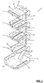
- the shelving assembly 1 comprises a plurality of shelves 2 supported on a support frame 4 having a base 6.
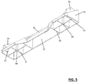
- the support frame 4 comprises a vertical spine member 8 that is preferably formed from rectangular hollow section steel or aluminium.
- the spine 8 includes an upright and preferably substantially vertical main support section 10 and a lower section 12 that is inclined forwardly.
- the spine 8 includes a front facing wall 14, side walls 16 and a rear facing wall 18.
- the front wall 14 is forwardly facing towards the user, and towards the front leading edge of the shelves 2.
- the terms 'forwardly' and 'rearwardly' are relative and are used to refer to a direction towards or away from the leading edge of the shelves and the term 'sideways' refers to a direction transverse to the forward and rearward direction.
- the term 'upwardly' and 'vertically' are relative to the base 6 and refer to a vertical axis perpendicular to the planar upper face of the base 6.
- the lower end 12 of the spine 8 is angled forwardly at an elbow 20 located approximately a fifth of the way along the height of the spine 8.
- the lower section 12 secures to the base 6 at a connection point 24 which has a forward location relative to the main support section 10.
- the base 6 forms a foot for supporting the spine 8 and shelves 2 such that the support assembly 1 is free standing.
- the forwardly inclined arrangement of the lower section 12 of the spine 8 allows a rear portion 22 of the base 6 to extend rearwardly of the connection point 24 with the lower section 12 such that the rear edge 26 of the base 6 is aligned with the rear face 18 of the spine 8. This enables the support assembly 1 to be located flush against a wall with the spine 8 substantially abutting the wall without interference from the base 6.
- the base 6 comprises a planar support plate which preferably extends forwardly at its front edge 28 a greater distance than the front edge of the shelves 2 to maximise stability.
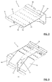
- each shelf 2 includes a ridge 30 along the front edge 32 defining a forward retaining wall.
- the ridge 30 is formed by a v-shaped fold including an inclined surface 34 forming a wedge arrangement on the inner side of the ridge 30 and a vertical flange section 36 defining a flat front facing wall to the shelf.
- a rearwardly inclined wall 42 is also formed to provide a wedge arrangement at the rear edge.
- the front wedge 34 and rear wedge 42 combine to define a concave profile across the shelf 2 along the longitudinal axis defined front to back of the shelf 2.
- a flat section 44 is provided rearwardly of the wedge 42, and a vertical flange section 46 extends vertically downwards at the rear edge of the shelf 2.
- An array of apertures 43 is formed through the main planar section 45 of the shelf 2.
- the apertures 43 are arranged in an orthogonal array with rows extending transversely and longitudinally across the plate. In the embodiment shown in Figure 2 , four transversely extending rows are provided that are evenly spaced in the longitudinal direction. The apertures 43 along these rows also form longitudinally extending rows. Nine apertures are provided across the shelf 2 in the transverse direction such that nine longitudinal rows are defined.
- a channel 48 is defined midway along the rear flange plate 46, with a corresponding cut away 50 being formed in the flat section 44.
- the channel 48 has a width corresponding to the width of the spine 8 with the spine 8 being received in the channel 48 to secure the shelf 2 to the spine 8.
- Either side of the channel 48 are provide longitudinally extending connection plates 52 having a plurality of apertures 54 arranged vertically adjacent the rear edge of the plates 52.
- the size and spacing of the apertures 42 corresponds to a plurality of connection apertures 56 formed along the side walls of the spine 8.
- the apertures 54 of the shelf 2 are aligned with the apertures 56 of the spine 8 and threaded fasteners or any other suitable connection means are passed through the aligned apertures to secure the shelf 2 to the spine 8 at a selected and variable height.
- the apertures 56 of the spine may include an inner thread formed by any suitable means to enable a threaded fastener to be screwed directly into the spine 8.
- the connection plates 52 taper upwardly in the forward direction and provide bracing for the shelf in connection with rear flange plate 46. Forwardly extending upwardly inclined plates 58 extend from the flange plate to the shelf 2 to provide further support, with the inclined plates being connected to the connection plates 52.
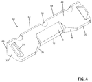
- a stop member 60 comprises an elongate body 62 having an inclined stop surface 64 extending along its length.
- the stop member 60 includes a substantially vertical rear wall 66, an upper edge 68, a front edge 70 and end walls 72.
- the stop surface 64 is inclined downwardly from the upper edge 68 to the front edge 70 in the transverse direction relative to the length of the body 62, such that when viewed from the end the stop member 60 has a substantially right angled triangular cross sectional shape providing the stop member 60 with a wedged configuration.
- the stop surface 64 includes a textured grip surface having an integrally moulded raised waveform pattern which increases the friction coefficient of the surface, thereby improving grip.
- a plurality of scalloped sections 74 are formed along the upper edge 68 having a substantially semicircular shape to allow these sections to cradle a cylindrical bar such as a weight bar or a cylindrical handle or other component of an exercise device when supported on the upper edge 68 of two or more stop members 60.
- a recess 76 is formed centrally along the stop surface 64 and front edge 70 that enables the wedged stop member 60 to more effectively cradle a spherical exercise apparatus such as a medicine ball.
- the recess 76 includes inwardly inclined front edge sections 78 and a section of the stop surface that is inclined downwardly at a greater angle than the rest of the surface.
- the longitudinal stops 79 are provided proximate either end of the stop surface 64.
- the longitudinal stops 79 are preferably rubber or plastic blocks arranged to prevent apparatus rolling longitudinally past the ends of the stop member 60.
- the blocks 79 are preferably removable and include spigots 81 extending from their lower surface that are inserted into corresponding recesses in the stop surface 64 to removably secure them thereto.
- the lower surface 82 of the stop member 60 includes a pair of attachment elements 84 for securing the stop member to a shelf 2.
- the attachment members comprise cylindrical elements or bosses each having a threaded inner bore for receiving a corresponding treaded fastener.
- the body 62 of the wedged stop member 60 is preferably hollow as shown, with a plurality of reinforcing walls 86 supporting the threaded bosses 84, and the stop surface 64.
- the stop members 60 are securable to the support surface 45 of the shelves 2 in a multitude of different configurations by aligning the attachment elements 84 with two correspondingly spaced apertures 43.
- the array of apertures 43 is arranged such that the spacing of the apertures 43 corresponds to the spacing of the attachment elements 84, with the spacing of the attachment elements 84 being a multiple of the spacing of the apertures 43.
- the spacing of the front and rear transverse rows of aperture 43 are spaced apart equal to the spacing of the attachment elements 84.
- the stop members are therefore only locatable lengthwise in a single lengthwise position when oriented lengthwise, front to back, but are locatable in this longitudinal position at multiple transverse locations width wise by connection to corresponding pairs of apertures 43 along the front and rear rows of apertures 43.
- the spacing of the apertures along the transverse rows is such the outermost apertures 43 at the ends of the rows are spaced apart equal to the spacing of the attachment elements 84, such that when oriented transversely, the stop members 60 are only locatable width wise in a single width wise position but are locatable in this orientation at multiple locations lengthwise by connection to corresponding pairs of apertures 43 the longitudinal rows of apertures 43.
- the stop members 60 may also be oriented transversely and secured in position in a similar manner by alignment of the attachment elements 84 with a correspondingly spaced pair of connection apertures 43 at the required location. As shown in Figure 1 , the vertical back walls 62 of the stop members 60 allows them to be abutted back to back. To enable this the attachment elements 84 are located centrally in the transverse direction and the apertures 43 are spaced apart a distance equal to the width of the stop elements 60, with the distance between the attachment elements of two stop elements back to back being equal to the spacing of the aperture 43 and equal to the width of one stop member 60.
Landscapes
- Health & Medical Sciences (AREA)
- General Health & Medical Sciences (AREA)
- Physical Education & Sports Medicine (AREA)
- Life Sciences & Earth Sciences (AREA)
- Biophysics (AREA)
- Orthopedic Medicine & Surgery (AREA)
- Assembled Shelves (AREA)
- Warehouses Or Storage Devices (AREA)
Applications Claiming Priority (1)
| Application Number | Priority Date | Filing Date | Title |
|---|---|---|---|
| GB1504057.9A GB2539867A (en) | 2015-03-10 | 2015-03-10 | Reconfigurable storage apparatus for exercise equipment |
Publications (3)
| Publication Number | Publication Date |
|---|---|
| EP3075421A2 true EP3075421A2 (de) | 2016-10-05 |
| EP3075421A3 EP3075421A3 (de) | 2017-01-04 |
| EP3075421B1 EP3075421B1 (de) | 2020-04-29 |
Family
ID=52998702
Family Applications (1)
| Application Number | Title | Priority Date | Filing Date |
|---|---|---|---|
| EP16159463.5A Active EP3075421B1 (de) | 2015-03-10 | 2016-03-09 | Rekonfigurierbare speichervorrichtung für übungseinrichtung |
Country Status (3)
| Country | Link |
|---|---|
| US (1) | US10207172B2 (de) |
| EP (1) | EP3075421B1 (de) |
| GB (1) | GB2539867A (de) |
Cited By (2)
| Publication number | Priority date | Publication date | Assignee | Title |
|---|---|---|---|---|
| CN113491870A (zh) * | 2021-09-08 | 2021-10-12 | 邳州龙威健康科技有限公司 | 一种体育器材储存装置 |
| DE102024122755A1 (de) * | 2024-08-08 | 2026-02-12 | Gut Wulksfelde Gmbh | Regal |
Families Citing this family (10)
| Publication number | Priority date | Publication date | Assignee | Title |
|---|---|---|---|---|
| US10638630B2 (en) * | 2012-12-21 | 2020-04-28 | Nathan R. Roberts | Storage and charging station system for portable electronic devices with side access to power distribution components |
| GB2561230A (en) * | 2017-04-06 | 2018-10-10 | Edward Vester James | Reconfigurable fitness equipment storage apparatus |
| US20180353834A1 (en) * | 2017-06-09 | 2018-12-13 | TAG Fitness | Weight rack with in-plane identification markings |
| US10273702B1 (en) * | 2018-10-26 | 2019-04-30 | John Joseph Cunerty | Lift assembly for a spa cover |
| US11583749B2 (en) * | 2020-03-05 | 2023-02-21 | Marc Leclerc | Modular free weight rack |
| CA3172532A1 (en) | 2021-10-22 | 2023-04-22 | Adrian Steel Company | Selective retention system |
| US12145045B2 (en) * | 2022-04-07 | 2024-11-19 | Prx Performance, Llc | Wall mounted dumbbell and kettlebell storage shelf |
| CN114887314A (zh) * | 2022-04-25 | 2022-08-12 | 江苏安爱德体育用品有限公司 | 一种体育器材用支架 |
| US12471702B2 (en) | 2023-02-24 | 2025-11-18 | Lowe's Companies, Inc. | Closet organization systems |
| US11795716B1 (en) | 2023-04-26 | 2023-10-24 | 1140398 Ontario Ltd. | Lift assembly for a spa cover |
Family Cites Families (59)
| Publication number | Priority date | Publication date | Assignee | Title |
|---|---|---|---|---|
| US1473064A (en) * | 1923-11-06 | vance | ||
| US2364482A (en) * | 1944-12-05 | seiler | ||
| US1788096A (en) * | 1928-05-29 | 1931-01-06 | Matthew M Friedemann | Display assembly |
| US1824813A (en) * | 1929-02-08 | 1931-09-29 | Matthew M Friedemann | Display stand |
| US2920244A (en) * | 1955-11-03 | 1960-01-05 | Burroughs Corp | Instrument mounting assembly |
| US2911105A (en) * | 1956-02-15 | 1959-11-03 | Gingher Mfg Company | Wardrobe rack |
| US2911103A (en) * | 1956-11-23 | 1959-11-03 | William J Kunkler | Device for supporting books |
| US3217669A (en) * | 1963-12-18 | 1965-11-16 | Gingher Mfg Co Inc | Valet rack |
| US3625368A (en) * | 1969-10-20 | 1971-12-07 | Acme Visible Records Inc | Adjustable capacity record holder |
| US3746296A (en) * | 1971-10-20 | 1973-07-17 | Wright Barry Corp | Portable forms support |
| US3827574A (en) * | 1972-10-24 | 1974-08-06 | Roblin Industries | Demountable shelf edge fence |
| US4106735A (en) * | 1977-06-13 | 1978-08-15 | Partain Wilbur A | Adjustable coil rack |
| US4503982A (en) * | 1983-05-18 | 1985-03-12 | Modular Engineering Corporation | Dispenser for cup lids and straws |
| US4606468A (en) * | 1985-01-04 | 1986-08-19 | Parker Tracy A | Attachment for display shelves |
| DE8712135U1 (de) * | 1987-09-08 | 1987-10-22 | Fritz Schäfer GmbH, 5908 Neunkirchen | Trennwand zur Unterteilung von Abstell- und/oder Ablageflächen |
| US4809941A (en) * | 1988-01-19 | 1989-03-07 | Sheridan Jackson C | Shelf bracket |
| US5192046A (en) * | 1991-05-29 | 1993-03-09 | Steelcase Inc. | Processor support |
| US5148927A (en) * | 1991-08-07 | 1992-09-22 | Fast Industries Inc. | Pin mount shelf divider |
| FR2689746B1 (fr) * | 1992-04-10 | 1995-01-27 | Albadecor | Présentoir, notamment pour albums photos. |
| US5205420A (en) * | 1992-04-20 | 1993-04-27 | Joseph Petryszak | Adjustable and self-locking book rack or book support |
| US5318190A (en) * | 1992-09-24 | 1994-06-07 | New Dimensions Research Corporation | Adjustable display tray |
| US5464105A (en) * | 1993-08-25 | 1995-11-07 | Deluxe Craft Manufacturing Co. | Multiple item shelving display system |
| US5474190A (en) * | 1994-06-06 | 1995-12-12 | Won-Kim; Jung | Rotating video cassette organizer |
| US5495653A (en) * | 1994-08-01 | 1996-03-05 | Peerless Chain Company | Apparatus and method for displaying and dispensing chain or the like |
| US5657884A (en) * | 1996-02-21 | 1997-08-19 | Metaline Products Company Inc. | Display pole support structure |
| US5924964A (en) * | 1997-03-31 | 1999-07-20 | Richard C. Hayden | Horizontally extendible dumbbell support attachment for weight lifting bench |
| US5988410A (en) * | 1997-08-01 | 1999-11-23 | Warner-Lambert Company | Display rack |
| US6089387A (en) * | 1997-09-18 | 2000-07-18 | Varfolomeeva; Elena P. | Display equipment |
| US5833062A (en) * | 1997-11-04 | 1998-11-10 | Yeh; Sheng-Fu | Disk organizer |
| US6044989A (en) * | 1998-04-30 | 2000-04-04 | Stein Industries, Inc. | Display rack with interlocking divider and divider array systems |
| CA2245001C (en) * | 1998-09-23 | 2001-08-14 | Rousseau Metal Inc. | Removable bottom standing divider unit |
| US6149556A (en) * | 1998-12-10 | 2000-11-21 | Jordan; Duke M. | Multilevel dumbbell support apparatus |
| US6202570B1 (en) * | 1999-12-17 | 2001-03-20 | Homaco, Inc. | Communications equipment relay rack |
| WO2001076417A1 (en) * | 2000-04-12 | 2001-10-18 | Europlan Industries Limited | A shelving dividing system |
| IL137615A0 (en) * | 2000-07-31 | 2001-07-24 | Keter Plastic Ltd | Shelf and shelf assembly |
| JP4656704B2 (ja) * | 2000-08-22 | 2011-03-23 | 河淳株式会社 | 商品陳列補助台 |
| US6705477B1 (en) * | 2001-02-22 | 2004-03-16 | Spacesaver Corporation | Multi-function slot configuration for mounting differently configured shelf accessories to a shelf |
| US6527129B2 (en) * | 2001-05-30 | 2003-03-04 | Kawajun Co., Ltd. | Commodity display board |
| US6505749B1 (en) * | 2001-12-12 | 2003-01-14 | Anthony A. Panetta | Supporting pole |
| US6581785B1 (en) * | 2002-01-15 | 2003-06-24 | Albert Screenprint, Inc. | Adjustable tire stand |
| JP4195806B2 (ja) * | 2002-09-30 | 2008-12-17 | 富士通株式会社 | 複数筐体設置用スタンド |
| US20050009671A1 (en) * | 2003-06-30 | 2005-01-13 | Hummer Robert G. | Adjustable dumbbell rack assembly |
| US7182210B2 (en) * | 2003-08-19 | 2007-02-27 | Rock-Tenn Shared Services, Llc | Adjustable shelving system |
| GB0509801D0 (en) * | 2005-05-13 | 2005-06-22 | Cadbury Schweppes Plc | Merchandising/display element |
| US7478731B1 (en) * | 2006-01-10 | 2009-01-20 | New Dimensions Research Corporation | Product display partition and biasing device |
| GB0616979D0 (en) * | 2006-08-29 | 2006-10-04 | Cadbury Schweppes Plc | Product display unit |
| US7578771B1 (en) * | 2006-12-08 | 2009-08-25 | Intellex, Inc. | Weight selection and adjustment system for selectorized dumbbells including motorized selector positioning |
| US8453476B2 (en) * | 2009-05-21 | 2013-06-04 | Whirlpool Corporation | Refrigerator module mounting system |
| US8833720B2 (en) * | 2008-04-02 | 2014-09-16 | Wistron Corporation | Modular support device |
| DE202009009795U1 (de) * | 2009-07-17 | 2009-09-17 | Dinzl Ordnungstechnik Gmbh | Regalboden |
| US8231016B2 (en) * | 2009-12-04 | 2012-07-31 | Target Brands, Inc. | Product display shelf apparatus and method |
| US20120000867A1 (en) * | 2010-07-02 | 2012-01-05 | Saving Andrew R | Expandable Shelf Display |
| US20120111764A1 (en) * | 2010-11-10 | 2012-05-10 | Protect Plus Air, Llc | Folding display apparatus |
| US20120205497A1 (en) * | 2011-02-16 | 2012-08-16 | Spectrum Concepts, Inc., a California Corporation | Method and apparatus for storing and recharging electronic devices |
| US8777024B2 (en) * | 2011-08-03 | 2014-07-15 | Teri Kramer | Portable organizer |
| US9010552B2 (en) * | 2012-04-02 | 2015-04-21 | Dedee Dart | Adjustable shelf and method of use |
| US10084327B2 (en) * | 2012-12-21 | 2018-09-25 | Nathan R. Roberts | Storage and charging station system for portable electronic devices |
| US20140251933A1 (en) * | 2013-03-11 | 2014-09-11 | L&P Property Management Company | Shelving assembly |
| US20150136715A1 (en) * | 2013-11-21 | 2015-05-21 | Eric Tremblay | Footwear rack |
-
2015
- 2015-03-10 GB GB1504057.9A patent/GB2539867A/en not_active Withdrawn
-
2016
- 2016-03-09 EP EP16159463.5A patent/EP3075421B1/de active Active
- 2016-03-09 US US15/065,761 patent/US10207172B2/en active Active
Cited By (2)
| Publication number | Priority date | Publication date | Assignee | Title |
|---|---|---|---|---|
| CN113491870A (zh) * | 2021-09-08 | 2021-10-12 | 邳州龙威健康科技有限公司 | 一种体育器材储存装置 |
| DE102024122755A1 (de) * | 2024-08-08 | 2026-02-12 | Gut Wulksfelde Gmbh | Regal |
Also Published As
| Publication number | Publication date |
|---|---|
| US20160263459A1 (en) | 2016-09-15 |
| EP3075421A3 (de) | 2017-01-04 |
| EP3075421B1 (de) | 2020-04-29 |
| US10207172B2 (en) | 2019-02-19 |
| GB2539867A (en) | 2017-01-04 |
| GB201504057D0 (en) | 2015-04-22 |
Similar Documents
| Publication | Publication Date | Title |
|---|---|---|
| EP3075421B1 (de) | Rekonfigurierbare speichervorrichtung für übungseinrichtung | |
| US20230271052A1 (en) | Vertical Weight Rack | |
| US8720704B2 (en) | Modular storage and display system | |
| CA2578645C (en) | Hockey stick rack system | |
| EP2851107B1 (de) | Trägervorrichtung für ein Übungsgerät | |
| US10758065B2 (en) | Room and shop organizer | |
| US10905239B2 (en) | Wall hanging garage shelf and rack storage system | |
| US6041947A (en) | Storage rack for elongated items | |
| US20250194796A1 (en) | Multidirectional wall mounted storage panel | |
| AU2016230961A1 (en) | Modular storage facility | |
| US20150238032A1 (en) | Kitchen Utensil Organizer | |
| US9586080B2 (en) | Weighted barbell stand | |
| US20160374466A1 (en) | Gondola gravity feed conversion bracket system | |
| US20150136715A1 (en) | Footwear rack | |
| US9188277B2 (en) | Cabinet installation device | |
| GB2525451A (en) | A Storage Device | |
| US9149134B2 (en) | Wall mountable hockey equipment rack | |
| US20180169502A1 (en) | Apparatus and Methods for a Sports Gear Organizer | |
| US12005283B2 (en) | Crossbar assembly for an exercise ladder and an exercise ladder arrangement incorporating same | |
| US20220192379A1 (en) | Apparatus for Securing Accessories and Leveling Objects to Wire Shelving | |
| US10918205B2 (en) | Adjustable shelving with telescoping supports | |
| US20170173426A1 (en) | Portable Basketball Hoop System | |
| EP1216630A1 (de) | Lagereinheiten | |
| GB2537354A (en) | A storage apparatus for exercise equipment | |
| CN108478989B (zh) | 健身装置 |
Legal Events
| Date | Code | Title | Description |
|---|---|---|---|
| PUAI | Public reference made under article 153(3) epc to a published international application that has entered the european phase |
Free format text: ORIGINAL CODE: 0009012 |
|
| AK | Designated contracting states |
Kind code of ref document: A2 Designated state(s): AL AT BE BG CH CY CZ DE DK EE ES FI FR GB GR HR HU IE IS IT LI LT LU LV MC MK MT NL NO PL PT RO RS SE SI SK SM TR |
|
| AX | Request for extension of the european patent |
Extension state: BA ME |
|
| PUAL | Search report despatched |
Free format text: ORIGINAL CODE: 0009013 |
|
| AK | Designated contracting states |
Kind code of ref document: A3 Designated state(s): AL AT BE BG CH CY CZ DE DK EE ES FI FR GB GR HR HU IE IS IT LI LT LU LV MC MK MT NL NO PL PT RO RS SE SI SK SM TR |
|
| AX | Request for extension of the european patent |
Extension state: BA ME |
|
| RIC1 | Information provided on ipc code assigned before grant |
Ipc: A47B 96/02 20060101ALI20161130BHEP Ipc: A47B 57/58 20060101ALI20161130BHEP Ipc: A63B 71/00 20060101AFI20161130BHEP Ipc: A63B 21/06 20060101ALI20161130BHEP Ipc: A63B 21/078 20060101ALI20161130BHEP |
|
| STAA | Information on the status of an ep patent application or granted ep patent |
Free format text: STATUS: REQUEST FOR EXAMINATION WAS MADE |
|
| 17P | Request for examination filed |
Effective date: 20170704 |
|
| RBV | Designated contracting states (corrected) |
Designated state(s): AL AT BE BG CH CY CZ DE DK EE ES FI FR GB GR HR HU IE IS IT LI LT LU LV MC MK MT NL NO PL PT RO RS SE SI SK SM TR |
|
| STAA | Information on the status of an ep patent application or granted ep patent |
Free format text: STATUS: EXAMINATION IS IN PROGRESS |
|
| 17Q | First examination report despatched |
Effective date: 20180710 |
|
| GRAP | Despatch of communication of intention to grant a patent |
Free format text: ORIGINAL CODE: EPIDOSNIGR1 |
|
| STAA | Information on the status of an ep patent application or granted ep patent |
Free format text: STATUS: GRANT OF PATENT IS INTENDED |
|
| INTG | Intention to grant announced |
Effective date: 20200124 |
|
| GRAS | Grant fee paid |
Free format text: ORIGINAL CODE: EPIDOSNIGR3 |
|
| GRAA | (expected) grant |
Free format text: ORIGINAL CODE: 0009210 |
|
| STAA | Information on the status of an ep patent application or granted ep patent |
Free format text: STATUS: THE PATENT HAS BEEN GRANTED |
|
| AK | Designated contracting states |
Kind code of ref document: B1 Designated state(s): AL AT BE BG CH CY CZ DE DK EE ES FI FR GB GR HR HU IE IS IT LI LT LU LV MC MK MT NL NO PL PT RO RS SE SI SK SM TR |
|
| REG | Reference to a national code |
Ref country code: GB Ref legal event code: FG4D |
|
| REG | Reference to a national code |
Ref country code: CH Ref legal event code: EP |
|
| REG | Reference to a national code |
Ref country code: DE Ref legal event code: R096 Ref document number: 602016034886 Country of ref document: DE |
|
| REG | Reference to a national code |
Ref country code: AT Ref legal event code: REF Ref document number: 1262418 Country of ref document: AT Kind code of ref document: T Effective date: 20200515 |
|
| REG | Reference to a national code |
Ref country code: IE Ref legal event code: FG4D |
|
| REG | Reference to a national code |
Ref country code: NL Ref legal event code: MP Effective date: 20200429 |
|
| REG | Reference to a national code |
Ref country code: LT Ref legal event code: MG4D |
|
| PG25 | Lapsed in a contracting state [announced via postgrant information from national office to epo] |
Ref country code: NO Free format text: LAPSE BECAUSE OF FAILURE TO SUBMIT A TRANSLATION OF THE DESCRIPTION OR TO PAY THE FEE WITHIN THE PRESCRIBED TIME-LIMIT Effective date: 20200729 Ref country code: SE Free format text: LAPSE BECAUSE OF FAILURE TO SUBMIT A TRANSLATION OF THE DESCRIPTION OR TO PAY THE FEE WITHIN THE PRESCRIBED TIME-LIMIT Effective date: 20200429 Ref country code: IS Free format text: LAPSE BECAUSE OF FAILURE TO SUBMIT A TRANSLATION OF THE DESCRIPTION OR TO PAY THE FEE WITHIN THE PRESCRIBED TIME-LIMIT Effective date: 20200829 Ref country code: FI Free format text: LAPSE BECAUSE OF FAILURE TO SUBMIT A TRANSLATION OF THE DESCRIPTION OR TO PAY THE FEE WITHIN THE PRESCRIBED TIME-LIMIT Effective date: 20200429 Ref country code: PT Free format text: LAPSE BECAUSE OF FAILURE TO SUBMIT A TRANSLATION OF THE DESCRIPTION OR TO PAY THE FEE WITHIN THE PRESCRIBED TIME-LIMIT Effective date: 20200831 Ref country code: GR Free format text: LAPSE BECAUSE OF FAILURE TO SUBMIT A TRANSLATION OF THE DESCRIPTION OR TO PAY THE FEE WITHIN THE PRESCRIBED TIME-LIMIT Effective date: 20200730 Ref country code: LT Free format text: LAPSE BECAUSE OF FAILURE TO SUBMIT A TRANSLATION OF THE DESCRIPTION OR TO PAY THE FEE WITHIN THE PRESCRIBED TIME-LIMIT Effective date: 20200429 |
|
| REG | Reference to a national code |
Ref country code: AT Ref legal event code: MK05 Ref document number: 1262418 Country of ref document: AT Kind code of ref document: T Effective date: 20200429 |
|
| PG25 | Lapsed in a contracting state [announced via postgrant information from national office to epo] |
Ref country code: HR Free format text: LAPSE BECAUSE OF FAILURE TO SUBMIT A TRANSLATION OF THE DESCRIPTION OR TO PAY THE FEE WITHIN THE PRESCRIBED TIME-LIMIT Effective date: 20200429 Ref country code: LV Free format text: LAPSE BECAUSE OF FAILURE TO SUBMIT A TRANSLATION OF THE DESCRIPTION OR TO PAY THE FEE WITHIN THE PRESCRIBED TIME-LIMIT Effective date: 20200429 Ref country code: BG Free format text: LAPSE BECAUSE OF FAILURE TO SUBMIT A TRANSLATION OF THE DESCRIPTION OR TO PAY THE FEE WITHIN THE PRESCRIBED TIME-LIMIT Effective date: 20200729 Ref country code: RS Free format text: LAPSE BECAUSE OF FAILURE TO SUBMIT A TRANSLATION OF THE DESCRIPTION OR TO PAY THE FEE WITHIN THE PRESCRIBED TIME-LIMIT Effective date: 20200429 |
|
| PG25 | Lapsed in a contracting state [announced via postgrant information from national office to epo] |
Ref country code: NL Free format text: LAPSE BECAUSE OF FAILURE TO SUBMIT A TRANSLATION OF THE DESCRIPTION OR TO PAY THE FEE WITHIN THE PRESCRIBED TIME-LIMIT Effective date: 20200429 Ref country code: AL Free format text: LAPSE BECAUSE OF FAILURE TO SUBMIT A TRANSLATION OF THE DESCRIPTION OR TO PAY THE FEE WITHIN THE PRESCRIBED TIME-LIMIT Effective date: 20200429 |
|
| PG25 | Lapsed in a contracting state [announced via postgrant information from national office to epo] |
Ref country code: DK Free format text: LAPSE BECAUSE OF FAILURE TO SUBMIT A TRANSLATION OF THE DESCRIPTION OR TO PAY THE FEE WITHIN THE PRESCRIBED TIME-LIMIT Effective date: 20200429 Ref country code: IT Free format text: LAPSE BECAUSE OF FAILURE TO SUBMIT A TRANSLATION OF THE DESCRIPTION OR TO PAY THE FEE WITHIN THE PRESCRIBED TIME-LIMIT Effective date: 20200429 Ref country code: AT Free format text: LAPSE BECAUSE OF FAILURE TO SUBMIT A TRANSLATION OF THE DESCRIPTION OR TO PAY THE FEE WITHIN THE PRESCRIBED TIME-LIMIT Effective date: 20200429 Ref country code: SM Free format text: LAPSE BECAUSE OF FAILURE TO SUBMIT A TRANSLATION OF THE DESCRIPTION OR TO PAY THE FEE WITHIN THE PRESCRIBED TIME-LIMIT Effective date: 20200429 Ref country code: EE Free format text: LAPSE BECAUSE OF FAILURE TO SUBMIT A TRANSLATION OF THE DESCRIPTION OR TO PAY THE FEE WITHIN THE PRESCRIBED TIME-LIMIT Effective date: 20200429 Ref country code: RO Free format text: LAPSE BECAUSE OF FAILURE TO SUBMIT A TRANSLATION OF THE DESCRIPTION OR TO PAY THE FEE WITHIN THE PRESCRIBED TIME-LIMIT Effective date: 20200429 Ref country code: CZ Free format text: LAPSE BECAUSE OF FAILURE TO SUBMIT A TRANSLATION OF THE DESCRIPTION OR TO PAY THE FEE WITHIN THE PRESCRIBED TIME-LIMIT Effective date: 20200429 Ref country code: ES Free format text: LAPSE BECAUSE OF FAILURE TO SUBMIT A TRANSLATION OF THE DESCRIPTION OR TO PAY THE FEE WITHIN THE PRESCRIBED TIME-LIMIT Effective date: 20200429 |
|
| REG | Reference to a national code |
Ref country code: DE Ref legal event code: R097 Ref document number: 602016034886 Country of ref document: DE |
|
| PG25 | Lapsed in a contracting state [announced via postgrant information from national office to epo] |
Ref country code: SK Free format text: LAPSE BECAUSE OF FAILURE TO SUBMIT A TRANSLATION OF THE DESCRIPTION OR TO PAY THE FEE WITHIN THE PRESCRIBED TIME-LIMIT Effective date: 20200429 Ref country code: PL Free format text: LAPSE BECAUSE OF FAILURE TO SUBMIT A TRANSLATION OF THE DESCRIPTION OR TO PAY THE FEE WITHIN THE PRESCRIBED TIME-LIMIT Effective date: 20200429 |
|
| PLBE | No opposition filed within time limit |
Free format text: ORIGINAL CODE: 0009261 |
|
| STAA | Information on the status of an ep patent application or granted ep patent |
Free format text: STATUS: NO OPPOSITION FILED WITHIN TIME LIMIT |
|
| 26N | No opposition filed |
Effective date: 20210201 |
|
| PG25 | Lapsed in a contracting state [announced via postgrant information from national office to epo] |
Ref country code: SI Free format text: LAPSE BECAUSE OF FAILURE TO SUBMIT A TRANSLATION OF THE DESCRIPTION OR TO PAY THE FEE WITHIN THE PRESCRIBED TIME-LIMIT Effective date: 20200429 |
|
| PG25 | Lapsed in a contracting state [announced via postgrant information from national office to epo] |
Ref country code: MC Free format text: LAPSE BECAUSE OF FAILURE TO SUBMIT A TRANSLATION OF THE DESCRIPTION OR TO PAY THE FEE WITHIN THE PRESCRIBED TIME-LIMIT Effective date: 20200429 |
|
| REG | Reference to a national code |
Ref country code: CH Ref legal event code: PL |
|
| REG | Reference to a national code |
Ref country code: BE Ref legal event code: MM Effective date: 20210331 |
|
| PG25 | Lapsed in a contracting state [announced via postgrant information from national office to epo] |
Ref country code: CH Free format text: LAPSE BECAUSE OF NON-PAYMENT OF DUE FEES Effective date: 20210331 Ref country code: LI Free format text: LAPSE BECAUSE OF NON-PAYMENT OF DUE FEES Effective date: 20210331 Ref country code: LU Free format text: LAPSE BECAUSE OF NON-PAYMENT OF DUE FEES Effective date: 20210309 Ref country code: IE Free format text: LAPSE BECAUSE OF NON-PAYMENT OF DUE FEES Effective date: 20210309 |
|
| PG25 | Lapsed in a contracting state [announced via postgrant information from national office to epo] |
Ref country code: BE Free format text: LAPSE BECAUSE OF NON-PAYMENT OF DUE FEES Effective date: 20210331 |
|
| PG25 | Lapsed in a contracting state [announced via postgrant information from national office to epo] |
Ref country code: HU Free format text: LAPSE BECAUSE OF FAILURE TO SUBMIT A TRANSLATION OF THE DESCRIPTION OR TO PAY THE FEE WITHIN THE PRESCRIBED TIME-LIMIT; INVALID AB INITIO Effective date: 20160309 |
|
| PG25 | Lapsed in a contracting state [announced via postgrant information from national office to epo] |
Ref country code: CY Free format text: LAPSE BECAUSE OF FAILURE TO SUBMIT A TRANSLATION OF THE DESCRIPTION OR TO PAY THE FEE WITHIN THE PRESCRIBED TIME-LIMIT Effective date: 20200429 |
|
| PG25 | Lapsed in a contracting state [announced via postgrant information from national office to epo] |
Ref country code: MK Free format text: LAPSE BECAUSE OF FAILURE TO SUBMIT A TRANSLATION OF THE DESCRIPTION OR TO PAY THE FEE WITHIN THE PRESCRIBED TIME-LIMIT Effective date: 20200429 |
|
| PG25 | Lapsed in a contracting state [announced via postgrant information from national office to epo] |
Ref country code: MT Free format text: LAPSE BECAUSE OF FAILURE TO SUBMIT A TRANSLATION OF THE DESCRIPTION OR TO PAY THE FEE WITHIN THE PRESCRIBED TIME-LIMIT Effective date: 20200429 |
|
| PGFP | Annual fee paid to national office [announced via postgrant information from national office to epo] |
Ref country code: DE Payment date: 20250319 Year of fee payment: 10 |
|
| PGFP | Annual fee paid to national office [announced via postgrant information from national office to epo] |
Ref country code: FR Payment date: 20250325 Year of fee payment: 10 |
|
| PGFP | Annual fee paid to national office [announced via postgrant information from national office to epo] |
Ref country code: GB Payment date: 20250321 Year of fee payment: 10 |
|
| PG25 | Lapsed in a contracting state [announced via postgrant information from national office to epo] |
Ref country code: TR Free format text: LAPSE BECAUSE OF FAILURE TO SUBMIT A TRANSLATION OF THE DESCRIPTION OR TO PAY THE FEE WITHIN THE PRESCRIBED TIME-LIMIT Effective date: 20200429 |