EP3074597B1 - Turbomachine comprenant un fourreau d'arbre et tube de fourreau associé - Google Patents
Turbomachine comprenant un fourreau d'arbre et tube de fourreau associé Download PDFInfo
- Publication number
- EP3074597B1 EP3074597B1 EP14821738.3A EP14821738A EP3074597B1 EP 3074597 B1 EP3074597 B1 EP 3074597B1 EP 14821738 A EP14821738 A EP 14821738A EP 3074597 B1 EP3074597 B1 EP 3074597B1
- Authority
- EP
- European Patent Office
- Prior art keywords
- sleeve
- contact
- tab
- turbine engine
- axis
- Prior art date
- Legal status (The legal status is an assumption and is not a legal conclusion. Google has not performed a legal analysis and makes no representation as to the accuracy of the status listed.)
- Active
Links
- 239000011253 protective coating Substances 0.000 claims 1
- 230000000694 effects Effects 0.000 description 4
- 238000001816 cooling Methods 0.000 description 3
- 238000011144 upstream manufacturing Methods 0.000 description 3
- 239000010687 lubricating oil Substances 0.000 description 2
- 239000011241 protective layer Substances 0.000 description 2
- 230000005540 biological transmission Effects 0.000 description 1
- 230000000295 complement effect Effects 0.000 description 1
- 238000007789 sealing Methods 0.000 description 1
- 210000003462 vein Anatomy 0.000 description 1
Images
Classifications
-
- F—MECHANICAL ENGINEERING; LIGHTING; HEATING; WEAPONS; BLASTING
- F01—MACHINES OR ENGINES IN GENERAL; ENGINE PLANTS IN GENERAL; STEAM ENGINES
- F01D—NON-POSITIVE DISPLACEMENT MACHINES OR ENGINES, e.g. STEAM TURBINES
- F01D5/00—Blades; Blade-carrying members; Heating, heat-insulating, cooling or antivibration means on the blades or the members
- F01D5/02—Blade-carrying members, e.g. rotors
- F01D5/026—Shaft to shaft connections
-
- F—MECHANICAL ENGINEERING; LIGHTING; HEATING; WEAPONS; BLASTING
- F01—MACHINES OR ENGINES IN GENERAL; ENGINE PLANTS IN GENERAL; STEAM ENGINES
- F01D—NON-POSITIVE DISPLACEMENT MACHINES OR ENGINES, e.g. STEAM TURBINES
- F01D5/00—Blades; Blade-carrying members; Heating, heat-insulating, cooling or antivibration means on the blades or the members
- F01D5/02—Blade-carrying members, e.g. rotors
- F01D5/10—Anti- vibration means
-
- F—MECHANICAL ENGINEERING; LIGHTING; HEATING; WEAPONS; BLASTING
- F01—MACHINES OR ENGINES IN GENERAL; ENGINE PLANTS IN GENERAL; STEAM ENGINES
- F01D—NON-POSITIVE DISPLACEMENT MACHINES OR ENGINES, e.g. STEAM TURBINES
- F01D5/00—Blades; Blade-carrying members; Heating, heat-insulating, cooling or antivibration means on the blades or the members
- F01D5/02—Blade-carrying members, e.g. rotors
-
- F—MECHANICAL ENGINEERING; LIGHTING; HEATING; WEAPONS; BLASTING
- F02—COMBUSTION ENGINES; HOT-GAS OR COMBUSTION-PRODUCT ENGINE PLANTS
- F02C—GAS-TURBINE PLANTS; AIR INTAKES FOR JET-PROPULSION PLANTS; CONTROLLING FUEL SUPPLY IN AIR-BREATHING JET-PROPULSION PLANTS
- F02C7/00—Features, components parts, details or accessories, not provided for in, or of interest apart form groups F02C1/00 - F02C6/00; Air intakes for jet-propulsion plants
- F02C7/36—Power transmission arrangements between the different shafts of the gas turbine plant, or between the gas-turbine plant and the power user
-
- F—MECHANICAL ENGINEERING; LIGHTING; HEATING; WEAPONS; BLASTING
- F04—POSITIVE - DISPLACEMENT MACHINES FOR LIQUIDS; PUMPS FOR LIQUIDS OR ELASTIC FLUIDS
- F04D—NON-POSITIVE-DISPLACEMENT PUMPS
- F04D29/00—Details, component parts, or accessories
- F04D29/05—Shafts or bearings, or assemblies thereof, specially adapted for elastic fluid pumps
- F04D29/053—Shafts
-
- F—MECHANICAL ENGINEERING; LIGHTING; HEATING; WEAPONS; BLASTING
- F04—POSITIVE - DISPLACEMENT MACHINES FOR LIQUIDS; PUMPS FOR LIQUIDS OR ELASTIC FLUIDS
- F04D—NON-POSITIVE-DISPLACEMENT PUMPS
- F04D29/00—Details, component parts, or accessories
- F04D29/26—Rotors specially for elastic fluids
- F04D29/32—Rotors specially for elastic fluids for axial flow pumps
- F04D29/321—Rotors specially for elastic fluids for axial flow pumps for axial flow compressors
-
- F—MECHANICAL ENGINEERING; LIGHTING; HEATING; WEAPONS; BLASTING
- F04—POSITIVE - DISPLACEMENT MACHINES FOR LIQUIDS; PUMPS FOR LIQUIDS OR ELASTIC FLUIDS
- F04D—NON-POSITIVE-DISPLACEMENT PUMPS
- F04D29/00—Details, component parts, or accessories
- F04D29/66—Combating cavitation, whirls, noise, vibration or the like; Balancing
- F04D29/661—Combating cavitation, whirls, noise, vibration or the like; Balancing especially adapted for elastic fluid pumps
- F04D29/668—Combating cavitation, whirls, noise, vibration or the like; Balancing especially adapted for elastic fluid pumps damping or preventing mechanical vibrations
-
- F—MECHANICAL ENGINEERING; LIGHTING; HEATING; WEAPONS; BLASTING
- F05—INDEXING SCHEMES RELATING TO ENGINES OR PUMPS IN VARIOUS SUBCLASSES OF CLASSES F01-F04
- F05D—INDEXING SCHEME FOR ASPECTS RELATING TO NON-POSITIVE-DISPLACEMENT MACHINES OR ENGINES, GAS-TURBINES OR JET-PROPULSION PLANTS
- F05D2220/00—Application
- F05D2220/30—Application in turbines
-
- F—MECHANICAL ENGINEERING; LIGHTING; HEATING; WEAPONS; BLASTING
- F05—INDEXING SCHEMES RELATING TO ENGINES OR PUMPS IN VARIOUS SUBCLASSES OF CLASSES F01-F04
- F05D—INDEXING SCHEME FOR ASPECTS RELATING TO NON-POSITIVE-DISPLACEMENT MACHINES OR ENGINES, GAS-TURBINES OR JET-PROPULSION PLANTS
- F05D2230/00—Manufacture
- F05D2230/60—Assembly methods
-
- F—MECHANICAL ENGINEERING; LIGHTING; HEATING; WEAPONS; BLASTING
- F05—INDEXING SCHEMES RELATING TO ENGINES OR PUMPS IN VARIOUS SUBCLASSES OF CLASSES F01-F04
- F05D—INDEXING SCHEME FOR ASPECTS RELATING TO NON-POSITIVE-DISPLACEMENT MACHINES OR ENGINES, GAS-TURBINES OR JET-PROPULSION PLANTS
- F05D2240/00—Components
- F05D2240/60—Shafts
-
- F—MECHANICAL ENGINEERING; LIGHTING; HEATING; WEAPONS; BLASTING
- F05—INDEXING SCHEMES RELATING TO ENGINES OR PUMPS IN VARIOUS SUBCLASSES OF CLASSES F01-F04
- F05D—INDEXING SCHEME FOR ASPECTS RELATING TO NON-POSITIVE-DISPLACEMENT MACHINES OR ENGINES, GAS-TURBINES OR JET-PROPULSION PLANTS
- F05D2250/00—Geometry
- F05D2250/10—Two-dimensional
- F05D2250/18—Two-dimensional patterned
- F05D2250/182—Two-dimensional patterned crenellated, notched
-
- F—MECHANICAL ENGINEERING; LIGHTING; HEATING; WEAPONS; BLASTING
- F05—INDEXING SCHEMES RELATING TO ENGINES OR PUMPS IN VARIOUS SUBCLASSES OF CLASSES F01-F04
- F05D—INDEXING SCHEME FOR ASPECTS RELATING TO NON-POSITIVE-DISPLACEMENT MACHINES OR ENGINES, GAS-TURBINES OR JET-PROPULSION PLANTS
- F05D2260/00—Function
- F05D2260/30—Retaining components in desired mutual position
- F05D2260/36—Retaining components in desired mutual position by a form fit connection, e.g. by interlocking
-
- F—MECHANICAL ENGINEERING; LIGHTING; HEATING; WEAPONS; BLASTING
- F05—INDEXING SCHEMES RELATING TO ENGINES OR PUMPS IN VARIOUS SUBCLASSES OF CLASSES F01-F04
- F05D—INDEXING SCHEME FOR ASPECTS RELATING TO NON-POSITIVE-DISPLACEMENT MACHINES OR ENGINES, GAS-TURBINES OR JET-PROPULSION PLANTS
- F05D2300/00—Materials; Properties thereof
- F05D2300/50—Intrinsic material properties or characteristics
- F05D2300/501—Elasticity
-
- F—MECHANICAL ENGINEERING; LIGHTING; HEATING; WEAPONS; BLASTING
- F05—INDEXING SCHEMES RELATING TO ENGINES OR PUMPS IN VARIOUS SUBCLASSES OF CLASSES F01-F04
- F05D—INDEXING SCHEME FOR ASPECTS RELATING TO NON-POSITIVE-DISPLACEMENT MACHINES OR ENGINES, GAS-TURBINES OR JET-PROPULSION PLANTS
- F05D2300/00—Materials; Properties thereof
- F05D2300/60—Properties or characteristics given to material by treatment or manufacturing
- F05D2300/611—Coating
Definitions
- the present invention relates to the field of turbomachines. More particularly, the present invention relates to a turbomachine comprising a sleeve extending around a shaft.
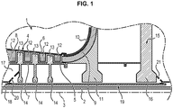
- a turbomachine 1 according to the prior art is shown in figure 1 .
- the turbomachine 1 comprises a low pressure shaft 2 extending along an axis 3 of the turbomachine defining an axis of rotation of the low pressure shaft 2.
- the low pressure shaft 2 is connected upstream with respect to the direction of flow of the air flow in the turbomachine 1 to a low pressure compressor (not shown), and downstream to a low pressure turbine (not shown) which drives it in rotation.
- the turbomachine 1 further comprises, upstream, a high pressure compressor 4 arranged around the low pressure shaft 2 in a coaxial manner.
- the high pressure compressor 4 is an axial-centrifugal compressor.
- the high pressure compressor 4 comprises a rotor 5 and a stator 6 forming a vein through which the air flows.
- the rotor 5 and the stator 6 each have an axial portion, respectively 7 and 8, and a spread portion, respectively 9 and 10.
- the open portion 9 of the rotor 5 is the impeller.
- the impeller 9 comprises a disc 11 movable in rotation about the axis 3 of the turbomachine.
- Fixed vanes 12 and mobile vanes 13 are positioned in the air flow stream.
- the fixed vanes 12 are connected to the stator 6.
- the movable vanes 13 are each connected to a disc 14.
- the discs 14 are connected to the rotor 5 and are movable in rotation about the axis 3 of the turbomachine.
- the turbomachine 1 also comprises, downstream, a high pressure turbine 15 arranged around the low pressure shaft 2 in a coaxial manner.
- the high pressure turbine 15 comprises at least one stage provided with a disc 16 movable in rotation about the axis 3.
- the disc 16 of the high pressure turbine 15 is connected to the disc 11 of the impeller 9 and therefore to the rotor 5.
- the circuit between the low pressure shaft 2 and the rotor 5, also called the inter shaft circuit, is subjected to very high temperature constraints due to the flow of air through the high pressure compressor 4 and the high pressure turbine 15.
- the transmission shafts of the turbomachine 1, in particular the low pressure shaft 2, are supported and guided by bearings, housed in bearing enclosures, where they are supplied with lubricating oil.
- the turbomachine 1 further comprises a tubular sleeve 19 extending along the low pressure shaft 2 along the axis 3 of the turbomachine.
- the sleeve 19 is connected, upstream, to the high pressure compressor 4 by means of a journal 20, and downstream, to the high pressure turbine 15 by means of a journal 21.
- the sleeve 19 separates the cooling circuit 17 passing through the inter-shaft circuit and the pressurization circuit 18 of the bearing enclosures
- the air flows through the cooling circuit 17 between the sleeve 19 and the rotor 5 and through the pressurization circuit 18 between the sleeve 19 and the low pressure shaft 2 at different pressure levels.
- the sheath 19 therefore allows preserving the thermal state of the low pressure shaft 2 on the one hand, and ensuring adequate pressurization of the bearing enclosures on the other hand.
- the sleeve 19 rotates around the axis 3 of the low pressure shaft 2 and turns in the opposite direction to the latter.
- the sleeve 19 resonates and vibrates.
- the object of the present invention is to remedy the problems described above.
- the present invention relates to a turbomachine comprising a compressor stage and a turbine stage, each stage comprising at least one disc movable in rotation about an axis of the turbomachine, and a tubular shaft sleeve s 'extending along the axis of the turbomachine, comprising at least one lug extending from an outer radial surface of the sleeve and facing the disc of the compressor stage or of the turbine stage, the lug being configured to come in contact with the disc when the sleeve is rotating about the axis of the turbomachine.
- Such a turbomachine has the advantage of presenting limited risks of damage due to vibrations of the sleeve.
- the tab comprises a base extending substantially radially from the outer radial surface of the sheath and a contact part extending from the base towards a free end of the tab, the part of contact being configured to deform elastically and come into contact with the disc when the sleeve is in rotation about the axis of the turbomachine.
- the contact part is locally thinned in a zone adjacent to the base, in which the contact part comprises an external surface extending facing the disc and forming, at the level of the free end of the tab, a first contact zone intended to come into contact with the disc over a first range of rotational speeds of the sleeve, and in which the outer surface of the contact part comprises a first surface portion defined by the first contact zone, and a second surface portion, extending in the extension of the first surface portion and being offset radially towards the disc so as to define a vertex, said vertex forming a second contact zone intended to come into contact with the disc on a second range of shaft rotation speeds.
- the outer surface of the tab comprises a protective layer in order to limit wear on the tab.
- the lug comprises a base extending substantially radially from the outer radial surface of the sleeve, the base being configured to come into contact with the disc when the sleeve is in rotation around the sleeve. axis and deforms radially with respect to said axis.
- the contact part extends substantially tangentially with respect to the sheath. According to one variant, the contact part extends parallel to the axis of the turbomachine.
- the sheath comprises a first tube, one end of which cooperates with one end of a second tube, the tab extending at the end of the first tube, from an external radial surface of said first tube.
- the disc comprises a bearing surface, the lug of the sleeve being configured to come into contact with the bearing surface, when the sleeve is in rotation about the axis.
- the subject of the invention is also a shaft sleeve extending along an axis, the sleeve being characterized in that it comprises at least one tab extending from an outer radial surface of the tube, and in that the tab is configured to come into contact with a disc of a compressor or turbine stage of a turbomachine as described above, when the sleeve is rotating about the axis.
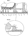
- the figure 2 shows a partial view, in longitudinal section, of a turbomachine 30 comprising a low pressure shaft 31 extending along an axis 32 of the turbomachine defining an axis of rotation of the low pressure shaft 31.
- the turbomachine 30 further comprises a sleeve 33 extending around the low pressure shaft 31 along the axis 32 of the turbomachine.
- the sheath 33 is in two parts.
- the sleeve 33 comprises a first tube 34, a first end of which is connected to a journal 35 of a high pressure compressor 36.
- the sleeve 33 further comprises a second tube 37, a first end of which is connected to a journal 38 of a turbine.
- high pressure 39 and a second end of which is threaded and cooperates with a complementary thread formed inside a second end of the first tube 34.
- the sheath 33 comprises at least one tab 40 extending from an outer radial surface 41 of the first tube 34.
- the tab 40 is disposed at the second end of the first tube 34.
- the tab 40 extends opposite a disc 42 connected to an impeller 43 of the high pressure compressor 36.
- the disc 42 of the impeller 43 comprises an annular bearing surface 44 extending parallel to the axis 32 of the turbomachine from the disc 42 of the impeller 43.
- the annular bearing surface 44 has an internal surface opposite which the tab 40 extends.
- the tab 40 and the scope 44 are particularly visible on the figure 2a .
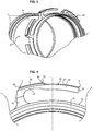
- the figure 3 shows a perspective view of the first tube 34 of the sheath 33.
- the sheath 33 comprises several tabs 40 arranged around the entire circumference of the first tube 34. Preferably, a distance between two adjacent tabs 40 is constant.
- the figure 4 shows a detail view, in cross section, of the sleeve 33 where a tab 40 appears.
- the tab 40 has the general shape of L.
- the tab 40 comprises a base 45 extending substantially radially with respect to the axis 32 of the turbomachine, from the external radial surface 41 to a top 46.
- the tab 40 comprises also a contact portion 47 extending from the base 45 to a free end 48 of the tab 40.
- the contact portion 47 extends substantially parallel to the circumference of the first tube 34. According to a variant not shown, the contact portion 47 can extend substantially parallel to the axis 32 of the turbomachine.
- the contact part 47 is locally thinned in a zone adjacent to the base 45.
- the contact part 47 comprises an internal face 49 facing the external radial surface 41 of the first tube 34 having, between the contact part 47 and the 'base 45, a concave shape, making it possible to increase the deformability of the contact part 47.
- the contact portion 47 further comprises an outer surface 50 extending opposite the disc 42 of the impeller 43. More precisely, the external surface 50 extends opposite the internal face of the annular bearing surface 44 of the disc 42 of the impeller. 43.
- the outer surface 50 of the contact portion 47 forms, at the level of the free end 48 of the tab 40, a first surface portion 51.
- the outer surface 50 of the contact portion 47 comprises a second surface portion 52, extending in the extension of the first surface portion 51.
- the second surface portion 51 is offset radially towards the disc 42 of the impeller 43 so to define a vertex 53.
- the first surface portion 51 defines a first contact zone A.
- the first contact zone A is intended to come into contact with the disc 42 of the impeller 43 over a first range of rotational speeds of the sleeve 33. More precisely, the first contact zone A is intended to come into contact with the internal face of the annular surface 44 of the disc 42 of the impeller 43.
- the first contact zone A of the contact part 47 remains in contact with the disc 42 of the impeller 43 so continues over the first range of rotational speeds of the sleeve 33.
- the first range of rotational speeds of the sleeve 33 preferably covers low rotational speeds, close to the stop of the sleeve 33.
- the first range of rotational speeds of the sleeve 33 includes, for example, rotational speeds between 8000 and 12000 revolutions / min.
- the top 53 of the outer surface 50 forms a second contact zone B intended to come into contact with the disc 42 of the impeller 43 over a second range of rotational speeds of the sleeve 33. More precisely, the second contact zone B is intended to come into contact with the internal face of the annular surface 44 of the disc 42 of the impeller 43. The second contact zone B of the contact part 47 remains in contact with the disc 42 of the impeller 43 continuously over the second range of rotational speeds of the sleeve 33.
- the second range of rotational speeds of the sleeve 33 preferably comprises the highest rotational speeds of the first range of rotational speeds of the sleeve 33. Thus, on the second range of rotational speeds of the sleeve 33.
- the second range of rotational speeds of the sleeve 33 includes, for example, rotation speeds between 12,000 and 25,000 revolutions / min.
- the base 45 comprises a third contact zone C disposed at the level of the top 46 of the base 45 and intended to come into contact with the disc 42 of the impeller 43, when the sleeve 33 is in rotation around the axis 32 of the turbomachine and deforms radially with respect to said axis.
- a radial deformation of the sleeve 33 occurs when the sleeve 33 reaches a critical speed of rotation and starts to vibrate or in the event of strong unbalance, resonance or breakage of a lug 40.
- the third contact zone C is intended to come into contact with the internal face of the annular bearing surface 44 of the disc 42 of the impeller 43.
- the contact portion 47 is elastically deformed, the free end 48 of the tab 40 rises in the direction of the disc 42 of the impeller 43 under the effect of the rotation of the sleeve 33 and the first contact zone A of the contact part 47 comes into contact with the disc 42 of the impeller 43.
- the contact between the first contact zone A and the disc 42 of the impeller 43 has the effect of increasing a value of the critical rotational speeds of the sleeve 33.
- the critical rotational speeds of the sleeve 33 correspond to the rotational speeds at which the sleeve 33 enters. in resonance and begins to vibrate.
- the contact portion 47 deforms further until the contact area B also comes into contact with the disc 42 of the sleeve. impeller 43.
- the addition of contact between the second contact zone B and the disc 42 of impeller 43 has the effect of further increasing a value of the critical rotational speeds of the sleeve 33.
- the radial deformations of the sleeve 33 relative to the axis 32 of the turbomachine are also limited by the base 45 of tab 40.
- the tab 40 is configured to come into contact with the disc 42 of the impeller 43, when the sleeve 33 is in rotation about the axis 32 of the turbomachine. More precisely, the tab 40 is configured so as to come into contact with the disc 42 of the impeller 43 only when the sleeve 33 is in rotation around the axis 32 of the turbomachine. In other words, the tab 40 is not in contact with the disc 42 of the impeller 43, when the sleeve 33 is stationary, and the tab 40 is in contact with disc 42 of impeller 43, when sleeve 33 is driven in a rotational movement around axis 32 of the turbomachine.
- the outer surface 50 of the contact portion 47 comprises a protective layer intended to protect the tab 40 from the friction generated during the contacts between the first, second and third contact zones A, B and C and the disc 42 of the impeller 43.
- the tab 40 is disposed opposite one of the discs 54 of the high pressure compressor 36 or of the disc 55 of the high pressure turbine 39, and is configured to come into contact with the disc 54 or 55 opposite which it s 'extends.
- the disc 54 or 55 with which the lug 40 comes into contact can also include an annular surface similar to the annular surface 44 of the disc 42 of the impeller 43.
Applications Claiming Priority (2)
| Application Number | Priority Date | Filing Date | Title |
|---|---|---|---|
| FR1361593A FR3013766B1 (fr) | 2013-11-25 | 2013-11-25 | Turbomachine comprenant un fourreau d'arbre et tube de fourreau associe |
| PCT/FR2014/053022 WO2015075405A1 (fr) | 2013-11-25 | 2014-11-25 | Turbomachine comprenant un fourreau d'arbre et tube de fourreau associe |
Publications (2)
| Publication Number | Publication Date |
|---|---|
| EP3074597A1 EP3074597A1 (fr) | 2016-10-05 |
| EP3074597B1 true EP3074597B1 (fr) | 2020-09-23 |
Family
ID=49917165
Family Applications (1)
| Application Number | Title | Priority Date | Filing Date |
|---|---|---|---|
| EP14821738.3A Active EP3074597B1 (fr) | 2013-11-25 | 2014-11-25 | Turbomachine comprenant un fourreau d'arbre et tube de fourreau associé |
Country Status (8)
| Country | Link |
|---|---|
| US (1) | US10267154B2 (ja) |
| EP (1) | EP3074597B1 (ja) |
| JP (1) | JP6619746B2 (ja) |
| CN (1) | CN105765167B (ja) |
| CA (1) | CA2931307C (ja) |
| FR (1) | FR3013766B1 (ja) |
| RU (1) | RU2668507C1 (ja) |
| WO (1) | WO2015075405A1 (ja) |
Families Citing this family (3)
| Publication number | Priority date | Publication date | Assignee | Title |
|---|---|---|---|---|
| CN109555728A (zh) * | 2017-05-23 | 2019-04-02 | 何金星 | 一种叶轮壳衬套 |
| FR3079550B1 (fr) * | 2018-03-27 | 2020-10-23 | Safran Aircraft Engines | Arbre de turbine d'une turbomachine et procede de protection contre une survitesse dudit arbre |
| CN113107676B (zh) * | 2021-05-19 | 2022-05-27 | 中国科学院工程热物理研究所 | 三层套筒式中心拉杆装置 |
Citations (1)
| Publication number | Priority date | Publication date | Assignee | Title |
|---|---|---|---|---|
| US4190398A (en) * | 1977-06-03 | 1980-02-26 | General Electric Company | Gas turbine engine and means for cooling same |
Family Cites Families (13)
| Publication number | Priority date | Publication date | Assignee | Title |
|---|---|---|---|---|
| GB912331A (en) * | 1960-06-07 | 1962-12-05 | Rolls Royce | Bearing assembly |
| US5232335A (en) * | 1991-10-30 | 1993-08-03 | General Electric Company | Interstage thermal shield retention system |
| JP3276455B2 (ja) * | 1993-04-26 | 2002-04-22 | 三菱重工業株式会社 | ダイアフラム継手 |
| FR2712029B1 (fr) | 1993-11-03 | 1995-12-08 | Snecma | Turbomachine pourvue d'un moyen de réchauffage des disques de turbines aux montées en régime. |
| US5555721A (en) * | 1994-09-28 | 1996-09-17 | General Electric Company | Gas turbine engine cooling supply circuit |
| US6043780A (en) | 1995-12-27 | 2000-03-28 | Funk; Thomas J. | Antenna adapter |
| GB2326679B (en) * | 1997-06-25 | 2000-07-26 | Rolls Royce Plc | Ducted fan gas turbine engine |
| FR2783579B1 (fr) * | 1998-09-17 | 2000-11-03 | Snecma | Agencement de retenue d'un palier, notamment pour un arbre de compresseur a haute pression |
| JP2005054738A (ja) * | 2003-08-07 | 2005-03-03 | Ishikawajima Harima Heavy Ind Co Ltd | 高速回転機械の潤滑油供給装置と2重構造の回転軸 |
| EP1970533A1 (de) * | 2007-03-12 | 2008-09-17 | Siemens Aktiengesellschaft | Turbine mit mindestens einem Rotor bestehend aus Rotorscheiben und einen Zuganker |
| FR2931873B1 (fr) | 2008-05-29 | 2010-08-20 | Snecma | Ensemble d'un disque de turbine d'un moteur a turbine a gaz et d'un tourillon support de palier,circuit de refroidissement d'un disque de turbine d'un tel ensemble. |
| FR2943035B1 (fr) | 2009-03-11 | 2012-09-28 | Snecma | Dispositif d'entrainement d'une paire d'helices contrarotives par un train epycycloidal |
| FR2981124B1 (fr) * | 2011-10-07 | 2016-04-01 | Snecma | Fourreau de protection d'un arbre de turbomachine |
-
2013
- 2013-11-25 FR FR1361593A patent/FR3013766B1/fr not_active Expired - Fee Related
-
2014
- 2014-11-25 JP JP2016554922A patent/JP6619746B2/ja active Active
- 2014-11-25 RU RU2016125491A patent/RU2668507C1/ru active
- 2014-11-25 WO PCT/FR2014/053022 patent/WO2015075405A1/fr active Application Filing
- 2014-11-25 EP EP14821738.3A patent/EP3074597B1/fr active Active
- 2014-11-25 CN CN201480064235.5A patent/CN105765167B/zh active Active
- 2014-11-25 CA CA2931307A patent/CA2931307C/fr active Active
- 2014-11-25 US US15/038,732 patent/US10267154B2/en active Active
Patent Citations (1)
| Publication number | Priority date | Publication date | Assignee | Title |
|---|---|---|---|---|
| US4190398A (en) * | 1977-06-03 | 1980-02-26 | General Electric Company | Gas turbine engine and means for cooling same |
Also Published As
| Publication number | Publication date |
|---|---|
| FR3013766B1 (fr) | 2017-11-10 |
| US10267154B2 (en) | 2019-04-23 |
| CN105765167B (zh) | 2021-03-02 |
| FR3013766A1 (fr) | 2015-05-29 |
| JP6619746B2 (ja) | 2019-12-11 |
| JP2016538483A (ja) | 2016-12-08 |
| CA2931307A1 (fr) | 2015-05-28 |
| CN105765167A (zh) | 2016-07-13 |
| US20160362982A1 (en) | 2016-12-15 |
| WO2015075405A1 (fr) | 2015-05-28 |
| RU2016125491A (ru) | 2018-01-09 |
| CA2931307C (fr) | 2021-08-31 |
| EP3074597A1 (fr) | 2016-10-05 |
| RU2668507C1 (ru) | 2018-10-01 |
Similar Documents
| Publication | Publication Date | Title |
|---|---|---|
| CA2650771C (fr) | Centrage d'une piece a l'interieur d'un arbre | |
| FR2899275A1 (fr) | Dispositif de fixation de secteurs d'anneau sur un carter de turbine d'une turbomachine | |
| FR3071546B1 (fr) | Retention axiale de l'arbre de soufflante dans un moteur a turbine a gaz | |
| CA2537672A1 (fr) | Carter interne de turbomachine equipe d'un bouclier thermique | |
| WO2010072968A1 (fr) | Roue mobile de turbomachine a aubes en materiau composite munie d'un anneau ressort | |
| FR2980235A1 (fr) | Anneau pour une turbine de turbomachine | |
| CA2647058A1 (fr) | Etancheite d'une cavite de moyeu d'un carter d'echappement dans une turbomachine | |
| EP2901021B2 (fr) | Carter et roue a aubes de turbomachine | |
| EP3074597B1 (fr) | Turbomachine comprenant un fourreau d'arbre et tube de fourreau associé | |
| FR2975428A1 (fr) | Roue a aubes de turbomachine | |
| EP3759319B1 (fr) | Ensemble pour une turbomachine | |
| FR2971022A1 (fr) | Etage redresseur de compresseur pour une turbomachine | |
| EP2917518B1 (fr) | Support de tube d'évacuation d'air dans une turbomachine | |
| FR2985766A1 (fr) | Agencement pour le guidage de l'ecoulement d'un liquide par rapport au rotor d'une turbomachine | |
| CA2646976A1 (fr) | Etancheite de fixation de support de palier dans une turbomachine | |
| FR2993599A1 (fr) | Disque labyrinthe de turbomachine | |
| EP1936125B1 (fr) | Compresseur de turbomachine | |
| FR2888877A1 (fr) | Dispositif d'amortissement des vibrations d'un rotor | |
| FR2985763A1 (fr) | Dispositif d'etancheite inter-arbre coaxiaux d'une turbomachine | |
| FR2998672A1 (fr) | Rotor de turbomachine ou de moteur d'essai | |
| FR3025554B1 (fr) | Rotor de turbomachine avec segment de retention axiale des aubes | |
| FR3057904A1 (fr) | Dispositif d'amortissement ameliore pour compresseur de turbomachine | |
| FR3129174A1 (fr) | Module de turbomachine comprenant un dispositif d’amortissement et turbomachine correspondante | |
| FR3097255A1 (fr) | Organe de stator pour turbomachine comportant un revêtement périphérique | |
| FR3129175A1 (fr) | Module de turbomachine avec un dispositif de limitation d’amplitude et turbomachine correpondante |
Legal Events
| Date | Code | Title | Description |
|---|---|---|---|
| PUAI | Public reference made under article 153(3) epc to a published international application that has entered the european phase |
Free format text: ORIGINAL CODE: 0009012 |
|
| 17P | Request for examination filed |
Effective date: 20160624 |
|
| AK | Designated contracting states |
Kind code of ref document: A1 Designated state(s): AL AT BE BG CH CY CZ DE DK EE ES FI FR GB GR HR HU IE IS IT LI LT LU LV MC MK MT NL NO PL PT RO RS SE SI SK SM TR |
|
| AX | Request for extension of the european patent |
Extension state: BA ME |
|
| DAX | Request for extension of the european patent (deleted) | ||
| RAP1 | Party data changed (applicant data changed or rights of an application transferred) |
Owner name: SAFRAN AIRCRAFT ENGINES |
|
| STAA | Information on the status of an ep patent application or granted ep patent |
Free format text: STATUS: EXAMINATION IS IN PROGRESS |
|
| 17Q | First examination report despatched |
Effective date: 20190910 |
|
| GRAP | Despatch of communication of intention to grant a patent |
Free format text: ORIGINAL CODE: EPIDOSNIGR1 |
|
| STAA | Information on the status of an ep patent application or granted ep patent |
Free format text: STATUS: GRANT OF PATENT IS INTENDED |
|
| INTG | Intention to grant announced |
Effective date: 20200420 |
|
| GRAS | Grant fee paid |
Free format text: ORIGINAL CODE: EPIDOSNIGR3 |
|
| GRAA | (expected) grant |
Free format text: ORIGINAL CODE: 0009210 |
|
| STAA | Information on the status of an ep patent application or granted ep patent |
Free format text: STATUS: THE PATENT HAS BEEN GRANTED |
|
| AK | Designated contracting states |
Kind code of ref document: B1 Designated state(s): AL AT BE BG CH CY CZ DE DK EE ES FI FR GB GR HR HU IE IS IT LI LT LU LV MC MK MT NL NO PL PT RO RS SE SI SK SM TR |
|
| REG | Reference to a national code |
Ref country code: GB Ref legal event code: FG4D Free format text: NOT ENGLISH |
|
| REG | Reference to a national code |
Ref country code: CH Ref legal event code: EP |
|
| REG | Reference to a national code |
Ref country code: IE Ref legal event code: FG4D Free format text: LANGUAGE OF EP DOCUMENT: FRENCH |
|
| REG | Reference to a national code |
Ref country code: DE Ref legal event code: R096 Ref document number: 602014070551 Country of ref document: DE Ref country code: AT Ref legal event code: REF Ref document number: 1316550 Country of ref document: AT Kind code of ref document: T Effective date: 20201015 |
|
| REG | Reference to a national code |
Ref country code: SE Ref legal event code: TRGR |
|
| PG25 | Lapsed in a contracting state [announced via postgrant information from national office to epo] |
Ref country code: HR Free format text: LAPSE BECAUSE OF FAILURE TO SUBMIT A TRANSLATION OF THE DESCRIPTION OR TO PAY THE FEE WITHIN THE PRESCRIBED TIME-LIMIT Effective date: 20200923 Ref country code: BG Free format text: LAPSE BECAUSE OF FAILURE TO SUBMIT A TRANSLATION OF THE DESCRIPTION OR TO PAY THE FEE WITHIN THE PRESCRIBED TIME-LIMIT Effective date: 20201223 Ref country code: GR Free format text: LAPSE BECAUSE OF FAILURE TO SUBMIT A TRANSLATION OF THE DESCRIPTION OR TO PAY THE FEE WITHIN THE PRESCRIBED TIME-LIMIT Effective date: 20201224 Ref country code: FI Free format text: LAPSE BECAUSE OF FAILURE TO SUBMIT A TRANSLATION OF THE DESCRIPTION OR TO PAY THE FEE WITHIN THE PRESCRIBED TIME-LIMIT Effective date: 20200923 Ref country code: NO Free format text: LAPSE BECAUSE OF FAILURE TO SUBMIT A TRANSLATION OF THE DESCRIPTION OR TO PAY THE FEE WITHIN THE PRESCRIBED TIME-LIMIT Effective date: 20201223 |
|
| REG | Reference to a national code |
Ref country code: AT Ref legal event code: MK05 Ref document number: 1316550 Country of ref document: AT Kind code of ref document: T Effective date: 20200923 |
|
| PG25 | Lapsed in a contracting state [announced via postgrant information from national office to epo] |
Ref country code: RS Free format text: LAPSE BECAUSE OF FAILURE TO SUBMIT A TRANSLATION OF THE DESCRIPTION OR TO PAY THE FEE WITHIN THE PRESCRIBED TIME-LIMIT Effective date: 20200923 Ref country code: LV Free format text: LAPSE BECAUSE OF FAILURE TO SUBMIT A TRANSLATION OF THE DESCRIPTION OR TO PAY THE FEE WITHIN THE PRESCRIBED TIME-LIMIT Effective date: 20200923 |
|
| REG | Reference to a national code |
Ref country code: NL Ref legal event code: MP Effective date: 20200923 |
|
| REG | Reference to a national code |
Ref country code: LT Ref legal event code: MG4D |
|
| PG25 | Lapsed in a contracting state [announced via postgrant information from national office to epo] |
Ref country code: SM Free format text: LAPSE BECAUSE OF FAILURE TO SUBMIT A TRANSLATION OF THE DESCRIPTION OR TO PAY THE FEE WITHIN THE PRESCRIBED TIME-LIMIT Effective date: 20200923 Ref country code: RO Free format text: LAPSE BECAUSE OF FAILURE TO SUBMIT A TRANSLATION OF THE DESCRIPTION OR TO PAY THE FEE WITHIN THE PRESCRIBED TIME-LIMIT Effective date: 20200923 Ref country code: EE Free format text: LAPSE BECAUSE OF FAILURE TO SUBMIT A TRANSLATION OF THE DESCRIPTION OR TO PAY THE FEE WITHIN THE PRESCRIBED TIME-LIMIT Effective date: 20200923 Ref country code: LT Free format text: LAPSE BECAUSE OF FAILURE TO SUBMIT A TRANSLATION OF THE DESCRIPTION OR TO PAY THE FEE WITHIN THE PRESCRIBED TIME-LIMIT Effective date: 20200923 Ref country code: NL Free format text: LAPSE BECAUSE OF FAILURE TO SUBMIT A TRANSLATION OF THE DESCRIPTION OR TO PAY THE FEE WITHIN THE PRESCRIBED TIME-LIMIT Effective date: 20200923 Ref country code: PT Free format text: LAPSE BECAUSE OF FAILURE TO SUBMIT A TRANSLATION OF THE DESCRIPTION OR TO PAY THE FEE WITHIN THE PRESCRIBED TIME-LIMIT Effective date: 20210125 Ref country code: CZ Free format text: LAPSE BECAUSE OF FAILURE TO SUBMIT A TRANSLATION OF THE DESCRIPTION OR TO PAY THE FEE WITHIN THE PRESCRIBED TIME-LIMIT Effective date: 20200923 |
|
| PG25 | Lapsed in a contracting state [announced via postgrant information from national office to epo] |
Ref country code: ES Free format text: LAPSE BECAUSE OF FAILURE TO SUBMIT A TRANSLATION OF THE DESCRIPTION OR TO PAY THE FEE WITHIN THE PRESCRIBED TIME-LIMIT Effective date: 20200923 Ref country code: AT Free format text: LAPSE BECAUSE OF FAILURE TO SUBMIT A TRANSLATION OF THE DESCRIPTION OR TO PAY THE FEE WITHIN THE PRESCRIBED TIME-LIMIT Effective date: 20200923 Ref country code: AL Free format text: LAPSE BECAUSE OF FAILURE TO SUBMIT A TRANSLATION OF THE DESCRIPTION OR TO PAY THE FEE WITHIN THE PRESCRIBED TIME-LIMIT Effective date: 20200923 Ref country code: IS Free format text: LAPSE BECAUSE OF FAILURE TO SUBMIT A TRANSLATION OF THE DESCRIPTION OR TO PAY THE FEE WITHIN THE PRESCRIBED TIME-LIMIT Effective date: 20210123 Ref country code: PL Free format text: LAPSE BECAUSE OF FAILURE TO SUBMIT A TRANSLATION OF THE DESCRIPTION OR TO PAY THE FEE WITHIN THE PRESCRIBED TIME-LIMIT Effective date: 20200923 |
|
| REG | Reference to a national code |
Ref country code: DE Ref legal event code: R097 Ref document number: 602014070551 Country of ref document: DE |
|
| PG25 | Lapsed in a contracting state [announced via postgrant information from national office to epo] |
Ref country code: MC Free format text: LAPSE BECAUSE OF FAILURE TO SUBMIT A TRANSLATION OF THE DESCRIPTION OR TO PAY THE FEE WITHIN THE PRESCRIBED TIME-LIMIT Effective date: 20200923 Ref country code: SK Free format text: LAPSE BECAUSE OF FAILURE TO SUBMIT A TRANSLATION OF THE DESCRIPTION OR TO PAY THE FEE WITHIN THE PRESCRIBED TIME-LIMIT Effective date: 20200923 |
|
| REG | Reference to a national code |
Ref country code: CH Ref legal event code: PL |
|
| PG25 | Lapsed in a contracting state [announced via postgrant information from national office to epo] |
Ref country code: LU Free format text: LAPSE BECAUSE OF NON-PAYMENT OF DUE FEES Effective date: 20201125 |
|
| PLBE | No opposition filed within time limit |
Free format text: ORIGINAL CODE: 0009261 |
|
| STAA | Information on the status of an ep patent application or granted ep patent |
Free format text: STATUS: NO OPPOSITION FILED WITHIN TIME LIMIT |
|
| REG | Reference to a national code |
Ref country code: BE Ref legal event code: MM Effective date: 20201130 |
|
| PG25 | Lapsed in a contracting state [announced via postgrant information from national office to epo] |
Ref country code: CH Free format text: LAPSE BECAUSE OF NON-PAYMENT OF DUE FEES Effective date: 20201130 Ref country code: DK Free format text: LAPSE BECAUSE OF FAILURE TO SUBMIT A TRANSLATION OF THE DESCRIPTION OR TO PAY THE FEE WITHIN THE PRESCRIBED TIME-LIMIT Effective date: 20200923 Ref country code: SI Free format text: LAPSE BECAUSE OF FAILURE TO SUBMIT A TRANSLATION OF THE DESCRIPTION OR TO PAY THE FEE WITHIN THE PRESCRIBED TIME-LIMIT Effective date: 20200923 Ref country code: LI Free format text: LAPSE BECAUSE OF NON-PAYMENT OF DUE FEES Effective date: 20201130 |
|
| 26N | No opposition filed |
Effective date: 20210624 |
|
| PG25 | Lapsed in a contracting state [announced via postgrant information from national office to epo] |
Ref country code: IE Free format text: LAPSE BECAUSE OF NON-PAYMENT OF DUE FEES Effective date: 20201125 |
|
| PG25 | Lapsed in a contracting state [announced via postgrant information from national office to epo] |
Ref country code: TR Free format text: LAPSE BECAUSE OF FAILURE TO SUBMIT A TRANSLATION OF THE DESCRIPTION OR TO PAY THE FEE WITHIN THE PRESCRIBED TIME-LIMIT Effective date: 20200923 Ref country code: MT Free format text: LAPSE BECAUSE OF FAILURE TO SUBMIT A TRANSLATION OF THE DESCRIPTION OR TO PAY THE FEE WITHIN THE PRESCRIBED TIME-LIMIT Effective date: 20200923 Ref country code: CY Free format text: LAPSE BECAUSE OF FAILURE TO SUBMIT A TRANSLATION OF THE DESCRIPTION OR TO PAY THE FEE WITHIN THE PRESCRIBED TIME-LIMIT Effective date: 20200923 |
|
| PG25 | Lapsed in a contracting state [announced via postgrant information from national office to epo] |
Ref country code: MK Free format text: LAPSE BECAUSE OF FAILURE TO SUBMIT A TRANSLATION OF THE DESCRIPTION OR TO PAY THE FEE WITHIN THE PRESCRIBED TIME-LIMIT Effective date: 20200923 |
|
| PG25 | Lapsed in a contracting state [announced via postgrant information from national office to epo] |
Ref country code: BE Free format text: LAPSE BECAUSE OF NON-PAYMENT OF DUE FEES Effective date: 20201130 |
|
| PGFP | Annual fee paid to national office [announced via postgrant information from national office to epo] |
Ref country code: GB Payment date: 20231019 Year of fee payment: 10 |
|
| PGFP | Annual fee paid to national office [announced via postgrant information from national office to epo] |
Ref country code: SE Payment date: 20231020 Year of fee payment: 10 Ref country code: IT Payment date: 20231019 Year of fee payment: 10 Ref country code: FR Payment date: 20231019 Year of fee payment: 10 Ref country code: DE Payment date: 20231019 Year of fee payment: 10 |