EP3074294B1 - Plate of an electric switch and steering column of a vehicle - Google Patents
Plate of an electric switch and steering column of a vehicle Download PDFInfo
- Publication number
- EP3074294B1 EP3074294B1 EP14806010.6A EP14806010A EP3074294B1 EP 3074294 B1 EP3074294 B1 EP 3074294B1 EP 14806010 A EP14806010 A EP 14806010A EP 3074294 B1 EP3074294 B1 EP 3074294B1
- Authority
- EP
- European Patent Office
- Prior art keywords
- plate
- steering column
- rotation locking
- locking elements
- rotation
- Prior art date
- Legal status (The legal status is an assumption and is not a legal conclusion. Google has not performed a legal analysis and makes no representation as to the accuracy of the status listed.)
- Active
Links
- 239000000463 material Substances 0.000 claims description 10
- 238000003780 insertion Methods 0.000 claims description 5
- 230000037431 insertion Effects 0.000 claims description 5
- 238000000034 method Methods 0.000 claims description 4
- BASFCYQUMIYNBI-UHFFFAOYSA-N platinum Chemical compound [Pt] BASFCYQUMIYNBI-UHFFFAOYSA-N 0.000 description 6
- 239000007787 solid Substances 0.000 description 4
- 230000000903 blocking effect Effects 0.000 description 2
- 230000014759 maintenance of location Effects 0.000 description 1
- 238000004519 manufacturing process Methods 0.000 description 1
- 238000000465 moulding Methods 0.000 description 1
- 238000010137 moulding (plastic) Methods 0.000 description 1
- 229910052697 platinum Inorganic materials 0.000 description 1
Images


Classifications
-
- B—PERFORMING OPERATIONS; TRANSPORTING
- B62—LAND VEHICLES FOR TRAVELLING OTHERWISE THAN ON RAILS
- B62D—MOTOR VEHICLES; TRAILERS
- B62D1/00—Steering controls, i.e. means for initiating a change of direction of the vehicle
- B62D1/02—Steering controls, i.e. means for initiating a change of direction of the vehicle vehicle-mounted
- B62D1/16—Steering columns
Definitions
- the invention relates to the attachment of an electrical switch plate on a steering column of a vehicle, especially automobile. More specifically, according to the invention, such a plate comprises a plurality of anti-rotation locking elements of the plate relative to the steering column.
- Such a switch is generally in the form of a housing mounted on the steering column of the vehicle.
- the housing comprises on its rear face a plate having an axially split shaft in which the steering column is inserted and which is then fixed on the column by means of a clamping collar.
- EP1 319 573 A discloses a module for attachment to a steering column of a vehicle by means of a fastener forming such a clamp.
- a known solution consists in adding an anti-rotation locking element to the plate and arranging on the steering column a cutout arranged to receive said element.
- Such an element is in the form of a portion of material of the plate projecting in a direction parallel to the axis of the drum.
- the object of the invention is to propose an electric switch plate and a steering column comprising reliable rotational locking means which make the connection between the platen and the column both stable, rigid and robust while providing user comfort for the driver of the vehicle.
- the invention firstly relates to a plate intended to be mounted on a steering column of a vehicle, said plate comprising a plate of which extends orthogonally a split shaft axially able to be clamped around said steering column, said plate being remarkable in that it comprises a plurality of anti-rotation locking elements, preferably two elements, each arranged to cooperate by embedding with a cutout of the steering column.
- the anti-rotation locking elements project into the barrel parallel to its axis.
- the plate comprises two anti-rotation locking elements
- the two anti-rotation locking elements are diametrically opposed relative to the axis of the drum.
- the symmetrical arrangement of anti-rotation locking elements makes it possible in particular to make the connection between the plate and the steering column stable and comfortable for the operator of the vehicle steering wheel.
- the anti-rotation locking elements comprise at least one portion made of a deformable material, preferably a plastic material, and arranged to be deformed during the embedment of the anti-rotation locking element in the blank corresponding of the steering column.
- a deformable portion makes it possible to make the connection between the plate and the steering column is thus both solid and reliable while securely locking the plate in rotation relative to the steering column.
- said portion comprises at least one rib extending parallel to the axis of the barrel.
- a rib is easy to make and compress by matting.
- the rib extends over the length of the anti-rotation locking element so as to allow a solid integral embedding of the anti-rotation locking element in the corresponding cutout of the steering column.
- the anti-rotation locking elements are derived from the material of the plate, the plate then being easy to manufacture.
- the invention also relates to a steering column comprising a plurality of cutouts, preferably two cutouts, each arranged to receive by embedding an anti-rotation locking element of a plate as presented above.
- each of the cuts is U-shaped whose ends are beveled to facilitate insertion and allow the matting of the corresponding anti-rotation locking element of the plate.
- the invention also relates to an assembly formed of a plate and a steering column as presented above, the anti-rotation locking elements of the plate being embedded in the corresponding cuts of the steering column.
- the invention likewise relates to a vehicle comprising an assembly as presented above.
- the invention finally relates to a method of mounting an assembly as presented above, said method being remarkable in that it comprises a step of inserting force by embedding anti-rotation locking elements of the plate in the cuts corresponding of the steering column.
- in force is meant that, the width of the anti-rotation locking elements being greater than or equal to the width of the cuts, it is necessary to exert an embedding force of the anti-rotation locking elements in their respective cuts.
- the embodiment described is more particularly related to an implementation of the plate according to the invention to a steering column of a vehicle, particularly in the automotive field.
- any implementation in a different context, in order to provide a rotational locking function of a plate on a support such as an arm, is also covered by the present invention.
- the figure 1 illustrates a non-limiting embodiment of a plate 1 according to the invention.
- Platen 1 is shown only schematically in this appended figure. It is preferably a plate of an electrical switch (not shown).
- the plate 1 can be made of any suitable known material. Preferably, the plate 1 is made by plastic molding.
- the plate 1 can support active members of the electrical switch, including electrically conductive blades.
- the plate 1 is formed of a plate 1a but can of course be the subject of any variant adapted to the constraints of the electrical switch.
- the plate 1 comprises a shaft 2 extending orthogonally to the plate 1a along an axis X which makes it possible to fix the plate 1 on a steering column 20 (with reference to FIG. figure 5 ).
- the barrel 2 is axially slit orthogonal to the plate 1a.
- the internal diameter of the slit drum 2 at rest is adapted to be engaged around the steering column 20 of the vehicle (not shown) and then clamped on said column 20 with the aid of a clamp 3 and a screw and nut system 4.
- any other clamping means could be used.
- the plate 1 comprises, inside the barrel 2, a first annular element 5 of axis X and a second annular element 6 of axis X.
- the second annular element 6 of smaller diameter than the first annular element 5 defines an opening 7 arranged to receive a portion (not shown) of the steering column 20.
- the first annular element 5 extends from the plate 1a and comprises two support portions 8 projecting inside the barrel 2 parallel to the axis X.
- the plate 1 comprises in this example two diametrically opposite anti-rotation locking elements disposed inside the barrel 2.
- Each of the two anti-rotation locking elements 10 is in the form of a portion of material from the plate 1 which extends projecting parallel to the axis X of the barrel 2 between one of the support portions 8 and the barrel 2 from the annular element 5.
- the anti-rotation locking elements 10 are each arranged to cooperate by fitting with a cutout 30 of the steering column 20 (with reference to FIGS. Figures 5 and 6 ) as explained below.
- a plurality of anti-rotation locking elements 10 is provided on the plate 1 in order to lock it in rotation with respect to column 20.
- the cross section of the anti-rotation locking elements 10 is substantially in the form of an arc of a curvature whose value is of the order of that of the cutout 30 of the steering column 20 in order to allow a solid embedding.
- the anti-rotation locking elements 10 are made during the molding of the plate 1 in a manner known to those skilled in the art.
- the anti-rotation locking elements 10 may be attached to the plate 1.
- each anti-rotation locking element 10 comprises a portion made of a deformable plastic material, for example of PA6GF30 type known to those skilled in the art, so as to be deformed by matting when it is embedded in the corresponding cutout 30 of the steering column 20.
- a deformable plastic material for example of PA6GF30 type known to those skilled in the art
- said portion comprises a rib 12 configured to deform by matting during the force-embedding of the anti-rotation locking element 10 in the corresponding cutout 30 of the steering column 20.
- the width L1 of the anti-rotation locking element 10 at rest (ie before embedding) with the rib 12 is thus greater than or equal to the width L2 of the corresponding cutout 30 of the steering column 20.
- the width L2 of the blank 30 may be of the order of 12 mm and the width L1 of the anti-rotation locking element 10 at rest may be 12.225 mm, the rib 12 having a thickness of, for example, 0.225 mm.
- an anti-locking element rotation may comprise more than one portion made of a deformable material to allow it to be embedded in the corresponding cutout.
- these ribs 12 may be of a different thickness, for example smaller than 12.225 mm so as to avoid having to exert too much embedding force.
- the steering column 20 comprises two cutouts 30 each arranged to receive by embedding an anti-rotation locking element 10 of the plate 1.
- each of the cutouts 30 is U-shaped, the ends 32 of which are bevelled in order to facilitate the insertion and to allow the corresponding anti-rotation blocking element 10 of the plate 1 to be matted.
- the anti-rotation blocking elements 10 are first positioned opposite the corresponding cutouts 30 of the steering column 20.
- each of the anti-rotation locking elements 10 of the plate 1 is inserted into the corresponding cutout 30 of the steering column 20, the beveled ends 32 of the cuts facilitating the insertion and the embedding and the ribs. 12 deforming during embedding to securely hold the anti-rotation locking elements 10 embedded in the cutouts 30.
- the barrel 2 is tightened around the steering column 20 by means of the clamping means 3 and 4.
- anti-rotation locking elements 10 and cutouts 30 of different shapes taking into account the structure of the plate 1 and / or the structure of the column of direction 20.
- the present invention is not limited to the examples described above and is capable of numerous variants accessible to those skilled in the art.
- shape and dimensions of the plate 1, the barrel 3, anti-rotation locking elements 10, the steering column 20 and the cutouts 30 as shown in the figures so as to illustrate an exemplary embodiment of FIG. the invention can not be interpreted as limiting.
Description
L'invention concerne la fixation d'une platine de commutateur électrique sur une colonne de direction d'un véhicule, notamment automobile. Plus précisément, selon l'invention, une telle platine comprend une pluralité d'éléments de blocage anti-rotation de la platine par rapport à la colonne de direction.The invention relates to the attachment of an electrical switch plate on a steering column of a vehicle, especially automobile. More specifically, according to the invention, such a plate comprises a plurality of anti-rotation locking elements of the plate relative to the steering column.
Dans un véhicule automobile, il est connu d'actionner certaines commandes des équipements du véhicule depuis le tableau de bord, par exemple les feux clignotants ou les balais d'essuie-glace. De telles commandes sont connectées auxdits équipements via un commutateur électrique.In a motor vehicle, it is known to operate certain commands of the vehicle equipment from the dashboard, for example flashing lights or wiper blades. Such commands are connected to said equipment via an electrical switch.
Un tel commutateur se présente généralement sous la forme d'un boitier monté sur la colonne de direction du véhicule. Pour ce faire, le boitier comprend sur sa face arrière une platine comportant un fût fendu axialement dans lequel on insère la colonne de direction et qui est ensuite fixé sur la colonne à l'aide d'un collier de serrage. Par exemple,
Le serrage d'un tel collier ne permet cependant pas de bloquer complètement la platine en rotation par rapport à la colonne de direction.Clamping such a collar does not allow to completely block the turntable relative to the steering column.
Afin de résoudre au moins en partie ce problème, une solution connue consiste à ajouter un élément de blocage anti-rotation sur la platine et à ménager sur la colonne de direction une découpe agencée pour recevoir ledit élément. Un tel élément se présente sous la forme d'une portion de matière de la platine s'étendant en saillie selon une direction parallèle à l'axe du fût.In order to at least partially solve this problem, a known solution consists in adding an anti-rotation locking element to the plate and arranging on the steering column a cutout arranged to receive said element. Such an element is in the form of a portion of material of the plate projecting in a direction parallel to the axis of the drum.
Une telle solution n'est toutefois pas satisfaisante dans la mesure où il peut exister un jeu angulaire entre l'élément de blocage anti-rotation et la découpe qui peut aboutir à un montage en travers de la platine sur la colonne de direction ou provoquer une sensation inconfortable pour le conducteur du véhicule lorsqu'il tourne le volant ou bien encore créer des perturbations sonores. De plus, dans une telle solution, la liaison entre la platine et la colonne de direction n'est pas suffisamment robuste et rigide et le blocage en rotation n'est toujours pas satisfaisant.Such a solution is however not satisfactory insofar as there may be an angular clearance between the anti-rotation locking element and the cutout which may lead to mounting across the plate on the steering column or cause a uncomfortable feeling for the driver of the vehicle while turning the steering wheel or creating noise disturbances. In addition, in such a solution, the connection between the plate and the steering column is not sufficiently robust and rigid and the locking in rotation is still not satisfactory.
Afin de résoudre au moins en partie ces inconvénients, l'invention a pour but de proposer une platine de commutateur électrique et une colonne de direction comprenant des moyens de blocage en rotation fiables qui rendent la liaison entre la platine et la colonne à la fois stable, rigide et robuste tout en procurant un confort d'utilisation pour le conducteur du véhicule.In order to at least partly solve these disadvantages, the object of the invention is to propose an electric switch plate and a steering column comprising reliable rotational locking means which make the connection between the platen and the column both stable, rigid and robust while providing user comfort for the driver of the vehicle.
A cet effet, l'invention a tout d'abord pour objet une platine destinée à être montée sur une colonne de direction d'un véhicule, ladite platine comprenant une plaque de laquelle s'étend orthogonalement un fût fendu axialement apte à être serré autour de ladite colonne de direction, ladite platine étant remarquable en ce qu'elle comprend une pluralité d'éléments de blocage anti-rotation, de préférence deux éléments, agencés chacun pour coopérer par encastrement avec une découpe de la colonne de direction.For this purpose, the invention firstly relates to a plate intended to be mounted on a steering column of a vehicle, said plate comprising a plate of which extends orthogonally a split shaft axially able to be clamped around said steering column, said plate being remarkable in that it comprises a plurality of anti-rotation locking elements, preferably two elements, each arranged to cooperate by embedding with a cutout of the steering column.
L'utilisation d'une pluralité d'éléments de blocage anti-rotation permet de rigidifier la liaison entre la platine et la colonne de direction qui est donc plus robuste.The use of a plurality of anti-rotation locking elements makes it possible to stiffen the connection between the plate and the steering column, which is therefore more robust.
De préférence, les éléments de blocage anti-rotation s'étendent en saillie à l'intérieur du fût parallèlement à son axe.Preferably, the anti-rotation locking elements project into the barrel parallel to its axis.
De préférence encore, lorsque la platine comprend deux éléments de blocage anti-rotation, les deux éléments de blocage anti-rotation sont diamétralement opposés par rapport à l'axe du fût. La disposition symétrique des éléments de blocage anti-rotation permet notamment de rendre la liaison entre la platine et la colonne de direction stable et confortable pour l'opérateur du volant du véhicule.More preferably, when the plate comprises two anti-rotation locking elements, the two anti-rotation locking elements are diametrically opposed relative to the axis of the drum. The symmetrical arrangement of anti-rotation locking elements makes it possible in particular to make the connection between the plate and the steering column stable and comfortable for the operator of the vehicle steering wheel.
De manière avantageuse, les éléments de blocage anti-rotation comprennent au moins une portion réalisée en un matériau déformable, de préférence un matériau plastique, et agencée pour être déformée lors de l'encastrement de l'élément de blocage anti-rotation dans la découpe correspondante de la colonne de direction. L'utilisation d'une portion déformable permet de rendre la liaison entre la platine et la colonne de direction est ainsi à la fois solide et fiable tout en bloquant solidement en rotation la platine par rapport à la colonne de direction.Advantageously, the anti-rotation locking elements comprise at least one portion made of a deformable material, preferably a plastic material, and arranged to be deformed during the embedment of the anti-rotation locking element in the blank corresponding of the steering column. The use of a deformable portion makes it possible to make the connection between the plate and the steering column is thus both solid and reliable while securely locking the plate in rotation relative to the steering column.
Avantageusement encore, ladite portion comprend au moins une nervure s'étendant parallèlement à l'axe du fût. Une telle nervure est aisée à réaliser et à compresser par matage.Advantageously, said portion comprises at least one rib extending parallel to the axis of the barrel. Such a rib is easy to make and compress by matting.
De manière préférée, la nervure s'étend sur la longueur de l'élément de blocage anti-rotation de sorte à permettre un encastrement intégral solide de l'élément de blocage anti-rotation dans la découpe correspondante de la colonne de direction.Preferably, the rib extends over the length of the anti-rotation locking element so as to allow a solid integral embedding of the anti-rotation locking element in the corresponding cutout of the steering column.
Selon une caractéristique de l'invention, les éléments de blocage anti-rotation sont issus de matière de la platine, la platine étant alors aisée à fabriquer.According to one characteristic of the invention, the anti-rotation locking elements are derived from the material of the plate, the plate then being easy to manufacture.
L'invention concerne aussi une colonne de direction comprenant une pluralité de découpes, de préférence deux découpes, agencées chacune pour recevoir par encastrement un élément de blocage anti-rotation d'une platine tel que présentée précédemment.The invention also relates to a steering column comprising a plurality of cutouts, preferably two cutouts, each arranged to receive by embedding an anti-rotation locking element of a plate as presented above.
De préférence, chacune des découpes est en forme de U dont les extrémités sont biseautées afin de faciliter l'insertion et permettre le matage de l'élément de blocage anti-rotation correspondant de la platine.Preferably, each of the cuts is U-shaped whose ends are beveled to facilitate insertion and allow the matting of the corresponding anti-rotation locking element of the plate.
L'invention concerne également un ensemble formé d'une platine et d'une colonne de direction telles que présentées précédemment, les éléments de blocage anti-rotation de la platine étant encastrés dans les découpes correspondantes de la colonne de direction.The invention also relates to an assembly formed of a plate and a steering column as presented above, the anti-rotation locking elements of the plate being embedded in the corresponding cuts of the steering column.
L'invention concerne de même un véhicule comprenant un ensemble tel que présenté précédemment.The invention likewise relates to a vehicle comprising an assembly as presented above.
L'invention concerne enfin un procédé de montage d'un ensemble tel que présenté précédemment, ledit procédé étant remarquable en ce qu'il comprend une étape d'insertion en force par encastrement des éléments de blocage anti-rotation de la platine dans les découpes correspondantes de la colonne de direction.The invention finally relates to a method of mounting an assembly as presented above, said method being remarkable in that it comprises a step of inserting force by embedding anti-rotation locking elements of the plate in the cuts corresponding of the steering column.
Par les termes « en force », on entend que, la largeur des éléments de blocage anti-rotation étant supérieure ou égale à la largeur des découpes, il est nécessaire d'exercer une force d'encastrement des éléments de blocage anti-rotation dans leurs découpes respectives.By the terms "in force" is meant that, the width of the anti-rotation locking elements being greater than or equal to the width of the cuts, it is necessary to exert an embedding force of the anti-rotation locking elements in their respective cuts.
D'autres caractéristiques et avantages de l'invention apparaîtront à la lecture de la description détaillée qui suit des modes de réalisation de l'invention, donnés à titre d'exemple uniquement et en références aux dessins qui montrent :
-
figure 1 , une forme de réalisation d'une platine selon l'invention ; -
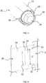
figure 2 , une vue de face du fût de la platine de lafigure 1 ; -
figure 3 , une vue partielle rapprochée d'un élément de blocage anti-rotation de la platine de lafigure 1 ; -
figure 4 , une vue partielle rapprochée d'une nervure de l'élément de blocage anti-rotation de lafigure 3 ; -
figure 5 , une forme de réalisation d'une colonne de direction selon l'invention ; -
figure 6 , une vue rapprochée de la liaison par encastrement entre un élément de blocage anti-rotation d'une platine et une colonne de direction selon l'invention.
-
figure 1 an embodiment of a platen according to the invention; -
figure 2 , a front view of the barrel of the platinum of thefigure 1 ; -
figure 3 , a partial partial view of an anti-rotation locking element of the plate of thefigure 1 ; -
figure 4 , a partial partial view of a rib of the anti-rotation locking element of thefigure 3 ; -
figure 5 an embodiment of a steering column according to the invention; -
figure 6 , a close-up view of the connection by embedding between an anti-rotation locking element of a plate and a steering column according to the invention.
Dans ce qui va suivre, la forme de réalisation décrite s'attache plus particulièrement à une mise en oeuvre de la platine selon l'invention à une colonne de direction d'un véhicule, notamment dans le domaine automobile. Cependant, toute mise en oeuvre dans un contexte différent, en vue d'assurer une fonction de blocage en rotation d'une platine sur un support tel qu'un bras, est également visée par la présente invention.In what follows, the embodiment described is more particularly related to an implementation of the plate according to the invention to a steering column of a vehicle, particularly in the automotive field. However, any implementation in a different context, in order to provide a rotational locking function of a plate on a support such as an arm, is also covered by the present invention.
La
La platine 1 peut être réalisée en tout matériau connu approprié. De préférence, la platine 1 est réalisée par moulage en matière plastique.The
La platine 1 peut supporter des organes actifs du commutateur électrique, notamment des lames électriquement conductrices.The
Dans la forme de réalisation illustrée par la
La platine 1 comprend un fût 2 s'étendant orthogonalement à la plaque 1a selon un axe X qui permet de fixer la platine 1 sur une colonne de direction 20 (en référence à la
A cette fin, le fût 2 est fendu axialement orthogonale à la plaque 1a. Le diamètre interne du fût fendu 2 au repos est adapté pour être engagé autour de la colonne de direction 20 du véhicule (non représenté) puis serré sur ladite colonne 20 à l'aide d'un collier de serrage 3 et d'un système de vis et d'écrou 4. Bien entendu, tous autres moyens de serrage pourraient être utilisés.For this purpose, the
Dans l'exemple illustré à la
Le deuxième élément annulaire 6 de diamètre inférieur au premier élément annulaire 5 défini une ouverture 7 agencée pour recevoir une portion (non représentée) de la colonne de direction 20.The second
Le premier élément annulaire 5 s'étend de la plaque 1a et comprend deux portions de support 8 s'étendant en saillie à l'intérieur du fût 2 parallèlement à l'axe X.The first
Selon l'invention, la platine 1 comprend dans cet exemple deux éléments de blocage anti-rotation 10 diamétralement opposées disposées à l'intérieur du fût 2.According to the invention, the
Chacun des deux éléments de blocage anti-rotation 10 se présente sous la forme d'une portion issue de matière de la platine 1 qui s'étend en saillie parallèlement à l'axe X du fût 2 entre l'une des portions de support 8 et le fût 2 depuis l'élément annulaire 5.Each of the two
Selon l'invention, les éléments de blocage anti-rotation 10 sont agencés chacun pour coopérer par encastrement avec une découpe 30 de la colonne de direction 20 (en référence aux
Ainsi, en tenant compte des éventuelles contraintes de structure et d'agencement, pour la fixation de la platine 1 sur la colonne de direction 20, une pluralité d'éléments de blocage anti-rotation 10 est prévue sur la platine 1 afin de la bloquer en rotation par rapport à la colonne 20.Thus, taking into account any structural and layout constraints, for fixing the
Dans l'exemple illustré, la section transversale des éléments de blocage anti-rotation 10 est sensiblement en arc de cercle d'une courbure dont la valeur est de l'ordre de celle de la découpe 30 de la colonne de direction 20 afin de permettre un encastrement solide.In the example illustrated, the cross section of the
Cela est notamment possible lorsque les éléments de blocage anti-rotation 10 sont réalisés lors du moulage de la platine 1 de manière connue de l'homme du métier. Toutefois, il va de soi qu'en variante, les éléments de blocage anti-rotation 10 peuvent être rapportés sur la platine 1.This is possible in particular when the
De préférence, chaque élément de blocage anti-rotation 10 comprend une portion réalisée en un matériau plastique déformable, par exemple de type PA6GF30 connu de l'homme du métier, de sorte à être déformé par matage lors de son encastrement dans la découpe 30 correspondante de la colonne de direction 20.Preferably, each
Dans l'exemple illustré aux
La largeur L1 de l'élément de blocage anti-rotation 10 au repos (i.e. avant encastrement) avec la nervure 12 est ainsi supérieure ou égale à la largeur L2 de la découpe 30 correspondante de la colonne de direction 20. Par exemple, la largeur L2 de la découpe 30 peut être de l'ordre de 12 mm et la largeur L1 de l'élément de blocage anti-rotation 10 au repos peut être de 12,225 mm, la nervure 12 ayant une épaisseur, par exemple, de 0,225 mm.The width L1 of the
L'utilisation d'une telle nervure 12 déformable facilite l'encastrement de l'élément de blocage anti-rotation 10 en force tout en assurant un maintien par encastrement solide dans la découpe 30. Il va de soi qu'un élément de blocage anti-rotation 10 peut comprendre plus d'une portion réalisée en un matériau déformable pour permettre son encastrement dans la découpe 30 correspondante. Par exemple, dans le cas d'une pluralité de nervures 12, ces nervures 12 peuvent être d'une épaisseur différente, par exemple plus petite que 12,225 mm de sorte à éviter d'avoir à exercer un effort d'encastrement trop important.The use of such a
Comme illustré par la
En référence à la
Ainsi, lors du montage de la platine 1 sur la colonne de direction 20, on positionne tout d'abord les éléments de blocage anti-rotation 10 face aux découpes 30 correspondantes de la colonne de direction 20.Thus, during the mounting of the
On insère ensuite en force par encastrement chacun des éléments de blocage anti-rotation 10 de la platine 1 dans la découpe 30 correspondante de la colonne de direction 20, les extrémités en biseau 32 des découpes facilitant l'insertion et l'encastrement et les nervures 12 se déformant lors de l'encastrement afin de maintenir solidement les éléments de blocage anti-rotation 10 encastrés dans les découpes 30.Then each of the
Une fois les éléments de blocage anti-rotation 10 encastrés dans les découpes 30, on serre le fût 2 autour de la colonne de direction 20 à l'aide des moyens de serrage 3 et 4.Once the
Il peut bien entendu être prévu, sans sortir du cadre de la présente invention, des éléments de blocage anti-rotation 10 et des découpes 30 de formes différentes tenant compte de la structure de la platine 1 et/ou de la structure de la colonne de direction 20.It may of course be provided, without departing from the scope of the present invention,
Il est à noter, en outre, que la présente invention n'est pas limitée aux exemples décrits ci-dessus et est susceptible de nombreuses variantes accessibles à l'homme de l'art. Notamment, la forme et les dimensions de la platine 1, du fût 3, des éléments de blocage anti-rotation 10, de la colonne de direction 20 et des découpes 30 tels que représentés sur les figures de façon à illustrer un exemple de réalisation de l'invention, ne sauraient être interprétés comme limitatifs.It should be noted, moreover, that the present invention is not limited to the examples described above and is capable of numerous variants accessible to those skilled in the art. In particular, the shape and dimensions of the
Claims (9)
- A plate intended to be mounted on a steering column (20) of a vehicle, said plate (1) including a sheet (1a) from which an axially split drum (2) capable of being mounted on said steering column (20) extends orthogonally, said plate (1) including a plurality of anti-rotation locking elements (10) each arranged so as to cooperate by fitting with a cut-out (30) of the steering column (20), characterized in that, the plate (1) including two anti-rotation locking elements (10), the two anti-rotation locking elements (10) are diametrically opposed with respect to the axis (X) of the drum (2).
- The plate according to the preceding claim, characterized in that the anti-rotation locking elements (10) extend projecting in the interior of the drum (2) parallel to its axis (X).
- The plate according to one of the preceding claims, characterized in that the anti-rotation locking elements (10) include at least one portion made from a deformable material and arranged so as to be deformed during the fitting of the anti-rotation locking element (10) in the corresponding cut-out (30) of the steering column (20).
- The plate according to the preceding claim, characterized in that said portion includes a rib (12) extending parallel to the axis (X) of the barrel (2).
- The plate according to one of the preceding claims, characterized in that the anti-rotation locking elements (10) are made from the material of the plate (1) .
- A steering column, characterized in that it includes a plurality of cut-outs (30) each arranged so as to receive, by fitting, an anti-rotation locking element (10) of a plate (1) according to one of the preceding claims.
- The steering column according to the preceding claim, characterized in that each of the cut-outs (30) is U-shaped, the ends (32) of which are bevelled, so as to facilitate the insertion and to permit the caulking of the corresponding anti-rotation locking element (10) of the plate (1).
- An assembly formed by a plate (1) according to one of Claims 1 to 5 and by a steering column according to one of Claims 6 and 7, characterized in that the anti-rotation locking elements (10) of the plate (1) are fitted in the corresponding cut-outs (30) of the steering column (20).
- A method for mounting an assembly according to Claim 8, said method being characterized in that it includes a step of press-in insertion by fitting of the anti-rotation locking elements (10) of the plate (1) in the corresponding cut-outs (30) of the steering column (20) .
Applications Claiming Priority (2)
| Application Number | Priority Date | Filing Date | Title |
|---|---|---|---|
| FR1361477A FR3013301B1 (en) | 2013-11-21 | 2013-11-21 | ELECTRIC SWITCH PLATE AND STEERING COLUMN OF A VEHICLE |
| PCT/FR2014/052810 WO2015075344A1 (en) | 2013-11-21 | 2014-11-05 | Plate of an electric switch and steering column of a vehicle |
Publications (2)
| Publication Number | Publication Date |
|---|---|
| EP3074294A1 EP3074294A1 (en) | 2016-10-05 |
| EP3074294B1 true EP3074294B1 (en) | 2018-10-24 |
Family
ID=50102017
Family Applications (1)
| Application Number | Title | Priority Date | Filing Date |
|---|---|---|---|
| EP14806010.6A Active EP3074294B1 (en) | 2013-11-21 | 2014-11-05 | Plate of an electric switch and steering column of a vehicle |
Country Status (4)
| Country | Link |
|---|---|
| EP (1) | EP3074294B1 (en) |
| CN (1) | CN105745137B (en) |
| FR (1) | FR3013301B1 (en) |
| WO (1) | WO2015075344A1 (en) |
Family Cites Families (6)
| Publication number | Priority date | Publication date | Assignee | Title |
|---|---|---|---|---|
| JPS58110336A (en) * | 1981-12-24 | 1983-06-30 | Nissan Motor Co Ltd | Switch box fixing structure |
| FR2702016B1 (en) * | 1993-02-24 | 1995-07-07 | Ecia Equip Composants Ind Auto | DEVICE FOR THE TEMPORARY IMMOBILIZATION OF TWO MOUNTED ORGANS MOVABLE ONE INTO THE OTHER, OF A STEERING COLUMN ASSEMBLY OF A MOTOR VEHICLE. |
| FR2833553B1 (en) * | 2001-12-13 | 2004-03-05 | Valeo Electronique | MODULE FOR TOP OF STEERING COLUMN AND ASSEMBLY PROVIDED WITH THIS MODULE |
| DE102004045876B4 (en) * | 2004-09-20 | 2006-07-06 | Delphi Technologies, Inc., Troy | Fastening device for a steering column module of a motor vehicle |
| FR2950850B1 (en) * | 2009-10-02 | 2012-01-13 | Renault Sa | SYSTEM FOR FASTENING A MODULE FOR HIGH COLUMN STEERING. |
| JP2012131420A (en) * | 2010-12-22 | 2012-07-12 | Jtekt Corp | Steering device for vehicle |
-
2013
- 2013-11-21 FR FR1361477A patent/FR3013301B1/en active Active
-
2014
- 2014-11-05 CN CN201480063505.0A patent/CN105745137B/en active Active
- 2014-11-05 WO PCT/FR2014/052810 patent/WO2015075344A1/en active Application Filing
- 2014-11-05 EP EP14806010.6A patent/EP3074294B1/en active Active
Non-Patent Citations (1)
| Title |
|---|
| None * |
Also Published As
| Publication number | Publication date |
|---|---|
| CN105745137B (en) | 2019-04-09 |
| FR3013301B1 (en) | 2017-02-17 |
| FR3013301A1 (en) | 2015-05-22 |
| EP3074294A1 (en) | 2016-10-05 |
| CN105745137A (en) | 2016-07-06 |
| WO2015075344A1 (en) | 2015-05-28 |
Similar Documents
| Publication | Publication Date | Title |
|---|---|---|
| EP0276613B1 (en) | Clutch release mechanism, especially for an automotive vehicle | |
| FR2781259A1 (en) | Fitting of hydraulic master cylinder for operating brake or clutch mechanisms in motor vehicles which uses a self locking bayonet fixing | |
| FR3011139A1 (en) | ELECTRICAL ENCLOSURE BOX | |
| EP3074294B1 (en) | Plate of an electric switch and steering column of a vehicle | |
| FR2956910A1 (en) | Pedal e.g. footbrake pedal, for use in sports type motor vehicle, has core articulated with respect to body shell of vehicle, and fixing units cooperating with opposite edges of track shoe aligned along main direction of pedal | |
| EP1060555A1 (en) | Motor vehicle alternator rotor with interposed permanent magnets | |
| EP4011714B1 (en) | Device for attaching a buckle for seatbelt | |
| WO2011061426A1 (en) | Windshield wiper provided with a mounting plate | |
| EP3658790B1 (en) | Nut cage system comprising a nut cage and a support on which the cage is intended to be mounted | |
| EP3375675B1 (en) | Cap, connecting device for mounting a windscreen wiper on a corresponding windscreen wiper arm and windscreen wiping system | |
| EP4028292A1 (en) | Crank pin, ball joint and corresponding wiper actuating linkage system and method for the assembly thereof | |
| FR2928982A1 (en) | Friction part for motor vehicle, has unitary washer with friction tongues that are in contact with element, and maintaining unit maintaining part in position with respect to receiving element and element | |
| EP1751435A1 (en) | Motor vehicle accessory | |
| EP2665629B1 (en) | Windshield wiper device for motor vehicle | |
| FR3056948B1 (en) | ELECTRICAL CONTROL BLOCK FOR DOOR TRIM | |
| WO2022171832A1 (en) | Adapter for a wiping system | |
| FR3013274A1 (en) | FIXING A PLATINUM ON A COLUMN | |
| EP4051909B1 (en) | Motor support and hvac (heating, ventilating and/or airconditioning) device for automobile vehicle | |
| EP2234861B1 (en) | Assembly for mounting a steering wheel on the steering column of an automobile | |
| EP3233586B1 (en) | Steering column lock | |
| WO2023208726A1 (en) | Wiper system connection assembly | |
| FR3034476A1 (en) | PERFECTED MATT PLATE FOR SCREW ASSEMBLY | |
| FR2715617A1 (en) | Vehicle headlamp, comprising improved means for mounting a corrector of the inclination of the reflector. | |
| EP4078782A1 (en) | Motor for a ventilation device of a heating, ventilation and/or air conditioning system of a motor vehicle with a rotor and stator decoupled from a mounting base | |
| FR3003786A1 (en) | ATTACHMENT TOOL FOR ASSEMBLING TWO FLANGES WITH POSITIONING ELEMENT PREVENTING THE ROTATION OF FLANGES |
Legal Events
| Date | Code | Title | Description |
|---|---|---|---|
| PUAI | Public reference made under article 153(3) epc to a published international application that has entered the european phase |
Free format text: ORIGINAL CODE: 0009012 |
|
| 17P | Request for examination filed |
Effective date: 20160614 |
|
| AK | Designated contracting states |
Kind code of ref document: A1 Designated state(s): AL AT BE BG CH CY CZ DE DK EE ES FI FR GB GR HR HU IE IS IT LI LT LU LV MC MK MT NL NO PL PT RO RS SE SI SK SM TR |
|
| AX | Request for extension of the european patent |
Extension state: BA ME |
|
| DAX | Request for extension of the european patent (deleted) | ||
| RAP1 | Party data changed (applicant data changed or rights of an application transferred) |
Owner name: PSA AUTOMOBILES SA |
|
| GRAP | Despatch of communication of intention to grant a patent |
Free format text: ORIGINAL CODE: EPIDOSNIGR1 |
|
| INTG | Intention to grant announced |
Effective date: 20180531 |
|
| GRAS | Grant fee paid |
Free format text: ORIGINAL CODE: EPIDOSNIGR3 |
|
| GRAA | (expected) grant |
Free format text: ORIGINAL CODE: 0009210 |
|
| AK | Designated contracting states |
Kind code of ref document: B1 Designated state(s): AL AT BE BG CH CY CZ DE DK EE ES FI FR GB GR HR HU IE IS IT LI LT LU LV MC MK MT NL NO PL PT RO RS SE SI SK SM TR |
|
| REG | Reference to a national code |
Ref country code: CH Ref legal event code: EP |
|
| REG | Reference to a national code |
Ref country code: IE Ref legal event code: FG4D Free format text: LANGUAGE OF EP DOCUMENT: FRENCH |
|
| REG | Reference to a national code |
Ref country code: AT Ref legal event code: REF Ref document number: 1056328 Country of ref document: AT Kind code of ref document: T Effective date: 20181115 |
|
| REG | Reference to a national code |
Ref country code: DE Ref legal event code: R096 Ref document number: 602014034766 Country of ref document: DE |
|
| REG | Reference to a national code |
Ref country code: NL Ref legal event code: MP Effective date: 20181024 |
|
| REG | Reference to a national code |
Ref country code: LT Ref legal event code: MG4D |
|
| REG | Reference to a national code |
Ref country code: AT Ref legal event code: MK05 Ref document number: 1056328 Country of ref document: AT Kind code of ref document: T Effective date: 20181024 |
|
| PG25 | Lapsed in a contracting state [announced via postgrant information from national office to epo] |
Ref country code: NL Free format text: LAPSE BECAUSE OF FAILURE TO SUBMIT A TRANSLATION OF THE DESCRIPTION OR TO PAY THE FEE WITHIN THE PRESCRIBED TIME-LIMIT Effective date: 20181024 |
|
| PG25 | Lapsed in a contracting state [announced via postgrant information from national office to epo] |
Ref country code: ES Free format text: LAPSE BECAUSE OF FAILURE TO SUBMIT A TRANSLATION OF THE DESCRIPTION OR TO PAY THE FEE WITHIN THE PRESCRIBED TIME-LIMIT Effective date: 20181024 Ref country code: LV Free format text: LAPSE BECAUSE OF FAILURE TO SUBMIT A TRANSLATION OF THE DESCRIPTION OR TO PAY THE FEE WITHIN THE PRESCRIBED TIME-LIMIT Effective date: 20181024 Ref country code: AT Free format text: LAPSE BECAUSE OF FAILURE TO SUBMIT A TRANSLATION OF THE DESCRIPTION OR TO PAY THE FEE WITHIN THE PRESCRIBED TIME-LIMIT Effective date: 20181024 Ref country code: FI Free format text: LAPSE BECAUSE OF FAILURE TO SUBMIT A TRANSLATION OF THE DESCRIPTION OR TO PAY THE FEE WITHIN THE PRESCRIBED TIME-LIMIT Effective date: 20181024 Ref country code: IS Free format text: LAPSE BECAUSE OF FAILURE TO SUBMIT A TRANSLATION OF THE DESCRIPTION OR TO PAY THE FEE WITHIN THE PRESCRIBED TIME-LIMIT Effective date: 20190224 Ref country code: NO Free format text: LAPSE BECAUSE OF FAILURE TO SUBMIT A TRANSLATION OF THE DESCRIPTION OR TO PAY THE FEE WITHIN THE PRESCRIBED TIME-LIMIT Effective date: 20190124 Ref country code: HR Free format text: LAPSE BECAUSE OF FAILURE TO SUBMIT A TRANSLATION OF THE DESCRIPTION OR TO PAY THE FEE WITHIN THE PRESCRIBED TIME-LIMIT Effective date: 20181024 Ref country code: PL Free format text: LAPSE BECAUSE OF FAILURE TO SUBMIT A TRANSLATION OF THE DESCRIPTION OR TO PAY THE FEE WITHIN THE PRESCRIBED TIME-LIMIT Effective date: 20181024 Ref country code: BG Free format text: LAPSE BECAUSE OF FAILURE TO SUBMIT A TRANSLATION OF THE DESCRIPTION OR TO PAY THE FEE WITHIN THE PRESCRIBED TIME-LIMIT Effective date: 20190124 Ref country code: LT Free format text: LAPSE BECAUSE OF FAILURE TO SUBMIT A TRANSLATION OF THE DESCRIPTION OR TO PAY THE FEE WITHIN THE PRESCRIBED TIME-LIMIT Effective date: 20181024 |
|
| PG25 | Lapsed in a contracting state [announced via postgrant information from national office to epo] |
Ref country code: RS Free format text: LAPSE BECAUSE OF FAILURE TO SUBMIT A TRANSLATION OF THE DESCRIPTION OR TO PAY THE FEE WITHIN THE PRESCRIBED TIME-LIMIT Effective date: 20181024 Ref country code: SE Free format text: LAPSE BECAUSE OF FAILURE TO SUBMIT A TRANSLATION OF THE DESCRIPTION OR TO PAY THE FEE WITHIN THE PRESCRIBED TIME-LIMIT Effective date: 20181024 Ref country code: GR Free format text: LAPSE BECAUSE OF FAILURE TO SUBMIT A TRANSLATION OF THE DESCRIPTION OR TO PAY THE FEE WITHIN THE PRESCRIBED TIME-LIMIT Effective date: 20190125 Ref country code: PT Free format text: LAPSE BECAUSE OF FAILURE TO SUBMIT A TRANSLATION OF THE DESCRIPTION OR TO PAY THE FEE WITHIN THE PRESCRIBED TIME-LIMIT Effective date: 20190224 Ref country code: AL Free format text: LAPSE BECAUSE OF FAILURE TO SUBMIT A TRANSLATION OF THE DESCRIPTION OR TO PAY THE FEE WITHIN THE PRESCRIBED TIME-LIMIT Effective date: 20181024 |
|
| REG | Reference to a national code |
Ref country code: DE Ref legal event code: R084 Ref document number: 602014034766 Country of ref document: DE |
|
| REG | Reference to a national code |
Ref country code: CH Ref legal event code: PL |
|
| REG | Reference to a national code |
Ref country code: GB Ref legal event code: 746 Effective date: 20190618 |
|
| REG | Reference to a national code |
Ref country code: DE Ref legal event code: R097 Ref document number: 602014034766 Country of ref document: DE |
|
| PG25 | Lapsed in a contracting state [announced via postgrant information from national office to epo] |
Ref country code: LU Free format text: LAPSE BECAUSE OF NON-PAYMENT OF DUE FEES Effective date: 20181105 Ref country code: CZ Free format text: LAPSE BECAUSE OF FAILURE TO SUBMIT A TRANSLATION OF THE DESCRIPTION OR TO PAY THE FEE WITHIN THE PRESCRIBED TIME-LIMIT Effective date: 20181024 Ref country code: IT Free format text: LAPSE BECAUSE OF FAILURE TO SUBMIT A TRANSLATION OF THE DESCRIPTION OR TO PAY THE FEE WITHIN THE PRESCRIBED TIME-LIMIT Effective date: 20181024 Ref country code: DK Free format text: LAPSE BECAUSE OF FAILURE TO SUBMIT A TRANSLATION OF THE DESCRIPTION OR TO PAY THE FEE WITHIN THE PRESCRIBED TIME-LIMIT Effective date: 20181024 |
|
| REG | Reference to a national code |
Ref country code: BE Ref legal event code: MM Effective date: 20181130 |
|
| REG | Reference to a national code |
Ref country code: IE Ref legal event code: MM4A |
|
| PG25 | Lapsed in a contracting state [announced via postgrant information from national office to epo] |
Ref country code: RO Free format text: LAPSE BECAUSE OF FAILURE TO SUBMIT A TRANSLATION OF THE DESCRIPTION OR TO PAY THE FEE WITHIN THE PRESCRIBED TIME-LIMIT Effective date: 20181024 Ref country code: SK Free format text: LAPSE BECAUSE OF FAILURE TO SUBMIT A TRANSLATION OF THE DESCRIPTION OR TO PAY THE FEE WITHIN THE PRESCRIBED TIME-LIMIT Effective date: 20181024 Ref country code: SM Free format text: LAPSE BECAUSE OF FAILURE TO SUBMIT A TRANSLATION OF THE DESCRIPTION OR TO PAY THE FEE WITHIN THE PRESCRIBED TIME-LIMIT Effective date: 20181024 Ref country code: CH Free format text: LAPSE BECAUSE OF NON-PAYMENT OF DUE FEES Effective date: 20181130 Ref country code: EE Free format text: LAPSE BECAUSE OF FAILURE TO SUBMIT A TRANSLATION OF THE DESCRIPTION OR TO PAY THE FEE WITHIN THE PRESCRIBED TIME-LIMIT Effective date: 20181024 Ref country code: LI Free format text: LAPSE BECAUSE OF NON-PAYMENT OF DUE FEES Effective date: 20181130 Ref country code: MC Free format text: LAPSE BECAUSE OF FAILURE TO SUBMIT A TRANSLATION OF THE DESCRIPTION OR TO PAY THE FEE WITHIN THE PRESCRIBED TIME-LIMIT Effective date: 20181024 |
|
| PLBE | No opposition filed within time limit |
Free format text: ORIGINAL CODE: 0009261 |
|
| STAA | Information on the status of an ep patent application or granted ep patent |
Free format text: STATUS: NO OPPOSITION FILED WITHIN TIME LIMIT |
|
| 26N | No opposition filed |
Effective date: 20190725 |
|
| PG25 | Lapsed in a contracting state [announced via postgrant information from national office to epo] |
Ref country code: IE Free format text: LAPSE BECAUSE OF NON-PAYMENT OF DUE FEES Effective date: 20181105 Ref country code: SI Free format text: LAPSE BECAUSE OF FAILURE TO SUBMIT A TRANSLATION OF THE DESCRIPTION OR TO PAY THE FEE WITHIN THE PRESCRIBED TIME-LIMIT Effective date: 20181024 |
|
| PG25 | Lapsed in a contracting state [announced via postgrant information from national office to epo] |
Ref country code: BE Free format text: LAPSE BECAUSE OF NON-PAYMENT OF DUE FEES Effective date: 20181130 |
|
| PG25 | Lapsed in a contracting state [announced via postgrant information from national office to epo] |
Ref country code: MT Free format text: LAPSE BECAUSE OF FAILURE TO SUBMIT A TRANSLATION OF THE DESCRIPTION OR TO PAY THE FEE WITHIN THE PRESCRIBED TIME-LIMIT Effective date: 20181024 |
|
| PG25 | Lapsed in a contracting state [announced via postgrant information from national office to epo] |
Ref country code: TR Free format text: LAPSE BECAUSE OF FAILURE TO SUBMIT A TRANSLATION OF THE DESCRIPTION OR TO PAY THE FEE WITHIN THE PRESCRIBED TIME-LIMIT Effective date: 20181024 |
|
| PG25 | Lapsed in a contracting state [announced via postgrant information from national office to epo] |
Ref country code: MK Free format text: LAPSE BECAUSE OF NON-PAYMENT OF DUE FEES Effective date: 20181024 Ref country code: HU Free format text: LAPSE BECAUSE OF FAILURE TO SUBMIT A TRANSLATION OF THE DESCRIPTION OR TO PAY THE FEE WITHIN THE PRESCRIBED TIME-LIMIT; INVALID AB INITIO Effective date: 20141105 Ref country code: CY Free format text: LAPSE BECAUSE OF FAILURE TO SUBMIT A TRANSLATION OF THE DESCRIPTION OR TO PAY THE FEE WITHIN THE PRESCRIBED TIME-LIMIT Effective date: 20181024 |
|
| PGFP | Annual fee paid to national office [announced via postgrant information from national office to epo] |
Ref country code: GB Payment date: 20231019 Year of fee payment: 10 |
|
| PGFP | Annual fee paid to national office [announced via postgrant information from national office to epo] |
Ref country code: FR Payment date: 20231019 Year of fee payment: 10 Ref country code: DE Payment date: 20231019 Year of fee payment: 10 |