EP3074079B1 - Dispositifs medicaux permettant d'acceder a des lumieres corporelles - Google Patents
Dispositifs medicaux permettant d'acceder a des lumieres corporelles Download PDFInfo
- Publication number
- EP3074079B1 EP3074079B1 EP14808795.0A EP14808795A EP3074079B1 EP 3074079 B1 EP3074079 B1 EP 3074079B1 EP 14808795 A EP14808795 A EP 14808795A EP 3074079 B1 EP3074079 B1 EP 3074079B1
- Authority
- EP
- European Patent Office
- Prior art keywords
- guidewire
- constant diameter
- distal
- diameter section
- core wire
- Prior art date
- Legal status (The legal status is an assumption and is not a legal conclusion. Google has not performed a legal analysis and makes no representation as to the accuracy of the status listed.)
- Active
Links
- 229910001000 nickel titanium Inorganic materials 0.000 claims description 26
- 239000000463 material Substances 0.000 claims description 23
- 208000012287 Prolapse Diseases 0.000 claims description 7
- HLXZNVUGXRDIFK-UHFFFAOYSA-N nickel titanium Chemical compound [Ti].[Ti].[Ti].[Ti].[Ti].[Ti].[Ti].[Ti].[Ti].[Ti].[Ti].[Ni].[Ni].[Ni].[Ni].[Ni].[Ni].[Ni].[Ni].[Ni].[Ni].[Ni].[Ni].[Ni].[Ni] HLXZNVUGXRDIFK-UHFFFAOYSA-N 0.000 description 16
- 238000000034 method Methods 0.000 description 14
- -1 polytetrafluoroethylene Polymers 0.000 description 10
- 229910001182 Mo alloy Inorganic materials 0.000 description 7
- 229910045601 alloy Inorganic materials 0.000 description 7
- 239000000956 alloy Substances 0.000 description 7
- 238000003780 insertion Methods 0.000 description 6
- 230000037431 insertion Effects 0.000 description 6
- 239000000203 mixture Substances 0.000 description 6
- 230000007704 transition Effects 0.000 description 5
- PXHVJJICTQNCMI-UHFFFAOYSA-N Nickel Chemical compound [Ni] PXHVJJICTQNCMI-UHFFFAOYSA-N 0.000 description 4
- 210000003484 anatomy Anatomy 0.000 description 4
- 210000001953 common bile duct Anatomy 0.000 description 4
- 229910000856 hastalloy Inorganic materials 0.000 description 4
- 238000004519 manufacturing process Methods 0.000 description 4
- BASFCYQUMIYNBI-UHFFFAOYSA-N platinum Chemical compound [Pt] BASFCYQUMIYNBI-UHFFFAOYSA-N 0.000 description 4
- 229920000642 polymer Polymers 0.000 description 4
- 239000010935 stainless steel Substances 0.000 description 4
- 229910001220 stainless steel Inorganic materials 0.000 description 4
- RTZKZFJDLAIYFH-UHFFFAOYSA-N Diethyl ether Chemical compound CCOCC RTZKZFJDLAIYFH-UHFFFAOYSA-N 0.000 description 3
- 229920000106 Liquid crystal polymer Polymers 0.000 description 3
- 239000004977 Liquid-crystal polymers (LCPs) Substances 0.000 description 3
- 239000004952 Polyamide Substances 0.000 description 3
- 229920002614 Polyether block amide Polymers 0.000 description 3
- 239000004721 Polyphenylene oxide Substances 0.000 description 3
- 230000006870 function Effects 0.000 description 3
- 238000002595 magnetic resonance imaging Methods 0.000 description 3
- 229910052751 metal Inorganic materials 0.000 description 3
- 239000002184 metal Substances 0.000 description 3
- 210000000277 pancreatic duct Anatomy 0.000 description 3
- 229920002647 polyamide Polymers 0.000 description 3
- 238000003466 welding Methods 0.000 description 3
- 229910000881 Cu alloy Inorganic materials 0.000 description 2
- 239000004812 Fluorinated ethylene propylene Substances 0.000 description 2
- 229920000339 Marlex Polymers 0.000 description 2
- KDLHZDBZIXYQEI-UHFFFAOYSA-N Palladium Chemical compound [Pd] KDLHZDBZIXYQEI-UHFFFAOYSA-N 0.000 description 2
- 239000004696 Poly ether ether ketone Substances 0.000 description 2
- 239000004697 Polyetherimide Substances 0.000 description 2
- 239000004698 Polyethylene Substances 0.000 description 2
- 239000004642 Polyimide Substances 0.000 description 2
- 239000004734 Polyphenylene sulfide Substances 0.000 description 2
- 239000004743 Polypropylene Substances 0.000 description 2
- RTAQQCXQSZGOHL-UHFFFAOYSA-N Titanium Chemical compound [Ti] RTAQQCXQSZGOHL-UHFFFAOYSA-N 0.000 description 2
- 229910001080 W alloy Inorganic materials 0.000 description 2
- MTHLBYMFGWSRME-UHFFFAOYSA-N [Cr].[Co].[Mo] Chemical compound [Cr].[Co].[Mo] MTHLBYMFGWSRME-UHFFFAOYSA-N 0.000 description 2
- HZEWFHLRYVTOIW-UHFFFAOYSA-N [Ti].[Ni] Chemical compound [Ti].[Ni] HZEWFHLRYVTOIW-UHFFFAOYSA-N 0.000 description 2
- 238000004458 analytical method Methods 0.000 description 2
- 229910001566 austenite Inorganic materials 0.000 description 2
- 238000005452 bending Methods 0.000 description 2
- 210000003445 biliary tract Anatomy 0.000 description 2
- 238000005219 brazing Methods 0.000 description 2
- 239000000788 chromium alloy Substances 0.000 description 2
- PRQRQKBNBXPISG-UHFFFAOYSA-N chromium cobalt molybdenum nickel Chemical compound [Cr].[Co].[Ni].[Mo] PRQRQKBNBXPISG-UHFFFAOYSA-N 0.000 description 2
- 239000002131 composite material Substances 0.000 description 2
- 229920001577 copolymer Polymers 0.000 description 2
- YOCUPQPZWBBYIX-UHFFFAOYSA-N copper nickel Chemical compound [Ni].[Cu] YOCUPQPZWBBYIX-UHFFFAOYSA-N 0.000 description 2
- 238000000113 differential scanning calorimetry Methods 0.000 description 2
- 229910000701 elgiloys (Co-Cr-Ni Alloy) Inorganic materials 0.000 description 2
- 150000002148 esters Chemical class 0.000 description 2
- 229920000840 ethylene tetrafluoroethylene copolymer Polymers 0.000 description 2
- 229910000734 martensite Inorganic materials 0.000 description 2
- 229910001092 metal group alloy Inorganic materials 0.000 description 2
- 150000002739 metals Chemical class 0.000 description 2
- DDTIGTPWGISMKL-UHFFFAOYSA-N molybdenum nickel Chemical compound [Ni].[Mo] DDTIGTPWGISMKL-UHFFFAOYSA-N 0.000 description 2
- 229910052759 nickel Inorganic materials 0.000 description 2
- 229920009441 perflouroethylene propylene Polymers 0.000 description 2
- 229910052697 platinum Inorganic materials 0.000 description 2
- 229920001200 poly(ethylene-vinyl acetate) Polymers 0.000 description 2
- 229920001707 polybutylene terephthalate Polymers 0.000 description 2
- 229920000728 polyester Polymers 0.000 description 2
- 229920002530 polyetherether ketone Polymers 0.000 description 2
- 229920001601 polyetherimide Polymers 0.000 description 2
- 229920000573 polyethylene Polymers 0.000 description 2
- 229920000139 polyethylene terephthalate Polymers 0.000 description 2
- 239000005020 polyethylene terephthalate Substances 0.000 description 2
- 229920001721 polyimide Polymers 0.000 description 2
- 229920006324 polyoxymethylene Polymers 0.000 description 2
- 229920006380 polyphenylene oxide Polymers 0.000 description 2
- 229920000069 polyphenylene sulfide Polymers 0.000 description 2
- 229920001155 polypropylene Polymers 0.000 description 2
- 229920001343 polytetrafluoroethylene Polymers 0.000 description 2
- 239000004810 polytetrafluoroethylene Substances 0.000 description 2
- 229920002635 polyurethane Polymers 0.000 description 2
- 239000004814 polyurethane Substances 0.000 description 2
- 239000010936 titanium Substances 0.000 description 2
- 229910052719 titanium Inorganic materials 0.000 description 2
- KHXKESCWFMPTFT-UHFFFAOYSA-N 1,1,1,2,2,3,3-heptafluoro-3-(1,2,2-trifluoroethenoxy)propane Chemical compound FC(F)=C(F)OC(F)(F)C(F)(F)C(F)(F)F KHXKESCWFMPTFT-UHFFFAOYSA-N 0.000 description 1
- 229910000531 Co alloy Inorganic materials 0.000 description 1
- 229920004943 Delrin® Polymers 0.000 description 1
- 229920006055 Durethan® Polymers 0.000 description 1
- 239000004593 Epoxy Substances 0.000 description 1
- 229920000219 Ethylene vinyl alcohol Polymers 0.000 description 1
- 229910000640 Fe alloy Inorganic materials 0.000 description 1
- 229920003620 Grilon® Polymers 0.000 description 1
- 229920000271 Kevlar® Polymers 0.000 description 1
- JHWNWJKBPDFINM-UHFFFAOYSA-N Laurolactam Chemical compound O=C1CCCCCCCCCCCN1 JHWNWJKBPDFINM-UHFFFAOYSA-N 0.000 description 1
- 229910001209 Low-carbon steel Inorganic materials 0.000 description 1
- 229910000792 Monel Inorganic materials 0.000 description 1
- 229910000990 Ni alloy Inorganic materials 0.000 description 1
- 239000004677 Nylon Substances 0.000 description 1
- 229920000299 Nylon 12 Polymers 0.000 description 1
- 229930040373 Paraformaldehyde Natural products 0.000 description 1
- 229920000265 Polyparaphenylene Polymers 0.000 description 1
- 239000004793 Polystyrene Substances 0.000 description 1
- QXZUUHYBWMWJHK-UHFFFAOYSA-N [Co].[Ni] Chemical compound [Co].[Ni] QXZUUHYBWMWJHK-UHFFFAOYSA-N 0.000 description 1
- 239000000853 adhesive Substances 0.000 description 1
- 238000004026 adhesive bonding Methods 0.000 description 1
- 230000001070 adhesive effect Effects 0.000 description 1
- 210000000013 bile duct Anatomy 0.000 description 1
- 229920000249 biocompatible polymer Polymers 0.000 description 1
- 210000004204 blood vessel Anatomy 0.000 description 1
- 230000036760 body temperature Effects 0.000 description 1
- 239000000919 ceramic Substances 0.000 description 1
- OGSYQYXYGXIQFH-UHFFFAOYSA-N chromium molybdenum nickel Chemical compound [Cr].[Ni].[Mo] OGSYQYXYGXIQFH-UHFFFAOYSA-N 0.000 description 1
- 238000005520 cutting process Methods 0.000 description 1
- 230000003247 decreasing effect Effects 0.000 description 1
- 230000009977 dual effect Effects 0.000 description 1
- 210000001198 duodenum Anatomy 0.000 description 1
- 230000000694 effects Effects 0.000 description 1
- 239000013013 elastic material Substances 0.000 description 1
- 229920001971 elastomer Polymers 0.000 description 1
- 239000000806 elastomer Substances 0.000 description 1
- 229920006351 engineering plastic Polymers 0.000 description 1
- JBKVHLHDHHXQEQ-UHFFFAOYSA-N epsilon-caprolactam Chemical compound O=C1CCCCCN1 JBKVHLHDHHXQEQ-UHFFFAOYSA-N 0.000 description 1
- QHSJIZLJUFMIFP-UHFFFAOYSA-N ethene;1,1,2,2-tetrafluoroethene Chemical group C=C.FC(F)=C(F)F QHSJIZLJUFMIFP-UHFFFAOYSA-N 0.000 description 1
- HQQADJVZYDDRJT-UHFFFAOYSA-N ethene;prop-1-ene Chemical group C=C.CC=C HQQADJVZYDDRJT-UHFFFAOYSA-N 0.000 description 1
- 150000002170 ethers Chemical class 0.000 description 1
- 239000005038 ethylene vinyl acetate Substances 0.000 description 1
- 239000004715 ethylene vinyl alcohol Substances 0.000 description 1
- 239000003302 ferromagnetic material Substances 0.000 description 1
- 239000000945 filler Substances 0.000 description 1
- 238000002594 fluoroscopy Methods 0.000 description 1
- PCHJSUWPFVWCPO-UHFFFAOYSA-N gold Chemical compound [Au] PCHJSUWPFVWCPO-UHFFFAOYSA-N 0.000 description 1
- 229910052737 gold Inorganic materials 0.000 description 1
- 239000010931 gold Substances 0.000 description 1
- RZXDTJIXPSCHCI-UHFFFAOYSA-N hexa-1,5-diene-2,5-diol Chemical compound OC(=C)CCC(O)=C RZXDTJIXPSCHCI-UHFFFAOYSA-N 0.000 description 1
- 229920001903 high density polyethylene Polymers 0.000 description 1
- 239000004700 high-density polyethylene Substances 0.000 description 1
- 238000003384 imaging method Methods 0.000 description 1
- 229910001026 inconel Inorganic materials 0.000 description 1
- 208000014674 injury Diseases 0.000 description 1
- 229920000554 ionomer Polymers 0.000 description 1
- UGKDIUIOSMUOAW-UHFFFAOYSA-N iron nickel Chemical compound [Fe].[Ni] UGKDIUIOSMUOAW-UHFFFAOYSA-N 0.000 description 1
- 229920000092 linear low density polyethylene Polymers 0.000 description 1
- 239000004707 linear low-density polyethylene Substances 0.000 description 1
- 229920001684 low density polyethylene Polymers 0.000 description 1
- 239000004702 low-density polyethylene Substances 0.000 description 1
- 239000003550 marker Substances 0.000 description 1
- 239000002905 metal composite material Substances 0.000 description 1
- 238000012986 modification Methods 0.000 description 1
- 230000004048 modification Effects 0.000 description 1
- MOWMLACGTDMJRV-UHFFFAOYSA-N nickel tungsten Chemical compound [Ni].[W] MOWMLACGTDMJRV-UHFFFAOYSA-N 0.000 description 1
- 229910000623 nickel–chromium alloy Inorganic materials 0.000 description 1
- 229920001778 nylon Polymers 0.000 description 1
- 229910052763 palladium Inorganic materials 0.000 description 1
- VPRUMANMDWQMNF-UHFFFAOYSA-N phenylethane boronic acid Chemical compound OB(O)CCC1=CC=CC=C1 VPRUMANMDWQMNF-UHFFFAOYSA-N 0.000 description 1
- XNGIFLGASWRNHJ-UHFFFAOYSA-L phthalate(2-) Chemical compound [O-]C(=O)C1=CC=CC=C1C([O-])=O XNGIFLGASWRNHJ-UHFFFAOYSA-L 0.000 description 1
- 229920003023 plastic Polymers 0.000 description 1
- 239000004033 plastic Substances 0.000 description 1
- 229920002492 poly(sulfone) Polymers 0.000 description 1
- 239000004417 polycarbonate Substances 0.000 description 1
- 229920000515 polycarbonate Polymers 0.000 description 1
- 229920000570 polyether Polymers 0.000 description 1
- 239000011112 polyethylene naphthalate Substances 0.000 description 1
- 239000002861 polymer material Substances 0.000 description 1
- 229920000098 polyolefin Polymers 0.000 description 1
- 229920001296 polysiloxane Polymers 0.000 description 1
- 229920002223 polystyrene Polymers 0.000 description 1
- 229920002215 polytrimethylene terephthalate Polymers 0.000 description 1
- 239000004800 polyvinyl chloride Substances 0.000 description 1
- 239000005033 polyvinylidene chloride Substances 0.000 description 1
- 238000001556 precipitation Methods 0.000 description 1
- 238000005476 soldering Methods 0.000 description 1
- 229910052715 tantalum Inorganic materials 0.000 description 1
- GUVRBAGPIYLISA-UHFFFAOYSA-N tantalum atom Chemical compound [Ta] GUVRBAGPIYLISA-UHFFFAOYSA-N 0.000 description 1
- MHSKRLJMQQNJNC-UHFFFAOYSA-N terephthalamide Chemical compound NC(=O)C1=CC=C(C(N)=O)C=C1 MHSKRLJMQQNJNC-UHFFFAOYSA-N 0.000 description 1
- 125000000383 tetramethylene group Chemical group [H]C([H])([*:1])C([H])([H])C([H])([H])C([H])([H])[*:2] 0.000 description 1
- 230000001225 therapeutic effect Effects 0.000 description 1
- 238000002076 thermal analysis method Methods 0.000 description 1
- 230000008733 trauma Effects 0.000 description 1
- WFKWXMTUELFFGS-UHFFFAOYSA-N tungsten Chemical compound [W] WFKWXMTUELFFGS-UHFFFAOYSA-N 0.000 description 1
- 229910052721 tungsten Inorganic materials 0.000 description 1
- 239000010937 tungsten Substances 0.000 description 1
- 230000002792 vascular Effects 0.000 description 1
Images


Classifications
-
- A—HUMAN NECESSITIES
- A61—MEDICAL OR VETERINARY SCIENCE; HYGIENE
- A61M—DEVICES FOR INTRODUCING MEDIA INTO, OR ONTO, THE BODY; DEVICES FOR TRANSDUCING BODY MEDIA OR FOR TAKING MEDIA FROM THE BODY; DEVICES FOR PRODUCING OR ENDING SLEEP OR STUPOR
- A61M25/00—Catheters; Hollow probes
- A61M25/01—Introducing, guiding, advancing, emplacing or holding catheters
- A61M25/09—Guide wires
- A61M2025/09058—Basic structures of guide wires
- A61M2025/09075—Basic structures of guide wires having a core without a coil possibly combined with a sheath
-
- A—HUMAN NECESSITIES
- A61—MEDICAL OR VETERINARY SCIENCE; HYGIENE
- A61M—DEVICES FOR INTRODUCING MEDIA INTO, OR ONTO, THE BODY; DEVICES FOR TRANSDUCING BODY MEDIA OR FOR TAKING MEDIA FROM THE BODY; DEVICES FOR PRODUCING OR ENDING SLEEP OR STUPOR
- A61M25/00—Catheters; Hollow probes
- A61M25/01—Introducing, guiding, advancing, emplacing or holding catheters
- A61M25/09—Guide wires
- A61M2025/09133—Guide wires having specific material compositions or coatings; Materials with specific mechanical behaviours, e.g. stiffness, strength to transmit torque
-
- A—HUMAN NECESSITIES
- A61—MEDICAL OR VETERINARY SCIENCE; HYGIENE
- A61M—DEVICES FOR INTRODUCING MEDIA INTO, OR ONTO, THE BODY; DEVICES FOR TRANSDUCING BODY MEDIA OR FOR TAKING MEDIA FROM THE BODY; DEVICES FOR PRODUCING OR ENDING SLEEP OR STUPOR
- A61M25/00—Catheters; Hollow probes
- A61M25/01—Introducing, guiding, advancing, emplacing or holding catheters
- A61M25/09—Guide wires
- A61M2025/09175—Guide wires having specific characteristics at the distal tip
Definitions
- the present disclosure pertains to medical devices, and methods for manufacturing medical devices. More particularly, the present disclosure pertains to medical device for accessing body lumens.
- intracorporeal medical devices have been developed for medical use, for example, intravascular use. Some of these devices include guidewires, catheters, and the like. These devices are manufactured by any one of a variety of different manufacturing methods and may be used according to any one of a variety of methods. Of the known medical devices and methods, each has certain advantages and disadvantages. There is an ongoing need to provide alternative medical devices as well as alternative methods for manufacturing and using medical devices.
- US 2006/0089568 A1 discloses a guidewire for medical use such as in vascular and nonvascular systems.
- the distal end of the guidewire is of a smaller diameter and softer than the proximal end and fitted with a coil for springiness such that the distal end will bend when encountering curves in the body passageways.
- the distal end may also be tapered to provide an additional gradient of softness.
- US 7 717 864 B1 discloses a guidewire that is formed, at least in part, of a composite elongate core formed, at least in part, of precipitation hardened material.
- US 5 916 178 A discloses a guidewire for use in a catheter comprising a unitary core wire, a distal tip and an elongate tube.
- the core wire has a body segment and a transition segment, the body segment being of substantially uniform outer diameter with a distal end serially disposed proximal to the transition segment proximal end, the transition segment being more flexible than the body segment, and progressively reduced in cross-section from the body segment.
- US 2013/0110000 A1 discloses a dual diameter guide wire.
- a medical guide wire according to the invention is defined by the features of claim 1.
- Another example medical guidewire may include a core wire comprising a superelastic material and having a longitudinal axis.
- the core wire may include a distal constant diameter section including a proximal end and a distal end.
- the distal end may define a distal end of the core wire.
- the distal constant diameter section may have a length in the range of 0.1cm to 2.5 cm and a diameter in the range of 0.001 inches to 0.008 inches.
- the core wire may also include a tapered section having a proximal end and a distal end.
- the distal end may be attached to the proximal end of the distal constant diameter section such that a first inflection point is defined where the distal end of the tapered section and the proximal end of the distal constant diameter section meet.
- the tapered section may have a length in the range of 0.5cm to 3cm.
- the core wire may also include a proximal portion having a distal end attached to the proximal end of the tapered section.
- the core wire may be configured such that when a predetermined longitudinal force is applied to the distal end of the distal constant diameter section along the longitudinal axis, the distal constant diameter section prolapses such that a loop is defined about the inflection point.
- the methods may include providing or otherwise using a guidewire such as the guidewires disclosed herein.
- the method may also include contacting a distal end of the guidewire with tissue in or adjacent to the opening, applying a first predetermined longitudinal force to the distal end of the core wire along the longitudinal axis such that a loop is formed in the guidewire, and advancing the loop formed in the guidewire into the opening.
- An example medical device may include an elongate shaft having a distal constant diameter section, a first tapered section attached to the distal constant diameter section, an intermediate constant diameter section attached to the first tapered section, a second tapered section attached to the intermediate constant diameter section, and a proximal constant diameter section attached to the second tapered section.
- the distal constant diameter section may have a length in the range of 0.1cm to 2.5 cm.
- a first inflection point may be defined in the shaft where the distal constant diameter section and the first tapered section meet.
- the shaft may be configured to form a first loop at the first inflection point when subjected to a first pre-determined longitudinal force.
- a second inflection point may be defined in the shaft where the intermediate constant diameter section and the second tapered section meet.
- the shaft may be configured to form a second loop at the second inflection point when subjected to a second pre-determined longitudinal force.
- the first predetermined force may be in the range of 20g to 200g.
- the second predetermined force may be in the range of 250g to 700.
- references in the specification to "an embodiment”, “some embodiments”, “other embodiments”, etc. indicate that the embodiment described may include one or more particular features, structures, and/or characteristics. However, such recitations do not necessarily mean that all embodiments include the particular features, structures, and/or characteristics. Additionally, when particular features, structures, and/or characteristics are described in connection with one embodiment, it should be understood that such features, structures, and/or characteristics may also be used connection with other embodiments whether or not explicitly described unless clearly stated to the contrary.
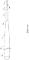
- Figure 1 is a partial cross-sectional side view of an example guidewire 10.
- Guidewire 10 may include a core wire 12.
- a sheath 14 may be disposed along at least a portion of core wire 12.
- a tip member 16 may be disposed about a portion of core wire 12.
- Core wire 12 which can also be seen in Figure 2 , may include a first or distal constant diameter section 18.
- a first tapered section 20 may be coupled to distal constant diameter section 18.
- a proximal end of distal constant diameter section 18 may be attached to a distal end of first tapered section 20.
- a second or intermediate constant diameter section 22 may be coupled to first tapered section 20.
- a proximal end of first tapered section 20 may be attached to a distal end of intermediate constant diameter section 22.
- a second tapered section 24 may be coupled to intermediate constant diameter section 22.
- a proximal end of intermediate constant diameter section 22 may be attached to a distal end of second tapered section 24.
- a third or proximal constant diameter section 26 may be coupled to second tapered section 24.
- a proximal end of second tapered section 24 may be attached to a distal end of proximal constant diameter section 26.
- Core wire 12 may include other sections.
- core wire 12 may be a unitary structure or otherwise formed from a single monolith of material. In other embodiments, core wire 12 may be formed from a plurality of different structures that are secured together. This may include one or more of sections 18/20/22/24/26 being separate structures that are secured to the remaining sections of core wire 12. In such embodiments, the one or more separate structures may be secured to remaining sections of core wire 12 using a suitable bonding technique such as welding, brazing, thermal bonding, adhesive bonding, mechanical bonding and/or the use of a mechanical connector, or the like.
- core wire 12 may vary. Disclosed herein are some example dimensions for the various sections of core wire 12. These dimensions are meant to be examples and are not intended to be limiting. Other dimensions are contemplated.
- proximal constant diameter section 26 may have a length (represented in Figure 1 as dimension D1) of about 200-600cm (78.4-236.2 inches), or about 260-500cm (102.4-196.9 inches).
- the diameter of proximal constant diameter section 26 may be about 0.01-0.04 inches, or about 0.015-0.030 inches, or about 0.023 inches.
- Second tapered section 24 may have a length (represented in Figure 1 as dimension D2) of about 1-50cm (0.4-19.7 inches), or about 2-50cm (0.8-19.7 inches), or about 2-15cm (0.8-5.9 inches), or about 2-10cm (0.8-3.9 inches), or about 5 cm (2 inches).
- the diameter of second tapered section 24 may vary from a diameter that is equal to or approximately equal to the diameter of proximal constant diameter section 26 to a diameter that is equal to or approximately equal to the diameter of intermediate constant diameter section 22.
- the transition in diameter may be a linear taper or non-linear taper.
- the tapering of second tapered section 24 may be a parabolic taper, a curvilinear taper, a straight taper, a function of a non-linear equation (e.g., a second order equation, a third order equation, a fourth order equation, or the like), or the like.
- the taper may be constant along the length of second tapered section 24 or the taper may vary along the length.
- the taper may include one or more steps in diameter.
- Intermediate constant diameter section 22 may have a length (represented in Figure 1 as dimension D3) of about 0.5-20cm (0.2-7.9 inches), or about 1-10cm (0.4-4 inches), or about 2.5-7.5cm (1-3 inches).
- the diameter of intermediate constant diameter section 22 may be about 0.001-0.04 inches, or about 0.005-0.015 inches, or about 0.01 inches.
- First tapered section 20 may have a length (represented in Figure 1 as dimension D4) of about 0.1-10cm (0.04-4 inches), or about 0.5-10cm (0.2-4 inches), or about 0.5-3cm (0.2-1.2 inches), or about 1 cm (0.4 inches).
- the diameter of first tapered section 20 may vary from a diameter that is equal to or approximately equal to the diameter of intermediate constant diameter section 22 to a diameter that is equal to or approximately equal to the diameter of distal constant diameter section 18.
- the transition in diameter may be a linear taper or non-linear taper.
- first tapered section 20 may be a parabolic taper, a curvilinear taper, a straight taper, a function of a non-linear equation (e.g., a second order equation, a third order equation, a fourth order equation, or the like), or the like.
- the taper may be constant along the length of first tapered section 20 or the taper may vary along the length.
- the taper may include one or more steps in diameter.
- Distal constant diameter section 18 may have a length (represented in Figure 1 as dimension D5) of about 0.1-5cm (0.04-2 inches), or about 0.1-2.5cm (0.04-1 inches), or about 1.5cm (0.6 inches).
- the diameter of distal constant diameter section 18 may be about 0.001-0.02 inches, or about 0.001-0.008 inches, or about 0.005 inches.
- the ratio of length of distal constant diameter section 18 to the diameter of distal constant diameter section 18 may be in the range of about 100:1-1500:1, or about 200:1-1200:1, or about 800:1-1200:1.
- distal constant diameter section 18 may have a cross-sectional shape that is substantially round. In other embodiments, distal constant diameter section 18 may be flattened or otherwise have a non-circular cross-sectional shape.
- Forming core wire 12 may include a grinding technique such as through the use of a centerless grinder.
- a centerless grinder may be used to form core wire 12.
- the centerless grinding teachnique may be modified to use a thinner cutting wheel, which may allow for greater precision and/or for the creature of increasing and decreasing tapers along the length of core wire 12.
- different grinding modes may be used to form the desired configuration of core wire 12 such as "OD" mode.
- Guidewires for using in coronary interventions are often designed to have a relatively stiff proximal section for providing "pushability" and a relatively flexible distal region and/or tip.
- coronary guidewires may be designed to avoid kinking or prolapsing when being advanced through a blood vessel.
- a kinked or prolapsed guidewire may not be fully functional and may not be suitable for guiding other diagnostic and/or therapeutic devices to a target region.
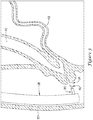
- Guidewire 10 may find utility for use in endoscope interventions such as accessing the common bile duct (and/or the biliary tree), the pancreatic duct (and/or the pancreatic tree), or the like. Unlike coronary guidewires, guidewire 10 is designed to have one or more pre-determined inflection points where guidewire 10 may prolapse or otherwise form a loop. This design may desirably allow guidewire 10 to be used in endoscopic interventions or otherwise be used along the biliary or pancreatic tree.
- the ability of guidewire 10 to form a predictable, pre-determined loop configuration may desirably impact the ability of guidewire 10 to cannulate anatomical structures such as the papilla of Vater, gain access to body lumens such as the common bile duct and/or the pancreatic duct, or otherwise perform endoscopic interventions.
- first inflection point 28 may be defined where distal constant diameter section 18 and first tapered section 20 meet. Because of the length of distal constant diameter section 18, first inflection point 28 may be positioned relatively close to the distal end of guidewire 10. When guidewire 10 is subjected to a suitable longitudinal force, distal constant diameter section 18 may prolapse or otherwise form a loop as shown in Figure 3 . In at least some embodiments, the amount of force may be relatively low. For example, guidewire 10 may form the loop at first inflection point 28 when subjected to about 20-200g of longitudinal force, or about 20-200g of longitudinal force.
- the amount of longitudinal force that may cause guidewire 10 to form a loop at first inflection point 28 may be about 1.1-2.0 times the insertion force (e.g., the force needed to insert guidewire 10 into a catheter, endoscope, or another device), or about 1.2-1.5 times the insertion force, or about 1.25 times the insertion force.
- first inflection point 28 is positioned close to the distal end of guidewire 10, the loop formed when guidewire 10 may be shorter, more tightly associated with the rest of the guidewire (e.g., the radius of curvature may be kept to a minimum), and less force may be applied to the surrounding anatomy.
- guidewire 10 may form a loop more easily, may have a better "feel” for clinicians, and may also be able to revert back to a linear state more easily and/or with less trauma to the surrounding tissue.
- the guidewire 10 may be able to "flick” or otherwise snap back to a more "unlooped” state so that guidewire 10 can continue to advance through the anatomy.
- guidewire 10 may include a plurality of inflection points.
- a second inflection point 30 may be defined where intermediate constant diameter section 22 and second tapered section 24 meet.
- the sections of core wire 12 distal of second inflection point 30 may prolapse or otherwise form a loop as shown in Figure 4 .
- the amount of force may greater than that of first inflection point 28.
- guidewire 10 may form the loop at second inflection point 30 when subjected to about 250-700g of longitudinal force.
- the amount of longitudinal force that may cause guidewire 10 to form a loop at second inflection point 30 may be about 1.75-2.5 times the insertion force (e.g., the force needed to insert guidewire 10 into a catheter, endoscope, or another device), or about 1.8-2.2 times the insertion force, or about 2 times the insertion force.
- guidewire 10 may form a loop at a specific location along the length thereof, with a specific force, and with a controlled (and/or reduced) circumferential force on the body lumen.
- inflection points 28/30 may be defined where a constant diameter section meets a tapered section.
- other structural modifications may also be utilized to define an inflection point such as stiffened regions of core wire 12, structures secured to core wire 12 to impart stiffness, changes in the location and/or composition of the sections of core wire 12, changes in the composition and/or location of sheath 14 and/or tip member 16, or the like.
- guidewire 10 may be advanced through a body lumen such as the duodenum 32 to a position adjacent to the papilla of Vater 34 as shown in Figure 5 . This may include the use of a cannulation or guide catheter 36 and/or an endoscope 38. Guidewire 10 may be advanced out from guide catheter 36 and into engagement with the papilla of Vater 34. If a suitable amount of resistance is encountered, guidewire 10 may prolapse or form a loop a first inflection point 28 as shown in Figure 6 .
- Guidewire 10 may be advanced through the papilla of Vater 34 to a suitable diagnostic and/or treatment site such as along the biliary tract (e.g., the common bile duct 40) or the pancreatic tract (e.g., the pancreatic duct 42).
- a suitable diagnostic and/or treatment site such as along the biliary tract (e.g., the common bile duct 40) or the pancreatic tract (e.g., the pancreatic duct 42).
- guidewire 10 is shown advanced into the common bile duct 40 in Figure 7 .
- the materials that can be used for the various components of guidewire 10 may include metals, metal alloys, polymers, metal-polymer composites, ceramics, combinations thereof, and the like, or other suitable materials.
- suitable polymers may include polytetrafluoroethylene (PTFE), ethylene tetrafluoroethylene (ETFE), fluorinated ethylene propylene (FEP), polyoxymethylene (POM, for example, DELRIN® available from DuPont), polyether block ester, polyurethane (for example, Polyurethane 85A), polypropylene (PP), polyvinylchloride (PVC), polyether-ester (for example, ARNITEL® available from DSM Engineering Plastics), ether or ester based copolymers (for example, butylene/poly(alkylene ether) phthalate and/or other polyester elastomers such as HYTREL® available from DuPont), polyamide (for example, DURETHAN® available from Bayer or CRISTAMID® available from
- suitable metals and metal alloys include stainless steel, such as 304V, 304L, and 316LV stainless steel; mild steel; nickel-titanium alloy such as linear-elastic and/or super-elastic nitinol; other nickel alloys such as nickel-chromium-molybdenum alloys (e.g., UNS: N06625 such as INCONEL® 625, UNS: N06022 such as HASTELLOY® C-22®, UNS: N10276 such as HASTELLOY® C276®, other HASTELLOY® alloys, and the like), nickel-copper alloys (e.g., UNS: N04400 such as MONEL® 400, NICKELVAC® 400, NICORROS® 400, and the like), nickel-cobalt-chromium-molybdenum alloys (e.g., UNS: R30035 such as MP35-N® and the like), nickel-molybdenum alloys (e.g.,
- Linear elastic and/or non-super-elastic nitinol may be distinguished from super elastic nitinol in that the linear elastic and/or non-super-elastic nitinol does not display a substantial "superelastic plateau” or “flag region” in its stress/strain curve like super elastic nitinol does.
- linear elastic and/or non-super-elastic nitinol as recoverable strain increases, the stress continues to increase in a substantially linear, or a somewhat, but not necessarily entirely linear relationship until plastic deformation begins or at least in a relationship that is more linear that the super elastic plateau and/or flag region that may be seen with super elastic nitinol.
- linear elastic and/or non-super-elastic nitinol may also be termed "substantially" linear elastic and/or non-super-elastic nitinol.
- linear elastic and/or non-super-elastic nitinol may also be distinguishable from super elastic nitinol in that linear elastic and/or non-super-elastic nitinol may accept up to about 2-5% strain while remaining substantially elastic (e.g., before plastically deforming) whereas super elastic nitinol may accept up to about 8% strain before plastically deforming. Both of these materials can be distinguished from other linear elastic materials such as stainless steel (that can also can be distinguished based on its composition), which may accept only about 0.2 to 0.44 percent strain before plastically deforming.
- the linear elastic and/or non-super-elastic nickel-titanium alloy is an alloy that does not show any martensite/austenite phase changes that are detectable by differential scanning calorimetry (DSC) and dynamic metal thermal analysis (DMTA) analysis over a large temperature range.
- DSC differential scanning calorimetry
- DMTA dynamic metal thermal analysis
- the mechanical bending properties of such material may therefore be generally inert to the effect of temperature over this very broad range of temperature.
- the mechanical bending properties of the linear elastic and/or non-super-elastic nickel-titanium alloy at ambient or room temperature are substantially the same as the mechanical properties at body temperature, for example, in that they do not display a super-elastic plateau and/or flag region.
- the linear elastic and/or non-super-elastic nickel-titanium alloy maintains its linear elastic and/or non-super-elastic characteristics and/or properties.
- the linear elastic and/or non-super-elastic nickel-titanium alloy may be in the range of about 50 to about 60 weight percent nickel, with the remainder being essentially titanium. In some embodiments, the composition is in the range of about 54 to about 57 weight percent nickel.
- a suitable nickel-titanium alloy is FHP-NT alloy commercially available from Furukawa Techno Material Co. of Kanagawa, Japan. Some examples of nickel titanium alloys are disclosed in U.S. Patent Nos. 5,238,004 and 6,508,803 . Other suitable materials may include ULTANIUMTM (available from Neo-Metrics) and GUM METALTM (available from Toyota).
- a superelastic alloy for example a superelastic nitinol can be used to achieve desired properties.
- portions or all of core wire 12 may also be doped with, made of, or otherwise include a radiopaque material.
- Radiopaque materials are understood to be materials capable of producing a relatively bright image on a fluoroscopy screen or another imaging technique during a medical procedure. This relatively bright image aids the user of guidewire 10 in determining its location.
- Some examples of radiopaque materials can include, but are not limited to, gold, platinum, palladium, tantalum, tungsten alloy, polymer material loaded with a radiopaque filler, and the like. Additionally, other radiopaque marker bands and/or coils may also be incorporated into the design of guidewire 10 to achieve the same result.
- a degree of Magnetic Resonance Imaging (MRI) compatibility is imparted into guidewire 10.
- core wire 12, or portions thereof may be made of a material that does not substantially distort the image and create substantial artifacts (i.e., gaps in the image). Certain ferromagnetic materials, for example, may not be suitable because they may create artifacts in an MRI image. Core wire 12, or portions thereof, may also be made from a material that the MRI machine can image.
- Some materials that exhibit these characteristics include, for example, tungsten, cobalt-chromium-molybdenum alloys (e.g., UNS: R30003 such as ELGILOY®, PHYNOX®, and the like), nickel-cobalt-chromium-molybdenum alloys (e.g., UNS: R30035 such as MP35-N® and the like), nitinol, and the like, and others.
- cobalt-chromium-molybdenum alloys e.g., UNS: R30003 such as ELGILOY®, PHYNOX®, and the like
- nickel-cobalt-chromium-molybdenum alloys e.g., UNS: R30035 such as MP35-N® and the like
- nitinol and the like, and others.
- the entire core wire 12 can be made of the same material along its length, or in some embodiments, can include portions or sections made of different materials.
- the material used to construct core wire 12 is chosen to impart varying flexibility and stiffness characteristics to different portions of core wire 12.
- the different portions can be connected using a suitable connecting technique and/or with a connector.
- the different portions of core wire 12 can be connected using welding (including laser welding), soldering, brazing, adhesive, or the like, or combinations thereof. These techniques can be utilized regardless of whether or not a connector is utilized.
Landscapes
- Health & Medical Sciences (AREA)
- Life Sciences & Earth Sciences (AREA)
- Biophysics (AREA)
- Pulmonology (AREA)
- Engineering & Computer Science (AREA)
- Anesthesiology (AREA)
- Biomedical Technology (AREA)
- Heart & Thoracic Surgery (AREA)
- Hematology (AREA)
- Animal Behavior & Ethology (AREA)
- General Health & Medical Sciences (AREA)
- Public Health (AREA)
- Veterinary Medicine (AREA)
- Media Introduction/Drainage Providing Device (AREA)
- Prostheses (AREA)
- Surgical Instruments (AREA)
Claims (15)
- Fil de guidage médical (10), comprenant :un fil d'âme (12) ayant un axe longitudinal, le fil d'âme (12) incluant :une section de diamètre constant distale (18) ayant une extrémité distale et une extrémité proximale, l'extrémité distale de la section de diamètre constant distale (18) définissant une extrémité distale du fil d'âme (12) ;une première section conique (20) ayant une extrémité distale et une extrémité proximale, l'extrémité distale de la première section conique (20) étant fixée à l'extrémité proximale de la section de diamètre constant distale (18) de telle sorte qu'un premier point d'inflexion (28) est défini où l'extrémité distale de la première section conique (20) et l'extrémité proximale de la section de diamètre constant distale (18) se rencontrent ;une section de diamètre constant intermédiaire (22) ayant une extrémité proximale et une extrémité distale, l'extrémité distale de la section de diamètre constant intermédiaire (22) étant fixée à l'extrémité proximale de la première section conique (20) ;une seconde section conique (24) ayant une extrémité proximale et une extrémité distale, l'extrémité distale de la seconde section conique (24) étant fixée à l'extrémité proximale de la section de diamètre constant intermédiaire (22) de telle sorte qu'un second point d'inflexion (30) est défini où l'extrémité distale de la seconde section conique (24) et l'extrémité proximale de la section de diamètre constant intermédiaire (22) se rencontrent ; etune section de diamètre constant proximale (26) ayant une extrémité proximale et une extrémité distale, l'extrémité distale de la section de diamètre constant proximale (26) étant fixée à l'extrémité proximale de la seconde section conique (24) ;où le fil d'âme (12) est configuré de telle sorte que quand une première force longitudinale prédéterminée est appliquée à l'extrémité distale de la section de diamètre constant distale (18) le long de l'axe longitudinal, la section de diamètre constant distale (18) avance de telle sorte qu'une première boucle est définie au niveau du premier point d'inflexion (28).
- Fil de guidage selon la revendication 1, où le fil d'âme (12) est configuré de telle sorte que quand la première boucle est définie au niveau du premier point d'inflexion (28), la première boucle définit une extrémité distale du fil d'âme (12), et quand une seconde force longitudinale prédéterminée est appliquée à l'extrémité distale le long de l'axe longitudinal, la section de diamètre constant intermédiaire (22) avance pour définir une seconde boucle au niveau du second point d'inflexion (30).
- Fil de guidage selon la revendication 2, où la première force longitudinale prédéterminée est inférieure à la seconde force longitudinale prédéterminée.
- Fil de guidage selon l'une quelconque des revendications 2-3, où la première force longitudinale prédéterminée est dans la plage de 20 g à 200 g.
- Fil de guidage selon l'une quelconque des revendications 2-4, où la seconde force longitudinale prédéterminée est dans la plage de 250 g à 700 g.
- Fil de guidage selon l'une quelconque des revendications 1-5, où la section de diamètre constant distale (18) a une longueur dans la plage de 0,1 cm à 2,5 cm.
- Fil de guidage selon l'une quelconque des revendications 1-6, où la section de diamètre constant distale (18) a un diamètre dans la plage de 0,025 mm à 0,203 mm (0,001 pouce à 0,008 pouce).
- Fil de guidage selon l'une quelconque des revendications 1-7, où la première section conique (20) a une longueur dans la plage de 0,5 cm à 3 cm, où la section de diamètre constant intermédiaire (22) a une longueur dans la plage de 1 cm à 10 cm et où la seconde section conique (24) a une longueur dans la plage de 2 cm à 50 cm.
- Fil de guidage selon l'une quelconque des revendications 1-8, où la section de diamètre constant intermédiaire (22) a un diamètre dans la plage de 0,127 mm à 0,381 mm (0,005 pouce à 0,015 pouce).
- Fil de guidage selon l'une quelconque des revendications 1-9, où la section de diamètre constant proximale (26) a un diamètre dans la plage de 0,381 mm à 0,762 mm (0,015 pouce à 0,030 pouce).
- Fil de guidage selon l'une quelconque des revendications 1-10, où le rapport de la longueur de la section de diamètre constant distale (18) au diamètre de la section de diamètre constant distale (18) est dans la plage de 800 : 1 à 1200 : 1.
- Fil de guidage selon l'une quelconque des revendications 1-11, où le fil d'âme (12) comprend un matériau superélastique.
- Fil de guidage selon la revendication 12, où le fil d'âme (12) comprend un alliage nickel-titane superélastique.
- Fil de guidage selon l'une quelconque des revendications 1-13, comprenant en outre une gaine externe (14) disposée le long d'au moins une partie du fil d'âme (12).
- Fil de guidage selon l'une quelconque des revendications 1-14, comprenant en outre un élément de bout (16) disposé le long d'au moins la section de diamètre constant distale (18).
Applications Claiming Priority (2)
| Application Number | Priority Date | Filing Date | Title |
|---|---|---|---|
| US201361908843P | 2013-11-26 | 2013-11-26 | |
| PCT/US2014/066665 WO2015080948A1 (fr) | 2013-11-26 | 2014-11-20 | Dispositifs medicaux permettant d'acceder a des lumieres corporelles |
Publications (2)
| Publication Number | Publication Date |
|---|---|
| EP3074079A1 EP3074079A1 (fr) | 2016-10-05 |
| EP3074079B1 true EP3074079B1 (fr) | 2020-01-15 |
Family
ID=52011335
Family Applications (1)
| Application Number | Title | Priority Date | Filing Date |
|---|---|---|---|
| EP14808795.0A Active EP3074079B1 (fr) | 2013-11-26 | 2014-11-20 | Dispositifs medicaux permettant d'acceder a des lumieres corporelles |
Country Status (5)
| Country | Link |
|---|---|
| US (1) | US20150148706A1 (fr) |
| EP (1) | EP3074079B1 (fr) |
| JP (1) | JP2017500925A (fr) |
| CN (1) | CN106413794A (fr) |
| WO (1) | WO2015080948A1 (fr) |
Families Citing this family (8)
| Publication number | Priority date | Publication date | Assignee | Title |
|---|---|---|---|---|
| US10391282B2 (en) * | 2014-07-08 | 2019-08-27 | Teleflex Innovations S.À.R.L. | Guidewires and methods for percutaneous occlusion crossing |
| JP5874885B1 (ja) * | 2015-02-24 | 2016-03-02 | 株式会社エフエムディ | 医療用ガイドワイヤ |
| US11219744B2 (en) * | 2017-04-21 | 2022-01-11 | Medtronic Vascular, Inc. | Push wire for endoluminal medical device |
| KR102445728B1 (ko) * | 2017-10-12 | 2022-09-22 | 아사히 인텍크 가부시키가이샤 | 가이드 와이어 |
| WO2019073571A1 (fr) | 2017-10-12 | 2019-04-18 | 朝日インテック株式会社 | Fil-guide |
| WO2019083757A1 (fr) | 2017-10-26 | 2019-05-02 | Teleflex Innovations S.A.R.L. | Ensemble et dispositif de cathéter sous-intimal |
| WO2019109063A2 (fr) | 2017-12-03 | 2019-06-06 | Paul Ram H Jr | Guide-fil d'intervention compatible avec l'irm |
| US20210128874A1 (en) * | 2019-10-31 | 2021-05-06 | Abbott Cardiovascular Systems Inc. | Guidewire having parabolic grind profile |
Family Cites Families (13)
| Publication number | Priority date | Publication date | Assignee | Title |
|---|---|---|---|---|
| JPS6063066A (ja) * | 1983-09-16 | 1985-04-11 | テルモ株式会社 | カテ−テル用ガイドワイヤ |
| US5238004A (en) | 1990-04-10 | 1993-08-24 | Boston Scientific Corporation | High elongation linear elastic guidewire |
| US5916178A (en) * | 1995-03-30 | 1999-06-29 | Medtronic, Inc. | Steerable high support guidewire with thin wall nitinol tube |
| US6508803B1 (en) | 1998-11-06 | 2003-01-21 | Furukawa Techno Material Co., Ltd. | Niti-type medical guide wire and method of producing the same |
| US7717864B1 (en) * | 1998-12-31 | 2010-05-18 | Advanced Cardiovascular Systems, Inc. | Composite guidewire with drawn and filled tube construction |
| US7468045B2 (en) * | 2001-01-12 | 2008-12-23 | Minnesota Medical Development, Inc. | Titanium molybdenum alloy guidewire |
| US7785273B2 (en) * | 2003-09-22 | 2010-08-31 | Boston Scientific Scimed, Inc. | Guidewire with reinforcing member |
| JP3694312B1 (ja) * | 2005-01-26 | 2005-09-14 | 朝日インテック株式会社 | 医療用ガイドワイヤ |
| US20060173382A1 (en) * | 2005-01-31 | 2006-08-03 | John Schreiner | Guidewire with superelastic core |
| CA2636266A1 (fr) * | 2006-01-12 | 2007-07-19 | Minnesota Medical Development, Inc. | Fils de guidage d'alliage de molybdene titane |
| JP5411533B2 (ja) * | 2009-03-09 | 2014-02-12 | テルモ株式会社 | ガイドワイヤ |
| JP5013547B2 (ja) * | 2009-06-16 | 2012-08-29 | 朝日インテック株式会社 | 医療用ガイドワイヤ |
| US20130110000A1 (en) * | 2011-10-31 | 2013-05-02 | Terumo Medical Corporation | Dual Diameter Introducer Guide Wire |
-
2014
- 2014-11-20 US US14/549,191 patent/US20150148706A1/en not_active Abandoned
- 2014-11-20 JP JP2016534202A patent/JP2017500925A/ja active Pending
- 2014-11-20 WO PCT/US2014/066665 patent/WO2015080948A1/fr active Application Filing
- 2014-11-20 EP EP14808795.0A patent/EP3074079B1/fr active Active
- 2014-11-20 CN CN201480074033.9A patent/CN106413794A/zh active Pending
Non-Patent Citations (1)
| Title |
|---|
| None * |
Also Published As
| Publication number | Publication date |
|---|---|
| EP3074079A1 (fr) | 2016-10-05 |
| JP2017500925A (ja) | 2017-01-12 |
| CN106413794A (zh) | 2017-02-15 |
| US20150148706A1 (en) | 2015-05-28 |
| WO2015080948A1 (fr) | 2015-06-04 |
Similar Documents
| Publication | Publication Date | Title |
|---|---|---|
| US11571545B2 (en) | Guide extension catheter | |
| US9764118B2 (en) | Guide extension catheter | |
| US20200023159A1 (en) | Integrated catheter system | |
| EP3074079B1 (fr) | Dispositifs medicaux permettant d'acceder a des lumieres corporelles | |
| US9993613B2 (en) | Guide extension catheter | |
| EP2874690B1 (fr) | Cathéter d'extension de guidage | |
| US7841994B2 (en) | Medical device for crossing an occlusion in a vessel | |
| US10058443B2 (en) | Stent delivery systems and methods for use | |
| US11826517B2 (en) | Guide extension catheter | |
| US20140018773A1 (en) | Guide extension catheter | |
| US20150352330A1 (en) | Deliver assist device for guide catheter |
Legal Events
| Date | Code | Title | Description |
|---|---|---|---|
| PUAI | Public reference made under article 153(3) epc to a published international application that has entered the european phase |
Free format text: ORIGINAL CODE: 0009012 |
|
| 17P | Request for examination filed |
Effective date: 20160627 |
|
| AK | Designated contracting states |
Kind code of ref document: A1 Designated state(s): AL AT BE BG CH CY CZ DE DK EE ES FI FR GB GR HR HU IE IS IT LI LT LU LV MC MK MT NL NO PL PT RO RS SE SI SK SM TR |
|
| AX | Request for extension of the european patent |
Extension state: BA ME |
|
| DAX | Request for extension of the european patent (deleted) | ||
| GRAP | Despatch of communication of intention to grant a patent |
Free format text: ORIGINAL CODE: EPIDOSNIGR1 |
|
| STAA | Information on the status of an ep patent application or granted ep patent |
Free format text: STATUS: GRANT OF PATENT IS INTENDED |
|
| INTG | Intention to grant announced |
Effective date: 20190802 |
|
| GRAS | Grant fee paid |
Free format text: ORIGINAL CODE: EPIDOSNIGR3 |
|
| GRAA | (expected) grant |
Free format text: ORIGINAL CODE: 0009210 |
|
| STAA | Information on the status of an ep patent application or granted ep patent |
Free format text: STATUS: THE PATENT HAS BEEN GRANTED |
|
| AK | Designated contracting states |
Kind code of ref document: B1 Designated state(s): AL AT BE BG CH CY CZ DE DK EE ES FI FR GB GR HR HU IE IS IT LI LT LU LV MC MK MT NL NO PL PT RO RS SE SI SK SM TR |
|
| REG | Reference to a national code |
Ref country code: CH Ref legal event code: EP Ref country code: GB Ref legal event code: FG4D |
|
| REG | Reference to a national code |
Ref country code: IE Ref legal event code: FG4D |
|
| REG | Reference to a national code |
Ref country code: DE Ref legal event code: R096 Ref document number: 602014060117 Country of ref document: DE |
|
| REG | Reference to a national code |
Ref country code: AT Ref legal event code: REF Ref document number: 1224629 Country of ref document: AT Kind code of ref document: T Effective date: 20200215 |
|
| REG | Reference to a national code |
Ref country code: NL Ref legal event code: FP |
|
| REG | Reference to a national code |
Ref country code: LT Ref legal event code: MG4D |
|
| PG25 | Lapsed in a contracting state [announced via postgrant information from national office to epo] |
Ref country code: PT Free format text: LAPSE BECAUSE OF FAILURE TO SUBMIT A TRANSLATION OF THE DESCRIPTION OR TO PAY THE FEE WITHIN THE PRESCRIBED TIME-LIMIT Effective date: 20200607 Ref country code: NO Free format text: LAPSE BECAUSE OF FAILURE TO SUBMIT A TRANSLATION OF THE DESCRIPTION OR TO PAY THE FEE WITHIN THE PRESCRIBED TIME-LIMIT Effective date: 20200415 Ref country code: FI Free format text: LAPSE BECAUSE OF FAILURE TO SUBMIT A TRANSLATION OF THE DESCRIPTION OR TO PAY THE FEE WITHIN THE PRESCRIBED TIME-LIMIT Effective date: 20200115 Ref country code: RS Free format text: LAPSE BECAUSE OF FAILURE TO SUBMIT A TRANSLATION OF THE DESCRIPTION OR TO PAY THE FEE WITHIN THE PRESCRIBED TIME-LIMIT Effective date: 20200115 |
|
| PG25 | Lapsed in a contracting state [announced via postgrant information from national office to epo] |
Ref country code: GR Free format text: LAPSE BECAUSE OF FAILURE TO SUBMIT A TRANSLATION OF THE DESCRIPTION OR TO PAY THE FEE WITHIN THE PRESCRIBED TIME-LIMIT Effective date: 20200416 Ref country code: HR Free format text: LAPSE BECAUSE OF FAILURE TO SUBMIT A TRANSLATION OF THE DESCRIPTION OR TO PAY THE FEE WITHIN THE PRESCRIBED TIME-LIMIT Effective date: 20200115 Ref country code: SE Free format text: LAPSE BECAUSE OF FAILURE TO SUBMIT A TRANSLATION OF THE DESCRIPTION OR TO PAY THE FEE WITHIN THE PRESCRIBED TIME-LIMIT Effective date: 20200115 Ref country code: LV Free format text: LAPSE BECAUSE OF FAILURE TO SUBMIT A TRANSLATION OF THE DESCRIPTION OR TO PAY THE FEE WITHIN THE PRESCRIBED TIME-LIMIT Effective date: 20200115 Ref country code: IS Free format text: LAPSE BECAUSE OF FAILURE TO SUBMIT A TRANSLATION OF THE DESCRIPTION OR TO PAY THE FEE WITHIN THE PRESCRIBED TIME-LIMIT Effective date: 20200515 Ref country code: BG Free format text: LAPSE BECAUSE OF FAILURE TO SUBMIT A TRANSLATION OF THE DESCRIPTION OR TO PAY THE FEE WITHIN THE PRESCRIBED TIME-LIMIT Effective date: 20200415 |
|
| REG | Reference to a national code |
Ref country code: DE Ref legal event code: R097 Ref document number: 602014060117 Country of ref document: DE |
|
| PG25 | Lapsed in a contracting state [announced via postgrant information from national office to epo] |
Ref country code: CZ Free format text: LAPSE BECAUSE OF FAILURE TO SUBMIT A TRANSLATION OF THE DESCRIPTION OR TO PAY THE FEE WITHIN THE PRESCRIBED TIME-LIMIT Effective date: 20200115 Ref country code: ES Free format text: LAPSE BECAUSE OF FAILURE TO SUBMIT A TRANSLATION OF THE DESCRIPTION OR TO PAY THE FEE WITHIN THE PRESCRIBED TIME-LIMIT Effective date: 20200115 Ref country code: SK Free format text: LAPSE BECAUSE OF FAILURE TO SUBMIT A TRANSLATION OF THE DESCRIPTION OR TO PAY THE FEE WITHIN THE PRESCRIBED TIME-LIMIT Effective date: 20200115 Ref country code: LT Free format text: LAPSE BECAUSE OF FAILURE TO SUBMIT A TRANSLATION OF THE DESCRIPTION OR TO PAY THE FEE WITHIN THE PRESCRIBED TIME-LIMIT Effective date: 20200115 Ref country code: EE Free format text: LAPSE BECAUSE OF FAILURE TO SUBMIT A TRANSLATION OF THE DESCRIPTION OR TO PAY THE FEE WITHIN THE PRESCRIBED TIME-LIMIT Effective date: 20200115 Ref country code: SM Free format text: LAPSE BECAUSE OF FAILURE TO SUBMIT A TRANSLATION OF THE DESCRIPTION OR TO PAY THE FEE WITHIN THE PRESCRIBED TIME-LIMIT Effective date: 20200115 Ref country code: DK Free format text: LAPSE BECAUSE OF FAILURE TO SUBMIT A TRANSLATION OF THE DESCRIPTION OR TO PAY THE FEE WITHIN THE PRESCRIBED TIME-LIMIT Effective date: 20200115 Ref country code: RO Free format text: LAPSE BECAUSE OF FAILURE TO SUBMIT A TRANSLATION OF THE DESCRIPTION OR TO PAY THE FEE WITHIN THE PRESCRIBED TIME-LIMIT Effective date: 20200115 |
|
| REG | Reference to a national code |
Ref country code: AT Ref legal event code: MK05 Ref document number: 1224629 Country of ref document: AT Kind code of ref document: T Effective date: 20200115 |
|
| PLBE | No opposition filed within time limit |
Free format text: ORIGINAL CODE: 0009261 |
|
| STAA | Information on the status of an ep patent application or granted ep patent |
Free format text: STATUS: NO OPPOSITION FILED WITHIN TIME LIMIT |
|
| 26N | No opposition filed |
Effective date: 20201016 |
|
| PG25 | Lapsed in a contracting state [announced via postgrant information from national office to epo] |
Ref country code: AT Free format text: LAPSE BECAUSE OF FAILURE TO SUBMIT A TRANSLATION OF THE DESCRIPTION OR TO PAY THE FEE WITHIN THE PRESCRIBED TIME-LIMIT Effective date: 20200115 Ref country code: IT Free format text: LAPSE BECAUSE OF FAILURE TO SUBMIT A TRANSLATION OF THE DESCRIPTION OR TO PAY THE FEE WITHIN THE PRESCRIBED TIME-LIMIT Effective date: 20200115 |
|
| PG25 | Lapsed in a contracting state [announced via postgrant information from national office to epo] |
Ref country code: PL Free format text: LAPSE BECAUSE OF FAILURE TO SUBMIT A TRANSLATION OF THE DESCRIPTION OR TO PAY THE FEE WITHIN THE PRESCRIBED TIME-LIMIT Effective date: 20200115 Ref country code: SI Free format text: LAPSE BECAUSE OF FAILURE TO SUBMIT A TRANSLATION OF THE DESCRIPTION OR TO PAY THE FEE WITHIN THE PRESCRIBED TIME-LIMIT Effective date: 20200115 |
|
| PG25 | Lapsed in a contracting state [announced via postgrant information from national office to epo] |
Ref country code: MC Free format text: LAPSE BECAUSE OF FAILURE TO SUBMIT A TRANSLATION OF THE DESCRIPTION OR TO PAY THE FEE WITHIN THE PRESCRIBED TIME-LIMIT Effective date: 20200115 |
|
| REG | Reference to a national code |
Ref country code: CH Ref legal event code: PL |
|
| PG25 | Lapsed in a contracting state [announced via postgrant information from national office to epo] |
Ref country code: LU Free format text: LAPSE BECAUSE OF NON-PAYMENT OF DUE FEES Effective date: 20201120 |
|
| REG | Reference to a national code |
Ref country code: BE Ref legal event code: MM Effective date: 20201130 |
|
| PG25 | Lapsed in a contracting state [announced via postgrant information from national office to epo] |
Ref country code: LI Free format text: LAPSE BECAUSE OF NON-PAYMENT OF DUE FEES Effective date: 20201130 Ref country code: CH Free format text: LAPSE BECAUSE OF NON-PAYMENT OF DUE FEES Effective date: 20201130 |
|
| PG25 | Lapsed in a contracting state [announced via postgrant information from national office to epo] |
Ref country code: FR Free format text: LAPSE BECAUSE OF NON-PAYMENT OF DUE FEES Effective date: 20201130 |
|
| PG25 | Lapsed in a contracting state [announced via postgrant information from national office to epo] |
Ref country code: TR Free format text: LAPSE BECAUSE OF FAILURE TO SUBMIT A TRANSLATION OF THE DESCRIPTION OR TO PAY THE FEE WITHIN THE PRESCRIBED TIME-LIMIT Effective date: 20200115 Ref country code: MT Free format text: LAPSE BECAUSE OF FAILURE TO SUBMIT A TRANSLATION OF THE DESCRIPTION OR TO PAY THE FEE WITHIN THE PRESCRIBED TIME-LIMIT Effective date: 20200115 Ref country code: CY Free format text: LAPSE BECAUSE OF FAILURE TO SUBMIT A TRANSLATION OF THE DESCRIPTION OR TO PAY THE FEE WITHIN THE PRESCRIBED TIME-LIMIT Effective date: 20200115 |
|
| PG25 | Lapsed in a contracting state [announced via postgrant information from national office to epo] |
Ref country code: MK Free format text: LAPSE BECAUSE OF FAILURE TO SUBMIT A TRANSLATION OF THE DESCRIPTION OR TO PAY THE FEE WITHIN THE PRESCRIBED TIME-LIMIT Effective date: 20200115 Ref country code: AL Free format text: LAPSE BECAUSE OF FAILURE TO SUBMIT A TRANSLATION OF THE DESCRIPTION OR TO PAY THE FEE WITHIN THE PRESCRIBED TIME-LIMIT Effective date: 20200115 |
|
| PG25 | Lapsed in a contracting state [announced via postgrant information from national office to epo] |
Ref country code: BE Free format text: LAPSE BECAUSE OF NON-PAYMENT OF DUE FEES Effective date: 20201130 |
|
| PGFP | Annual fee paid to national office [announced via postgrant information from national office to epo] |
Ref country code: NL Payment date: 20231020 Year of fee payment: 10 |
|
| PGFP | Annual fee paid to national office [announced via postgrant information from national office to epo] |
Ref country code: GB Payment date: 20231019 Year of fee payment: 10 |
|
| PGFP | Annual fee paid to national office [announced via postgrant information from national office to epo] |
Ref country code: IE Payment date: 20231023 Year of fee payment: 10 Ref country code: DE Payment date: 20231019 Year of fee payment: 10 |