EP3073928B1 - Positioning of partial volumes of an anatomy - Google Patents
Positioning of partial volumes of an anatomy Download PDFInfo
- Publication number
- EP3073928B1 EP3073928B1 EP14865068.2A EP14865068A EP3073928B1 EP 3073928 B1 EP3073928 B1 EP 3073928B1 EP 14865068 A EP14865068 A EP 14865068A EP 3073928 B1 EP3073928 B1 EP 3073928B1
- Authority
- EP
- European Patent Office
- Prior art keywords
- imaging
- anatomy
- image
- positioning
- display
- Prior art date
- Legal status (The legal status is an assumption and is not a legal conclusion. Google has not performed a legal analysis and makes no representation as to the accuracy of the status listed.)
- Active
Links
- 210000003484 anatomy Anatomy 0.000 title claims description 34
- 238000003384 imaging method Methods 0.000 claims description 90
- 238000000034 method Methods 0.000 claims description 8
- 238000010276 construction Methods 0.000 claims description 5
- 230000005855 radiation Effects 0.000 claims description 5
- 238000013170 computed tomography imaging Methods 0.000 claims 1
- 238000002059 diagnostic imaging Methods 0.000 claims 1
- 238000002591 computed tomography Methods 0.000 description 6
- 238000003325 tomography Methods 0.000 description 2
- 235000010627 Phaseolus vulgaris Nutrition 0.000 description 1
- 244000046052 Phaseolus vulgaris Species 0.000 description 1
- 238000007408 cone-beam computed tomography Methods 0.000 description 1
- NJPPVKZQTLUDBO-UHFFFAOYSA-N novaluron Chemical group C1=C(Cl)C(OC(F)(F)C(OC(F)(F)F)F)=CC=C1NC(=O)NC(=O)C1=C(F)C=CC=C1F NJPPVKZQTLUDBO-UHFFFAOYSA-N 0.000 description 1
Images


Classifications
-
- A—HUMAN NECESSITIES
- A61—MEDICAL OR VETERINARY SCIENCE; HYGIENE
- A61B—DIAGNOSIS; SURGERY; IDENTIFICATION
- A61B6/00—Apparatus for radiation diagnosis, e.g. combined with radiation therapy equipment
- A61B6/02—Devices for diagnosis sequentially in different planes; Stereoscopic radiation diagnosis
- A61B6/03—Computerised tomographs
- A61B6/032—Transmission computed tomography [CT]
-
- G—PHYSICS
- G01—MEASURING; TESTING
- G01N—INVESTIGATING OR ANALYSING MATERIALS BY DETERMINING THEIR CHEMICAL OR PHYSICAL PROPERTIES
- G01N23/00—Investigating or analysing materials by the use of wave or particle radiation, e.g. X-rays or neutrons, not covered by groups G01N3/00 – G01N17/00, G01N21/00 or G01N22/00
- G01N23/02—Investigating or analysing materials by the use of wave or particle radiation, e.g. X-rays or neutrons, not covered by groups G01N3/00 – G01N17/00, G01N21/00 or G01N22/00 by transmitting the radiation through the material
- G01N23/04—Investigating or analysing materials by the use of wave or particle radiation, e.g. X-rays or neutrons, not covered by groups G01N3/00 – G01N17/00, G01N21/00 or G01N22/00 by transmitting the radiation through the material and forming images of the material
-
- A—HUMAN NECESSITIES
- A61—MEDICAL OR VETERINARY SCIENCE; HYGIENE
- A61B—DIAGNOSIS; SURGERY; IDENTIFICATION
- A61B6/00—Apparatus for radiation diagnosis, e.g. combined with radiation therapy equipment
- A61B6/04—Positioning of patients; Tiltable beds or the like
-
- A—HUMAN NECESSITIES
- A61—MEDICAL OR VETERINARY SCIENCE; HYGIENE
- A61B—DIAGNOSIS; SURGERY; IDENTIFICATION
- A61B6/00—Apparatus for radiation diagnosis, e.g. combined with radiation therapy equipment
- A61B6/02—Devices for diagnosis sequentially in different planes; Stereoscopic radiation diagnosis
- A61B6/03—Computerised tomographs
-
- A—HUMAN NECESSITIES
- A61—MEDICAL OR VETERINARY SCIENCE; HYGIENE
- A61B—DIAGNOSIS; SURGERY; IDENTIFICATION
- A61B6/00—Apparatus for radiation diagnosis, e.g. combined with radiation therapy equipment
- A61B6/04—Positioning of patients; Tiltable beds or the like
- A61B6/0492—Positioning of patients; Tiltable beds or the like using markers or indicia for aiding patient positioning
-
- A—HUMAN NECESSITIES
- A61—MEDICAL OR VETERINARY SCIENCE; HYGIENE
- A61B—DIAGNOSIS; SURGERY; IDENTIFICATION
- A61B6/00—Apparatus for radiation diagnosis, e.g. combined with radiation therapy equipment
- A61B6/08—Auxiliary means for directing the radiation beam to a particular spot, e.g. using light beams
-
- A—HUMAN NECESSITIES
- A61—MEDICAL OR VETERINARY SCIENCE; HYGIENE
- A61B—DIAGNOSIS; SURGERY; IDENTIFICATION
- A61B6/00—Apparatus for radiation diagnosis, e.g. combined with radiation therapy equipment
- A61B6/40—Apparatus for radiation diagnosis, e.g. combined with radiation therapy equipment with arrangements for generating radiation specially adapted for radiation diagnosis
- A61B6/4064—Apparatus for radiation diagnosis, e.g. combined with radiation therapy equipment with arrangements for generating radiation specially adapted for radiation diagnosis specially adapted for producing a particular type of beam
- A61B6/4085—Cone-beams
-
- A—HUMAN NECESSITIES
- A61—MEDICAL OR VETERINARY SCIENCE; HYGIENE
- A61B—DIAGNOSIS; SURGERY; IDENTIFICATION
- A61B6/00—Apparatus for radiation diagnosis, e.g. combined with radiation therapy equipment
- A61B6/42—Apparatus for radiation diagnosis, e.g. combined with radiation therapy equipment with arrangements for detecting radiation specially adapted for radiation diagnosis
- A61B6/4275—Apparatus for radiation diagnosis, e.g. combined with radiation therapy equipment with arrangements for detecting radiation specially adapted for radiation diagnosis using a detector unit almost surrounding the patient, e.g. more than 180°
-
- A—HUMAN NECESSITIES
- A61—MEDICAL OR VETERINARY SCIENCE; HYGIENE
- A61B—DIAGNOSIS; SURGERY; IDENTIFICATION
- A61B6/00—Apparatus for radiation diagnosis, e.g. combined with radiation therapy equipment
- A61B6/44—Constructional features of apparatus for radiation diagnosis
- A61B6/4417—Constructional features of apparatus for radiation diagnosis related to combined acquisition of different diagnostic modalities
-
- A—HUMAN NECESSITIES
- A61—MEDICAL OR VETERINARY SCIENCE; HYGIENE
- A61B—DIAGNOSIS; SURGERY; IDENTIFICATION
- A61B6/00—Apparatus for radiation diagnosis, e.g. combined with radiation therapy equipment
- A61B6/44—Constructional features of apparatus for radiation diagnosis
- A61B6/4429—Constructional features of apparatus for radiation diagnosis related to the mounting of source units and detector units
- A61B6/4435—Constructional features of apparatus for radiation diagnosis related to the mounting of source units and detector units the source unit and the detector unit being coupled by a rigid structure
- A61B6/4441—Constructional features of apparatus for radiation diagnosis related to the mounting of source units and detector units the source unit and the detector unit being coupled by a rigid structure the rigid structure being a C-arm or U-arm
-
- A—HUMAN NECESSITIES
- A61—MEDICAL OR VETERINARY SCIENCE; HYGIENE
- A61B—DIAGNOSIS; SURGERY; IDENTIFICATION
- A61B6/00—Apparatus for radiation diagnosis, e.g. combined with radiation therapy equipment
- A61B6/46—Apparatus for radiation diagnosis, e.g. combined with radiation therapy equipment with special arrangements for interfacing with the operator or the patient
- A61B6/461—Displaying means of special interest
- A61B6/463—Displaying means of special interest characterised by displaying multiple images or images and diagnostic data on one display
-
- A—HUMAN NECESSITIES
- A61—MEDICAL OR VETERINARY SCIENCE; HYGIENE
- A61B—DIAGNOSIS; SURGERY; IDENTIFICATION
- A61B6/00—Apparatus for radiation diagnosis, e.g. combined with radiation therapy equipment
- A61B6/48—Diagnostic techniques
- A61B6/488—Diagnostic techniques involving pre-scan acquisition
-
- A—HUMAN NECESSITIES
- A61—MEDICAL OR VETERINARY SCIENCE; HYGIENE
- A61B—DIAGNOSIS; SURGERY; IDENTIFICATION
- A61B6/00—Apparatus for radiation diagnosis, e.g. combined with radiation therapy equipment
- A61B6/50—Clinical applications
-
- A—HUMAN NECESSITIES
- A61—MEDICAL OR VETERINARY SCIENCE; HYGIENE
- A61B—DIAGNOSIS; SURGERY; IDENTIFICATION
- A61B6/00—Apparatus for radiation diagnosis, e.g. combined with radiation therapy equipment
- A61B6/52—Devices using data or image processing specially adapted for radiation diagnosis
- A61B6/5211—Devices using data or image processing specially adapted for radiation diagnosis involving processing of medical diagnostic data
- A61B6/5229—Devices using data or image processing specially adapted for radiation diagnosis involving processing of medical diagnostic data combining image data of a patient, e.g. combining a functional image with an anatomical image
- A61B6/5235—Devices using data or image processing specially adapted for radiation diagnosis involving processing of medical diagnostic data combining image data of a patient, e.g. combining a functional image with an anatomical image combining images from the same or different ionising radiation imaging techniques, e.g. PET and CT
- A61B6/5241—Devices using data or image processing specially adapted for radiation diagnosis involving processing of medical diagnostic data combining image data of a patient, e.g. combining a functional image with an anatomical image combining images from the same or different ionising radiation imaging techniques, e.g. PET and CT combining overlapping images of the same imaging modality, e.g. by stitching
-
- A—HUMAN NECESSITIES
- A61—MEDICAL OR VETERINARY SCIENCE; HYGIENE
- A61B—DIAGNOSIS; SURGERY; IDENTIFICATION
- A61B6/00—Apparatus for radiation diagnosis, e.g. combined with radiation therapy equipment
- A61B6/52—Devices using data or image processing specially adapted for radiation diagnosis
- A61B6/5211—Devices using data or image processing specially adapted for radiation diagnosis involving processing of medical diagnostic data
- A61B6/5229—Devices using data or image processing specially adapted for radiation diagnosis involving processing of medical diagnostic data combining image data of a patient, e.g. combining a functional image with an anatomical image
- A61B6/5247—Devices using data or image processing specially adapted for radiation diagnosis involving processing of medical diagnostic data combining image data of a patient, e.g. combining a functional image with an anatomical image combining images from an ionising-radiation diagnostic technique and a non-ionising radiation diagnostic technique, e.g. X-ray and ultrasound
-
- A—HUMAN NECESSITIES
- A61—MEDICAL OR VETERINARY SCIENCE; HYGIENE
- A61B—DIAGNOSIS; SURGERY; IDENTIFICATION
- A61B90/00—Instruments, implements or accessories specially adapted for surgery or diagnosis and not covered by any of the groups A61B1/00 - A61B50/00, e.g. for luxation treatment or for protecting wound edges
- A61B90/36—Image-producing devices or illumination devices not otherwise provided for
- A61B90/361—Image-producing devices, e.g. surgical cameras
-
- A—HUMAN NECESSITIES
- A61—MEDICAL OR VETERINARY SCIENCE; HYGIENE
- A61B—DIAGNOSIS; SURGERY; IDENTIFICATION
- A61B90/00—Instruments, implements or accessories specially adapted for surgery or diagnosis and not covered by any of the groups A61B1/00 - A61B50/00, e.g. for luxation treatment or for protecting wound edges
- A61B90/36—Image-producing devices or illumination devices not otherwise provided for
- A61B90/37—Surgical systems with images on a monitor during operation
- A61B2090/373—Surgical systems with images on a monitor during operation using light, e.g. by using optical scanners
-
- G—PHYSICS
- G01—MEASURING; TESTING
- G01N—INVESTIGATING OR ANALYSING MATERIALS BY DETERMINING THEIR CHEMICAL OR PHYSICAL PROPERTIES
- G01N2223/00—Investigating materials by wave or particle radiation
- G01N2223/30—Accessories, mechanical or electrical features
- G01N2223/309—Accessories, mechanical or electrical features support of sample holder
Definitions
- the invention relates to mutual positioning of partial volumes of an anatomy in connection with an imaging process
- Conventional apparatuses employed in medical x-ray imaging which are most simple as for their basic structure comprise a source of radiation which is used together with a film cassette separate from the source of radiation. Hospitals commonly also use so-called C-arch x-ray apparatuses in which the source of radiation and the receiver of image information are arranged at the opposite ends of the archshaped arm part.
- a group of apparatus completely of its own consists of large-size and extremely expensive computed tomography apparatus, into which a patient is typically positioned for imaging in a lying position inside a ring-shaped or tubular structure.
- More lightweight computed tomography apparatus versions have bean developed as well.
- imaging means arranged to move around an imaging station are arranged within a ring-shaped O-arm, supported from its side.
- cone beam tomography CBCT
- FOV - Field of View the dimensions of the imaging detector, which for obvious reasons cannot be arranged in such context to be very large.
- WO2014/027312 which is an Art. 54(3) EPC document relevant only for novelty, discloses a movable X-ray imaging apparatus for aligning an object of interest relative to an X-ray imaging arrangement, which has a display that shows a graphical representation of a reference point overlaid with a camera image to guide alignment of the X-ray source or the X-ray detector.
- the object of the present invention is to advance the state of the art concerning e.g. the less expensive and smaller x-ray imaging apparatus like those referred to above.
- a special object of the invention is to advance development particularly regarding x-ray imaging apparatus of the above-described type comprising a ring-shaped arm part and being of relatively small size.
- the construction, characteristics and dimensions of such apparatus remarkably differ in many respects from the conventional hospital computed tomography apparatus and in these apparatus the patient is positioned for imaging in a way other than in conventional computed tomography apparatus, in which the patient is set to lay down on an imaging platform.
- Especially an object of the invention is an arrangement which eases positioning of a patient in situations in which one needs to image an anatomy at more than one location so as to get the entire desired volume imaged.
- Essential features of the invention are described in the accompanying claims. Especially essential for the invention is to arrange a means to the imaging apparatus to take photographs or video images of the imaging area of the apparatus and, on the other hand, a means to present such camera image on a display in a specific way.
- the invention facilitates positioning of a patient and can make it unnecessary to use e.g. scout x-ray images, which are taken by using a small radiation dose, for positioning purposes.
- the invention can also be arranged to speed up processing of image information to combine the partial volumes imaged after the imaging, as there is at least moderately accurate information available regarding how the sets of coordinates of the partial volumes imaged have located in relation to each other.
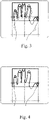
- Figs. 1-4 can be thought of as a method for positioning an anatomy for imaging, in which method a first partial volume is imaged first and a second partial volume after that. These partial volumes are imaged such that the mutual positioning of the anatomy and the imaging means is changed between the imagings. This change in the positioning can be implemented such that the first and the second partial volumes will partially cover a same volume of the anatomy being imaged, but the invention can also enable a controlled positioning of partial volumes such that the partial volumes do not intersect each other.
- a photograph or a still video image is taken of the anatomy positioned at the imaging station by a camera arranged in connection with the imaging station, which image is presented on the display as moved to a new position in relation to the imaging station ( Fig. 2 ). Then, this image and a real time image of the imaging station are presented on the display one upon another, and positioning of the anatomy being imaged ( Fig. 3 ) to meet the image of the first partial volume presented on the display as moved into the new position is observed from the display ( Fig. 4 ).
- Figs. 1-4 are not intended to show any particular embodiment of the invention but only to demonstrate the invention.
- the outermost rectangles of Figs. 1-4 plotted by a continuous line can be thought of as demonstrating a display screen, the area of the imaging area or of the imaging station seen by the camera, or the field of view (FOV) from which a tomographic image can be reconstructed using x-ray image information the imaging apparatus generates.
- FOV field of view
- Figs. 1-4 can in turn be thought of as relating to the image transfer process according to the invention such that the dashed line area of Fig. 1 represents an area (anatomy) of the image taken by the camera from the imaging station selected to be transferred, and Fig. 2 shows how the image taken of the area (anatomy) selected in Fig. 1 has been transferred (the area defined by the continuous line).
- Fig. 2 has been used as a base for Figs. 3 and 4 and hence they also include the area of Fig. 1 plotted by the dashed line. Concerning the steps shown in Figs. 3 and 4 , the area of Fig.
- Figs. 3 and 4 Essential to Figs. 3 and 4 is presenting the image taken during the phase shown in Fig. 1 , that is the image located at a transferred position according to Fig. 2 (the image shown within the area defined by the continuous line), on a display in a camera picture taken from the imaging area.
- the dashed line area of Fig. 1 can be considered presenting an area of the image taken by the camera selected to be transferred
- the camera has been arranged to photograph only the dashed line area, which picture as such will then be arranged to be shown on the display at a new position, If only this dashed line area is photographed and if only it is presented on the display during the steps which Figs. 3 and 4 present, the area of the anatomy whose positioning to a desired location can then be followed is correspondingly smaller.
- a controlled repositioning of the anatomy can also be made concerning partial volumes which do not intersect.
- a controlled repositioning of the anatomy can also be made concerning partial volumes which do not intersect.
- a controlled repositioning of the anatomy can also be made concerning partial volumes which do not intersect.
- the partial volume imaged according to step 4 locates in relation to the first partial volume imaged in the step according to Fig. 1 .
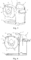
- the basic idea of the invention is preferable to be applied for example in an imaging apparatus according to Fig. 5 .
- the basic structure of the apparatus includes a support construction (1) which supports a substantially ring-shaped structure (2), inside which the x-ray imaging means (21, 22) of the apparatus are positioned and which in this context is also referred to as an O-arm.
- a support construction (1) which supports a substantially ring-shaped structure (2), inside which the x-ray imaging means (21, 22) of the apparatus are positioned and which in this context is also referred to as an O-arm.
- an examination opening (4) into which the anatomy to be imaged is positioned.
- FIG. 1 further shows a patient support handlebar (5) arranged to the support construction (1), a user interface (6) being in functional connection with a control system of the apparatus, a possibly detachably attached pedestal or base part (7) projecting substantially in the direction of the O-arm, and a positioning support (8) arranged in the examination opening (4).
- the display (11) belonging to the apparatus is arranged substantially on the surface of the ring-shaped structure (2), at its upper edge.
- Mounting of the structure (2) supporting the imaging means to the support construction (1) can be arranged to enable adjustment of the height position of the O-arm (2). Furthermore, this O-arm (2) can be arranged to be turnable in at least one direction for at least 90 degrees from the vertical position, shown in Pig. (1), to a horizontal position.
- the control of these manoeuvres can be arranged implementa-ble, aside from the user interface (6) being connected with the control system of the apparatus also by means of a joy stick (9) arranged in connection with the O-arm (2) and/or the support frame (1).
- Fig. 6 shows two alternative ways to position the display (11) in connection with the apparatus.
- the display is preferably positioned to the apparatus at a location which is visible to the patient when e.g. a patient's leg is being imaged.
- the display (11) can be arranged to the ring-shaped structure (2) both as fixed and as movably attached.
- the connection can be arranged to enable either adjusting orientation of the display (11) with respect to the ring-shaped structure (2), adjusting clearance and/or location of the display (11) with respect to the ring-shaped structure (2), or it can be arranged with some or all of these degrees of freedom of movement.
- the display (11) can be attached to the supporting structure (1), or a separate display (11) can be set to the supporting structure (1) which display (11) can be arranged with the degrees of freedom of movement as described above but with respect to the supporting structure (1).
- a video camera (12) aligned inside the examination opening (4) is arranged in connection with the ring-shaped structure (2) of the .
- the camera (12) can be arranged to the ring-shaped structure (2) outside its cover, particularly at the opposite side of the examination opening from which the extremity to be imaged is designed to be brought into the examination opening, but in a preferable embodiment of the invention the video camera (12) is arranged inside the ring-shaped structure (2) and at least a part of an inner surface of the said ring-shaped structure (2) is arranged transparent or to comprise an opening through which the camera (12) is aligned at the examination opening (4), like substantially at a positioning support (8) arranged in the examination opening,
- the apparatus has at least one photography or video camera (12) which is arranged to image an imaging area of the apparatus and the control system of the apparatus presents on a display (11) one upon another a first image taken of an object positioned for tomographic imaging and an essentially real time image taken of the imaging area such that the object visible in the first image positioned for tomography imaging is moved to a position in the imaging area different from where it was in when the first image was taken.
- the camera can be arranged inside the ring-shaped structure (2) and at least part of an inner surface of the ring-shaped structure (2) is arranged transparent or to contain an opening through which the camera (12) is aligned or can be aligned at the examination opening (4). If there is a positioning support (8) arranged in the examination opening (4) for positioning an anatomy to be imaged for x-ray imaging, the camera (12) is preferably aligned or arranged to be aligned substantially at the positioning support (8).
Description
- The invention relates to mutual positioning of partial volumes of an anatomy in connection with an imaging process,
- Conventional apparatuses employed in medical x-ray imaging which are most simple as for their basic structure comprise a source of radiation which is used together with a film cassette separate from the source of radiation. Hospitals commonly also use so-called C-arch x-ray apparatuses in which the source of radiation and the receiver of image information are arranged at the opposite ends of the archshaped arm part. Conventionally, a group of apparatus completely of its own consists of large-size and extremely expensive computed tomography apparatus, into which a patient is typically positioned for imaging in a lying position inside a ring-shaped or tubular structure.
- As conventional computed tomography apparatus have been quite massive and expensive, acquiring them e.g. for the use of hospital emergency rooms has not been possible in practice. On the other hand, it has also been typical for commercial computed tomography apparatus that they are not necessarily designed for imaging some specific anatomy or anatomies but they are more or less general imaging apparatus. If one wishes to image e.g. the patient's whole torso, the imaging station arranged to the apparatus as well as other dimensions of the apparatus must have been implemented in respective proportions.
- More lightweight computed tomography apparatus versions have bean developed as well. As an example of prior art solutions, a reference can be made to a structure disclosed e.g. in the MO publication 2011/135186. In such apparatus, imaging means arranged to move around an imaging station are arranged within a ring-shaped O-arm, supported from its side.
- In the more lightweight apparatus according to the prior art as referred to above cone beam tomography (CBCT) may be used. There, one criterion which limits the size of a volume getting imaged (FOV - Field of View) is the dimensions of the imaging detector, which for obvious reasons cannot be arranged in such context to be very large, When considering imaging an extremity, for example, it is clear that when using such an imaging apparatus it is possible to image only a single partial volume of the extremity by one mutual positioning of the patient and the imaging apparatus. Then it becomes necessary to position the anatomy in the imaging apparatus anew, for imaging the next partial volume, and realizing the re-positioning in relation to the previous positioning in an exactly desired way can be a chal-
-
WO2014/027312 , which is an Art. 54(3) EPC document relevant only for novelty, discloses a movable X-ray imaging apparatus for aligning an object of interest relative to an X-ray imaging arrangement, which has a display that shows a graphical representation of a reference point overlaid with a camera image to guide alignment of the X-ray source or the X-ray detector. - The invention is defined by the
independent claims - The object of the present invention is to advance the state of the art concerning e.g. the less expensive and smaller x-ray imaging apparatus like those referred to above. A special object of the invention is to advance development particularly regarding x-ray imaging apparatus of the above-described type comprising a ring-shaped arm part and being of relatively small size. The construction, characteristics and dimensions of such apparatus remarkably differ in many respects from the conventional hospital computed tomography apparatus and in these apparatus the patient is positioned for imaging in a way other than in conventional computed tomography apparatus, in which the patient is set to lay down on an imaging platform.
- Especially an object of the invention is an arrangement which eases positioning of a patient in situations in which one needs to image an anatomy at more than one location so as to get the entire desired volume imaged.
- Essential features of the invention are described in the accompanying claims. Especially essential for the invention is to arrange a means to the imaging apparatus to take photographs or video images of the imaging area of the apparatus and, on the other hand, a means to present such camera image on a display in a specific way.
- The invention facilitates positioning of a patient and can make it unnecessary to use e.g. scout x-ray images, which are taken by using a small radiation dose, for positioning purposes.. The invention can also be arranged to speed up processing of image information to combine the partial volumes imaged after the imaging, as there is at least moderately accurate information available regarding how the sets of coordinates of the partial volumes imaged have located in relation to each other.
- Next, the invention and its preferable embodiments will be described in more detail and also with reference to the enclosed figures.
-
-
Fig. 1 shows photographing a first partial volume of an object positioned in an imaging area of an imaging apparatus. -
Fig. 2 shows an image in which the image shown inFig. 1 , taken when the object is located at an imaging position for the first partial volume, is projected as placed in a new desired location considering imaging the next partial volume. -
Fig. 3 demonstrates an image being presented on a display in which the object being imaged is being positioned at a new location for imaging the next partial volume. -
Fig. 4 demonstrates a situation in which the object has been managed to be positioned at the new location for imaging the next partial volume. -
Figs. 5 and 6 show solutions for apparatus applicable for use in the invention. -
Fig. 7 shows, as simplified, how the structure according toFigs. 5 and 6 can be arranged with a camera aligned at the imaging area of the apparatus. - The process demonstrated by
Figs. 1-4 can be thought of as a method for positioning an anatomy for imaging, in which method a first partial volume is imaged first and a second partial volume after that. These partial volumes are imaged such that the mutual positioning of the anatomy and the imaging means is changed between the imagings. This change in the positioning can be implemented such that the first and the second partial volumes will partially cover a same volume of the anatomy being imaged, but the invention can also enable a controlled positioning of partial volumes such that the partial volumes do not intersect each other. - During imaging of the first partial volume (
Fig. 1 ), a photograph or a still video image is taken of the anatomy positioned at the imaging station by a camera arranged in connection with the imaging station, which image is presented on the display as moved to a new position in relation to the imaging station (Fig. 2 ). Then, this image and a real time image of the imaging station are presented on the display one upon another, and positioning of the anatomy being imaged (Fig. 3 ) to meet the image of the first partial volume presented on the display as moved into the new position is observed from the display (Fig. 4 ). -
Figs. 1-4 are not intended to show any particular embodiment of the invention but only to demonstrate the invention. Thus, e.g. the outermost rectangles ofFigs. 1-4 plotted by a continuous line can be thought of as demonstrating a display screen, the area of the imaging area or of the imaging station seen by the camera, or the field of view (FOV) from which a tomographic image can be reconstructed using x-ray image information the imaging apparatus generates. - The smaller rectangular areas of
Figs. 1-4 can in turn be thought of as relating to the image transfer process according to the invention such that the dashed line area ofFig. 1 represents an area (anatomy) of the image taken by the camera from the imaging station selected to be transferred, andFig. 2 shows how the image taken of the area (anatomy) selected inFig. 1 has been transferred (the area defined by the continuous line).Fig. 2 has been used as a base forFigs. 3 and 4 and hence they also include the area ofFig. 1 plotted by the dashed line. Concerning the steps shown inFigs. 3 and 4 , the area ofFig. 1 plotted by the dashed line has no particular function but to demonstrate the process, also that area is carried over toFigs. 3 and 4 . Essential toFigs. 3 and 4 is presenting the image taken during the phase shown inFig. 1 , that is the image located at a transferred position according toFig. 2 (the image shown within the area defined by the continuous line), on a display in a camera picture taken from the imaging area. - When it was noted above that the dashed line area of
Fig. 1 can be considered presenting an area of the image taken by the camera selected to be transferred, it is also possible to consider that the camera has been arranged to photograph only the dashed line area, which picture as such will then be arranged to be shown on the display at a new position, If only this dashed line area is photographed and if only it is presented on the display during the steps whichFigs. 3 and 4 present, the area of the anatomy whose positioning to a desired location can then be followed is correspondingly smaller. - Within limits the camera arrangement of an apparatus and the dimensions of its imaging area allow for, a controlled repositioning of the anatomy can also be made concerning partial volumes which do not intersect. Considering e.g. a situation in which there are two points of interest in an extremity, located at distance from each other and including a partial volume in-between regarding which there is no need to acquire actual x-ray image information. As one knows when proceeding as described above how the photograph taken during the step according to
Fig. 1 has been transferred to the location according toFig.2 , one also knows where the partial volume imaged according tostep 4 locates in relation to the first partial volume imaged in the step according toFig. 1 . - The basic idea of the invention is preferable to be applied for example in an imaging apparatus according to
Fig. 5 . The basic structure of the apparatus includes a support construction (1) which supports a substantially ring-shaped structure (2), inside which the x-ray imaging means (21, 22) of the apparatus are positioned and which in this context is also referred to as an O-arm. To this O-arm (2) is arranged an examination opening (4) into which the anatomy to be imaged is positioned.Fig. 1 further shows a patient support handlebar (5) arranged to the support construction (1), a user interface (6) being in functional connection with a control system of the apparatus, a possibly detachably attached pedestal or base part (7) projecting substantially in the direction of the O-arm, and a positioning support (8) arranged in the examination opening (4). According to the embodiment of the invention shown inFig. 1 , the display (11) belonging to the apparatus is arranged substantially on the surface of the ring-shaped structure (2), at its upper edge. - Mounting of the structure (2) supporting the imaging means to the support construction (1) can be arranged to enable adjustment of the height position of the O-arm (2). Furthermore, this O-arm (2) can be arranged to be turnable in at least one direction for at least 90 degrees from the vertical position, shown in Pig. (1), to a horizontal position. The control of these manoeuvres can be arranged implementa-ble, aside from the user interface (6) being connected with the control system of the apparatus also by means of a joy stick (9) arranged in connection with the O-arm (2) and/or the support frame (1).
-
Fig. 6 shows two alternative ways to position the display (11) in connection with the apparatus. The display is preferably positioned to the apparatus at a location which is visible to the patient when e.g. a patient's leg is being imaged. The display (11) can be arranged to the ring-shaped structure (2) both as fixed and as movably attached. The connection can be arranged to enable either adjusting orientation of the display (11) with respect to the ring-shaped structure (2), adjusting clearance and/or location of the display (11) with respect to the ring-shaped structure (2), or it can be arranged with some or all of these degrees of freedom of movement. Alternatively, the display (11) can be attached to the supporting structure (1), or a separate display (11) can be set to the supporting structure (1) which display (11) can be arranged with the degrees of freedom of movement as described above but with respect to the supporting structure (1). - In the embodiment presented in
Fig, 7 , a video camera (12) aligned inside the examination opening (4) is arranged in connection with the ring-shaped structure (2) of the . In principle, the camera (12) can be arranged to the ring-shaped structure (2) outside its cover, particularly at the opposite side of the examination opening from which the extremity to be imaged is designed to be brought into the examination opening, but in a preferable embodiment of the invention the video camera (12) is arranged inside the ring-shaped structure (2) and at least a part of an inner surface of the said ring-shaped structure (2) is arranged transparent or to comprise an opening through which the camera (12) is aligned at the examination opening (4), like substantially at a positioning support (8) arranged in the examination opening, - However, it is essential that the apparatus has at least one photography or video camera (12) which is arranged to image an imaging area of the apparatus and the control system of the apparatus presents on a display (11) one upon another a first image taken of an object positioned for tomographic imaging and an essentially real time image taken of the imaging area such that the object visible in the first image positioned for tomography imaging is moved to a position in the imaging area different from where it was in when the first image was taken. The camera can be arranged inside the ring-shaped structure (2) and at least part of an inner surface of the ring-shaped structure (2) is arranged transparent or to contain an opening through which the camera (12) is aligned or can be aligned at the examination opening (4). If there is a positioning support (8) arranged in the examination opening (4) for positioning an anatomy to be imaged for x-ray imaging, the camera (12) is preferably aligned or arranged to be aligned substantially at the positioning support (8).
Claims (5)
- Method for positioning an anatomy for imaging, wherein the positioning comprises positioning the anatomy for tomographic imaging by a tomographic imaging apparatus, which tomographic imaging comprises i) a first imaging of first partial volume of the anatomy while the anatomy is positioned at an imaging station of the tomographic imaging apparatus and ii) after that a second imaging of a second partial volume of the anatomy by said tomographic imaging apparatus while the anatomy is positioned at the imaging station of the tomographic imaging apparatus, wherein in connection with the tomographic imaging of the first partial volume of the anatomy, also a photograph or a still video image of the anatomy positioned at the imaging station is taken by a camera arranged in connection with the imaging station so as to generate a first image of the anatomy positioned for tomographic imaging and wherein, for positioning the anatomy for imaging the second partial volume, on a display is presented, one upon another i) a real time image of the imaging station and ii) said first image, said first image being presented as moved into a new position in relation to the imaging station so as to enable observing, from the display, the positioning of the anatomy at the imaging station to meet the first partial volume in the first image, which is now being presented on the display as moved into the new position.
- The method according to claim 1, wherein between the imaging of the first and the second partial volume, mutual positioning of the anatomy and the imaging station is changed such that the first and the second partial volumes partially cover the same partial volume of the anatomy being imaged.
- Medical imaging apparatus, wherein the apparatus is a computed tomography imaging apparatus which includes- a support construction (1), which is arranged to support a substantially ring-shaped structure (2) supporting imaging means, which imaging means include a source of radiation (21) and a receiver of image information (22), which imaging means are arranged inside said substantially ring-shaped structure (2) supporting the imaging means substantially on opposite sides, and to be moved inside said ring-shaped structure (2) supporting the imaging means,- a control system for controlling at least some of the functions of the apparatus,- which apparatus includes in said ring-shaped structure (2) supporting the imaging means an examination opening (4), in which an anatomy to be imaged is positionable for imaging,which apparatus is arranged with at least one photography or video camera (12) and at least one display (11) arranged in functional connection with said at least one photography or video camera (12), which at least one photography or video camera (12) is arranged in connection with said substantially ring-shaped structure (2) and is aligned or to be aligned inside said examination opening (4), wherein said at least one photography or video camera (12) is arranged to image an imaging area of the apparatus and the control system of the apparatus to present on said at least one display (11), one upon another,i) a first image taken of the anatomy positioned within the imaging area for tomographic imaging andii) an essentially real time image taken by said at least one photography or video camera (12) of said imaging area,which presenting by the control system comprises presenting, in a view on said at least one display (11), said first image and said real time image such that the anatomy, visible in said first image when it was positioned for tomographic imaging, has been moved within the imaging area into a position which is different from the position where it was when the first image was taken.
- The imaging apparatus according to claim 3, wherein said at least one camera is arranged inside said substantially ring-shaped structure (2) and at least a portion of an inner surface of said substantially ring-shaped structure (2) has been arranged transparent or comprises an opening through which said at least one camera is aligned or can be aligned at said examination opening (4).
- The imaging apparatus according to claim 3 or 4, wherein a positioning support (8) is arranged in said examination opening (4) for positioning the anatomy to be imaged for x-ray imaging and said at least one camera (12) is aligned or arranged to be aligned substantially at said positioning support (8).
Applications Claiming Priority (2)
| Application Number | Priority Date | Filing Date | Title |
|---|---|---|---|
| FI20130362A FI125206B (en) | 2013-11-29 | 2013-11-29 | Location of anatomical partial volumes |
| PCT/FI2014/050938 WO2015079121A1 (en) | 2013-11-29 | 2014-12-01 | Positioning of partial volumes of an anatomy |
Publications (3)
| Publication Number | Publication Date |
|---|---|
| EP3073928A1 EP3073928A1 (en) | 2016-10-05 |
| EP3073928A4 EP3073928A4 (en) | 2017-08-02 |
| EP3073928B1 true EP3073928B1 (en) | 2022-10-05 |
Family
ID=53198423
Family Applications (1)
| Application Number | Title | Priority Date | Filing Date |
|---|---|---|---|
| EP14865068.2A Active EP3073928B1 (en) | 2013-11-29 | 2014-12-01 | Positioning of partial volumes of an anatomy |
Country Status (8)
| Country | Link |
|---|---|
| US (1) | US10213170B2 (en) |
| EP (1) | EP3073928B1 (en) |
| JP (1) | JP6518250B2 (en) |
| KR (1) | KR102150143B1 (en) |
| CN (1) | CN106132306B (en) |
| ES (1) | ES2928185T3 (en) |
| FI (1) | FI125206B (en) |
| WO (1) | WO2015079121A1 (en) |
Families Citing this family (2)
| Publication number | Priority date | Publication date | Assignee | Title |
|---|---|---|---|---|
| EP3326532B1 (en) * | 2015-07-21 | 2020-01-01 | Fujifilm Corporation | Radiation exposure device, and control method and program for radiation exposure device |
| EP3360482A1 (en) * | 2017-02-09 | 2018-08-15 | Koninklijke Philips N.V. | Iso-centering in c-arm computer tomography |
Family Cites Families (16)
| Publication number | Priority date | Publication date | Assignee | Title |
|---|---|---|---|---|
| JPH01181849A (en) * | 1988-01-13 | 1989-07-19 | Toshiba Corp | Body surface image processor |
| US6279579B1 (en) * | 1998-10-23 | 2001-08-28 | Varian Medical Systems, Inc. | Method and system for positioning patients for medical treatment procedures |
| DE10046091C1 (en) * | 2000-09-18 | 2002-01-17 | Siemens Ag | Computer tomography device has optical imaging device providing visual images of area of patient examined via X-ray beam |
| US7016522B2 (en) | 2002-01-15 | 2006-03-21 | Siemens Medical Solutions Usa, Inc. | Patient positioning by video imaging |
| DE10210050A1 (en) * | 2002-03-07 | 2003-12-04 | Siemens Ag | Method and device for repetitive relative positioning of a patient |
| US6895076B2 (en) * | 2003-06-03 | 2005-05-17 | Ge Medical Systems Global Technology Company, Llc | Methods and apparatus for multiple image acquisition on a digital detector |
| DE102005020124B4 (en) * | 2005-04-29 | 2011-07-14 | Siemens AG, 80333 | X-ray system comprising an associated, mobile solid-state detector and method for recording and displaying an X-ray image |
| DE102007034218B4 (en) * | 2007-07-23 | 2013-06-13 | Siemens Aktiengesellschaft | Apparatus and method for image composition |
| DE102007061592B4 (en) * | 2007-12-20 | 2010-03-18 | Siemens Ag | Method for positioning the breast for a biopsy in a mammography device and mammography device for performing the method |
| DE102008035412A1 (en) * | 2008-07-29 | 2010-02-04 | Sirona Dental Systems Gmbh | Method for producing a dental 3D X-ray image and X-ray device therefor |
| CN101884544B (en) * | 2009-05-12 | 2014-12-10 | Ge医疗系统环球技术有限公司 | Image acquisition method, device and X-ray filming machine |
| FI125531B (en) | 2010-04-29 | 2015-11-13 | Planmed Oy | Medical x-ray equipment |
| CN102958436A (en) | 2010-07-30 | 2013-03-06 | 富士胶片株式会社 | Radiograph imaging system, radiograph imaging method, and image display method |
| DE102011005777B4 (en) | 2011-03-18 | 2018-04-26 | Siemens Healthcare Gmbh | Angiography system for angiographic examination of a patient and angiographic examination procedure |
| DE102011006991B4 (en) | 2011-04-07 | 2018-04-05 | Siemens Healthcare Gmbh | X-ray method and X-ray device for assembling X-ray images and determining three-dimensional volume data |
| RU2641833C2 (en) * | 2012-08-17 | 2018-01-22 | Конинклейке Филипс Н.В. | Visual adjustment of mobile x-ray imaging system with camera |
-
2013
- 2013-11-29 FI FI20130362A patent/FI125206B/en active IP Right Grant
-
2014
- 2014-12-01 WO PCT/FI2014/050938 patent/WO2015079121A1/en active Application Filing
- 2014-12-01 KR KR1020167013840A patent/KR102150143B1/en active IP Right Grant
- 2014-12-01 JP JP2016533712A patent/JP6518250B2/en active Active
- 2014-12-01 ES ES14865068T patent/ES2928185T3/en active Active
- 2014-12-01 US US15/037,787 patent/US10213170B2/en active Active
- 2014-12-01 CN CN201480065252.0A patent/CN106132306B/en active Active
- 2014-12-01 EP EP14865068.2A patent/EP3073928B1/en active Active
Also Published As
| Publication number | Publication date |
|---|---|
| KR20160091334A (en) | 2016-08-02 |
| US10213170B2 (en) | 2019-02-26 |
| US20160296180A1 (en) | 2016-10-13 |
| JP6518250B2 (en) | 2019-05-22 |
| EP3073928A4 (en) | 2017-08-02 |
| FI125206B (en) | 2015-07-15 |
| WO2015079121A1 (en) | 2015-06-04 |
| CN106132306A8 (en) | 2017-04-19 |
| KR102150143B1 (en) | 2020-09-01 |
| ES2928185T3 (en) | 2022-11-16 |
| EP3073928A1 (en) | 2016-10-05 |
| JP2016538065A (en) | 2016-12-08 |
| CN106132306A (en) | 2016-11-16 |
| CN106132306B (en) | 2019-10-18 |
Similar Documents
| Publication | Publication Date | Title |
|---|---|---|
| EP2600769B1 (en) | Medical computed tomography imaging apparatus | |
| WO2013005833A1 (en) | X-ray imaging device and calibration method therefor | |
| US7845851B2 (en) | Low-dose iso-centering | |
| US10687771B2 (en) | X-ray diagnostic apparatus comprising a position specifying unit and a control unit | |
| EP2767236A1 (en) | X-ray collimator size and position adjustment based on pre-shot | |
| CN107106099B (en) | Imaging system for imaging an elongated region of interest of an object | |
| JP2016131573A (en) | Control device of tomosynthesis imaging, radiographic device, control system, control method, and program | |
| US20170290559A1 (en) | Mobile x-ray machine | |
| JP6970203B2 (en) | Computed tomography and positioning of anatomical structures to be imaged | |
| JP6075439B2 (en) | X-ray equipment | |
| EP3073928B1 (en) | Positioning of partial volumes of an anatomy | |
| US6302580B1 (en) | Apparatus for solid state digital imager tracking radiography | |
| US20160073998A1 (en) | X-ray diagnostic apparatus | |
| JP6878455B2 (en) | Medical image orientation | |
| JP2013017675A (en) | X-ray imaging device and calibration method therefor | |
| JP2012050605A (en) | X-ray image photographing apparatus, the x-ray image photographing method, and program | |
| KR101577563B1 (en) | X-ray Detector Module with Medical Diagnostic Ruler. | |
| EP3579756B1 (en) | Iso-centering in c-arm computer tomography | |
| JP7283470B2 (en) | radiography equipment | |
| JP2016198277A (en) | Control device for tomosynthesis imaging, radiographic system, control system, control method, and program | |
| US20220280125A1 (en) | X-ray bed | |
| JP2003010164A (en) | X-ray equipment | |
| JP2005253572A (en) | Image processor, x-ray diagnosis apparatus, medical image information system and calibration table attaching method | |
| JP2009240477A (en) | Radiation image capturing apparatus, method and program | |
| JP2006000222A (en) | X-ray ct apparatus |
Legal Events
| Date | Code | Title | Description |
|---|---|---|---|
| PUAI | Public reference made under article 153(3) epc to a published international application that has entered the european phase |
Free format text: ORIGINAL CODE: 0009012 |
|
| STAA | Information on the status of an ep patent application or granted ep patent |
Free format text: STATUS: REQUEST FOR EXAMINATION WAS MADE |
|
| 17P | Request for examination filed |
Effective date: 20160628 |
|
| AK | Designated contracting states |
Kind code of ref document: A1 Designated state(s): AL AT BE BG CH CY CZ DE DK EE ES FI FR GB GR HR HU IE IS IT LI LT LU LV MC MK MT NL NO PL PT RO RS SE SI SK SM TR |
|
| AX | Request for extension of the european patent |
Extension state: BA ME |
|
| DAX | Request for extension of the european patent (deleted) | ||
| A4 | Supplementary search report drawn up and despatched |
Effective date: 20170629 |
|
| RIC1 | Information provided on ipc code assigned before grant |
Ipc: A61B 6/03 20060101ALI20170623BHEP Ipc: A61B 6/08 20060101ALI20170623BHEP Ipc: G01N 23/04 20060101ALI20170623BHEP Ipc: G06T 7/00 20170101ALI20170623BHEP Ipc: A61B 6/00 20060101AFI20170623BHEP |
|
| STAA | Information on the status of an ep patent application or granted ep patent |
Free format text: STATUS: EXAMINATION IS IN PROGRESS |
|
| 17Q | First examination report despatched |
Effective date: 20210326 |
|
| STAA | Information on the status of an ep patent application or granted ep patent |
Free format text: STATUS: EXAMINATION IS IN PROGRESS |
|
| GRAP | Despatch of communication of intention to grant a patent |
Free format text: ORIGINAL CODE: EPIDOSNIGR1 |
|
| STAA | Information on the status of an ep patent application or granted ep patent |
Free format text: STATUS: GRANT OF PATENT IS INTENDED |
|
| INTG | Intention to grant announced |
Effective date: 20220331 |
|
| RAP3 | Party data changed (applicant data changed or rights of an application transferred) |
Owner name: PLANMED OY |
|
| RIN1 | Information on inventor provided before grant (corrected) |
Inventor name: LAUKKANEN, TAPIO Inventor name: MALM, JUHAMATTI |
|
| GRAS | Grant fee paid |
Free format text: ORIGINAL CODE: EPIDOSNIGR3 |
|
| GRAA | (expected) grant |
Free format text: ORIGINAL CODE: 0009210 |
|
| STAA | Information on the status of an ep patent application or granted ep patent |
Free format text: STATUS: THE PATENT HAS BEEN GRANTED |
|
| AK | Designated contracting states |
Kind code of ref document: B1 Designated state(s): AL AT BE BG CH CY CZ DE DK EE ES FI FR GB GR HR HU IE IS IT LI LT LU LV MC MK MT NL NO PL PT RO RS SE SI SK SM TR |
|
| REG | Reference to a national code |
Ref country code: GB Ref legal event code: FG4D |
|
| REG | Reference to a national code |
Ref country code: CH Ref legal event code: EP |
|
| REG | Reference to a national code |
Ref country code: AT Ref legal event code: REF Ref document number: 1522239 Country of ref document: AT Kind code of ref document: T Effective date: 20221015 |
|
| REG | Reference to a national code |
Ref country code: IE Ref legal event code: FG4D |
|
| REG | Reference to a national code |
Ref country code: DE Ref legal event code: R096 Ref document number: 602014085167 Country of ref document: DE |
|
| REG | Reference to a national code |
Ref country code: ES Ref legal event code: FG2A Ref document number: 2928185 Country of ref document: ES Kind code of ref document: T3 Effective date: 20221116 |
|
| REG | Reference to a national code |
Ref country code: LT Ref legal event code: MG9D |
|
| PGFP | Annual fee paid to national office [announced via postgrant information from national office to epo] |
Ref country code: IT Payment date: 20221122 Year of fee payment: 9 |
|
| REG | Reference to a national code |
Ref country code: NL Ref legal event code: MP Effective date: 20221005 |
|
| REG | Reference to a national code |
Ref country code: AT Ref legal event code: MK05 Ref document number: 1522239 Country of ref document: AT Kind code of ref document: T Effective date: 20221005 |
|
| PG25 | Lapsed in a contracting state [announced via postgrant information from national office to epo] |
Ref country code: NL Free format text: LAPSE BECAUSE OF FAILURE TO SUBMIT A TRANSLATION OF THE DESCRIPTION OR TO PAY THE FEE WITHIN THE PRESCRIBED TIME-LIMIT Effective date: 20221005 |
|
| PG25 | Lapsed in a contracting state [announced via postgrant information from national office to epo] |
Ref country code: SE Free format text: LAPSE BECAUSE OF FAILURE TO SUBMIT A TRANSLATION OF THE DESCRIPTION OR TO PAY THE FEE WITHIN THE PRESCRIBED TIME-LIMIT Effective date: 20221005 Ref country code: PT Free format text: LAPSE BECAUSE OF FAILURE TO SUBMIT A TRANSLATION OF THE DESCRIPTION OR TO PAY THE FEE WITHIN THE PRESCRIBED TIME-LIMIT Effective date: 20230206 Ref country code: NO Free format text: LAPSE BECAUSE OF FAILURE TO SUBMIT A TRANSLATION OF THE DESCRIPTION OR TO PAY THE FEE WITHIN THE PRESCRIBED TIME-LIMIT Effective date: 20230105 Ref country code: LT Free format text: LAPSE BECAUSE OF FAILURE TO SUBMIT A TRANSLATION OF THE DESCRIPTION OR TO PAY THE FEE WITHIN THE PRESCRIBED TIME-LIMIT Effective date: 20221005 Ref country code: FI Free format text: LAPSE BECAUSE OF FAILURE TO SUBMIT A TRANSLATION OF THE DESCRIPTION OR TO PAY THE FEE WITHIN THE PRESCRIBED TIME-LIMIT Effective date: 20221005 Ref country code: AT Free format text: LAPSE BECAUSE OF FAILURE TO SUBMIT A TRANSLATION OF THE DESCRIPTION OR TO PAY THE FEE WITHIN THE PRESCRIBED TIME-LIMIT Effective date: 20221005 |
|
| PGFP | Annual fee paid to national office [announced via postgrant information from national office to epo] |
Ref country code: ES Payment date: 20230102 Year of fee payment: 9 |
|
| PG25 | Lapsed in a contracting state [announced via postgrant information from national office to epo] |
Ref country code: RS Free format text: LAPSE BECAUSE OF FAILURE TO SUBMIT A TRANSLATION OF THE DESCRIPTION OR TO PAY THE FEE WITHIN THE PRESCRIBED TIME-LIMIT Effective date: 20221005 Ref country code: PL Free format text: LAPSE BECAUSE OF FAILURE TO SUBMIT A TRANSLATION OF THE DESCRIPTION OR TO PAY THE FEE WITHIN THE PRESCRIBED TIME-LIMIT Effective date: 20221005 Ref country code: LV Free format text: LAPSE BECAUSE OF FAILURE TO SUBMIT A TRANSLATION OF THE DESCRIPTION OR TO PAY THE FEE WITHIN THE PRESCRIBED TIME-LIMIT Effective date: 20221005 Ref country code: IS Free format text: LAPSE BECAUSE OF FAILURE TO SUBMIT A TRANSLATION OF THE DESCRIPTION OR TO PAY THE FEE WITHIN THE PRESCRIBED TIME-LIMIT Effective date: 20230205 Ref country code: HR Free format text: LAPSE BECAUSE OF FAILURE TO SUBMIT A TRANSLATION OF THE DESCRIPTION OR TO PAY THE FEE WITHIN THE PRESCRIBED TIME-LIMIT Effective date: 20221005 Ref country code: GR Free format text: LAPSE BECAUSE OF FAILURE TO SUBMIT A TRANSLATION OF THE DESCRIPTION OR TO PAY THE FEE WITHIN THE PRESCRIBED TIME-LIMIT Effective date: 20230106 |
|
| REG | Reference to a national code |
Ref country code: DE Ref legal event code: R097 Ref document number: 602014085167 Country of ref document: DE |
|
| PG25 | Lapsed in a contracting state [announced via postgrant information from national office to epo] |
Ref country code: SM Free format text: LAPSE BECAUSE OF FAILURE TO SUBMIT A TRANSLATION OF THE DESCRIPTION OR TO PAY THE FEE WITHIN THE PRESCRIBED TIME-LIMIT Effective date: 20221005 Ref country code: RO Free format text: LAPSE BECAUSE OF FAILURE TO SUBMIT A TRANSLATION OF THE DESCRIPTION OR TO PAY THE FEE WITHIN THE PRESCRIBED TIME-LIMIT Effective date: 20221005 Ref country code: EE Free format text: LAPSE BECAUSE OF FAILURE TO SUBMIT A TRANSLATION OF THE DESCRIPTION OR TO PAY THE FEE WITHIN THE PRESCRIBED TIME-LIMIT Effective date: 20221005 Ref country code: DK Free format text: LAPSE BECAUSE OF FAILURE TO SUBMIT A TRANSLATION OF THE DESCRIPTION OR TO PAY THE FEE WITHIN THE PRESCRIBED TIME-LIMIT Effective date: 20221005 Ref country code: CZ Free format text: LAPSE BECAUSE OF FAILURE TO SUBMIT A TRANSLATION OF THE DESCRIPTION OR TO PAY THE FEE WITHIN THE PRESCRIBED TIME-LIMIT Effective date: 20221005 |
|
| REG | Reference to a national code |
Ref country code: CH Ref legal event code: PL |
|
| PLBE | No opposition filed within time limit |
Free format text: ORIGINAL CODE: 0009261 |
|
| STAA | Information on the status of an ep patent application or granted ep patent |
Free format text: STATUS: NO OPPOSITION FILED WITHIN TIME LIMIT |
|
| REG | Reference to a national code |
Ref country code: BE Ref legal event code: MM Effective date: 20221231 |
|
| PG25 | Lapsed in a contracting state [announced via postgrant information from national office to epo] |
Ref country code: SK Free format text: LAPSE BECAUSE OF FAILURE TO SUBMIT A TRANSLATION OF THE DESCRIPTION OR TO PAY THE FEE WITHIN THE PRESCRIBED TIME-LIMIT Effective date: 20221005 Ref country code: LU Free format text: LAPSE BECAUSE OF NON-PAYMENT OF DUE FEES Effective date: 20221201 Ref country code: AL Free format text: LAPSE BECAUSE OF FAILURE TO SUBMIT A TRANSLATION OF THE DESCRIPTION OR TO PAY THE FEE WITHIN THE PRESCRIBED TIME-LIMIT Effective date: 20221005 |
|
| 26N | No opposition filed |
Effective date: 20230706 |
|
| PG25 | Lapsed in a contracting state [announced via postgrant information from national office to epo] |
Ref country code: LI Free format text: LAPSE BECAUSE OF NON-PAYMENT OF DUE FEES Effective date: 20221231 Ref country code: IE Free format text: LAPSE BECAUSE OF NON-PAYMENT OF DUE FEES Effective date: 20221201 Ref country code: CH Free format text: LAPSE BECAUSE OF NON-PAYMENT OF DUE FEES Effective date: 20221231 |
|
| PG25 | Lapsed in a contracting state [announced via postgrant information from national office to epo] |
Ref country code: SI Free format text: LAPSE BECAUSE OF FAILURE TO SUBMIT A TRANSLATION OF THE DESCRIPTION OR TO PAY THE FEE WITHIN THE PRESCRIBED TIME-LIMIT Effective date: 20221005 Ref country code: BE Free format text: LAPSE BECAUSE OF NON-PAYMENT OF DUE FEES Effective date: 20221231 |
|
| PGFP | Annual fee paid to national office [announced via postgrant information from national office to epo] |
Ref country code: GB Payment date: 20231121 Year of fee payment: 10 |
|
| PGFP | Annual fee paid to national office [announced via postgrant information from national office to epo] |
Ref country code: FR Payment date: 20231122 Year of fee payment: 10 Ref country code: DE Payment date: 20231121 Year of fee payment: 10 |
|
| PG25 | Lapsed in a contracting state [announced via postgrant information from national office to epo] |
Ref country code: HU Free format text: LAPSE BECAUSE OF FAILURE TO SUBMIT A TRANSLATION OF THE DESCRIPTION OR TO PAY THE FEE WITHIN THE PRESCRIBED TIME-LIMIT; INVALID AB INITIO Effective date: 20141201 |