EP3073157A1 - Hydrauliksystem mit ölentlüftung - Google Patents
Hydrauliksystem mit ölentlüftung Download PDFInfo
- Publication number
- EP3073157A1 EP3073157A1 EP16150426.1A EP16150426A EP3073157A1 EP 3073157 A1 EP3073157 A1 EP 3073157A1 EP 16150426 A EP16150426 A EP 16150426A EP 3073157 A1 EP3073157 A1 EP 3073157A1
- Authority
- EP
- European Patent Office
- Prior art keywords
- hydraulic
- hydraulic fluid
- venting
- drive
- suction
- Prior art date
- Legal status (The legal status is an assumption and is not a legal conclusion. Google has not performed a legal analysis and makes no representation as to the accuracy of the status listed.)
- Granted
Links
Images


Classifications
-
- F—MECHANICAL ENGINEERING; LIGHTING; HEATING; WEAPONS; BLASTING
- F16—ENGINEERING ELEMENTS AND UNITS; GENERAL MEASURES FOR PRODUCING AND MAINTAINING EFFECTIVE FUNCTIONING OF MACHINES OR INSTALLATIONS; THERMAL INSULATION IN GENERAL
- F16H—GEARING
- F16H61/00—Control functions within control units of change-speed- or reversing-gearings for conveying rotary motion ; Control of exclusively fluid gearing, friction gearing, gearings with endless flexible members or other particular types of gearing
- F16H61/38—Control of exclusively fluid gearing
- F16H61/40—Control of exclusively fluid gearing hydrostatic
- F16H61/4174—Control of venting, e.g. removing trapped air
-
- B—PERFORMING OPERATIONS; TRANSPORTING
- B60—VEHICLES IN GENERAL
- B60K—ARRANGEMENT OR MOUNTING OF PROPULSION UNITS OR OF TRANSMISSIONS IN VEHICLES; ARRANGEMENT OR MOUNTING OF PLURAL DIVERSE PRIME-MOVERS IN VEHICLES; AUXILIARY DRIVES FOR VEHICLES; INSTRUMENTATION OR DASHBOARDS FOR VEHICLES; ARRANGEMENTS IN CONNECTION WITH COOLING, AIR INTAKE, GAS EXHAUST OR FUEL SUPPLY OF PROPULSION UNITS IN VEHICLES
- B60K17/00—Arrangement or mounting of transmissions in vehicles
- B60K17/04—Arrangement or mounting of transmissions in vehicles characterised by arrangement, location or kind of gearing
- B60K17/10—Arrangement or mounting of transmissions in vehicles characterised by arrangement, location or kind of gearing of fluid gearing
- B60K17/105—Units comprising at least a part of the gearing and a torque-transmitting axle, e.g. transaxles
-
- B—PERFORMING OPERATIONS; TRANSPORTING
- B60—VEHICLES IN GENERAL
- B60K—ARRANGEMENT OR MOUNTING OF PROPULSION UNITS OR OF TRANSMISSIONS IN VEHICLES; ARRANGEMENT OR MOUNTING OF PLURAL DIVERSE PRIME-MOVERS IN VEHICLES; AUXILIARY DRIVES FOR VEHICLES; INSTRUMENTATION OR DASHBOARDS FOR VEHICLES; ARRANGEMENTS IN CONNECTION WITH COOLING, AIR INTAKE, GAS EXHAUST OR FUEL SUPPLY OF PROPULSION UNITS IN VEHICLES
- B60K17/00—Arrangement or mounting of transmissions in vehicles
- B60K17/30—Arrangement or mounting of transmissions in vehicles the ultimate propulsive elements, e.g. ground wheels, being steerable
-
- B—PERFORMING OPERATIONS; TRANSPORTING
- B60—VEHICLES IN GENERAL
- B60K—ARRANGEMENT OR MOUNTING OF PROPULSION UNITS OR OF TRANSMISSIONS IN VEHICLES; ARRANGEMENT OR MOUNTING OF PLURAL DIVERSE PRIME-MOVERS IN VEHICLES; AUXILIARY DRIVES FOR VEHICLES; INSTRUMENTATION OR DASHBOARDS FOR VEHICLES; ARRANGEMENTS IN CONNECTION WITH COOLING, AIR INTAKE, GAS EXHAUST OR FUEL SUPPLY OF PROPULSION UNITS IN VEHICLES
- B60K17/00—Arrangement or mounting of transmissions in vehicles
- B60K17/34—Arrangement or mounting of transmissions in vehicles for driving both front and rear wheels, e.g. four wheel drive vehicles
- B60K17/356—Arrangement or mounting of transmissions in vehicles for driving both front and rear wheels, e.g. four wheel drive vehicles having fluid or electric motor, for driving one or more wheels
-
- B—PERFORMING OPERATIONS; TRANSPORTING
- B66—HOISTING; LIFTING; HAULING
- B66F—HOISTING, LIFTING, HAULING OR PUSHING, NOT OTHERWISE PROVIDED FOR, e.g. DEVICES WHICH APPLY A LIFTING OR PUSHING FORCE DIRECTLY TO THE SURFACE OF A LOAD
- B66F9/00—Devices for lifting or lowering bulky or heavy goods for loading or unloading purposes
- B66F9/06—Devices for lifting or lowering bulky or heavy goods for loading or unloading purposes movable, with their loads, on wheels or the like, e.g. fork-lift trucks
- B66F9/065—Devices for lifting or lowering bulky or heavy goods for loading or unloading purposes movable, with their loads, on wheels or the like, e.g. fork-lift trucks non-masted
- B66F9/0655—Devices for lifting or lowering bulky or heavy goods for loading or unloading purposes movable, with their loads, on wheels or the like, e.g. fork-lift trucks non-masted with a telescopic boom
-
- B—PERFORMING OPERATIONS; TRANSPORTING
- B66—HOISTING; LIFTING; HAULING
- B66F—HOISTING, LIFTING, HAULING OR PUSHING, NOT OTHERWISE PROVIDED FOR, e.g. DEVICES WHICH APPLY A LIFTING OR PUSHING FORCE DIRECTLY TO THE SURFACE OF A LOAD
- B66F9/00—Devices for lifting or lowering bulky or heavy goods for loading or unloading purposes
- B66F9/06—Devices for lifting or lowering bulky or heavy goods for loading or unloading purposes movable, with their loads, on wheels or the like, e.g. fork-lift trucks
- B66F9/075—Constructional features or details
- B66F9/07513—Details concerning the chassis
- B66F9/07518—Fuel or oil tank arrangements
-
- E—FIXED CONSTRUCTIONS
- E02—HYDRAULIC ENGINEERING; FOUNDATIONS; SOIL SHIFTING
- E02F—DREDGING; SOIL-SHIFTING
- E02F3/00—Dredgers; Soil-shifting machines
- E02F3/04—Dredgers; Soil-shifting machines mechanically-driven
- E02F3/28—Dredgers; Soil-shifting machines mechanically-driven with digging tools mounted on a dipper- or bucket-arm, i.e. there is either one arm or a pair of arms, e.g. dippers, buckets
- E02F3/283—Dredgers; Soil-shifting machines mechanically-driven with digging tools mounted on a dipper- or bucket-arm, i.e. there is either one arm or a pair of arms, e.g. dippers, buckets with a single arm pivoted directly on the chassis
- E02F3/286—Dredgers; Soil-shifting machines mechanically-driven with digging tools mounted on a dipper- or bucket-arm, i.e. there is either one arm or a pair of arms, e.g. dippers, buckets with a single arm pivoted directly on the chassis telescopic or slidable
-
- E—FIXED CONSTRUCTIONS
- E02—HYDRAULIC ENGINEERING; FOUNDATIONS; SOIL SHIFTING
- E02F—DREDGING; SOIL-SHIFTING
- E02F9/00—Component parts of dredgers or soil-shifting machines, not restricted to one of the kinds covered by groups E02F3/00 - E02F7/00
- E02F9/08—Superstructures; Supports for superstructures
- E02F9/0808—Improving mounting or assembling, e.g. frame elements, disposition of all the components on the superstructures
-
- E—FIXED CONSTRUCTIONS
- E02—HYDRAULIC ENGINEERING; FOUNDATIONS; SOIL SHIFTING
- E02F—DREDGING; SOIL-SHIFTING
- E02F9/00—Component parts of dredgers or soil-shifting machines, not restricted to one of the kinds covered by groups E02F3/00 - E02F7/00
- E02F9/20—Drives; Control devices
- E02F9/22—Hydraulic or pneumatic drives
- E02F9/226—Safety arrangements, e.g. hydraulic driven fans, preventing cavitation, leakage, overheating
-
- F—MECHANICAL ENGINEERING; LIGHTING; HEATING; WEAPONS; BLASTING
- F15—FLUID-PRESSURE ACTUATORS; HYDRAULICS OR PNEUMATICS IN GENERAL
- F15B—SYSTEMS ACTING BY MEANS OF FLUIDS IN GENERAL; FLUID-PRESSURE ACTUATORS, e.g. SERVOMOTORS; DETAILS OF FLUID-PRESSURE SYSTEMS, NOT OTHERWISE PROVIDED FOR
- F15B21/00—Common features of fluid actuator systems; Fluid-pressure actuator systems or details thereof, not covered by any other group of this subclass
- F15B21/04—Special measures taken in connection with the properties of the fluid
- F15B21/044—Removal or measurement of undissolved gas, e.g. de-aeration, venting or bleeding
Definitions
- the invention relates to an oil ventilation system for hydraulic circuits according to the preamble of claim 1 and a use of such a system in loading vehicles with at least one variable-length lift arm according to the preamble of claim 13.
- the loading vehicle embodied as a so-called telescopic loader comprises a drive motor positioned transversely to the longitudinal direction of the loading vehicle, which is assigned to a support frame pointing in the longitudinal direction of the loading vehicle in an area opposite the driver's cab.
- the output shaft of the drive motor extends over this side rail structure in the driver's cab-side area and receives at the end of a hydraulic pump, which is connected via a line system with a hydraulic motor integrated in the drive train of the front and rear bogie.
- the hydraulic motor is designed so that it drives both the front suspension forming front axle and the rear suspension forming the rear axle and is encapsulated by the side rail for protection against ground contact.
- the hydraulic systems used in such loading vehicles, as well as in tractors and other mobile machines include - among other components - at least one hydraulic pump, a sump or a hydraulic reservoir / tank, hydraulic functions such as actuators or cylinders, and valve devices or valves Control valves controlling the communication between the hydraulic pump, the sump and the hydraulic function.
- Hydraulic reservoirs or tanks were used to store oil or hydraulic fluid and give the hydraulic fluid time to defoam, vent or degas hydraulic fluid. If the fluid is not adequately vented, the hydraulic pump is susceptible to cavitation damage and failures. Air or gas mixed hydraulic fluid in a hydraulic system can cause noise, cause a precipitous action of the hydraulic function, cause heat generation, and result in reduced component life.
- hydraulic fluid may be at least partially atomized as it flows out of a control valve outlet at excessive speed as the hydraulic fluid flows back to the sump or communicates with the sump. This causes the hydraulic fluid in the sump to be mixed or foamed with air.
- the hydraulic systems of the travel drives mobile work machines are also completely filled with hydraulic fluid, so that in this way the known foaming is counteracted.
- the housing of the hydrostatic components should not be filled with hydraulic oil, so that the efficiency deteriorating so-called splashing is prevented.
- a hydraulic motor assembly and hydraulically coupled with this hydraulic motor hydraulic fluid accumulator is such that the at least one hydraulic motor assembly is associated with a suction device for extracting the hydraulic fluid in such a way that the suction device by means of negative pressure hydraulic fluid the hydraulic motor assembly dissipates in the hydraulic fluid reservoir, it is ensured that even with high-speed hydraulic engine arrangements, a satisfactory oil vent is achieved.
- a structurally simple and compact designed air intake can be realized when the hydraulic motor assembly is connected via an air intake with an integrated into the hydraulic fluid accumulator air intake.
- the air suction device is designed as an air intake pipe and is positioned inclined in the vertical direction in the hydraulic fluid reservoir.
- the air intake line comprises a check valve whose passage is released in response to a defined negative pressure in the hydraulic motor assembly.
- the check valve is under spring preload, which requires an opening pressure of up to 1 bar, preferably 0.6 bar.
- this negative pressure area connect in the Hydraulic fluid contained bubbles small size very effective to larger air bubbles, which can eventually be more efficient and easier to separate from the hydraulic fluid.
- the suction device comprises at least one integrated into a suction hydraulic pump whose input shaft is mechanically coupled via a gear stage with the output shaft of the hydraulic motor assembly.
- a direction of travel independent operation of the working with negative pressure extraction device is achieved in that the hydraulic pump is integrated in the manner in the suction, that the inlet and outlet side of the hydraulic pump is associated with a check valve, wherein the check valves in parallel are connected to a shuttle valve and the shuttle valve opens or closes the access to the hydraulic fluid reservoir.
- a coupling of the venting effects with cleaning effects can be achieved in an advantageous embodiment of the invention in the simplest case, that the suction in the region between the hydraulic motor assembly and hydraulic pump of the suction device is associated with a filter device and the hydraulic fluid reservoir is executed closed and includes a Beeraus- and -eintrittsö Maschinen Maschinen.
- the loading vehicle of the drive motor and the at least one central gear in the longitudinal direction of the loading vehicle staggered to each other and mutually assigned to the drive train of the chassis of the support structure and the drive motor and a drive pump associated therewith form a common drive unit and this drive unit at least partially via the Drive train extends and the central transmission is integrated in such a way in the drive train that it covers at least partially, it is achieved that the drive train has a compact design, which allows an optimal center of gravity of the Verladehuss and at the same time the use of larger drive units for generating and transmitting large Drive power permits.
- the drive structure according to the invention can be used in telescopic loaders, forklifts and wheel loaders
- FIG. 1 shows schematically designed as a telescopic loader 2 Verladehus 1.
- a telescopic loader 2 Verladehus 1 In a conventional manner, designed as a support frame 3 supporting structure 4 takes in a central position on a telescopic lifting arm 5, the front side a per se known tool adapter 6 is assigned.
- the lifting arm 5 is pivotally mounted in its rear region of at least one arranged in support flanges 7 transverse to the direction FR pivot axis 8 and wherein the realization of the pivoting movement of the lifting arm 5 below one or more lifting cylinders 9 are assigned to the pivoting of the lifting arm by pressurization or pressure relief 5 allow about said pivot axis 8.
- the telescopic extension and retraction of the lifting arm 5 is realized in a known per se and therefore not shown manner by means of further lifting cylinder.
- the telescopic lifting arm 5 divides the loading vehicle 1 into a cabin-side area 10 in which the driver's cab 11 is assigned to the supporting frame 3 and a drive-side area 12 in which the drive motor 13 is received by the supporting frame 3.
- the support frame 3 takes in a conventional manner a front landing gear 14 formed by a front landing gear 15 and a rear axle 16 formed by a rear landing gear 17.
- the support structure 4 comprises a longitudinal member 19 which extends in the longitudinal direction 18 of the loading vehicle 1 and to which the front chassis 15 and the rear chassis 17 are fastened.
- both the front axle 14 and the rear axle 16 each take a so-called differential gear 20, 21, which is executed either unlockable or rigid, for driving the wheels 22.
- Each of the differential gear 20, 21 is coupled in accordance with the invention via mechanical sub-drive trains 23, 24 with a central gear 25.
- the partial drive cords 23, 24 can be designed as propeller shafts 26, 27 known per se. It is within the scope of the invention that the partial drive trains 23, 24 may also comprise hydraulic components for transmitting the drive energy.
- the central gear 25 has in the illustrated embodiment, two in the vehicle longitudinal direction 18 facing output shafts 28, 29 which are drivingly connected to the respective propeller shaft 26, 27.
- the central transmission 25 is also integrated into the support structure 4 such that its output-side region 30 is essentially integrated in the drive train 31 of the running gear 15, 17 formed by the partial drive trains 23, 24.
- the drive-side region 32 of the central transmission 25 comprises at least one input shaft 33 which is likewise aligned in the vehicle longitudinal direction 18. This results in an arrangement in which the input and output shafts 28, 29, 33 in the vehicle longitudinal direction for the central transmission 25 18 and are offset from one another transversely to the vehicle longitudinal direction 18.
- a hydraulic motor 34 is mounted to drive the central gear 25.
- the hydraulic motor 34 is flanged to the central gear 25 via screw connections.
- the central gear 25 is fixed in the cabin-side region 10 at least partially below the driver's cab 11 and near the front axle 14 on the support structure 4.
- the drive train 31 and the central transmission 25 are at least partially encapsulated by the longitudinal member 19 of the support frame 3. It is within the scope of the invention that the drive train 31 and the central gear 25 can also be completely encased by the longitudinal member 19. In this case, almost no contamination and collision-related wear occurs.
- the support structure 4 also receives the drive motor 13, which is supported in the illustrated embodiment via a support frame 35 on the longitudinal member 19 of the support frame 3.
- the drive motor 13 assumes a nearly central position between the trolleys 15, 17 of the telehandler 2.
- it is arranged offset in the longitudinal direction 18 of the telescopic loader 2 to the central gear 25 in the drive-side region 12 of the telescopic loader 2.
- the central gear 25 and the drive motor 13 to the drive train 31 of the chassis 15, 17 are mutually associated.
- the installation position of the drive motor 13 extends transversely to the longitudinal direction 18 of the telescopic loader 2, so that the output shaft 36 points in the direction of the drive train 31 of the trolleys 15,17.
- the output shaft 36 of the drive motor 13 receives in accordance with the invention a hydraulic pump 37, which is flanged on the drive motor 13 by means of screw connections and driven by the drive motor 13 via the output shaft 36 and the hydraulic pump 37 associated drive port 40.
- the hydraulic pump 37 of the drive motor 13 and the hydraulic motor 34 of the central gear 25 are connected to each other via a conduit system 38 for transmitting the hydraulic medium.
- the line system 38 advantageously consists of hose lines 39.
- the drive units 13, 25, 34 , 37 are arranged below the longitudinal member 19.
- the drive unit 41 formed by the drive motor 13 and the associated hydraulic pump 37 being arranged in the drive-side region 12 such that the drive unit 41 extends at least partially into the region of the drive train 31 of the carriages 15, 17, a compact embodiment of the entire system will be provided Drive structure of the Verladehuss possible, which also ensures that the permissible outer dimensions of the mobile machine (X) are not exceeded.
- the coupled to the central gear 25 hydraulic motor assembly 34 is also associated with the suction device 42 according to the invention, which discharges in a manner to be described in more detail by means of negative pressure hydraulic fluid 43 from the hydraulic motor assembly 34 into a hydraulic fluid reservoir 44.
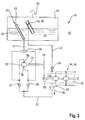
- FIG. 3 now shows the suction device 42 according to the invention in detail.
- the executed as a double motor 45 hydraulic motor assembly 34 is integrated into a housing 46.
- the housing 46 Via an air intake line 47, the housing 46 is connected to the hydraulic fluid reservoir 44.
- the hydraulic fluid reservoir 44 is only partially filled with hydraulic fluid 43, so that one of the air intake 47 associated air intake 48 may be positioned in the interior of the hydraulic fluid reservoir 44 above the hydraulic fluid level.
- the air intake 48 may be designed as an air intake pipe 49 and positioned inclined in the hydraulic fluid reservoir 44 in the vertical direction.
- the air intake line 47 discharges into a non-return valve 50 assigned to the housing 46 of the hydraulic motor arrangement 34, the passage of which is released as a function of a defined negative pressure in the housing 46.
- the check valve 50 is spring-biased and realizes an opening pressure of up to 1 bar, preferably 0.6 bar.
- the suction device 42 for generating the negative pressure ⁇ p in the housing 46 of the hydraulic motor assembly 34 is at least one into a suction line 51 associated with integrated hydraulic pump 52, the input shaft 53 is mechanically coupled via a gear stage 54 with the output shaft 55 of the hydraulic motor assembly 34. It is within the scope of the invention that the gear stage 54 may be designed as a wheel or belt drive.
- the hydraulic pump 52 is integrated in the manner in the suction line 51 that the inlet and outlet side 56 of the hydraulic pump 52 is associated with a respective check valve 57, 58, wherein the check valves 57, 58 are connected in parallel with a shuttle valve 59 and the shuttle valve 59th the access to the hydraulic fluid reservoir 44 releases or closes.
- the described non-return valves 57, 58 in cooperation with the shuttle valve 59 still allow a backflow of hydraulic fluid 43 from the housing 46 of the double motor 45 to the hydraulic fluid reservoir 44.
- the opening into the hydraulic fluid reservoir 44 Suction line is coupled at its memory end with an outlet pipe 61 which is arranged inclined in the hydraulic fluid reservoir 44 in the vertical direction.
- the outlet pipe 61 has openings 62 through which the extracted hydraulic fluid 43 can escape into the hydraulic fluid reservoir 44.
- the outlet pipe 61 has a further opening 63 through which the air bubbles bound in the oil can be separated.
- the housing 46 of the hydraulic motor assembly 34 being permanently under negative pressure ⁇ p during operation of the mobile working machine 60, it is ensured in a first step that the air bubbles trapped in the foamed hydraulic fluid 43 will combine to form larger air bubbles, which will then move on in a further step, namely in FIG Passing through the outlet tube 61 easier to separate from the hydraulic fluid 43 and allow to separate.
- This venting effect is Especially with high-speed hydraulic engine arrangements of particular importance, as these reinforced for
- the suction line 51 is assigned a filter device 64 in the area between the hydraulic motor arrangement 34 and the hydraulic pump 52 of the suction device 42.
- the hydraulic fluid reservoir 44 is designed to be closed and comprises an air inlet and outlet opening 65.
Landscapes
- Engineering & Computer Science (AREA)
- Mechanical Engineering (AREA)
- Transportation (AREA)
- Structural Engineering (AREA)
- General Engineering & Computer Science (AREA)
- Chemical & Material Sciences (AREA)
- Civil Engineering (AREA)
- Combustion & Propulsion (AREA)
- Mining & Mineral Resources (AREA)
- Life Sciences & Earth Sciences (AREA)
- Geology (AREA)
- Analytical Chemistry (AREA)
- Physics & Mathematics (AREA)
- Fluid Mechanics (AREA)
- Motor Power Transmission Devices (AREA)
- Vehicle Body Suspensions (AREA)
Abstract
Description
- Die Erfindung betrifft ein Ölentlüftungssystem für Hydraulikkreisläufe nach dem Oberbegriff des Anspruchs 1 und eine Verwendung eines solchen Systems in Verladefahrzeugen mit zumindest einem längenveränderlichen Hubarm nach dem Oberbegriff des Anspruchs 13.
- Derartige Verladefahrzeuge sind unter anderem aus der
GB 2161784 - Zur Realisierung einer kompakten Bauweise ist es zudem gemäß der
EP 0 949 187 bekannt eine Motor-Getriebe-Einheit oberhalb von die Fahrwerke miteinander verbindenden Gelenkwellen anzuordnen. Indem hier eine Vielzahl von Gelenkwellen zur Energieübertragung eingesetzt werden, kann zumindest eine bessere Ausnutzung des vorhandenen Bauraumes zur Integration der Antriebseinheit erreicht werden. Nachteilig bei derartigen Ausführungen ist jedoch, dass wegen der Vielzahl von eingesetzten Gelenkwellen eine sehr aufwendige und damit auch kostenintensive Energieübertragung zwischen Vorder- und Hinterachse realisiert wird, die zudem noch wegen der fehlenden Kapselung starkem Verschleiß aufgrund von Verschmutzung oder Bodenkontakt ausgesetzt sind. - Die in derartigen Verladefahrzeuge, wie im Übrigen auch in Traktoren und sonstigen mobilen Arbeitsmaschinen eingesetzten Hydrauliksysteme umfassen - neben anderen Komponenten - mindestens eine Hydraulikpumpe, einen Sumpf oder ein Hydraulikre-servoir/-tank, hydraulische Funktionen, wie beispielsweise Aktuatoren oder Zylinder, und Ventileinrichtungen bzw. Steuerventile, welche die Kommunikation zwischen der Hydraulikpumpe, dem Sumpf und der hydraulischen Funktion steuern. Hydraulikreservoirs oder Tanks wurden verwendet, um Öl oder Hydraulikflüssigkeit zu speichern und der Hydraulikflüssigkeit Zeit zum Entschäumen, Entlüften bzw. Entgasen der Hydraulikflüssigkeit zu geben. Wenn die Flüssigkeit nicht in ausreichender Weise entlüftet wird, ist die Hydraulikpumpe anfällig für Kavitationsschäden und Ausfälle. Mit Luft oder Gas versetzte Hydraulikflüssigkeit in einem Hydrauliksystem kann Geräusche verursachen, eine sprunghafte Wirkungsweise der hydraulischen Funktion bewirken, Wärmebildung verursachen und eine verringerte Lebensdauer der Komponenten zur Folge haben. So kann es beispielsweise in einigen Hydrauliksystemen von Traktoren oder Ladefahrzeugen vorkommen, dass Hydraulikflüssigkeit zumindest teilweise zerstäubt wird, wenn sie mit einer übermäßigen Geschwindigkeit aus einem Steuerventilauslass ausfließt, wenn die Hydraulikflüssigkeit zurück zum Sumpf fließt bzw. mit dem Sumpf in kommunizierender Verbindung steht. Dies bewirkt, dass die Hydraulikflüssigkeit in dem Sumpf mit Luft vermischt oder aufgeschäumt ist.
- Üblicher Weise sind die Hydrauliksysteme der Fahrantriebe mobiler Arbeitsmaschinen zudem vollständig mit Hydraulikflüssigkeit gefüllt, sodass auf diese Weise der bekannten Schaumbildung entgegengewirkt wird. Zur Verbesserung des Wirkungsgrades derartiger Hydrauliksysteme sollen die Gehäuse der Hydrostatik-Komponenten nicht mit Hydrauliköl gefüllt sein, damit das den Wirkungsgrad verschlechternde sogenannte Planschen verhindert wird.
- Es ist deshalb Aufgabe der Erfindung, die beschriebenen Nachteile des Standes der Technik zu vermeiden und insbesondere ein wirkungsvolles, eine einfache Struktur aufweisendes Ölentlüftungssystem zu schaffen welches in eine kompakte, eine optimale Schwerpunktlage aufweisende und einen hohe Antriebsleitungen übertragenden Antriebsstrang umfassende mobile Arbeitsmaschine integrierbar ist.
- Diese Aufgabe wird erfindungsgemäß durch die kennzeichnenden Merkmale der Ansprüche 1 und 13 gelöst.
- Indem eine Vorrichtung zur Entlüftung einer Hydraulikflüssigkeit eines hydraulischen Systems, eine Hydraulikmotoranordnung und einem mit dieser Hydraulikmotoranordnung hydraulisch gekoppelten Hydraulikflüssigkeitsspeicher umfassen so beschaffen ist, dass der zumindest einen Hydraulikmotoranordnung eine Absaugeinrichtung zur Absaugung der Hydraulikflüssigkeit in der Weise zugeordnet ist, dass die Absaugeinrichtung mittels Unterdruck Hydraulikflüssigkeit aus der Hydraulikmotoranordnung in den Hydraulikflüssigkeitsspeicher abführt, wird sichergestellt, dass auch bei schnelllaufenden Hydraulikmotoranordnungen eine zufriedenstellende Ölentlüftung erreicht wird.
- Eine an beliebige Fahrsituationen angepasste Ölabsaugung wird in einer vorteilhaften Ausgestaltung der Erfindung dann erreicht, wenn die Absaugung der Hydraulikflüssigkeit mittels Unterdruck unabhängig von der Drehrichtung der Hydraulikmotoranordnung und damit unabhängig von der Fahrtrichtung einer die Hydraulikmotoranordnung umfassenden mobilen Arbeitsmaschine ist.
- Ein konstruktiv einfach und kompakt ausgeführte Luftansaugung lässt sich dann realisieren, wenn die Hydraulikmotoranordnung über eine Luftansaugleitung mit einer in den Hydraulikflüssigkeitsspeicher integrierten Luftansaugeinrichtung verbunden ist. Der gleiche Effekt ergibt sich, wenn gemäß einer weiteren vorteilhaften Ausgestaltung der Erfindung die Luftansaugeinrichtung als Luftansaugrohr ausgeführt und in dem Hydraulikflüssigkeitsspeicher in vertikaler Richtung geneigt positioniert ist.
- Die Realisierung des erfindungsgemäßen Unterdrucks lässt sich auf konstruktive einfache Weise dadurch realisieren, dass die Luftansaugleitung ein Rückschlagventil umfasst, dessen Durchlass in Abhängigkeit von einem definierten Unterdruck in der Hydraulikmotoranordnung freigegeben wird. In einer bevorzugten Ausgestaltung steht das Rückschlagventil unter Federvorspannung, die einen Öffnungsdruck von bis zu 1 bar, vorzugsweise 0,6 bar erfordert. In diesem Unterdruckbereich verbinden sich in der Hydraulikflüssigkeit enthaltene Bläschen geringer Größe sehr effektiv zu größeren Luftblasen, die sich schließlich effizienter und einfacher aus der Hydraulikflüssigkeit abscheiden lassen.
- In einer vorteilhaften Weiterbildung wird der Unterdruck im Gehäuse der Hydromotoranordnung dadurch erzeugt, dass die Absaugeinrichtung zumindest eine in eine Absaugleitung integrierte Hydraulikpumpe umfasst, deren Eingangswelle über eine Getriebestufe mit der Abtriebswelle der Hydraulikmotoranordnung mechanisch gekoppelt ist.
- Eine fahrtrichtungsunabhängige Arbeitsweise der mit Unterdruck arbeitenden erfindungsgemäßen Absaugeinrichtung wird in einer vorteilhaften Ausgestaltung der Erfindung dadurch erreicht, dass die Hydraulikpumpe in der Weise in die Absaugleitung integriert ist, dass der Zu- und Ablaufseite der Hydraulikpumpe jeweils ein Rückschlagventil zugeordnet ist, wobei die Rückschlagventile in Parallelschaltung mit einem Wechselventil verbunden sind und das Wechselventil den Zugang zum Hydraulikflüssigkeitsspeicher freigibt oder verschließt.
- Eine effiziente und bauraumsparende Entmischung von Luftblasen und Hydraulikflüssigkeit wird in einer vorteilhaften Weiterbildung der Erfindung dann erreicht, wenn die Absaugleitung mit einem in den Hydraulikflüssigkeitsspeicher integrierten Auslassrohr gekoppelt ist und wobei das Auslassrohr in dem Hydraulikflüssigkeitsspeicher in vertikaler Richtung geneigt angeordnet ist. Diese Effekte werden dann noch verstärkt, wenn das Auslassrohr Öffnungen zum Durchtritt der Hydraulikflüssigkeit und obenseitig eine Luftaustrittsöffnung aufweist.
- Eine Koppelung der Entlüftungseffekte mit Reinigungseffekten lässt sich in einer vorteilhaften Ausgestaltung der Erfindung im einfachsten Fall dadurch erreichen, dass der Absaugleitung im Bereich zwischen Hydraulikmotoranordnung und Hydraulikpumpe der Absaugeinrichtung eine Filtereinrichtung zugeordnet ist und der Hydraulikflüssigkeitsspeicher geschlossen ausgeführt ist und eine Luftaus- und -eintrittsöffnung umfasst.
- Der beim Einsatz von hydraulischen Antriebsorganen mit hoher Antriebsleistung auftretenden verstärkten Aufschäumung der Hydraulikflüssigkeit, wie dies etwa in Verladefahrzeugen der Fall ist, kann in einer vorteilhaften Ausgestaltung der Erfindung dadurch bewirkt werden, dass die Vorrichtung zur Entlüftung einer Hydraulikflüssigkeit eines hydraulischen Systems nach Anspruch 1 in einem derartigen Verladefahrzeug verwendet wird.
- Indem in deiner vorteilhaften Ausgestaltung des Verladefahrzeugs der Antriebsmotor und das wenigstens eine Zentralgetriebe in Längsrichtung des Verladefahrzeugs gestaffelt zueinander und wechselseitig zum Antriebsstrang der Fahrwerke der Tragstruktur zugeordnet sind und der Antriebsmotor und eine diesem zugeordnete Fahrpumpe eine gemeinsame Antriebseinheit bilden und sich diese Antriebseinheit zumindest teilweise über den Antriebsstrang erstreckt und das Zentralgetriebe in der Weise in den Antriebsstrang integriert ist, dass es diesen zumindest teilweise überdeckt, wird erreicht, dass der Antriebsstrang eine kompakte Bauform aufweist, der eine optimale Schwerpunktlage des Verladefahrzeugs ermöglicht und zugleich den Einsatz größerer Antriebsaggregate zur Generierung und Übertragung großer Antriebsleistungen zulässt.
- In vorteilhafter Weiterbildung kann die erfindungsgemäße Antriebsstruktur in Teleskopladern, Gabelstaplern und Radladern zum Einsatz kommen
- Weitere vorteilhafte Ausgestaltungen sind Gegenstand weiterer Unteransprüche und werden nachfolgend an Hand eines in mehreren Figuren dargestellten Ausführungsbeispiels beschrieben. Es zeigen:
- Figur 1
- eine Seitenansicht des erfindungsgemäßen Verladefahrzeugs
- Figur 2
- eine Ansicht von unten des erfindungsgemäßen Verladefahrzeugs nach
Figur 1 - Figur 3
- eine schematische Detailansicht der erfindungsgemäßen Entlüftungsvorrichtung
-
Figur 1 zeigt schematisch das als Teleskoplader 2 ausgeführte Verladefahrzeug 1. In an sich bekannter Weise nimmt die als Tragrahmen 3 ausgeführte Tragstruktur 4 in zentraler Position einen teleskopierbaren Hubarm 5 auf, dem frontseitig ein an sich bekannter Werkzeugadapter 6 zugeordnet ist. Der Hubarm 5 wird in seinem rückwärtigen Bereich von zumindest einer in Stützflanschen 7 quer zur Fahrtrichtung FR angeordneten Schwenkachse 8 schwenkbeweglich gelagert und wobei zur Realisierung der Schwenkbewegung dem Hubarm 5 untenseitig ein oder mehrere Hubzylinder 9 zugeordnet sind, die durch Druckbeaufschlagung oder Druckentlastung das Verschwenken des Hubarms 5 um die besagte Schwenkachse 8 ermöglichen. Das teleskopartige Ein- und Ausfahren des Hubarms 5 wird in an sich bekannter und deshalb nicht näher dargestellter Weise mittels weitere Hubzylinder realisiert. Der teleskopierbare Hubarm 5 unterteilt aufgrund seiner zentralen Anordnung das Verladefahrzeug 1 in einen kabinenseitigen Bereich 10 in dem die Fahrerkabine 11 dem Tragrahmen 3 zugeordnet ist und einen antriebsseitigen Bereich 12 in dem der Antriebsmotor 13 von dem Tragrahmen 3 aufgenommen wird. Zudem nimmt der Tragrahmen 3 in an sich bekannter Weise ein von einer Vorderachse 14 gebildetes Frontfahrwerk 15 und ein von einer Hinterachse 16 gebildetes Heckfahrwerk 17 auf. - Gemäß
Figur 2 umfasst die Tragstruktur 4 einen sich in Längsrichtung 18 des Verladefahrzeugs 1 erstreckenden Längsträger 19 an dem das Frontfahrwerk 15 und das Heckfahrwerk 17 befestigt sind. In dem dargestellten Ausführungsbeispiel nimmt sowohl die Vorderachse 14 als auch die Hinterachse 16 jeweils ein sogenanntes Differentialgetriebe 20, 21, welches entweder entsperrbar oder starr ausgeführt ist, zum Antrieb der Laufräder 22 auf. Jedes der Differentialgetriebe 20, 21 ist in erfindungsgemäßer Weise über mechanische Teilantriebsstränge 23, 24 mit einem Zentralgetriebe 25 gekoppelt. Die Teilantriebsstränge 23, 24 können im einfachsten Fall als an sich bekannte Gelenkwellen 26, 27 ausgeführt sein. Es liegt im Rahmen der Erfindung, dass die Teilantriebsstränge 23, 24 auch hydraulische Komponenten zur Übertragung der Antriebsenergie umfassen können. Das Zentralgetriebe 25 verfügt im dargestellten Ausführungsbeispiel über zwei in Fahrzeuglängsrichtung 18 weisende Abtriebswellen, 28, 29 die mit der jeweiligen Gelenkwelle 26, 27 antriebsverbunden sind. Das Zentralgetriebe 25 ist zudem so in die Tragstruktur 4 integriert, dass sein abtriebsseitiger Bereich 30 im wesentlichen in den von den Teilantriebssträngen 23, 24 gebildeten Antriebsstrang 31 der Fahrwerke 15, 17 integriert ist. Der antriebsseitige Bereich 32 des Zentralgetriebes 25 umfasst wenigstens eine Eingangswelle 33 die ebenfalls in Fahrzeuglängsrichtung 18 ausgerichtet ist. Damit ergibt sich für das Zentralgetriebe 25 eine Anordnung bei der die Eingangs- und Ausgangswellen 28, 29, 33 in Fahrzeuglängsrichtung 18 weisen und zueinander quer zur Fahrzeuglängsrichtung 18 versetzt sind. - Auf die Eingangswelle 33 des Zentralgetriebes 25 ist ein Hydraulikmotor 34 zum Antrieb des Zentralgetriebes 25 aufgesetzt. In an sich bekannter und deshalb nicht dargestellter Weise wird der Hydraulikmotor 34 über Schraubverbindungen an das Zentralgetriebe 25 angeflanscht. Zur optimalen Ausnutzung vorhandener Freiräume an dem Verladefahrzeug 1 ist das Zentralgetriebe 25 in dem kabinenseitigen Bereich 10 wenigstens teilweise unterhalb der Fahrerkabine 11 und nahe der Vorderachse 14 an der Tragstruktur 4 fixiert. Zur Reduzierung der Verschmutzung und zur Vermeidung von Bodenkontakt werden der Antriebsstrang 31 sowie das Zentralgetriebe 25 wenigstens teilweise von dem Längsträger 19 des Tragrahmens 3 gekapselt. Es liegt im Rahmen der Erfindung, dass der Antriebsstrang 31 und das Zentralgetriebe 25 auch vollständig von dem Längsträger 19 ummantelt sein können. In diesem Fall tritt nahezu kein verschmutzungs- und kollisionsbedingte Verschleiß auf.
- In erfindungsgemäßer Weise nimmt die Tragstruktur 4 zudem den Antriebsmotor 13 auf, der im dargestellten Ausführungsbeispiel über einen Stützrahmen 35 an dem Längsträger 19 des Tragrahmens 3 abgestützt wird. Der Antriebsmotor 13 nimmt eine nahezu mittige Position zwischen den Fahrwerken 15, 17 des Teleskopladers 2 ein. Zugleich ist er in Längsrichtung 18 des Teleskopladers 2 versetzt zum Zentralgetriebe 25 in dem antriebsseitigen Bereich 12 des Teleskopladers 2 angeordnet. Auf diese Weise sind das Zentralgetriebe 25 und der Antriebsmotor 13 dem Antriebsstrang 31 der Fahrwerke 15, 17 wechselseitig zugeordnet. Dies hat insbesondere den Vorteil, dass die Antriebsaggregate 25, 13 nahe am Längsträger 19 des Tragrahmens 3 angeordnet werden können, sodass sich eine nahezu zentrale Lage des Schwerpunktes SP zwischen den Fahrwerken 15, 17 und damit eine große Fahrstabilität ergibt. Die Einbaulage des Antriebsmotors 13 erstreckt sich quer zur Längsrichtung 18 des Teleskopladers 2, sodass die Abtriebswelle 36 in Richtung des Antriebsstranges 31 der Fahrwerke 15,17 weist. Die Abtriebswelle 36 des Antriebsmotors 13 nimmt in erfindungsgemäßer Weise eine Hydraulikpumpe 37 auf, die einfachstenfalls mittels Schraubverbindungen am Antriebsmotor 13 angeflanscht ist und über die Abtriebswelle 36 und einen der Hydraulikpumpe 37 zugeordneten Antriebsstutzen 40 von dem Antriebsmotor 13 angetrieben wird. Die Hydraulikpumpe 37 des Antriebsmotors 13 und der Hydraulikmotor 34 des Zentralgetriebes 25 sind über ein Leitungssystem 38 zur Übertragung des Hydraulikmediums miteinander verbunden. Zur Erreichung einer hohen Flexibilität bei der Anordnung der verschiedenen Antriebsaggregate 13, 25, 34, 37 besteht das Leitungssystem 38 in vorteilhafter Weise aus Schlauchleitungen 39. Zur Erreichung einer niedrigen Lage des Schwerpunktes SP ist es von Vorteil, wenn die Antriebsaggregate 13, 25, 34, 37 unterhalb des Längsträgers 19 angeordnet sind. Indem die von dem Antriebsmotor 13 und der zugeordneten Hydraulikpumpe 37 gebildete Antriebseinheit 41 erfindungsgemäß so in dem antriebsseitigen Bereich 12 angeordnet ist, dass sich die Antriebseinheit 41 zumindest teilweise in den Bereich des Antriebsstranges 31 der Fahrwerke 15, 17 erstreckt, wird eine kompakte Ausführung der gesamten Antriebsstruktur des Verladefahrzeugs ermöglicht, die zudem sicherstellt, dass die zulässigen Außenabmessungen der mobilen Arbeitsmaschine (X) nicht überschritten werden. Der mit dem Zentralgetriebe 25 gekoppelten Hydraulikmotoranordnung 34 ist zudem die erfindungsgemäße Absaugeinrichtung 42 zugeordnet, die in noch näher zu beschreibender Weise mittels Unterdruck Hydraulikflüssigkeit 43 aus der Hydraulikmotoranordnung 34 in einen Hydraulikflüssigkeitsspeicher 44 abführt.
-
Figur 3 zeigt nun die erfindungsgemäße Absaugeinrichtung 42 im Detail. Die als Doppelmotor 45 ausgeführte Hydraulikmotoranordnung 34 ist in ein Gehäuse 46 integriert. Über eine Luftansaugleitung 47 ist das Gehäuse 46 mit dem Hydraulikflüssigkeitsspeicher 44 verbunden. Der Hydraulikflüssigkeitsspeicher 44 ist nur teilwiese mit Hydraulikflüssigkeit 43 gefüllt, sodass eine der Luftansaugleitung 47 zugeordnete Luftansaugeinrichtung 48 im Inneren des Hydraulikflüssigkeitsspeichers 44 oberhalb des Hydraulikflüssigkeitspegels positioniert sein kann. In einer Ausgestaltung kann die Luftansaugeinrichtung 48 als Luftansaugrohr 49 ausgeführt und in dem Hydraulikflüssigkeitsspeicher 44 in vertikaler Richtung geneigt positioniert sein. Anderenends mündet die Luftansaugleitung 47 in ein dem Gehäuse 46 der Hydraulikmotoranordnung 34 zugeordnetes Rückschlagventil 50, dessen Durchlass in Abhängigkeit von einem definierten Unterdruck im Gehäuse 46 freigegeben wird. Das Rückschlagventil 50 steht unter Federvorspannung und realisiert einen Öffnungsdruck von bis zu 1 bar, vorzugsweise 0,6 bar. - Erfindungsgemäß ist der Absaugeinrichtung 42 zur Generierung des Unterdrucks Δp im Gehäuse 46 der Hydraulikmotoranordnung 34 zumindest eine in eine Absaugleitung 51 integrierte Hydraulikpumpe 52 zugeordnet, deren Eingangswelle 53 über eine Getriebestufe 54 mit der Abtriebswelle 55 der Hydraulikmotoranordnung 34 mechanisch gekoppelt ist. Es liegt im Rahmen der Erfindung, dass die Getriebestufe 54 als Räder- oder Riementrieb ausgeführt sein kann. Die Hydraulikpumpe 52 ist in der Weise in die Absaugleitung 51 integriert, dass der Zu- und Ablaufseite 56 der Hydraulikpumpe 52 jeweils ein Rückschlagventil 57, 58 zugeordnet ist, wobei die Rückschlagventile 57, 58 in Parallelschaltung mit einem Wechselventil 59 verbunden sind und das Wechselventil 59 den Zugang zum Hydraulikflüssigkeitsspeicher 44 freigibt oder verschließt. Die Positionierung der Rückschlagventile 57, 58 in dem zwischen der Hydraulikmotoranordnung 34 und der Hydraulikpumpe 52 liegenden Abschnitt der Absaugleitung 51 hat den Zweck, dass unabhängig von der Drehrichtung der Abtriebswelle 55 des Doppelmotors 45 stets eine Absaugung von Hydraulikflüssigkeit 43 aus dem Gehäuse 46 des Doppelmotors 45 sichergestellt ist. Damit wird sowohl bei Vorwärts- als auch Rückwärtsfahrt der mobilen Arbeitsmaschine 60 eine Absaugung von Hydraulikflüssigkeit 43 aus dem Gehäuse 46 bei Unterdruck realisiert. Zugleich ist sichergestellt, dass bei Stillstand der mobilen Arbeitsmaschine keine Absaugung von Hydraulikflüssigkeit 43 erfolgt, da in diesem Fall die Abtriebswelle 55 des Doppelmotors 45 stillsteht. Fällt die Hydraulikpumpe 52 aus, etwa wegen eines Defektes der Getriebestufe 54, ermöglichen die beschriebenen Rückschlagventile 57, 58 im Zusammenwirken mit dem Wechselventil 59 dennoch einen Rückfluss von Hydraulikflüssigkeit 43 aus dem Gehäuse 46 des Doppelmotors 45 zum Hydraulikflüssigkeitsspeicher 44. Die in den Hydraulikflüssigkeitsspeicher 44 mündende Absaugleitung ist an ihrem speicherseitigen Ende mit einem Auslassrohr 61 gekoppelt, welches in dem Hydraulikflüssigkeitsspeicher 44 in vertikaler Richtung geneigt angeordnet ist. Das Auslassrohr 61 verfügt über Öffnungen 62 durch die die abgesaugte Hydraulikflüssigkeit 43 in den Hydraulikflüssigkeitsspeicher 44 austreten kann. Obenseitig verfügt das Auslassrohr 61 über eine weiter Öffnung 63 durch die die in dem Öl gebundenen Luftblasen abgeschieden werden können. Indem das Gehäuse 46 der Hydraulikmotoranordnung 34 im Betrieb der mobilen Arbeitsmaschine 60 permanent unter Unterdruck Δp steht wird in einem ersten Schritt sichergestellt, dass sich die in der aufgeschäumten Hydraulikflüssigkeit 43 eingeschlossenen Luftbläschen zu größeren Luftblasen verbinden, die sich dann in einem weiteren Schritt, nämlich beim Durchlaufen des Auslassrohres 61 einfacher von der Hydraulikflüssigkeit 43 trennen und abscheiden lassen. Dies Entlüftungseffekt ist besonders bei schnelllaufenden Hydraulikmotoranordnungen von besonderer Bedeutung, da diese verstärkt zum
- Um neben der Entlüftung der abzusaugenden Hydraulikflüssigkeit 43 auch deren Reinigung zu ermöglichen, ist der Absaugleitung 51 im Bereich zwischen Hydraulikmotoranordnung 34 und Hydraulikpumpe 52 der Absaugeinrichtung 42 eine Filtereinrichtung 64 zugeordnet. In an sich bekannter Weise ist der Hydraulikflüssigkeitsspeicher 44 geschlossen ausgeführt und umfasst eine Luftein- und -auslassöffnung 65.
Bezugszeichenliste: 1 Verladefahrzeug 33 Eingangswelle 2 Teleskoplader 34 Hydraulikmotoranordnung 3 Tragrahmen 35 Stützrahmen 4 Tragstruktur 36 Abtriebswelle 5 Hubarm 37 Hydraulikpumpe 6 Werkzeugadapter 38 Leitungssystem 7 Stützflansch 39 Schlauchleitungen 8 Schwenkachse 40 Antriebsstutzen 9 Hubzylinder 41 Antriebseinheit 10 kabinenseitiger Bereich 42 Absaugeinrichtung 11 Fahrerkabine 43 Hydraulikflüssigkeit 12 antriebsseitiger Bereich 44 Hydraulikflüssigkeitsspeicher 13 Antriebsmotor 45 Doppelmotor 14 Vorderachse 46 Gehäuse 15 Frontfahrwerk 47 Luftansaugleitung 16 Hinterachse 48 Luftansaugeinrichtung 17 Heckfahrwerk 49 Luftansaugrohr 18 Längsrichtung 50 Rückschlagventil 19 Längsträger 51 Absaufleitung 20 Differentialgetriebe 52 Hydraulikpumpe 21 Differentialgetriebe 53 Eingangswelle 22 Laufräder 54 Getriebestufe 23 Teilantriebsstrang 55 Abtriebswelle 24 Teilantriebsstrang 56 Zu-/Ablauf Pumpe 25 Zentralgetriebe 57 Rückschlagventil 26 Gelenkwelle 58 Rückschlagventil 27 Gelenkwelle 59 Wechselventil 28 Abtriebswelle 60 Mobile Arbeitsmaschine 29 Abtriebswelle 61 Auslassrohr 30 Bereich 62 Öffnungen 31 Antriebsstrang 63 Luftaustrittsöffnung 32 Bereich 64 Filtereinrichtung 65 Luftein-und -auslassöffnung FR Fahrtrichtung SP Schwerpunkt Δp Unterdruck
Claims (15)
- Vorrichtung zur Entlüftung einer Hydraulikflüssigkeit eines hydraulischen Systems, wobei das hydraulische System zumindest eine Hydraulikmotoranordnung und einem mit dieser Hydraulikmotoranordnung hydraulisch gekoppelten Hydraulikflüssigkeitsspeicher umfasst,
dadurch gekennzeichnet,
dass der zumindest einen Hydraulikmotoranordnung (34) eine Absaugeinrichtung (42) zur Absaugung der Hydraulikflüssigkeit (43) in der Weise zugeordnet ist, dass die Absaugeinrichtung (42) mittels Unterdruck (Δp) Hydraulikflüssigkeit aus der Hydraulikmotoranordnung (34) in den Hydraulikflüssigkeitsspeicher (44) abführt. - Vorrichtung zur Entlüftung einer Hydraulikflüssigkeit eines hydraulischen Systems nach Anspruch 1,
dadurch gekennzeichnet,
dass die Absaugung der Hydraulikflüssigkeit (43) mittels Unterdruck (Δp) unabhängig von der Drehrichtung der Hydraulikmotoranordnung (34) und damit unabhängig von der Fahrtrichtung einer die Hydraulikmotoranordnung (34) umfassenden mobilen Arbeitsmaschine (60) ist. - Vorrichtung zur Entlüftung einer Hydraulikflüssigkeit eines hydraulischen Systems nach einem der vorhergehenden Ansprüche,
dadurch gekennzeichnet,
dass die Hydraulikmotoranordnung (34) über eine Luftansaugleitung (47) mit einer in den Hydraulikflüssigkeitsspeicher (44) integrierten Luftansaugeinrichtung (48) verbunden ist. - Vorrichtung zur Entlüftung einer Hydraulikflüssigkeit eines hydraulischen Systems nach Anspruch 3,
dadurch gekennzeichnet,
dass die Luftansaugeinrichtung (48) als Luftansaugrohr (49) ausgeführt und in dem Hydraulikflüssigkeitsspeicher (44) in vertikaler Richtung geneigt positioniert ist. - Vorrichtung zur Entlüftung einer Hydraulikflüssigkeit eines hydraulischen Systems nach einem der vorhergehenden Ansprüche,
dadurch gekennzeichnet,
dass die Luftansaugleitung (47) ein Rückschlagventil (50) umfasst, dessen Durchlass in Abhängigkeit von einem definierten Unterdruck (Δp) in der Hydraulikmotoranordnung (34) freigegeben wird. - Vorrichtung zur Entlüftung einer Hydraulikflüssigkeit eines hydraulischen Systems nach Anspruch 5,
dadurch gekennzeichnet,
dass das Rückschlagventil (50) unter Federvorspannung steht und einen Öffnungsdruck von bis zu 1 bar, vorzugsweise 0,6 bar erfordert. - Vorrichtung zur Entlüftung einer Hydraulikflüssigkeit eines hydraulischen Systems nach einem der vorhergehenden Ansprüche,
dadurch gekennzeichnet,
dass die Absaugeinrichtung (42) zumindest eine in eine Absaugleitung (42) integrierte Hydraulikpumpe (52) umfasst, deren Eingangswelle (53) über eine Getriebestufe (54) mit der Abtriebswelle (55) der Hydraulikmotoranordnung (34) mechanisch gekoppelt ist. - Vorrichtung zur Entlüftung einer Hydraulikflüssigkeit eines hydraulischen Systems nach Anspruch 7,
dadurch gekennzeichnet,
dass die Hydraulikpumpe (52) in der Weise in die Absaugleitung (42) integriert ist, dass der Zu- und Ablaufseite (56) der Hydraulikpumpe (52) jeweils ein Rückschlagventil (57, 58) zugeordnet ist, wobei die Rückschlagventile (57, 58) in Parallelschaltung mit einem Wechselventil (59) verbunden sind und das Wechselventil (59) den Zugang zum Hydraulikflüssigkeitsspeicher (44) freigibt oder verschließt. - Vorrichtung zur Entlüftung einer Hydraulikflüssigkeit eines hydraulischen Systems nach Anspruch 8,
dadurch gekennzeichnet,
dass die Absaugleitung (51) mit einem in den Hydraulikflüssigkeitsspeicher (44) integrierten Auslassrohr (61) gekoppelt ist und wobei das Auslassrohr (61) in dem Hydraulikflüssigkeitsspeicher (44) in vertikaler Richtung geneigt angeordnet ist. - Vorrichtung zur Entlüftung einer Hydraulikflüssigkeit eines hydraulischen Systems nach Anspruch 9,
dadurch gekennzeichnet,
dass das Auslassrohr (61) Öffnungen (62) zum Durchtritt der Hydraulikflüssigkeit (43) und obenseitig eine Luftaustrittsöffnung (63) aufweist. - Vorrichtung zur Entlüftung einer Hydraulikflüssigkeit eines hydraulischen Systems nach einem der vorhergehenden Ansprüche,
dadurch gekennzeichnet,
dass der Absaugleitung (51) im Bereich zwischen Hydraulikmotoranordnung (34) und Hydraulikpumpe (52) der Absaugeinrichtung (42) eine Filtereinrichtung (64) zugeordnet ist. - Vorrichtung zur Entlüftung einer Hydraulikflüssigkeit eines hydraulischen Systems nach einem der vorhergehenden Ansprüche,
dadurch gekennzeichnet,
dass der Hydraulikflüssigkeitsspeicher (44) geschlossen ausgeführt ist und eine Luftaus- und -eintrittsöffnung (65) umfasst. - Verwendung der Vorrichtung zur Entlüftung einer Hydraulikflüssigkeit eines hydraulischen Systems nach Anspruch 1 in einem Verladefahrzeug (1), zumindest umfassend einen längenveränderlichen Hubarm (5) und wobei der Hubarm (5) in einer Tragstruktur (4) über zumindest einen Hubzylinder (9) schwenkbeweglich abgestützt wird und die Tragstruktur (4) über wenigstens ein Frontfahrwerk (15) und zumindest ein Heckfahrwerk (17) verfügt und wobei das Frontfahrwerk (15) und das Heckfahrwerk (17) über einen Antriebsstrang (31) miteinander gekoppelt sind und die Tragstruktur (4) weiterhin zumindest einen Antriebsmotor (13) und wenigstens ein Zentralgetriebe (25) aufnimmt.
- Verladefahrzeug mit zumindest einem längenveränderlichen Hubarm (5) nach Anspruch 13,
dadurch gekennzeichnet,
dass der zumindest eine Antriebsmotor (13) und das wenigstens eine Zentralgetriebe (25) in Längsrichtung (18) des Verladefahrzeugs (1,2) gestaffelt zueinander angeordnet sind, der Antriebsmotor (13) und eine diesem zugeordnete Fahrpumpe (37) eine gemeinsame Antriebseinheit (41) bilden und sich diese Antriebseinheit (41) zumindest teilweise über den Antriebsstrang (31) erstreckt und das Zentralgetriebe (25) in der Weise in den Antriebsstrang (31) integriert ist, dass es diesen zumindest teilweise überdeckt. - Verladefahrzeug mit zumindest einem längenveränderlichen Hubarm (5) nach Anspruch 13 oder 14 ,
dadurch gekennzeichnet,
dass das Verladefahrzeug (1) als Teleskoplader (2), Gabelstapler oder Radlader ausgebildet ist.
Applications Claiming Priority (1)
| Application Number | Priority Date | Filing Date | Title |
|---|---|---|---|
| DE102015104761.6A DE102015104761A1 (de) | 2015-03-27 | 2015-03-27 | Hydrauliksystem mit Ölentlüftung |
Publications (2)
| Publication Number | Publication Date |
|---|---|
| EP3073157A1 true EP3073157A1 (de) | 2016-09-28 |
| EP3073157B1 EP3073157B1 (de) | 2021-04-07 |
Family
ID=55072553
Family Applications (2)
| Application Number | Title | Priority Date | Filing Date |
|---|---|---|---|
| EP16150429.5A Active EP3093179B1 (de) | 2015-03-27 | 2016-01-07 | Verladefahrzeugstruktur |
| EP16150426.1A Active EP3073157B1 (de) | 2015-03-27 | 2016-01-07 | Hydrauliksystem mit ölentlüftung |
Family Applications Before (1)
| Application Number | Title | Priority Date | Filing Date |
|---|---|---|---|
| EP16150429.5A Active EP3093179B1 (de) | 2015-03-27 | 2016-01-07 | Verladefahrzeugstruktur |
Country Status (2)
| Country | Link |
|---|---|
| EP (2) | EP3093179B1 (de) |
| DE (1) | DE102015104761A1 (de) |
Cited By (2)
| Publication number | Priority date | Publication date | Assignee | Title |
|---|---|---|---|---|
| EP3617562A1 (de) | 2018-08-31 | 2020-03-04 | Claas Material Handling GmbH | Verladefahrzeugstruktur |
| US12129872B2 (en) | 2021-01-11 | 2024-10-29 | Deere & Company | Apparatuses and methods for de-aeration of a liquid |
Citations (6)
| Publication number | Priority date | Publication date | Assignee | Title |
|---|---|---|---|---|
| US1164105A (en) * | 1913-10-28 | 1915-12-14 | Hugo Lentz | Means for deaerating and cooling the driving medium of hydraulic gears. |
| US2515288A (en) * | 1944-11-15 | 1950-07-18 | Jesse T Barrett | Expansible chamber rotary motor of the sliding abutment type |
| CH350849A (de) * | 1956-02-01 | 1960-12-15 | Sueddeutsche Kuehler Behr | Vorrichtung zur Entgasung der Druckflüssigkeit hydraulischer Kraftanlagen |
| GB2161784A (en) | 1984-07-20 | 1986-01-22 | Mcconnel F W Ltd | Handling or working vehicle |
| EP0949187A2 (de) | 1998-04-09 | 1999-10-13 | J.C. Bamford Excavators Limited | Handhabungsfahrzeug für Material |
| DE102013210417A1 (de) * | 2013-06-05 | 2014-12-11 | Robert Bosch Gmbh | Verfahren zur Behandlung des Hydraulikfluids eines geschlossenen hydraulischen Systems mit zumindest einem hydropneumatischen Druckspeicher |
Family Cites Families (2)
| Publication number | Priority date | Publication date | Assignee | Title |
|---|---|---|---|---|
| US3289546A (en) * | 1964-08-11 | 1966-12-06 | Caterpillar Tractor Co | Hydraulic actuating mechanism |
| DE102005027842A1 (de) * | 2005-06-15 | 2007-01-18 | Claas Kgaa Mbh | Verladefahrzeug |
-
2015
- 2015-03-27 DE DE102015104761.6A patent/DE102015104761A1/de not_active Withdrawn
-
2016
- 2016-01-07 EP EP16150429.5A patent/EP3093179B1/de active Active
- 2016-01-07 EP EP16150426.1A patent/EP3073157B1/de active Active
Patent Citations (6)
| Publication number | Priority date | Publication date | Assignee | Title |
|---|---|---|---|---|
| US1164105A (en) * | 1913-10-28 | 1915-12-14 | Hugo Lentz | Means for deaerating and cooling the driving medium of hydraulic gears. |
| US2515288A (en) * | 1944-11-15 | 1950-07-18 | Jesse T Barrett | Expansible chamber rotary motor of the sliding abutment type |
| CH350849A (de) * | 1956-02-01 | 1960-12-15 | Sueddeutsche Kuehler Behr | Vorrichtung zur Entgasung der Druckflüssigkeit hydraulischer Kraftanlagen |
| GB2161784A (en) | 1984-07-20 | 1986-01-22 | Mcconnel F W Ltd | Handling or working vehicle |
| EP0949187A2 (de) | 1998-04-09 | 1999-10-13 | J.C. Bamford Excavators Limited | Handhabungsfahrzeug für Material |
| DE102013210417A1 (de) * | 2013-06-05 | 2014-12-11 | Robert Bosch Gmbh | Verfahren zur Behandlung des Hydraulikfluids eines geschlossenen hydraulischen Systems mit zumindest einem hydropneumatischen Druckspeicher |
Cited By (3)
| Publication number | Priority date | Publication date | Assignee | Title |
|---|---|---|---|---|
| EP3617562A1 (de) | 2018-08-31 | 2020-03-04 | Claas Material Handling GmbH | Verladefahrzeugstruktur |
| US11639730B2 (en) | 2018-08-31 | 2023-05-02 | Claas Material Handling Gmbh | Loading vehicle structure |
| US12129872B2 (en) | 2021-01-11 | 2024-10-29 | Deere & Company | Apparatuses and methods for de-aeration of a liquid |
Also Published As
| Publication number | Publication date |
|---|---|
| DE102015104761A1 (de) | 2016-09-29 |
| EP3093179B1 (de) | 2018-10-17 |
| EP3073157B1 (de) | 2021-04-07 |
| EP3093179A3 (de) | 2017-03-15 |
| EP3093179A2 (de) | 2016-11-16 |
Similar Documents
| Publication | Publication Date | Title |
|---|---|---|
| DE60020935T2 (de) | Schienen-Strassenfahrzeug | |
| DE102018118261B4 (de) | Fahrerloses Transportsystem | |
| EP2834093B1 (de) | Schwerlastanhänger mit macpherson-einzelradaufhängung | |
| DE2846470A1 (de) | Hubgeraet mit teleskopausleger mit automatischer ausfahrbegrenzung | |
| WO2019012045A2 (de) | Achsbaugruppe für ein schwerlastfahrzeug, schwerlastfahrzeug mit wenigstens einer derartigen achsbaugruppe und hydraulikanordnung, insbesondere zum verstellen einer als zylinder-kolben-anordnung ausgebildeten verstellbaren einheit | |
| DE102007053324A1 (de) | Tragrahmen eines Nutzfahrzeugs | |
| EP3617562B1 (de) | Verladefahrzeugstruktur | |
| DE4003135A1 (de) | Gabelhubwagen | |
| EP3093179B1 (de) | Verladefahrzeugstruktur | |
| DE102007032005A1 (de) | Fahrzeug mit hydrostatischem Fahrantrieb | |
| WO2014001040A1 (de) | Fahrbare betonpumpe sowie verfahren für deren einsatz im transportzustand | |
| DE69510424T2 (de) | Transportfahrzeug | |
| EP1816059A1 (de) | Mit einem Zugfahrzeug über einen Schwanenhals kuppelbares Schwerstlastfahrzeug | |
| DE4038772A1 (de) | Nutzfahrzeug | |
| EP1733995B1 (de) | Verladefahrzeug | |
| DE4228745C2 (de) | Antriebsachse für eine Arbeitsmaschine mit einer Fahrhydraulik und einer Arbeitshydraulik | |
| DE10303636B4 (de) | Hydrostatischer Fahrantrieb mit zwei Fahrmotoren | |
| DE102023105815B3 (de) | Dämpfungssystem für ein Rad eines Kraftfahrzeugs und Kraftfahrzeug | |
| EP1302383B1 (de) | Hydraulikanlage für ein Flurförderzeug | |
| DE102023107022B4 (de) | Dämpfungssystem für ein Rad eines Kraftfahrzeugs und Kraftfahrzeug | |
| DE102018212185A1 (de) | Verstellbarer Federträger | |
| DE3305437A1 (de) | Kraftfahrzeug mit wahlweise zuschaltbarem allradantrieb | |
| EP4438817A1 (de) | Arbeitsmaschine | |
| EP1338830A2 (de) | Anordnung von zwei oder mehreren Getriebeeinheiten | |
| DE642374C (de) | Hydraulische Vorschubeinrichtung an Werkzeugmaschinen |
Legal Events
| Date | Code | Title | Description |
|---|---|---|---|
| PUAI | Public reference made under article 153(3) epc to a published international application that has entered the european phase |
Free format text: ORIGINAL CODE: 0009012 |
|
| AK | Designated contracting states |
Kind code of ref document: A1 Designated state(s): AL AT BE BG CH CY CZ DE DK EE ES FI FR GB GR HR HU IE IS IT LI LT LU LV MC MK MT NL NO PL PT RO RS SE SI SK SM TR |
|
| AX | Request for extension of the european patent |
Extension state: BA ME |
|
| RAP1 | Party data changed (applicant data changed or rights of an application transferred) |
Owner name: CLAAS SELBSTFAHRENDE ERNTEMASCHINEN GMBH |
|
| STAA | Information on the status of an ep patent application or granted ep patent |
Free format text: STATUS: REQUEST FOR EXAMINATION WAS MADE |
|
| 17P | Request for examination filed |
Effective date: 20170328 |
|
| RBV | Designated contracting states (corrected) |
Designated state(s): AL AT BE BG CH CY CZ DE DK EE ES FI FR GB GR HR HU IE IS IT LI LT LU LV MC MK MT NL NO PL PT RO RS SE SI SK SM TR |
|
| STAA | Information on the status of an ep patent application or granted ep patent |
Free format text: STATUS: EXAMINATION IS IN PROGRESS |
|
| 17Q | First examination report despatched |
Effective date: 20200228 |
|
| GRAP | Despatch of communication of intention to grant a patent |
Free format text: ORIGINAL CODE: EPIDOSNIGR1 |
|
| STAA | Information on the status of an ep patent application or granted ep patent |
Free format text: STATUS: GRANT OF PATENT IS INTENDED |
|
| RIC1 | Information provided on ipc code assigned before grant |
Ipc: B66F 9/075 20060101ALI20201119BHEP Ipc: B60K 17/10 20060101ALI20201119BHEP Ipc: E02F 3/28 20060101ALI20201119BHEP Ipc: B66F 9/065 20060101ALI20201119BHEP Ipc: F15B 21/044 20190101ALI20201119BHEP Ipc: B60K 17/30 20060101ALI20201119BHEP Ipc: E02F 9/08 20060101ALI20201119BHEP Ipc: B60K 17/356 20060101ALI20201119BHEP Ipc: E02F 9/22 20060101ALI20201119BHEP Ipc: F16H 61/4174 20100101AFI20201119BHEP |
|
| INTG | Intention to grant announced |
Effective date: 20201204 |
|
| GRAS | Grant fee paid |
Free format text: ORIGINAL CODE: EPIDOSNIGR3 |
|
| GRAA | (expected) grant |
Free format text: ORIGINAL CODE: 0009210 |
|
| STAA | Information on the status of an ep patent application or granted ep patent |
Free format text: STATUS: THE PATENT HAS BEEN GRANTED |
|
| AK | Designated contracting states |
Kind code of ref document: B1 Designated state(s): AL AT BE BG CH CY CZ DE DK EE ES FI FR GB GR HR HU IE IS IT LI LT LU LV MC MK MT NL NO PL PT RO RS SE SI SK SM TR |
|
| REG | Reference to a national code |
Ref country code: GB Ref legal event code: FG4D Free format text: NOT ENGLISH |
|
| REG | Reference to a national code |
Ref country code: AT Ref legal event code: REF Ref document number: 1380096 Country of ref document: AT Kind code of ref document: T Effective date: 20210415 Ref country code: CH Ref legal event code: EP |
|
| REG | Reference to a national code |
Ref country code: DE Ref legal event code: R096 Ref document number: 502016012738 Country of ref document: DE |
|
| REG | Reference to a national code |
Ref country code: IE Ref legal event code: FG4D Free format text: LANGUAGE OF EP DOCUMENT: GERMAN |
|
| REG | Reference to a national code |
Ref country code: LT Ref legal event code: MG9D |
|
| REG | Reference to a national code |
Ref country code: NL Ref legal event code: MP Effective date: 20210407 |
|
| PG25 | Lapsed in a contracting state [announced via postgrant information from national office to epo] |
Ref country code: BG Free format text: LAPSE BECAUSE OF FAILURE TO SUBMIT A TRANSLATION OF THE DESCRIPTION OR TO PAY THE FEE WITHIN THE PRESCRIBED TIME-LIMIT Effective date: 20210707 Ref country code: HR Free format text: LAPSE BECAUSE OF FAILURE TO SUBMIT A TRANSLATION OF THE DESCRIPTION OR TO PAY THE FEE WITHIN THE PRESCRIBED TIME-LIMIT Effective date: 20210407 Ref country code: FI Free format text: LAPSE BECAUSE OF FAILURE TO SUBMIT A TRANSLATION OF THE DESCRIPTION OR TO PAY THE FEE WITHIN THE PRESCRIBED TIME-LIMIT Effective date: 20210407 Ref country code: LT Free format text: LAPSE BECAUSE OF FAILURE TO SUBMIT A TRANSLATION OF THE DESCRIPTION OR TO PAY THE FEE WITHIN THE PRESCRIBED TIME-LIMIT Effective date: 20210407 Ref country code: NL Free format text: LAPSE BECAUSE OF FAILURE TO SUBMIT A TRANSLATION OF THE DESCRIPTION OR TO PAY THE FEE WITHIN THE PRESCRIBED TIME-LIMIT Effective date: 20210407 |
|
| PG25 | Lapsed in a contracting state [announced via postgrant information from national office to epo] |
Ref country code: IS Free format text: LAPSE BECAUSE OF FAILURE TO SUBMIT A TRANSLATION OF THE DESCRIPTION OR TO PAY THE FEE WITHIN THE PRESCRIBED TIME-LIMIT Effective date: 20210807 Ref country code: GR Free format text: LAPSE BECAUSE OF FAILURE TO SUBMIT A TRANSLATION OF THE DESCRIPTION OR TO PAY THE FEE WITHIN THE PRESCRIBED TIME-LIMIT Effective date: 20210708 Ref country code: LV Free format text: LAPSE BECAUSE OF FAILURE TO SUBMIT A TRANSLATION OF THE DESCRIPTION OR TO PAY THE FEE WITHIN THE PRESCRIBED TIME-LIMIT Effective date: 20210407 Ref country code: ES Free format text: LAPSE BECAUSE OF FAILURE TO SUBMIT A TRANSLATION OF THE DESCRIPTION OR TO PAY THE FEE WITHIN THE PRESCRIBED TIME-LIMIT Effective date: 20210407 Ref country code: PT Free format text: LAPSE BECAUSE OF FAILURE TO SUBMIT A TRANSLATION OF THE DESCRIPTION OR TO PAY THE FEE WITHIN THE PRESCRIBED TIME-LIMIT Effective date: 20210809 Ref country code: NO Free format text: LAPSE BECAUSE OF FAILURE TO SUBMIT A TRANSLATION OF THE DESCRIPTION OR TO PAY THE FEE WITHIN THE PRESCRIBED TIME-LIMIT Effective date: 20210707 Ref country code: PL Free format text: LAPSE BECAUSE OF FAILURE TO SUBMIT A TRANSLATION OF THE DESCRIPTION OR TO PAY THE FEE WITHIN THE PRESCRIBED TIME-LIMIT Effective date: 20210407 Ref country code: SE Free format text: LAPSE BECAUSE OF FAILURE TO SUBMIT A TRANSLATION OF THE DESCRIPTION OR TO PAY THE FEE WITHIN THE PRESCRIBED TIME-LIMIT Effective date: 20210407 Ref country code: RS Free format text: LAPSE BECAUSE OF FAILURE TO SUBMIT A TRANSLATION OF THE DESCRIPTION OR TO PAY THE FEE WITHIN THE PRESCRIBED TIME-LIMIT Effective date: 20210407 |
|
| REG | Reference to a national code |
Ref country code: DE Ref legal event code: R097 Ref document number: 502016012738 Country of ref document: DE |
|
| PG25 | Lapsed in a contracting state [announced via postgrant information from national office to epo] |
Ref country code: RO Free format text: LAPSE BECAUSE OF FAILURE TO SUBMIT A TRANSLATION OF THE DESCRIPTION OR TO PAY THE FEE WITHIN THE PRESCRIBED TIME-LIMIT Effective date: 20210407 Ref country code: SK Free format text: LAPSE BECAUSE OF FAILURE TO SUBMIT A TRANSLATION OF THE DESCRIPTION OR TO PAY THE FEE WITHIN THE PRESCRIBED TIME-LIMIT Effective date: 20210407 Ref country code: SM Free format text: LAPSE BECAUSE OF FAILURE TO SUBMIT A TRANSLATION OF THE DESCRIPTION OR TO PAY THE FEE WITHIN THE PRESCRIBED TIME-LIMIT Effective date: 20210407 Ref country code: CZ Free format text: LAPSE BECAUSE OF FAILURE TO SUBMIT A TRANSLATION OF THE DESCRIPTION OR TO PAY THE FEE WITHIN THE PRESCRIBED TIME-LIMIT Effective date: 20210407 Ref country code: EE Free format text: LAPSE BECAUSE OF FAILURE TO SUBMIT A TRANSLATION OF THE DESCRIPTION OR TO PAY THE FEE WITHIN THE PRESCRIBED TIME-LIMIT Effective date: 20210407 Ref country code: DK Free format text: LAPSE BECAUSE OF FAILURE TO SUBMIT A TRANSLATION OF THE DESCRIPTION OR TO PAY THE FEE WITHIN THE PRESCRIBED TIME-LIMIT Effective date: 20210407 |
|
| PLBE | No opposition filed within time limit |
Free format text: ORIGINAL CODE: 0009261 |
|
| STAA | Information on the status of an ep patent application or granted ep patent |
Free format text: STATUS: NO OPPOSITION FILED WITHIN TIME LIMIT |
|
| 26N | No opposition filed |
Effective date: 20220110 |
|
| PG25 | Lapsed in a contracting state [announced via postgrant information from national office to epo] |
Ref country code: IS Free format text: LAPSE BECAUSE OF FAILURE TO SUBMIT A TRANSLATION OF THE DESCRIPTION OR TO PAY THE FEE WITHIN THE PRESCRIBED TIME-LIMIT Effective date: 20210807 Ref country code: AL Free format text: LAPSE BECAUSE OF FAILURE TO SUBMIT A TRANSLATION OF THE DESCRIPTION OR TO PAY THE FEE WITHIN THE PRESCRIBED TIME-LIMIT Effective date: 20210407 |
|
| PG25 | Lapsed in a contracting state [announced via postgrant information from national office to epo] |
Ref country code: IT Free format text: LAPSE BECAUSE OF FAILURE TO SUBMIT A TRANSLATION OF THE DESCRIPTION OR TO PAY THE FEE WITHIN THE PRESCRIBED TIME-LIMIT Effective date: 20210407 |
|
| PG25 | Lapsed in a contracting state [announced via postgrant information from national office to epo] |
Ref country code: MC Free format text: LAPSE BECAUSE OF FAILURE TO SUBMIT A TRANSLATION OF THE DESCRIPTION OR TO PAY THE FEE WITHIN THE PRESCRIBED TIME-LIMIT Effective date: 20210407 |
|
| REG | Reference to a national code |
Ref country code: CH Ref legal event code: PL |
|
| GBPC | Gb: european patent ceased through non-payment of renewal fee |
Effective date: 20220107 |
|
| PG25 | Lapsed in a contracting state [announced via postgrant information from national office to epo] |
Ref country code: LU Free format text: LAPSE BECAUSE OF NON-PAYMENT OF DUE FEES Effective date: 20220107 Ref country code: GB Free format text: LAPSE BECAUSE OF NON-PAYMENT OF DUE FEES Effective date: 20220107 |
|
| PG25 | Lapsed in a contracting state [announced via postgrant information from national office to epo] |
Ref country code: LI Free format text: LAPSE BECAUSE OF NON-PAYMENT OF DUE FEES Effective date: 20220131 Ref country code: CH Free format text: LAPSE BECAUSE OF NON-PAYMENT OF DUE FEES Effective date: 20220131 |
|
| PG25 | Lapsed in a contracting state [announced via postgrant information from national office to epo] |
Ref country code: IE Free format text: LAPSE BECAUSE OF NON-PAYMENT OF DUE FEES Effective date: 20220107 |
|
| P01 | Opt-out of the competence of the unified patent court (upc) registered |
Effective date: 20230516 |
|
| PG25 | Lapsed in a contracting state [announced via postgrant information from national office to epo] |
Ref country code: HU Free format text: LAPSE BECAUSE OF FAILURE TO SUBMIT A TRANSLATION OF THE DESCRIPTION OR TO PAY THE FEE WITHIN THE PRESCRIBED TIME-LIMIT; INVALID AB INITIO Effective date: 20160107 |
|
| PG25 | Lapsed in a contracting state [announced via postgrant information from national office to epo] |
Ref country code: MK Free format text: LAPSE BECAUSE OF FAILURE TO SUBMIT A TRANSLATION OF THE DESCRIPTION OR TO PAY THE FEE WITHIN THE PRESCRIBED TIME-LIMIT Effective date: 20210407 Ref country code: CY Free format text: LAPSE BECAUSE OF FAILURE TO SUBMIT A TRANSLATION OF THE DESCRIPTION OR TO PAY THE FEE WITHIN THE PRESCRIBED TIME-LIMIT Effective date: 20210407 |
|
| PG25 | Lapsed in a contracting state [announced via postgrant information from national office to epo] |
Ref country code: MT Free format text: LAPSE BECAUSE OF FAILURE TO SUBMIT A TRANSLATION OF THE DESCRIPTION OR TO PAY THE FEE WITHIN THE PRESCRIBED TIME-LIMIT Effective date: 20210407 |
|
| PG25 | Lapsed in a contracting state [announced via postgrant information from national office to epo] |
Ref country code: TR Free format text: LAPSE BECAUSE OF FAILURE TO SUBMIT A TRANSLATION OF THE DESCRIPTION OR TO PAY THE FEE WITHIN THE PRESCRIBED TIME-LIMIT Effective date: 20210407 |
|
| PGFP | Annual fee paid to national office [announced via postgrant information from national office to epo] |
Ref country code: DE Payment date: 20260121 Year of fee payment: 11 |
|
| PGFP | Annual fee paid to national office [announced via postgrant information from national office to epo] |
Ref country code: AT Payment date: 20260122 Year of fee payment: 11 |
|
| PGFP | Annual fee paid to national office [announced via postgrant information from national office to epo] |
Ref country code: BE Payment date: 20260121 Year of fee payment: 11 |
|
| PGFP | Annual fee paid to national office [announced via postgrant information from national office to epo] |
Ref country code: FR Payment date: 20260123 Year of fee payment: 11 |