EP3073108B1 - Controle d'une éolienne - Google Patents
Controle d'une éolienne Download PDFInfo
- Publication number
- EP3073108B1 EP3073108B1 EP15161247.0A EP15161247A EP3073108B1 EP 3073108 B1 EP3073108 B1 EP 3073108B1 EP 15161247 A EP15161247 A EP 15161247A EP 3073108 B1 EP3073108 B1 EP 3073108B1
- Authority
- EP
- European Patent Office
- Prior art keywords
- rotor blade
- noise
- wind turbine
- rotor
- airflow
- Prior art date
- Legal status (The legal status is an assumption and is not a legal conclusion. Google has not performed a legal analysis and makes no representation as to the accuracy of the status listed.)
- Active
Links
- 238000001514 detection method Methods 0.000 claims description 67
- 238000000034 method Methods 0.000 claims description 25
- 230000003993 interaction Effects 0.000 claims description 18
- 238000009826 distribution Methods 0.000 claims description 10
- 238000005259 measurement Methods 0.000 description 6
- 230000007246 mechanism Effects 0.000 description 4
- 230000009467 reduction Effects 0.000 description 4
- 238000004458 analytical method Methods 0.000 description 3
- 230000002349 favourable effect Effects 0.000 description 3
- 238000005457 optimization Methods 0.000 description 3
- 230000006978 adaptation Effects 0.000 description 2
- 238000004891 communication Methods 0.000 description 2
- 238000011161 development Methods 0.000 description 2
- 230000018109 developmental process Effects 0.000 description 2
- 230000005611 electricity Effects 0.000 description 2
- 230000006872 improvement Effects 0.000 description 2
- 238000004519 manufacturing process Methods 0.000 description 2
- 238000012986 modification Methods 0.000 description 2
- 230000004048 modification Effects 0.000 description 2
- 239000013307 optical fiber Substances 0.000 description 2
- 239000012080 ambient air Substances 0.000 description 1
- 230000003466 anti-cipated effect Effects 0.000 description 1
- 230000008901 benefit Effects 0.000 description 1
- 230000005540 biological transmission Effects 0.000 description 1
- 230000001419 dependent effect Effects 0.000 description 1
- 238000013461 design Methods 0.000 description 1
- 238000012423 maintenance Methods 0.000 description 1
- 238000012544 monitoring process Methods 0.000 description 1
- 238000000926 separation method Methods 0.000 description 1
Images


Classifications
-
- F—MECHANICAL ENGINEERING; LIGHTING; HEATING; WEAPONS; BLASTING
- F03—MACHINES OR ENGINES FOR LIQUIDS; WIND, SPRING, OR WEIGHT MOTORS; PRODUCING MECHANICAL POWER OR A REACTIVE PROPULSIVE THRUST, NOT OTHERWISE PROVIDED FOR
- F03D—WIND MOTORS
- F03D7/00—Controlling wind motors
- F03D7/02—Controlling wind motors the wind motors having rotation axis substantially parallel to the air flow entering the rotor
- F03D7/0204—Controlling wind motors the wind motors having rotation axis substantially parallel to the air flow entering the rotor for orientation in relation to wind direction
-
- F—MECHANICAL ENGINEERING; LIGHTING; HEATING; WEAPONS; BLASTING
- F03—MACHINES OR ENGINES FOR LIQUIDS; WIND, SPRING, OR WEIGHT MOTORS; PRODUCING MECHANICAL POWER OR A REACTIVE PROPULSIVE THRUST, NOT OTHERWISE PROVIDED FOR
- F03D—WIND MOTORS
- F03D7/00—Controlling wind motors
- F03D7/02—Controlling wind motors the wind motors having rotation axis substantially parallel to the air flow entering the rotor
- F03D7/022—Adjusting aerodynamic properties of the blades
- F03D7/0224—Adjusting blade pitch
-
- F—MECHANICAL ENGINEERING; LIGHTING; HEATING; WEAPONS; BLASTING
- F03—MACHINES OR ENGINES FOR LIQUIDS; WIND, SPRING, OR WEIGHT MOTORS; PRODUCING MECHANICAL POWER OR A REACTIVE PROPULSIVE THRUST, NOT OTHERWISE PROVIDED FOR
- F03D—WIND MOTORS
- F03D7/00—Controlling wind motors
- F03D7/02—Controlling wind motors the wind motors having rotation axis substantially parallel to the air flow entering the rotor
- F03D7/0296—Controlling wind motors the wind motors having rotation axis substantially parallel to the air flow entering the rotor to prevent, counteract or reduce noise emissions
-
- F—MECHANICAL ENGINEERING; LIGHTING; HEATING; WEAPONS; BLASTING
- F05—INDEXING SCHEMES RELATING TO ENGINES OR PUMPS IN VARIOUS SUBCLASSES OF CLASSES F01-F04
- F05B—INDEXING SCHEME RELATING TO WIND, SPRING, WEIGHT, INERTIA OR LIKE MOTORS, TO MACHINES OR ENGINES FOR LIQUIDS COVERED BY SUBCLASSES F03B, F03D AND F03G
- F05B2260/00—Function
- F05B2260/96—Preventing, counteracting or reducing vibration or noise
-
- F—MECHANICAL ENGINEERING; LIGHTING; HEATING; WEAPONS; BLASTING
- F05—INDEXING SCHEMES RELATING TO ENGINES OR PUMPS IN VARIOUS SUBCLASSES OF CLASSES F01-F04
- F05B—INDEXING SCHEME RELATING TO WIND, SPRING, WEIGHT, INERTIA OR LIKE MOTORS, TO MACHINES OR ENGINES FOR LIQUIDS COVERED BY SUBCLASSES F03B, F03D AND F03G
- F05B2270/00—Control
- F05B2270/30—Control parameters, e.g. input parameters
- F05B2270/326—Rotor angle
-
- F—MECHANICAL ENGINEERING; LIGHTING; HEATING; WEAPONS; BLASTING
- F05—INDEXING SCHEMES RELATING TO ENGINES OR PUMPS IN VARIOUS SUBCLASSES OF CLASSES F01-F04
- F05B—INDEXING SCHEME RELATING TO WIND, SPRING, WEIGHT, INERTIA OR LIKE MOTORS, TO MACHINES OR ENGINES FOR LIQUIDS COVERED BY SUBCLASSES F03B, F03D AND F03G
- F05B2270/00—Control
- F05B2270/30—Control parameters, e.g. input parameters
- F05B2270/333—Noise or sound levels
-
- F—MECHANICAL ENGINEERING; LIGHTING; HEATING; WEAPONS; BLASTING
- F05—INDEXING SCHEMES RELATING TO ENGINES OR PUMPS IN VARIOUS SUBCLASSES OF CLASSES F01-F04
- F05B—INDEXING SCHEME RELATING TO WIND, SPRING, WEIGHT, INERTIA OR LIKE MOTORS, TO MACHINES OR ENGINES FOR LIQUIDS COVERED BY SUBCLASSES F03B, F03D AND F03G
- F05B2270/00—Control
- F05B2270/80—Devices generating input signals, e.g. transducers, sensors, cameras or strain gauges
- F05B2270/81—Microphones
-
- Y—GENERAL TAGGING OF NEW TECHNOLOGICAL DEVELOPMENTS; GENERAL TAGGING OF CROSS-SECTIONAL TECHNOLOGIES SPANNING OVER SEVERAL SECTIONS OF THE IPC; TECHNICAL SUBJECTS COVERED BY FORMER USPC CROSS-REFERENCE ART COLLECTIONS [XRACs] AND DIGESTS
- Y02—TECHNOLOGIES OR APPLICATIONS FOR MITIGATION OR ADAPTATION AGAINST CLIMATE CHANGE
- Y02E—REDUCTION OF GREENHOUSE GAS [GHG] EMISSIONS, RELATED TO ENERGY GENERATION, TRANSMISSION OR DISTRIBUTION
- Y02E10/00—Energy generation through renewable energy sources
- Y02E10/70—Wind energy
- Y02E10/72—Wind turbines with rotation axis in wind direction
Definitions
- the present invention relates to a method of controlling a wind turbine. Furthermore, the invention relates to a wind turbine featuring such a control mechanism.
- a first example of a field where further performance improvement seems possible is the optimization and increase of the aerodynamic efficiency of the wind turbine. This particularly relates to the control and design of the rotor blades of the wind turbine.
- Another example of a field in which potential performance increase seems probable is the optimization of the longevity and maintenance metric such that the loading of components of the wind turbine may be reduced or a potential failure of certain components can be anticipated more reliably.
- noise reduction Yet another example where a performance increase of the wind turbine can be reasonably expected is the field of noise reduction.
- This relates to the noise that is generated by a wind turbine under operational conditions. Noise that is generated by the interaction of the wind that is impinging on the rotor blades and the rotor blades as such may be indicative of a decrease of the performance of the wind turbine. Additionally, noise restriction requirements may apply to the wind turbine, depending on the site and the surroundings where the wind turbine is located, leading to lost potential for energy production.
- the patent application US 2014/0356164 A1 also discloses a system for control of a pitch of a rotor blade.
- the system aims to prevent flow separation from developing into a full stall condition by using a focused sensor. As a result, an increase of the performance of the wind turbine is expected, too.
- patent applications US 2010/143117 A1 and JP 2004 293527 A relate to the control of noise generated by wind turbines.
- the present invention relates to an advantageous control scheme including choosing the operational parameters of the wind turbine such that the performance of the wind turbine is optimized.
- the objective of the present invention is to provide a method of controlling a wind turbine such that the performance of the wind turbine is optimized compared to conventional control schemes.
- the wind turbine comprises a tower, a nacelle, a rotating hub, a first rotor blade and a second rotor blade. Both rotor blades are mounted to the hub.
- the method comprises the steps of
- a wind turbine refers to a device that can convert wind energy, i.e. kinetic energy from wind, into mechanical energy. The mechanical energy is subsequently used to generate electricity.
- a wind turbine is also denoted a wind power plant.
- the wind turbine comprises a first rotor blade and at least a second rotor blade.
- the wind turbine comprises also a third rotor blade.
- noise is generated due to the interaction between the rotor blades and an airflow impinging on the rotor blades.
- the level of noise i.e. the intensity of the noise that is generated depends on the relative speed between the airflow and the rotor blades, the angle at which the airflow impinges on the rotor blades, geometric characteristics of the rotor blade, and other conditions.
- the noise which is generated by the interaction between the rotor blades and the airflow impinging on the rotor blades is measured.
- the measurement is realized by means of at least one noise detection device.
- An example of such a noise detection device is a conventional microphone.
- the measured noise is analyzed with respect to its intensity and with respect to the direction where it comes from.
- the intensity of the noise and its angular distribution may be determined.
- the determination of the intensity of the noise and its angular distribution may be carried out by means of a controller. Note that the controller may be integrated in the noise detection device or may be separated.
- a plurality of noise detection devices may be used. If a plurality of noise detection devices is used, it may be advantageous to have one central controller being in operational contact with the noise detection devices.
- the controller not only determines the characteristics of the measured noise but also chooses operational parameters of the wind turbine based on the measured noise.
- a control algorithm i.e. a control scheme, is equipped in the controller in order to be capable to choose and determine preferred operational parameters of the wind turbine.
- An advantage of the present method is that by relatively simple means and by a simple control mechanism the operational parameters of the wind turbine may be adapted such that the overall performance of the wind turbine is increased.
- the method of controlling the wind turbine and optimizing its performance includes pitching of at least one of the rotor blades in a favorable manner.
- the adaptation of the orientation of a rotor blade with respect to the remaining wind turbine, in particular with respect to the hub of the wind turbine is commonly known.
- Pitching the rotor blades has been proven to be an efficient and relatively easy way to influence diverse features and parameters of the wind turbine, including loading of the rotor blade and other components of the wind turbine, influencing how much energy is absorbed by the rotor blade, etc.
- the pitch angle as the operational parameter that is controlled, a link between a measured noise generated at the rotor blade and a control of the rotor blade by pitching the rotor blade is established.
- the choice of operational parameters relates to individual pitching of the second rotor blade of the set of rotor blades that is comprised by the wind turbine. This individual pitching is based on the information that is obtained by the noise measurement; specifically it is based on the measured noise due to the interaction between the first rotor blade and the airflow impinging on the first rotor blade.
- individual pitching may be carried out based on the information that is obtained and analyzed by the noise measurements.
- This concept can also be described as a feed-forward control mechanism. This is due to the fact that by measuring noise at one rotor blade, a consequence for the pitch angle of another rotor blade is drawn. This enables that the second rotor blade has an improved and optimized configuration due to the information about the measured noise that has been acquired beforehand.
- the choice of operational parameters relates to yawing the nacelle of the wind turbine.
- the nacelle can typically be yawed about a yaw axis that is substantially vertical in typical wind turbines. If by analysis of the measured noise the conclusion is drawn that performance of the wind turbine can be increased and optimized by yawing the complete nacelle into or out of the wind, then the controller is able to choose this option and realize favorable yawing positions of the nacelle.
- data related to the measured noise is transmitted from the noise detection device to the controller, and the angular distribution and intensity of the noise is calculated by the controller.
- the transmission of the data may be realized by conventional electric cables or by optical fibers, or via wireless communication methods.
- the angular capture range of each noise detection device is chosen such that by summation of the angular capture ranges of a set of noise detection devices the complete rotor plane is monitored simultaneously.
- the rotor plane relates to the plane which is perpendicular to the rotor axis of rotation.
- the rotor plane is the plane where the rotor blades are in.
- the angular distribution of the noise is determined by triangulation of two adjacent noise detection devices of the set of noise detection devices.
- Triangulation is a common and well-known concept of locating a specific point or source which is away at a certain distance from the detection devices. Due to the presence of a plurality of noise detection devices, advantageously two adjacent noise detection devices are used for specifying and determining the angular distribution, i.e. the specific direction where the generated noise comes from.
- the noise detection device may either be mounted on a component of the wind turbine which is stationary relative to the first rotor blade or it may be mounted on a component of the wind turbine which is movable relative to the first rotor blade.
- the noise detection device may either rotate in the same direction and with the same angular velocity as the first rotor blade such that the relative distance between the first rotor blade and the noise detection device remains unchanged during operation of the wind turbine, or the noise detection device may rotate relative to first rotor blade during operation of the wind turbine.
- operation of the wind turbine signifies a rotation of the rotor blades about the axis of rotation of the rotor of the wind turbine.
- the noise detection device may be mounted on the nacelle or on the tower of the wind turbine. It may also be mounted on the ground, where the wind turbine is installed on.
- the noise detection device may be mounted on one of the rotor blades, particularly at the root of the respective rotor blade, or on the hub, which is co-rotating with the rotor blades.
- these noise detection devices may be installed on the same component of the wind turbine or they may be installed on different components, wherein the components relate to the components mentioned above.
- the optimization of the performance of the wind turbine includes increasing the electrical power generated by the wind turbine.
- This increase of the electrical power that is generated by the wind turbine is also referred to as the AEP, which signifies the annual energy production of the wind turbine.
- the rather abstract notion of performance of the wind turbine may relate to the very concrete and quantitative aspect of the amount of electrical power that can be generated by the wind turbine annually.
- the performance of the wind turbine includes reduction of the noise that is emitted by the wind turbine.
- the controller may optimize both aspects including an increase of the electrical power and a reduction of the noise or it may only be directed to one of the two aspects.
- the invention is directed towards a wind turbine which comprises a tower, a nacelle, a rotating hub, a first rotor blade and at least a second rotor blade. Both rotor blades are mounted to the hub. Additionally, the wind turbine comprises at least one noise detection device for measuring the noise which is generated in an angular section within the rotor plane due to an interaction between the rotor blades of the wind turbine and the airflow impinging on the first rotor blade. Furthermore, the wind turbine comprises means for changing the orientation of the second rotor blade with regard to the direction of the impinging airflow such that the noise which is generated by the interaction between the second rotor blade and the airflow impinging on the second rotor blade is changed.
- the wind turbine comprises a controller for analyzing the data that is received from the noise detection devices, analyzing the measured noise and choosing appropriate operational commands. This is easy to implement either on newly installed wind turbines or as a retrofit to already operating wind turbines.
- the noise detection devices are microphones, for instance conventional microphones.
- the wind turbine is controlled by one of the methods of controlling the wind turbine as described above.
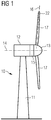
- a wind turbine 10 is shown.
- the wind turbine 10 comprises a nacelle 12 and a tower 11.
- the nacelle 12 is mounted at the top of the tower 11.
- the nacelle 12 is mounted rotatable with regard to the tower 11 by means of a yaw bearing.
- the axis of rotation of the nacelle 12 with regard to the tower 11 is referred to as the yaw axis.
- the wind turbine 10 also comprises a hub 13 with three rotor blades 17 (of which two rotor blades 17 are depicted in Figure 1 ).
- the hub 13 is mounted rotatable with regard to the nacelle 12 by means of a main bearing.
- the hub 13 is mounted rotatable about a rotor axis of rotation 14.
- the wind turbine 10 furthermore comprises a main shaft, which connects the hub 13 with a rotor of a generator 15.
- the hub 13 is connected directly to the rotor, thus the wind turbine 10 is referred to as a gearless, direct driven wind turbine.
- the hub 13 may also be connected to the rotor via a gearbox. This type of wind turbine is referred to as a geared wind turbine.
- the generator 15 is accommodated within the nacelle 12. It comprises the rotor and a stator. The generator 15 is arranged and prepared for converting the rotational energy from the rotor into electrical energy.
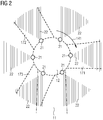
- FIG. 2 shows a schematic drawing of a wind turbine as viewed from the front and into the direction of the rotor axis of rotation.
- the nacelle 12 is illustrated as having a circular cross section and being positioned in the middle of Figure 2 .
- the tower 11 is illustrated having two dash-dotted lines as limitations.
- Three rotor blades are attached to the hub (not shown explicitly) of the wind turbine, namely a first rotor blade 171, a second rotor blade 172 and a third rotor blade 173.
- six noise detection devices 21 are connected to the nacelle 12.
- the noise detection devices 21 are evenly distributed along the circumferential line of the nacelle 12 in the cross sectional view.
- Each noise detection device 21 has a specific acoustic capture range 22.
- the acoustic capture range 22 denotes the range where a noise signal can be captured reliably.
- the noise detection devices 21 are mounted at the nacelle 12 that is stationary, the noise detection devices 21 can efficiently monitor the rotor blades 17 which are mounted on the rotating hub.
- the direction of rotation of the rotor is also illustrated 141 in Figure 2 .
- the rotor blades 17 are monitored by the set of noise detection devices 21.
- determination of the angular distribution of noise may be made by triangulation of two neighboring noise detection devices 21. Alternatively, it may also accurately be determined by one single noise detection device 21.
- Figure 3 shows the same wind turbine as in Figure 2 . More specifically, a controller 23 for choosing operational parameters based on the analysis of the measured noise is illustrated.
- the controller 23 is placed separately from the noise detection devices 21 and is connected to each of the noise detection devices 21 by noise detection connection means 24.
- These noise detection connection means 24 may be electric cables or optical fibers or wireless communications or other suitable means to connect the noise detection devices 21 that are installed at the nacelle of the wind turbine with the controller 23.
- the controller 23 is also installed at the nacelle of the wind turbine.
- the operational parameter that is chosen and set by the controller 23 is the variation of the pitch angle of the rotor blades 17.
- the rotor blades may be pitched, jointly or individually, about a pitch axis which is substantially coinciding with the longitudinal axes of the rotor blades 17.
- the direction of rotation of pitch 161 is shown for each of the three rotor blades 17.
- the noise measurements which are made by each noise detection device 21 are sent or transmitted to the central controller 23 which analyses the noise patterns and provides reactive measures if necessary. If for example, a local anomaly of noise is detected at a specific rotor blade 17, this information is fed forward to an individual rotor blades pitch system such that the lagging or trailing rotor blade, which is referred to as the rotor blade that follows the leading rotor blade, is countering the local anomaly with an already optimized and adapted pitch angle.
- Figure 4 shows such a case wherein a rotor blade 17 which is connected to a hub 13 experiences a wind anomaly.
- This translates into an airflow 26 which impinges on the rotor blade 17 with a specific orientation and intensity. Particularly at the tip section of the rotor blade 17, this creates, i.e. generates noise 27.
- This noise with an unusual and uncommon noise pattern and/or noise intensity is measured and captured by the noise detection device 21. It is captured as soon as it enters the capture range 22 of the noise detection device 21. Assuming the fact that the wind anomaly persists for a few seconds, e.g.
- the controller is able to send an appropriate signal to the rotor blade pitch system such that the trailing rotor blade 17 which is shown in Figure 5 is pitched about a certain pitch angle.
- This adapted pitch angle prevents or at least mitigates the generated noise.
- a feed-forward control mechanism is established based on noise measurements and controlled by a central controller.
- Figure 6 shows how a complete wind field can be generated and recorded if, for example, a set of noise detection devices is mounted to the nacelle of a wind turbine 10.
- the illustration in Figure 6 shows a first situation where a first noise distribution field 31 is detected.
- the height of the illustrated noise intensity or signal strength in Figure 6 describes the level of intensity of the noise which is referred to as the angular noise intensity 33.
- the first noise distribution field 31 represents a local "hot spot" in which the noise detection devices detected anomalously high acoustic emission.
- an appropriate reaction of the controller would be the sending of this feedback to the trailing rotor blades pitch system such that the trailing rotor blade can be pitched to a larger angle of attack. Consequently, less noise will be produced compared to the situation that no previous adaptation of the trailing rotor blade would have been performed.
- the rotor blade that detects the local hot spot is represented by the first rotor blade 171. Trailing rotor blades are the second rotor blade 172 and the third rotor blade 173.
- Figure 6 also shows a second scenario, wherein a second noise distribution field 32 is detected.
- a noise pattern is shown which does not indicate a local anomaly of the wind but rather a misalignment of the yawing direction between the incoming wind flow and the turbine. This could be due to a high wind shear and veer event.
- An advantageous reaction of the controller in this case would be the yawing of the complete nacelle including the hub with the rotor blades which are attached to or connected to the nacelle such that an overall reduction of the generated noise or generated acoustic emission can be realized.
Landscapes
- Engineering & Computer Science (AREA)
- Life Sciences & Earth Sciences (AREA)
- Sustainable Development (AREA)
- Sustainable Energy (AREA)
- Chemical & Material Sciences (AREA)
- Combustion & Propulsion (AREA)
- Mechanical Engineering (AREA)
- General Engineering & Computer Science (AREA)
- Physics & Mathematics (AREA)
- Fluid Mechanics (AREA)
- Wind Motors (AREA)
Claims (15)
- Procédé de contrôle d'une éolienne (10), l'éolienne (10) comprenant une tour (11), une nacelle (12), un moyeu rotatif (13), une première pale de rotor (171) et au moins une seconde pale de rotor (172), dans lequel les deux pales de rotor (171, 172) sont montées sur le moyeu (13), et
dans lequel le procédé comprend les étapes de- mesure du bruit (27) au moyen d'au moins un dispositif de détection de bruit (21), le bruit (27) étant généré dans au moins une section angulaire à l'intérieur du plan de rotor en raison d'une interaction entre la première pale de rotor (171) de l'éolienne (10) et un flux d'air (26) incident sur la première pale de rotor (171), et- modification de l'orientation de la seconde pale de rotor (172) par rapport à la direction du flux d'air incident (26) de sorte que le bruit qui est généré par l'interaction entre la seconde pale de rotor (172) et le flux d'air (26) incident sur la seconde pale de rotor (172) dans la section angulaire est modifié. - Procédé selon la revendication 1,
dans lequel le procédé comprend en outre les étapes de- détermination de la vitesse de rotation du rotor (18), et- calcul du temps prévu requis par la seconde pale de rotor (202) pour atteindre la section angulaire à l'intérieur du plan de rotor, dans lequel le calcul est réalisé sur la base de la vitesse de rotation déterminée du rotor (18) et de l'angle entre la première pale de rotor (201) et la seconde pale de rotor (202). - Procédé selon l'une des revendications précédentes, dans lequel- l'éolienne (10) comprend un ensemble de dispositifs de détection de bruit (21) pour mesurer le bruit (27), et- par la mesure simultanée du bruit par l'ensemble de dispositifs de détection de bruit (21), une image plus complète du bruit généré à l'intérieur du plan de rotor est obtenue.
- Procédé selon la revendication 3,
dans lequel une distribution angulaire du bruit (27) est déterminée par la triangulation de deux dispositifs de détection de bruit adjacents de l'ensemble de dispositifs de détection de bruit (21). - Procédé selon l'une des revendications précédentes, dans lequel le dispositif de détection de bruit (21) est monté de manière mobile par rapport à la première pale de rotor (171).
- Procédé selon la revendication 5,
dans lequel le dispositif de détection de bruit (21) est monté sur la nacelle (12) de l'éolienne (10), sur la tour (11) de l'éolienne (10) ou au sol où l'éolienne (10) est installée. - Procédé selon l'une des revendications 1 à 4,
dans lequel le dispositif de détection de bruit (21) est monté de manière stationnaire par rapport à la première pale de rotor (171). - Procédé selon la revendication 7,
dans lequel le dispositif de détection de bruit (21) est monté sur la première pale de rotor (171), sur la seconde pale de rotor (172) ou sur le moyeu (13) de l'éolienne (10). - Procédé selon l'une des revendications précédentes,
dans lequel l'orientation de la seconde pale de rotor (172) par rapport à la direction du flux d'air incident (26) est modifiée par un mouvement de tangage de la seconde pale de rotor (172). - Procédé selon l'une des revendications précédentes,
dans lequel l'orientation de la seconde pale de rotor (172) par rapport à la direction du flux d'air incident (26) est modifiée par un mouvement de lacet de la nacelle (12) de l'éolienne (10). - Procédé selon l'une des revendications précédentes,
dans lequel si le bruit qui a été généré dans la section angulaire à l'intérieur du plan de rotor par l'interaction entre les premières pales de rotor (172) et le flux d'air (26) incident sur la première pale de rotor (172) est supérieur à une valeur seuil de bruit prédéterminée, l'orientation de la seconde pale de rotor (172) par rapport à la direction du flux d'air incident (26) est modifiée de sorte que le bruit qui est généré dans la section angulaire par l'interaction entre les secondes pales de rotor (172) et le flux d'air (26) incident sur la seconde pale de rotor (172) est réduit comparativement au bruit qui a été généré dans la section angulaire par l'interaction entre la première pale de rotor (172) et le flux d'air (26) incident sur la première pale de rotor (172). - Procédé selon l'une des revendications précédentes,
dans lequel si le bruit qui a été généré dans la section angulaire à l'intérieur du plan de rotor par l'interaction entre les premières pales de rotor (172) et le flux d'air (26) incident sur la première pale de rotor (172) est inférieur à une valeur seuil de bruit prédéterminée, l'orientation de la seconde pale de rotor (172) par rapport à la direction du flux d'air incident (26) est modifiée de sorte que le bruit qui est généré dans la section angulaire par l'interaction entre les secondes pales de rotor (172) et le flux d'air (26) incident sur la seconde pale de rotor (172) est augmenté comparativement au bruit qui a été généré dans la section angulaire par l'interaction entre la première pale de rotor (172) et le flux d'air (26) incident sur la première pale de rotor (172). - Procédé selon l'une des revendications précédentes,
dans lequel le bruit mesuré est calculé en termes de vitesses du vent de sorte qu'un champ de vent pour la zone balayée des pales de rotor (171, 172) peut être obtenu. - Éolienne (10),
dans laquelle l'éolienne (10) comprend- une tour (11), une nacelle (12), un moyeu rotatif (13), une première pale de rotor (171) et au moins une seconde pale de rotor (172), dans laquelle les deux pales de rotor (171, 172) sont montées sur le moyeu (13),- au moins un dispositif de détection de bruit (21) pour mesurer le bruit (27) qui est généré dans une section angulaire à l'intérieur du plan de rotor en raison d'une interaction entre la première pale de rotor (171) de l'éolienne (10) et le flux d'air (26) incident sur la première pale de rotor (171),- des moyens pour modifier l'orientation de la seconde pale de rotor (172) par rapport à la direction du flux d'air incident (26) de sorte que le bruit qui est généré par l'interaction entre la seconde pale de rotor (172) et le flux d'air (26) incident sur la seconde pale de rotor (172) est modifié, et caractérisée en ce que l'éolienne comprend en outre- un contrôleur (23) pour analyser les données qui sont reçues à partir du dispositif de détection de bruit (21), analyser le bruit mesuré et choisir des instructions opérationnelles appropriées, dans laquelle le choix de paramètres opérationnels se rapporte au tangage individuel de la seconde pale de rotor (172). - Éolienne (10) selon la revendication 14,
dans laquelle le dispositif de détection de bruit (21) est un microphone.
Priority Applications (3)
| Application Number | Priority Date | Filing Date | Title |
|---|---|---|---|
| ES15161247T ES2763074T3 (es) | 2015-03-27 | 2015-03-27 | Control para una turbina eólica |
| EP15161247.0A EP3073108B1 (fr) | 2015-03-27 | 2015-03-27 | Controle d'une éolienne |
| DK15161247.0T DK3073108T3 (da) | 2015-03-27 | 2015-03-27 | Styring til en vindmølle |
Applications Claiming Priority (1)
| Application Number | Priority Date | Filing Date | Title |
|---|---|---|---|
| EP15161247.0A EP3073108B1 (fr) | 2015-03-27 | 2015-03-27 | Controle d'une éolienne |
Publications (2)
| Publication Number | Publication Date |
|---|---|
| EP3073108A1 EP3073108A1 (fr) | 2016-09-28 |
| EP3073108B1 true EP3073108B1 (fr) | 2019-10-02 |
Family
ID=52736987
Family Applications (1)
| Application Number | Title | Priority Date | Filing Date |
|---|---|---|---|
| EP15161247.0A Active EP3073108B1 (fr) | 2015-03-27 | 2015-03-27 | Controle d'une éolienne |
Country Status (3)
| Country | Link |
|---|---|
| EP (1) | EP3073108B1 (fr) |
| DK (1) | DK3073108T3 (fr) |
| ES (1) | ES2763074T3 (fr) |
Families Citing this family (5)
| Publication number | Priority date | Publication date | Assignee | Title |
|---|---|---|---|---|
| US10451039B2 (en) * | 2017-06-09 | 2019-10-22 | General Electric Company | System and method for reducing wind turbine noise during high wind speed conditions |
| CN110500233B (zh) * | 2018-05-18 | 2020-07-07 | 北京金风科创风电设备有限公司 | 用于多个风力发电机组的噪声控制的方法和装置 |
| CN110500234B (zh) | 2018-05-18 | 2020-07-03 | 北京金风科创风电设备有限公司 | 用于风力发电机组的噪声控制的方法和装置 |
| CN113153650A (zh) * | 2021-03-12 | 2021-07-23 | 中国大唐集团新能源科学技术研究院有限公司 | 一种风电机组的故障监测装置及其使用方法 |
| CN115306754B (zh) * | 2022-10-12 | 2023-02-17 | 中国航发四川燃气涡轮研究院 | 基于声阵列的轴流风扇气动失稳辨识方法 |
Family Cites Families (4)
| Publication number | Priority date | Publication date | Assignee | Title |
|---|---|---|---|---|
| JP2004293527A (ja) * | 2003-03-28 | 2004-10-21 | Ebara Corp | 風車装置、および風力発電装置 |
| US8277185B2 (en) | 2007-12-28 | 2012-10-02 | General Electric Company | Wind turbine, wind turbine controller and method for controlling a wind turbine |
| US7896613B2 (en) * | 2009-06-03 | 2011-03-01 | General Electric Company | System and method for wind turbine noise control and damage detection |
| US9528493B2 (en) | 2013-05-28 | 2016-12-27 | Siemens Aktiengesellschaft | Apparatus to detect aerodynamic conditions of blades of wind turbines |
-
2015
- 2015-03-27 DK DK15161247.0T patent/DK3073108T3/da active
- 2015-03-27 ES ES15161247T patent/ES2763074T3/es active Active
- 2015-03-27 EP EP15161247.0A patent/EP3073108B1/fr active Active
Non-Patent Citations (1)
| Title |
|---|
| None * |
Also Published As
| Publication number | Publication date |
|---|---|
| DK3073108T3 (da) | 2020-01-06 |
| ES2763074T3 (es) | 2020-05-27 |
| EP3073108A1 (fr) | 2016-09-28 |
Similar Documents
| Publication | Publication Date | Title |
|---|---|---|
| EP3073108B1 (fr) | Controle d'une éolienne | |
| CA2840441C (fr) | Procede et appareil de reduction du bruit des eoliennes | |
| US7638894B2 (en) | Method for operation of a wind energy installation | |
| EP2582975B1 (fr) | Commande d'éoliennes dans un parc d'éoliennes | |
| CN102859184B (zh) | 用于风力涡轮机的监测方法 | |
| JP5022102B2 (ja) | 風力発電装置、風力発電システムおよび風力発電装置の発電制御方法 | |
| EP2153062B1 (fr) | Procédé pour faire fonctionner une éolienne, éolienne et utilisation du procédé | |
| US8035241B2 (en) | Wind turbine, control system, and method for optimizing wind turbine power production | |
| US8334610B2 (en) | Gearless pitch control mechanism for starting, stopping and regulating the power output of wind turbines without the use of a brake | |
| EP2116721B1 (fr) | Éolienne avec commande de pas sans fil | |
| CA2778551C (fr) | Eolienne et methode de controle d'orientation connexe | |
| EP3067557B1 (fr) | Commande de point fixe de turbine éolienne | |
| GB2476506A (en) | Method And Apparatus Protecting Wind Turbines From Low Cycle Fatigue Damage | |
| US20180283352A1 (en) | Method for Preventing Wind Turbine Rotor Blade Tower Strikes | |
| WO2010061255A2 (fr) | Commande de pas active pour réduire le bruit ou les charges d'une éolienne | |
| CA2923290C (fr) | Commande d'eolienne au moyen d'un controleur de signal | |
| EP3124789B1 (fr) | Commande de turbine éolienne à l'aide d'un organe de commande secondaire pour régler la vitesse du vent et/ou des valeurs d'entrée de direction | |
| EP4170966A1 (fr) | Systèmes et procédés de commande d'un actif industriel en présence d'une cyberattaque | |
| EP3931439A1 (fr) | Dispositif de commande pour une turbine éolienne |
Legal Events
| Date | Code | Title | Description |
|---|---|---|---|
| PUAI | Public reference made under article 153(3) epc to a published international application that has entered the european phase |
Free format text: ORIGINAL CODE: 0009012 |
|
| AK | Designated contracting states |
Kind code of ref document: A1 Designated state(s): AL AT BE BG CH CY CZ DE DK EE ES FI FR GB GR HR HU IE IS IT LI LT LU LV MC MK MT NL NO PL PT RO RS SE SI SK SM TR |
|
| AX | Request for extension of the european patent |
Extension state: BA ME |
|
| STAA | Information on the status of an ep patent application or granted ep patent |
Free format text: STATUS: REQUEST FOR EXAMINATION WAS MADE |
|
| 17P | Request for examination filed |
Effective date: 20170328 |
|
| RBV | Designated contracting states (corrected) |
Designated state(s): AL AT BE BG CH CY CZ DE DK EE ES FI FR GB GR HR HU IE IS IT LI LT LU LV MC MK MT NL NO PL PT RO RS SE SI SK SM TR |
|
| RAP1 | Party data changed (applicant data changed or rights of an application transferred) |
Owner name: SIEMENS AKTIENGESELLSCHAFT |
|
| GRAP | Despatch of communication of intention to grant a patent |
Free format text: ORIGINAL CODE: EPIDOSNIGR1 |
|
| STAA | Information on the status of an ep patent application or granted ep patent |
Free format text: STATUS: GRANT OF PATENT IS INTENDED |
|
| RAP1 | Party data changed (applicant data changed or rights of an application transferred) |
Owner name: SIEMENS GAMESA RENEWABLE ENERGY A/S |
|
| INTG | Intention to grant announced |
Effective date: 20190425 |
|
| GRAS | Grant fee paid |
Free format text: ORIGINAL CODE: EPIDOSNIGR3 |
|
| GRAA | (expected) grant |
Free format text: ORIGINAL CODE: 0009210 |
|
| STAA | Information on the status of an ep patent application or granted ep patent |
Free format text: STATUS: THE PATENT HAS BEEN GRANTED |
|
| AK | Designated contracting states |
Kind code of ref document: B1 Designated state(s): AL AT BE BG CH CY CZ DE DK EE ES FI FR GB GR HR HU IE IS IT LI LT LU LV MC MK MT NL NO PL PT RO RS SE SI SK SM TR |
|
| REG | Reference to a national code |
Ref country code: GB Ref legal event code: FG4D |
|
| REG | Reference to a national code |
Ref country code: CH Ref legal event code: EP Ref country code: AT Ref legal event code: REF Ref document number: 1186451 Country of ref document: AT Kind code of ref document: T Effective date: 20191015 |
|
| REG | Reference to a national code |
Ref country code: DE Ref legal event code: R096 Ref document number: 602015038925 Country of ref document: DE |
|
| REG | Reference to a national code |
Ref country code: IE Ref legal event code: FG4D |
|
| REG | Reference to a national code |
Ref country code: DK Ref legal event code: T3 Effective date: 20191218 |
|
| REG | Reference to a national code |
Ref country code: NL Ref legal event code: MP Effective date: 20191002 |
|
| REG | Reference to a national code |
Ref country code: LT Ref legal event code: MG4D |
|
| REG | Reference to a national code |
Ref country code: AT Ref legal event code: MK05 Ref document number: 1186451 Country of ref document: AT Kind code of ref document: T Effective date: 20191002 |
|
| PG25 | Lapsed in a contracting state [announced via postgrant information from national office to epo] |
Ref country code: PT Free format text: LAPSE BECAUSE OF FAILURE TO SUBMIT A TRANSLATION OF THE DESCRIPTION OR TO PAY THE FEE WITHIN THE PRESCRIBED TIME-LIMIT Effective date: 20200203 Ref country code: FI Free format text: LAPSE BECAUSE OF FAILURE TO SUBMIT A TRANSLATION OF THE DESCRIPTION OR TO PAY THE FEE WITHIN THE PRESCRIBED TIME-LIMIT Effective date: 20191002 Ref country code: BG Free format text: LAPSE BECAUSE OF FAILURE TO SUBMIT A TRANSLATION OF THE DESCRIPTION OR TO PAY THE FEE WITHIN THE PRESCRIBED TIME-LIMIT Effective date: 20200102 Ref country code: GR Free format text: LAPSE BECAUSE OF FAILURE TO SUBMIT A TRANSLATION OF THE DESCRIPTION OR TO PAY THE FEE WITHIN THE PRESCRIBED TIME-LIMIT Effective date: 20200103 Ref country code: PL Free format text: LAPSE BECAUSE OF FAILURE TO SUBMIT A TRANSLATION OF THE DESCRIPTION OR TO PAY THE FEE WITHIN THE PRESCRIBED TIME-LIMIT Effective date: 20191002 Ref country code: NO Free format text: LAPSE BECAUSE OF FAILURE TO SUBMIT A TRANSLATION OF THE DESCRIPTION OR TO PAY THE FEE WITHIN THE PRESCRIBED TIME-LIMIT Effective date: 20200102 Ref country code: SE Free format text: LAPSE BECAUSE OF FAILURE TO SUBMIT A TRANSLATION OF THE DESCRIPTION OR TO PAY THE FEE WITHIN THE PRESCRIBED TIME-LIMIT Effective date: 20191002 Ref country code: LV Free format text: LAPSE BECAUSE OF FAILURE TO SUBMIT A TRANSLATION OF THE DESCRIPTION OR TO PAY THE FEE WITHIN THE PRESCRIBED TIME-LIMIT Effective date: 20191002 Ref country code: AT Free format text: LAPSE BECAUSE OF FAILURE TO SUBMIT A TRANSLATION OF THE DESCRIPTION OR TO PAY THE FEE WITHIN THE PRESCRIBED TIME-LIMIT Effective date: 20191002 Ref country code: LT Free format text: LAPSE BECAUSE OF FAILURE TO SUBMIT A TRANSLATION OF THE DESCRIPTION OR TO PAY THE FEE WITHIN THE PRESCRIBED TIME-LIMIT Effective date: 20191002 Ref country code: NL Free format text: LAPSE BECAUSE OF FAILURE TO SUBMIT A TRANSLATION OF THE DESCRIPTION OR TO PAY THE FEE WITHIN THE PRESCRIBED TIME-LIMIT Effective date: 20191002 |
|
| REG | Reference to a national code |
Ref country code: ES Ref legal event code: FG2A Ref document number: 2763074 Country of ref document: ES Kind code of ref document: T3 Effective date: 20200527 |
|
| PG25 | Lapsed in a contracting state [announced via postgrant information from national office to epo] |
Ref country code: CZ Free format text: LAPSE BECAUSE OF FAILURE TO SUBMIT A TRANSLATION OF THE DESCRIPTION OR TO PAY THE FEE WITHIN THE PRESCRIBED TIME-LIMIT Effective date: 20191002 Ref country code: IS Free format text: LAPSE BECAUSE OF FAILURE TO SUBMIT A TRANSLATION OF THE DESCRIPTION OR TO PAY THE FEE WITHIN THE PRESCRIBED TIME-LIMIT Effective date: 20200224 Ref country code: RS Free format text: LAPSE BECAUSE OF FAILURE TO SUBMIT A TRANSLATION OF THE DESCRIPTION OR TO PAY THE FEE WITHIN THE PRESCRIBED TIME-LIMIT Effective date: 20191002 Ref country code: HR Free format text: LAPSE BECAUSE OF FAILURE TO SUBMIT A TRANSLATION OF THE DESCRIPTION OR TO PAY THE FEE WITHIN THE PRESCRIBED TIME-LIMIT Effective date: 20191002 |
|
| PG25 | Lapsed in a contracting state [announced via postgrant information from national office to epo] |
Ref country code: AL Free format text: LAPSE BECAUSE OF FAILURE TO SUBMIT A TRANSLATION OF THE DESCRIPTION OR TO PAY THE FEE WITHIN THE PRESCRIBED TIME-LIMIT Effective date: 20191002 |
|
| REG | Reference to a national code |
Ref country code: DE Ref legal event code: R097 Ref document number: 602015038925 Country of ref document: DE |
|
| PG2D | Information on lapse in contracting state deleted |
Ref country code: IS |
|
| PG25 | Lapsed in a contracting state [announced via postgrant information from national office to epo] |
Ref country code: EE Free format text: LAPSE BECAUSE OF FAILURE TO SUBMIT A TRANSLATION OF THE DESCRIPTION OR TO PAY THE FEE WITHIN THE PRESCRIBED TIME-LIMIT Effective date: 20191002 Ref country code: RO Free format text: LAPSE BECAUSE OF FAILURE TO SUBMIT A TRANSLATION OF THE DESCRIPTION OR TO PAY THE FEE WITHIN THE PRESCRIBED TIME-LIMIT Effective date: 20191002 Ref country code: IS Free format text: LAPSE BECAUSE OF FAILURE TO SUBMIT A TRANSLATION OF THE DESCRIPTION OR TO PAY THE FEE WITHIN THE PRESCRIBED TIME-LIMIT Effective date: 20200202 |
|
| PLBE | No opposition filed within time limit |
Free format text: ORIGINAL CODE: 0009261 |
|
| STAA | Information on the status of an ep patent application or granted ep patent |
Free format text: STATUS: NO OPPOSITION FILED WITHIN TIME LIMIT |
|
| PG25 | Lapsed in a contracting state [announced via postgrant information from national office to epo] |
Ref country code: SM Free format text: LAPSE BECAUSE OF FAILURE TO SUBMIT A TRANSLATION OF THE DESCRIPTION OR TO PAY THE FEE WITHIN THE PRESCRIBED TIME-LIMIT Effective date: 20191002 Ref country code: IT Free format text: LAPSE BECAUSE OF FAILURE TO SUBMIT A TRANSLATION OF THE DESCRIPTION OR TO PAY THE FEE WITHIN THE PRESCRIBED TIME-LIMIT Effective date: 20191002 Ref country code: SK Free format text: LAPSE BECAUSE OF FAILURE TO SUBMIT A TRANSLATION OF THE DESCRIPTION OR TO PAY THE FEE WITHIN THE PRESCRIBED TIME-LIMIT Effective date: 20191002 |
|
| 26N | No opposition filed |
Effective date: 20200703 |
|
| PG25 | Lapsed in a contracting state [announced via postgrant information from national office to epo] |
Ref country code: MC Free format text: LAPSE BECAUSE OF FAILURE TO SUBMIT A TRANSLATION OF THE DESCRIPTION OR TO PAY THE FEE WITHIN THE PRESCRIBED TIME-LIMIT Effective date: 20191002 |
|
| REG | Reference to a national code |
Ref country code: CH Ref legal event code: PL |
|
| PG25 | Lapsed in a contracting state [announced via postgrant information from national office to epo] |
Ref country code: SI Free format text: LAPSE BECAUSE OF FAILURE TO SUBMIT A TRANSLATION OF THE DESCRIPTION OR TO PAY THE FEE WITHIN THE PRESCRIBED TIME-LIMIT Effective date: 20191002 |
|
| REG | Reference to a national code |
Ref country code: BE Ref legal event code: MM Effective date: 20200331 |
|
| PG25 | Lapsed in a contracting state [announced via postgrant information from national office to epo] |
Ref country code: LU Free format text: LAPSE BECAUSE OF NON-PAYMENT OF DUE FEES Effective date: 20200327 |
|
| PG25 | Lapsed in a contracting state [announced via postgrant information from national office to epo] |
Ref country code: IE Free format text: LAPSE BECAUSE OF NON-PAYMENT OF DUE FEES Effective date: 20200327 Ref country code: CH Free format text: LAPSE BECAUSE OF NON-PAYMENT OF DUE FEES Effective date: 20200331 Ref country code: LI Free format text: LAPSE BECAUSE OF NON-PAYMENT OF DUE FEES Effective date: 20200331 |
|
| PG25 | Lapsed in a contracting state [announced via postgrant information from national office to epo] |
Ref country code: BE Free format text: LAPSE BECAUSE OF NON-PAYMENT OF DUE FEES Effective date: 20200331 |
|
| PGFP | Annual fee paid to national office [announced via postgrant information from national office to epo] |
Ref country code: GB Payment date: 20220324 Year of fee payment: 8 Ref country code: DK Payment date: 20220322 Year of fee payment: 8 Ref country code: DE Payment date: 20220322 Year of fee payment: 8 |
|
| PG25 | Lapsed in a contracting state [announced via postgrant information from national office to epo] |
Ref country code: TR Free format text: LAPSE BECAUSE OF FAILURE TO SUBMIT A TRANSLATION OF THE DESCRIPTION OR TO PAY THE FEE WITHIN THE PRESCRIBED TIME-LIMIT Effective date: 20191002 Ref country code: MT Free format text: LAPSE BECAUSE OF FAILURE TO SUBMIT A TRANSLATION OF THE DESCRIPTION OR TO PAY THE FEE WITHIN THE PRESCRIBED TIME-LIMIT Effective date: 20191002 Ref country code: CY Free format text: LAPSE BECAUSE OF FAILURE TO SUBMIT A TRANSLATION OF THE DESCRIPTION OR TO PAY THE FEE WITHIN THE PRESCRIBED TIME-LIMIT Effective date: 20191002 |
|
| PGFP | Annual fee paid to national office [announced via postgrant information from national office to epo] |
Ref country code: FR Payment date: 20220323 Year of fee payment: 8 |
|
| PG25 | Lapsed in a contracting state [announced via postgrant information from national office to epo] |
Ref country code: MK Free format text: LAPSE BECAUSE OF FAILURE TO SUBMIT A TRANSLATION OF THE DESCRIPTION OR TO PAY THE FEE WITHIN THE PRESCRIBED TIME-LIMIT Effective date: 20191002 |
|
| PGFP | Annual fee paid to national office [announced via postgrant information from national office to epo] |
Ref country code: ES Payment date: 20220420 Year of fee payment: 8 |
|
| REG | Reference to a national code |
Ref country code: DE Ref legal event code: R082 Ref document number: 602015038925 Country of ref document: DE Representative=s name: SAUTHOFF, KARSTEN, DIPL.-ING. UNIV., DE |
|
| REG | Reference to a national code |
Ref country code: DE Ref legal event code: R119 Ref document number: 602015038925 Country of ref document: DE |
|
| REG | Reference to a national code |
Ref country code: DK Ref legal event code: EBP Effective date: 20230331 |
|
| GBPC | Gb: european patent ceased through non-payment of renewal fee |
Effective date: 20230327 |
|
| PG25 | Lapsed in a contracting state [announced via postgrant information from national office to epo] |
Ref country code: GB Free format text: LAPSE BECAUSE OF NON-PAYMENT OF DUE FEES Effective date: 20230327 |
|
| PG25 | Lapsed in a contracting state [announced via postgrant information from national office to epo] |
Ref country code: GB Free format text: LAPSE BECAUSE OF NON-PAYMENT OF DUE FEES Effective date: 20230327 Ref country code: FR Free format text: LAPSE BECAUSE OF NON-PAYMENT OF DUE FEES Effective date: 20230331 Ref country code: DE Free format text: LAPSE BECAUSE OF NON-PAYMENT OF DUE FEES Effective date: 20231003 |
|
| PG25 | Lapsed in a contracting state [announced via postgrant information from national office to epo] |
Ref country code: DK Free format text: LAPSE BECAUSE OF NON-PAYMENT OF DUE FEES Effective date: 20230331 |