EP3072814B1 - Heckrotorblattanordung eines drehflueglers und ihr herstellungsverfahren - Google Patents
Heckrotorblattanordung eines drehflueglers und ihr herstellungsverfahren Download PDFInfo
- Publication number
- EP3072814B1 EP3072814B1 EP15188195.0A EP15188195A EP3072814B1 EP 3072814 B1 EP3072814 B1 EP 3072814B1 EP 15188195 A EP15188195 A EP 15188195A EP 3072814 B1 EP3072814 B1 EP 3072814B1
- Authority
- EP
- European Patent Office
- Prior art keywords
- rotor blade
- fitting
- inboard
- rotor
- assembly
- Prior art date
- Legal status (The legal status is an assumption and is not a legal conclusion. Google has not performed a legal analysis and makes no representation as to the accuracy of the status listed.)
- Active
Links
- 238000000034 method Methods 0.000 title claims description 14
- 239000002131 composite material Substances 0.000 claims description 68
- 230000033001 locomotion Effects 0.000 description 7
- 230000005540 biological transmission Effects 0.000 description 5
- 230000000712 assembly Effects 0.000 description 3
- 238000000429 assembly Methods 0.000 description 3
- 230000008569 process Effects 0.000 description 3
- 230000008901 benefit Effects 0.000 description 2
- 125000004122 cyclic group Chemical group 0.000 description 2
- 230000000694 effects Effects 0.000 description 2
- 238000004519 manufacturing process Methods 0.000 description 2
- 239000000463 material Substances 0.000 description 2
- 230000007704 transition Effects 0.000 description 2
- 229920004934 Dacron® Polymers 0.000 description 1
- 229920005830 Polyurethane Foam Polymers 0.000 description 1
- 239000004809 Teflon Substances 0.000 description 1
- 229920006362 Teflon® Polymers 0.000 description 1
- 230000008859 change Effects 0.000 description 1
- 238000000576 coating method Methods 0.000 description 1
- 239000006260 foam Substances 0.000 description 1
- 238000009434 installation Methods 0.000 description 1
- 239000005020 polyethylene terephthalate Substances 0.000 description 1
- 239000011496 polyurethane foam Substances 0.000 description 1
- 229910001220 stainless steel Inorganic materials 0.000 description 1
- 239000010935 stainless steel Substances 0.000 description 1
Images


Classifications
-
- B—PERFORMING OPERATIONS; TRANSPORTING
- B64—AIRCRAFT; AVIATION; COSMONAUTICS
- B64C—AEROPLANES; HELICOPTERS
- B64C27/00—Rotorcraft; Rotors peculiar thereto
- B64C27/32—Rotors
- B64C27/46—Blades
-
- B—PERFORMING OPERATIONS; TRANSPORTING
- B64—AIRCRAFT; AVIATION; COSMONAUTICS
- B64C—AEROPLANES; HELICOPTERS
- B64C27/00—Rotorcraft; Rotors peculiar thereto
- B64C27/32—Rotors
- B64C27/46—Blades
- B64C27/473—Constructional features
- B64C27/48—Root attachment to rotor head
-
- B—PERFORMING OPERATIONS; TRANSPORTING
- B64—AIRCRAFT; AVIATION; COSMONAUTICS
- B64C—AEROPLANES; HELICOPTERS
- B64C27/00—Rotorcraft; Rotors peculiar thereto
- B64C27/32—Rotors
- B64C27/46—Blades
- B64C27/473—Constructional features
- B64C2027/4733—Rotor blades substantially made from particular materials
- B64C2027/4736—Rotor blades substantially made from particular materials from composite materials
Definitions
- This specification relates to rotor blades, e.g., tail rotor blades, of a rotorcraft, e.g., a helicopter.
- Helicopters often include a tail rotor assembly, which includes two or more blades rotated about a central axis of rotation to generate thrust.
- the thrust can be used to counter the torque effect created by a main rotor assembly and can also be used to allow a pilot to control the yaw of a helicopter.
- the amount and direction of the thrust is generally controlled by collectively changing the angles of attack of all of the tail rotor blades together.
- Tail rotor blades can also accommodate at least some amount of cyclic flapping and feathering to counter the dissymmetry of lift phenomenon that occurs as a helicopter moves through the air. For example, as a tail rotor blade moves in the same direction as the helicopter movement (e.g., an advancing blade in forward flight), the tail rotor blade experiences a greater air speed, generates more thrust, and flaps in the direction opposite to the thrust. In another example, as a tail rotor blade moves in the opposite direction as the helicopter movement (e.g., a retreating blade in forward flight), the tail rotor blade experiences a lower air speed, generates less thrust, and flaps in the direction of the thrust.
- a tail rotor blade moves in the same direction as the helicopter movement (e.g., an advancing blade in forward flight)
- the tail rotor blade experiences a greater air speed, generates more thrust, and flaps in the direction opposite to the thrust.
- the tail rotor blade experiences a lower air speed, generates less thrust, and flaps
- tail rotor blades can be designed to decrease the angle of attack of the blades as the blades move in the same direction as the helicopter movement and increase the angle of attack of the blades as they move in the opposite direction of the helicopter movement.
- the cyclic changing of the angles of attack is commonly referred to as feathering or delta-3 and is used to balance the thrust generated by each of the tail rotor blades and limit flapping angles.
- US4626172A discloses a plurality of blades fixed to a hub by the root part of a spar, arranged in the form of a loop surrounding a connection element bolted on the hub, with the interposition of rigid rings by a pin simultaneously fixing the hub on a drive sleeve transmitting thereto the driving torque of the central shaft.
- the hub comprises two coaxial cylindrical walls in each of which is pierced, for each blade, a circular opening in which the member for controlling the angle of attack which is fast with the blade root is mounted to rotate via self-lubricating rings.
- This disclosure relates to composite yoke fitting for bearing attachment to rotorcraft blade.
- the present invention provides a rotorcraft tail rotor blade assembly as defined by the features of claim 1 and a method of forming a rotorcraft tail rotor assembly as defined by the steps of claim 9.
- a rotor blade assembly includes a rotor blade comprising an inboard end and an outboard end.
- a composite yoke fitting made from a composite material is attached to the rotor blade.
- the composite yoke fitting includes an outboard portion inserted into the inboard end of the rotor blade, an inboard portion, and a flexure region about which the rotor blade is configured to flex. The inboard portion and the flexure region are outside the rotor blade.
- the inboard portion can be configured to attach to a rotor hub assembly configured to rotate the rotor blade.
- the inboard portion can include a cutout configured to attach to a bearing in the rotor hub assembly.
- the cutout can include a through hole formed in the inboard portion.
- the composite yoke fitting can taper from the inboard portion toward the outboard portion.
- the flexure region can be between the outboard portion and the inboard portion.
- the flexure region can have a thickness less than a thickness of the outboard portion and a thickness of the inboard portion.
- the rotor blade can include an upper skin portion and a lower skin portion.
- the outboard portion can be sandwiched and bonded between the upper skin portion and the lower skin portion.
- the composite yoke fitting can include an upper fitting portion and a lower fitting portion. A portion of the upper fitting portion and a portion of the lower fitting portion are inserted into the inboard end of the rotor blade.
- an outboard portion of a composite yoke fitting is inserted into an inboard end of a rotor blade.
- the composite yoke fitting includes an outboard portion and a flexure region about which the rotor blade is configured to flex.
- the inboard portion and the flexure region are outside the rotor blade.
- the composite yoke fitting is bonded to the rotor blade.
- the inboard portion can be attached to a rotor hub assembly configured to rotate the rotor blade.
- the inboard portion can include a cutout configured to attach to a bearing in the rotor hub assembly.
- the inboard portion can be attached to the rotor hub assembly through the cutout.
- the cutout can include a through hole formed in the outboard portion.
- the flexure region can be between the inboard portion and the outboard portion.
- the flexure region can have a thickness less than a thickness of the outboard portion and a thickness of the inboard portion.
- the rotor blade can include an upper skin portion and a lower skin portion.
- the outboard portion of the composite yoke fitting can be inserted between the upper skin portion and the lower skin portion.
- the composite yoke fitting can include an upper fitting portion and a lower fitting portion. A portion of the upper fitting portion and the lower fitting portion can be inserted between and bonded to a portion of the upper skin portion and a portion of the lower skin portion.
- a composite yoke fitting including an outboard portion, a flexure region, and an inboard portion is attached to a rotor blade.
- the outboard portion extends into the rotor blade.
- the flexure region is outside the rotor blade.
- the composite yoke fitting is bonded to the rotor blade.
- the rotor blade can include an upper skin portion and a lower skin portion.
- the outboard portion can be inserted between the upper skin portion and the lower skin portion.
- the upper skin portion and the lower skin portion can be bonded to the outboard portion.
- the composite yoke fitting can include an upper fitting portion and a lower fitting portion.
- a portion of the upper fitting portion and a portion of the lower fitting portion can be inserted into the rotor blade.
- the portion of the upper fitting portion and the portion of the lower fitting portion can be bonded to the rotor blade.
- the inboard portion can be attached to a rotor hub assembly configured to rotate the rotor blade through a cutout formed in the inboard portion.
- the cutout can be configured to attach to a bearing in the rotor hub assembly.
- Centrifugal force generated by a rotor blade can be transferred into the tail rotor hub in a variety of ways.
- two-bladed tail rotor hubs can utilize a metallic block in the root end of the blade bonded to the blade skins or a cuff section of an inboard end of the blade that is integral to the blade skins.
- a composite strap which is either bolted to the blade (e.g., roughly midspan) or bonded to the inner mold line (IML) surface of the blade, can be used.
- the composite strap can accommodate feathering/pitch change motion as well as centrifugal reaction.
- the inboard end of the blade can be used as an attachment flange for a metallic fitting that can interface with the tail rotor hub in a variety of configurations.
- a fully articulated hub can utilize a spherical elastomeric centrifugal bearing in conjunction with a gas lead/lag damper.
- the inboard end of the blade is often bolted to the metallic fitting that interfaces with the spherical elastomeric centrifugal bearing and the damper.
- a composite yoke fitting for bearing attachment to rotorcraft blade.
- a composite yoke fitting is integrated on an inboard end of a rotor blade, e.g., a tail rotor blade.
- the outboard end of the yoke fitting can be contoured and tapered to match the geometry of the blade skins. All components can be bonded together.
- the inboard end of the composite yoke fitting can include a cutout to facilitate attachment to the hub via a bearing, e.g., a spherical, elastomeric centrifugal bearing, which nests into the cutout in the composite yoke fitting.
- the rotor blade assembly described here can allow for the rotor blade to act as the primary load path for centrifugal force without the use of additional fittings, e.g., metallic fittings. Instead, the rotor blade assembly uses can integral composite yoke to transfer the centrifugal force from the rotor blade into the centrifugal force bearing.
- This style of blade can provide a low frontal cross-section which can provide manufacturing benefits when compared to tail rotor blades with open-style inbound ends.
- the rotor blade assembly can eliminate the use of additional fittings and/or bolted joints that are typically used to provide an interface between the root end of the blade and the bearing in the rotor blade assembly.
- the resulting rotor blade assembly can be lighter with a more durable interface with fewer parts relative to rotor blade assemblies that use fittings and/or bolted joints.
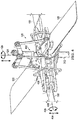
- FIG. 1 is a perspective view of a helicopter 100.
- Helicopter 100 includes a main rotor assembly 110, a tail rotor assembly 120, a fuselage 130, and landing gear 140.
- Main rotor assembly 110 includes two or more blades 112 that are rotated about an axis of rotation 114 in either a clockwise direction or a counterclockwise direction as indicated by arrow 116.
- Main rotor assembly generates a lift force that supports the weight of helicopter 100 and a thrust force that counteracts aerodynamic drag.
- Main rotor assembly 110 can also be used to induce pitch and roll of helicopter 100.
- Tail rotor assembly 120 includes two or more blades 122 that are rotated about an axis of rotation 124 in either a clockwise direction or a counterclockwise direction as indicated by arrow 126. Tail rotor assembly 120 counters the torque effect created by main rotor assembly 110 and allows a pilot to control the yaw of helicopter 100.
- Fuselage 130 is the main body section of helicopter 100. Fuselage 130 can hold the crew, passengers and/or cargo, and can house the engine, transmission, gear boxes, drive shafts, control systems, etc., that make the helicopter 100 operable.
- Landing gear 140 can be attached to fuselage 130 and can support the helicopter 100 on the ground, allowing the helicopter to take off and land.
- the composite yoke fitting described here can be implemented in either the blades 112 of the main rotor assembly 110 or the blades 122 of the tail rotor assembly 120.
- the composite yoke fitting can be implemented with blades in other types of aircrafts, e.g., tiltrotors.
- FIG. 2 is a perspective view of a power train 200.
- Power train 200 can be used in a rotor assembly of a helicopter such as helicopter 100 shown in FIG. 1 or in other rotor assemblies (e.g., fully articulated, rigid, semi-rigid, gimbaled, or other rotor assemblies) having any number of blades (e.g., 2, 3, 4, 5, 6, or other number of blades).
- Power train 200 can include a transmission 202 that receives power from an engine (not shown) through a driveshaft 204.
- Transmission 202 can drive accessories and control the rotation 116 of mast 206 about an axis of rotation 114.
- Mast 206 can transfer its rotational movement to blades 112 through a hub 208 that connects mast 206 to blades 112.
- Hub 208 can include one or more flexible yokes 210 that enable blades 112 to flap up and down in the directions indicated by arrows 212 and 214, respectively.
- the hub 208 can include a main rotor grip 216 for each blade 112 that is attached to hub 208.
- Main rotor grip 216 can include an outboard end that attaches to a blade 112, an inboard end that attaches to a pitch horn 218, and a spindle between the outboard end and the inboard end.
- the spindle can be supported by a shear bearing 220 that holds the spindle in place and allows it to rotate.
- the shear bearing 220 can, in turn, be held by a bridge plate 222 that attaches shear bearing 220 to yoke 210.
- Each pitch horn 218 can be connected to a pitch linkage 224.
- Each pitch linkage 224 can be drive up and down, e.g., in the directions of arrows 212 and 214, respectively, by a swashplate assembly 226.
- swashplate assembly 226 moves, it drives pitch linkage 224, which drives pitch horn 218 which rotates main rotor grip 216 about shear bearing 220, allowing the pitch of each of the blades 112 to be controlled.
- each blade 112 can rotate clockwise or counterclockwise about an axis of rotation 230 that runs along the length of each blade 112.
- Fig. 3 is a perspective view of a tail rotor drive assembly 300.
- Tail rotor drive assembly 300 can be used in a helicopter, e.g., the helicopter 100.
- the tail rotor drive assembly 300 can include a first driveshaft segment 302, a second driveshaft segment 304, an intermediate gearbox 306 and a tail rotor gearbox 308.
- the driveshaft segments 302, 304 and gearboxes 306, 308 can be housed in a tail boom 310 and a tail 314 that are components of a helicopter fuselage, e.g., fuselage 130.
- a first driveshaft segment 302 can be driven by a transmission (e.g., transmission 202) and can be connected to intermediate gearbox 306.
- the intermediate gearbox 306 can translate rotation from first driveshaft segment 302 to second driveshaft segment 304.
- the second driveshaft segment 304 can be connected to tail rotor gearbox 308 that translates rotation from second driveshaft segment 304 to tail rotor mast 312.
- tail rotor gearbox 308 can be used to rotate tail rotor mast 312 about an axis of rotation 124 that is at substantially a 90° angle with respect to second driveshaft segment 304.
- one or both of gearboxes 306 and 308 may increase or decrease the speed of rotation (e.g., increase or decrease the number of revolutions per minute) such that tail rotor blades 122 are rotated either clockwise or counterclockwise at an appropriate speed in the directions indicated by arrow 126.
- FIG. 4 is a perspective view of a tail rotor assembly 120 having a tail rotor hub 402.
- the tail rotor hub 402 can include a gimbal assembly that can attach tail rotor hub 402 to tail rotor mast 312.
- the gimbal assembly can translate rotational movement of tail rotor mast 312 to tail rotor hub 402 such that both tail rotor mast 312 and tail rotor hub 402 rotate about axis of rotation 124 in the directions indicated by arrow 126.
- the gimbal assembly can enable tail rotor hub 402 and the attached blades 122 to flap in the directions indicated by arrow 404.
- Each tail rotor blade 122 is supported by a CF bearing 430.
- Each CF bearing is configured to support a blade 122 and withstand centrifugal force that is generated as blade 122 is rotated about tail rotor mast 312.
- CF bearing 430 is also configured to accommodate blade 122 pitch changes (e.g., blade 122 rotation about axis 426 in the directions indicated by arrow 428).
- CF bearing 430 is an elastomeric bearing (e.g., a spherical elastomeric bearing). Spherical elastomeric bearings can be easier to maintain relative to other types of bearings (e.g., stainless steel bearings with Teflon/Dacron coatings).
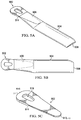
- FIGS. 5A-5E are example views of a composite yoke fitting attached to a rotor blade to form a rotor blade assembly.
- FIG. 5A and FIG. 5B are a perspective view and a top view, respectively, of the composite yoke fitting 502 attached to a rotor blade 504.
- FIG. 5C is a perspective view of the composite yoke fitting 502.
- the rotor blade 504 includes an inboard end 506 and an outboard end 508. The inboard end 506 is connected to the rotor assembly (not shown in FIGS. 5A-5C ).
- the composite yoke fitting 502 is made from a composite material.
- the composite material can include laminated tape or wound roving material formed into belts.
- the composite yoke fitting 502 includes an outboard portion 510 and an inboard portion 512.
- the outboard portion 510 is configured to be inserted into the inboard end 506 of the rotor blade 504.
- a length of the outboard portion 510 that is inserted into the inboard end 506 of the rotor blade 504 can have sufficient area to transfer centrifugal force load from the rotor blade skins to the composite yoke fitting 502.
- the composite yoke fitting 502 also includes a flexure region 514 about which the rotor blade 504 is configured to flex during operation. When the composite yoke fitting 502 is attached to the rotor blade 504, the inboard portion 510 and the flexure region 514 are outside the rotor blade 504.
- the inboard portion 512 of the composite yoke fitting 502 is configured to attach to a rotor hub assembly configured to rotate the rotor blade 504, e.g., the tail rotor assembly 120.
- composite yoke fitting 502 includes a cutout 516, e.g., in the inboard portion 510.
- the cutout 516 is configured to attach to a bearing in the rotor hub assembly.
- the cutout can include a through hole formed in the inboard portion 510 to accommodate the installation of the bearing, e.g., a spherical elastomeric bearing, which, among other functions, can transfer centrifugal force into the tail rotor assembly 120.
- the composite yoke fitting 502 can taper from the inboard portion 510 toward the outboard portion 512.
- a width of the composite yoke fitting 502 at an end of the inboard portion 510 can be greater than a width at an end of the inboard portion 512.
- the tapering width can give the composite yoke fitting 502 a substantially triangular appearance.
- the flexure region 514 is between the inboard portion 510 and the outboard portion 512.
- a thickness of the flexure region 514 can be less than a thickness of the outboard portion 512 and a thickness of the inboard portion 510.
- a thickness of the composite yoke fitting 502 can be substantially constant in the inboard portion 510, decrease as the composite yoke fitting 502 transitions from the inboard portion 510 to the flexure region 514, increase as the composite yoke fitting 502 transitions from the flexure region 514 to the outboard portion 512, and be substantially constant in the outboard portion 512.
- FIG. 6 is a flowchart of an example process 600 for attaching a composite yoke fitting to a rotor blade.
- the process 600 can be implemented, for example, in a shop floor while manufacturing a rotor blade assembly such as the rotor blade assembly described above with reference to FIGS. 5A-5E .
- an inboard portion of a composite yoke fitting is inserted into an inboard end of a rotor blade.
- the composite yoke fitting for example, the composite yoke fitting 502 can include an outboard portion and a flexure region about which the rotor blade is configured to flex. The inboard portion and the flexure region can be outside the rotor blade.
- the composite yoke fitting is attached to, for example, bonded to or otherwise adhered to, the rotor blade.
- the rotor blade for example, the rotor blade 504
- the rotor blade material 526 e.g., a foam core such as rohacell or molded polyurethane foam is positioned, as shown in FIG. 5D .
- the outboard portion 512 of the composite yoke fitting 502 can be sandwiched and bonded between the upper skin portion 522 and the lower skin portion 524.
- the composite yoke fitting 502 can include an upper fitting portion 532 and a lower fitting portion 534, as shown in FIG. 5E .
- a portion of the upper fitting portion 532 and a portion of the lower fitting portion 534 can be inserted into the inboard end 506 of the rotor blade 504.
- the portion of the upper fitting portion 532 and the portion of the lower fitting portion 534 can be bonded to, adhered to, or otherwise attached to the rotor blade 504.
- the inboard portion 510 of the composite yoke fitting 502 can then be attached to the rotor hub assembly, e.g., the tail rotor assembly 120, through the cutout 516.
Claims (16)
- Heckrotorblattanordnung (120) eines Drehflüglers, umfassend:ein Rotorblatt (504), das ein inneres Ende (506) und ein äußeres Ende (508) umfasst, undein Verbundjochformstück (502), das aus einem Verbundmaterial hergestellt und an dem Rotorblatt (504) befestigt ist, wobei das Verbundjochformstück (502) umfasst:einen äußeren Abschnitt (510), der in dem inneren Ende (506) des Rotorblatts (504) eingesetzt ist,einen inneren Abschnitt (512) undeinen biegsamen Bereich (514), wobei das Rotorblatt (504) so ausgelegt ist, dass es sich um den biegsamen Bereich (514) biegt, wobei der innere Abschnitt (512) und der biegsame Bereich (514) außerhalb des Rotorblatts (504) liegen.
- Anordnung nach Anspruch 1, wobei der innere Abschnitt (512) zur Befestigung an einer Rotornabenanordnung ausgelegt ist, die so ausgelegt ist, dass sie das Rotorblatt (504) rotieren lässt.
- Anordnung nach Anspruch 2, wobei der innere Abschnitt (512) einen Durchbruch (516) umfasst, der zur Befestigung an einem Lager in der Rotornabenanordnung ausgelegt ist, und wobei der Durchbruch (516) optional oder vorzugsweise eine Durchgangsöffnung umfasst, die in dem inneren Abschnitt (512) ausgebildet ist.
- Anordnung nach Anspruch 1 oder Anspruch 2 oder Anspruch 3, wobei das Verbundjochformstück (502) konisch von dem inneren Abschnitt (512) zu dem äußeren Abschnitt (510) verläuft.
- Anordnung nach Anspruch 1 oder nach einem der Ansprüche 2 bis 4, wobei der biegsame Bereich (514) zwischen dem äußeren Abschnitt (510) und dem inneren Abschnitt (512) liegt, wobei der biegsame Beriech (514) eine Dicke aufweist, die geringer als eine Dicke des äußeren Abschnitts (510) und eine Dicke des inneren Abschnitts (512) ist.
- Anordnung nach Anspruch 5, wobei das Rotorblatt (504) einen oberen Hautabschnitt (522) und einen unteren Hautabschnitt (524) umfasst, wobei der äußere Abschnitt (510) zwischen dem oberen Hautabschnitt (522) und dem unteren Hautabschnitt (524) eingelegt und verklebt ist.
- Anordnung nach Anspruch 1 oder nach einem der Ansprüche 2 bis 6, wobei das Verbundjochformstück (502) einen oberen Formstückabschnitt (532) und einen unteren Formstückabschnitt (534) umfasst.
- Anordnung nach Anspruch 7, wobei ein Abschnitt des oberen Formstückabschnitts (532) und ein Abschnitt des unteren Formstückabschnitts (534) in das innere Ende (506) des Rotorblatts (504) eingesetzt sind.
- Verfahren für die Herstellung einer Heckrotoranordnung (120) eines Drehflüglers, wobei das Verfahren folgende Schritte umfasst:Einsetzen eines äußeren Abschnitts (510) eines Verbundjochformstücks in ein inneres Ende (506) eines Rotorblatts (504), wobei das Verbundjochformstück (502) einen äußeren Abschnitt (510) und einen biegsamen Bereich (514) umfasst, wobei das Rotorblatt (504) so ausgelegt ist, dass es sich um den biegsamen Bereich (514) biegt, wobei der innere Abschnitt (512) und der biegsame Bereich (514) außerhalb des Rotorblatts (504) liegen, undVerkleben des Verbundjochformstücks (502) mit dem Rotorblatt (504).
- Verfahren nach Anspruch 9, ferner das Befestigen des inneren Abschnitts (512) an einer Rotornabenanordnung umfassend, die so ausgelegt ist, dass sie das Rotorblatt (504) rotieren lässt.
- Verfahren nach Anspruch 10, wobei der innere Abschnitt (512) einen Durchbruch (516) umfasst, der zur Befestigung an einem Lager in der Rotornabenanordnung ausgelegt ist, und wobei der innere Abschnitt (512) durch den Durchbruch (516) hindurch an der Rotornabenanordnung befestigt ist und wobei der Durchbruch (516) optional oder vorzugsweise eine Durchgangsöffnung umfasst, die in dem äußeren Abschnitt (510) ausgebildet ist.
- Verfahren nach Anspruch 9 oder Anspruch 10 oder Anspruch 11, wobei:(i) der biegsame Bereich (514) zwischen dem inneren Abschnitt (512) und dem äußeren Abschnitt (510) liegt, wobei der biegsame Bereich (514) eine Dicke aufweist, die geringer als eine Dicke des äußeren Abschnitts (510) und eine Dicke des inneren Abschnitts (512) ist, und/oder(ii) wobei das Rotorblatt (504) einen oberen Hautabschnitt und einen unteren Hautabschnitt (524) umfasst und wobei der äußere Abschnitt (510) des Verbundjochformstücks (502) zwischen dem oberen Hautabschnitt (522) und dem unteren Hautabschnitt (524) eingesetzt ist.
- Verfahren nach Anspruch 12, Absatz (ii), wobei das Verbundjochformstück (502) einen oberen Formstückabschnitt (532) und einen unteren Formstückabschnitt (534) umfasst und wobei ein Abschnitt des oberen Formstückabschnitts (532) und des unteren Formstückabschnitts (534) zwischen einem Abschnitt des oberen Hautabschnitts (522) und einem Abschnitt des unteren Hautabschnitts (524) eingesetzt und mit denselben verklebt sind.
- Verfahren nach Anspruch 9, wobei das Verbundjochformstück (502) einen inneren Abschnitt (512) umfasst und wobei sich der äußere Abschnitt (510) in das Rotorblatt (504) hinein erstreckt.
- Verfahren nach Anspruch 14, wobei das Rotorblatt (504) einen oberen Hautabschnitt (522) und einen unteren Hautabschnitt (524) umfasst und wobei das Befestigen des Verbundjochformstücks (502) an dem Rotorblatt (504) und das Verkleben des Verbundjochformstücks (502) mit dem Rotorblatt (504) folgende Schritte umfassen:Einsetzen des äußeren Abschnitts (510) zwischen dem oberen Hautabschnitt (522) und dem unteren Hautabschnitt (524) undVerkleben des oberen Hautabschnitts (522) und des unteren Hautabschnitts (524) mit dem äußeren Abschnitt (510) und/oderwobei das Verbundjochformstück (502) einen oberen Formstückabschnitt (532) und einen unteren Formstückabschnitt (534) umfasst und wobei das Befestigen des Verbundjochformstücks (502) an dem Rotorblatt (504) und das Verkleben des Verbundjochformstücks (502) mit dem Rotorblatt (504) folgende Schritte umfassen:Einsetzen eines Abschnitts des oberen Formstückabschnitts (532) und eines Abschnitts des unteren Formstückabschnitts (534) in das Rotorblatt (504) undVerkleben des Abschnitts des oberen Formstückabschnitts (532) und des Abschnitts des unteren Formstückabschnitts (534) mit dem Rotorblatt (504).
- Verfahren nach Anspruch 14 oder Anspruch 15, ferner das Befestigen des inneren Abschnitts (512) an einer Rotornabenanordnung umfassend, die so ausgelegt ist, dass sie das Rotorblatt (504) durch einen Durchbruch (516) rotieren lässt, der in dem inneren Abschnitt (512) ausgebildet ist, wobei der Durchbruch (516) zur Befestigung an einem Lager in der Rotornabenanordnung ausgelegt ist.
Applications Claiming Priority (1)
| Application Number | Priority Date | Filing Date | Title |
|---|---|---|---|
| US14/669,977 US10654567B2 (en) | 2015-03-26 | 2015-03-26 | Composite yoke fitting for bearing attachment to rotorcraft blade |
Publications (2)
| Publication Number | Publication Date |
|---|---|
| EP3072814A1 EP3072814A1 (de) | 2016-09-28 |
| EP3072814B1 true EP3072814B1 (de) | 2017-03-15 |
Family
ID=54252200
Family Applications (1)
| Application Number | Title | Priority Date | Filing Date |
|---|---|---|---|
| EP15188195.0A Active EP3072814B1 (de) | 2015-03-26 | 2015-10-02 | Heckrotorblattanordung eines drehflueglers und ihr herstellungsverfahren |
Country Status (2)
| Country | Link |
|---|---|
| US (1) | US10654567B2 (de) |
| EP (1) | EP3072814B1 (de) |
Families Citing this family (1)
| Publication number | Priority date | Publication date | Assignee | Title |
|---|---|---|---|---|
| US9505490B2 (en) | 2013-03-13 | 2016-11-29 | Bell Helicopter Textron Inc. | Composite rotor system using two race track style cantilevered yokes |
Family Cites Families (23)
| Publication number | Priority date | Publication date | Assignee | Title |
|---|---|---|---|---|
| US3874815A (en) * | 1973-11-15 | 1975-04-01 | Boeing Co | Rotary head assembly for rotary wing aircraft |
| US4008980A (en) | 1975-06-26 | 1977-02-22 | United Technologies Corporation | Composite helicopter spar and means to alleviate stress concentration |
| US4047839A (en) | 1976-05-28 | 1977-09-13 | United Technologies Corporation | Torque reacting means for the hubs of cross beam rotors |
| US4227857A (en) | 1977-08-19 | 1980-10-14 | Textron, Inc. | Composite flexural yoke for helicopters |
| US4293276A (en) | 1978-10-27 | 1981-10-06 | Textron Inc. | Laminated composite rotor yoke |
| US4349316A (en) * | 1979-04-24 | 1982-09-14 | Textron, Inc. | Twist control for helicopter tail rotor pitch change |
| US4430045A (en) | 1979-04-24 | 1984-02-07 | Bell Helicopter Textron, Inc. | Helicopter power train for distributing rotor blade flapping displacements through a plurality of drive train components |
| DE2929906C3 (de) | 1979-07-24 | 1982-01-21 | Messerschmitt-Bölkow-Blohm GmbH, 8000 München | Rotor für einen Hubschrauber mit zumindest einem Paar einander gegenüberliegender Rotorblätter |
| US4427340A (en) | 1982-06-24 | 1984-01-24 | Bell Helicopter Textron Inc. | Soft inplane bearingless helicopter rotor |
| DE3234013A1 (de) | 1982-09-14 | 1984-03-15 | Braun Ag, 6000 Frankfurt | Elektrische schaltungsanordnung fuer haartrockner, heizluefter und dergleichen |
| FR2542695B1 (fr) | 1983-03-18 | 1985-07-26 | Aerospatiale | Helice multipale a pas variable a pale s en materiaux composites demontables individuellement, procede de fabrication de telles pales et pales ainsi realisees |
| US4898515A (en) * | 1986-07-23 | 1990-02-06 | United Technologies Corporation | External wrap of composite flexbeam |
| JP2583259B2 (ja) | 1988-01-08 | 1997-02-19 | 富士重工業株式会社 | ヘリコプタ用フレックスビーム |
| CA2042532C (en) | 1990-05-30 | 2002-03-12 | Francis E. Byrnes | Spar-to-hub joint for a flexbeam helicopter rotor |
| US5690474A (en) | 1996-07-18 | 1997-11-25 | Sikorsky Aircraft Corporation | Optimized composite flexbeam for helicopter tail rotors |
| US6659722B2 (en) * | 2001-05-07 | 2003-12-09 | Bell Helicopter Textron, Inc. | Composite rotor blade and method of manufacture |
| US7665969B2 (en) | 2005-01-24 | 2010-02-23 | Bell Helicopter Textron Inc. | Assembly for providing flexure to blade system |
| JP2007272957A (ja) | 2006-03-30 | 2007-10-18 | Sony Corp | 光ディスク装置及び記録制御方法 |
| EP2033861A1 (de) | 2007-09-10 | 2009-03-11 | Financière Clairac | Vorrichtung zur Reinigung von Bürsten einer Kfz-Portalwaschanlage |
| US9073625B1 (en) | 2010-02-11 | 2015-07-07 | Textron Innovations Inc. | Helicopter rotor yoke |
| US8801378B2 (en) * | 2010-02-24 | 2014-08-12 | Sikorsky Aircraft Corporation | Low offset hingeless rotor with pitch change bearings |
| US8444382B2 (en) | 2011-06-29 | 2013-05-21 | Bell Helicopter Textron Inc. | Rotor hub for use with high-inertia blades |
| US9505489B2 (en) | 2013-03-13 | 2016-11-29 | Bell Helicopter Textron Inc. | Flexing clevis arrangement bolted joint attachment for flexible rotor hub with high offset and high flapping |
-
2015
- 2015-03-26 US US14/669,977 patent/US10654567B2/en active Active
- 2015-10-02 EP EP15188195.0A patent/EP3072814B1/de active Active
Non-Patent Citations (1)
| Title |
|---|
| None * |
Also Published As
| Publication number | Publication date |
|---|---|
| EP3072814A1 (de) | 2016-09-28 |
| US20160280367A1 (en) | 2016-09-29 |
| US10654567B2 (en) | 2020-05-19 |
Similar Documents
| Publication | Publication Date | Title |
|---|---|---|
| US10384771B2 (en) | Gimbaled tail rotor hub with spherical elastomeric centrifugal force bearing for blade retention and pitch change articulation | |
| US11370535B2 (en) | Tiltrotor with inboard engines | |
| EP2832640B1 (de) | Flexur aus Verbundwerkstoff für Kipprotor-Rotorsystem | |
| US20140151494A1 (en) | Vertical take-off and landing (vtol) aerial vehicle and method of operating such a vtol aerial vehicle | |
| EP2778051B1 (de) | Rotor Systerm weich in Rotorebene uns steif ausserhalb der Rotorebene | |
| US10167078B2 (en) | Rotary or fixed wing aircraft with thrust vectoring tail | |
| US9476312B2 (en) | Swashplateless active blade pitch control with a mechanical delta-3 restraint having an instantaneous blade pitch-flap coupling response | |
| EP2778057B1 (de) | Übergangsscheibe mit geringem Elastizitätkoeffizient zur Elastomerlagerverbindung in Torsionsanwendungen | |
| US10556676B2 (en) | Hybrid yoke | |
| US20150122953A1 (en) | Drive Link for Tiltrotor Rotor System | |
| EP3177525B1 (de) | Flexibler träger für rotoranordnung | |
| CN108069030B (zh) | 用于倾转旋翼飞行器的推进旋翼系统 | |
| EP3072814B1 (de) | Heckrotorblattanordung eines drehflueglers und ihr herstellungsverfahren | |
| EP3345829B1 (de) | Rotoranordnung mit blaettern mit hoher lock zahl | |
| US20180002002A1 (en) | Rotor assembly including a one piece molding rotor hub | |
| EP3385161B1 (de) | Wippendes heckrotorjoch | |
| EP3581492B1 (de) | Flugzeugkardanring für lagerlose kardanische rotornaben und taumelscheiben | |
| RU2555086C1 (ru) | Скоростной комбинированный вертолет | |
| Bennett | The Fairey Gyrodyne |
Legal Events
| Date | Code | Title | Description |
|---|---|---|---|
| PUAI | Public reference made under article 153(3) epc to a published international application that has entered the european phase |
Free format text: ORIGINAL CODE: 0009012 |
|
| 17P | Request for examination filed |
Effective date: 20151002 |
|
| AK | Designated contracting states |
Kind code of ref document: A1 Designated state(s): AL AT BE BG CH CY CZ DE DK EE ES FI FR GB GR HR HU IE IS IT LI LT LU LV MC MK MT NL NO PL PT RO RS SE SI SK SM TR |
|
| AX | Request for extension of the european patent |
Extension state: BA ME |
|
| GRAP | Despatch of communication of intention to grant a patent |
Free format text: ORIGINAL CODE: EPIDOSNIGR1 |
|
| RIC1 | Information provided on ipc code assigned before grant |
Ipc: B64C 27/473 20060101ALN20160927BHEP Ipc: B64C 27/48 20060101AFI20160927BHEP |
|
| INTG | Intention to grant announced |
Effective date: 20161014 |
|
| GRAS | Grant fee paid |
Free format text: ORIGINAL CODE: EPIDOSNIGR3 |
|
| GRAJ | Information related to disapproval of communication of intention to grant by the applicant or resumption of examination proceedings by the epo deleted |
Free format text: ORIGINAL CODE: EPIDOSDIGR1 |
|
| GRAL | Information related to payment of fee for publishing/printing deleted |
Free format text: ORIGINAL CODE: EPIDOSDIGR3 |
|
| GRAR | Information related to intention to grant a patent recorded |
Free format text: ORIGINAL CODE: EPIDOSNIGR71 |
|
| GRAA | (expected) grant |
Free format text: ORIGINAL CODE: 0009210 |
|
| INTC | Intention to grant announced (deleted) | ||
| RIC1 | Information provided on ipc code assigned before grant |
Ipc: B64C 27/473 20060101ALN20170124BHEP Ipc: B64C 27/48 20060101AFI20170124BHEP |
|
| INTG | Intention to grant announced |
Effective date: 20170201 |
|
| AK | Designated contracting states |
Kind code of ref document: B1 Designated state(s): AL AT BE BG CH CY CZ DE DK EE ES FI FR GB GR HR HU IE IS IT LI LT LU LV MC MK MT NL NO PL PT RO RS SE SI SK SM TR |
|
| REG | Reference to a national code |
Ref country code: CH Ref legal event code: EP Ref country code: GB Ref legal event code: FG4D |
|
| REG | Reference to a national code |
Ref country code: IE Ref legal event code: FG4D |
|
| REG | Reference to a national code |
Ref country code: AT Ref legal event code: REF Ref document number: 875247 Country of ref document: AT Kind code of ref document: T Effective date: 20170415 |
|
| REG | Reference to a national code |
Ref country code: DE Ref legal event code: R096 Ref document number: 602015001836 Country of ref document: DE |
|
| REG | Reference to a national code |
Ref country code: NL Ref legal event code: MP Effective date: 20170315 |
|
| REG | Reference to a national code |
Ref country code: LT Ref legal event code: MG4D |
|
| PG25 | Lapsed in a contracting state [announced via postgrant information from national office to epo] |
Ref country code: FI Free format text: LAPSE BECAUSE OF FAILURE TO SUBMIT A TRANSLATION OF THE DESCRIPTION OR TO PAY THE FEE WITHIN THE PRESCRIBED TIME-LIMIT Effective date: 20170315 Ref country code: LT Free format text: LAPSE BECAUSE OF FAILURE TO SUBMIT A TRANSLATION OF THE DESCRIPTION OR TO PAY THE FEE WITHIN THE PRESCRIBED TIME-LIMIT Effective date: 20170315 Ref country code: GR Free format text: LAPSE BECAUSE OF FAILURE TO SUBMIT A TRANSLATION OF THE DESCRIPTION OR TO PAY THE FEE WITHIN THE PRESCRIBED TIME-LIMIT Effective date: 20170616 Ref country code: HR Free format text: LAPSE BECAUSE OF FAILURE TO SUBMIT A TRANSLATION OF THE DESCRIPTION OR TO PAY THE FEE WITHIN THE PRESCRIBED TIME-LIMIT Effective date: 20170315 Ref country code: NO Free format text: LAPSE BECAUSE OF FAILURE TO SUBMIT A TRANSLATION OF THE DESCRIPTION OR TO PAY THE FEE WITHIN THE PRESCRIBED TIME-LIMIT Effective date: 20170615 |
|
| REG | Reference to a national code |
Ref country code: AT Ref legal event code: MK05 Ref document number: 875247 Country of ref document: AT Kind code of ref document: T Effective date: 20170315 |
|
| PG25 | Lapsed in a contracting state [announced via postgrant information from national office to epo] |
Ref country code: BG Free format text: LAPSE BECAUSE OF FAILURE TO SUBMIT A TRANSLATION OF THE DESCRIPTION OR TO PAY THE FEE WITHIN THE PRESCRIBED TIME-LIMIT Effective date: 20170615 Ref country code: RS Free format text: LAPSE BECAUSE OF FAILURE TO SUBMIT A TRANSLATION OF THE DESCRIPTION OR TO PAY THE FEE WITHIN THE PRESCRIBED TIME-LIMIT Effective date: 20170315 Ref country code: LV Free format text: LAPSE BECAUSE OF FAILURE TO SUBMIT A TRANSLATION OF THE DESCRIPTION OR TO PAY THE FEE WITHIN THE PRESCRIBED TIME-LIMIT Effective date: 20170315 Ref country code: SE Free format text: LAPSE BECAUSE OF FAILURE TO SUBMIT A TRANSLATION OF THE DESCRIPTION OR TO PAY THE FEE WITHIN THE PRESCRIBED TIME-LIMIT Effective date: 20170315 |
|
| PG25 | Lapsed in a contracting state [announced via postgrant information from national office to epo] |
Ref country code: NL Free format text: LAPSE BECAUSE OF FAILURE TO SUBMIT A TRANSLATION OF THE DESCRIPTION OR TO PAY THE FEE WITHIN THE PRESCRIBED TIME-LIMIT Effective date: 20170315 |
|
| REG | Reference to a national code |
Ref country code: FR Ref legal event code: PLFP Year of fee payment: 3 |
|
| PG25 | Lapsed in a contracting state [announced via postgrant information from national office to epo] |
Ref country code: ES Free format text: LAPSE BECAUSE OF FAILURE TO SUBMIT A TRANSLATION OF THE DESCRIPTION OR TO PAY THE FEE WITHIN THE PRESCRIBED TIME-LIMIT Effective date: 20170315 Ref country code: AT Free format text: LAPSE BECAUSE OF FAILURE TO SUBMIT A TRANSLATION OF THE DESCRIPTION OR TO PAY THE FEE WITHIN THE PRESCRIBED TIME-LIMIT Effective date: 20170315 Ref country code: SK Free format text: LAPSE BECAUSE OF FAILURE TO SUBMIT A TRANSLATION OF THE DESCRIPTION OR TO PAY THE FEE WITHIN THE PRESCRIBED TIME-LIMIT Effective date: 20170315 Ref country code: CZ Free format text: LAPSE BECAUSE OF FAILURE TO SUBMIT A TRANSLATION OF THE DESCRIPTION OR TO PAY THE FEE WITHIN THE PRESCRIBED TIME-LIMIT Effective date: 20170315 Ref country code: RO Free format text: LAPSE BECAUSE OF FAILURE TO SUBMIT A TRANSLATION OF THE DESCRIPTION OR TO PAY THE FEE WITHIN THE PRESCRIBED TIME-LIMIT Effective date: 20170315 Ref country code: EE Free format text: LAPSE BECAUSE OF FAILURE TO SUBMIT A TRANSLATION OF THE DESCRIPTION OR TO PAY THE FEE WITHIN THE PRESCRIBED TIME-LIMIT Effective date: 20170315 |
|
| PG25 | Lapsed in a contracting state [announced via postgrant information from national office to epo] |
Ref country code: IS Free format text: LAPSE BECAUSE OF FAILURE TO SUBMIT A TRANSLATION OF THE DESCRIPTION OR TO PAY THE FEE WITHIN THE PRESCRIBED TIME-LIMIT Effective date: 20170715 Ref country code: PT Free format text: LAPSE BECAUSE OF FAILURE TO SUBMIT A TRANSLATION OF THE DESCRIPTION OR TO PAY THE FEE WITHIN THE PRESCRIBED TIME-LIMIT Effective date: 20170717 Ref country code: PL Free format text: LAPSE BECAUSE OF FAILURE TO SUBMIT A TRANSLATION OF THE DESCRIPTION OR TO PAY THE FEE WITHIN THE PRESCRIBED TIME-LIMIT Effective date: 20170315 Ref country code: SM Free format text: LAPSE BECAUSE OF FAILURE TO SUBMIT A TRANSLATION OF THE DESCRIPTION OR TO PAY THE FEE WITHIN THE PRESCRIBED TIME-LIMIT Effective date: 20170315 |
|
| REG | Reference to a national code |
Ref country code: DE Ref legal event code: R097 Ref document number: 602015001836 Country of ref document: DE |
|
| PLBE | No opposition filed within time limit |
Free format text: ORIGINAL CODE: 0009261 |
|
| STAA | Information on the status of an ep patent application or granted ep patent |
Free format text: STATUS: NO OPPOSITION FILED WITHIN TIME LIMIT |
|
| PG25 | Lapsed in a contracting state [announced via postgrant information from national office to epo] |
Ref country code: DK Free format text: LAPSE BECAUSE OF FAILURE TO SUBMIT A TRANSLATION OF THE DESCRIPTION OR TO PAY THE FEE WITHIN THE PRESCRIBED TIME-LIMIT Effective date: 20170315 |
|
| 26N | No opposition filed |
Effective date: 20171218 |
|
| PG25 | Lapsed in a contracting state [announced via postgrant information from national office to epo] |
Ref country code: SI Free format text: LAPSE BECAUSE OF FAILURE TO SUBMIT A TRANSLATION OF THE DESCRIPTION OR TO PAY THE FEE WITHIN THE PRESCRIBED TIME-LIMIT Effective date: 20170315 |
|
| PG25 | Lapsed in a contracting state [announced via postgrant information from national office to epo] |
Ref country code: MC Free format text: LAPSE BECAUSE OF FAILURE TO SUBMIT A TRANSLATION OF THE DESCRIPTION OR TO PAY THE FEE WITHIN THE PRESCRIBED TIME-LIMIT Effective date: 20170315 |
|
| REG | Reference to a national code |
Ref country code: IE Ref legal event code: MM4A |
|
| PG25 | Lapsed in a contracting state [announced via postgrant information from national office to epo] |
Ref country code: LU Free format text: LAPSE BECAUSE OF NON-PAYMENT OF DUE FEES Effective date: 20171002 |
|
| REG | Reference to a national code |
Ref country code: BE Ref legal event code: MM Effective date: 20171031 |
|
| PG25 | Lapsed in a contracting state [announced via postgrant information from national office to epo] |
Ref country code: BE Free format text: LAPSE BECAUSE OF NON-PAYMENT OF DUE FEES Effective date: 20171031 |
|
| PG25 | Lapsed in a contracting state [announced via postgrant information from national office to epo] |
Ref country code: MT Free format text: LAPSE BECAUSE OF NON-PAYMENT OF DUE FEES Effective date: 20171002 |
|
| REG | Reference to a national code |
Ref country code: FR Ref legal event code: PLFP Year of fee payment: 4 |
|
| PG25 | Lapsed in a contracting state [announced via postgrant information from national office to epo] |
Ref country code: IE Free format text: LAPSE BECAUSE OF NON-PAYMENT OF DUE FEES Effective date: 20171002 |
|
| REG | Reference to a national code |
Ref country code: CH Ref legal event code: PL |
|
| PG25 | Lapsed in a contracting state [announced via postgrant information from national office to epo] |
Ref country code: HU Free format text: LAPSE BECAUSE OF FAILURE TO SUBMIT A TRANSLATION OF THE DESCRIPTION OR TO PAY THE FEE WITHIN THE PRESCRIBED TIME-LIMIT; INVALID AB INITIO Effective date: 20151002 |
|
| PG25 | Lapsed in a contracting state [announced via postgrant information from national office to epo] |
Ref country code: LI Free format text: LAPSE BECAUSE OF NON-PAYMENT OF DUE FEES Effective date: 20181031 Ref country code: CH Free format text: LAPSE BECAUSE OF NON-PAYMENT OF DUE FEES Effective date: 20181031 |
|
| PG25 | Lapsed in a contracting state [announced via postgrant information from national office to epo] |
Ref country code: CY Free format text: LAPSE BECAUSE OF FAILURE TO SUBMIT A TRANSLATION OF THE DESCRIPTION OR TO PAY THE FEE WITHIN THE PRESCRIBED TIME-LIMIT Effective date: 20170315 |
|
| PG25 | Lapsed in a contracting state [announced via postgrant information from national office to epo] |
Ref country code: MK Free format text: LAPSE BECAUSE OF FAILURE TO SUBMIT A TRANSLATION OF THE DESCRIPTION OR TO PAY THE FEE WITHIN THE PRESCRIBED TIME-LIMIT Effective date: 20170315 |
|
| PG25 | Lapsed in a contracting state [announced via postgrant information from national office to epo] |
Ref country code: TR Free format text: LAPSE BECAUSE OF FAILURE TO SUBMIT A TRANSLATION OF THE DESCRIPTION OR TO PAY THE FEE WITHIN THE PRESCRIBED TIME-LIMIT Effective date: 20170315 |
|
| PG25 | Lapsed in a contracting state [announced via postgrant information from national office to epo] |
Ref country code: AL Free format text: LAPSE BECAUSE OF FAILURE TO SUBMIT A TRANSLATION OF THE DESCRIPTION OR TO PAY THE FEE WITHIN THE PRESCRIBED TIME-LIMIT Effective date: 20170315 |
|
| P01 | Opt-out of the competence of the unified patent court (upc) registered |
Effective date: 20230602 |
|
| PGFP | Annual fee paid to national office [announced via postgrant information from national office to epo] |
Ref country code: GB Payment date: 20231027 Year of fee payment: 9 |
|
| PGFP | Annual fee paid to national office [announced via postgrant information from national office to epo] |
Ref country code: IT Payment date: 20231023 Year of fee payment: 9 Ref country code: FR Payment date: 20231025 Year of fee payment: 9 Ref country code: DE Payment date: 20231027 Year of fee payment: 9 |