EP3072628B2 - Laserbohren durch mehrschichtige komponenten unter verwendung von puls in dem millisekundbereich und über zeit variirender energie - Google Patents
Laserbohren durch mehrschichtige komponenten unter verwendung von puls in dem millisekundbereich und über zeit variirender energie Download PDFInfo
- Publication number
- EP3072628B2 EP3072628B2 EP16162420.0A EP16162420A EP3072628B2 EP 3072628 B2 EP3072628 B2 EP 3072628B2 EP 16162420 A EP16162420 A EP 16162420A EP 3072628 B2 EP3072628 B2 EP 3072628B2
- Authority
- EP
- European Patent Office
- Prior art keywords
- layer
- pulse
- laser
- applying
- setting
- Prior art date
- Legal status (The legal status is an assumption and is not a legal conclusion. Google has not performed a legal analysis and makes no representation as to the accuracy of the status listed.)
- Active
Links
Images


Classifications
-
- B—PERFORMING OPERATIONS; TRANSPORTING
- B23—MACHINE TOOLS; METAL-WORKING NOT OTHERWISE PROVIDED FOR
- B23K—SOLDERING OR UNSOLDERING; WELDING; CLADDING OR PLATING BY SOLDERING OR WELDING; CUTTING BY APPLYING HEAT LOCALLY, e.g. FLAME CUTTING; WORKING BY LASER BEAM
- B23K26/00—Working by laser beam, e.g. welding, cutting or boring
- B23K26/36—Removing material
- B23K26/38—Removing material by boring or cutting
- B23K26/382—Removing material by boring or cutting by boring
-
- B—PERFORMING OPERATIONS; TRANSPORTING
- B23—MACHINE TOOLS; METAL-WORKING NOT OTHERWISE PROVIDED FOR
- B23K—SOLDERING OR UNSOLDERING; WELDING; CLADDING OR PLATING BY SOLDERING OR WELDING; CUTTING BY APPLYING HEAT LOCALLY, e.g. FLAME CUTTING; WORKING BY LASER BEAM
- B23K26/00—Working by laser beam, e.g. welding, cutting or boring
- B23K26/02—Positioning or observing the workpiece, e.g. with respect to the point of impact; Aligning, aiming or focusing the laser beam
- B23K26/06—Shaping the laser beam, e.g. by masks or multi-focusing
- B23K26/062—Shaping the laser beam, e.g. by masks or multi-focusing by direct control of the laser beam
- B23K26/0622—Shaping the laser beam, e.g. by masks or multi-focusing by direct control of the laser beam by shaping pulses
-
- B—PERFORMING OPERATIONS; TRANSPORTING
- B23—MACHINE TOOLS; METAL-WORKING NOT OTHERWISE PROVIDED FOR
- B23K—SOLDERING OR UNSOLDERING; WELDING; CLADDING OR PLATING BY SOLDERING OR WELDING; CUTTING BY APPLYING HEAT LOCALLY, e.g. FLAME CUTTING; WORKING BY LASER BEAM
- B23K26/00—Working by laser beam, e.g. welding, cutting or boring
- B23K26/02—Positioning or observing the workpiece, e.g. with respect to the point of impact; Aligning, aiming or focusing the laser beam
- B23K26/06—Shaping the laser beam, e.g. by masks or multi-focusing
- B23K26/062—Shaping the laser beam, e.g. by masks or multi-focusing by direct control of the laser beam
- B23K26/0626—Energy control of the laser beam
-
- B—PERFORMING OPERATIONS; TRANSPORTING
- B23—MACHINE TOOLS; METAL-WORKING NOT OTHERWISE PROVIDED FOR
- B23K—SOLDERING OR UNSOLDERING; WELDING; CLADDING OR PLATING BY SOLDERING OR WELDING; CUTTING BY APPLYING HEAT LOCALLY, e.g. FLAME CUTTING; WORKING BY LASER BEAM
- B23K26/00—Working by laser beam, e.g. welding, cutting or boring
- B23K26/36—Removing material
- B23K26/38—Removing material by boring or cutting
- B23K26/382—Removing material by boring or cutting by boring
- B23K26/389—Removing material by boring or cutting by boring of fluid openings, e.g. nozzles, jets
-
- B—PERFORMING OPERATIONS; TRANSPORTING
- B23—MACHINE TOOLS; METAL-WORKING NOT OTHERWISE PROVIDED FOR
- B23K—SOLDERING OR UNSOLDERING; WELDING; CLADDING OR PLATING BY SOLDERING OR WELDING; CUTTING BY APPLYING HEAT LOCALLY, e.g. FLAME CUTTING; WORKING BY LASER BEAM
- B23K2101/00—Articles made by soldering, welding or cutting
- B23K2101/001—Turbines
-
- B—PERFORMING OPERATIONS; TRANSPORTING
- B23—MACHINE TOOLS; METAL-WORKING NOT OTHERWISE PROVIDED FOR
- B23K—SOLDERING OR UNSOLDERING; WELDING; CLADDING OR PLATING BY SOLDERING OR WELDING; CUTTING BY APPLYING HEAT LOCALLY, e.g. FLAME CUTTING; WORKING BY LASER BEAM
- B23K2101/00—Articles made by soldering, welding or cutting
- B23K2101/34—Coated articles ; Surface treated articles
-
- B—PERFORMING OPERATIONS; TRANSPORTING
- B23—MACHINE TOOLS; METAL-WORKING NOT OTHERWISE PROVIDED FOR
- B23K—SOLDERING OR UNSOLDERING; WELDING; CLADDING OR PLATING BY SOLDERING OR WELDING; CUTTING BY APPLYING HEAT LOCALLY, e.g. FLAME CUTTING; WORKING BY LASER BEAM
- B23K2103/00—Materials to be soldered, welded or cut
- B23K2103/18—Dissimilar materials
- B23K2103/26—Alloys of Nickel and Cobalt and Chromium
Definitions
- the present invention relates to a method of drilling a hole in a component having two or more layers of materials, whereby drilling is performed by means of a laser emitting device.
- Standard drilling methods are based on laser pulses repetitively fired at one position on a component, thus producing a hole.
- CN 103990910 on which the preamble of claim 1 is based, discloses an air film cooling hole manufacturing method of a turbine blade with a thermal barrier coating.
- defocusing millisecond laser is firstly utilized to perform rotary cutting in a ceramic layer to obtain a taper hole mainly for reducing the influence of thermal stress and melting spraying stress, and then the defocusing millisecond laser is used for machining the turbine blade base portion.
- US 2012/111841 discloses using a series of laser pulses, each pulse characterized by one or more predetermined pulse characteristics including wavelength, pulse energy, inter-pulse time interval, pulse width or pulse shape, to drill a hole in a material.
- the present invention provides a method, as defined in claim 1, of drilling a hole in a component with a laser, the component composed of at least a first layer of a first material and a second layer of a second material different from the first material.
- At least one of generating at least one first layer pulse and generating at least one second layer pulse comprises generating the single pulse multiple times.
- applying at least one second layer pulse comprises generating a different number of pulses to the second layer than generated for the first layer.
- the method further comprises setting a first layer laser frequency and setting a second layer laser frequency, and wherein generating at least one first layer pulse with a laser comprises using the first layer laser frequency and generating at least one second layer pulse with the laser comprises using the second layer laser frequency.
- setting a second layer laser frequency comprises selecting a laser frequency different from the first layer laser frequency.
- generating the at least one first layer pulse comprises generating a pulse with a first spot size and generating the at least one second layer pulse comprises generating a pulse with a second spot size different from the first spot size.
- a diameter of the spot size is from about 0.1 mm to about 0.5 mm.
- the method further comprises drilling through the first layer by applying at least one first pulse from a laser; and drilling through the second layer by applying at least one second pulse from the laser, at least one of the first pulse duration and the first pulse shape being different from the second pulse duration and the second pulse shape, respectively.
- At least one of applying at least one first pulse and applying at least one second pulse comprises repeatedly applying the single pulse until having drilled through a respective one of the first layer and the second layer.
- At least one of applying at least one first pulse and applying at least one second pulse comprises applying a single one of the at least one first pulse and the at least one second pulse to drill through a respective one of the first layer and the second layer.
- applying at least one first pulse comprises applying a first plurality of segmented and repeated pulses to drill through the first layer
- applying at least one second pulse comprises applying a second plurality of segmented and repeated pulses to drill through the second layer.
- the first plurality of segmented and repeated pulses differ from the second plurality of segmented and repeated pulses in at least one of duration and shape.
- the first plurality of segmented and repeated pulses differ from the second plurality of segmented and repeated pulses in at least one of number of segments per pulse and duration of each segment.
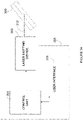
- Figure 1 is an exemplary embodiment of a component 100 formed from a first layer 102 and a second layer 104, seen through a hole 106 drilled therethrough.
- An interface 108 forms a common boundary between the first layer 102 and the second layer 104.
- the component 100 may be an aircraft component, such as a blade, vane, or heat shield.
- the component 100 may be used for other types of vehicles, such as ships, trains, and automobiles, or for other applications, such as power plants, wind turbines, and damns.
- the component 100 may be a composite material, made from two or more constituent materials.
- the component 100 may also comprise one or more primary materials forming a substrate, such as metal, plastic, ceramic, glass, concrete, and/or polymer, and one or more coating materials, such as a thermal barrier coating (TBC), a paint, and/or a lacquer.
- TBC thermal barrier coating
- An exemplary embodiment is illustrated in figure 2 , whereby a component 200 is formed of a first layer 202 that acts as a coating on a second layer 204.
- a hole 206 is shown to have been drilled through the top coating of the first layer 202, the second layer 204, and the bottom coating of the first layer 202.
- a first interface 208a is at the boundary between the top coating of the first layer 202 and the second layer 204
- a second interface 208b is at the boundary between the second layer 204 and the bottom coating of the first layer 202.
- the technique described herein is used to minimize and/or eliminate the cracks that may occur at interfaces 108, 208a, 208b, due to the differences in the properties of the various materials making up the layers of the components 100, 200, and thus the differences in optimal drilling parameters for each layer.
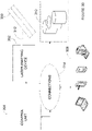
- Figure 3a illustrates an exemplary embodiment of a system for drilling holes in a component 300 composed of at least a first layer and a second layer of material.
- a laser emitting device 302 generates a beam 312 for drilling a hole in the component 300.
- the laser emitting device 302 may include a laser, focusing optics, and any other elements used to generate and emit the laser beam 312, such as a power supply.
- the laser may be a fiber laser, a solid state laser, or a gas laser.
- the laser is a lamp-pumped Nd:YAG laser that emits light with a wavelength of 1064 nm.
- the laser is a multimode (MM) fiber laser that emits light with a wavelength of 1070 nm.
- MM multimode
- the laser emitting device 302 generates pulses in the millisecond range in order to drill through the material using a thermal effect.
- the thermal effect comprises heating, melting, and/or vaporizing of the material.
- the pulses may thus be of a duration that ranges from about 0.1 milliseconds to about 10 milliseconds, and in some embodiments about 0.6 milliseconds to about 1.0 milliseconds.
- Each pulse may have an energy from about 1 Joule to about 150 Joules.
- the hole to be drilled corresponds to the size of the beam 312 , which may range from about 0.1 mm to about 1.0 mm, and in some embodiments from about 0.1 to about 0.5 mm, or from about 0.5 to about 0.75 mm (in diameter).
- the spot size may be changed from layer to layer as a function of the material. The spot size may be maintained constant throughout a given layer.
- a control unit 304 is operatively connected to the laser emitting device 302.
- the connection may be a wired or wireless connection, such that the control unit 304 may transmit command signals to the laser emitting device 302 for generating the laser beam 312.
- a user interface 306 is operatively connected to the control unit 304, for causing the control unit 304 to set pulse parameters for drilling through the layers of the component 300.
- the control unit 304 and the user interface 306 are provided separately and are connected together through a wired or wireless connection.
- the user interface 306 is integrated with the control unit 304 as a single device 308.
- the user interface 306 may be a control panel provided on the device 308.
- the device 308 is a power supply and the control unit 304 is a hardware and/or software component inside the power supply.
- the device 308 is provided externally to the power supply, which is part of the laser emitting device 302.
- Figure 3b is an exemplary embodiment whereby the user interface 306 is a computing device.
- the control unit 304 may be accessible remotely from any one of the computing devices over connections 314.
- the computing device may comprise any device, such as a personal computer, a tablet, a smart phone, or the like, which is configured to communicate over the connections 314 with the control unit 304.
- the control unit 304 may itself be provided directly on one of the computing devices, either as a downloaded software application, a firmware application, or a combination thereof.
- the laser emitting device 302 may also be accessible by the control unit 304 via the connections 314.
- connections 314 may be provided to allow the user interface 306 to communicate with the control unit 304 and/or the control unit 304 to communicate with the laser emitting device 302.
- the connections 314 may comprise wire-based technology, such as electrical wires or cables, and/or optical fibers.
- the connections 314 may also be wireless, such as RF, infrared, Wi-Fi, Bluetooth, and others.
- Connections 314 may therefore comprise a network, such as the Internet, the Public Switch Telephone Network (PSTN), a cellular network, or others known to those skilled in the art. Communication over the network may occur using any known communication protocols that enable devices within a computer network to exchange information.
- PSTN Public Switch Telephone Network
- the connections 314 between the control unit 304 and the user interface 306 may be the same or different from the connections between the laser emitting device 302 and the control unit 304.
- the laser emitting device 302 may be wired to the control unit 304 while the control unit 304 and the user interface 306 communicate wirelessly.
- both connections may be wired or wirelessly but using different technology.
- One or more databases 310 may be integrated directly into the control unit 304 or any one of the devices forming the user interface 306, or may be provided separately therefrom (as illustrated). In the case of a remote access to the databases 310, access may occur via connections 314 taking the form of any type of network, as indicated above.
- the various databases 310 described herein may be provided as collections of data or information organized for rapid search and retrieval by a computer.
- the databases 310 may be structured to facilitate storage, retrieval, modification, and deletion of data in conjunction with various data-processing operations.
- the databases 310 may be any organization of data on a data storage medium, such as one or more servers.
- the databases 310 illustratively have stored therein any one of pulse durations, pulse shapes, material types, material thicknesses, drilling angles, and gas pressures.
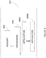
- the control unit 304 illustratively comprises, amongst other things, a plurality of applications 406a ... 406n running on a processor 404 coupled to a memory 402. It should be understood that while the applications 406a ... 406n presented herein are illustrated and described as separate entities, they may be combined or separated in a variety of ways.
- the memory 402 accessible by the processor 404 may receive and store data.
- the memory 402 may be a main memory, such as a high speed Random Access Memory (RAM), or an auxiliary storage unit, such as a hard disk, a floppy disk, or a magnetic tape drive.
- RAM Random Access Memory
- the memory 402 may be any other type of memory, such as a Read-Only Memory (ROM), or optical storage media such as a videodisc and a compact disc.
- the processor 404 may access the memory 402 to retrieve data.
- the processor 404 may be any device that can perform operations on data. Examples are a central processing unit (CPU), a front-end processor, a microprocessor, and a network processor.
- the applications 406a ... 406n are coupled to the processor 404 and configured to perform various tasks.
- Figure 5 is an exemplary embodiment of a method for drilling holes in components composed of at least a first layer and a second layer of material.
- the user interface 306 is responsive to user input for causing the processor 404 of the control unit 304 to set a first layer pulse duration in a millisecond range as per step 502, set a first layer pulse shape defining a varying energy level over time for a first layer pulse as per step 504, set a second layer pulse duration in the millisecond range as per step 506, and set a second layer pulse shape defining a varying energy level over time for a second layer pulse as per step 508.
- the control unit 304 is configured for providing the laser emitting device 302 with command signals for generating at least one first layer pulse having the first layer pulse duration and the first layer pulse shape to drill through the first layer as per step 510, and generating at least one second layer pulse having the second layer pulse duration and the second layer pulse shape to drill through the second layer as per step 512.
- the steps of the method may be repeated for N layers, whereby the Nth layer pulse duration and Nth layer pulse shape are set by the control unit 304, and the Nth layer pulse is applied by the laser emitting device 302.
- the pulse durations and pulse shapes may be set for all layers before any pulses are applied.
- the parameters for a first layer are set, at least one pulse having those parameters is applied, and the parameters for a subsequent layer are set after the first layer has been drilled.
- the operator of the laser emitting device 302 may decide the order of the steps to be performed.
- setting the pulse shape and/or pulse duration comprises receiving a user defined pulse shape and/or duration.
- the user interface 306 may be configured to allow the user to enter a specific value for pulse duration, such as 0.25 ms, using a keypad or a touchscreen.
- the user interface 306 may also be configured to allow the user to shape the pulse as desired, for example using a mouse or a touchscreen.
- the user interface 306 may be configured to allow the user to select from multiple predefined pulse shapes and/or durations, for example using a dropdown menu or a set of numbered input keys. Other means of providing user-defined inputs may also be used.
- setting the pulse shape and/or pulse duration comprises receiving drilling parameters related to the drilling procedure and/or component, to be used by the control unit 304 for selecting pulse shape and/or duration.
- the user may enter, via the user interface 306, information such as a material type for each layer, a material thickness for each layer, a number of layers, a drilling angle, a hole shape, or other information that may be used to determine an optimal pulse shape and/or duration.
- a drilling angle may vary from about 15 to about 90 degrees and this may affect the selection of an optimal pulse shape and/or duration.
- the control unit 304 may be configured to select, based on the received drilling parameters, from a list of predefined pulse durations and/or pulse shapes, based on predetermined configurations.
- control unit 304 may be configured to choose from three predetermined pulse shapes for drilling through metal, and the selection of which one of the three pulse shapes may be made based on additional information such as the thickness of the metal layer.
- a predetermined setting may associate a given pulse shape and/or duration with a given material having a thickness ranging between x and y units. Other such associations may also be provided.
- the control unit 304 may be configured to access a look-up table with the predetermined settings and select, based on the drilling parameters, an optimal pulse shape and/or duration for each layer of material of the component.
- the memory 402 of the control unit 304 is a computer readable medium having stored thereon program code executable by the processor 404 for causing the laser emitting device 302 to drill holes in the component 300 composed of at least a first layer and a second layer of material.
- the program code comprises instructions for setting a first layer pulse duration in a millisecond range; setting a first layer pulse shape defining a varying energy level over time for a first layer pulse; setting a second layer pulse duration in the millisecond range; and setting a second layer pulse shape defining a varying energy level over time for a second layer pulse.
- the program code also comprises instructions for sending a first command to the laser emitting device 302 to generate at least one first layer pulse having the first layer pulse duration and the first layer pulse shape to drill through the first layer; and sending a second command to the laser emitting device 302 to generate at least one second layer pulse with the laser having the second layer pulse duration and the second layer pulse shape to drill through the second layer.
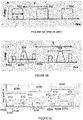
- Figure 6a illustrates a set of pulses 602 in accordance with the prior art.
- Each pulse 602 has a duration t and the pulse train has a period T.
- the frequency of the laser is 1/T.
- Figure 6b illustrates a first exemplary embodiment of a pulse train having two pulses 604, each pulse 604 having a varying level of energy over time.
- a pulse 604 of duration t is segmented into segments, such as segments 606a, 606b, 606c. Each segment is separated by an energy level of zero within the single pulse 604.
- Segment 606a has a same shape as segment 606c but a lower energy level, while segment 606b differs from segments 606a and 606c in shape and energy level.
- Pulse 604 is applied at least once for drilling through a given level, and may be repeated several times. Segmented pulses 604 comprise two or more segments, of varying shape, and/or varying energy level.
- Figure 6c is illustrates an example of pulses for a first layer 608a, a second layer 608b, and a third layer 608c of a given component.
- a pulse 610 is segmented into three segments 616a, 616b, 616c and applied m times to the first layer to drill therethrough.
- a pulse 612 is unsegmented but shaped with a varying energy level over time 618, and applied n times to the second layer to drill therethrough.
- a pulse 614 is segmented into three segments 620a, 620b, 620c and applied p times to the third layer to drill therethrough.
- Each layer is thus drilled through with a pulse shape that is optimal, a pulse duration that is optimal, and a number of pulses that are optimal for the drilling parameters of the layer.
- the pulse shapes and pulse durations are different from one layer to another, depending on the drilling parameters of each layer, and the number of pulses applied may be the same or different from one layer to another, depending on the drilling parameters of each layer.
- setting a second layer pulse shape as per step 508 comprises selecting a pulse shape different from the first layer pulse shape.
- Setting a second layer pulse duration as per step 506 comprises selecting a pulse duration different from the first layer pulse duration.
- Applying at least one second layer pulse as per step 512 may comprise applying a different number of pulses to the second layer than applied to the first layer.
- the method further comprises setting a first layer laser frequency and setting a second layer laser frequency.
- Applying at least one first layer pulse with a laser comprises using the first layer laser frequency and applying at least one second layer pulse with the laser comprises using the second layer laser frequency.
- the frequency of the laser may vary from one layer to another.
- setting a second layer laser frequency may comprise selecting a laser frequency different from the first layer laser frequency.
- pulse shape and/or duration may vary within a same layer of material. For example, a first portion of the first layer may be drilled through using pulses 610, while a second portion of the first layer may be drilled through using pulses 612. This technique may be used, for example, for thicker material where the change in pulse shape and/or duration occurs closer to the interface with the second layer, in order to speed up the drilling process. Only the portion of the first layer that interfaces with the second layer is drilled through using given settings, while the rest of the component is drilled through using other settings. For example, referring to figure 7 , there is illustrated a cross-sectional view of the component 100 of figure 1 .
- Depth d 1 is contained entirely in the first layer 102
- depth d 2 straddles the first layer 102 and the second layer 104
- depth d 3 is contained entirely in the second layer 104. Drilling of depths d 1 and d 3 may occur using same or different beam parameters (i.e. pulse duration, pulse shape), while drilling of depth d 2 may occur using a different set of beam parameters in order to account for the interface 108 between the first layer 102 and the second layer 104.
- beam parameters i.e. pulse duration, pulse shape
- the method of drilling holes in components composed of at least a first layer and a second layer of material comprises setting a first pulse duration in a millisecond range, setting a first pulse shape defining a varying energy level over time for a first pulse, setting a second pulse duration in the millisecond range, and setting a second pulse shape defining a varying energy level over time for a second pulse.
- At least one first pulse having the first pulse duration and the first pulse shape is applied to drill through a portion of the component that does not comprise an interface between the first layer and the second layer
- at least one second pulse having the second pulse shape and the second pulse duration is applied to drill through a portion of the component that comprises the interface between the first layer and the second layer.
- a system for drilling holes in components composed of at least a first layer and a second layer of material comprises a control unit comprising a processor and a memory, and a user interface operatively connected to the control unit.
- the user interface is responsive to user input for causing the processor of the control unit to set a first pulse duration in a millisecond range, set a first pulse shape defining a varying energy level over time for a first pulse, set a second pulse duration in the millisecond range, and set a second pulse shape defining a varying energy level over time for a second pulse.
- the system also comprises a laser emitting device operatively connected to the control unit and configured for receiving command signals from the control unit and applying at least one first pulse having the first pulse duration and the first pulse shape to drill through a portion of the component that does not comprise an interface between the first layer and the second layer and at least one second pulse having the second pulse shape and the second pulse duration to drill through a portion of the component that comprises the interface between the first layer and the second layer.
- a laser emitting device operatively connected to the control unit and configured for receiving command signals from the control unit and applying at least one first pulse having the first pulse duration and the first pulse shape to drill through a portion of the component that does not comprise an interface between the first layer and the second layer and at least one second pulse having the second pulse shape and the second pulse duration to drill through a portion of the component that comprises the interface between the first layer and the second layer.
- a computer readable medium having stored thereon program code executable by a processor for causing a laser emitting device to drill holes in components composed of at least a first layer and a second layer of material comprises instructions for comprises setting a first pulse duration in a millisecond range, setting a first pulse shape defining a varying energy level over time for a first pulse, setting a second pulse duration in the millisecond range, and setting a second pulse shape defining a varying energy level over time for a second pulse.
- the program code also comprises instructions for sending a first command to the laser emitting device to generate at least one first pulse having the first pulse duration and the first pulse shape to drill through a portion of the component that does not comprise an interface between the first layer, and sending a second command to the laser emitting device to generate at least one second pulse having the second pulse shape and the second pulse duration to drill through a portion of the component that comprises the interface between the first layer and the second layer.
Landscapes
- Physics & Mathematics (AREA)
- Optics & Photonics (AREA)
- Engineering & Computer Science (AREA)
- Plasma & Fusion (AREA)
- Mechanical Engineering (AREA)
- Laser Beam Processing (AREA)
Claims (11)
- Verfahren zum Bohren eines Lochs in ein Bauteil (300) mit einem Laser (302), wobei das Bauteil (300) aus mindestens einer ersten Schicht (608a) aus einem ersten Material und einer zweiten Schicht (608b) aus einem zweiten Material besteht, das sich von dem ersten Material unterscheidet, wobei das Verfahren umfasst:Einstellen einer Impulsdauer der ersten Schicht in einem Millisekundenbereich; undEinstellen einer Impulsform der ersten Schicht, die ein zeitlich variierendes Energieniveau für einen Impuls der ersten Schicht definiert;dadurch gekennzeichnet, dass es ferner umfasst:Einstellen einer Impulsdauer der zweiten Schicht im Millisekundenbereich;Einstellen einer Impulsform der zweiten Schicht, die ein zeitlich variierendes Energieniveau für einen Impuls der zweiten Schicht definiert;Erzeugen mindestens eines Impulses (610) der ersten Schicht, der die Impulsdauer der ersten Schicht und die Impulsform der ersten Schicht aufweist, um das Loch durch die erste Schicht (608a) zu bohren; undErzeugen mindestens eines Impulses (612) der zweiten Schicht, der die Impulsdauer der zweiten Schicht und die Impulsform der zweiten Schicht aufweist, um das Loch durch die zweite Schicht (608b) zu bohren,wobei das Einstellen einer Impulsform der zweiten Schicht Auswählen einer Impulsform umfasst, die sich von der Impulsform der ersten Schicht unterscheidet, und das Einstellen einer Impulsdauer der zweiten Schicht Auswählen einer Impulsdauer umfasst, die sich von der Impulsdauer der ersten Schicht unterscheidet,wobei mindestens eines von dem Einstellen einer Impulsform der ersten Schicht und dem Einstellen einer Impulsform der zweiten Schicht Auswählen einer Form umfasst, die mindestens zwei Segmente (616a, 616c), die durch ein Energieniveau von Null getrennt sind, innerhalb eines einzelnen Impulses umfasst, wobei sich die mindestens zwei Segmente (616a, 616c) in mindestens einem von Form und Energieniveau unterscheiden.
- Verfahren nach Anspruch 1, wobei mindestens eines von dem Erzeugen mindestens eines Impulses der ersten Schicht und dem Erzeugen mindestens eines Impulses der zweiten Schicht Erzeugen des einzelnen Impulses mehrere Male umfasst.
- Verfahren nach Anspruch 1 oder 2, wobei das Anwenden mindestens eines Impulses der zweiten Schicht Erzeugen einer anderen Anzahl von Impulsen für die zweite Schicht, als für die erste Schicht erzeugt werden, umfasst.
- Verfahren nach einem vorhergehenden Anspruch, ferner umfassend Einstellen einer Laserfrequenz der ersten Schicht und Einstellen einer Laserfrequenz der zweiten Schicht, und wobei das Erzeugen mindestens eines Impulses der ersten Schicht mit einem Laser Verwenden der Laserfrequenz der ersten Schicht und das Erzeugen mindestens eines zweiten Impulses der zweiten Schicht Verwenden der Laserfrequenz der zweiten Schicht umfasst.
- Verfahren nach Anspruch 4, wobei das Einstellen einer Laserfrequenz der zweiten Schicht Auswählen einer Laserfrequenz umfasst, die sich von der Laserfrequenz der ersten Schicht unterscheidet.
- Verfahren nach einem vorhergehenden Anspruch, wobei das Erzeugen des mindestens einen Impulses der ersten Schicht Erzeugen eines Impulses mit einer ersten Punktgröße umfasst und das Erzeugen des mindestens einen Impulses der zweiten Schicht Erzeugen eines Impulses mit einer zweiten Punktgröße umfasst, die sich von der ersten Punktgröße unterscheidet.
- Verfahren nach einem vorhergehenden Anspruch, ferner umfassend:Bohren durch die erste Schicht (608a) durch Anwenden mindestens eines Impulses (610) der ersten Schicht von einem Laser (302); undBohren durch die zweite Schicht (608b) durch Anwenden mindestens eines Impulses (612) der zweiten Schicht von dem Laser.
- Verfahren nach Anspruch 7, wobei mindestens eines von dem Anwenden mindestens eines Impulses (610) der ersten Schicht und dem Anwenden mindestens eines Impulses (612) der zweiten Schicht ein wiederholtes Anwenden des einzelnen Impulses umfasst, bis durch eine jeweilige eine der ersten Schicht (608a) und der zweiten Schicht (608b) gebohrt wurde.
- Verfahren nach Anspruch 7, wobei mindestens eines von dem Anwenden mindestens eines Impulses (610) der ersten Schicht und dem Anwenden mindestens eines Impulses (612) der zweiten Schicht Anwenden eines einzelnen einen von dem mindestens einen Impuls der ersten Schicht und dem mindestens einen Impuls der zweiten Schicht umfasst, um durch eine jeweilige eine der ersten Schicht (608a) und der zweiten Schicht (608b) zu bohren.
- Verfahren nach Anspruch 8, wobei das Anwenden mindestens eines Impulses (610) der ersten Schicht Anwenden einer ersten Vielzahl von segmentierten und wiederholten Impulsen umfasst, um durch die erste Schicht (608a) zu bohren, und wobei das Anwenden mindestens eines Impulses (612) der zweiten Schicht Anwenden einer zweiten Vielzahl von segmentierten und wiederholten Impulsen umfasst, um durch die zweite Schicht (608b) zu bohren.
- Verfahren nach Anspruch 10, wobei sich die erste Vielzahl von segmentierten und wiederholten Impulsen von der zweiten Vielzahl von segmentierten und wiederholten Impulsen in mindestens einem von der Anzahl von Segmenten pro Impuls und der Dauer jedes Segments unterscheidet.
Applications Claiming Priority (1)
| Application Number | Priority Date | Filing Date | Title |
|---|---|---|---|
| US14/669,071 US20160279737A1 (en) | 2015-03-26 | 2015-03-26 | Laser drilling through multi-layer components |
Publications (3)
| Publication Number | Publication Date |
|---|---|
| EP3072628A1 EP3072628A1 (de) | 2016-09-28 |
| EP3072628B1 EP3072628B1 (de) | 2017-12-20 |
| EP3072628B2 true EP3072628B2 (de) | 2022-07-20 |
Family
ID=55661248
Family Applications (1)
| Application Number | Title | Priority Date | Filing Date |
|---|---|---|---|
| EP16162420.0A Active EP3072628B2 (de) | 2015-03-26 | 2016-03-24 | Laserbohren durch mehrschichtige komponenten unter verwendung von puls in dem millisekundbereich und über zeit variirender energie |
Country Status (3)
| Country | Link |
|---|---|
| US (1) | US20160279737A1 (de) |
| EP (1) | EP3072628B2 (de) |
| CA (1) | CA2924841C (de) |
Families Citing this family (3)
| Publication number | Priority date | Publication date | Assignee | Title |
|---|---|---|---|---|
| DE102017001684A1 (de) * | 2016-11-11 | 2018-05-17 | Rj Lasertechnik Gmbh | Verfahren zum Bohren von Löchern mit einem gepulsten Laser |
| DE102018129329A1 (de) * | 2018-11-21 | 2020-05-28 | Automotive Lighting Reutlingen Gmbh | Verfahren zur Farbenlackabtragenden Laserbearbeitung eines lackierten Werkstücks |
| CN116393847A (zh) * | 2023-04-20 | 2023-07-07 | 江苏大学 | 一种二段式飞秒激光加工气膜孔方法 |
Citations (1)
| Publication number | Priority date | Publication date | Assignee | Title |
|---|---|---|---|---|
| US20020040893A1 (en) † | 2000-10-06 | 2002-04-11 | Hitachi Via Mechanics, Ltd. | Method and apparatus for drilling printed wiring boards |
Family Cites Families (20)
| Publication number | Priority date | Publication date | Assignee | Title |
|---|---|---|---|---|
| US5073687A (en) | 1989-06-22 | 1991-12-17 | Canon Kabushiki Kaisha | Method and apparatus for working print board by laser |
| US5841099A (en) | 1994-07-18 | 1998-11-24 | Electro Scientific Industries, Inc. | Method employing UV laser pulses of varied energy density to form depthwise self-limiting blind vias in multilayered targets |
| US6172331B1 (en) | 1997-09-17 | 2001-01-09 | General Electric Company | Method and apparatus for laser drilling |
| JP2000301372A (ja) | 1999-04-23 | 2000-10-31 | Seiko Epson Corp | 透明材料のレーザ加工方法 |
| US6229113B1 (en) * | 1999-07-19 | 2001-05-08 | United Technologies Corporation | Method and apparatus for producing a laser drilled hole in a structure |
| WO2001076808A2 (en) | 2000-04-11 | 2001-10-18 | Gsi Lumonics Inc. | A method and system for laser drilling |
| KR100530818B1 (ko) | 2001-05-11 | 2005-11-25 | 미쓰비시덴키 가부시키가이샤 | 적층 재료의 레이저 가공 방법 및 장치 |
| DE10307309B4 (de) | 2003-02-20 | 2007-06-14 | Hitachi Via Mechanics, Ltd., Ebina | Vorrichtung und Verfahren zur Bearbeitung von elektrischen Schaltungssubstraten mittels Laser |
| DE112004001527T5 (de) | 2003-08-19 | 2006-07-06 | Electro Scientific Industries, Inc., Portland | Verfahren und Lasersysteme zur Verbindungsbearbeitung unter Verwendung von Laserimpulsen mit speziell zugeschnittenen Leistungsprofilen |
| EP1810774A1 (de) | 2006-01-24 | 2007-07-25 | Siemens Aktiengesellschaft | Verfahren zur Herstellung eines Loches |
| EP1681128A1 (de) | 2005-01-14 | 2006-07-19 | Siemens Aktiengesellschaft | Verfahren zur Herstellung eines Lochs und Vorrichtung |
| US7982161B2 (en) | 2008-03-24 | 2011-07-19 | Electro Scientific Industries, Inc. | Method and apparatus for laser drilling holes with tailored laser pulses |
| US8526473B2 (en) | 2008-03-31 | 2013-09-03 | Electro Scientific Industries | Methods and systems for dynamically generating tailored laser pulses |
| US8598490B2 (en) | 2008-03-31 | 2013-12-03 | Electro Scientific Industries, Inc. | Methods and systems for laser processing a workpiece using a plurality of tailored laser pulse shapes |
| JP5181989B2 (ja) * | 2008-10-03 | 2013-04-10 | ソニー株式会社 | 短パルス光源装置、レーザ駆動方法、光ピックアップ及び光ディスク装置 |
| KR101866579B1 (ko) | 2010-05-04 | 2018-06-11 | 일렉트로 싸이언티픽 인더스트리이즈 인코포레이티드 | 레이저 펄스의 시리즈를 이용하는 드릴링 방법 및 장치 |
| US9120181B2 (en) * | 2010-09-16 | 2015-09-01 | Coherent, Inc. | Singulation of layered materials using selectively variable laser output |
| US8624151B2 (en) | 2011-07-19 | 2014-01-07 | Pratt & Whitney Canada Corp. | Laser drilling methods of shallow-angled holes |
| WO2014085660A1 (en) | 2012-11-29 | 2014-06-05 | Corning Incorporated | Sacrificial cover layers for laser drilling substrates and methods thereof |
| CN103990910B (zh) | 2014-05-20 | 2015-08-05 | 西安交通大学 | 一种带热障涂层涡轮叶片气膜冷却孔的制备方法 |
-
2015
- 2015-03-26 US US14/669,071 patent/US20160279737A1/en not_active Abandoned
-
2016
- 2016-03-22 CA CA2924841A patent/CA2924841C/en active Active
- 2016-03-24 EP EP16162420.0A patent/EP3072628B2/de active Active
Patent Citations (1)
| Publication number | Priority date | Publication date | Assignee | Title |
|---|---|---|---|---|
| US20020040893A1 (en) † | 2000-10-06 | 2002-04-11 | Hitachi Via Mechanics, Ltd. | Method and apparatus for drilling printed wiring boards |
Also Published As
| Publication number | Publication date |
|---|---|
| US20160279737A1 (en) | 2016-09-29 |
| EP3072628B1 (de) | 2017-12-20 |
| EP3072628A1 (de) | 2016-09-28 |
| CA2924841C (en) | 2023-10-31 |
| CA2924841A1 (en) | 2016-09-26 |
Similar Documents
| Publication | Publication Date | Title |
|---|---|---|
| EP3072628B2 (de) | Laserbohren durch mehrschichtige komponenten unter verwendung von puls in dem millisekundbereich und über zeit variirender energie | |
| EP0385911B1 (de) | Laserbohrer | |
| US6804574B2 (en) | Method of using a computer with a laser drilling system | |
| CN110695549B (zh) | 一种激光钻通孔的方法、系统、装置和设备 | |
| JP5659020B2 (ja) | 多重ビーム穿孔システム | |
| US7402774B2 (en) | Flexible scan field | |
| Mukherjee et al. | Parametric optimization of Nd: YAG laser beam machining process using artificial bee colony algorithm | |
| CN101100020B (zh) | 用于在板状的物件中制造穿孔的方法 | |
| JP5587769B2 (ja) | 改良テーパ形状を有するレーザー掘削孔に関する方法及び装置 | |
| US20030006220A1 (en) | Method of ablating an opening in a hard, non-metallic substrate | |
| JP2016521208A (ja) | レーザ溶接システムおよび方法 | |
| TW201223677A (en) | Method and apparatus for drilling using a series of laser pulses | |
| TW201034781A (en) | Minimizing thermal effect during material removal using a laser | |
| TW200950918A (en) | Method and apparatus for laser drilling holes with gaussian pulses | |
| CN114535788B (zh) | 一种静态聚焦的玻璃纳秒激光切孔系统及切孔方法 | |
| CN216284940U (zh) | 一种用于激光诱导击穿光谱的扫描装置 | |
| CN106141451A (zh) | 一种薄膜组件切割方法及装置 | |
| KR20210154813A (ko) | 레이저 가공 장치, 레이저 가공 시스템, 로테이터 유닛 장치, 레이저 가공 방법 및 프로브 카드의 생산 방법 | |
| CN115138988A (zh) | 激光切割方法、系统、设备与计算机可读存储介质 | |
| US10060716B2 (en) | Explosives manipulation using ultrasound | |
| Friedrich et al. | Precision structuring and functionalization of ceramics with ultra-short laser pulses | |
| GB2583090A (en) | Method for joining a first substrate to a second substrate | |
| CN202411659U (zh) | 一种激光钻开锥孔的装置 | |
| Herbst et al. | High-peak power solid state laser for micromachining of hard materials | |
| TWI313206B (en) | A differential diameter hole drilling method |
Legal Events
| Date | Code | Title | Description |
|---|---|---|---|
| PUAI | Public reference made under article 153(3) epc to a published international application that has entered the european phase |
Free format text: ORIGINAL CODE: 0009012 |
|
| AK | Designated contracting states |
Kind code of ref document: A1 Designated state(s): AL AT BE BG CH CY CZ DE DK EE ES FI FR GB GR HR HU IE IS IT LI LT LU LV MC MK MT NL NO PL PT RO RS SE SI SK SM TR |
|
| AX | Request for extension of the european patent |
Extension state: BA ME |
|
| STAA | Information on the status of an ep patent application or granted ep patent |
Free format text: STATUS: REQUEST FOR EXAMINATION WAS MADE |
|
| 17P | Request for examination filed |
Effective date: 20170328 |
|
| RBV | Designated contracting states (corrected) |
Designated state(s): AL AT BE BG CH CY CZ DE DK EE ES FI FR GB GR HR HU IE IS IT LI LT LU LV MC MK MT NL NO PL PT RO RS SE SI SK SM TR |
|
| GRAP | Despatch of communication of intention to grant a patent |
Free format text: ORIGINAL CODE: EPIDOSNIGR1 |
|
| STAA | Information on the status of an ep patent application or granted ep patent |
Free format text: STATUS: GRANT OF PATENT IS INTENDED |
|
| RIC1 | Information provided on ipc code assigned before grant |
Ipc: B23K 101/34 20060101ALN20170824BHEP Ipc: B23K 103/18 20060101ALN20170824BHEP Ipc: B23K 101/00 20060101ALN20170824BHEP Ipc: B23K 26/382 20140101ALI20170824BHEP Ipc: B23K 26/06 20140101AFI20170824BHEP Ipc: B23K 26/0622 20140101ALI20170824BHEP |
|
| RIC1 | Information provided on ipc code assigned before grant |
Ipc: B23K 26/06 20140101AFI20170825BHEP Ipc: B23K 101/34 20060101ALN20170825BHEP Ipc: B23K 26/0622 20140101ALI20170825BHEP Ipc: B23K 101/00 20060101ALN20170825BHEP Ipc: B23K 103/18 20060101ALN20170825BHEP Ipc: B23K 26/382 20140101ALI20170825BHEP |
|
| INTG | Intention to grant announced |
Effective date: 20170921 |
|
| GRAS | Grant fee paid |
Free format text: ORIGINAL CODE: EPIDOSNIGR3 |
|
| GRAA | (expected) grant |
Free format text: ORIGINAL CODE: 0009210 |
|
| STAA | Information on the status of an ep patent application or granted ep patent |
Free format text: STATUS: THE PATENT HAS BEEN GRANTED |
|
| AK | Designated contracting states |
Kind code of ref document: B1 Designated state(s): AL AT BE BG CH CY CZ DE DK EE ES FI FR GB GR HR HU IE IS IT LI LT LU LV MC MK MT NL NO PL PT RO RS SE SI SK SM TR |
|
| REG | Reference to a national code |
Ref country code: GB Ref legal event code: FG4D |
|
| REG | Reference to a national code |
Ref country code: CH Ref legal event code: EP |
|
| REG | Reference to a national code |
Ref country code: IE Ref legal event code: FG4D |
|
| REG | Reference to a national code |
Ref country code: AT Ref legal event code: REF Ref document number: 955924 Country of ref document: AT Kind code of ref document: T Effective date: 20180115 |
|
| REG | Reference to a national code |
Ref country code: DE Ref legal event code: R096 Ref document number: 602016001123 Country of ref document: DE |
|
| REG | Reference to a national code |
Ref country code: FR Ref legal event code: PLFP Year of fee payment: 3 |
|
| REG | Reference to a national code |
Ref country code: NL Ref legal event code: MP Effective date: 20171220 |
|
| PG25 | Lapsed in a contracting state [announced via postgrant information from national office to epo] |
Ref country code: FI Free format text: LAPSE BECAUSE OF FAILURE TO SUBMIT A TRANSLATION OF THE DESCRIPTION OR TO PAY THE FEE WITHIN THE PRESCRIBED TIME-LIMIT Effective date: 20171220 Ref country code: SE Free format text: LAPSE BECAUSE OF FAILURE TO SUBMIT A TRANSLATION OF THE DESCRIPTION OR TO PAY THE FEE WITHIN THE PRESCRIBED TIME-LIMIT Effective date: 20171220 Ref country code: LT Free format text: LAPSE BECAUSE OF FAILURE TO SUBMIT A TRANSLATION OF THE DESCRIPTION OR TO PAY THE FEE WITHIN THE PRESCRIBED TIME-LIMIT Effective date: 20171220 Ref country code: NO Free format text: LAPSE BECAUSE OF FAILURE TO SUBMIT A TRANSLATION OF THE DESCRIPTION OR TO PAY THE FEE WITHIN THE PRESCRIBED TIME-LIMIT Effective date: 20180320 |
|
| REG | Reference to a national code |
Ref country code: LT Ref legal event code: MG4D |
|
| REG | Reference to a national code |
Ref country code: AT Ref legal event code: MK05 Ref document number: 955924 Country of ref document: AT Kind code of ref document: T Effective date: 20171220 |
|
| PG25 | Lapsed in a contracting state [announced via postgrant information from national office to epo] |
Ref country code: HR Free format text: LAPSE BECAUSE OF FAILURE TO SUBMIT A TRANSLATION OF THE DESCRIPTION OR TO PAY THE FEE WITHIN THE PRESCRIBED TIME-LIMIT Effective date: 20171220 Ref country code: BG Free format text: LAPSE BECAUSE OF FAILURE TO SUBMIT A TRANSLATION OF THE DESCRIPTION OR TO PAY THE FEE WITHIN THE PRESCRIBED TIME-LIMIT Effective date: 20180320 Ref country code: LV Free format text: LAPSE BECAUSE OF FAILURE TO SUBMIT A TRANSLATION OF THE DESCRIPTION OR TO PAY THE FEE WITHIN THE PRESCRIBED TIME-LIMIT Effective date: 20171220 Ref country code: RS Free format text: LAPSE BECAUSE OF FAILURE TO SUBMIT A TRANSLATION OF THE DESCRIPTION OR TO PAY THE FEE WITHIN THE PRESCRIBED TIME-LIMIT Effective date: 20171220 Ref country code: GR Free format text: LAPSE BECAUSE OF FAILURE TO SUBMIT A TRANSLATION OF THE DESCRIPTION OR TO PAY THE FEE WITHIN THE PRESCRIBED TIME-LIMIT Effective date: 20180321 |
|
| PG25 | Lapsed in a contracting state [announced via postgrant information from national office to epo] |
Ref country code: NL Free format text: LAPSE BECAUSE OF FAILURE TO SUBMIT A TRANSLATION OF THE DESCRIPTION OR TO PAY THE FEE WITHIN THE PRESCRIBED TIME-LIMIT Effective date: 20171220 |
|
| PG25 | Lapsed in a contracting state [announced via postgrant information from national office to epo] |
Ref country code: ES Free format text: LAPSE BECAUSE OF FAILURE TO SUBMIT A TRANSLATION OF THE DESCRIPTION OR TO PAY THE FEE WITHIN THE PRESCRIBED TIME-LIMIT Effective date: 20171220 Ref country code: CZ Free format text: LAPSE BECAUSE OF FAILURE TO SUBMIT A TRANSLATION OF THE DESCRIPTION OR TO PAY THE FEE WITHIN THE PRESCRIBED TIME-LIMIT Effective date: 20171220 Ref country code: EE Free format text: LAPSE BECAUSE OF FAILURE TO SUBMIT A TRANSLATION OF THE DESCRIPTION OR TO PAY THE FEE WITHIN THE PRESCRIBED TIME-LIMIT Effective date: 20171220 Ref country code: CY Free format text: LAPSE BECAUSE OF FAILURE TO SUBMIT A TRANSLATION OF THE DESCRIPTION OR TO PAY THE FEE WITHIN THE PRESCRIBED TIME-LIMIT Effective date: 20171220 Ref country code: SK Free format text: LAPSE BECAUSE OF FAILURE TO SUBMIT A TRANSLATION OF THE DESCRIPTION OR TO PAY THE FEE WITHIN THE PRESCRIBED TIME-LIMIT Effective date: 20171220 |
|
| PG25 | Lapsed in a contracting state [announced via postgrant information from national office to epo] |
Ref country code: AT Free format text: LAPSE BECAUSE OF FAILURE TO SUBMIT A TRANSLATION OF THE DESCRIPTION OR TO PAY THE FEE WITHIN THE PRESCRIBED TIME-LIMIT Effective date: 20171220 Ref country code: IT Free format text: LAPSE BECAUSE OF FAILURE TO SUBMIT A TRANSLATION OF THE DESCRIPTION OR TO PAY THE FEE WITHIN THE PRESCRIBED TIME-LIMIT Effective date: 20171220 Ref country code: RO Free format text: LAPSE BECAUSE OF FAILURE TO SUBMIT A TRANSLATION OF THE DESCRIPTION OR TO PAY THE FEE WITHIN THE PRESCRIBED TIME-LIMIT Effective date: 20171220 Ref country code: SM Free format text: LAPSE BECAUSE OF FAILURE TO SUBMIT A TRANSLATION OF THE DESCRIPTION OR TO PAY THE FEE WITHIN THE PRESCRIBED TIME-LIMIT Effective date: 20171220 Ref country code: IS Free format text: LAPSE BECAUSE OF FAILURE TO SUBMIT A TRANSLATION OF THE DESCRIPTION OR TO PAY THE FEE WITHIN THE PRESCRIBED TIME-LIMIT Effective date: 20180420 Ref country code: PL Free format text: LAPSE BECAUSE OF FAILURE TO SUBMIT A TRANSLATION OF THE DESCRIPTION OR TO PAY THE FEE WITHIN THE PRESCRIBED TIME-LIMIT Effective date: 20171220 |
|
| REG | Reference to a national code |
Ref country code: DE Ref legal event code: R026 Ref document number: 602016001123 Country of ref document: DE |
|
| PLBI | Opposition filed |
Free format text: ORIGINAL CODE: 0009260 |
|
| PLAX | Notice of opposition and request to file observation + time limit sent |
Free format text: ORIGINAL CODE: EPIDOSNOBS2 |
|
| 26 | Opposition filed |
Opponent name: SAFRAN AIRCRAFT ENGINES Effective date: 20180919 |
|
| PG25 | Lapsed in a contracting state [announced via postgrant information from national office to epo] |
Ref country code: DK Free format text: LAPSE BECAUSE OF FAILURE TO SUBMIT A TRANSLATION OF THE DESCRIPTION OR TO PAY THE FEE WITHIN THE PRESCRIBED TIME-LIMIT Effective date: 20171220 Ref country code: MC Free format text: LAPSE BECAUSE OF FAILURE TO SUBMIT A TRANSLATION OF THE DESCRIPTION OR TO PAY THE FEE WITHIN THE PRESCRIBED TIME-LIMIT Effective date: 20171220 |
|
| REG | Reference to a national code |
Ref country code: BE Ref legal event code: MM Effective date: 20180331 |
|
| REG | Reference to a national code |
Ref country code: IE Ref legal event code: MM4A |
|
| PG25 | Lapsed in a contracting state [announced via postgrant information from national office to epo] |
Ref country code: LU Free format text: LAPSE BECAUSE OF NON-PAYMENT OF DUE FEES Effective date: 20180324 |
|
| PLAF | Information modified related to communication of a notice of opposition and request to file observations + time limit |
Free format text: ORIGINAL CODE: EPIDOSCOBS2 |
|
| PG25 | Lapsed in a contracting state [announced via postgrant information from national office to epo] |
Ref country code: IE Free format text: LAPSE BECAUSE OF NON-PAYMENT OF DUE FEES Effective date: 20180324 |
|
| PG25 | Lapsed in a contracting state [announced via postgrant information from national office to epo] |
Ref country code: BE Free format text: LAPSE BECAUSE OF NON-PAYMENT OF DUE FEES Effective date: 20180331 Ref country code: SI Free format text: LAPSE BECAUSE OF FAILURE TO SUBMIT A TRANSLATION OF THE DESCRIPTION OR TO PAY THE FEE WITHIN THE PRESCRIBED TIME-LIMIT Effective date: 20171220 |
|
| PLBB | Reply of patent proprietor to notice(s) of opposition received |
Free format text: ORIGINAL CODE: EPIDOSNOBS3 |
|
| REG | Reference to a national code |
Ref country code: CH Ref legal event code: PL |
|
| PG25 | Lapsed in a contracting state [announced via postgrant information from national office to epo] |
Ref country code: MT Free format text: LAPSE BECAUSE OF NON-PAYMENT OF DUE FEES Effective date: 20180324 Ref country code: LI Free format text: LAPSE BECAUSE OF NON-PAYMENT OF DUE FEES Effective date: 20190331 Ref country code: CH Free format text: LAPSE BECAUSE OF NON-PAYMENT OF DUE FEES Effective date: 20190331 |
|
| PG25 | Lapsed in a contracting state [announced via postgrant information from national office to epo] |
Ref country code: TR Free format text: LAPSE BECAUSE OF FAILURE TO SUBMIT A TRANSLATION OF THE DESCRIPTION OR TO PAY THE FEE WITHIN THE PRESCRIBED TIME-LIMIT Effective date: 20171220 |
|
| PG25 | Lapsed in a contracting state [announced via postgrant information from national office to epo] |
Ref country code: PT Free format text: LAPSE BECAUSE OF FAILURE TO SUBMIT A TRANSLATION OF THE DESCRIPTION OR TO PAY THE FEE WITHIN THE PRESCRIBED TIME-LIMIT Effective date: 20171220 |
|
| PG25 | Lapsed in a contracting state [announced via postgrant information from national office to epo] |
Ref country code: HU Free format text: LAPSE BECAUSE OF FAILURE TO SUBMIT A TRANSLATION OF THE DESCRIPTION OR TO PAY THE FEE WITHIN THE PRESCRIBED TIME-LIMIT; INVALID AB INITIO Effective date: 20160324 Ref country code: MK Free format text: LAPSE BECAUSE OF NON-PAYMENT OF DUE FEES Effective date: 20171220 |
|
| PG25 | Lapsed in a contracting state [announced via postgrant information from national office to epo] |
Ref country code: AL Free format text: LAPSE BECAUSE OF FAILURE TO SUBMIT A TRANSLATION OF THE DESCRIPTION OR TO PAY THE FEE WITHIN THE PRESCRIBED TIME-LIMIT Effective date: 20171220 |
|
| APBM | Appeal reference recorded |
Free format text: ORIGINAL CODE: EPIDOSNREFNO |
|
| APBP | Date of receipt of notice of appeal recorded |
Free format text: ORIGINAL CODE: EPIDOSNNOA2O |
|
| APAH | Appeal reference modified |
Free format text: ORIGINAL CODE: EPIDOSCREFNO |
|
| APBU | Appeal procedure closed |
Free format text: ORIGINAL CODE: EPIDOSNNOA9O |
|
| REG | Reference to a national code |
Ref country code: CH Ref legal event code: PK Free format text: BERICHTIGUNGEN |
|
| RIN2 | Information on inventor provided after grant (corrected) |
Inventor name: STRACH, LUDWIK |
|
| PUAH | Patent maintained in amended form |
Free format text: ORIGINAL CODE: 0009272 |
|
| STAA | Information on the status of an ep patent application or granted ep patent |
Free format text: STATUS: PATENT MAINTAINED AS AMENDED |
|
| 27A | Patent maintained in amended form |
Effective date: 20220720 |
|
| AK | Designated contracting states |
Kind code of ref document: B2 Designated state(s): AL AT BE BG CH CY CZ DE DK EE ES FI FR GB GR HR HU IE IS IT LI LT LU LV MC MK MT NL NO PL PT RO RS SE SI SK SM TR |
|
| REG | Reference to a national code |
Ref country code: DE Ref legal event code: R102 Ref document number: 602016001123 Country of ref document: DE |
|
| P01 | Opt-out of the competence of the unified patent court (upc) registered |
Effective date: 20230530 |
|
| PGFP | Annual fee paid to national office [announced via postgrant information from national office to epo] |
Ref country code: GB Payment date: 20260220 Year of fee payment: 11 |
|
| PGFP | Annual fee paid to national office [announced via postgrant information from national office to epo] |
Ref country code: DE Payment date: 20260219 Year of fee payment: 11 |
|
| PGFP | Annual fee paid to national office [announced via postgrant information from national office to epo] |
Ref country code: FR Payment date: 20260219 Year of fee payment: 11 |