EP3072460A2 - Verfahren zum aufbringen einer versteifung auf einem chirurgischen klammergerät - Google Patents
Verfahren zum aufbringen einer versteifung auf einem chirurgischen klammergerät Download PDFInfo
- Publication number
- EP3072460A2 EP3072460A2 EP16162067.9A EP16162067A EP3072460A2 EP 3072460 A2 EP3072460 A2 EP 3072460A2 EP 16162067 A EP16162067 A EP 16162067A EP 3072460 A2 EP3072460 A2 EP 3072460A2
- Authority
- EP
- European Patent Office
- Prior art keywords
- buttress
- anvil
- adhesive material
- staple cartridge
- adhesive
- Prior art date
- Legal status (The legal status is an assumption and is not a legal conclusion. Google has not performed a legal analysis and makes no representation as to the accuracy of the status listed.)
- Granted
Links
Images


Classifications
-
- A—HUMAN NECESSITIES
- A61—MEDICAL OR VETERINARY SCIENCE; HYGIENE
- A61B—DIAGNOSIS; SURGERY; IDENTIFICATION
- A61B17/00—Surgical instruments, devices or methods, e.g. tourniquets
- A61B17/10—Surgical instruments, devices or methods, e.g. tourniquets for applying or removing wound clamps, e.g. containing only one clamp or staple; Wound clamp magazines
- A61B17/105—Wound clamp magazines
-
- A—HUMAN NECESSITIES
- A61—MEDICAL OR VETERINARY SCIENCE; HYGIENE
- A61B—DIAGNOSIS; SURGERY; IDENTIFICATION
- A61B17/00—Surgical instruments, devices or methods, e.g. tourniquets
- A61B17/068—Surgical staplers, e.g. containing multiple staples or clamps
-
- A—HUMAN NECESSITIES
- A61—MEDICAL OR VETERINARY SCIENCE; HYGIENE
- A61B—DIAGNOSIS; SURGERY; IDENTIFICATION
- A61B17/00—Surgical instruments, devices or methods, e.g. tourniquets
- A61B17/068—Surgical staplers, e.g. containing multiple staples or clamps
- A61B17/072—Surgical staplers, e.g. containing multiple staples or clamps for applying a row of staples in a single action, e.g. the staples being applied simultaneously
- A61B17/07207—Surgical staplers, e.g. containing multiple staples or clamps for applying a row of staples in a single action, e.g. the staples being applied simultaneously the staples being applied sequentially
-
- A—HUMAN NECESSITIES
- A61—MEDICAL OR VETERINARY SCIENCE; HYGIENE
- A61B—DIAGNOSIS; SURGERY; IDENTIFICATION
- A61B17/00—Surgical instruments, devices or methods, e.g. tourniquets
- A61B17/068—Surgical staplers, e.g. containing multiple staples or clamps
- A61B17/072—Surgical staplers, e.g. containing multiple staples or clamps for applying a row of staples in a single action, e.g. the staples being applied simultaneously
- A61B17/07292—Reinforcements for staple line, e.g. pledgets
-
- A—HUMAN NECESSITIES
- A61—MEDICAL OR VETERINARY SCIENCE; HYGIENE
- A61B—DIAGNOSIS; SURGERY; IDENTIFICATION
- A61B17/00—Surgical instruments, devices or methods, e.g. tourniquets
- A61B2017/00004—(bio)absorbable, (bio)resorbable, resorptive
-
- A—HUMAN NECESSITIES
- A61—MEDICAL OR VETERINARY SCIENCE; HYGIENE
- A61B—DIAGNOSIS; SURGERY; IDENTIFICATION
- A61B17/00—Surgical instruments, devices or methods, e.g. tourniquets
- A61B2017/00831—Material properties
- A61B2017/00951—Material properties adhesive
Definitions
- endoscopic surgical instruments may be preferred over traditional open surgical devices since a smaller incision may reduce the post-operative recovery time and complications. Consequently, some endoscopic surgical instruments may be suitable for placement of a distal end effector at a desired surgical site through the cannula of a trocar. These distal end effectors may engage tissue in a number of ways to achieve a diagnostic or therapeutic effect (e.g., endocutter, grasper, cutter, stapler, clip applier, access device, drug/gene therapy delivery device, and energy delivery device using ultrasonic vibration, RF, laser, etc.). Endoscopic surgical instruments may include a shaft between the end effector and a handle portion, which is manipulated by the clinician.
- Such a shaft may enable insertion to a desired depth and rotation about the longitudinal axis of the shaft, thereby facilitating positioning of the end effector within the patient. Positioning of an end effector may be further facilitated through inclusion of one or more articulation joints or features, enabling the end effector to be selectively articulated or otherwise deflected relative to the longitudinal axis of the shaft.
- endoscopic surgical instruments include surgical staplers. Some such staplers are operable to clamp down on layers of tissue, cut through the clamped layers of tissue, and drive staples through the layers of tissue to substantially seal the severed layers of tissue together near the severed ends of the tissue layers.
- surgical staplers are disclosed in U.S. Pat. No. 4,805,823 , entitled “Pocket Configuration for Internal Organ Staplers,” issued February 21, 1989; U.S. Pat. No. 5,415,334 , entitled “Surgical Stapler and Staple Cartridge,” issued May 16, 1995; U.S. Pat. No. 5,465,895 , entitled “Surgical Stapler Instrument,” issued November 14, 1995; U.S. Pat. No.
- surgical staplers referred to above are described as being used in endoscopic procedures, it should be understood that such surgical staplers may also be used in open procedures and/or other non-endoscopic procedures.
- a surgical stapler may be inserted through a thoracotomy, and thereby between a patient's ribs, to reach one or more organs in a thoracic surgical procedure that does not use a trocar as a conduit for the stapler.
- Such procedures may include the use of the stapler to sever and close a vessel leading to a lung. For instance, the vessels leading to an organ may be severed and closed by a stapler before removal of the organ from the thoracic cavity.
- surgical staplers may be used in various other settings and procedures.
- a surgical stapling instrument may be desirable to equip a surgical stapling instrument with a buttress material to reinforce the mechanical fastening of tissue provided by staples.
- a buttress may prevent the applied staples from pulling through tissue and may otherwise reduce a risk of tissue tearing at or near the site of applied staples.
- Inherent viscosity means the inherent viscosity determined in accordance with ISO 1628 (2009) “Determination of the viscosity of polymers in dilute solution using capillary viscometers.”
- Molecular weight means weight average molecular weight.
- Glass transition temperature of a polymer means the temperature at which the Gibbs free energy is such that the activation energy for the cooperative movement of 50 elements of the polymer is exceeded.
- Crystalstallinity means the crystallinity assessed by differential scanning calorimetry (DSC) using the Pyris 6 DSC from PerkinElmer, Inc.
- “Malleable” in relation to an adhesive means an adhesive that, in response to pressure being applied to it, takes and maintains the form of a surface with which it is engaged.
- Moil means one thousandth of an inch.
- any term is used to describe or quantify the properties of any substance or component, including such terms as "inherent viscosity,” “glass transition temperature,” “crystallinity,” “malleability,” “flowability,” “impermeability,” and “semi impermeability,” then unless the context otherwise requires or specifies, the terms will be understood to apply to the substance or component in the condition in which it is for the time being found in any product or in which it is for the time being being used in any process. Alternatively and in addition, the terms will be understood to apply to the substance or component at standard ambient temperature and pressure (SATP) or under the conditions specified in any protocol for its measurement.
- SATP ambient temperature and pressure
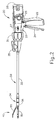
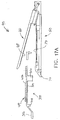
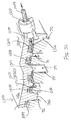
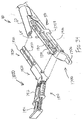
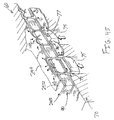
- FIG. 1 depicts an exemplary surgical stapling and severing instrument (10) that includes a handle assembly (20), a shaft assembly (30), and an end effector (40).
- End effector (40) and the distal portion of shaft assembly (30) are sized for insertion, in a nonarticulated state as depicted in FIG. 1 , through a trocar cannula to a surgical site in a patient for performing a surgical procedure.
- a trocar may be inserted in a patient's abdomen, between two of the patient's ribs, or elsewhere.
- instrument (10) is used without a trocar.
- end effector (40) and the distal portion of shaft assembly (30) may be inserted directly through a thoracotomy or other type of incision.
- terms such as “proximal” and “distal” are used herein with reference to a clinician gripping handle assembly (20) of instrument (10).
- end effector (40) is distal with respect to the more proximal handle assembly (20).
- spatial terms such as “vertical” and “horizontal” are used herein with respect to the drawings.
- surgical instruments are used in many orientations and positions, and these terms are not intended to be limiting and absolute.
- handle assembly (20) of the present example comprises pistol grip (22), a closure trigger (24), and a firing trigger (26). Each trigger (24, 26) is selectively pivotable toward and away from pistol grip (22) as will be described in greater detail below.
- Handle assembly (20) further includes an anvil release button (25), a firing beam reverse switch (27), and a removable battery pack (28). These components will also be described in greater detail below.
- handle assembly (20) may have a variety of other components, features, and operabilities, in addition to or in lieu of any of those noted above.
- Other suitable configurations for handle assembly (20) will be apparent to those of ordinary skill in the art in view of the teachings herein.
- shaft assembly (30) of the present example comprises an outer closure tube (32), an articulation section (34), and a closure ring (36), which is further coupled with end effector (40).
- Closure tube (32) extends along the length of shaft assembly (30).
- Closure ring (36) is positioned distal to articulation section (34).
- Closure tube (32) and closure ring (36) are configured to translate longitudinally relative to handle assembly (20). Longitudinal translation of closure tube (32) is communicated to closure ring (36) via articulation section (34). Exemplary features that may be used to provide longitudinal translation of closure tube (32) and closure ring (36) will be described in greater detail below.
- Articulation section (34) is operable to laterally deflect closure ring (36) and end effector (40) laterally away from the longitudinal axis (LA) of shaft assembly (30) at a desired angle ( ⁇ ). End effector (40) may thereby reach behind an organ or approach tissue from a desired angle or for other reasons.
- articulation section (34) enables deflection of end effector (40) along a single plane.
- articulation section (34) enables deflection of end effector along more than one plane.
- articulation is controlled through an articulation control knob (35) which is located at the proximal end of shaft assembly (30).
- Knob (35) is rotatable about an axis that is perpendicular to the longitudinal axis (LA) of shaft assembly (30).
- Closure ring (36) and end effector (40) pivot about an axis that is perpendicular to the longitudinal axis (LA) of shaft assembly (30) in response to rotation of knob (35).
- rotation of knob (35) clockwise may cause corresponding clockwise pivoting of closure ring (36) and end effector (40) at articulation section (34).
- Articulation section (34) is configured to communicate longitudinal translation of closure tube (32) to closure ring (36), regardless of whether articulation section (34) is in a straight configuration or an articulated configuration.
- articulation section (34) and/or articulation control knob (35) are/is constructed and operable in accordance with at least some of the teachings of U.S. Pub. No. 2014/0243801 , entitled “Surgical Instrument End Effector Articulation Drive with Pinion and Opposing Racks,” published August 28, 2014, the disclosure of which is incorporated by reference herein.
- Articulation section (34) may also be constructed and operable in accordance with at least some of the teachings of U.S. Pat. App. No. 14/314,125 , entitled “Articulation Drive Features for Surgical Stapler,” filed June 25, 2014, the disclosure of which is incorporated by reference herein; and/or in accordance with the various teachings below.
- Other suitable forms that articulation section (34) and articulation knob (35) may take will be apparent to those of ordinary skill in the art in view of the teachings herein.
- shaft assembly (30) of the present example further includes a rotation knob (31).
- Rotation knob (31) is operable to rotate the entire shaft assembly (30) and end effector (40) relative to handle assembly (20) about the longitudinal axis (LA) of shaft assembly (30).
- rotation knob (31) is operable to selectively lock the angular position of shaft assembly (30) and end effector (40) relative to handle assembly (20) about the longitudinal axis (LA) of shaft assembly (30).
- rotation knob (31) may be translatable between a first longitudinal position, in which shaft assembly (30) and end effector (40) are rotatable relative to handle assembly (20) about the longitudinal axis (LA) of shaft assembly (30); and a second longitudinal position, in which shaft assembly (30) and end effector (40) are not rotatable relative to handle assembly (20) about the longitudinal axis (LA) of shaft assembly (30).
- shaft assembly (30) may have a variety of other components, features, and operabilities, in addition to or in lieu of any of those noted above.
- at least part of shaft assembly (30) is constructed in accordance with at least some of the teachings of U.S. Pub. No.
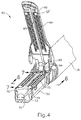
- end effector (40) of the present example includes a lower jaw (50) and a pivotable anvil (60).
- Anvil (60) includes a pair of integral, outwardly extending pins (66) that are disposed in corresponding curved slots (54) of lower jaw (50). Pins (66) and slots (54) are shown in FIG. 5 .
- Anvil (60) is pivotable toward and away from lower jaw (50) between an open position (shown in FIGS. 2 and 4 ) and a closed position (shown in FIGS. 1, 3, and 7A-7B ).
- anvil (60) pivots about an axis that is defined by pins (66), which slide along curved slots (54) of lower jaw (50) as anvil (60) moves toward lower jaw (50).
- the pivot axis translates along the path defined by slots (54) while anvil (60) simultaneously pivots about that axis.
- the pivot axis may slide along slots (54) first, with anvil (60) then pivoting about the pivot axis after the pivot axis has slid a certain distance along the slots (54).
- pivotal movement is encompassed within terms such as “pivot,” “pivots,” “pivotal,” “pivotable,” “pivoting,” and the like.
- some versions may provide pivotal movement of anvil (60) about an axis that remains fixed and does not translate within a slot or channel, etc.
- lower jaw (50) of the present example defines a channel (52) that is configured to receive a staple cartridge (70).
- Staple cartridge (70) may be inserted into channel (52), end effector (40) may be actuated, and then staple cartridge (70) may be removed and replaced with another staple cartridge (70).
- Lower jaw (50) thus releasably retains staple cartridge (70) in alignment with anvil (60) for actuation of end effector (40).
- lower jaw (50) is constructed in accordance with at least some of the teachings of U.S. Pub. No.
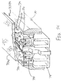
- staple cartridge (70) of the present example comprises a cartridge body (71) and a tray (76) secured to the underside of cartridge body (71).
- the upper side of cartridge body (71) presents a deck (73), against which tissue may be compressed when anvil (60) is in a closed position.
- Cartridge body (71) further defines a longitudinally extending channel (72) and a plurality of staple pockets (74).
- a staple (77) is positioned in each staple pocket (74).
- a staple driver (75) is also positioned in each staple pocket (74), underneath a corresponding staple (77), and above tray (76).
- staple drivers (75) are operable to translate upwardly in staple pockets (74) to thereby drive staples (77) upwardly through staple pockets (74) and into engagement with anvil (60).
- Staple drivers (75) are driven upwardly by a wedge sled (78), which is captured between cartridge body (71) and tray (76), and which translates longitudinally through cartridge body (71).
- Wedge sled (78) includes a pair of obliquely angled cam surfaces (79), which are configured to engage staple drivers (75) and thereby drive staple drivers (75) upwardly as wedge sled (78) translates longitudinally through cartridge (70). For instance, when wedge sled (78) is in a proximal position as shown in FIG.
- staple drivers (75) are in downward positions and staples (77) are located in staple pockets (74).
- wedge sled (78) As wedge sled (78) is driven to the distal position shown in FIG. 7B by a translating knife member (80), wedge sled (78) drives staple drivers (75) upwardly, thereby driving staples (77) out of staple pockets (74) and into staple forming pockets (64) that are formed in the underside (65) of anvil (60).
- staple drivers (75) translate along a vertical dimension as wedge sled (78) translates along a horizontal dimension.
- staple cartridge (70) may be varied in numerous ways.
- staple cartridge (70) of the present example includes two longitudinally extending rows of staple pockets (74) on one side of channel (72); and another set of two longitudinally extending rows of staple pockets (74) on the other side of channel (72).
- staple cartridge (70) includes three, one, or some other number of staple pockets (74) on each side of channel (72).
- staple cartridge (70) is constructed and operable in accordance with at least some of the teachings of U. U.S. Patent App. No. 13/780,106 , entitled "Integrated Tissue Positioning and Jaw Alignment Features for Surgical Stapler," filed February 28, 2013, the disclosure of which is incorporated by reference herein.
- staple cartridge (70) may be constructed and operable in accordance with at least some of the teachings of U.S. Pub. No. 2014/0239044 , entitled “Installation Features for Surgical Instrument End Effector Cartridge,” published August 28, 2014, the disclosure of which is incorporated by reference herein.
- Other suitable forms that staple cartridge (70) may take will be apparent to those of ordinary skill in the art in view of the teachings herein.
- anvil (60) of the present example comprises a longitudinally extending channel (62) and a plurality of staple forming pockets (64).
- Channel (62) is configured to align with channel (72) of staple cartridge (70) when anvil (60) is in a closed position.
- Each staple forming pocket (64) is positioned to lie over a corresponding staple pocket (74) of staple cartridge (70) when anvil (60) is in a closed position.
- Staple forming pockets (64) are configured to deform the legs of staples (77) when staples (77) are driven through tissue and into anvil (60).
- staple forming pockets (64) are configured to bend the legs of staples (77) to secure the formed staples (77) in the tissue.
- Anvil (60) may be constructed in accordance with at least some of the teachings of U.S. Pub. No. 2014/0239042 , entitled “Integrated Tissue Positioning and Jaw Alignment Features for Surgical Stapler,” published August 28, 2014; at least some of the teachings of U.S. Pub. No. 2014/0239036 , entitled “Jaw Closure Feature for End Effector of Surgical Instrument,” published August 28, 2014; and/or at least some of the teachings of U.S. Pub. No. 2014/0239037 , entitled “Staple Forming Features for Surgical Stapling Instrument,” published August 28, 2014, the disclosure of which is incorporated by reference herein.
- Other suitable forms that anvil (60) may take will be apparent to those of ordinary skill in the art in view of the teachings herein.
- a knife member (80) is configured to translate through end effector (40). As best seen in FIGS. 5 and 7A-7B , knife member (80) is secured to the distal end of a firing beam (82), which extends through a portion of shaft assembly (30). As best seen in FIGS. 4 and 6 , knife member (80) is positioned in channels (62, 72) of anvil (60) and staple cartridge (70). Knife member (80) includes a distally presented cutting edge (84) that is configured to sever tissue that is compressed between anvil (60) and deck (73) of staple cartridge (70) as knife member (80) translates distally through end effector (40). As noted above and as shown in FIGS.
- knife member (80) also drives wedge sled (78) distally as knife member (80) translates distally through end effector (40), thereby driving staples (77) through tissue and against anvil (60) into formation.
- wedge sled (78) distally as knife member (80) translates distally through end effector (40), thereby driving staples (77) through tissue and against anvil (60) into formation.
- end effector (40) includes lockout features that are configured to prevent knife member (80) from advancing distally through end effector (40) when a staple cartridge (70) is not inserted in lower jaw (50).
- end effector (40) may include lockout features that are configured to prevent knife member (80) from advancing distally through end effector (40) when a staple cartridge (70) that has already been actuated once (e.g., with all staples (77) deployed therefrom) is inserted in lower jaw (50).
- lockout features may be configured in accordance with at least some of the teachings of U.S. Pub. No.
- anvil (60) is driven toward lower jaw (50) by advancing closure ring (36) distally relative to end effector (40).
- Closure ring (36) cooperates with anvil (60) through a camming action to drive anvil (60) toward lower jaw (50) in response to distal translation of closure ring (36) relative to end effector (40).
- closure ring (36) may cooperate with anvil (60) to open anvil (60) away from lower jaw (50) in response to proximal translation of closure ring (36) relative to end effector (40).
- closure ring (36) and anvil (60) may interact in accordance with at least some of the teachings of U.S. Pub. No.
- handle assembly (20) includes a pistol grip (22) and a closure trigger (24).
- anvil (60) is closed toward lower jaw (50) in response to distal advancement of closure ring (36).
- closure trigger (24) is pivotable toward pistol grip (22) to drive closure tube (32) and closure ring (36) distally.
- suitable components that may be used to convert pivotal movement of closure trigger (24) toward pistol grip (22) into distal translation of closure tube (32) and closure ring (36) relative to handle assembly (20) will be apparent to those of ordinary skill in the art in view of the teachings herein.
- closure trigger (24) When closure trigger (24) reaches a fully pivoted state, such that anvil (60) is in a fully closed position relative to lower jaw (50), locking features in handle assembly (20) lock the position of trigger (24) and closure tube (32), thereby locking anvil (60) in a fully closed position relative to lower jaw (50). These locking features are released by actuation of anvil release button (25).
- Anvil release button (25) is configured and positioned to be actuated by the thumb of the operator hand that grasps pistol grip (22).
- the operator may grasp pistol grip (22) with one hand, actuate closure trigger (24) with one or more fingers of the same hand, and then actuate anvil release button (25) with the thumb of the same hand, without ever needing to release the grasp of pistol grip (22) with the same hand.
- closure trigger (24) with one or more fingers of the same hand
- anvil release button (25) with the thumb of the same hand
- Other suitable features that may be used to actuate anvil (60) will be apparent to those of ordinary skill in the art in view of the teachings herein.
- instrument (10) provides motorized control of firing beam (82).
- instrument (10) includes motorized components that are configured to drive firing beam (82) distally in response to pivoting of firing trigger (26) toward pistol grip (22).
- a motor (not shown) is contained in pistol grip (22) and receives power from battery pack (28). This motor is coupled with a transmission assembly (not shown) that converts rotary motion of a drive shaft of the motor into linear translation of firing beam (82).
- firing beam (82) may only be advanced distally when anvil (60) is in a fully closed position relative to lower jaw (50). After firing beam (82) is advanced distally to sever tissue and drive staples (77) as described above with reference to FIGS.
- the drive assembly for firing beam (82) may be automatically reversed to drive firing beam (82) proximally back to the retracted position (e.g., back from the position shown in FIG. 7B to the position shown in FIG. 7A ).
- the operator may actuate firing beam reverse switch (27), which may reverse the drive assembly for firing beam (82) in order to retract firing beam (82) to a proximal position.
- Handle assembly (20) of the present example further includes a bailout feature (21), which is operable to provide a mechanical bailout allowing the operator to manually retract firing beam (82) proximally (e.g., in the event of power loss while firing beam (82) is in a distal position, etc.).
- the features that are operable to provide motorized actuation of firing beam (82) may be configured and operable in accordance with at least some of the teachings of U.S. Pat. No. 8,210,411 , entitled “Motor-Driven Surgical Instrument,” issued July 3, 2012, the disclosure of which is incorporated by reference herein.
- the features that are operable to provide motorized actuation of firing beam (82) may be configured and operable in accordance with at least some of the teachings of U.S. Pat. No. 8,453,914 , entitled “Motor-Driven Surgical Cutting Instrument with Electric Actuator Directional Control Assembly,” issued June 4, 2013, the disclosure of which is incorporated by reference herein.
- the features that are operable to provide motorized actuation of firing beam (82) may be configured and operable in accordance with at least some of the teachings of U.S. Patent App. No. 14/226,142 , entitled “Surgical Instrument Comprising a Sensor System,” filed March 26, 2014, the disclosure of which is incorporated by reference herein.
- firing beam (82) may be manually actuated in accordance with at least some of the teachings of any other reference cited herein.
- FIG. 8 shows end effector (40) having been actuated through a single stroke through tissue (90).
- cutting edge (84) obscured in FIG. 8
- staple drivers (75) have driven two alternating rows of staples (77) through the tissue (90) on each side of the cut line produced by cutting edge (84).
- Staples (77) are all oriented substantially parallel to the cut line in this example, though it should be understood that staples (77) may be positioned at any suitable orientations.
- end effector (40) is withdrawn from the trocar after the first stroke is complete, the spent staple cartridge (70) is replaced with a new staple cartridge (70), and end effector (40) is then again inserted through the trocar to reach the stapling site for further cutting and stapling. This process may be repeated until the desired amount of cuts and staples (77) have been provided.
- Anvil (60) may need to be closed to facilitate insertion and withdrawal through the trocar; and anvil (60) may need to be opened to facilitate replacement of staple cartridge (70).
- cutting edge (84) may cut tissue substantially contemporaneously with staples (77) being driven through tissue during each actuation stroke.
- cutting edge (84) just slightly lags behind driving of staples (77), such that a staple (47) is driven through the tissue just before cutting edge (84) passes through the same region of tissue, though it should be understood that this order may be reversed or that cutting edge (84) may be directly synchronized with adjacent staples.
- FIG. 8 shows end effector (40) being actuated in two layers (92, 94) of tissue (90), it should be understood that end effector (40) may be actuated through a single layer of tissue (90) or more than two layers (92, 94) of tissue.
- FIG. 8 shows end effector (40) being actuated in two substantially flat, apposed planar layers (92, 94) of tissue, it should be understood that end effector (40) may also be actuated across a tubular structure such as a blood vessel, a section of the gastrointestinal tract, etc.
- FIG. 8 should therefore not be viewed as demonstrating any limitation on the contemplated uses for end effector (40).
- instrument (10) may be used will be apparent to those of ordinary skill in the art in view of the teachings herein.
- instrument (10) may be configured and operable in accordance with any of the various references cited herein. Additional exemplary modifications that may be provided for instrument (10) will be described in greater detail below. Various suitable ways in which the below teachings may be incorporated into instrument (10) will be apparent to those of ordinary skill in the art. Similarly, various suitable ways in which the below teachings may be combined with various teachings of the references cited herein will be apparent to those of ordinary skill in the art. It should therefore be understood that the teachings below may be readily incorporated into the various instruments taught in the various references that are cited herein. It should also be understood that the below teachings are not limited to instrument (10) or devices taught in the references cited herein.
- end effector (40) may be desirable in some instances to equip end effector (40) with a buttress material to reinforce the mechanical fastening of tissue (90) provided by staples (77).
- a buttress may prevent the applied staples (77) from pulling through tissue (90) and may otherwise reduce a risk of tissue (90) tearing at or near the site of applied staples (77).
- a buttress may provide various other kinds of effects such as spacing or gap-filling, administration of therapeutic agents, and/or other effects.
- a buttress may be provided on deck (73) of staple cartridge (70).
- a buttress may be provided on the surface of anvil (60) that faces staple cartridge (70). It should also be understood that a first buttress may be provided on deck (73) of staple cartridge (70) while a second buttress is provided on anvil (60) of the same end effector (40). Various examples of forms that a buttress may take will be described in greater detail below. Various ways in which a buttress may be secured to a staple cartridge (70) or an anvil (60) will also be described in greater detail below.
- FIG. 9 shows an exemplary buttress assembly (100) with a basic composition.
- Buttress assembly (100) of this example comprises a buttress body (102), an upper adhesive layer (104), and a lower adhesive layer (106).
- buttress body (102) comprises a strong yet flexible material configured to structurally support a line of staples (77).
- buttress body (102) may comprise a material including, for example, a hemostatic agent such as fibrin to assist in coagulating blood and reduce bleeding at the severed and/or stapled surgical site along tissue (90).
- buttress body (102) may comprise other adjuncts or hemostatic agents such as thrombin may be used such that buttress body (102) may assist to coagulate blood and reduce the amount of bleeding at the surgical site.
- the hemostatic abilities of such adjuncts may also contribute to the use of such adjuncts as adhesives and sealants.
- the agents may assist to coagulate blood at a surgical site, which allows tissue surrounding such blood to stick together and may prevent leaks along the stapled tissue site, for example.
- Other adjuncts or reagents that may be incorporated into buttress body (102) may further include but are not limited to medical fluid or matrix components.
- buttress body (102) may include natural or genetically engineered absorbable polymers or synthetic absorbable polymers, or mixtures thereof.
- Merely illustrative examples of natural or genetically engineered absorbable polymers are proteins, polysaccharides and combinations thereof.
- proteins that may be used include prothrombin, thrombin, fibrinogen, fibrin, fibronectin, heparinase, Factor X/Xa, Factor VII/VIIa, Factor IX/IXa, Factor XI/XIa, Factor XII/XIIa, tissue factor, batroxobin, ancrod, ecarin, von Willebrand Factor, collagen, elastin, albumin, gelatin, platelet surface glycoproteins, vasopressin, vasopressin analogs, epinephrine, selectin, procoagulant venom, plasminogen activator inhibitor, platelet activating agents, synthetic peptides having hemostatic activity, and/or combinations thereof.
- Polysaccharides include, without limitation, cellulose, alkyl cellulose, e.g. methylcellulose, alkylhydroxyalkyl cellulose, hydroxyalkyl cellulose, cellulose sulfate, salts of carboxymethyl cellulose, carboxymethyl cellulose, carboxyethyl cellulose, chitin, carboxymethyl chitin, hyaluronic acid, salts of hyaluronic acid, alginate, alginic acid, propylene glycol alginate, glycogen, dextran, dextran sulfate, curdlan, pectin, pullulan, xanthan, chondroitin, chondroitin sulfates, carboxymethyl dextran, carboxymethyl chitosan, chitosan, heparin, heparin sulfate, heparan, heparan sulfate, dermatan sulfate, keratan sulfate, carrageenans,
- Examples of synthetic absorbable polymers are aliphatic polyester polymers, copolymers, and/or combinations thereof.
- the aliphatic polyesters are typically synthesized in a ring opening polymerization of monomers including, but not limited to, lactic acid, lactide (including L-, D-, meso and D, L mixtures), glycolic acid, glycolide, ⁇ -caprolactone, p-dioxanone (1,4-dioxan-2-one), and trimethylene carbonate (1,3-dioxan-2-one).
- lactide including L-, D-, meso and D, L mixtures
- glycolic acid glycolide
- ⁇ -caprolactone p-dioxanone
- trimethylene carbonate 1,3-dioxan-2-one
- Buttress body (102) may alternatively comprise a fibrous pad, a foam, a mesh, a weave, and/or another structure capable of containing an adhesive and/or other type of medical fluid.
- buttress body (102) may simply comprise a mesh, a weave, and/or some other structure that is constructed to provide structural support or integrity to a line of staples (77) applied through tissue (90).
- Such a material and structure may be relatively thin and in some instances may be substantially non-compressible.
- buttress body (102) may be constructed in accordance with at least some of the teachings of U.S. Patent Pub. No.
- 2013/0068820 entitled “Fibrin Pad Matrix with Suspended Heat Activated Beads of Adhesive,” published March 21, 2013, the disclosure of which is incorporated by reference herein;
- U.S. Patent Pub. No. 2013/0082086 entitled “Attachment of Surgical Staple Buttress to Cartridge,” published April 4, 2013, the disclosure of which is incorporated by reference herein;
- U.S. Patent Pub. No. 2013/0037596 entitled “Device for Applying Adjunct in Endoscopic Procedure,” published February 14, 2013, the disclosure of which is incorporated by reference herein;
- 2013/0062393 entitled “Resistive Heated Surgical Staple Cartridge with Phase Change Sealant,” published March 14, 2013, the disclosure of which is incorporated by reference herein;
- U.S. Patent Pub. No. 2013/0075446 entitled “Surgical Staple Assembly with Hemostatic Feature,” published March 28, 2013, the disclosure of which is incorporated by reference herein;
- U.S. Patent Pub. No. 2013/0062394 entitled “Surgical Staple Cartridge with Self-Dispensing Staple Buttress,” published March 14, 2013, the disclosure of which is incorporated by reference herein;
- 2013/0075445 entitled “Anvil Cartridge for Surgical Fastening Device,” published March 28, 2013, the disclosure of which is incorporated by reference herein;
- U.S. Patent Pub. No. 2013/0075447 entitled “Adjunct Therapy for Applying Hemostatic Agent,” published March 28, 2013, the disclosure of which is incorporated by reference herein;
- U.S. Patent Pub. No. 2013/0256367 entitled “Tissue Thickness Compensator Comprising a Plurality of Medicaments,” published October 3, 2013, the disclosure of which is incorporated by reference herein.
- buttress body (102) comprises a woven mesh of VICRYL® (polyglactin 910) material by Ethicon US, LLC.
- VICRYL® woven mesh is prepared from a synthetic absorbable copolymer of glycolide and lactide, derived respectively from glycolic and lactic acids. This tightly woven mesh is prepared from uncoated, undyed fiber identical in composition to that used in VICRYL® synthetic absorbable suture, which has been found to be inert, nonantigenic, nonpyrogenic, and to elicit only a mild tissue reaction during absorption.
- VICRYL® woven mesh is intended for use as a buttress to provide temporary support during the healing process.
- any other suitable materials or combinations of materials may be used in addition to or as an alternative to VICRYL® material to form buttress body (102).
- buttress body (102) is formed as a mesh
- buttress body (102) may be formed as a woven mesh, a knitted mesh, or a warp knitted mesh. Regardless of whether buttress body (102) is formed as a mesh or not, buttress body (102) is porous in some examples.
- an adhesive layer (104, 106) may be provided on buttress body (102) in order to adhere buttress body (102) to underside (65) of anvil (60) or deck (73) of staple cartridge (70).
- the material forming adhesive layer (104, 106) may pass through buttress body (102) to reach the outer surface of buttress body (102) that is opposite to the surface on which adhesive layer (104, 106) is disposed.
- upper adhesive layer (104) may be used to secure buttress assembly (100) to the underside (304) of a retainer (300) as will be described in greater detail below; while lower adhesive layer (106) is used to secure buttress assembly (100) to deck (73) of staple cartridge (70).
- lower adhesive layer (106) is configured to provide stronger adherence than upper adhesive layer (104).
- retainer (300) e.g., flanges, clips, etc.
- retainer (300) e.g., flanges, clips, etc.
- retainer (300) e.g., flanges, clips, etc.
- retainer (300) e.g., flanges, clips, etc.
- an adhesive material may be applied to the lower surface of a porous version of buttress body (102) to form lower adhesive layer (106), and some of that adhesive material may pass through buttress body (102) to form upper adhesive layer (104).
- lower adhesive layer (106) ultimately has more adhesive material than upper adhesive layer (104), such that lower adhesive layer (106) provides greater adhesion than upper adhesive layer (104).
- lower adhesive layer (106) may be used to secure buttress assembly (100) to the upper side (302) of a retainer (300) as will be described in greater detail below; while upper adhesive layer (104) is used to secure buttress assembly to underside (65) of anvil (60) of end effector (40).
- upper adhesive layer (104) is configured to provide stronger adherence than lower adhesive layer (106).
- retainer (300) e.g., flanges, clips, etc.
- retainer (300) e.g., flanges, clips, etc.
- retainer (300) are configured to selectively retain buttress assembly (100) against upper side (302) of retainer (300), such that lower adhesive layer (106) is omitted; while upper adhesive layer (104) is used to secure buttress assembly (100) to underside (65) of anvil (60).
- an adhesive material may be applied to the upper surface of a porous version of buttress body (102) to form upper adhesive layer (104), and some of that adhesive material may pass through buttress body (102) to form lower adhesive layer (106).
- upper adhesive layer (104) ultimately has more adhesive material than lower adhesive layer (106), such that upper adhesive layer (104) provides greater adhesion than lower adhesive layer (106).
- each adhesive layer (104, 106), as well as various forms that each adhesive layer (104, 106) may take, will be described in greater detail below.
- buttress assembly (100) may include an impermeable layer or a semi impermeable layer interposed between buttress body (102) and adhesive layer (102), to prevent or restrict migration of adhesive material from adhesive layer (104, 106) into buttress body (100).
- body (102) may be formed of a porous media (e.g., ETHISORBTM by Codman of Raynham, Massachusetts); while the semi impermeable layer may comprise polydioxanone (PDS).
- PDS polydioxanone
- buttress assembly (100) comprises an impermeable layer or a semi impermeable layer to prevent or restrict migration of adhesive material from adhesive layer (104, 106) into buttress body (100)
- a layer may be integrated into buttress body (102) such that the layer permits the adhesive to migrate at least partially into buttress body (102) but not across the full thickness of buttress body (102).
- an impermeable layer or a semi impermeable layer may be integrated into buttress assembly (100) to prevent or restrict migration of an adhesive material will be apparent to those of ordinary skill in the art in view of the teachings herein.
- FIGS. 10-12D show a combination of an exemplary buttress (200) with an exemplary retainer (300).
- Buttress (200) of this example may be constructed in accordance with the teachings above relating to buttress assembly (100) and/or in accordance with other teachings herein.
- Buttress (200) includes an upper side (202) and an underside (204).
- underside (204) includes an adhesive (e.g., like lower adhesive layer (106)) to secure buttress (200) to deck (73) of staple cartridge (70) as described in greater detail below.
- Retainer (300) of this example comprises an upper side (302), an underside (304), a distally projecting tongue (306), and a set of resilient latches (308).
- Upper side (302) and underside (304) are each generally flat in the present example, though it should be understood that upper side (302) and/or underside (304) may include various kinds of features as described elsewhere herein.
- Tongue (306) is configured to provide a grip for an operator, thereby facilitating grasping and handling of retainer (300) during use.
- Latches (308) are configured to releasably secure retainer (300) to lower jaw (50) of end effector (40) as will be described in greater detail below.
- retainer (300) may be formed of molded plastic. Alternatively, retainer (300) may be formed using any other suitable material(s) or technique(s).
- buttress (200) is secured to underside (304) of retainer (300), such that upper side (202) of buttress (200) apposes underside (304) of retainer (300).
- an adhesive such as upper adhesive layer (104) provides releasable adhesion of buttress (200) to underside (304) of retainer (300).
- retainer (300) includes one or more features (e.g., flanges, clips, etc.) that are configured to selectively retain buttress (200) against underside (304) of retainer (300).
- features e.g., flanges, clips, etc.
- the assembly formed by buttress (200) and retainer (300) may be placed before end effector (40) with anvil (60) in the open position.
- a peel-away film (not shown) is positioned over underside (204) of buttress (200) to protect buttress (200) and/or any adhesive material on underside (204) of buttress (200).
- the film is peeled away to expose underside (204) of buttress (200) before reaching the stage shown in FIG. 12A .
- Such a film may comprise polytetrafluoroethylene (PTFE) and/or any other suitable material(s).
- the assembly formed by buttress (200) and retainer (300) may then be placed on staple cartridge (70) such that underside (204) of buttress (200) apposingly contacts deck (73) of staple cartridge (70); and such that latches (308) are releasably secured to lower jaw (50) as shown in FIG. 12B .
- the operator may then drive anvil (60) toward the closed position as shown in FIG. 12C , eventually compressing buttress (200) against deck (73) of staple cartridge (70). Such compression may promote adhesion between underside (204) of buttress (200) and deck (73) of staple cartridge (70).
- anvil (60) After anvil (60) has been used to compress buttress (200) against deck (73) of staple cartridge (70), anvil (60) may be moved back to the open position as shown in FIG. 12D . As also shown in FIG. 12D , retainer (300) may then be pulled away from end effector (40), leaving behind buttress (200) adhered to deck (73) of staple cartridge (70). Upper side (202) of buttress (200) is exposed. End effector (40) is thus loaded with buttress (200) and ready for use in severing and stapling tissue (90).
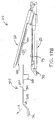
- FIGS. 13A-13C show an end effector (40) loaded with buttress (200) being used to drive a staple (77) through tissue (90).
- tissue (90) is placed between anvil (60) and staple cartridge (70), above buttress (200), with anvil (60) in the open position.
- anvil (60) is driven to the closed position, compressing tissue (90) against buttress (200) and staple cartridge (70).
- End effector (40) is then actuated as described above, driving staple (77) through buttress (200) and tissue (90).
- crown (210) of driven staple (77) captures and retains buttress (200) against layer (94) of tissue (90).
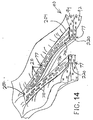
- a series of staples (77) will similarly capture and retain buttress (200) against layer (94) of tissue (90), thereby securing buttress (200) to tissue (90) as shown in FIG. 14 .
- end effector (40) is pulled away from tissue (90) after deploying staples (77) and buttress (200)
- buttress (200) disengages deck (73) of staple cartridge (70), such that buttress (200) remains secured to tissue (90) with staples (77).
- Buttress (200) thus provides structural reinforcement to the lines of staples (77).
- knife member (80) also cuts through a centerline of buttress (200), separating buttress (200) into two sections (230, 240), such that each section (230, 240) remains secured to a respective severed region of tissue (90).
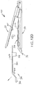
- FIGS. 15-17B show a combination of an exemplary buttress (400) with retainer (300).
- Buttress (400) of this example may be constructed in accordance with the teachings above relating to buttress assembly (100) and/or in accordance with other teachings herein.
- Buttress (400) includes an upper side (402) and an underside (404).
- upper side (402) includes an adhesive (e.g., like upper adhesive layer (1064) to secure buttress (200) to underside (65) of anvil (60) as described in greater detail below.
- buttress (400) is secured to upper side (302) of retainer (300), such that underside (404) of buttress (400) apposes upper side (302) of retainer (300).
- an adhesive such as lower adhesive layer (106) provides releasable adhesion of buttress (400) to upper side (302) of retainer (300).
- retainer (300) includes one or more features (e.g., flanges, clips, etc.) that are configured to selectively retain buttress (400) against upper side (302) of retainer (300).
- features e.g., flanges, clips, etc.
- the assembly formed by buttress (400) and retainer (300) may be placed before end effector (40) with anvil (60) in the open position.
- a peel-away film (not shown) is positioned over upper side (402) of buttress (400) to protect buttress (400) and/or any adhesive material on upper side (402) of buttress (400).
- the film is peeled away to expose upper side (402) of buttress (400) before reaching the stage shown in FIG. 17A .
- Such a film may comprise polytetrafluoroethylene (PTFE) and/or any other suitable material(s).
- the assembly formed by buttress (400) and retainer (300) may then be placed on staple cartridge (70) such that latches (308) are releasably secured to lower jaw (50) as described above.
- the operator may then drive anvil (60) toward the closed position as described above, eventually compressing buttress (400) underside (65) of anvil (60). Such compression may promote adhesion between upper side (402) of buttress (400) and underside (65) of anvil (60).
- anvil (60) may be moved back to the open position as shown in FIG. 17B .
- FIG. 17B As also shown in FIG.
- retainer (300) may then be pulled away from end effector (40), leaving behind buttress (400) adhered to underside (65) of anvil (60). Underside (402) of buttress (400) is exposed. End effector (40) is thus loaded with buttress (400) and ready for use in severing and stapling tissue (90).
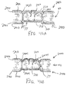
- FIGS. 18A-18C show an end effector (40) loaded with buttress (400) being used to drive a staple (77) through tissue (90).
- tissue (90) is placed between anvil (60) and staple cartridge (70), below buttress (400), with anvil (60) in the open position.
- anvil (60) is driven to the closed position, compressing tissue (90) against buttress (400) and staple cartridge (70).
- End effector (40) is then actuated as described above, driving staple (77) through buttress (400) and tissue (90).
- bent legs (220) of driven staple (77) capture and retains buttress (400) against layer (92) of tissue (90).
- a series of staples (77) will similarly capture and retain buttress (400) against layer (92) of tissue (90), thereby securing buttress (400) to tissue (90) as shown in FIG. 19 .
- anvil (60) is returned to the open position to enable end effector (40) to be pulled away from tissue (90) after deploying staples (77) and buttress (400)
- buttress (400) disengages underside (65) of anvil (60), such that buttress (400) remains secured to tissue (90) with staples (77).
- Buttress (400) thus provides structural reinforcement to the lines of staples (77).
- knife member (80) also cuts through a centerline of buttress (400), separating buttress (400) into two sections (430, 440), such that each section (430, 440) remains secured to a respective severed region of tissue (90).
- retainer (200) may be provided on underside (304) of retainer (300) while buttress (400) is provided on upper side (302) of retainer (300).
- retainer (200) may be provided on underside (304) of retainer (300) while buttress (400) is provided on upper side (302) of retainer (300).
- buttress (200) being provided on deck (73) of staple cartridge (70) and buttress (400) being provided on underside (65) of anvil (60) in the same end effector (400).
- buttress (200) being secured against layer (94) of tissue (90) by crowns (210) of staples (77) while buttress (400) is secured against layer (92) of tissue (90) by bent legs (220) of the same staples (77).
- a buttress assembly (100) may include at least one layer (104, 106) of adhesive material (or other form of adhesive material) that adheres buttress body (102) to either underside (65) of anvil (60) or deck (73) of staple cartridge (70).
- adhesive material or other form of adhesive material
- Such an adhesive material may provide proper positioning of buttress body (102) before and during actuation of end effector (40); then allow buttress body (102) to separate from end effector (40) after end effector (40) has been actuated, without causing damage to buttress body (102) that is substantial enough to compromise the proper subsequent functioning of buttress body (102). It may be desirable to minimize the impact of such an adhesive material on the functioning of firing beam (82) wedge sled (78), and staple drivers (75).
- the adhesive material should allow buttress body (102) to detach easily enough from an actuated end effector (40) to avoid tearing tissue (90) after staples (77) have been fired through the tissue and anvil (60) is moved to the open position.
- the adhesive material may include one or more components that provide a therapeutic effect, hemostatic effect, or other desired effect on tissue (90).
- the adhesive material may fill in at least part of the paths that are formed through tissue (90) and/or buttress body (102) by legs (220) of staple (77) being driven through tissue (90) and buttress body (102).
- the adhesive material for a buttress body (102) may be pressure sensitive.
- the adhesive material may be configured to take the form of surface irregularities of buttress body (102); in addition to or in lieu of taking the form of surface irregularities in underside (65) of anvil (60) and/or deck (73) of staple cartridge (70).
- Suitable adhesive materials may possess various other characteristics in addition to or in lieu of those above. Suitable adhesive materials may also be provided in various different kinds of compositions. Examples of various suitable compositions and configurations that may be used to form and provide an adhesive material for a buttress body (102), as well as various exemplary characteristics that such adhesive material may possess, are described in greater detail below.
- an adhesive material for a buttress body (102) comprises an absorbable synthetic based polymer.
- Various physiomechanical properties of synthetic based polymers may be modified in order to provide different adhesive properties.
- Such variable characteristics include but are not limited to copolymer composition, glass transition temperature (Tg), molecular weight, inherent viscosity (IV), crystallinity, sequence distribution, copolymer chain composition, melting temperature (Tm), and surface tension.
- Tg glass transition temperature
- IV inherent viscosity
- Tm melting temperature
- surface tension Several exemplary combinations of these variables will be provided below, though it should be understood that these examples are merely illustrative. It should also be understood that these examples of adhesive materials may be provided in upper adhesive layer (104).
- these examples of adhesive materials may be provided in lower adhesive layer (106). In addition or in the alternative, these examples of adhesive materials may be otherwise integrated into buttress body (102). It should therefore be understood that the adhesive material need not necessarily constitute a separate layer that is discretely identifiable as being different from a layer defined by buttress body (102).
- the adhesive material is formed by a copolymer of lactide and caprolactone (PLA/PCL).
- This composition may be provided at a ratio in the range of 20/80 to 60/40; or more particularly the range of 35/65 to 50/50.
- This composition may have a glass transition temperature (Tg) that is below 4°C, or more particularly below - 10°C.
- Tg glass transition temperature
- This composition may have a molecular weight in the range of 10,000 g/mol to 145,000 g/mol; or more particularly below 200,000 g/mol.
- the composition may have an inherent viscosity (IV) in the range of 1.0 dL/g to 2.0 dL/g.
- the adhesive material is formed by a copolymer of lactide and trimethylene carbonate (PLA/TMC).
- PLA/TMC lactide and trimethylene carbonate
- This composition may be provided at a ratio in the range of 20/80 to 50/50.
- the other characteristics may be within the same parameters set forth above with respect to the exemplary PLA/PCL composition.
- the PLA/TMC composition may have any other suitable characteristics.
- the adhesive material is formed by a copolymer of trimethylene carbonate and caprolactone (TMC/PCL).
- TMC/PCL trimethylene carbonate and caprolactone
- This composition may be provided at a ratio in the range of 20/80 to 80/20; or more particularly in the range of 50/50 to 60/40.
- This composition may have an inherent viscosity (IV) in the range of 0.3 dL/g to 3.0 dL/g; or more particularly in the range of 0.5 dL/g to 1.0 dL/g.
- This composition may have a crystallinity below 20%; or more particularly below 5%; or more particularly at 0% (i.e., a completely amorphous polymer).
- This composition may have a glass transition temperature (Tg) below 0°C; or more particularly below -20°C.
- the adhesive material is formed by a copolymer of caprolactone and glycolide (PCL/PGA).
- PCL/PGA copolymer of caprolactone and glycolide
- This composition may be provided at a ratio in the range of 45/55 to 85/15; or more particularly in the range of 40/60 to 65/35; or more particularly in the range of 50/50 to 65/35.
- This composition may have an inherent viscosity (IV) in the range of 0.2 dL/g to 3.0 dL/g; or more particularly in the range of 1.0 dL/g to 2.0 dL/g.
- This composition may have a molecular weight in the range of 100,000 g/mol to 200,000 g/mol.
- This composition may have a crystallinity below 20%; or more particularly below 5%; or more particularly at 0% (i.e., a completely amorphous polymer).
- This composition may have a glass transition temperature (Tg) below 0°C; or more particularly below -20°C.
- Tg glass transition temperature
- One particular example of this composition has a ratio of 50/50 PCL/PGA; an inherent viscosity (IV) of 0.2; a molecular weight of 83,000 g/mol; and a glass transition temperature (Tg) of -19.4°.
- compositions has a ratio of 65/35 PCL/PGA; an inherent viscosity (IV) of 1.04 to 1.07; a molecular weight of 110,000 g/mol to 118,000 g/mol; and a glass transition temperature (Tg) in the range of -37.3° to -38.6°.
- exemplary synthetic based polymer compositions that may be used to form the adhesive material include the following: propanediol and caprolactone (PDO/PCL); a combination of propanediol, caprolactone, and trimethylene carbonate (PDO/PCL/TMC), with very low to no crystallinity and a glass transition temperature (Tg) below 0°C; and a homopolymer poly(TMC), with an inherent viscosity (IV) of approximately 0.5 dL/g.
- PDO/PCL propanediol and caprolactone
- Tg glass transition temperature
- IV inherent viscosity
- suitable synthetic based polymer compositions will be apparent to those of ordinary skill in the art in view of the teachings herein.
- the adhesive material may include a blocky copolymer.
- a blocky copolymer that may be used in the adhesive material comprises blocky poly(TMC), with a low glass transition temperature (Tg).
- TMC blocky poly(TMC)
- Tg low glass transition temperature
- the blocky copolymer may be randomized. In some other instances, such as when the copolymer is amorphous (e.g., 0% crystallinity), the blocky copolymer may be ordered.
- the adhesive material may include various kinds of copolymer chain compositions.
- the copolymer chain composition may be branched with relatively short segments. This may further enhance the malleability experience.
- the copolymer chain may be linear.
- the copolymer may be cross-linked or star pattern. However, in versions where the copolymer is cross-linked, it may be desirable for the base copolymer segments to be more amorphous the more that those segment are cross-linked.
- the melting temperature (Tm) is a physiomechanical property of a polymer that may be selected to provide desired adhesive characteristics.
- the lower melting temperature (Tm) of a monomer component could limit the amount of the co-monomer needed to create a desired adhesive effect.
- polydioxanone (PDS) has a melting temperature (Tm) around approximately 110°C and a glass transition temperature (Tg) around approximately - 10°C.
- Tm melting temperature
- Tg glass transition temperature
- PCL caprolactone
- PSA pressure sensitive adhesive
- polydioxanone (PDS) copolymers with polyglycolide (PGA) or lactide (PLA) may provide desired adhesive effects. It may be desirable for such copolymers to have a glass transition temperature (Tg) that is below room temperature; a melting temperature (Tm) that is at or below room temperature; a crystallinity in the range of 10% to 0%; and an inherent viscosity (IV) that is less than 2.0 dL/g, or more particularly less than 1.0 dL/g.
- Tg glass transition temperature
- Tm melting temperature
- IV inherent viscosity
- the adhesive material may comprise a blended copolymer.
- the high and low molecular weight of the same pressure sensitive adhesive (PSA) copolymer may allow for the degradation rate to be adjusted without adjusting the polymer chemistry. As the low molecular weight version breaks down, its acid byproducts would then change the pH and effect the breakdown of the high molecular weight parts.
- Preferred blends of copolymers would include those that will not affect the crystallinity, low melting temperature (Tm), and low glass transition temperature (Tg) of the copolymers.
- the adhesive material may comprise polyurethane.
- the polyurethane may be provided as a pressure sensitive adhesive (PSA).
- PSA pressure sensitive adhesive
- polyurethane based pressure sensitive adhesives PSAs
- PSAs polyurethane based pressure sensitive adhesives
- PSAs may be prepared from isocyanates, polyols, and chain extenders.
- Pressure sensitive adhesives PSAs
- PSAs may also be prepared from 100% solids, waterborne, or solvent borne systems.
- the properties of polyurethane based pressure sensitive adhesives (PSAs) may be controlled by varying the ratio of isocyanates to polyols and chain extenders.
- the polyurethane may be provided in a flowable form.
- a flowable polyurethane based adhesive material may have an inherent viscosity (IV) that is less than 1.0 dL/g, or more particularly less than 0.5 dL/g; a glass transition temperature (Tg) that is in the range of -10°C and 10°C; or more particularly closer to - 10°C; and a consistency similar to that of honey or oil, if desired, with the proper inherent viscosity (IV).
- IV inherent viscosity
- absorbable synthetic based polymers are provided for merely illustrative purposes. Other suitable examples will be apparent to those of ordinary skill in the art in view of the teachings herein. It should also be understood that the foregoing examples of absorbable synthetic based polymers may be readily incorporated into the various teachings and examples provided below. In other words, the foregoing examples of absorbable synthetic based polymers may be readily incorporated into any example herein that refers to an adhesive material.
- the adhesive material comprises a hydrogel.
- the hydrogel may generally comprise a hydrophilic polymer network capable of absorbing and/or retaining fluids.
- An exemplary hydrogel material is glycol methacrylate.
- suitable hydrogel materials may comprise homopolymer hydrogels, copolymer hydrogels, multipolymer hydrogels, interpenetrating polymer hydrogels, and combinations thereof.
- the hydrogel may comprise microgels, nanogels, and combinations thereof.
- the hydrogel may further comprise a non-crosslinked hydrogel, a crosslinked hydrogel, and combinations thereof.
- the hydrogel may comprise chemical crosslinks, physical crosslinks, hydrophobic segments and/or water insoluble segments.
- the hydrogel may be chemically crosslinked by polymerization, small-molecule crosslinking, and/or polymer-polymer crosslinking.
- the hydrogel may be physically crosslinked by ionic interactions, hydrophobic interactions, hydrogen bonding interactions, sterocomplexation, and/or supramolecular chemistry.
- the hydrogel may be substantially insoluble due to the crosslinks, hydrophobic segments and/or water insoluble segments, but be expandable and/or swellable due to absorbing and/or retaining fluids.
- the precursor may crosslink with endogenous materials and/or tissues.
- hydrogels that may be used include multifunctional acrylates, hydroxyethylmethacrylate (HEMA), and elastomeric acrylates.
- a hydrogel adhesive material may be constructed in accordance with at least some of the teachings of U.S. Pat. Pub. No. 2012/0241492 , entitled “Tissue Thickness Compensator Comprising at Least One Medicament,” published September 27, 2012, the disclosure of which is incorporated by reference herein.
- Other suitable ways in which an adhesive material may be provided with hydrogel will be apparent to those of ordinary skill in the art in view of the teachings herein.
- Naturally based polymers that may be used to form an adhesive material include alginate (e.g., calcium alginate, calcium sodium alginate, etc.); hyaluronic acid, collagen (including gelatin), and polysaccharide.
- the polysaccharide may include cellulose, chitin, pectin, or arabinoxylans.
- the cellulose may comprise oxidized regenerated cellulose, carboxy-methylcellulose, carboxyethyl cellulose, hydroxypropyl cellulose, hydroxyethyl cellulose, or oxidized cellulose.
- the chitin may comprise chitosan (e.g., deacetylated chitin) or chitosan salts.
- Some versions of naturally based polymers that may be used to form an adhesive material may include a putty or wax-like material. Some such versions may be non-absorbable and may be similar to a conventional bone wax. For instance, the material may comprise beeswax with one or more of the paraffin, petroleum jelly, isopropyl palmitate, sesame oil, carbolic acid; or any other conventional bone wax composition. Some other versions of a putty or wax-like material that may be used to form an adhesive material for buttress body (102) may be absorbable or resorbable.
- some such versions may comprise HEMASORB® putty by Abyrx, Ink of Irvington, New York, water-soluble alkylene copolymers (e.g., OSTENE by Baxter Healthcare Corporation of Deerfield, Illinois), glycerol, 1-lactide, glycolide, polyethylene glycol (PEG), polyethylene oxide (PEO), or polyolefin elastomer (POE).
- the adhesive material may comprise polyethylene glycol (PEG) or a polyethylene glycol (PEG) copolymer with a molecular weight of less than 20,000 g/mol. Having the molecular weight in such a range may promote passage of the dissolved form of the adhesive through the kidneys.
- the adhesive material may be constructed in accordance with at least some of the teachings of U.S. Pat. No. 2,642,375 , entitled “Hemostatic Compositions,” issued June 16, 1953, the disclosure of which is incorporated by reference herein.
- Some polymer adhesives may include oxidized regenerated cellulose (ORC), which is a hemostatic agent.
- ORC oxidized regenerated cellulose
- a putty or wax-like composition may serve as a carrier for oxidized regenerated cellulose (ORC).
- ORC oxidized regenerated cellulose
- U.S. Patent Pub. No. 2012/0241493 entitled “Tissue Thickness Compensator Comprising Controlled Release and Expansion," published September 27, 2012, the disclosure of which is incorporated by reference herein, discusses various ways in which oxidized regenerated cellulose (ORC) may be incorporated into various compositions. It should be understood that such teachings of U.S. Patent Pub. No. 2012/0241493 may be readily applied herein in the context of incorporating oxidized regenerated cellulose (ORC) into polymer adhesives, including but not limited to the putty or wax-like compositions referred to above.
- one or more adhesive layers (104, 106) with a malleable bioabsorbable polymer adhesive.
- a malleable polymer adhesive may, in response to pressure being applied to it, take the form of a surface with which it is engaged. In other words, if a malleable polymer adhesive is pressed against deck (73) of staple cartridge (70), the malleable polymer adhesive may take the form of the one or more features of the deck (73) that it the malleable polymer adhesive is pressed against.
- the malleable polymer adhesive may take the form of the one or more features of underside (65) that it the malleable polymer adhesive is pressed against. By deforming to the geometry that it is pressed against, the malleable polymer adhesive may adhere to the geometry; and may further provide re-applyable attachment. If the desired positioning of buttress assembly (100) on deck (73) or underside (65) is not achieved, the malleable polymer adhesive may permit buttress assembly (100) to be removed, repositioned, and re-adhered to deck (73) or underside (65). It should be understood that the examples provided below may be malleable at room temperature, such that additional heating or other treatment is not necessary in order to provide malleability.
- Providing the adhesive material in the form of a malleable polymer may minimize the impact of fluids and debris on the adhesion of buttress assembly (100) to deck (73) of staple cartridge (70) or underside (65) of anvil (60).
- the malleable polymer adhesive material may also be hydrophilic (e.g., at least in certain regions of buttress assembly (100)), encouraging adhesion in a wet environment.
- adhesive layer (104, 102) of buttress assembly (100) may include a combination of adhesive material and hydrophobic material in respective localized regions. The hydrophobic material may drive fluids out of the adhesion areas, thereby improving adhesion at the localized regions of adhesive material.
- buttress assembly (100) when a buttress assembly (100) having a malleable bioabsorbable polymer adhesive is sterilized using ethylene oxide at a high temperature, the ethylene oxide gas may act as a plasticizer, increasing the fluidic aspects of the adhesive.
- Buttress assembly (100) may include features that are configured to contain the adhesive at this stage (and/or at other stages where the adhesive may become more fluidic), to maintain the adhesive properties of the adhesive later in its life cycle.
- containment features may be provided by buttress body (102).
- such containment features may be provided by a peel away film layer that is provided on the opposite side of adhesive layer (104, 106), such that the adhesive layer (104, 106) is interposed between buttress body (102) and the peel away film layer.
- Such a peel away film layer may comprise recesses or cavities, etc., as features that provide a predefined space where the viscous fluid adhesive may be retained.
- Other suitable forms of adhesive retention features will be apparent to those of ordinary skill in the art in view of the teachings herein.
- the below examples include various compositions of malleable bioabsorbable polymer adhesives and various exemplary configurations through which a malleable bioabsorbable polymer adhesive may be combined with a buttress body (102).
- the adhesive material comprises a synthetic based polymer such as those referred to herein.
- naturally based polymers may be incorporated with the below teachings.
- the below examples may be readily applied to underside (65) of anvil (60).
- the same examples may be readily applied to deck (73) of staple cartridge (70).
- the polymer adhesive is provided in a thin layer having properties in the range of malleable to flowable (high viscosity), with a tacky surface contact.
- such polymer adhesives have a low inherent viscosity (IV) with low crystallinity.
- One such composition may comprise a 65/35 copolymer of caprolactone and glycolide (PCL/PGA).
- Another such composition may comprise a 65/35 copolymer of trimethylene carbonate and caprolactone (TMC/PCL).
- TMC/PCL trimethylene carbonate and caprolactone
- Another such composition may comprise a 75/25 copolymer of lactide and caprolactone (PLA/PCL).
- Another such composition may comprise a copolymer of trimethylene carbonate and lactide (TMC/PLA).
- Some of the putty or wax-like compositions previously referred to may be used to provide a malleable polymer adhesive.
- Absorbable versions of such compositions include HEMASORB® putty by Abyrx, Ink of Irvington, New York, water-soluble alkylene copolymers (e.g., OSTENE by Baxter Healthcare Corporation of Deerfield, Illinois), glycerol, 1-lactide, glycolide, and polyethylene glycol (PEG).
- Non-absorbable versions of such compositions include beeswax with one or more of the paraffin, petroleum jelly, isopropyl palmitate, sesame oil, carbolic acid; or any other conventional bone wax composition.
- Some malleable polymer adhesives, including but not limited to the putty or wax-like compositions may include oxidized regenerated cellulose (ORC), as further noted above.
- malleable polymer compositions that may be used to adhere buttress body (102) to underside (65) of anvil (60) or deck (73) of staple cartridge (70).
- other suitable compositions may include various other compositions referred to herein and variations thereof.
- a malleable absorbable polymer adhesive may be provided as a thin film on buttress body (102).
- a copolymer adhesive film layer (104, 106) is compression molded in a 65/35 caprolactone and glycolide (PCL/PGA) form to a thickness in the range of 75 mils to 250 mils.
- the compressed adhesive film layer (104, 106) can then be pressed into adhesive contact with buttress body (102).
- a polytetrafluoroethylene (PTFE) film may be applied to the exposed face of adhesive film layer (104, 106) to protect the face of adhesive film layer (104, 106).
- the polytetrafluoroethylene (PTFE) film may be removed to expose the adhesive film layer (104, 106).
- the exposed adhesive film layer (104, 106) may then be pressed against deck (73) of staple cartridge (70) or underside (65) of anvil (60), thereby adhering buttress assembly (100) to deck (73) of staple cartridge (70) or underside (65) of anvil (60).
- a fluidic composition of 50/50 caprolactone and glycolide (PCL/PGA) is heated and painted onto buttress body (102), thereby providing a thin adhesive film layer (104, 106).
- the adhesive film layer (104, 106) behaves like a thick compressed film element to adhere to deck (73) of staple cartridge (70) or underside (65) of anvil (60).
- a polytetrafluoroethylene (PTFE) film may be used to selectively protect and expose the adhesive film layer (104, 106).
- a malleable absorbable polymer adhesive is provided as a thin film on buttress body (102)
- adhesion may occur as the thin adhesive film layer (104, 106) is deformed due to compression against deck (73) of staple cartridge (70) or underside (65) of anvil (60).
- the adhesive film layer (104, 106) has a tacky surface condition but the adhesion may actually be provided through a combination of cohesion, surface tension, deformation of the contact surface to mate directly to the geometry of deck (73) of staple cartridge (70) or underside (65) of anvil (60), and some tacky adhesion, rather than just adhesion alone.
- buttress assembly (100) includes a geometry and/or other features that improve adhesion and/or prevent inadvertent flow of adhesive material into undesirable regions.
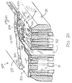
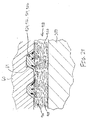
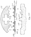
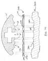
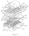
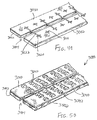
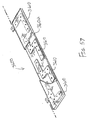
- FIGS. 20-21 show an exemplary buttress assembly (500) that is configured to provide such properties.
- Buttress assembly (500) of this example comprises a buttress body (502), an intermediate layer (510), and an adhesive layer (520).
- Buttress body (502) may be configured and operable just like buttress body (102) described above.
- Adhesive layer (520) may comprise any of the various adhesive materials referred to herein, including but not limited to any of the various absorbable malleable polymer compositions.
- Intermediate layer (510) is interposed between buttress body (502) and adhesive layer (520). At least a portion of intermediate layer (510) may be impermeable or semi impermeable as described above, to prevent or restrict migration of adhesive material from adhesive layer (520) into buttress body (502). Intermediate layer (510) is configured to promote and prevent adhesion of the material forming adhesive layer (520) at different regions.
- adhesive layer (520) includes an opening (522) over each staple pocket (74) of staple cartridge (70).
- Openings (522) are configured to prevent the material forming adhesive layer (520) from entering or otherwise covering staple pockets (74), thereby preventing the adhesive layer from inhibiting the exit of staples (77) from staple pockets (74).
- Adhesive layer (520) further includes an opening (524) in the form of a longitudinal channel over channel (72) of staple cartridge (70). Opening (524) is configured to prevent the material forming adhesive layer (520) from entering or otherwise covering channel (72), thereby preventing the adhesive layer from inhibiting the distal motion of firing beam (82) through channel (72).
- openings (522) may be sized and positioned to prevent the material forming adhesive layer (520) from entering or otherwise covering staple forming pockets (64).
- opening (524) may be configured to prevent the material forming adhesive layer (520) from entering or otherwise covering channel (62).
- openings (522, 524) are formed due to the presence of features of intermediate layer (510) that are configured to prevent adhesion of the adhesive material.
- features of intermediate layer keep the adhesive material away from the regions where openings (522, 524) are intended to be formed.
- such features may comprise a micro and/or macro surface finish features and/or other kinds of features.
- intermediate layer (510) may comprise macro standing features that keep the adhesive material away from the regions where openings (522, 524) are intended to be formed.
- a die or other device may be used to keep the adhesive material away from the regions where openings (522, 524) are intended to be formed.
- a die may be removed at any suitable time before buttress assembly (500) is applied to deck (73) of staple cartridge (70) or underside (65) of anvil (60).
- Other suitable ways in which openings (522, 524) may be formed will be apparent to those of ordinary skill in the art in view of the teachings herein.
- intermediate layer (510) may include a surface finish and/or other surface features that is/are configured to promote adhesion of the adhesive material to the regions outside of openings (522, 524).
- FIG. 21 shows an example of a set of staples (77) driven through tissue (90), with two buttress assemblies (500) secured to the tissue (90).
- one buttress assembly (500) had been secured to deck (73) of staple cartridge (70) while another buttress assembly (500) had been secured to underside (65) of anvil (60).
- openings (522) are sized to accommodate staples (77) at each buttress assembly (500).
- neither crowns (210) nor legs (220) of staples (77) have passed through any of the material forming adhesive layer (520) in either buttress assembly (500).
- FIGS. 22A-22B show an exemplary buttress assembly (600) comprising a buttress body (602) and a set of adhesive rods (620).
- Buttress body (602) may be configured and operable just like buttress body (102) described above.
- Adhesive rods (620) may comprise any of the various adhesive materials referred to herein, including but not limited to any of the various absorbable malleable polymer compositions.
- adhesive layer (620) may comprise one of the putty or wax-like compositions previously referred to.
- Buttress assembly (600) is shown as being used in combination with a staple cartridge (670) that is substantially similar to staple cartridge (70).
- staple cartridge (670) of this example comprises upwardly extending, U-shaped lip members (680) around the end of each staple pocket (674).
- Staple cartridge (670) is otherwise identical to staple cartridge (70).
- Adhesive rods (620) are oriented to extend longitudinally, such that adhesive rods are parallel to each other and parallel to the longitudinal axis defined by staple cartridges (70). Adhesive rods (620) are positioned laterally between lip members (680), such that lip members (680) are configured to maintain the positioning of adhesive rods (620).
- adhesive rods (620) are cylindrical in form, each having a substantially circular cross section. Buttress body (602) is then pressed against adhesive rods (520), causing adhesive rods (620) to malleably deform as shown in FIG. 22B .
- adhesive rods (620) may be positioned on underside (65) of anvil (60) to secure a buttress body (602) to underside (65) of anvil (60). Such adhesive rods (620) may be laterally positioned between longitudinally extending rows of staple forming pockets (64).
- FIG. 23 shows an exemplary alternative buttress assembly (700) with an exemplary alternative retainer (750).
- Buttress assembly (700) of this example comprises a buttress body (702) and a plurality of discretely formed adhesive regions (720).
- Buttress body (702) may be configured and operable just like buttress body (102) described above.
- Adhesive regions (720) may comprise any of the various adhesive materials referred to herein, including but not limited to any of the various absorbable malleable polymer compositions. In the present example, adhesive regions (720) are square shaped, though it should be understood that adhesive regions (720) may have any other suitable configuration.
- Retainer (750) comprises a base member (752) having an upper surface (754), a plurality of latches (756), and a distally projecting tongue (758) that is configured to facilitate grasping and manipulation of retainer (750).
- Retainer (750) also includes an upper member (760) that is secured to base member (752) by a living hinge (770).
- Upper member (760) has an upper surface (762) that is configured to engage buttress body (702).
- a plurality of openings (764) are formed through upper member (760). Openings (764) are configured and arranged to correspond with the configuration and arrangement of adhesive regions (720) when buttress assembly (700) is laid over upper surface (762).
- a plurality of rigid posts (766) extend upwardly from upper surface (754) of base member (752). Posts (766) are configured and arranged to correspond with the configuration and arrangement of openings (764) and adhesive regions (720).
- retainer (750) may be removably secured to end effector (40) in a manner similar to retainer (300) described above, with latches (756) releasably engaging lower jaw (50).
- upper member (760) is spaced away from upper surface (754) of base member (752) due to a resilient bias imposed by living hinge (770).
- Retainer (750) may thus be configured as shown in FIG. 24A , where anvil (60) is brought into initial contact with buttress assembly (700). As shown, an adhesive region (720) of buttress assembly (700) is positioned directly under a pair of staple forming pockets (64).
- adhesive region (720) may be positioned under some other feature of underside (65) of anvil (60).
- the resilient bias provided by living hinge (770) ensures that adhesive region (720) contacts the appropriate region of underside (65) of anvil (60) before anvil (60) reaches a fully closed position.
- the resilient bias provided by living hinge (770) may also provide and maintain a minimum consistent pressure during the closure of anvil (60) to enhance the attachment of adhesive region (720) to underside (65) of anvil (60).
- anvil (60) As anvil (60) is driven further toward the closed position, anvil (60) bears down on adhesive region (720) and upper member (760), thereby causing upper member (760) to pivot toward base member (752).
- post (764) passes through opening (762).
- the height of post (764) is greater than the vertical thickness of upper member (760), such that the top of post (764) protrudes above upper surface (762) of upper member (760) when upper member (760) is driven downwardly into apposition with upper surface (754) of base member (752).
- the protruding top of post (764) provides an opposing force against the underside of buttress body (702), in the region beneath adhesive region (720).
- Adhesive region (720) is thus compressed between underside (65) of anvil (60) and the region of buttress body (702) just above the top of post (764). This compression results in malleable deformation of adhesive region (720), such that the material forming adhesive region takes the form of the corresponding staple forming pockets (64), as shown in FIG. 24B .
- FIG. 25 shows an exemplary buttress assembly (800) comprising a buttress body (802) and a plurality of adhesive regions (820, 822, 824, 830).
- Buttress body (802) may be configured and operable just like buttress body (102) described above.
- Adhesive regions (820, 822, 824, 830) may comprise any of the various adhesive materials referred to herein, including but not limited to any of the various absorbable malleable polymer compositions.
- a first adhesive region (820) extends laterally along a proximal portion of buttress body (802), spanning substantially the full width of buttress body (802).
- a second adhesive region (822) is located near the longitudinal and lateral center of buttress body (802).
- Third and fourth adhesive regions (824) extend longitudinally along each lateral side of buttress body (802).
- Fifth and sixth adhesive regions (830) are located at the distal end of buttress body (802), at the corners.
- Each adhesive region (830) includes a thick portion (832) and a thin portion (834). It should be understood that any of the other adhesive regions (822, 824, 830) may also have thick and thin portions.
- some adhesive regions (820, 822, 824, 830) may be thicker than other adhesive regions (820, 822, 824, 830).
- some adhesive regions (820, 822, 824, 830) may have a greater density than other adhesive regions (820, 822, 824, 830).
- any one of the adhesive regions (820, 822, 824, 830) may have varying intra-region density.
- one or more adhesive layers (104, 106) with a bioabsorbable polymer adhesive having a low inherent viscosity (IV).
- the below examples include various exemplary configurations through which a bioabsorbable polymer adhesive having a low inherent viscosity (IV) may be combined with a buttress body (102).
- the adhesive material comprises a synthetic based polymer such as those referred to herein.
- naturally based polymers may be incorporated with the below teachings.
- a suitable adhesive copolymer having a low inherent viscosity (IV) is a 65/35 composition of caprolactone and glycolide (PCL/PGA) having low crystallinity, with an inherent viscosity (IV) in the range of about 0.8 dL/g to about 1.0 dL/g.
- a 65/35 composition of caprolactone and glycolide (PCL/PGA) with a low inherent viscosity (IV) and having a molecular weight near or equal to that of Monocryl (which has a 75/25 composition of caprolactone and glycolide (PCL/PGA)) may also provide suitable adhesive properties.
- a suitable adhesive copolymer having a low inherent viscosity is a composition of caprolactone and glycolide (PCL/PGA) with an inherent viscosity (IV) in the range of 0.2 dL/g to 1.0 dL/g.
- Another example of a suitable adhesive copolymer having a low inherent viscosity (IV) is a composition of trimethylene carbonate and caprolactone (TMC/PCL) with an inherent viscosity (IV) in the range of 0.3 dL/g to 1.0 dL/g, or more particularly in the range of 0.5 dL/g to 1.0 dL/g.
- Another suitable adhesive having a low inherent viscosity (IV) is caprolactone (PCL) with an inherent viscosity (IV) in the range of 0.2 dL/g to 0.9 dL/g.
- Inherent viscosity (IV) reflects a measurement of molecular size. It is based on the flow time of a polymer solution through small capillary channels over time. The inherent viscosity (IV) and molecular weight of a polymer are related, but that relational agreement is different for each copolymer composition. For instance, the correlation of inherent viscosity (IV) to molecular weight may be logarithmic with only a small midsection of the curve being linear. This logarithmic correlation may differ as the copolymer composition differs. It is not necessarily required to have a low molecular weight copolymer in order to manifest adhesive and malleable properties. Low molecular weight copolymers may also have shortened degradation cycles and reduced structural strength.
- a suitable adhesive material having a low inherent viscosity (IV) may have a molecular weight in the range of 11,000 g/mol to 30,000 g/mol. The molecular weight may be higher in cases where the inherent viscosity (IV) is particularly low.
- a suitable adhesive material may comprise a 50/50 composition of caprolactone and glycolide (PCL/PGA) with an inherent viscosity of about 0.2 dL/g and a molecular weight of about 83,000 g/mol.
- one or more adhesive layers (104, 106) with a bioabsorbable polymer adhesive having a low glass transition temperature (Tg).
- Tg glass transition temperature
- the below examples include various exemplary configurations through which a bioabsorbable polymer adhesive having a low glass transition temperature (Tg) may be combined with a buttress body (102).
- the adhesive material comprises a synthetic based polymer such as those referred to herein.
- naturally based polymers may be incorporated with the below teachings.
- Glass transition temperature (Tg) is the temperature at which the mechanical properties of a copolymer change dramatically from a flowable adhesive to a brittle plastic.
- the glass transition temperature (Tg) is lower than the melting point of the crystalline form of the same copolymer.
- the glass transition temperature (Tg) may be indicative of how the polymer behaves under ambient conditions.
- the melting temperature (Tm) may be referred to as the "first-order transition,” which is where the polymer changes state from solid to liquid. Crystalline polymers have a true melting point, which is the temperature at which the crystallites melt and the total mass of plastic becomes amorphous.
- Amorphous polymers do not have a true melting point, but they do have a first-order transition where their mechanical behavior transitions from a rubbery nature to viscous rubbery flow.
- Suitable polymers for use in forming adhesive layer (102, 104) may have a percent of crystallinity making them behave both amorphically and crystally.
- the glass transition temperature (Tg) can be effected by composition, polymer chain configuration and stiffness, molecular weight, viscosity, shear modulus, heat capacity, thermal expansion, cross-linking and other factors. It is therefore possible to have a relatively low glass transition temperature (Tg) material composition that does not always correspond to low molecular weight or low inherent viscosity (IV).
- the glass transition temperature (Tg) may be below about 0°C, and more particularly below about -20°C.
- a suitable adhesive copolymer having a low glass transition temperature (Tg) is a 65/35 composition of caprolactone and glycolide (PCL/PGA), with a low inherent viscosity (IV) and low crystallinity, having a glass transition temperature (Tg) of less than about -35°C.
- a suitable adhesive copolymer having a low glass transition temperature (Tg) is a 50/50 composition of caprolactone and glycolide (PCL/PGA), with a low inherent viscosity (IV) and low crystallinity, having a glass transition temperature (Tg) of less than about -19°C.
- Tg glass transition temperature
- TMC/PCL trimethylene carbonate and caprolactone
- IV low inherent viscosity
- Tg glass transition temperature below about 0°C and more particularly below about -20°C.
- the glass transition temperature (Tg) may be below about 4°C, and more particularly below about -10°C.
- the glass transition temperature (Tg) may be below about -60°C.
- the glass transition temperature (Tg) may be below about -35°C.
- a suitable adhesive copolymer having a low glass transition temperature (Tg) is a 50/50 composition of caprolactone and glycolide (PCL/PGA), with a low inherent viscosity (IV) and low crystallinity.
- a biologically derived extracellular matrix (ECM) as buttress body (102) with an infused viscous absorbable copolymer as an adhesive layer (104, 106) on upper or lower surfaces of buttress body (102).
- ECM biologically derived extracellular matrix
- the below examples include various exemplary configurations through which a buttress assembly (100) may be formed by a combination of a biologically derived extracellular matrix (ECM) with one or more infused viscous absorbable copolymer adhesive materials.
- the adhesive material comprises a natural based polymer such as those referred to herein.
- synthetic based polymers may be incorporated with the below teachings.
- FIGS. 26-28 show an exemplary buttress assembly (900) that comprises a buttress body (902) and a plurality of discretely formed adhesive regions (920, 922, 924, 926).
- Buttress body (902) may be configured and operable just like buttress body (102) described above.
- Buttress body (902) of this particular example comprises a biologically derived extracellular matrix (ECM) such as collagen.
- Adhesive regions (920, 922, 924, 926) may comprise any of the various adhesive materials referred to herein.
- a first pair of proximal adhesive regions (920) are positioned at respective proximal corners of buttress body (902).
- a second pair of lateral adhesive region (922) are located near the longitudinal and lateral center of buttress body (902).
- a third pair of adhesive regions (924) are positioned at respective proximal corners of buttress body (902).
- a fourth pair of adhesive regions (926) extend longitudinally along the lateral mid-region of buttress body (902), such that adhesive regions (926) are positioned to run alongside channel (62) of anvil (60) or channel (72) of staple cartridge (70). While adhesive regions (920, 922, 924, 926) are provided in a particular pattern in this example, it should be understood that buttress assembly (900) may instead have adhesive regions in any other suitable pattern. It should also be understood that buttress assembly (900) may have a single layer of adhesive material spanning along the full surface of buttress body (902), without having discretely formed adhesive regions. Other suitable configurations will be apparent to those of ordinary skill in the art in view of the teachings herein.
- FIG. 27 shows how buttress body (902) provides a lattice defining a plurality of cells (908). Due to the presence of cells (908) and the porous nature of buttress body (902), some of the adhesive material forming adhesive regions (920, 922, 924, 926) has entered some of those cells (908), thereby partially infusing buttress body (902) with the adhesive material. In other words, buttress body (902) acts like a sponge absorbing the adhesive material, allowing the adhesive material to deform, surround, and essentially grab hold of the lattice connections within buttress body (902).
- the adhesive material is initially applied to buttress body (902) when the adhesive material is in a relatively high viscous form. Buttress assembly (900) is then heated to increase the viscosity of the adhesive material, causing the adhesive material to enter some of the cells (908) of buttress body (902). Buttress assembly (900) is then cooled or allowed to cool, causing the viscosity of the adhesive material to increase back to its previous state. Buttress assembly (900) may then be heated again as buttress assembly (900) is being applied to end effector (40) as described in greater detail below. In some other versions, the adhesive material already has a low enough viscosity to enter cells (908) when the adhesive material is applied, without requiring the adhesive material to be heated.
- the adhesive material may wick into cells (908) of buttress body (902).
- a protective film e.g., polytetrafluoroethylene (PTFE)
- PTFE polytetrafluoroethylene
- FIG. 28 shows buttress assembly (900) being compressed between retainer (300) and anvil (60). As shown, this compression crushes the lattice structure of buttress body (902), collapsing cells (908) and thereby driving adhesive material out of buttress body (902) and into staple forming pockets (64) (and/or into other surface features of underside (65)). This compression may be provided by closing anvil (60) against buttress assembly (900) and retainer (300) as described above.
- retainer (300) and/or buttress assembly (900) may be heated just before buttress assembly (900) is compressed between retainer (300) and anvil (60). Such heating may increase the viscosity of the adhesive material, thereby promoting migration of the adhesive material into features of underside (65) and further thereby reducing the compression force required to urge the adhesive material into the features of underside (65).
- FIG. 29 shows an exemplary alternative retainer (1000) that may be used with a buttress assembly such as buttress assembly (900).
- Retainer (1000) of this example comprises an upper side (1002), an underside (1004), a distally projecting tongue (1006), and a set of resilient latches (1008).
- underside (1004), tongue (1006), and latches (1008) may be configured and operable just like underside (304), tongue (306), and latches (308) described above.
- Upper side (1002) of this example differs from upper side (302) in that upper side (1002) includes an array of upwardly protruding projections (1010) and a pair of longitudinally extending side rails (1012).
- Projections (1010) are configured to provide focused pressure to regions of buttress assembly (900) at regions corresponding to staple forming pockets (64) (and/or into other surface features of underside (65)), thereby further promoting exit of the adhesive material from buttress body (902) into staple forming pockets (64) (and/or into other surface features of underside (65)).
- Side rails (1012) are configured to contain adhesive material expelled from buttress body (902), preventing the adhesive material from spilling over the sides of retainer (1000).
- Other suitable structural variations of retainer (1000) will be apparent to those of ordinary skill in the art in view of the teachings herein.
- FIG. 30 shows another exemplary buttress assembly (1100) and retainer (1200).
- Buttress assembly (1100) of this example comprises a pair of buttress body sections (1102a, 1102b) that are joined by one or more tethers (1110) that span across a gap (1112) defined between buttress body sections (1102a, 1102b). Gap (1112) extends longitudinally and is sized to complement channels (62, 72) of anvil (60) and staple cartridge (70).
- Each buttress body section (1102a, 1102b) comprises a biologically derived extracellular matrix (ECM) such as collagen, such that each buttress body section (1102a, 1102b) has a lattice structure defining a plurality of cells (not shown).
- ECM extracellular matrix
- Buttress assembly (1100) further comprises adhesive layer sections (1120a, 1120b) extending along respective body sections (1102a, 1102b).
- the adhesive material forming adhesive layer sections (1120a, 1120b) may be formulated just like the adhesive material forming adhesive regions (920, 922, 924, 926) described above.
- Adhesive layer sections (1102a, 1102b) each include a plurality of upwardly extending projections (1122). These projections are configured and positioned to correspond with staple forming pockets (64) on underside (65) of anvil (60).
- Retainer (1200) of the present example has an upper surface (1202) that includes an upwardly projecting rib (1220) and a plurality of upwardly extending projections (1222).
- Rib (1220) extends longitudinally and is sized to complement channel (62) of anvil (60). As anvil (60) is driven to a closed position to compress buttress assembly (1100) against upper surface (1202), rib (1220) may enter channel (62) and break tethers (1100). Rib (1220) may also ensure proper lateral alignment of retainer (1200) and buttress assembly (1100) with anvil (60).
- rib (1220) is omitted.
- Projections (1222) are configured and positioned to correspond with projections (1122), staple forming pockets (64) underside (65) of anvil (60). Projections (1122, 1222) are configured to cooperate to provide focused pressure to regions of buttress assembly (1100) at regions corresponding to staple forming pockets (64) of underside (65) when anvil (60) is driven to a closed position against buttress assembly (1100) and retainer (1200), thereby further promoting exit of the adhesive material from buttress bodies (1102a, 1102b) into staple forming pockets (64) of underside (65).
- Other suitable structural variations of buttress assembly (1100) and retainer (1200) will be apparent to those of ordinary skill in the art in view of the teachings herein.
- a naturally derived bioabsorbable polymer gel with buttress body (102), in addition to or as an alternative to having one or more adhesive layers (104, 106) on upper or lower surfaces of buttress body (102), to removably secure buttress assembly (100) to deck (73) of staple cartridge (70) or underside (65) of anvil (60).
- the below examples include various exemplary configurations through which one or more naturally derived bioabsorbable polymer gel adhesive materials may be combined with a buttress body (102) to removably secure buttress assembly (100) to deck (73) of staple cartridge (70) or underside (65) of anvil (60).
- the adhesive material comprises a natural based polymer such as those referred to herein.
- synthetic based polymers may be incorporated with the below teachings.
- a naturally derived polymer may be provided in an absorbable polymer solution to create a gel for attachment of buttress assembly (100) to deck (73) of staple cartridge (70) or underside (65) of anvil (60).
- a bioactive component that is a solid in dry form or a gel in solution form is combined with an absorbable copolymer that does not include suspension of the degradation process until further exposure to water.
- dry polymer (powdered) of a water soluble polymer e.g., carboxymethylcellulose (CMC)
- CMC carboxymethylcellulose
- Suitable polymers that may be used in such a composition include (but are not limited to) hyaluronic acid, carboxymethylcellulose (CMC), polyvinyl alcohol, poly vinyl acetate, higher molecular weight polyethylene glycol (PEG) (in solid form), or higher molecular weight polypropylene glycol (in solid form).
- Suitable liquids that may be used in such a composition include (but are not limited to) glycerin, low molecular weight polyethylene glycol (PEG) (in liquid form), or low molecular weight polypropylene glycol (in liquid form).
- the adhesive material comprises a viscous cellulose bioabsorbable gel with particulate absorbable materials to increase viscosity for attachment of buttress assembly (100) to deck (73) of staple cartridge (70) or underside (65) of anvil (60).
- the adhesive material may comprise a bioabsorbable liquid that has particulates mixed into the fluid to induce a gel-like suspension with highly viscous features for application to buttress body (102) for attachment to deck (73) of staple cartridge (70) or underside (65) of anvil (60).
- FIGS. 31-32 show an exemplary retainer (1300) that may be used to dispense a polymer adhesive gel (1330) directly at the site of end effector (40) as a buttress body (1500) is being applied to end effector (40).
- the polymer adhesive gel (1330) is stored and contained in a barrel (1402) of syringe (1400) before dispensation.
- the gel is communicated by advancing a plunger (1406) of syringe (1400) relative to barrel (1402), which drives the gel through needle (1404).
- Retainer (1300) of this example comprises an upper side (1302), an underside (1304), a distally projecting tongue (1306), a set of resilient latches (1308), and a set of injection ports (1310).
- upper side (1302), tongue (1306), and latches (1308) may be configured and operable just like upper side (302), tongue (306), and latches (308) described above.
- retainer (1300) may be removably secured to lower jaw (50) to apply buttress body (1500) to deck (73) of staple cartridge.
- Buttress body (1500) of this example may be configured like any other buttress body described herein.
- underside (1304) of retainer (1300) includes a plurality of downwardly extending projections (1312, 1314) and outer rails (1316).
- Projection (1312) is positioned and configured to extend into channel (72) of staple cartridge (70).
- Projections (1314) are positioned and configured to extend into staple pockets (74) of staple cartridge (70).
- Outer rails (1316) engage the perimeter of deck (73) of staple cartridge (70).
- Projections (1312, 1314) and rails (1316) serve as standoff features to provide a gap (1320) between the underside (1504) of buttress body (1500) and deck (73) of cartridge (70).
- Ports (1310) are in fluid communication with gap (1320).
- each port (1310) includes a self-sealing septum (not shown) that prevents adhesive gel (1330) from escaping through port (1310) during and after injection of adhesive gel (1330).
- underside (1304) of retainer (1300) is divided into four quadrants. In some such versions, these quadrants are fluidly isolated from each other, resulting in four separate gaps (1320). In such versions, needle (1404) may be inserted into each port (1310) to separately fill each gap (1320) with adhesive gel (1330). In some other versions, at least two of the quadrants are in fluid communication with each other (e.g., the two quadrants on each side of projection (1312)), such that the operator may use either two or more than two ports (1310) to fill gap (1320) with adhesive gel (1330). Of course, any other suitable number of ports (1310) and separate sections of gap (1320) may be provided.
- retainer (1300) may be held in place for any desired about of time to allow adhesive gel (1330) to cure, set up, or otherwise change state to a point where adhesive gel (1330) will sufficiently secure buttress body (1500) to deck (73) after retainer (1300) is removed.
- adhesive gel (1330) may already be in a state where adhesive gel (1330) will sufficiently secure buttress body (1500) to deck (73) after retainer (1300) is removed, without requiring retainer (1300) to be kept in place for a significant period of time. In either case, once retainer (1300) is removed from end effector (40), the buttress assembly formed by adhesive gel (1330) and buttress body (1500) will be secured to deck (73), such that loaded end effector (40) will be ready for use.
- FIG. 33 shows another exemplary alternative retainer (1600) that may be used to dispense a polymer adhesive gel directly at the site of end effector (40) as a buttress body (not shown) is being applied to end effector (40).
- Retainer (1600) of this example comprises a distally projecting tongue (1606), a set of resilient latches (1608), and an injection port (1610).
- tongue (1606) and latches (1608) may be configured and operable just like tongue (306) and latches (308) described above.
- retainer (1600) may be removably secured to lower jaw (50) to apply a buttress body to underside (65) of anvil (60).
- the buttress body of this example may be configured like any other buttress body described herein.
- the upper side (not shown) of retainer (1600) may include a plurality of upwardly extending projections. These upwardly extending projections may be similar to projections (1312, 1314) of retainer (1300).
- the upwardly extending projections of retainer (1600) may be configured to extend into channel (62) and staple forming pockets (64) of anvil (60); and may be configured to serve as standoff features to provide a gap (not shown) between the upper side of a buttress body (which would be overlaid on the upper side of retainer (1600)) and underside (65) of anvil (60).
- Port (1610) would be in fluid communication with this gap, such that an adhesive gel may be injected into this port through a needle (1404) inserted into port (1610).
- Retainer (1600) also includes a lip portion (1616) that encompasses the outer perimeter of anvil (60). This lip portion (1616) may prevent the injected adhesive gel from escaping the perimeter of anvil (60). Similarly, the upwardly extending projections of retainer (1600) may prevent the adhesive gel from entering channel (62) and staple forming pockets (64) of anvil (60). In some versions, retainer (1600) only includes an upwardly extending projection associated with channel (62), such that the injected adhesive gel is free to enter staple forming pockets (64). In some other versions, retainer (1600) lacks an upwardly extending projection associated with channel (62). Other suitable variations will be apparent to those of ordinary skill in the art in view of the teachings herein.
- retainer (1300) may be used to dispense an adhesive gel (1330) while anvil (60) is in an open position
- retainer (1600) is shown as being used to dispense an adhesive gel while anvil (60) is in the closed position.
- retainer (1600) may be used to dispense an adhesive gel to secure a buttress body to underside (65) of anvil (60) while anvil (60) is in the open position.
- retainer (1600) may provide injection of adhesive gel via one or more ports into two different gaps.
- a retainer may be configured to provide injection of adhesive gel into a first gap defined between a buttress body and underside (65) of anvil (60); and into a second gap defined between a buttress body and deck (73) of staple cartridge (70).
- Some such retainers may provide filling of both gaps via a single port that is in fluid communication with both gaps. Alternatively, each gap may have its own associated injection port.
- Other suitable variations will be apparent to those of ordinary skill in the art in view of the teachings herein.
- FIGS. 34-35 show another exemplary retainer (1700) and injector assembly (1800) that may be used to apply a polymer adhesive gel (1840) to secure buttress bodies (1900) to underside (65) of anvil (60).
- Retainer (1700) comprises a distally projecting tongue (1706), a set of resilient latches (1508), and a longitudinally extending, upwardly protruding ridge (1710).
- tongue (1706) and latches (1708) may be configured and operable just like tongue (306) and latches (308) described above.
- retainer (1700) may be removably secured to lower jaw (50).
- Ridge (1710) is configured and positioned to fit in a portion of channel (62), thereby preventing injected adhesive gel (1840) from entering channel (62).
- Each buttress body (1900) is positioned on either side of ridge (1710).
- Each buttress body (1900) may be configured like any other buttress body described herein.
- Injector assembly (1800) of this example comprises a dual syringe assembly (1810), a mixing assembly (1820), and a dispenser assembly (1830).
- Dual syringe assembly (1810) includes a pair of syringe barrels (1812) and a plunger (1814) that is operable to drive fluid from both barrels (1820) simultaneously.
- Each syringe barrel (1812) may include a component or set of components of adhesive gel (1840). For instance, in some versions one syringe barrel (1812) contains fibrin and the other syringe barrel (1812) contains thrombin.
- one syringe barrel (1812) may contain a cellulose (e.g., oxidized regenerated cellulose (ORC)), starch, chitin, glycogen in a glycerin, or a polyethylene glycol (PEG); while the other syringe barrel (1812) contains a water solution.
- a cellulose e.g., oxidized regenerated cellulose (ORC)
- ORC oxidized regenerated cellulose
- PEG polyethylene glycol
- Mixing assembly (1820) is in fluid communication with both syringe barrels (1812), such that fluid/gel injected from both barrels (1812) will enter mixing assembly (1820) simultaneously.
- mixing assembly (1820) includes a set of baffles (1822) that are configured to mix the two components from syringe barrels (1812) as the components flow through mixing assembly (1820).
- baffles (1822) Various suitable configurations and arrangements that may be used for baffles (1822) will be apparent to those of ordinary skill in the art in view of the teachings herein.
- barrels (1812) and mixing assembly (1820) provide a mixture of the contents of barrels (1812) at a 1:1 ratio.
- any other suitable mixture ratio may be provided.
- some versions may provide a ratio of 7:1 fibrin to thrombin.
- Dispenser assembly (1830) is in fluid communication with mixing assembly (1820), such that the liquid/gel (1840) that is mixed through mixing assembly (1820) will ultimately reach dispenser assembly (1830).
- dispenser assembly (1830) includes a set of distally projecting arms (1832).
- Each arm (1832) is configured to fit over a corresponding buttress body (1900).
- the underside of each arm (1832) includes a plurality of openings (1834). Openings (1834) are configured to convey the adhesive gel (1840) from arm (1830) to the upper side of the corresponding buttress body (1900).
- each arm (1832) further includes a downwardly projecting lip about the outer perimeter of arm (1832).
- retainer (1700) may include an upwardly extending lip that is configured to prevent the adhesive gel (1840) from escaping at the perimeter of arm (1832) during dispensation of the adhesive gel (1840).
- retainer (1700) may include an upwardly extending lip that is configured to prevent the adhesive gel (1840) from escaping at the perimeter of arm (1832) during dispensation of the adhesive gel (1840).
- injector assembly (1800) may be removed.
- Anvil (60) may then be driven to the closed position to compress underside (65) against the dispensed adhesive gel (1840) and buttress bodies (1900).
- the adhesive gel (1840) may adhere buttress bodies (1900) to underside (65). Accordingly, as anvil (60) is returned to the open position, adhesive gel (1840) and buttress bodies (1900) may remain secured to underside (65).
- Retainer (1700) may then be removed from end effector (40) and end effector (40) will then be ready for use.
- a flowable (i.e., low viscosity) adhesive material with buttress body (102), in addition to or as an alternative to having one or more adhesive layers (104, 106) on upper or lower surfaces of buttress body (102), to removably secure buttress assembly (100) to deck (73) of staple cartridge (70) or underside (65) of anvil (60).
- a composition that may be used to provide a flowable adhesive material is a 50/50 copolymer of caprolactone and glycolide (PCL/PGA).
- a flowable adhesive may be formulated in accordance with at least some of the teachings of U.S. Pub. No. 2005/0070929 , entitled “Apparatus and Method for Attaching a Surgical Buttress to a Stapling Apparatus,” published March 31, 2005, the disclosure of which is incorporated by reference herein.
- a suitable flowable adhesive material may include one or more elastomeric polymers or copolymers that have an inherent viscosity (IV) of from about 1.2 dL/g to about 4 dL/g, or more particularly an inherent viscosity (IV) of from about 1.2 dL/g to about 2 dL/g, or more particularly an inherent viscosity (IV) of from about 1.4 dL/g to about 2 dL/g as determined at 25°C in a 0.1 gram per deciliter (g/L) solution of polymer in hexafluoroisopropanol (HFIP).
- IV inherent viscosity
- the elastomeric polymer may exhibit a high percent elongation and a low modulus, while possessing good tensile strength and good recovery characteristics.
- the elastomeric polymer may exhibit a percent elongation greater than about 200, preferably greater than about 500. It may also exhibit a modulus (Young's Modulus) of less than about 4000 psi, or more particularly less than about 20,000 psi.
- the properties, which measure the degree of elasticity of the biodegradable elastomeric polymer may be achieved while maintaining a tensile strength greater than about 500 psi, more particularly greater than about 1,000 psi; and a tear strength of greater than about 50 lbs/inch, more particularly greater than about 80 lbs/inch.
- Foam materials comprising elastomeric polymers may be formed by lyophilization, supercritical solvent foaming (e.g., as described in Intenrational Patent Pub. No. WO 91/09079 , entitled “Use of Supercritical Fluids to Obtain Porous Sponges of Biodegradable Polymers” published June 27, 1991, the disclosure of which is incorporated by reference herein), gas injection extrusion, gas injection molding, or casting with an extractable material (e.g., salts, sugar or any other means known to those skilled in the art).
- an extractable material e.g., salts, sugar or any other means known to those skilled in the art.
- biodegradable, biocompatible elastomeric foams are prepared by lyophilization.
- an aliphatic polyester may be generally prepared by a ring-opening polymerization of the desired proportions of one or more lactone monomers in the presence of an organometallic catalyst and an initiator at elevated temperatures.
- the organometallic catalyst preferably is a tin-based catalyst, e.g. stannous octoate, and is present in the monomer mixture at a molar ratio of monomer to catalyst ranging from about 15,000/1 to about 80,000/1.
- the initiator typically is an alkanol (such as 1-dodecanol), a polyol (such as 1,2-propanediol, 1,3-propanediol, diethylene glycol, or glycerol, poly(ethylene glycol)s, poly(propylene glycol)s and poly(ethylene-co-propylene glycol)s), a hydroxyacid, or an amine, and is present in the monomer mixture at a molar ratio of monomer to initiator ranging from about 100/1 to about 5000/1.
- the polymerization typically is carried out at a temperature range from about 80°C. to about 220°C., more particularly from about 160°C. to 190°C., until the desired molecular weight and viscosity (IV) are achieved.
- the resulting material may be used to provide a flowable adhesive material for buttress assembly (100).
- the flowable adhesive material may comprise cellulosic and aliphatic ester homopolymers and copolymers made from polymers of the formula: [-O-R 11 -C(O)-] y , where R 11 is selected from the group consisting of -CR 12 H-, -(CH 2 ) 3 -O-, -CH 2 -CH 2 -O-CH 2 -, CR 12H-CH 2 , -(CH 2 ) 4 -, - (CH 2 ) z -O- and -(CH 2 ) z -C(O)-CH 2 -; R 12 is hydrogen or methyl; z is an integer in the range of from 1 to 7; and y is an integer in the range of from about 10 to about 20,000; blends of a viscous polyethylene glycol (PEG) liquid and a low melting solid polyethylene glycol (PEG) (solid at room temperature that melts at less than about 60°C
- releasable adhesive may be used as a releasable adhesive.
- the releasable adhesive may be flowable at body temperature (37°C.) and in some instances will flow at room temperatures (25°C.). These liquids will may further have a low yield point to avoid migration of the polymer.
- suitable tacky liquid copolymers are taught in U.S. Patent No. 5,824,333 , entitled “Injectable Liquid Copolymers for Soft Tissue Repair and Augmentation," issued October 20, 1998, the disclosure of which is incorporated by reference herein.
- tacky microdispersions may also be used such as those described in U.S. Pat. No. 5,599,852 , entitled “Plylactone Homo- and Copolymers,” issued February 4, 1997, the disclosure of which is incorporated by reference herein.
- a suitable flowable adhesive material may comprise a liquid copolymer composed of in the range of from about 65 mole percent to about 35 mole percent of epsilon-caprolactone, trimethylene carbonate, ether lactone (which for the purpose of this invention is defined to be 1,4-dioxepan-2-one and 1,5-dioxepan-2-one) repeating units or combinations thereof with the remainder of the polymer being a plurality of second lactone repeating units are preferred.
- the second lactone repeating units may be selected from the group consisting of glycolic acid repeating units, lactic acid repeating units, 1,4-dioxanone repeating units, 6,6-dialkyl-1,4-dioxepan-2-one, combinations thereof and blends thereof.
- epsilon-caprolactone, trimethylene carbonate, or an ether lactone may be copolymerized to provide a liquid copolymer.
- exemplary polymers that may be used as particulate solids are bioabsorbable polymers including homopolymers of poly(epsilon-caprolactone), poly(p-dioxanone), or poly(trimethylene carbonate), copolymers of epsilon-caprolactone and trimethylene carbonate, copolymers of epsilon-caprolactone and a plurality of second lactone repeating units.
- the second lactone repeating units may be selected from the group consisting of glycolic acid repeating units, lactic acid repeating units, 1,4-dioxanone repeating units, 1,4-dioxepan-2-one repeating units, 1,5-dioxepan-2-one repeating units and combinations thereof.
- the copolymers of epsilon-caprolactone may be composed of from 99 mole percent to 70 mole percent epsilon-caprolactone with the remainder of the polymer being a plurality of second lactone repeating units.
- the polymers may be linear, branched, or star branched; block copolymers or terpolymers; segmented block copolymers or terpolymers. These polymers will also be purified to substantially remove unreacted monomers that may cause an inflammatory reaction in tissue.
- liquid copolymers that may be used as a flowable, releasable adhesive are composed of in the range of from about 65 mole percent to about 35 mole percent epsilon-caprolactone or an ether lactone repeating unit with the remainder of the copolymer being trimethylene carbonate repeating units.
- terpolymers examples include terpolymers selected from the group consisting of poly(glycolide-co-epsilon-caprolactone-co-p-dioxanone) and poly(lactide-co-epsilon-caprolactone-co-p-dioxanone) wherein the mole percent of epsilon-caprolactone repeating units is from about 35 to about 65 mole percent.
- liquid copolymer for use as the flowable, releasable adhesive may be selected from the group consisting of poly(epsilon-caprolactone-co-trimethylene carbonate), poly(lactide-co-trimethylene carbonate), poly(epsilon-caprolactone-co-p-d- ioxanone), poly(trimethylene carbonate-co-p-dioxanone), poly(epsilon-caprolactone-co-lactide), poly(lactide-co-1,5-dioxepan-2-one- ), and poly(1,5-dioxepan-2-one-co-p-dioxanone), poly(lactide-co-1,4-dioxep- an-2-one), and poly(1,4-dioxepan-2-co-co
- the mole percent of epsilon-caprolactone, trimethylene carbonate or ether lactone repeating units in these polymers should be in the range of from about 35 to about 65 mole percent and more particularly in the range of from 40 to 60 mole percent. In some cases these liquid polymers will be statistically random copolymers. These polymers will also be purified to substantially remove unreacted monomers that may cause an inflammatory reaction in tissue.
- exemplary polymers used as the flowable, releasable adhesive have an inherent viscosity (IV) as determined in a 0.1 g/dL solution of hexafluoroisopropanol (HFIP) at 25°C. ranging from about 0.1 dL/g to about 0.8 dL/g, more particularly from about 0.1 dL/g to about 0.6 dL/g, and more particularly from 0.15 dL/g to 0.25 dL/g for liquid polymers.
- blends of liquid and solid polyethylene glycols (PEG) may be used as releasable adhesives.
- the liquid polyethylene glycols (PEG) may have a molecular weight from about 200 to about 600.
- the solid polyethylene glycols (PEG) may have a molecular weight from about 3400 to about 10,000. Generally it is theorized, but in no way limits the scope of this invention, that the low molecular weight liquid polyethylene glycols (PEG) plasticizes the solid polyethylene glycols (PEG) to render the solid polyethylene glycols (PEG) tacky. Consequently, in some versions, the majority of the composition is be the solid polyethylene glycols (PEG) and more particularly between about 50 and about 80 percent by weight of the composition will be solid polyethylene glycols (PEG).
- a liquid polyethylene glycol (PEG) with molecular weight of 400 may be blended with a solid polyethylene glycol (PEG) with a molecular weight of about 2,000 (PEG 2000).
- the ratio of PEG 400 to PEG 2000 may vary from about 40:60 to about 30:70.
- These blends may be formed by mixing the liquid polyethylene glycol (PEG) and the solid polyethylene glycol (PEG) with constant stirring in a heated water bath until the solid melts and a clear liquid solution is formed. After these solutions are allowed to cool and the resulting mixture may be tested for tackiness and used if the desired tackiness is obtained.
- compositions that may provide a flowable adhesive material will be apparent to those of ordinary skill in the art in view of the teachings herein.
- the below examples include various exemplary configurations through which one or more flowable adhesive materials may be combined with a buttress body (102) to removably secure buttress assembly (100) to deck (73) of staple cartridge (70) or underside (65) of anvil (60).
- the adhesive material comprises a synthetic based polymer such as those referred to herein.
- naturally based polymers may be incorporated with the below teachings.
- the adhesive material may be flowable at room temperature.
- Flowable adhesive materials may rely on their surface tension, cohesion, viscosity (IV), and mechanical features of the two attaching surfaces to create a bonding effect.
- the two attaching surfaces could be completely smooth mating surfaces with the flowable adhesive material interposed between the two surfaces.
- the two attaching surfaces could have interlocking features where the flowable adhesive material takes a tortuous path when clamped between the two surfaces, thereby maximizing the contact surfaces and surface tension to hold them together.
- Flowable adhesive materials may also interface with small surface properties of a buttress body (102). For instance, in versions where buttress body (102) is formed as a fiber weave, the flowable adhesive material may flow into spaces between the fibers.
- buttress body (102) is structured like a sponge
- the flowable adhesive material may flow into various cells of the structure.
- deck (73) of staple cartridge (70) or underside (65) of anvil (60) will be apparent to those of ordinary skill in the art in view of the teachings herein.
- a flowable adhesive material may be injected into place between a buttress body (102) and either deck (73) of staple cartridge (70) or underside (65) of anvil (60) using any of the structures and techniques described above with reference to FIGS. 31-35 .
- a flowable adhesive material may be introduced and administered just like an adhesive gel.
- any other suitable structures or techniques may be used to provide a flowable adhesive material between a buttress body (102) and either deck (73) of staple cartridge (70) or underside (65) of anvil (60).
- FIGS. 36-37 show an exemplary buttress assembly (2000) that comprises a buttress body (2002), an impermeable layer (2004), and a layer of flowable adhesive material (2010).
- Buttress assembly (2000) is positioned on an upper surface (2102) of a retainer (2100).
- Retainer (2100) may be configured and operable in accordance with any of the various retainers described herein.
- Buttress body (2002) may be configured in accordance with any buttress body described herein.
- buttress body (2002) comprises a porous media (e.g., ETHISORBTM by Codman of Raynham, Massachusetts).
- ETHISORBTM by Codman of Raynham
- buttress body (2002) is provided in two sections (2002a, 2002b) that are joined by one or more tethers (2030) that span across a gap (2032) defined between buttress body sections (2002a, 2002b).
- Gap (2032) extends longitudinally and is sized to complement channels (62, 72) of anvil (60) and staple cartridge (70).
- Impermeable layer (2004) is configured to prevent flowable adhesive material (2010) from flowing into buttress body (2002).
- Various suitable materials that may be used to form impermeable layer (2004) will be apparent to those of ordinary skill in the art in view of the teachings herein.
- a semi impermeable layer may be used in place of impermeable layer (2004).
- Such a semi impermeable layer may allow a limited amount of the flowable adhesive material (2010) to flow into buttress body (2002).
- such a semi impermeable layer may comprise polydioxanone (PDS).
- PDS polydioxanone
- flowable adhesive material (2010) is provided in the form of several discrete droplets on top of impermeable layer (2004).
- An impermeable peel-away film (2020) is laid over flowable adhesive material (2010) and buttress body (2002).
- Film (2020) defines a plurality of pockets (2022) that are configured to contain flowable adhesive material (2010) in the form of discrete droplets.
- Film (2020) is configured to adhere to impermeable layer (2004) during storage and transport of buttress assembly (2000), but may be peeled away to expose flowable adhesive material (2010) right before buttress assembly (2000) is installed on end effector (40).
- the discrete droplets of adhesive material (2010) are sized and positioned to correspond with the positioning of staple forming pockets (64) of anvil (60).
- the discrete droplets of adhesive material (2010) are arranged in three longitudinally extending linear arrays. Alternatively, any other suitable arrangement may be used.
- Retainer (2100) of the present example includes an upwardly projecting rib (2120).
- Rib (2120) extends longitudinally and is sized to complement channel (62) of anvil (60). As anvil (60) is driven to a closed position to compress buttress assembly (2000) against upper surface (2102), rib (2020) may enter channel (62) and break tethers (2020). Rib (2020) may also ensure proper lateral alignment of retainer (2000) and buttress assembly (2000) with anvil (60).
- rib (2120) is omitted.
- upper surface (2102) further comprises a plurality of upwardly extending projections that are positioned to correspond with the positions of droplets of flowable adhesive material (2010) and staple forming pockets (64).
- projections may thus be configured to provide focused pressure to regions of buttress assembly (2000) at regions corresponding to staple forming pockets (64) of underside (65) when anvil (60) is driven to a closed position against buttress assembly (2000) and retainer (2100), thereby further promoting adhesion of flowable adhesive material (2010) in staple forming pockets (64) of underside (65).
- FIGS. 38-40 show an exemplary set of buttress bodies (2200), retainer (2300), and staple cartridge (2400).
- Buttress bodies (2200) are provided in two pairs in this example. As best seen in FIG. 39 , a lower pair of buttress bodies (2200) is configured such that each buttress body (2200) fits on a respective side of channel (2472) of staple cartridge (2400); while an upper pair of buttress bodies (2200) is configured such that each buttress body (2200) fits on a respective side of channel (62) of anvil (60).
- Each buttress body (2200) may be configured and operable in accordance with any buttress body (2200) described herein.
- Retainer (2300) of the present example has an upper surface (2310) and a lower surface (2320).
- Upper surface (2310) includes a plurality of upwardly extending projections (2312); an upwardly projecting, longitudinally extending rib (2314); and a pair of upwardly projecting, longitudinally extending side rails (2316).
- Projections (2312) are configured and positioned to correspond with staple forming pockets (64) on underside (65) of anvil (60).
- Rib (2314) is sized to complement channel (62) of anvil (60).
- Lower surface (2320) includes a plurality of downwardly extending projections (2322); a downwardly projecting, longitudinally extending rib (2324); and a pair of downwardly projecting, longitudinally extending side rails (2326).
- Projections (2322) are configured and positioned to correspond with troughs (2404) that are formed in staple cartridge (2400) as will be described in greater detail below.
- Rib (2324) is sized to complement channel (2472)
- Staple cartridge (2400) of the present example is substantially identical to staple cartridge (70) described above. However, unlike staple cartridge (70), staple cartridge (2400) of this example has a deck (2473) that includes upwardly extending ridges (2402) that surround each staple pocket (2474). These ridges (2402) thus define a trough (2404) on each side of channel (2472). A flowable adhesive material (2220) is provided in each trough (2404). As best seen in FIG. 40 , ridges (2402) are configured to prevent flowable adhesive material (2220) from flowing into staple pockets (2474). When retainer (2300) loaded with buttress bodies (2200) is placed against staple cartridge (2400) as shown in FIG.
- buttress bodies (2200) are laid over flowable adhesive material (2220) and contact the top surfaces of each ridge (2402). Buttress bodies (2200) and ridges (2402) thus cooperate to contain adhesive material (2220) in troughs (2404).
- flowable adhesive material (2220) may be introduced into troughs (2404), before or after buttress bodies (2200) are placed against staple cartridge (2400).
- flowable adhesive material (2220) may be injected into troughs (2404) as described above, before or after buttress bodies (2200) are placed against staple cartridge (2400).
- staple cartridge (2400) may be pre-loaded with flowable adhesive material (2220) in troughs (2404), with an impermeable peel away film being secured to ridges (2402).
- the peel away film may contain the flowable adhesive material (2220) in troughs (2404) during storage and transport; and may then be peeled away right before buttress bodies (2200) are placed against staple cartridge (2400).
- Other suitable ways in which flowable adhesive material (2220) may be provided and contained in troughs (2404) will be apparent to those of ordinary skill in the art in view of the teachings herein.
- flowable adhesive material (2220) is positioned in staple forming pockets (64) of anvil (60).
- Such flowable adhesive material (2220) may be provided and contained in staple forming pockets (64) using any of the techniques described above with respect to providing and containing flowable adhesive material (2220) in troughs (2404).
- buttress bodies (2200) may be configured with discrete droplets of adhesive material (2220), with a peel-away film layer used to contain the adhesive material (2220) in the form of discrete droplets, similar to buttress assembly (2000) described above.
- Other suitable ways in which flowable adhesive material (2220) may be provided and contained in staple forming pockets (64) will be apparent to those of ordinary skill in the art in view of the teachings herein.
- anvil (60) When retainer (2300) loaded with buttress bodies (2200) is positioned between anvil (60) and staple cartridge (2400), with flowable adhesive material (2220) in troughs (2404) and either in staple forming pockets (64) or in positions to enter staple forming pockets (64), anvil (60) may be brought to a closed position as shown in FIG. 39 .
- projections (2312) are configured to provide focused pressure to regions of buttress bodies (2200) at regions corresponding to staple forming pockets (64); while projections (2322) are configured to provide focused pressure to regions of buttress bodies (2200) at regions corresponding to troughs (2404).
- Ribs (2314, 2324) enter corresponding channels (62, 2472) and prevent flowable adhesive material (2220) from entering channels (62, 2472). Ribs (2314, 2324) may also ensure proper lateral alignment of retainer (2300) and buttress bodies (2200) with anvil (60) and staple cartridge (2400). Side rails (2316, 2326) are configured to further contain flowable adhesive material (2220). Side rails (2316, 2326) may also assist in ensuring proper lateral alignment of retainer (2300) and buttress bodies (2200) with anvil (60) and staple cartridge (2400).
- anvil (60) After anvil (60) has been brought to the closed position, anvil (60) may be brought back to the open position and retainer (2300) may be removed, leaving buttress bodies (2200) adhered to underside (65) of anvil (60) and deck (2473) of staple cartridge (2470).
- buttress bodies (2200) may each define a plurality of pockets that are configured to contain flowable adhesive material (2220) in the form of discrete droplets.
- a flat impermeable peel-away film is laid over flowable adhesive material (2220) and each buttress body (2200), containing flowable adhesive material (2220) in the pockets of buttress body (2200).
- such peel-away film also defines a plurality of pockets that are configured to cooperate with the pockets of buttress body (2220) to contain flowable adhesive material (2220) in the form of discrete droplets. It should be understood that such variations may be used in combination with staple cartridge (2400) or staple cartridge (70).
- each buttress body (2200) may include a plurality of discrete regions of increased thickness. In the pair of upper buttress bodies (2200), these discrete regions of increased thickness may be located at positions corresponding to staple forming pockets (64). In the pair of lower buttress bodies (2200), these discrete regions of increased thickness may be located at positions corresponding to troughs (2404). The discrete regions of increased thickness may serve functions similar to those of projections (2312, 2322), such that projections (2312, 2322) may be omitted. In particular, discrete regions of increased thickness in buttress bodies (2200) may provide focused pressure to regions of buttress bodies (2200) at regions corresponding to staple forming pockets (64) and troughs (2404). Each buttress body (2200) may also have regions of increased thickness at locations corresponding to channels (62, 2472), such that regions of increased thickness in buttress bodies (2200) may serve as structural substitutes for (and functional equivalents of) ribs (2314, 2324).
- FIGS. 41-42 show another exemplary alternative retainer (2500) that is configured for use with a buttress assembly (2600).
- Retainer (2500) of this example comprises a distally projecting tongue (2506); a set of resilient latches (2508); an upwardly projecting, longitudinally extending rib (2510); a pair of upwardly projecting, longitudinally extending side rails (2512); and a set of foam members (2520, 2522).
- tongue (2506) and latches (2508) may be configured and operable just like tongue (306) and latches (308) described above.
- retainer (2500) may be removably secured to lower jaw (50) to apply a buttress body to underside (65) of anvil (60).
- rib (2510) and rails (2512) may be configured and operable just like rib (2314) and side rails (2316) described above.
- rib (2510) and rails (2512) may assist in ensuring proper positioning of retainer (2500) and may further assist in containing flowable adhesive material at appropriate locations.
- Buttress assembly (2600) is configured substantially similar to buttress assembly (2000) described above.
- buttress assembly (2600) comprises a pair of buttress bodies (2602), each having a layer of flowable adhesive material (2610, 2612) in discrete regions.
- each buttress body (2602) has a large distal region of flowable adhesive material (2610) and several smaller regions of flowable adhesive material (2612) proximal to the distal region of flowable adhesive material (2610).
- Buttress bodies (2602) may be configured in accordance with any buttress body described herein.
- an impermeable or semi-impermeable layer is positioned over each buttress body (2602), interposed between buttress body (2602) and flowable adhesive material (2610, 2612), to thereby prevent or restrict the flow of flowable adhesive material (2610, 2612) into buttress body (2602).
- An impermeable peel-away film (2620) is laid over flowable adhesive material (2610, 2612) and buttress body (2602).
- Film (2620) defines a plurality of pockets (2622, 2624) that are configured to contain flowable adhesive material (2610, 2612) in the form of discrete droplets.
- Film (2620) is configured to adhere to buttress body (2602) (or an impermeable layer or semi-impermeable layer that is laid over buttress body (2602)) during storage and transport of buttress assembly (2600), but may be peeled away to expose flowable adhesive material (2610, 2612) right before buttress assembly (2600) is installed on end effector (40).
- Pocket (2622) is larger than pockets (2624), such that pockets (2622) are sized to correspond with the larger size of distal region of flowable adhesive material (2610); while pockets are sized to correspond with the smaller size of smaller regions of flowable adhesive material (2612).
- Foam members (2520, 2522) comprise a pair of distal foam members (2520) and a pair of proximal foam members (2522).
- Foam members (2520, 2522) may comprise any suitable foam material.
- Each foam member (2520, 2522) is configured to provide an upward bias to buttress assembly (2600), though foam members (2520, 2522) are compressible. It should be understood that foam members (2520, 2522) may provide a homogenous pressure urging buttress assembly (2600) into engagement with underside (65) of anvil (60) when anvil (60) compresses buttress assembly (2600) against retainer (2500).
- foam members (2520, 2522) are formed as discrete blocks at distal and proximal regions of retainer (2500) in this example, foam members (2520, 2522) may alternatively have any other suitable configuration.
- foam members (2520, 2522) may extend longitudinally along the full length of upper surface (2502) of retainer (2500).
- Other suitable configurations and compositions that may be used for foam members (2520, 2522) will be apparent to those of ordinary skill in the art in view of the teachings herein.
- a buttress body may define a plurality of pockets that are configured to contain a flowable adhesive material in the form of discrete droplets.
- FIGS. 43A-44 show an exemplary buttress assembly (2700) that provides such structure and functionality.
- FIG. 43A shows buttress assembly (2700) in a first state of manufacture, where an impermeable layer (2704) is laid over a buttress body (2702).
- impermeable layer (2704) is laid over a buttress body (2702).
- suitable materials that may be used to form impermeable layer (2704) and buttress body (2702) will be apparent to those of ordinary skill in the art in view of the teachings herein. As shown in FIG.
- impermeable layer (2704) of this example is absorbed into the upper region of buttress body (2702) to provide a surface coating.
- impermeable layer (2704) may be provided initially in a liquid form, such that buttress body (2702) soaks in the liquid; then the liquid soon cures to form an absorbed impermeable layer and surface coating.
- a heated stamping member (2750) is driven into buttress assembly (2700) as shown in FIG.
- stamping member (2750) forming a recess (2710) that stays formed after stamping member (2750) is removed.
- one or more heated stamping members (2750) are used to form several recesses (2710) in buttress assembly (2700), as shown in FIG. 44 .
- Recesses (2710) are sized and positioned to correspond with regions of underside (65) of anvil (60) that are located between staple forming pockets (64).
- each recess (2710) is formed as a longitudinally extending trough or channel that extends along nearly the full length of buttress assembly (2700).
- recesses (2700) are provided in linearly extending arrays, similar to the arrangement of droplets of adhesive material (2010) described above with reference to FIGS. 36-37 . Other suitable configurations and arrangements will be apparent to those of ordinary skill in the art in view of the teachings herein.
- a flowable adhesive material (2720) is deposited into each recess (2710).
- flowable adhesive material (2720) may be injected into recesses (2710) as described above.
- a flat impermeable peel-away film is laid over flowable adhesive material (2720) and buttress body (2702), containing flowable adhesive material (2720) in the pockets recesses (2710)).
- such peel-away film also defines a plurality of pockets that are configured to cooperate with recesses (2710) to contain flowable adhesive material (2720) in the form of discrete droplets that extend above the plane of the upper surface (2706) of buttress assembly (2700).
- FIG. 44 shows adhesive assembly (2700) with adhesive material (2720) interposed between anvil (60) and retainer (2800).
- Retainer (2800) of this example has an upper surface (2802) comprising a plurality of upwardly extending projections (2804) that are positioned to correspond with the positions of recesses (2710) and the regions of underside (65) of anvil (60) that are located between staple forming pockets (64).
- Such projections (2804) may thus be configured to provide focused pressure to regions of buttress assembly (2700) the regions of underside (65) of anvil (60) that are located between staple forming pockets (64) when anvil (60) is driven to a closed position against buttress assembly (2700) and retainer (2800), thereby further promoting adhesion of flowable adhesive material (2720) to underside (65).
- buttress assembly (2700) provides positioning of flowable adhesive material (2720) at the regions of underside (65) of anvil (60) that are located between staple forming pockets (64). In some other variations, buttress assembly (2700) provides positioning of flowable adhesive material (2720) at the regions of underside (65) of anvil (60) that correspond with staple forming pockets (64). It should be understood that other examples described herein as positioning an adhesive at regions corresponding with staple forming pockets (64) may be conversely varied. In other words, instead of positioning the adhesive at regions corresponding with staple forming pockets (64), such versions may position the adhesive at the regions of underside (65) that are located between staple forming pockets (64). Other suitable locations on underside (65) where adhesive may be positioned will be apparent to those of ordinary skill in the art in view of the teachings herein.
- end effector (40) may be actuated several times during a single surgical procedure.
- this may require end effector (40) to be withdrawn from the patient to replace a spent staple cartridge (70) with a new staple cartridge (70).
- the operator may also reload end effector with one or more new buttress assemblies. After this process is repeated a certain number of times, some adhesive material may begin to build up on anvil (60). It may therefore be desirable to clean anvil (60) at some point during the surgical procedure.
- the adhesive material may be water soluble.
- the operator may simply swish end effector (40) in water or hold end effector (40) under flowing water to clean built-up adhesive material from anvil (60).
- a brush and/or other kind of cleaning implement may be used to provide mechanical agitation to thereby clean built-up adhesive material from anvil (60).
- Other suitable ways in which anvil (60) may be cleaned will be apparent to those of ordinary skill in the art in view of the teachings herein.
- attachment and reinforcement features may be desirable to integrate attachment and reinforcement features into buttress body (102), in addition to or as an alternative to having one or more adhesive layers (104, 106) on upper or lower surfaces of buttress body (102).
- Such integral attachment and reinforcement features may enhance the attachment and reinforcement of buttress body (102) relative to tissue (90), relative to deck (73) of staple cartridge (70) and/or relative to underside (65) of anvil (60).
- the below examples include various exemplary configurations through which one or more attachment and reinforcement features may be combined with a buttress body (102) to enhance the attachment and reinforcement of buttress body (102) relative to tissue (90), relative to deck (73) of staple cartridge (70) and/or relative to underside (65) of anvil (60).
- the adhesive materials comprise a synthetic based polymer such as those referred to herein.
- an adhesive material composition that may be used in the below example may include a 65/35 a copolymer of caprolactone and glycolide (PCL/PGA) having a low inherent viscosity (IV) and low crystallinity.
- PCL/PGA copolymer of caprolactone and glycolide
- IV inherent viscosity
- FIGS. 45-46B show an exemplary buttress assembly (2900) that comprises a buttress body (2902) that contains an adhesive adjunct material (2904).
- Adhesive adjunct material (2904) may have a low viscosity enabling adhesive adjunct material (2904) to flow out of buttress body (2902) when buttress body (2902) is compressed.
- Various suitable compositions that may be used to provide adhesive adjunct material (2904) will be apparent to those of ordinary skill in the art in view of the teachings herein.
- Buttress body (2902) may have a fibrous structure, porous structure, and/or any other suitable kind of structure that is configured to absorb or otherwise contain adhesive adjunct material (2904).
- Various suitable materials and structures that may be used to provide buttress body (2902) will be apparent to those of ordinary skill in the art in view of the teachings herein.
- a pressure sensitive, impermeable adhesive film (2910) is secured to one surface of buttress body (2902). Being impermeable, adhesive film (2910) is configured to prevent adhesive adjunct material (2904) from flowing out of that surface of buttress body (2902). Adhesive film (2910) is also configured to removably secure buttress assembly (2900) to underside (65) of anvil (60) or deck (73) of staple cartridge (70).
- adhesive film (2910) includes a pressure sensitive adhesive that provides enough adhesive strength to temporarily secure buttress assembly (2900) to underside (65) of anvil (60) or deck (73) of staple cartridge (70); yet the pressure sensitive adhesive also permits adhesive film (2910) to be pulled off of underside (65) of anvil (60) or deck (73) of staple cartridge (70) after end effector (40) has been actuated and staples (77) have been driven through buttress assembly (2900).
- Various suitable materials that may be used to form adhesive film (2910) will be apparent to those of ordinary skill in the art in view of the teachings herein.
- various suitable materials that may be used to provide a pressure sensitive adhesive on or in adhesive film (2910) will be apparent to those of ordinary skill in the art in view of the teachings herein.
- FIGS. 45-46B show two buttress assemblies (2900), such that one buttress assembly (2900) would have been loaded onto upper side (302) of retainer (300) while the other buttress assembly (2900) would have been loaded onto lower side (304) of retainer (300).
- FIG. 45 in particular shows stapler drivers (75) driving staples (77) through tissue (90) and through both buttress assemblies (2900) as end effector (40) is being actuated.
- the expelled adhesive adjunct material (2904) may eventually cure and thereby further reinforce the structural integrity of the applied buttress assembly (2900); and/or further reinforce the attachment of staples (77) to buttress assemblies (2900).
- the expelled adhesive adjunct material (2904) may also provide a hemostatic effect by blocking the flow of blood that might otherwise occur through gaps (2920).
- the adhesive adjunct material (2904) is provided in a layer that is laid over buttress body (2902) (in addition to or in lieu of being absorbed in or otherwise contained in buttress body (2902)).
- the adhesive adjunct material (2904) may be provided in a layer that is either used to replace impermeable adhesive film (2910) or in a layer that is interposed between buttress body (2902) and impermeable adhesive film (2910).
- Other suitable configurations will be apparent to those of ordinary skill in the art in view of the teachings herein.
- FIGS. 47-51 show another exemplary buttress assembly (3000) with an exemplary alternative retainer (3100).
- Two buttress assemblies (3000) are shown, including one buttress assembly (3000) that is positioned to attach to underside (65) of anvil (60) and another buttress assembly (300) that is positioned to attach to a deck (3273) of a staple cartridge (3270).
- each buttress assembly (3000) of this example comprises a buttress body (3002) with a set of fastening strands (3010) woven therethrough.
- Buttress body (3002) may be configured and operable in accordance with any of the various buttress bodies referred to herein.
- fastening strands (3010) may comprise VICRYL® (polyglactin 910) suture material by Ethicon US, LLC.
- VICRYL® polyglactin 910) suture material by Ethicon US, LLC.
- any other suitable material(s) may be used.
- strands (3010) are provided only in a series of small, discrete woven regions (3012). In other words, strands (3010) are not woven throughout the entire buttress body (3002) in this example. The discrete woven regions (3012) of strands (3010) are positioned at locations where staples (77) will be driven through buttress assembly (3000), as will be described in greater detail below. In some other versions, strands (3010) are woven throughout the entire buttress body (3002) or in some other arrangement.
- buttress assembly (3000) further includes a set of reinforcement members (3020, 3022).
- Reinforcement members (3020, 3022) may also comprise VICRYL® (polyglactin 910) suture material and/or any other suitable material(s).
- Each reinforcement member (3020) extends longitudinally along the full length of buttress body (3002).
- Reinforcement members (3022) extend transversely across the full width of buttress body (3002).
- Reinforcement members (3022) also span a gap (3004) defined between a pair of buttress bodies (3002), providing a connection of buttress bodies (3002) across gap (3004).
- reinforcement members (3020, 3022) pass through discrete woven regions (3012) of strands (3010), such that reinforcement members (3020, 3022) are included in the weave at some of the discrete woven region (3012).
- reinforcement members (3020, 3022) may themselves be at least partially woven through buttress bodies (3002).
- buttress assembly (3000) further includes an impermeable layer (3030) laid over buttress body (3002).
- strands (3010) and reinforcement members (3022) are partially woven through impermeable layer (3030); while reinforcement member members (3022) are positioned over impermeable layer (3030).
- impermeable layer (3030) is substituted with a semi impermeable layer, such as a layer of polydioxanone (PDS) and/or some other material(s).
- PDS polydioxanone
- Various suitable materials that may be used to form impermeable layer (3030) (or a semi impermeable substitute therefor) will be apparent to those of ordinary skill in the art in view of the teachings herein.
- buttress assembly (3000) further includes an impermeable peel-away film (3040) laid over impermeable layer (3030).
- Peel-away film (3040) defines a plurality of pockets (3042) that are configured to retain a flowable adhesive material (3050) (shown in FIG. 51 ) in an array of discretely formed droplets on impermeable layer (3030).
- Peel-away film (3040) is configured to adhere to impermeable layer (3030) during storage and transport of buttress assembly (3000), but may be peeled away to expose the flowable adhesive material (3050) under pockets (3042) right before buttress assembly (3000) is installed on end effector (40).
- the discrete droplets of adhesive material (3050) are sized and positioned to correspond with the positioning of staple forming pockets (64) of anvil (60).
- the discrete droplets of adhesive material (3050) and pockets (3042) are arranged in three longitudinally extending linear arrays. Alternatively, any other suitable arrangement may be used.
- Various suitable materials that may be used to form peel-away film (3040) will be apparent to those of ordinary skill in the art in view of the teachings herein.
- retainer (3100) has an upper surface (3110) and a lower surface (3120).
- a first pair of buttress assemblies (3000) are positioned on upper surface (3110) for adhesion of those buttress assemblies (3000) to underside (65) of anvil (60).
- a second pair of buttress assemblies (3000) are positioned on lower surface (3120) for adhesion of those buttress assemblies (3000) to deck (3273) of staple cartridge (3270).
- Upper surface (3110) includes an upwardly projecting, longitudinally extending rib (3114). Rib (3114) is sized to complement channel (62) of anvil (60).
- Lower surface (3120) also includes a downwardly projecting, longitudinally extending rib (3124), which is sized to complement channel (3272) of staple cartridge (3270).
- ribs (3114, 3124) When anvil (60) is moved to a closed position to compress retainer (3100) and buttress assemblies (3000) between anvil (60) and staple cartridge (3270), ribs (3114, 3124) enter corresponding channels (62, 3472) and prevent flowable adhesive material (3050) from entering channels (62, 3472). Ribs (3114, 3124) may also ensure proper lateral alignment of retainer (3100) and buttress bodies (3000) with anvil (60) and staple cartridge (3270).
- Upper surface (3110) of the present example further includes a plurality of upwardly extending projections (3112). While projections (3112) are only shown on one side of rib (3114), it should be understood that projections (3112) may also be located on the other side of rib (3114). Projections (3112) are configured and positioned to correspond with staple forming pockets (64) on underside (65) of anvil (60); and pockets (3042) of peel-away film (3040).
- projections (3112) are configured to provide focused pressure to regions of buttress bodies (3002) at regions corresponding to staple forming pockets (64) the droplets of adhesive material (3050) formed by pockets (3042). While not shown, it should be understood that lower surface (3120) may also include downwardly extending projections, similar to projections (3112), to provide focused pressure to selected regions of buttress bodies (3002).
- staple cartridge (3270) of the present example is substantially similar to staple cartridge (70) in that staple cartridge (3270) of this example includes channel (3272) and staple pockets (3274).
- staple cartridge (3270) of this example differs from staple cartridge (70) in that staple cartridge (3270) of this example includes upwardly extending walls (3280) that surround each staple pocket (3274), the outer edges of deck (3273), and the edges of deck (3273) adjacent to channel (3272). Walls (3280) thus define troughs (3290) that are configured to prevent adhesive material (3050) from flowing into staple pockets (3274), over the outer edges of deck (3273), and into channel (3272).
- staple cartridge (3270) is simply substituted with staple cartridge (70) or some other kind of staple cartridge.
- FIG. 51 shows tissue (90) after an end effector formed by anvil (60) and staple cartridge (3270) has been actuated through the tissue (90).
- staples (77) secure buttress assemblies (3000) to the tissue (90).
- Crown (210) and legs (220) of each staple (77) capture strands (3010) and reinforcement members (3022), providing an attachment that may be more secure than what might otherwise be provided if buttress body (3002) lacked strands (3010) and reinforcement members (3022).
- knife member (80) severs the portions of reinforcement members (3022) that span across gap (3004).
- the adhesive material (3050) remains on impermeable layer (3030). In some instances, this adhesive material (3050) may flow into gaps that might otherwise be present adjacent to crowns (210) and/or legs (220). The adhesive material (3050) may thus further reinforce the structural integrity of the applied buttress assembly (3000); and/or further reinforce the attachment of staples (77) to buttress assemblies (3000). The adhesive material (3050) may also provide a hemostatic effect by blocking the flow of blood that might otherwise occur through gaps that might otherwise be present adjacent to crowns (210) and/or legs (220).
- buttress assemblies (3000) are configured such that an appreciable amount of adhesive material (3000) is no longer present on impermeable layer (3030) after staples (77) are fired.
- Other suitable arrangements and compositions will be apparent to those of ordinary skill in the art in view of the teachings herein.
- FIGS. 52-54 show another exemplary buttress assembly (3300).
- Buttress assembly (3300) of this example comprises a buttress body (3302) with a pair of heat sensitive strands (3310) woven through buttress body (3302).
- Buttress body (3302) may be formed in accordance with any buttress body referred to herein.
- Each heat sensitive strand (3310) is woven through buttress body (3302) such that heat sensitive strand (3310) extends along the full length of buttress body (3302).
- Heat sensitive strands (3310) are parallel to each other and are spaced apart by a distance complementing the lateral width of channels (62, 72).
- Heat sensitive strands (3310) are formed of a material that will melt at a relatively low temperature and adhere to a surface that it is in contact with when it melts and cools.
- the melting temperature (Tm) of heat sensitive strands (3310) is lower than the melting temperature (Tm) of buttress body (3302).
- heat sensitive strands (3310) may comprise polydioxanone (PDS).
- buttress body (3302) comprises VICRYL® (polyglactin 910) material by Ethicon US, LLC
- heat sensitive strands (3310) comprise polydioxanone (PDS)
- buttress assembly (3300) is formed as a woven fleece material made from a 7:1 blend of VICRYL®:PDS that is heat treated to shrink polydioxanone (PDS) and bond individual fibers in the fleece together.
- any other suitable blend ratio may be used.
- buttress assembly (3300) comprises a woven fleece material made from a blend of VICRYL® material and polydioxanone (PDS)
- the fleece may be attached to a polydioxanone (PDS) film that may be heated to secure buttress assembly (3300) to underside (65) of anvil (60) or deck (73) of staple cartridge (70).
- buttress assembly (3300) may be constructed in accordance with at least some of the teachings of U.S. Pat. No. 5,686,090 , entitled “Multi-Layered Implant,” issued November 11, 1997, the disclosure of which is incorporated by reference herein.
- Various other suitable materials that may be used to form heat sensitive strands (3310) will be apparent to those of ordinary skill in the art in view of the teachings herein. While buttress assembly (3300) only includes two heat sensitive strands (3310) in the depicted example, it should be understood that any other suitable number of heat sensitive strands (3310) may be incorporated into buttress assembly (3300) if desired.
- FIG. 53 shows buttress assembly (3300) applied to underside (65) of anvil (60).
- heat sensitive strands (3310) are positioned on respective regions of underside (65) that are adjacent to channel (62).
- heat sensitive strands (3310) may be heated to their melting point; then allowed to cool to thereby adhere buttress assembly (3300) to underside (65).
- buttress assembly (3300) may be applied to underside (65) using a modified version of retainer (300).
- a modified version of retainer (300) may include a heating element at or under upper side (302). The heating element may be activated while anvil (60) is clamping down on buttress assembly (3300).
- Such a modified version of retainer (300) may also include a coating such as polytetrafluoroethylene (PTFE) to prevent heat sensitive strands (3310) from adhering to upper side (302).
- retainer (300) may include surface features that are configured to prevent heat sensitive strands (3310) from adhering to upper side (302).
- heat sensitive strands (3310) may be woven through buttress body (3302) in such a way that heat sensitive strands (3310) will not contact upper side (302) of the modified retainer (300).
- Other suitable structures and techniques that may be used to provide heat to heat sensitive strands (3310) will be apparent to those of ordinary skill in the art in view of the teachings herein.
- FIG. 54 shows buttress assembly (3300) applied to deck (73) of staple cartridge (70).
- heat sensitive strands (3310) are positioned on respective regions of deck (73) that are adjacent to channel (72).
- heat sensitive strands (3310) may be heated to their melting point; then allowed to cool to thereby adhere buttress assembly (3300) to deck (73).
- buttress assembly (3300) may be applied to deck (73) using a modified version of retainer (300) as described above; or using any other suitable structures or techniques as will be apparent to those of ordinary skill in the art in view of the teachings herein.
- the adhesive material that removably secures a buttress body (102) to underside (65) of anvil (60) or to deck (73) of staple cartridge (70) may have various properties including malleability and tackiness that provides self-attachment to underside (65) of anvil (60) or to deck (73) of staple cartridge (70). In other words, the adhesive material may deform to the shape presented by the corresponding contact area of underside (65) or deck (73). It should also be understood that the adhesive material may be provided on buttress body (102) in various shapes and configurations. For instance, the adhesive material may be provided in a pattern that includes selective zones of adhesion to minimize the likelihood of collateral damage to areas such as staple pockets (74) whose performance might be adversely affected by influx of adhesive material.
- the pattern of the adhesive material may also minimize the number and size of the adhesive contact with underside (65) or deck (73), thereby minimizing the force required to pull buttress assembly (100) off of underside (65) or deck (73) after end effector (40) has been actuated.
- the geometry of the adhesive material may provide uniform thickness or variable thickness.
- the adhesive material may also provide variable stiffness. Providing a variable thickness and/or variable stiffness may provide a variable pressure distribution.
- FIG. 55 shows an exemplary alternative buttress assembly (3400) that comprises a pair of buttress bodies (3402) and an adhesive material (3410) that is positioned along the outer perimeter of the upper surface (3404) of each buttress body (3402).
- Buttress bodies (3402) are separated by a gap (3406) that corresponds to channel (62) of anvil (60) and channel (72) of staple cartridge (70).
- a set of tethers (3420) extend transversely across gap (3406), connecting buttress bodies (3402). As described above with respect to other tethers, tethers (3420) of this example will be severed by knife member (80) when firing beam (82) is advanced distally during actuation of end effector (40).
- buttress assembly (3400) is only adhered to underside (65) or deck (73) along the outer perimeter of buttress body (3402), which may minimize the force required to pull buttress assembly (3400) off of underside (65) or deck (73) after end effector (40) has been actuated.
- Various suitable materials that may be used to form buttress bodies (3402), adhesive material (3410), and tethers (3420) will be apparent to those of ordinary skill in the art in view of the teachings herein.
- FIG. 56 shows another exemplary alternative buttress assembly (3500) that comprises a buttress body (3502) and an adhesive material (3510) that is positioned in discrete regions along the outer perimeter of the upper surface (3504) of buttress body (3502).
- Buttress body (3502) defines a longitudinally extending array of gaps (3506) that correspond to channel (62) of anvil (60) and channel (72) of staple cartridge (70).
- Buttress body (3502) further defines a set of transversely extending bridge regions (3520) that separate gaps (3506).
- bridge regions (3520) of this example will be severed by knife member (80) when firing beam (82) is advanced distally during actuation of end effector (40).
- buttress assembly (3400) is only adhered to underside (65) or deck (73) at discrete regions along the outer perimeter of buttress body (3502), which may further minimize the force required to pull buttress assembly (3500) off of underside (65) or deck (73) after end effector (40) has been actuated.
- This pull-away force may be lower for buttress assembly (3500) than it is for buttress assembly (3400) since less adhesive material (3510) is used in buttress assembly (3500).
- Various suitable materials that may be used to form buttress body (3502) and adhesive material (3510) will be apparent to those of ordinary skill in the art in view of the teachings herein.
- FIG. 57 shows yet another exemplary alternative buttress assembly (3600) that comprises a buttress body (3602) with a plurality of integral reinforcement members (3610).
- Buttress body (3602) may be configured and operable in accordance with any of the various buttress bodies described herein.
- An adhesive material (not shown) is incorporated into buttress body (3602) in order to provide removable attachment of buttress assembly (3600) to underside (65) of anvil (60) or deck (73) of staple cartridge (70).
- Various suitable compositions that may be used to provide the adhesive material, and various suitable ways in which such adhesive material may be incorporated into buttress body (3602), will be apparent to those of ordinary skill in the art in view of the teachings herein.
- Reinforcement members (3610) are configured to provide structural reinforcement to buttress body (3602) and/or to the attachment of staples (77) that are driven through buttress assembly (3600).
- buttress body (3602) is formed of a porous sponge like material while reinforcement members (3610) are formed of a tight fibrous weave that has greater tensile strength than the material forming buttress body (3602).
- reinforcement members (3610) are formed of a tight fibrous weave that has greater tensile strength than the material forming buttress body (3602).
- suitable materials and structures that may be used to form reinforcement members (3610) will be apparent to those of ordinary skill in the art in view of the teachings herein.
- two of the reinforcement members (3610) have a generally "S" shaped configuration while the other two reinforcement members (3610) have a generally "L” shaped configuration.
- reinforcement members (3610) are configured to enable each reinforcement member (3610) to receive several staples (77) from different rows and columns of staple cartridge (70). By spanning across discrete sets of staples (77) from different rows and columns of staple cartridge (70), reinforcement members (3610) may provide greater reinforcement than what might otherwise be provided if reinforcement members (3610) spanned the entire array of staples (77) or just individual staples (77). Other suitable shapes and arrangements for reinforcement members (3610) will be apparent to those of ordinary skill in the art in view of the teachings herein.
- reinforcement members (3610) may be integrated into buttress body (3602) in any suitable fashion, including but not limited to providing reinforcement members (3610) between apposed layers of buttress body (3602) or forming buttress body (3602) around reinforcement members (3610).
- FIG. 58 shows an exemplary alternative retainer (3700) that may be used with any of the various buttress assemblies described herein.
- Retainer (3700) of this example comprises a base member (3752) having an upper surface (3754), a plurality of latches (3756), and a distally projecting tongue (3758) that is configured to facilitate grasping and manipulation of retainer (3750).
- Retainer (3700) also includes an upper member (3760) that is secured to base member (3752) by a living hinge (3770).
- Upper member (3760) has an upper surface (3762) that is configured to engage buttress body (3702).
- Upper member (3760) includes a plurality of projections (3764) extending upwardly from upper surface (3762), and central rib (3766) extending upwardly and longitudinally along the laterally central region of upper surface (3762), and a pair of outer ribs (3768) extending upwardly and longitudinally along the outer edges of upper surface (3762). While projections (3764) are shown as spanning along only a portion of the length of upper surface (3762), it should be understood that projections (3764) may span along the entire length of upper surface. It should also be understood that projections (3764) may span along three rows on each side of central rib (3766), corresponding to three rows of staple forming pockets (64) on underside (65) of anvil (60).
- retainer (3700) may be removably secured to end effector (40) in a manner similar to retainer (300) described above, with latches (3756) releasably engaging lower jaw (50).
- upper member (3760) is spaced away from upper surface (3754) of base member (3752) due to a resilient bias imposed by living hinge (3770).
- the resilient bias provided by living hinge (3770) may ensure that upper adhesive layer (104) of a buttress assembly (100) that is laid over upper surface (3762) will contact the appropriate region of underside (65) of anvil (60) before anvil (60) reaches a fully closed position.
- the resilient bias provided by living hinge (3770) may also provide and maintain a minimum consistent pressure during the closure of anvil (60) to enhance the attachment of upper adhesive layer (104) to underside (65) of anvil (60).
- anvil (60) As anvil (60) is driven further toward the closed position, anvil (60) bears down on upper adhesive layer (104) and upper member (3760), thereby causing upper member (3760) to pivot toward base member (3752).
- Adhesive layer (104) is compressed between underside (65) of anvil (60) and projections (3764). Projections (3764) provide focused pressure to regions of buttress assembly (100) at regions corresponding to staple forming pockets (64) (and/or into other surface features of underside (65)), thereby further promoting adhesion between adhesive layer (104) and underside (65).
- Ribs (3766, 3768) may ensure proper lateral alignment of retainer (3700) and buttress assembly (100) with anvil (60) during the closure of anvil (60).
- Ribs (3766, 3768) may also prevent adhesive material from entering channel (62) or escaping from sides of anvil (60) during closure of anvil (60).
- latches (3768) of retainer (3700) may secure upper member (3760) into apposition with base member (3752), facilitating removal of retainer (3750) from end effector (40).
- Buttress assembly (100) may then be left adhered to underside (65) of anvil (60), such that end effector (40) is then ready for use.
- retainer (3700) is described as being used in combination with buttress assembly (100), it should be understood that retainer (3700) may be used in combination with any other buttress assembly referred to herein.
- 2012/0132450 entitled “Shiftable Drive Interface for Robotically-Controlled Surgical Tool,” published May 31, 2012, the disclosure of which is incorporated by reference herein;
- U.S. Pub. No. 2012/0199633 entitled “Surgical Stapling Instruments with Cam-Driven Staple Deployment Arrangements,” published August 9, 2012, the disclosure of which is incorporated by reference herein;
- U.S. Pub. No. 2012/0199631 entitled “Robotically-Controlled Motorized Surgical End Effector System with Rotary Actuated Closure Systems Having Variable Actuation Speeds,” published August 9, 2012, the disclosure of which is incorporated by reference herein;
- 2012/0138660 entitled “Robotically-Controlled Cable-Based Surgical End Effectors,” published June 7, 2012, the disclosure of which is incorporated by reference herein; and/or U.S. Pub. No. 2012/0205421 , entitled “Robotically-Controlled Surgical End Effector System with Rotary Actuated Closure Systems,” published August 16, 2012, the disclosure of which is incorporated by reference herein.
- Versions of the devices described above may be designed to be disposed of after a single use, or they can be designed to be used multiple times. Versions may, in either or both cases, be reconditioned for reuse after at least one use. Reconditioning may include any combination of the steps of disassembly of the device, followed by cleaning or replacement of particular pieces, and subsequent reassembly. In particular, some versions of the device may be disassembled, and any number of the particular pieces or parts of the device may be selectively replaced or removed in any combination. Upon cleaning and/or replacement of particular parts, some versions of the device may be reassembled for subsequent use either at a reconditioning facility, or by a user immediately prior to a procedure.
- reconditioning of a device may utilize a variety of techniques for disassembly, cleaning/replacement, and reassembly. Use of such techniques, and the resulting reconditioned device, are all within the scope of the present application.
- versions described herein may be sterilized before and/or after a procedure.
- the device is placed in a closed and sealed container, such as a plastic or TYVEK bag.
- the container and device may then be placed in a field of radiation that can penetrate the container, such as gamma radiation, x-rays, or high-energy electrons.
- the radiation may kill bacteria on the device and in the container.
- the sterilized device may then be stored in the sterile container for later use.
- a device may also be sterilized using any other technique known in the art, including but not limited to beta or gamma radiation, ethylene oxide, or steam.
Priority Applications (1)
| Application Number | Priority Date | Filing Date | Title |
|---|---|---|---|
| EP20167229.2A EP3725236A3 (de) | 2015-03-25 | 2016-03-23 | Verfahren zum aufbringen einer versteifung auf ein chirurgisches klammergerät |
Applications Claiming Priority (1)
| Application Number | Priority Date | Filing Date | Title |
|---|---|---|---|
| US14/667,842 US10349939B2 (en) | 2015-03-25 | 2015-03-25 | Method of applying a buttress to a surgical stapler |
Related Child Applications (1)
| Application Number | Title | Priority Date | Filing Date |
|---|---|---|---|
| EP20167229.2A Division EP3725236A3 (de) | 2015-03-25 | 2016-03-23 | Verfahren zum aufbringen einer versteifung auf ein chirurgisches klammergerät |
Publications (3)
| Publication Number | Publication Date |
|---|---|
| EP3072460A2 true EP3072460A2 (de) | 2016-09-28 |
| EP3072460A3 EP3072460A3 (de) | 2016-11-30 |
| EP3072460B1 EP3072460B1 (de) | 2020-04-22 |
Family
ID=55589776
Family Applications (2)
| Application Number | Title | Priority Date | Filing Date |
|---|---|---|---|
| EP16162067.9A Active EP3072460B1 (de) | 2015-03-25 | 2016-03-23 | Verfahren zum aufbringen einer versteifung auf einem chirurgischen klammergerät |
| EP20167229.2A Pending EP3725236A3 (de) | 2015-03-25 | 2016-03-23 | Verfahren zum aufbringen einer versteifung auf ein chirurgisches klammergerät |
Family Applications After (1)
| Application Number | Title | Priority Date | Filing Date |
|---|---|---|---|
| EP20167229.2A Pending EP3725236A3 (de) | 2015-03-25 | 2016-03-23 | Verfahren zum aufbringen einer versteifung auf ein chirurgisches klammergerät |
Country Status (6)
| Country | Link |
|---|---|
| US (6) | US10349939B2 (de) |
| EP (2) | EP3072460B1 (de) |
| JP (1) | JP6779902B2 (de) |
| CN (1) | CN107645930B (de) |
| BR (1) | BR112017020354B1 (de) |
| WO (1) | WO2016153976A2 (de) |
Cited By (16)
| Publication number | Priority date | Publication date | Assignee | Title |
|---|---|---|---|---|
| EP3150145A1 (de) * | 2015-09-30 | 2017-04-05 | Ethicon Endo-Surgery, LLC | Verfahren zur applikation einer implantierbaren schicht auf eine befestigungselementkartusche |
| WO2017035211A3 (en) * | 2015-08-24 | 2017-04-20 | Ethicon Endo-Surgery, Llc | Surgical stapler buttress applicator with multi-zone platform for pressure focused release |
| EP3162298A1 (de) * | 2015-10-29 | 2017-05-03 | Ethicon Endo-Surgery, LLC | Chirurgische klammerversteifungsanordnung mit haftung an einem nassen endeffektor |
| US10166023B2 (en) | 2015-08-24 | 2019-01-01 | Ethicon Llc | Method of applying a buttress to a surgical stapler end effector |
| US10342542B2 (en) | 2015-08-24 | 2019-07-09 | Ethicon Llc | Surgical stapler buttress applicator with end effector actuated release mechanism |
| US10342532B2 (en) | 2015-08-24 | 2019-07-09 | Ethicon Llc | Surgical stapler buttress applicator with multi-point actuated release mechanism |
| US10349940B2 (en) | 2015-08-24 | 2019-07-16 | Ethicon Llc | Surgical stapler buttress applicator with state indicator |
| EP3673820A1 (de) * | 2018-12-28 | 2020-07-01 | Ethicon LLC | Chirurgisches klammerwiderlager mit gewebewachstumsförderung |
| US11039832B2 (en) | 2015-08-24 | 2021-06-22 | Cilag Gmbh International | Surgical stapler buttress applicator with spent staple cartridge lockout |
| WO2022058904A1 (en) * | 2020-09-16 | 2022-03-24 | Cilag Gmbh International | Method of applying buttress to end effector of surgical stapler |
| WO2022058844A1 (en) * | 2020-09-16 | 2022-03-24 | Cilag Gmbh International | Apparatus and method to apply buttress to end effector of surgical stapler via driven member |
| US11413040B2 (en) | 2020-09-16 | 2022-08-16 | Cilag Gmbh International | Apparatus and method to apply buttress to end effector of surgical stapler with authentication |
| US11419605B2 (en) | 2020-09-16 | 2022-08-23 | Cilag Gmbh International | Apparatus and method to close end effector of surgical stapler onto buttress |
| US11452523B2 (en) | 2020-09-16 | 2022-09-27 | Cilag Gmbh International | Apparatus and method to apply buttresses separately to jaws of end effector of surgical stapler |
| US11559306B2 (en) | 2020-09-16 | 2023-01-24 | Cilag Gmbh International | Apparatus and method to detect full seating of buttress applicator in end effector of surgical stapler |
| US11766261B2 (en) | 2020-09-16 | 2023-09-26 | Cilag Gmbh International | Apparatus and method to apply buttress to end effector of surgical stapler via fixed base |
Families Citing this family (642)
| Publication number | Priority date | Publication date | Assignee | Title |
|---|---|---|---|---|
| US20070084897A1 (en) | 2003-05-20 | 2007-04-19 | Shelton Frederick E Iv | Articulating surgical stapling instrument incorporating a two-piece e-beam firing mechanism |
| US9060770B2 (en) | 2003-05-20 | 2015-06-23 | Ethicon Endo-Surgery, Inc. | Robotically-driven surgical instrument with E-beam driver |
| US11896225B2 (en) | 2004-07-28 | 2024-02-13 | Cilag Gmbh International | Staple cartridge comprising a pan |
| US8215531B2 (en) | 2004-07-28 | 2012-07-10 | Ethicon Endo-Surgery, Inc. | Surgical stapling instrument having a medical substance dispenser |
| US11246590B2 (en) | 2005-08-31 | 2022-02-15 | Cilag Gmbh International | Staple cartridge including staple drivers having different unfired heights |
| US11484312B2 (en) | 2005-08-31 | 2022-11-01 | Cilag Gmbh International | Staple cartridge comprising a staple driver arrangement |
| US7934630B2 (en) | 2005-08-31 | 2011-05-03 | Ethicon Endo-Surgery, Inc. | Staple cartridges for forming staples having differing formed staple heights |
| US10159482B2 (en) | 2005-08-31 | 2018-12-25 | Ethicon Llc | Fastener cartridge assembly comprising a fixed anvil and different staple heights |
| US7669746B2 (en) | 2005-08-31 | 2010-03-02 | Ethicon Endo-Surgery, Inc. | Staple cartridges for forming staples having differing formed staple heights |
| US9237891B2 (en) | 2005-08-31 | 2016-01-19 | Ethicon Endo-Surgery, Inc. | Robotically-controlled surgical stapling devices that produce formed staples having different lengths |
| US20070106317A1 (en) | 2005-11-09 | 2007-05-10 | Shelton Frederick E Iv | Hydraulically and electrically actuated articulation joints for surgical instruments |
| US7845537B2 (en) | 2006-01-31 | 2010-12-07 | Ethicon Endo-Surgery, Inc. | Surgical instrument having recording capabilities |
| US20110024477A1 (en) | 2009-02-06 | 2011-02-03 | Hall Steven G | Driven Surgical Stapler Improvements |
| US11224427B2 (en) | 2006-01-31 | 2022-01-18 | Cilag Gmbh International | Surgical stapling system including a console and retraction assembly |
| US7753904B2 (en) | 2006-01-31 | 2010-07-13 | Ethicon Endo-Surgery, Inc. | Endoscopic surgical instrument with a handle that can articulate with respect to the shaft |
| US20110290856A1 (en) | 2006-01-31 | 2011-12-01 | Ethicon Endo-Surgery, Inc. | Robotically-controlled surgical instrument with force-feedback capabilities |
| US8820603B2 (en) | 2006-01-31 | 2014-09-02 | Ethicon Endo-Surgery, Inc. | Accessing data stored in a memory of a surgical instrument |
| US11793518B2 (en) | 2006-01-31 | 2023-10-24 | Cilag Gmbh International | Powered surgical instruments with firing system lockout arrangements |
| US8708213B2 (en) | 2006-01-31 | 2014-04-29 | Ethicon Endo-Surgery, Inc. | Surgical instrument having a feedback system |
| US8186555B2 (en) | 2006-01-31 | 2012-05-29 | Ethicon Endo-Surgery, Inc. | Motor-driven surgical cutting and fastening instrument with mechanical closure system |
| US20120292367A1 (en) | 2006-01-31 | 2012-11-22 | Ethicon Endo-Surgery, Inc. | Robotically-controlled end effector |
| US11278279B2 (en) | 2006-01-31 | 2022-03-22 | Cilag Gmbh International | Surgical instrument assembly |
| US8992422B2 (en) | 2006-03-23 | 2015-03-31 | Ethicon Endo-Surgery, Inc. | Robotically-controlled endoscopic accessory channel |
| US8322455B2 (en) | 2006-06-27 | 2012-12-04 | Ethicon Endo-Surgery, Inc. | Manually driven surgical cutting and fastening instrument |
| US10568652B2 (en) | 2006-09-29 | 2020-02-25 | Ethicon Llc | Surgical staples having attached drivers of different heights and stapling instruments for deploying the same |
| US11291441B2 (en) | 2007-01-10 | 2022-04-05 | Cilag Gmbh International | Surgical instrument with wireless communication between control unit and remote sensor |
| US8652120B2 (en) | 2007-01-10 | 2014-02-18 | Ethicon Endo-Surgery, Inc. | Surgical instrument with wireless communication between control unit and sensor transponders |
| US8684253B2 (en) | 2007-01-10 | 2014-04-01 | Ethicon Endo-Surgery, Inc. | Surgical instrument with wireless communication between a control unit of a robotic system and remote sensor |
| US11039836B2 (en) | 2007-01-11 | 2021-06-22 | Cilag Gmbh International | Staple cartridge for use with a surgical stapling instrument |
| US8540128B2 (en) | 2007-01-11 | 2013-09-24 | Ethicon Endo-Surgery, Inc. | Surgical stapling device with a curved end effector |
| US7438209B1 (en) | 2007-03-15 | 2008-10-21 | Ethicon Endo-Surgery, Inc. | Surgical stapling instruments having a releasable staple-forming pocket |
| US11857181B2 (en) | 2007-06-04 | 2024-01-02 | Cilag Gmbh International | Robotically-controlled shaft based rotary drive systems for surgical instruments |
| US8931682B2 (en) | 2007-06-04 | 2015-01-13 | Ethicon Endo-Surgery, Inc. | Robotically-controlled shaft based rotary drive systems for surgical instruments |
| US7753245B2 (en) | 2007-06-22 | 2010-07-13 | Ethicon Endo-Surgery, Inc. | Surgical stapling instruments |
| US11849941B2 (en) | 2007-06-29 | 2023-12-26 | Cilag Gmbh International | Staple cartridge having staple cavities extending at a transverse angle relative to a longitudinal cartridge axis |
| US8573465B2 (en) | 2008-02-14 | 2013-11-05 | Ethicon Endo-Surgery, Inc. | Robotically-controlled surgical end effector system with rotary actuated closure systems |
| US8758391B2 (en) | 2008-02-14 | 2014-06-24 | Ethicon Endo-Surgery, Inc. | Interchangeable tools for surgical instruments |
| US8636736B2 (en) | 2008-02-14 | 2014-01-28 | Ethicon Endo-Surgery, Inc. | Motorized surgical cutting and fastening instrument |
| US7866527B2 (en) | 2008-02-14 | 2011-01-11 | Ethicon Endo-Surgery, Inc. | Surgical stapling apparatus with interlockable firing system |
| US9179912B2 (en) | 2008-02-14 | 2015-11-10 | Ethicon Endo-Surgery, Inc. | Robotically-controlled motorized surgical cutting and fastening instrument |
| US7819298B2 (en) | 2008-02-14 | 2010-10-26 | Ethicon Endo-Surgery, Inc. | Surgical stapling apparatus with control features operable with one hand |
| RU2493788C2 (ru) | 2008-02-14 | 2013-09-27 | Этикон Эндо-Серджери, Инк. | Хирургический режущий и крепежный инструмент, имеющий радиочастотные электроды |
| US10390823B2 (en) | 2008-02-15 | 2019-08-27 | Ethicon Llc | End effector comprising an adjunct |
| US11648005B2 (en) | 2008-09-23 | 2023-05-16 | Cilag Gmbh International | Robotically-controlled motorized surgical instrument with an end effector |
| US9005230B2 (en) | 2008-09-23 | 2015-04-14 | Ethicon Endo-Surgery, Inc. | Motorized surgical instrument |
| US9386983B2 (en) | 2008-09-23 | 2016-07-12 | Ethicon Endo-Surgery, Llc | Robotically-controlled motorized surgical instrument |
| US8210411B2 (en) | 2008-09-23 | 2012-07-03 | Ethicon Endo-Surgery, Inc. | Motor-driven surgical cutting instrument |
| US8608045B2 (en) | 2008-10-10 | 2013-12-17 | Ethicon Endo-Sugery, Inc. | Powered surgical cutting and stapling apparatus with manually retractable firing system |
| US8517239B2 (en) | 2009-02-05 | 2013-08-27 | Ethicon Endo-Surgery, Inc. | Surgical stapling instrument comprising a magnetic element driver |
| BRPI1008667A2 (pt) | 2009-02-06 | 2016-03-08 | Ethicom Endo Surgery Inc | aperfeiçoamento do grampeador cirúrgico acionado |
| US8851354B2 (en) | 2009-12-24 | 2014-10-07 | Ethicon Endo-Surgery, Inc. | Surgical cutting instrument that analyzes tissue thickness |
| US8220688B2 (en) | 2009-12-24 | 2012-07-17 | Ethicon Endo-Surgery, Inc. | Motor-driven surgical cutting instrument with electric actuator directional control assembly |
| US8783543B2 (en) | 2010-07-30 | 2014-07-22 | Ethicon Endo-Surgery, Inc. | Tissue acquisition arrangements and methods for surgical stapling devices |
| US11925354B2 (en) | 2010-09-30 | 2024-03-12 | Cilag Gmbh International | Staple cartridge comprising staples positioned within a compressible portion thereof |
| US9241714B2 (en) | 2011-04-29 | 2016-01-26 | Ethicon Endo-Surgery, Inc. | Tissue thickness compensator and method for making the same |
| US8740038B2 (en) | 2010-09-30 | 2014-06-03 | Ethicon Endo-Surgery, Inc. | Staple cartridge comprising a releasable portion |
| US9386988B2 (en) | 2010-09-30 | 2016-07-12 | Ethicon End-Surgery, LLC | Retainer assembly including a tissue thickness compensator |
| US9629814B2 (en) | 2010-09-30 | 2017-04-25 | Ethicon Endo-Surgery, Llc | Tissue thickness compensator configured to redistribute compressive forces |
| US9566061B2 (en) | 2010-09-30 | 2017-02-14 | Ethicon Endo-Surgery, Llc | Fastener cartridge comprising a releasably attached tissue thickness compensator |
| US10945731B2 (en) | 2010-09-30 | 2021-03-16 | Ethicon Llc | Tissue thickness compensator comprising controlled release and expansion |
| US11812965B2 (en) | 2010-09-30 | 2023-11-14 | Cilag Gmbh International | Layer of material for a surgical end effector |
| US11298125B2 (en) | 2010-09-30 | 2022-04-12 | Cilag Gmbh International | Tissue stapler having a thickness compensator |
| US8695866B2 (en) | 2010-10-01 | 2014-04-15 | Ethicon Endo-Surgery, Inc. | Surgical instrument having a power control circuit |
| AU2012250197B2 (en) | 2011-04-29 | 2017-08-10 | Ethicon Endo-Surgery, Inc. | Staple cartridge comprising staples positioned within a compressible portion thereof |
| US9072535B2 (en) | 2011-05-27 | 2015-07-07 | Ethicon Endo-Surgery, Inc. | Surgical stapling instruments with rotatable staple deployment arrangements |
| US11207064B2 (en) | 2011-05-27 | 2021-12-28 | Cilag Gmbh International | Automated end effector component reloading system for use with a robotic system |
| US9044230B2 (en) | 2012-02-13 | 2015-06-02 | Ethicon Endo-Surgery, Inc. | Surgical cutting and fastening instrument with apparatus for determining cartridge and firing motion status |
| BR112014024102B1 (pt) | 2012-03-28 | 2022-03-03 | Ethicon Endo-Surgery, Inc | Conjunto de cartucho de prendedores para um instrumento cirúrgico, e conjunto de atuador de extremidade para um instrumento cirúrgico |
| MX353040B (es) | 2012-03-28 | 2017-12-18 | Ethicon Endo Surgery Inc | Unidad retenedora que incluye un compensador de grosor de tejido. |
| JP6105041B2 (ja) | 2012-03-28 | 2017-03-29 | エシコン・エンド−サージェリィ・インコーポレイテッドEthicon Endo−Surgery,Inc. | 低圧環境を画定するカプセルを含む組織厚コンペンセーター |
| US11871901B2 (en) | 2012-05-20 | 2024-01-16 | Cilag Gmbh International | Method for situational awareness for surgical network or surgical network connected device capable of adjusting function based on a sensed situation or usage |
| US9101358B2 (en) | 2012-06-15 | 2015-08-11 | Ethicon Endo-Surgery, Inc. | Articulatable surgical instrument comprising a firing drive |
| US20140001231A1 (en) | 2012-06-28 | 2014-01-02 | Ethicon Endo-Surgery, Inc. | Firing system lockout arrangements for surgical instruments |
| US9289256B2 (en) | 2012-06-28 | 2016-03-22 | Ethicon Endo-Surgery, Llc | Surgical end effectors having angled tissue-contacting surfaces |
| BR112014032776B1 (pt) | 2012-06-28 | 2021-09-08 | Ethicon Endo-Surgery, Inc | Sistema de instrumento cirúrgico e kit cirúrgico para uso com um sistema de instrumento cirúrgico |
| EP2866686A1 (de) | 2012-06-28 | 2015-05-06 | Ethicon Endo-Surgery, Inc. | Sperrvorrichtung für leeres klammermagazin |
| US20140001234A1 (en) | 2012-06-28 | 2014-01-02 | Ethicon Endo-Surgery, Inc. | Coupling arrangements for attaching surgical end effectors to drive systems therefor |
| US11202631B2 (en) | 2012-06-28 | 2021-12-21 | Cilag Gmbh International | Stapling assembly comprising a firing lockout |
| US9204879B2 (en) | 2012-06-28 | 2015-12-08 | Ethicon Endo-Surgery, Inc. | Flexible drive member |
| US9649111B2 (en) | 2012-06-28 | 2017-05-16 | Ethicon Endo-Surgery, Llc | Replaceable clip cartridge for a clip applier |
| MX364729B (es) | 2013-03-01 | 2019-05-06 | Ethicon Endo Surgery Inc | Instrumento quirúrgico con una parada suave. |
| BR112015021098B1 (pt) | 2013-03-01 | 2022-02-15 | Ethicon Endo-Surgery, Inc | Cobertura para uma junta de articulação e instrumento cirúrgico |
| US9888919B2 (en) | 2013-03-14 | 2018-02-13 | Ethicon Llc | Method and system for operating a surgical instrument |
| US9629629B2 (en) | 2013-03-14 | 2017-04-25 | Ethicon Endo-Surgey, LLC | Control systems for surgical instruments |
| BR112015026109B1 (pt) | 2013-04-16 | 2022-02-22 | Ethicon Endo-Surgery, Inc | Instrumento cirúrgico |
| US9867612B2 (en) | 2013-04-16 | 2018-01-16 | Ethicon Llc | Powered surgical stapler |
| US9775609B2 (en) | 2013-08-23 | 2017-10-03 | Ethicon Llc | Tamper proof circuit for surgical instrument battery pack |
| MX369362B (es) | 2013-08-23 | 2019-11-06 | Ethicon Endo Surgery Llc | Dispositivos de retraccion de miembros de disparo para instrumentos quirurgicos electricos. |
| US9962161B2 (en) | 2014-02-12 | 2018-05-08 | Ethicon Llc | Deliverable surgical instrument |
| US9820738B2 (en) | 2014-03-26 | 2017-11-21 | Ethicon Llc | Surgical instrument comprising interactive systems |
| BR112016021943B1 (pt) | 2014-03-26 | 2022-06-14 | Ethicon Endo-Surgery, Llc | Instrumento cirúrgico para uso por um operador em um procedimento cirúrgico |
| US9826977B2 (en) | 2014-03-26 | 2017-11-28 | Ethicon Llc | Sterilization verification circuit |
| US11517315B2 (en) | 2014-04-16 | 2022-12-06 | Cilag Gmbh International | Fastener cartridges including extensions having different configurations |
| JP6636452B2 (ja) | 2014-04-16 | 2020-01-29 | エシコン エルエルシーEthicon LLC | 異なる構成を有する延在部を含む締結具カートリッジ |
| US9801628B2 (en) | 2014-09-26 | 2017-10-31 | Ethicon Llc | Surgical staple and driver arrangements for staple cartridges |
| JP6532889B2 (ja) | 2014-04-16 | 2019-06-19 | エシコン エルエルシーEthicon LLC | 締結具カートリッジ組立体及びステープル保持具カバー配置構成 |
| US20150297225A1 (en) | 2014-04-16 | 2015-10-22 | Ethicon Endo-Surgery, Inc. | Fastener cartridges including extensions having different configurations |
| JP6612256B2 (ja) | 2014-04-16 | 2019-11-27 | エシコン エルエルシー | 不均一な締結具を備える締結具カートリッジ |
| US11311294B2 (en) | 2014-09-05 | 2022-04-26 | Cilag Gmbh International | Powered medical device including measurement of closure state of jaws |
| US20160066913A1 (en) | 2014-09-05 | 2016-03-10 | Ethicon Endo-Surgery, Inc. | Local display of tissue parameter stabilization |
| BR112017004361B1 (pt) | 2014-09-05 | 2023-04-11 | Ethicon Llc | Sistema eletrônico para um instrumento cirúrgico |
| US10105142B2 (en) | 2014-09-18 | 2018-10-23 | Ethicon Llc | Surgical stapler with plurality of cutting elements |
| CN107427300B (zh) | 2014-09-26 | 2020-12-04 | 伊西康有限责任公司 | 外科缝合支撑物和辅助材料 |
| US11523821B2 (en) | 2014-09-26 | 2022-12-13 | Cilag Gmbh International | Method for creating a flexible staple line |
| US10076325B2 (en) | 2014-10-13 | 2018-09-18 | Ethicon Llc | Surgical stapling apparatus comprising a tissue stop |
| US9924944B2 (en) | 2014-10-16 | 2018-03-27 | Ethicon Llc | Staple cartridge comprising an adjunct material |
| US11141153B2 (en) | 2014-10-29 | 2021-10-12 | Cilag Gmbh International | Staple cartridges comprising driver arrangements |
| US10517594B2 (en) | 2014-10-29 | 2019-12-31 | Ethicon Llc | Cartridge assemblies for surgical staplers |
| US11504192B2 (en) | 2014-10-30 | 2022-11-22 | Cilag Gmbh International | Method of hub communication with surgical instrument systems |
| US9844376B2 (en) | 2014-11-06 | 2017-12-19 | Ethicon Llc | Staple cartridge comprising a releasable adjunct material |
| US10736636B2 (en) | 2014-12-10 | 2020-08-11 | Ethicon Llc | Articulatable surgical instrument system |
| US9844374B2 (en) | 2014-12-18 | 2017-12-19 | Ethicon Llc | Surgical instrument systems comprising an articulatable end effector and means for adjusting the firing stroke of a firing member |
| BR112017012996B1 (pt) | 2014-12-18 | 2022-11-08 | Ethicon Llc | Instrumento cirúrgico com uma bigorna que é seletivamente móvel sobre um eixo geométrico imóvel distinto em relação a um cartucho de grampos |
| US9987000B2 (en) | 2014-12-18 | 2018-06-05 | Ethicon Llc | Surgical instrument assembly comprising a flexible articulation system |
| US10085748B2 (en) | 2014-12-18 | 2018-10-02 | Ethicon Llc | Locking arrangements for detachable shaft assemblies with articulatable surgical end effectors |
| US9844375B2 (en) | 2014-12-18 | 2017-12-19 | Ethicon Llc | Drive arrangements for articulatable surgical instruments |
| US10245027B2 (en) | 2014-12-18 | 2019-04-02 | Ethicon Llc | Surgical instrument with an anvil that is selectively movable about a discrete non-movable axis relative to a staple cartridge |
| US11154301B2 (en) | 2015-02-27 | 2021-10-26 | Cilag Gmbh International | Modular stapling assembly |
| US10441279B2 (en) | 2015-03-06 | 2019-10-15 | Ethicon Llc | Multiple level thresholds to modify operation of powered surgical instruments |
| US9924961B2 (en) | 2015-03-06 | 2018-03-27 | Ethicon Endo-Surgery, Llc | Interactive feedback system for powered surgical instruments |
| US9993248B2 (en) | 2015-03-06 | 2018-06-12 | Ethicon Endo-Surgery, Llc | Smart sensors with local signal processing |
| US10617412B2 (en) | 2015-03-06 | 2020-04-14 | Ethicon Llc | System for detecting the mis-insertion of a staple cartridge into a surgical stapler |
| US10687806B2 (en) | 2015-03-06 | 2020-06-23 | Ethicon Llc | Adaptive tissue compression techniques to adjust closure rates for multiple tissue types |
| US9901342B2 (en) | 2015-03-06 | 2018-02-27 | Ethicon Endo-Surgery, Llc | Signal and power communication system positioned on a rotatable shaft |
| US10052044B2 (en) | 2015-03-06 | 2018-08-21 | Ethicon Llc | Time dependent evaluation of sensor data to determine stability, creep, and viscoelastic elements of measures |
| US10245033B2 (en) | 2015-03-06 | 2019-04-02 | Ethicon Llc | Surgical instrument comprising a lockable battery housing |
| JP2020121162A (ja) | 2015-03-06 | 2020-08-13 | エシコン エルエルシーEthicon LLC | 測定の安定性要素、クリープ要素、及び粘弾性要素を決定するためのセンサデータの時間依存性評価 |
| US10863984B2 (en) * | 2015-03-25 | 2020-12-15 | Ethicon Llc | Low inherent viscosity bioabsorbable polymer adhesive for releasably attaching a staple buttress to a surgical stapler |
| US10349939B2 (en) | 2015-03-25 | 2019-07-16 | Ethicon Llc | Method of applying a buttress to a surgical stapler |
| US10390825B2 (en) | 2015-03-31 | 2019-08-27 | Ethicon Llc | Surgical instrument with progressive rotary drive systems |
| US10835249B2 (en) | 2015-08-17 | 2020-11-17 | Ethicon Llc | Implantable layers for a surgical instrument |
| US10105139B2 (en) | 2015-09-23 | 2018-10-23 | Ethicon Llc | Surgical stapler having downstream current-based motor control |
| US10238386B2 (en) | 2015-09-23 | 2019-03-26 | Ethicon Llc | Surgical stapler having motor control based on an electrical parameter related to a motor current |
| US10499909B2 (en) | 2015-09-24 | 2019-12-10 | Ethicon Llc | Apparatus and method for pleating a bodily lumen |
| US10299878B2 (en) | 2015-09-25 | 2019-05-28 | Ethicon Llc | Implantable adjunct systems for determining adjunct skew |
| US11890015B2 (en) | 2015-09-30 | 2024-02-06 | Cilag Gmbh International | Compressible adjunct with crossing spacer fibers |
| US10980539B2 (en) | 2015-09-30 | 2021-04-20 | Ethicon Llc | Implantable adjunct comprising bonded layers |
| US10736633B2 (en) | 2015-09-30 | 2020-08-11 | Ethicon Llc | Compressible adjunct with looping members |
| US10238388B2 (en) | 2015-10-29 | 2019-03-26 | Ethicon Llc | Surgical stapler buttress assembly with humidity tolerant adhesive |
| US10251649B2 (en) | 2015-10-29 | 2019-04-09 | Ethicon Llc | Surgical stapler buttress applicator with data communication |
| US10357248B2 (en) | 2015-10-29 | 2019-07-23 | Ethicon Llc | Extensible buttress assembly for surgical stapler |
| US10433839B2 (en) | 2015-10-29 | 2019-10-08 | Ethicon Llc | Surgical stapler buttress assembly with gel adhesive retainer |
| US10441286B2 (en) * | 2015-10-29 | 2019-10-15 | Ethicon Llc | Multi-layer surgical stapler buttress assembly |
| US10314588B2 (en) | 2015-10-29 | 2019-06-11 | Ethicon Llc | Fluid penetrable buttress assembly for a surgical stapler |
| US10499918B2 (en) * | 2015-10-29 | 2019-12-10 | Ethicon Llc | Surgical stapler buttress assembly with features to interact with movable end effector components |
| US10085745B2 (en) | 2015-10-29 | 2018-10-02 | Ethicon Llc | Extensible buttress assembly for surgical stapler |
| US10265068B2 (en) | 2015-12-30 | 2019-04-23 | Ethicon Llc | Surgical instruments with separable motors and motor control circuits |
| US10368865B2 (en) | 2015-12-30 | 2019-08-06 | Ethicon Llc | Mechanisms for compensating for drivetrain failure in powered surgical instruments |
| US10292704B2 (en) | 2015-12-30 | 2019-05-21 | Ethicon Llc | Mechanisms for compensating for battery pack failure in powered surgical instruments |
| US10966717B2 (en) | 2016-01-07 | 2021-04-06 | Covidien Lp | Surgical fastener apparatus |
| US10660623B2 (en) | 2016-01-15 | 2020-05-26 | Covidien Lp | Centering mechanism for articulation joint |
| US11213293B2 (en) | 2016-02-09 | 2022-01-04 | Cilag Gmbh International | Articulatable surgical instruments with single articulation link arrangements |
| US10588625B2 (en) | 2016-02-09 | 2020-03-17 | Ethicon Llc | Articulatable surgical instruments with off-axis firing beam arrangements |
| CN108882932B (zh) | 2016-02-09 | 2021-07-23 | 伊西康有限责任公司 | 具有非对称关节运动构造的外科器械 |
| US10448948B2 (en) | 2016-02-12 | 2019-10-22 | Ethicon Llc | Mechanisms for compensating for drivetrain failure in powered surgical instruments |
| US11224426B2 (en) | 2016-02-12 | 2022-01-18 | Cilag Gmbh International | Mechanisms for compensating for drivetrain failure in powered surgical instruments |
| US10278703B2 (en) * | 2016-03-21 | 2019-05-07 | Ethicon, Inc. | Temporary fixation tools for use with circular anastomotic staplers |
| US10617413B2 (en) | 2016-04-01 | 2020-04-14 | Ethicon Llc | Closure system arrangements for surgical cutting and stapling devices with separate and distinct firing shafts |
| US11607239B2 (en) | 2016-04-15 | 2023-03-21 | Cilag Gmbh International | Systems and methods for controlling a surgical stapling and cutting instrument |
| US10492783B2 (en) | 2016-04-15 | 2019-12-03 | Ethicon, Llc | Surgical instrument with improved stop/start control during a firing motion |
| US11179150B2 (en) | 2016-04-15 | 2021-11-23 | Cilag Gmbh International | Systems and methods for controlling a surgical stapling and cutting instrument |
| US10426467B2 (en) | 2016-04-15 | 2019-10-01 | Ethicon Llc | Surgical instrument with detection sensors |
| US10828028B2 (en) | 2016-04-15 | 2020-11-10 | Ethicon Llc | Surgical instrument with multiple program responses during a firing motion |
| US10357247B2 (en) | 2016-04-15 | 2019-07-23 | Ethicon Llc | Surgical instrument with multiple program responses during a firing motion |
| US10335145B2 (en) | 2016-04-15 | 2019-07-02 | Ethicon Llc | Modular surgical instrument with configurable operating mode |
| US10456137B2 (en) | 2016-04-15 | 2019-10-29 | Ethicon Llc | Staple formation detection mechanisms |
| US10426469B2 (en) | 2016-04-18 | 2019-10-01 | Ethicon Llc | Surgical instrument comprising a primary firing lockout and a secondary firing lockout |
| US20170296173A1 (en) | 2016-04-18 | 2017-10-19 | Ethicon Endo-Surgery, Llc | Method for operating a surgical instrument |
| US11317917B2 (en) | 2016-04-18 | 2022-05-03 | Cilag Gmbh International | Surgical stapling system comprising a lockable firing assembly |
| US10653420B2 (en) | 2016-04-20 | 2020-05-19 | Ethicon Llc | Compliant compensation features for end effector of surgical stapling instrument |
| US10258337B2 (en) | 2016-04-20 | 2019-04-16 | Ethicon Llc | Surgical staple cartridge with severed tissue edge adjunct |
| US10561419B2 (en) | 2016-05-04 | 2020-02-18 | Covidien Lp | Powered end effector assembly with pivotable channel |
| US10492784B2 (en) | 2016-11-08 | 2019-12-03 | Covidien Lp | Surgical tool assembly with compact firing assembly |
| US11026686B2 (en) | 2016-11-08 | 2021-06-08 | Covidien Lp | Structure for attaching buttress to anvil and/or cartridge of surgical stapling instrument |
| US10542981B2 (en) | 2016-11-14 | 2020-01-28 | Ethicon Llc | Atraumatic stapling head features for circular surgical stapler |
| US10463371B2 (en) | 2016-11-29 | 2019-11-05 | Covidien Lp | Reload assembly with spent reload indicator |
| US10980536B2 (en) | 2016-12-21 | 2021-04-20 | Ethicon Llc | No-cartridge and spent cartridge lockout arrangements for surgical staplers |
| US10610224B2 (en) | 2016-12-21 | 2020-04-07 | Ethicon Llc | Lockout arrangements for surgical end effectors and replaceable tool assemblies |
| JP7010956B2 (ja) | 2016-12-21 | 2022-01-26 | エシコン エルエルシー | 組織をステープル留めする方法 |
| US10835246B2 (en) | 2016-12-21 | 2020-11-17 | Ethicon Llc | Staple cartridges and arrangements of staples and staple cavities therein |
| US10758230B2 (en) | 2016-12-21 | 2020-09-01 | Ethicon Llc | Surgical instrument with primary and safety processors |
| US10898186B2 (en) | 2016-12-21 | 2021-01-26 | Ethicon Llc | Staple forming pocket arrangements comprising primary sidewalls and pocket sidewalls |
| US11419606B2 (en) | 2016-12-21 | 2022-08-23 | Cilag Gmbh International | Shaft assembly comprising a clutch configured to adapt the output of a rotary firing member to two different systems |
| US10695055B2 (en) | 2016-12-21 | 2020-06-30 | Ethicon Llc | Firing assembly comprising a lockout |
| US10888322B2 (en) | 2016-12-21 | 2021-01-12 | Ethicon Llc | Surgical instrument comprising a cutting member |
| US10542982B2 (en) | 2016-12-21 | 2020-01-28 | Ethicon Llc | Shaft assembly comprising first and second articulation lockouts |
| BR112019011947A2 (pt) | 2016-12-21 | 2019-10-29 | Ethicon Llc | sistemas de grampeamento cirúrgico |
| US10537325B2 (en) | 2016-12-21 | 2020-01-21 | Ethicon Llc | Staple forming pocket arrangement to accommodate different types of staples |
| US10639034B2 (en) | 2016-12-21 | 2020-05-05 | Ethicon Llc | Surgical instruments with lockout arrangements for preventing firing system actuation unless an unspent staple cartridge is present |
| CN110099619B (zh) | 2016-12-21 | 2022-07-15 | 爱惜康有限责任公司 | 用于外科端部执行器和可替换工具组件的闭锁装置 |
| US10485543B2 (en) | 2016-12-21 | 2019-11-26 | Ethicon Llc | Anvil having a knife slot width |
| US11134942B2 (en) | 2016-12-21 | 2021-10-05 | Cilag Gmbh International | Surgical stapling instruments and staple-forming anvils |
| US20180168618A1 (en) | 2016-12-21 | 2018-06-21 | Ethicon Endo-Surgery, Llc | Surgical stapling systems |
| US20180168615A1 (en) | 2016-12-21 | 2018-06-21 | Ethicon Endo-Surgery, Llc | Method of deforming staples from two different types of staple cartridges with the same surgical stapling instrument |
| US10709901B2 (en) | 2017-01-05 | 2020-07-14 | Covidien Lp | Implantable fasteners, applicators, and methods for brachytherapy |
| US10952767B2 (en) | 2017-02-06 | 2021-03-23 | Covidien Lp | Connector clip for securing an introducer to a surgical fastener applying apparatus |
| US11564684B2 (en) | 2017-02-17 | 2023-01-31 | Cilag Gmbh International | Surgical stapling end effector component with tip having varying bend angle |
| US10716564B2 (en) | 2017-02-17 | 2020-07-21 | Ethicon Llc | Stapling adjunct attachment |
| US10555734B2 (en) | 2017-02-17 | 2020-02-11 | Ethicon Llc | Methods and systems for mating constrictable adjunct materials with end effectors |
| US11564687B2 (en) | 2017-02-17 | 2023-01-31 | Cilag Gmbh International | Method of surgical stapling with end effector component having a curved tip |
| US10828031B2 (en) | 2017-02-17 | 2020-11-10 | Ethicon Llc | Surgical stapler with elastically deformable tip |
| US11272930B2 (en) | 2017-02-17 | 2022-03-15 | Cilag Gmbh International | Method of surgical stapling with end effector component having a curved tip |
| US11103244B2 (en) | 2017-02-17 | 2021-08-31 | Cilag Gmbh International | Surgical stapling end effector jaw with tip deflecting toward other jaw |
| US10869663B2 (en) * | 2017-02-17 | 2020-12-22 | Ethicon Llc | End effector configured to mate with adjunct materials |
| US20180235618A1 (en) | 2017-02-22 | 2018-08-23 | Covidien Lp | Loading unit for surgical instruments with low profile pushers |
| US11350915B2 (en) | 2017-02-23 | 2022-06-07 | Covidien Lp | Surgical stapler with small diameter endoscopic portion |
| US10849621B2 (en) | 2017-02-23 | 2020-12-01 | Covidien Lp | Surgical stapler with small diameter endoscopic portion |
| US10299790B2 (en) | 2017-03-03 | 2019-05-28 | Covidien Lp | Adapter with centering mechanism for articulation joint |
| US10368868B2 (en) | 2017-03-09 | 2019-08-06 | Covidien Lp | Structure for attaching buttress material to anvil and cartridge of surgical stapling instrument |
| US10660641B2 (en) | 2017-03-16 | 2020-05-26 | Covidien Lp | Adapter with centering mechanism for articulation joint |
| US11324502B2 (en) | 2017-05-02 | 2022-05-10 | Covidien Lp | Surgical loading unit including an articulating end effector |
| US10603035B2 (en) | 2017-05-02 | 2020-03-31 | Covidien Lp | Surgical loading unit including an articulating end effector |
| US10524784B2 (en) | 2017-05-05 | 2020-01-07 | Covidien Lp | Surgical staples with expandable backspan |
| US10390826B2 (en) | 2017-05-08 | 2019-08-27 | Covidien Lp | Surgical stapling device with elongated tool assembly and methods of use |
| US10420551B2 (en) | 2017-05-30 | 2019-09-24 | Covidien Lp | Authentication and information system for reusable surgical instruments |
| US10478185B2 (en) | 2017-06-02 | 2019-11-19 | Covidien Lp | Tool assembly with minimal dead space |
| USD890784S1 (en) | 2017-06-20 | 2020-07-21 | Ethicon Llc | Display panel with changeable graphical user interface |
| USD879809S1 (en) | 2017-06-20 | 2020-03-31 | Ethicon Llc | Display panel with changeable graphical user interface |
| US10881399B2 (en) | 2017-06-20 | 2021-01-05 | Ethicon Llc | Techniques for adaptive control of motor velocity of a surgical stapling and cutting instrument |
| US11382638B2 (en) | 2017-06-20 | 2022-07-12 | Cilag Gmbh International | Closed loop feedback control of motor velocity of a surgical stapling and cutting instrument based on measured time over a specified displacement distance |
| USD879808S1 (en) | 2017-06-20 | 2020-03-31 | Ethicon Llc | Display panel with graphical user interface |
| US10980537B2 (en) | 2017-06-20 | 2021-04-20 | Ethicon Llc | Closed loop feedback control of motor velocity of a surgical stapling and cutting instrument based on measured time over a specified number of shaft rotations |
| US11071554B2 (en) | 2017-06-20 | 2021-07-27 | Cilag Gmbh International | Closed loop feedback control of motor velocity of a surgical stapling and cutting instrument based on magnitude of velocity error measurements |
| US10888321B2 (en) | 2017-06-20 | 2021-01-12 | Ethicon Llc | Systems and methods for controlling velocity of a displacement member of a surgical stapling and cutting instrument |
| US10881396B2 (en) | 2017-06-20 | 2021-01-05 | Ethicon Llc | Surgical instrument with variable duration trigger arrangement |
| US11653914B2 (en) | 2017-06-20 | 2023-05-23 | Cilag Gmbh International | Systems and methods for controlling motor velocity of a surgical stapling and cutting instrument according to articulation angle of end effector |
| US10813639B2 (en) | 2017-06-20 | 2020-10-27 | Ethicon Llc | Closed loop feedback control of motor velocity of a surgical stapling and cutting instrument based on system conditions |
| US10646220B2 (en) | 2017-06-20 | 2020-05-12 | Ethicon Llc | Systems and methods for controlling displacement member velocity for a surgical instrument |
| US11090046B2 (en) | 2017-06-20 | 2021-08-17 | Cilag Gmbh International | Systems and methods for controlling displacement member motion of a surgical stapling and cutting instrument |
| US10624633B2 (en) | 2017-06-20 | 2020-04-21 | Ethicon Llc | Systems and methods for controlling motor velocity of a surgical stapling and cutting instrument |
| US10307170B2 (en) | 2017-06-20 | 2019-06-04 | Ethicon Llc | Method for closed loop control of motor velocity of a surgical stapling and cutting instrument |
| US10779820B2 (en) | 2017-06-20 | 2020-09-22 | Ethicon Llc | Systems and methods for controlling motor speed according to user input for a surgical instrument |
| US11517325B2 (en) | 2017-06-20 | 2022-12-06 | Cilag Gmbh International | Closed loop feedback control of motor velocity of a surgical stapling and cutting instrument based on measured displacement distance traveled over a specified time interval |
| US11141154B2 (en) | 2017-06-27 | 2021-10-12 | Cilag Gmbh International | Surgical end effectors and anvils |
| US10993716B2 (en) | 2017-06-27 | 2021-05-04 | Ethicon Llc | Surgical anvil arrangements |
| US11266405B2 (en) | 2017-06-27 | 2022-03-08 | Cilag Gmbh International | Surgical anvil manufacturing methods |
| US11324503B2 (en) | 2017-06-27 | 2022-05-10 | Cilag Gmbh International | Surgical firing member arrangements |
| US10856869B2 (en) | 2017-06-27 | 2020-12-08 | Ethicon Llc | Surgical anvil arrangements |
| US10772629B2 (en) | 2017-06-27 | 2020-09-15 | Ethicon Llc | Surgical anvil arrangements |
| US11564686B2 (en) | 2017-06-28 | 2023-01-31 | Cilag Gmbh International | Surgical shaft assemblies with flexible interfaces |
| US10903685B2 (en) | 2017-06-28 | 2021-01-26 | Ethicon Llc | Surgical shaft assemblies with slip ring assemblies forming capacitive channels |
| US10716614B2 (en) | 2017-06-28 | 2020-07-21 | Ethicon Llc | Surgical shaft assemblies with slip ring assemblies with increased contact pressure |
| USD906355S1 (en) | 2017-06-28 | 2020-12-29 | Ethicon Llc | Display screen or portion thereof with a graphical user interface for a surgical instrument |
| US10765427B2 (en) | 2017-06-28 | 2020-09-08 | Ethicon Llc | Method for articulating a surgical instrument |
| US11246592B2 (en) | 2017-06-28 | 2022-02-15 | Cilag Gmbh International | Surgical instrument comprising an articulation system lockable to a frame |
| US11389161B2 (en) | 2017-06-28 | 2022-07-19 | Cilag Gmbh International | Surgical instrument comprising selectively actuatable rotatable couplers |
| US11259805B2 (en) | 2017-06-28 | 2022-03-01 | Cilag Gmbh International | Surgical instrument comprising firing member supports |
| US10786253B2 (en) | 2017-06-28 | 2020-09-29 | Ethicon Llc | Surgical end effectors with improved jaw aperture arrangements |
| EP3420947B1 (de) | 2017-06-28 | 2022-05-25 | Cilag GmbH International | Chirurgisches instrument mit selektiv betätigbaren drehbaren kupplern |
| US10932772B2 (en) | 2017-06-29 | 2021-03-02 | Ethicon Llc | Methods for closed loop velocity control for robotic surgical instrument |
| US10898183B2 (en) | 2017-06-29 | 2021-01-26 | Ethicon Llc | Robotic surgical instrument with closed loop feedback techniques for advancement of closure member during firing |
| US11007022B2 (en) | 2017-06-29 | 2021-05-18 | Ethicon Llc | Closed loop velocity control techniques based on sensed tissue parameters for robotic surgical instrument |
| US11471155B2 (en) | 2017-08-03 | 2022-10-18 | Cilag Gmbh International | Surgical system bailout |
| US11304695B2 (en) | 2017-08-03 | 2022-04-19 | Cilag Gmbh International | Surgical system shaft interconnection |
| US11944300B2 (en) | 2017-08-03 | 2024-04-02 | Cilag Gmbh International | Method for operating a surgical system bailout |
| US10624636B2 (en) | 2017-08-23 | 2020-04-21 | Covidien Lp | Surgical stapling device with floating staple cartridge |
| US10806452B2 (en) | 2017-08-24 | 2020-10-20 | Covidien Lp | Loading unit for a surgical stapling instrument |
| USD917500S1 (en) | 2017-09-29 | 2021-04-27 | Ethicon Llc | Display screen or portion thereof with graphical user interface |
| USD907648S1 (en) | 2017-09-29 | 2021-01-12 | Ethicon Llc | Display screen or portion thereof with animated graphical user interface |
| USD907647S1 (en) | 2017-09-29 | 2021-01-12 | Ethicon Llc | Display screen or portion thereof with animated graphical user interface |
| US11399829B2 (en) | 2017-09-29 | 2022-08-02 | Cilag Gmbh International | Systems and methods of initiating a power shutdown mode for a surgical instrument |
| US10765429B2 (en) | 2017-09-29 | 2020-09-08 | Ethicon Llc | Systems and methods for providing alerts according to the operational state of a surgical instrument |
| US10743872B2 (en) | 2017-09-29 | 2020-08-18 | Ethicon Llc | System and methods for controlling a display of a surgical instrument |
| US10729501B2 (en) | 2017-09-29 | 2020-08-04 | Ethicon Llc | Systems and methods for language selection of a surgical instrument |
| US11510741B2 (en) | 2017-10-30 | 2022-11-29 | Cilag Gmbh International | Method for producing a surgical instrument comprising a smart electrical system |
| US11311342B2 (en) | 2017-10-30 | 2022-04-26 | Cilag Gmbh International | Method for communicating with surgical instrument systems |
| US11759224B2 (en) | 2017-10-30 | 2023-09-19 | Cilag Gmbh International | Surgical instrument systems comprising handle arrangements |
| US11134944B2 (en) | 2017-10-30 | 2021-10-05 | Cilag Gmbh International | Surgical stapler knife motion controls |
| US11911045B2 (en) | 2017-10-30 | 2024-02-27 | Cllag GmbH International | Method for operating a powered articulating multi-clip applier |
| US11801098B2 (en) | 2017-10-30 | 2023-10-31 | Cilag Gmbh International | Method of hub communication with surgical instrument systems |
| US11090075B2 (en) | 2017-10-30 | 2021-08-17 | Cilag Gmbh International | Articulation features for surgical end effector |
| US11317919B2 (en) | 2017-10-30 | 2022-05-03 | Cilag Gmbh International | Clip applier comprising a clip crimping system |
| US11564756B2 (en) | 2017-10-30 | 2023-01-31 | Cilag Gmbh International | Method of hub communication with surgical instrument systems |
| US11291510B2 (en) | 2017-10-30 | 2022-04-05 | Cilag Gmbh International | Method of hub communication with surgical instrument systems |
| US11406390B2 (en) | 2017-10-30 | 2022-08-09 | Cilag Gmbh International | Clip applier comprising interchangeable clip reloads |
| US10779903B2 (en) | 2017-10-31 | 2020-09-22 | Ethicon Llc | Positive shaft rotation lock activated by jaw closure |
| US10842490B2 (en) | 2017-10-31 | 2020-11-24 | Ethicon Llc | Cartridge body design with force reduction based on firing completion |
| US10925603B2 (en) | 2017-11-14 | 2021-02-23 | Covidien Lp | Reload with articulation stabilization system |
| US10863987B2 (en) | 2017-11-16 | 2020-12-15 | Covidien Lp | Surgical instrument with imaging device |
| US10779826B2 (en) | 2017-12-15 | 2020-09-22 | Ethicon Llc | Methods of operating surgical end effectors |
| US10966718B2 (en) | 2017-12-15 | 2021-04-06 | Ethicon Llc | Dynamic clamping assemblies with improved wear characteristics for use in connection with electromechanical surgical instruments |
| US11197670B2 (en) | 2017-12-15 | 2021-12-14 | Cilag Gmbh International | Surgical end effectors with pivotal jaws configured to touch at their respective distal ends when fully closed |
| US10779825B2 (en) | 2017-12-15 | 2020-09-22 | Ethicon Llc | Adapters with end effector position sensing and control arrangements for use in connection with electromechanical surgical instruments |
| US10743874B2 (en) | 2017-12-15 | 2020-08-18 | Ethicon Llc | Sealed adapters for use with electromechanical surgical instruments |
| US10828033B2 (en) | 2017-12-15 | 2020-11-10 | Ethicon Llc | Handheld electromechanical surgical instruments with improved motor control arrangements for positioning components of an adapter coupled thereto |
| US10869666B2 (en) | 2017-12-15 | 2020-12-22 | Ethicon Llc | Adapters with control systems for controlling multiple motors of an electromechanical surgical instrument |
| US10687813B2 (en) | 2017-12-15 | 2020-06-23 | Ethicon Llc | Adapters with firing stroke sensing arrangements for use in connection with electromechanical surgical instruments |
| US11033267B2 (en) | 2017-12-15 | 2021-06-15 | Ethicon Llc | Systems and methods of controlling a clamping member firing rate of a surgical instrument |
| US10743875B2 (en) | 2017-12-15 | 2020-08-18 | Ethicon Llc | Surgical end effectors with jaw stiffener arrangements configured to permit monitoring of firing member |
| US11071543B2 (en) | 2017-12-15 | 2021-07-27 | Cilag Gmbh International | Surgical end effectors with clamping assemblies configured to increase jaw aperture ranges |
| US11006955B2 (en) | 2017-12-15 | 2021-05-18 | Ethicon Llc | End effectors with positive jaw opening features for use with adapters for electromechanical surgical instruments |
| US10729509B2 (en) | 2017-12-19 | 2020-08-04 | Ethicon Llc | Surgical instrument comprising closure and firing locking mechanism |
| US11045270B2 (en) | 2017-12-19 | 2021-06-29 | Cilag Gmbh International | Robotic attachment comprising exterior drive actuator |
| US10716565B2 (en) | 2017-12-19 | 2020-07-21 | Ethicon Llc | Surgical instruments with dual articulation drivers |
| US11020112B2 (en) | 2017-12-19 | 2021-06-01 | Ethicon Llc | Surgical tools configured for interchangeable use with different controller interfaces |
| US10835330B2 (en) | 2017-12-19 | 2020-11-17 | Ethicon Llc | Method for determining the position of a rotatable jaw of a surgical instrument attachment assembly |
| USD910847S1 (en) | 2017-12-19 | 2021-02-16 | Ethicon Llc | Surgical instrument assembly |
| US11311290B2 (en) | 2017-12-21 | 2022-04-26 | Cilag Gmbh International | Surgical instrument comprising an end effector dampener |
| US11129680B2 (en) | 2017-12-21 | 2021-09-28 | Cilag Gmbh International | Surgical instrument comprising a projector |
| US11576668B2 (en) | 2017-12-21 | 2023-02-14 | Cilag Gmbh International | Staple instrument comprising a firing path display |
| US11076853B2 (en) | 2017-12-21 | 2021-08-03 | Cilag Gmbh International | Systems and methods of displaying a knife position during transection for a surgical instrument |
| US11857152B2 (en) | 2017-12-28 | 2024-01-02 | Cilag Gmbh International | Surgical hub spatial awareness to determine devices in operating theater |
| US11166772B2 (en) | 2017-12-28 | 2021-11-09 | Cilag Gmbh International | Surgical hub coordination of control and communication of operating room devices |
| US11389164B2 (en) | 2017-12-28 | 2022-07-19 | Cilag Gmbh International | Method of using reinforced flexible circuits with multiple sensors to optimize performance of radio frequency devices |
| US11132462B2 (en) | 2017-12-28 | 2021-09-28 | Cilag Gmbh International | Data stripping method to interrogate patient records and create anonymized record |
| US11576677B2 (en) | 2017-12-28 | 2023-02-14 | Cilag Gmbh International | Method of hub communication, processing, display, and cloud analytics |
| US11864728B2 (en) | 2017-12-28 | 2024-01-09 | Cilag Gmbh International | Characterization of tissue irregularities through the use of mono-chromatic light refractivity |
| US20190201139A1 (en) | 2017-12-28 | 2019-07-04 | Ethicon Llc | Communication arrangements for robot-assisted surgical platforms |
| US10892995B2 (en) | 2017-12-28 | 2021-01-12 | Ethicon Llc | Surgical network determination of prioritization of communication, interaction, or processing based on system or device needs |
| US11432885B2 (en) | 2017-12-28 | 2022-09-06 | Cilag Gmbh International | Sensing arrangements for robot-assisted surgical platforms |
| US11419667B2 (en) | 2017-12-28 | 2022-08-23 | Cilag Gmbh International | Ultrasonic energy device which varies pressure applied by clamp arm to provide threshold control pressure at a cut progression location |
| US11672605B2 (en) | 2017-12-28 | 2023-06-13 | Cilag Gmbh International | Sterile field interactive control displays |
| US11832840B2 (en) | 2017-12-28 | 2023-12-05 | Cilag Gmbh International | Surgical instrument having a flexible circuit |
| US11291495B2 (en) | 2017-12-28 | 2022-04-05 | Cilag Gmbh International | Interruption of energy due to inadvertent capacitive coupling |
| US11311306B2 (en) | 2017-12-28 | 2022-04-26 | Cilag Gmbh International | Surgical systems for detecting end effector tissue distribution irregularities |
| US11324557B2 (en) | 2017-12-28 | 2022-05-10 | Cilag Gmbh International | Surgical instrument with a sensing array |
| US11659023B2 (en) | 2017-12-28 | 2023-05-23 | Cilag Gmbh International | Method of hub communication |
| US11559308B2 (en) | 2017-12-28 | 2023-01-24 | Cilag Gmbh International | Method for smart energy device infrastructure |
| US11424027B2 (en) | 2017-12-28 | 2022-08-23 | Cilag Gmbh International | Method for operating surgical instrument systems |
| US11540855B2 (en) | 2017-12-28 | 2023-01-03 | Cilag Gmbh International | Controlling activation of an ultrasonic surgical instrument according to the presence of tissue |
| US11786251B2 (en) | 2017-12-28 | 2023-10-17 | Cilag Gmbh International | Method for adaptive control schemes for surgical network control and interaction |
| US20190201146A1 (en) | 2017-12-28 | 2019-07-04 | Ethicon Llc | Safety systems for smart powered surgical stapling |
| US11410259B2 (en) | 2017-12-28 | 2022-08-09 | Cilag Gmbh International | Adaptive control program updates for surgical devices |
| US11602393B2 (en) | 2017-12-28 | 2023-03-14 | Cilag Gmbh International | Surgical evacuation sensing and generator control |
| US11571234B2 (en) | 2017-12-28 | 2023-02-07 | Cilag Gmbh International | Temperature control of ultrasonic end effector and control system therefor |
| US11446052B2 (en) | 2017-12-28 | 2022-09-20 | Cilag Gmbh International | Variation of radio frequency and ultrasonic power level in cooperation with varying clamp arm pressure to achieve predefined heat flux or power applied to tissue |
| US20190201039A1 (en) | 2017-12-28 | 2019-07-04 | Ethicon Llc | Situational awareness of electrosurgical systems |
| US11109866B2 (en) | 2017-12-28 | 2021-09-07 | Cilag Gmbh International | Method for circular stapler control algorithm adjustment based on situational awareness |
| US11317937B2 (en) | 2018-03-08 | 2022-05-03 | Cilag Gmbh International | Determining the state of an ultrasonic end effector |
| US11744604B2 (en) | 2017-12-28 | 2023-09-05 | Cilag Gmbh International | Surgical instrument with a hardware-only control circuit |
| US11308075B2 (en) | 2017-12-28 | 2022-04-19 | Cilag Gmbh International | Surgical network, instrument, and cloud responses based on validation of received dataset and authentication of its source and integrity |
| US11832899B2 (en) | 2017-12-28 | 2023-12-05 | Cilag Gmbh International | Surgical systems with autonomously adjustable control programs |
| US11202570B2 (en) | 2017-12-28 | 2021-12-21 | Cilag Gmbh International | Communication hub and storage device for storing parameters and status of a surgical device to be shared with cloud based analytics systems |
| US11896322B2 (en) | 2017-12-28 | 2024-02-13 | Cilag Gmbh International | Sensing the patient position and contact utilizing the mono-polar return pad electrode to provide situational awareness to the hub |
| US10758310B2 (en) | 2017-12-28 | 2020-09-01 | Ethicon Llc | Wireless pairing of a surgical device with another device within a sterile surgical field based on the usage and situational awareness of devices |
| US11786245B2 (en) | 2017-12-28 | 2023-10-17 | Cilag Gmbh International | Surgical systems with prioritized data transmission capabilities |
| US11419630B2 (en) | 2017-12-28 | 2022-08-23 | Cilag Gmbh International | Surgical system distributed processing |
| US11266468B2 (en) | 2017-12-28 | 2022-03-08 | Cilag Gmbh International | Cooperative utilization of data derived from secondary sources by intelligent surgical hubs |
| US11364075B2 (en) | 2017-12-28 | 2022-06-21 | Cilag Gmbh International | Radio frequency energy device for delivering combined electrical signals |
| US11596291B2 (en) | 2017-12-28 | 2023-03-07 | Cilag Gmbh International | Method of compressing tissue within a stapling device and simultaneously displaying of the location of the tissue within the jaws |
| US11464535B2 (en) | 2017-12-28 | 2022-10-11 | Cilag Gmbh International | Detection of end effector emersion in liquid |
| US11903601B2 (en) | 2017-12-28 | 2024-02-20 | Cilag Gmbh International | Surgical instrument comprising a plurality of drive systems |
| US11937769B2 (en) | 2017-12-28 | 2024-03-26 | Cilag Gmbh International | Method of hub communication, processing, storage and display |
| US11423007B2 (en) | 2017-12-28 | 2022-08-23 | Cilag Gmbh International | Adjustment of device control programs based on stratified contextual data in addition to the data |
| US11179175B2 (en) | 2017-12-28 | 2021-11-23 | Cilag Gmbh International | Controlling an ultrasonic surgical instrument according to tissue location |
| US11633237B2 (en) | 2017-12-28 | 2023-04-25 | Cilag Gmbh International | Usage and technique analysis of surgeon / staff performance against a baseline to optimize device utilization and performance for both current and future procedures |
| US11559307B2 (en) | 2017-12-28 | 2023-01-24 | Cilag Gmbh International | Method of robotic hub communication, detection, and control |
| US11896443B2 (en) | 2017-12-28 | 2024-02-13 | Cilag Gmbh International | Control of a surgical system through a surgical barrier |
| US11589888B2 (en) | 2017-12-28 | 2023-02-28 | Cilag Gmbh International | Method for controlling smart energy devices |
| US11678881B2 (en) | 2017-12-28 | 2023-06-20 | Cilag Gmbh International | Spatial awareness of surgical hubs in operating rooms |
| US11464559B2 (en) | 2017-12-28 | 2022-10-11 | Cilag Gmbh International | Estimating state of ultrasonic end effector and control system therefor |
| US11666331B2 (en) | 2017-12-28 | 2023-06-06 | Cilag Gmbh International | Systems for detecting proximity of surgical end effector to cancerous tissue |
| US11529187B2 (en) | 2017-12-28 | 2022-12-20 | Cilag Gmbh International | Surgical evacuation sensor arrangements |
| US11612444B2 (en) | 2017-12-28 | 2023-03-28 | Cilag Gmbh International | Adjustment of a surgical device function based on situational awareness |
| US11818052B2 (en) | 2017-12-28 | 2023-11-14 | Cilag Gmbh International | Surgical network determination of prioritization of communication, interaction, or processing based on system or device needs |
| US10945732B2 (en) | 2018-01-17 | 2021-03-16 | Covidien Lp | Surgical stapler with self-returning assembly |
| US10980533B2 (en) | 2018-02-21 | 2021-04-20 | Ethicon Llc | Three dimensional adjuncts |
| US11006950B2 (en) | 2018-02-21 | 2021-05-18 | Ethicon Llc | Three dimensional adjuncts |
| USD882782S1 (en) | 2018-02-21 | 2020-04-28 | Ethicon Llc | Three dimensional adjunct |
| CA3090020A1 (en) | 2018-03-02 | 2019-09-06 | Covidien Lp | Surgical stapling instrument |
| US11589915B2 (en) | 2018-03-08 | 2023-02-28 | Cilag Gmbh International | In-the-jaw classifier based on a model |
| US11464532B2 (en) | 2018-03-08 | 2022-10-11 | Cilag Gmbh International | Methods for estimating and controlling state of ultrasonic end effector |
| US11259830B2 (en) | 2018-03-08 | 2022-03-01 | Cilag Gmbh International | Methods for controlling temperature in ultrasonic device |
| US11259806B2 (en) | 2018-03-28 | 2022-03-01 | Cilag Gmbh International | Surgical stapling devices with features for blocking advancement of a camming assembly of an incompatible cartridge installed therein |
| US11090047B2 (en) | 2018-03-28 | 2021-08-17 | Cilag Gmbh International | Surgical instrument comprising an adaptive control system |
| US11129611B2 (en) | 2018-03-28 | 2021-09-28 | Cilag Gmbh International | Surgical staplers with arrangements for maintaining a firing member thereof in a locked configuration unless a compatible cartridge has been installed therein |
| US11471156B2 (en) | 2018-03-28 | 2022-10-18 | Cilag Gmbh International | Surgical stapling devices with improved rotary driven closure systems |
| US11278280B2 (en) | 2018-03-28 | 2022-03-22 | Cilag Gmbh International | Surgical instrument comprising a jaw closure lockout |
| US10849622B2 (en) | 2018-06-21 | 2020-12-01 | Covidien Lp | Articulated stapling with fire lock |
| US10973515B2 (en) | 2018-07-16 | 2021-04-13 | Ethicon Llc | Permanent attachment means for curved tip of component of surgical stapling instrument |
| US10786252B2 (en) | 2018-07-16 | 2020-09-29 | Ethicon Llc | Surgical stapling end effector component with deformable tip having void |
| US10912561B2 (en) | 2018-07-16 | 2021-02-09 | Ethicon Llc | Buttress applier cartridge for surgical stapler having end effector with deflectable curved tip |
| US11160550B2 (en) | 2018-07-16 | 2021-11-02 | Cilag Gmbh International | Surgical stapling end effector component with articulation and asymmetric deformable tip |
| US11179154B2 (en) | 2018-07-16 | 2021-11-23 | Cilag Gmbh International | Surgical stapling end effector component with deformable tip skewing in multiple planes |
| US10912558B2 (en) | 2018-07-16 | 2021-02-09 | Ethicon Llc | Surgical stapling end effector component with deformable tip having thick distal end |
| US10736631B2 (en) | 2018-08-07 | 2020-08-11 | Covidien Lp | End effector with staple cartridge ejector |
| US11324501B2 (en) | 2018-08-20 | 2022-05-10 | Cilag Gmbh International | Surgical stapling devices with improved closure members |
| US10856870B2 (en) | 2018-08-20 | 2020-12-08 | Ethicon Llc | Switching arrangements for motor powered articulatable surgical instruments |
| US11207065B2 (en) | 2018-08-20 | 2021-12-28 | Cilag Gmbh International | Method for fabricating surgical stapler anvils |
| US11253256B2 (en) | 2018-08-20 | 2022-02-22 | Cilag Gmbh International | Articulatable motor powered surgical instruments with dedicated articulation motor arrangements |
| US11039834B2 (en) | 2018-08-20 | 2021-06-22 | Cilag Gmbh International | Surgical stapler anvils with staple directing protrusions and tissue stability features |
| US11045192B2 (en) | 2018-08-20 | 2021-06-29 | Cilag Gmbh International | Fabricating techniques for surgical stapler anvils |
| US10779821B2 (en) | 2018-08-20 | 2020-09-22 | Ethicon Llc | Surgical stapler anvils with tissue stop features configured to avoid tissue pinch |
| US10842492B2 (en) | 2018-08-20 | 2020-11-24 | Ethicon Llc | Powered articulatable surgical instruments with clutching and locking arrangements for linking an articulation drive system to a firing drive system |
| US11083458B2 (en) | 2018-08-20 | 2021-08-10 | Cilag Gmbh International | Powered surgical instruments with clutching arrangements to convert linear drive motions to rotary drive motions |
| US11291440B2 (en) | 2018-08-20 | 2022-04-05 | Cilag Gmbh International | Method for operating a powered articulatable surgical instrument |
| US10912559B2 (en) | 2018-08-20 | 2021-02-09 | Ethicon Llc | Reinforced deformable anvil tip for surgical stapler anvil |
| USD914878S1 (en) | 2018-08-20 | 2021-03-30 | Ethicon Llc | Surgical instrument anvil |
| US10849620B2 (en) | 2018-09-14 | 2020-12-01 | Covidien Lp | Connector mechanisms for surgical stapling instruments |
| US11510669B2 (en) | 2020-09-29 | 2022-11-29 | Covidien Lp | Hand-held surgical instruments |
| US11090051B2 (en) | 2018-10-23 | 2021-08-17 | Covidien Lp | Surgical stapling device with floating staple cartridge |
| CN109316218B (zh) * | 2018-11-07 | 2021-05-04 | 成都颐合恒瑞医疗科技有限公司 | 外科吻合器及其钉仓组件 |
| US10905424B2 (en) | 2018-12-28 | 2021-02-02 | Ethicon Llc | Curved tip surgical stapler buttress assembly applicator with proximal alignment features |
| US11033269B2 (en) | 2018-12-28 | 2021-06-15 | Cilag Gmbh International | Method of applying buttresses to surgically cut and stapled sites |
| US11166724B2 (en) | 2018-12-28 | 2021-11-09 | Cilag Gmbh International | Adhesive distribution on buttress for surgical stapler |
| US11272935B2 (en) | 2018-12-28 | 2022-03-15 | Cilag Gmbh International | Curved tip surgical stapler buttress assembly applicator with opening feature for curved tip alignment |
| US11166725B2 (en) | 2018-12-28 | 2021-11-09 | Cilag Gmbh International | Configuration of buttress for surgical stapler |
| US11103243B2 (en) | 2018-12-28 | 2021-08-31 | Cilag Gmbh International | Curved tip surgical stapler buttress assembly applicator with compression layer pocket feature |
| US11202628B2 (en) | 2018-12-28 | 2021-12-21 | Cilag Gmbh International | Surgical stapler with tissue engagement features around tissue containment pin |
| USD901686S1 (en) | 2018-12-28 | 2020-11-10 | Ethicon Llc | Applicator for surgical stapler buttress |
| USD926318S1 (en) | 2018-12-28 | 2021-07-27 | Cilag Gmbh International | Surgical stapler deck with tissue engagement recess features |
| USD932621S1 (en) | 2018-12-28 | 2021-10-05 | Cilag Gmbh International | Buttress assembly for a surgical stapler |
| USD926317S1 (en) | 2018-12-28 | 2021-07-27 | Cilag Gmbh International | Surgical stapler deck with tissue engagement cleat features |
| US11116505B2 (en) | 2018-12-28 | 2021-09-14 | Cilag Gmbh International | Applicator for surgical stapler buttress |
| USD922576S1 (en) | 2018-12-28 | 2021-06-15 | Cilag Gmbh International | Applicator tray for a buttress applicator for a surgical stapler |
| US11432817B2 (en) | 2018-12-28 | 2022-09-06 | Cilag Gmbh International | Packaging for surgical stapler buttress |
| USD933220S1 (en) | 2018-12-28 | 2021-10-12 | Cilag Gmbh International | Buttress assembly for a surgical stapler |
| US11701109B2 (en) | 2018-12-28 | 2023-07-18 | Cilag Gmbh International | Surgical stapler with sloped staple deck for varying tissue compression |
| USD903115S1 (en) | 2018-12-28 | 2020-11-24 | Ethicon Llc | Applicator for a surgical stapler buttress |
| US10912563B2 (en) | 2019-01-02 | 2021-02-09 | Covidien Lp | Stapling device including tool assembly stabilizing member |
| US11751872B2 (en) | 2019-02-19 | 2023-09-12 | Cilag Gmbh International | Insertable deactivator element for surgical stapler lockouts |
| US11369377B2 (en) | 2019-02-19 | 2022-06-28 | Cilag Gmbh International | Surgical stapling assembly with cartridge based retainer configured to unlock a firing lockout |
| US11357503B2 (en) | 2019-02-19 | 2022-06-14 | Cilag Gmbh International | Staple cartridge retainers with frangible retention features and methods of using same |
| US11317915B2 (en) | 2019-02-19 | 2022-05-03 | Cilag Gmbh International | Universal cartridge based key feature that unlocks multiple lockout arrangements in different surgical staplers |
| US11331100B2 (en) | 2019-02-19 | 2022-05-17 | Cilag Gmbh International | Staple cartridge retainer system with authentication keys |
| US11344297B2 (en) | 2019-02-28 | 2022-05-31 | Covidien Lp | Surgical stapling device with independently movable jaws |
| US11259808B2 (en) | 2019-03-13 | 2022-03-01 | Covidien Lp | Tool assemblies with a gap locking member |
| US11696761B2 (en) | 2019-03-25 | 2023-07-11 | Cilag Gmbh International | Firing drive arrangements for surgical systems |
| US11147551B2 (en) | 2019-03-25 | 2021-10-19 | Cilag Gmbh International | Firing drive arrangements for surgical systems |
| US11147553B2 (en) | 2019-03-25 | 2021-10-19 | Cilag Gmbh International | Firing drive arrangements for surgical systems |
| US11172929B2 (en) | 2019-03-25 | 2021-11-16 | Cilag Gmbh International | Articulation drive arrangements for surgical systems |
| US11284892B2 (en) | 2019-04-01 | 2022-03-29 | Covidien Lp | Loading unit and adapter with modified coupling assembly |
| US11284893B2 (en) | 2019-04-02 | 2022-03-29 | Covidien Lp | Stapling device with articulating tool assembly |
| US11241228B2 (en) | 2019-04-05 | 2022-02-08 | Covidien Lp | Surgical instrument including an adapter assembly and an articulating surgical loading unit |
| US11903581B2 (en) | 2019-04-30 | 2024-02-20 | Cilag Gmbh International | Methods for stapling tissue using a surgical instrument |
| US11432816B2 (en) | 2019-04-30 | 2022-09-06 | Cilag Gmbh International | Articulation pin for a surgical instrument |
| US11452528B2 (en) | 2019-04-30 | 2022-09-27 | Cilag Gmbh International | Articulation actuators for a surgical instrument |
| US11471157B2 (en) | 2019-04-30 | 2022-10-18 | Cilag Gmbh International | Articulation control mapping for a surgical instrument |
| US11253254B2 (en) | 2019-04-30 | 2022-02-22 | Cilag Gmbh International | Shaft rotation actuator on a surgical instrument |
| US11426251B2 (en) | 2019-04-30 | 2022-08-30 | Cilag Gmbh International | Articulation directional lights on a surgical instrument |
| US11648009B2 (en) | 2019-04-30 | 2023-05-16 | Cilag Gmbh International | Rotatable jaw tip for a surgical instrument |
| USD952144S1 (en) * | 2019-06-25 | 2022-05-17 | Cilag Gmbh International | Surgical staple cartridge retainer with firing system authentication key |
| USD964564S1 (en) * | 2019-06-25 | 2022-09-20 | Cilag Gmbh International | Surgical staple cartridge retainer with a closure system authentication key |
| USD950728S1 (en) | 2019-06-25 | 2022-05-03 | Cilag Gmbh International | Surgical staple cartridge |
| US11660163B2 (en) | 2019-06-28 | 2023-05-30 | Cilag Gmbh International | Surgical system with RFID tags for updating motor assembly parameters |
| US11478241B2 (en) * | 2019-06-28 | 2022-10-25 | Cilag Gmbh International | Staple cartridge including projections |
| US11291451B2 (en) | 2019-06-28 | 2022-04-05 | Cilag Gmbh International | Surgical instrument with battery compatibility verification functionality |
| US11298127B2 (en) | 2019-06-28 | 2022-04-12 | Cilag GmbH Interational | Surgical stapling system having a lockout mechanism for an incompatible cartridge |
| US11771419B2 (en) | 2019-06-28 | 2023-10-03 | Cilag Gmbh International | Packaging for a replaceable component of a surgical stapling system |
| US11246678B2 (en) | 2019-06-28 | 2022-02-15 | Cilag Gmbh International | Surgical stapling system having a frangible RFID tag |
| US11464601B2 (en) | 2019-06-28 | 2022-10-11 | Cilag Gmbh International | Surgical instrument comprising an RFID system for tracking a movable component |
| US11523822B2 (en) | 2019-06-28 | 2022-12-13 | Cilag Gmbh International | Battery pack including a circuit interrupter |
| US11298132B2 (en) | 2019-06-28 | 2022-04-12 | Cilag GmbH Inlernational | Staple cartridge including a honeycomb extension |
| US11051807B2 (en) | 2019-06-28 | 2021-07-06 | Cilag Gmbh International | Packaging assembly including a particulate trap |
| US11376098B2 (en) | 2019-06-28 | 2022-07-05 | Cilag Gmbh International | Surgical instrument system comprising an RFID system |
| US11638587B2 (en) | 2019-06-28 | 2023-05-02 | Cilag Gmbh International | RFID identification systems for surgical instruments |
| US11224497B2 (en) | 2019-06-28 | 2022-01-18 | Cilag Gmbh International | Surgical systems with multiple RFID tags |
| US11497492B2 (en) | 2019-06-28 | 2022-11-15 | Cilag Gmbh International | Surgical instrument including an articulation lock |
| US11553971B2 (en) | 2019-06-28 | 2023-01-17 | Cilag Gmbh International | Surgical RFID assemblies for display and communication |
| US11684434B2 (en) | 2019-06-28 | 2023-06-27 | Cilag Gmbh International | Surgical RFID assemblies for instrument operational setting control |
| US11259803B2 (en) | 2019-06-28 | 2022-03-01 | Cilag Gmbh International | Surgical stapling system having an information encryption protocol |
| US11627959B2 (en) | 2019-06-28 | 2023-04-18 | Cilag Gmbh International | Surgical instruments including manual and powered system lockouts |
| US11241235B2 (en) | 2019-06-28 | 2022-02-08 | Cilag Gmbh International | Method of using multiple RFID chips with a surgical assembly |
| US11219455B2 (en) | 2019-06-28 | 2022-01-11 | Cilag Gmbh International | Surgical instrument including a lockout key |
| US11399837B2 (en) | 2019-06-28 | 2022-08-02 | Cilag Gmbh International | Mechanisms for motor control adjustments of a motorized surgical instrument |
| US11426167B2 (en) | 2019-06-28 | 2022-08-30 | Cilag Gmbh International | Mechanisms for proper anvil attachment surgical stapling head assembly |
| JP2022541384A (ja) * | 2019-07-24 | 2022-09-26 | ボストン サイエンティフィック サイムド,インコーポレイテッド | 組織を締結するデバイス |
| US11224424B2 (en) | 2019-08-02 | 2022-01-18 | Covidien Lp | Linear stapling device with vertically movable knife |
| EP3791809A1 (de) | 2019-09-16 | 2021-03-17 | Ethicon LLC | Komprimierbare nichtfaserige zusätze |
| EP3791799A1 (de) | 2019-09-16 | 2021-03-17 | Ethicon LLC | Komprimierbare nichtfaserige zusätze |
| EP3791806A1 (de) | 2019-09-16 | 2021-03-17 | Ethicon LLC | Komprimierbare nichtfaserige zusätze |
| EP4052656A1 (de) | 2019-09-16 | 2022-09-07 | Ethicon LLC | Komprimierbare nichtfaserige zusätze |
| EP3791800A1 (de) | 2019-09-16 | 2021-03-17 | Ethicon LLC | Komprimierbare nichtfaserige zusätze |
| EP3791808A1 (de) | 2019-09-16 | 2021-03-17 | Ethicon LLC | Komprimierbare nichtfaserige zusätze |
| EP3791807B1 (de) | 2019-09-16 | 2023-10-04 | Ethicon LLC | Komprimierbare nichtfaserige zusätze |
| EP3791810B1 (de) | 2019-09-16 | 2023-12-20 | Ethicon LLC | Komprimierbare nichtfaserige zusätze |
| US11490890B2 (en) | 2019-09-16 | 2022-11-08 | Cilag Gmbh International | Compressible non-fibrous adjuncts |
| US11612396B2 (en) | 2019-09-16 | 2023-03-28 | Cilag Gmbh International | Compressible non-fibrous adjuncts |
| EP3791804B1 (de) | 2019-09-16 | 2023-11-29 | Ethicon LLC | Komprimierbare nichtfaserige zusätze |
| US11571208B2 (en) * | 2019-10-11 | 2023-02-07 | Covidien Lp | Surgical buttress loading units |
| US11406385B2 (en) | 2019-10-11 | 2022-08-09 | Covidien Lp | Stapling device with a gap locking member |
| US11123068B2 (en) | 2019-11-08 | 2021-09-21 | Covidien Lp | Surgical staple cartridge |
| US11707274B2 (en) | 2019-12-06 | 2023-07-25 | Covidien Lp | Articulating mechanism for surgical instrument |
| JP7397646B2 (ja) * | 2019-12-12 | 2023-12-13 | グンゼ株式会社 | 自動縫合器用縫合補強材 |
| US11109862B2 (en) | 2019-12-12 | 2021-09-07 | Covidien Lp | Surgical stapling device with flexible shaft |
| US11737747B2 (en) | 2019-12-17 | 2023-08-29 | Covidien Lp | Hand-held surgical instruments |
| US11291447B2 (en) | 2019-12-19 | 2022-04-05 | Cilag Gmbh International | Stapling instrument comprising independent jaw closing and staple firing systems |
| US11446029B2 (en) | 2019-12-19 | 2022-09-20 | Cilag Gmbh International | Staple cartridge comprising projections extending from a curved deck surface |
| US11844520B2 (en) | 2019-12-19 | 2023-12-19 | Cilag Gmbh International | Staple cartridge comprising driver retention members |
| US11911032B2 (en) | 2019-12-19 | 2024-02-27 | Cilag Gmbh International | Staple cartridge comprising a seating cam |
| US11607219B2 (en) | 2019-12-19 | 2023-03-21 | Cilag Gmbh International | Staple cartridge comprising a detachable tissue cutting knife |
| US11529137B2 (en) | 2019-12-19 | 2022-12-20 | Cilag Gmbh International | Staple cartridge comprising driver retention members |
| US11701111B2 (en) | 2019-12-19 | 2023-07-18 | Cilag Gmbh International | Method for operating a surgical stapling instrument |
| US11304696B2 (en) | 2019-12-19 | 2022-04-19 | Cilag Gmbh International | Surgical instrument comprising a powered articulation system |
| US11234698B2 (en) | 2019-12-19 | 2022-02-01 | Cilag Gmbh International | Stapling system comprising a clamp lockout and a firing lockout |
| US11504122B2 (en) | 2019-12-19 | 2022-11-22 | Cilag Gmbh International | Surgical instrument comprising a nested firing member |
| US11529139B2 (en) | 2019-12-19 | 2022-12-20 | Cilag Gmbh International | Motor driven surgical instrument |
| US11464512B2 (en) | 2019-12-19 | 2022-10-11 | Cilag Gmbh International | Staple cartridge comprising a curved deck surface |
| US11931033B2 (en) | 2019-12-19 | 2024-03-19 | Cilag Gmbh International | Staple cartridge comprising a latch lockout |
| US11559304B2 (en) | 2019-12-19 | 2023-01-24 | Cilag Gmbh International | Surgical instrument comprising a rapid closure mechanism |
| US11576672B2 (en) | 2019-12-19 | 2023-02-14 | Cilag Gmbh International | Surgical instrument comprising a closure system including a closure member and an opening member driven by a drive screw |
| US11452524B2 (en) | 2020-01-31 | 2022-09-27 | Covidien Lp | Surgical stapling device with lockout |
| US11278282B2 (en) | 2020-01-31 | 2022-03-22 | Covidien Lp | Stapling device with selective cutting |
| US11890014B2 (en) | 2020-02-14 | 2024-02-06 | Covidien Lp | Cartridge holder for surgical staples and having ridges in peripheral walls for gripping tissue |
| US11344301B2 (en) | 2020-03-02 | 2022-05-31 | Covidien Lp | Surgical stapling device with replaceable reload assembly |
| US11344302B2 (en) | 2020-03-05 | 2022-05-31 | Covidien Lp | Articulation mechanism for surgical stapling device |
| US11707278B2 (en) | 2020-03-06 | 2023-07-25 | Covidien Lp | Surgical stapler tool assembly to minimize bleeding |
| US11246593B2 (en) | 2020-03-06 | 2022-02-15 | Covidien Lp | Staple cartridge |
| US11317911B2 (en) | 2020-03-10 | 2022-05-03 | Covidien Lp | Tool assembly with replaceable cartridge assembly |
| US11357505B2 (en) | 2020-03-10 | 2022-06-14 | Covidien Lp | Surgical stapling apparatus with firing lockout mechanism |
| US11406383B2 (en) | 2020-03-17 | 2022-08-09 | Covidien Lp | Fire assisted powered EGIA handle |
| US11426159B2 (en) | 2020-04-01 | 2022-08-30 | Covidien Lp | Sled detection device |
| US11331098B2 (en) | 2020-04-01 | 2022-05-17 | Covidien Lp | Sled detection device |
| US11504117B2 (en) | 2020-04-02 | 2022-11-22 | Covidien Lp | Hand-held surgical instruments |
| US11937794B2 (en) | 2020-05-11 | 2024-03-26 | Covidien Lp | Powered handle assembly for surgical devices |
| US11406387B2 (en) | 2020-05-12 | 2022-08-09 | Covidien Lp | Surgical stapling device with replaceable staple cartridge |
| US11191537B1 (en) | 2020-05-12 | 2021-12-07 | Covidien Lp | Stapling device with continuously parallel jaws |
| US11534167B2 (en) | 2020-05-28 | 2022-12-27 | Covidien Lp | Electrotaxis-conducive stapling |
| USD967421S1 (en) | 2020-06-02 | 2022-10-18 | Cilag Gmbh International | Staple cartridge |
| USD975278S1 (en) | 2020-06-02 | 2023-01-10 | Cilag Gmbh International | Staple cartridge |
| USD974560S1 (en) | 2020-06-02 | 2023-01-03 | Cilag Gmbh International | Staple cartridge |
| USD975851S1 (en) | 2020-06-02 | 2023-01-17 | Cilag Gmbh International | Staple cartridge |
| USD976401S1 (en) | 2020-06-02 | 2023-01-24 | Cilag Gmbh International | Staple cartridge |
| USD966512S1 (en) | 2020-06-02 | 2022-10-11 | Cilag Gmbh International | Staple cartridge |
| USD975850S1 (en) | 2020-06-02 | 2023-01-17 | Cilag Gmbh International | Staple cartridge |
| US11191538B1 (en) | 2020-06-08 | 2021-12-07 | Covidien Lp | Surgical stapling device with parallel jaw closure |
| US11844517B2 (en) | 2020-06-25 | 2023-12-19 | Covidien Lp | Linear stapling device with continuously parallel jaws |
| US11324500B2 (en) | 2020-06-30 | 2022-05-10 | Covidien Lp | Surgical stapling device |
| US11446028B2 (en) | 2020-07-09 | 2022-09-20 | Covidien Lp | Tool assembly with pivotable clamping beam |
| US11517305B2 (en) | 2020-07-09 | 2022-12-06 | Covidien Lp | Contoured staple pusher |
| US20220031351A1 (en) | 2020-07-28 | 2022-02-03 | Cilag Gmbh International | Surgical instruments with differential articulation joint arrangements for accommodating flexible actuators |
| US11266402B2 (en) | 2020-07-30 | 2022-03-08 | Covidien Lp | Sensing curved tip for surgical stapling instruments |
| US11439392B2 (en) | 2020-08-03 | 2022-09-13 | Covidien Lp | Surgical stapling device and fastener for pathological exam |
| US11395654B2 (en) | 2020-08-07 | 2022-07-26 | Covidien Lp | Surgical stapling device with articulation braking assembly |
| US11602342B2 (en) | 2020-08-27 | 2023-03-14 | Covidien Lp | Surgical stapling device with laser probe |
| US11678878B2 (en) | 2020-09-16 | 2023-06-20 | Covidien Lp | Articulation mechanism for surgical stapling device |
| US11660092B2 (en) | 2020-09-29 | 2023-05-30 | Covidien Lp | Adapter for securing loading units to handle assemblies of surgical stapling instruments |
| US11406384B2 (en) | 2020-10-05 | 2022-08-09 | Covidien Lp | Stapling device with drive assembly stop member |
| US11576674B2 (en) | 2020-10-06 | 2023-02-14 | Covidien Lp | Surgical stapling device with articulation lock assembly |
| US11931059B2 (en) | 2020-10-22 | 2024-03-19 | Cilag Gmbh International | Surgical instrument with a carrier kart and various communication cable arrangements |
| US11950798B2 (en) | 2020-10-22 | 2024-04-09 | Cilag Gmbh International | Surgical instrument with non-clamping sensor feedback |
| US11931025B2 (en) | 2020-10-29 | 2024-03-19 | Cilag Gmbh International | Surgical instrument comprising a releasable closure drive lock |
| US11779330B2 (en) | 2020-10-29 | 2023-10-10 | Cilag Gmbh International | Surgical instrument comprising a jaw alignment system |
| US11452526B2 (en) | 2020-10-29 | 2022-09-27 | Cilag Gmbh International | Surgical instrument comprising a staged voltage regulation start-up system |
| US11896217B2 (en) | 2020-10-29 | 2024-02-13 | Cilag Gmbh International | Surgical instrument comprising an articulation lock |
| USD980425S1 (en) | 2020-10-29 | 2023-03-07 | Cilag Gmbh International | Surgical instrument assembly |
| US11717289B2 (en) | 2020-10-29 | 2023-08-08 | Cilag Gmbh International | Surgical instrument comprising an indicator which indicates that an articulation drive is actuatable |
| US11517390B2 (en) | 2020-10-29 | 2022-12-06 | Cilag Gmbh International | Surgical instrument comprising a limited travel switch |
| US11617577B2 (en) | 2020-10-29 | 2023-04-04 | Cilag Gmbh International | Surgical instrument comprising a sensor configured to sense whether an articulation drive of the surgical instrument is actuatable |
| US11534259B2 (en) | 2020-10-29 | 2022-12-27 | Cilag Gmbh International | Surgical instrument comprising an articulation indicator |
| USD1013170S1 (en) | 2020-10-29 | 2024-01-30 | Cilag Gmbh International | Surgical instrument assembly |
| US11844518B2 (en) | 2020-10-29 | 2023-12-19 | Cilag Gmbh International | Method for operating a surgical instrument |
| US11890007B2 (en) | 2020-11-18 | 2024-02-06 | Covidien Lp | Stapling device with flex cable and tensioning mechanism |
| US11944296B2 (en) | 2020-12-02 | 2024-04-02 | Cilag Gmbh International | Powered surgical instruments with external connectors |
| US11678882B2 (en) | 2020-12-02 | 2023-06-20 | Cilag Gmbh International | Surgical instruments with interactive features to remedy incidental sled movements |
| US11890010B2 (en) * | 2020-12-02 | 2024-02-06 | Cllag GmbH International | Dual-sided reinforced reload for surgical instruments |
| US11849943B2 (en) | 2020-12-02 | 2023-12-26 | Cilag Gmbh International | Surgical instrument with cartridge release mechanisms |
| US11653915B2 (en) | 2020-12-02 | 2023-05-23 | Cilag Gmbh International | Surgical instruments with sled location detection and adjustment features |
| EP4072438A1 (de) | 2020-12-02 | 2022-10-19 | Cilag GmbH International | Doppelseitige verstärkte nachladung für chirurgische instrumente |
| US11737751B2 (en) | 2020-12-02 | 2023-08-29 | Cilag Gmbh International | Devices and methods of managing energy dissipated within sterile barriers of surgical instrument housings |
| US11744581B2 (en) | 2020-12-02 | 2023-09-05 | Cilag Gmbh International | Powered surgical instruments with multi-phase tissue treatment |
| US11627960B2 (en) | 2020-12-02 | 2023-04-18 | Cilag Gmbh International | Powered surgical instruments with smart reload with separately attachable exteriorly mounted wiring connections |
| US11653920B2 (en) | 2020-12-02 | 2023-05-23 | Cilag Gmbh International | Powered surgical instruments with communication interfaces through sterile barrier |
| US11737774B2 (en) | 2020-12-04 | 2023-08-29 | Covidien Lp | Surgical instrument with articulation assembly |
| US11819200B2 (en) | 2020-12-15 | 2023-11-21 | Covidien Lp | Surgical instrument with articulation assembly |
| US11553914B2 (en) | 2020-12-22 | 2023-01-17 | Covidien Lp | Surgical stapling device with parallel jaw closure |
| US11744582B2 (en) | 2021-01-05 | 2023-09-05 | Covidien Lp | Surgical stapling device with firing lockout mechanism |
| US11759206B2 (en) | 2021-01-05 | 2023-09-19 | Covidien Lp | Surgical stapling device with firing lockout mechanism |
| US11759207B2 (en) | 2021-01-27 | 2023-09-19 | Covidien Lp | Surgical stapling apparatus with adjustable height clamping member |
| US11517313B2 (en) | 2021-01-27 | 2022-12-06 | Covidien Lp | Surgical stapling device with laminated drive member |
| US11701113B2 (en) | 2021-02-26 | 2023-07-18 | Cilag Gmbh International | Stapling instrument comprising a separate power antenna and a data transfer antenna |
| US11793514B2 (en) | 2021-02-26 | 2023-10-24 | Cilag Gmbh International | Staple cartridge comprising sensor array which may be embedded in cartridge body |
| US11696757B2 (en) | 2021-02-26 | 2023-07-11 | Cilag Gmbh International | Monitoring of internal systems to detect and track cartridge motion status |
| US11950779B2 (en) | 2021-02-26 | 2024-04-09 | Cilag Gmbh International | Method of powering and communicating with a staple cartridge |
| US11749877B2 (en) | 2021-02-26 | 2023-09-05 | Cilag Gmbh International | Stapling instrument comprising a signal antenna |
| US11730473B2 (en) | 2021-02-26 | 2023-08-22 | Cilag Gmbh International | Monitoring of manufacturing life-cycle |
| US11925349B2 (en) | 2021-02-26 | 2024-03-12 | Cilag Gmbh International | Adjustment to transfer parameters to improve available power |
| US11744583B2 (en) | 2021-02-26 | 2023-09-05 | Cilag Gmbh International | Distal communication array to tune frequency of RF systems |
| US11950777B2 (en) | 2021-02-26 | 2024-04-09 | Cilag Gmbh International | Staple cartridge comprising an information access control system |
| US11723657B2 (en) | 2021-02-26 | 2023-08-15 | Cilag Gmbh International | Adjustable communication based on available bandwidth and power capacity |
| US11751869B2 (en) | 2021-02-26 | 2023-09-12 | Cilag Gmbh International | Monitoring of multiple sensors over time to detect moving characteristics of tissue |
| US11812964B2 (en) | 2021-02-26 | 2023-11-14 | Cilag Gmbh International | Staple cartridge comprising a power management circuit |
| US11717300B2 (en) | 2021-03-11 | 2023-08-08 | Covidien Lp | Surgical stapling apparatus with integrated visualization |
| US11737749B2 (en) | 2021-03-22 | 2023-08-29 | Cilag Gmbh International | Surgical stapling instrument comprising a retraction system |
| US11723658B2 (en) | 2021-03-22 | 2023-08-15 | Cilag Gmbh International | Staple cartridge comprising a firing lockout |
| US11806011B2 (en) | 2021-03-22 | 2023-11-07 | Cilag Gmbh International | Stapling instrument comprising tissue compression systems |
| US11826042B2 (en) | 2021-03-22 | 2023-11-28 | Cilag Gmbh International | Surgical instrument comprising a firing drive including a selectable leverage mechanism |
| US11759202B2 (en) * | 2021-03-22 | 2023-09-19 | Cilag Gmbh International | Staple cartridge comprising an implantable layer |
| US11717291B2 (en) | 2021-03-22 | 2023-08-08 | Cilag Gmbh International | Staple cartridge comprising staples configured to apply different tissue compression |
| US11826012B2 (en) | 2021-03-22 | 2023-11-28 | Cilag Gmbh International | Stapling instrument comprising a pulsed motor-driven firing rack |
| US11903582B2 (en) | 2021-03-24 | 2024-02-20 | Cilag Gmbh International | Leveraging surfaces for cartridge installation |
| US11849945B2 (en) | 2021-03-24 | 2023-12-26 | Cilag Gmbh International | Rotary-driven surgical stapling assembly comprising eccentrically driven firing member |
| US11744603B2 (en) | 2021-03-24 | 2023-09-05 | Cilag Gmbh International | Multi-axis pivot joints for surgical instruments and methods for manufacturing same |
| US11944336B2 (en) | 2021-03-24 | 2024-04-02 | Cilag Gmbh International | Joint arrangements for multi-planar alignment and support of operational drive shafts in articulatable surgical instruments |
| US11896219B2 (en) | 2021-03-24 | 2024-02-13 | Cilag Gmbh International | Mating features between drivers and underside of a cartridge deck |
| US11793516B2 (en) | 2021-03-24 | 2023-10-24 | Cilag Gmbh International | Surgical staple cartridge comprising longitudinal support beam |
| US11832816B2 (en) | 2021-03-24 | 2023-12-05 | Cilag Gmbh International | Surgical stapling assembly comprising nonplanar staples and planar staples |
| US11849944B2 (en) | 2021-03-24 | 2023-12-26 | Cilag Gmbh International | Drivers for fastener cartridge assemblies having rotary drive screws |
| US11896218B2 (en) | 2021-03-24 | 2024-02-13 | Cilag Gmbh International | Method of using a powered stapling device |
| US11857183B2 (en) | 2021-03-24 | 2024-01-02 | Cilag Gmbh International | Stapling assembly components having metal substrates and plastic bodies |
| US11786243B2 (en) | 2021-03-24 | 2023-10-17 | Cilag Gmbh International | Firing members having flexible portions for adapting to a load during a surgical firing stroke |
| US11786239B2 (en) | 2021-03-24 | 2023-10-17 | Cilag Gmbh International | Surgical instrument articulation joint arrangements comprising multiple moving linkage features |
| US20220313259A1 (en) | 2021-03-30 | 2022-10-06 | Cilag Gmbh International | Implantable adjuncts having adjustable degradation profile |
| US11849950B2 (en) | 2021-03-30 | 2023-12-26 | Cilag Gmbh International | Compressible adjuncts with drug dosage control features |
| US11864765B2 (en) * | 2021-03-30 | 2024-01-09 | Cilag Gmbh International | Compressible adjuncts with fluid control features |
| US20220313145A1 (en) | 2021-03-30 | 2022-10-06 | Cilag Gmbh International | Monitoring healing after tissue adjunct implantation |
| US11627961B2 (en) | 2021-03-30 | 2023-04-18 | Cilag Gmbh International | Compressible adjuncts with different behavioral zones |
| US11786240B2 (en) | 2021-03-30 | 2023-10-17 | Cilag Gmbh International | Using smart packaging in adjusting use of tissue adjuncts |
| US11896226B2 (en) | 2021-03-30 | 2024-02-13 | Cilag Gmbh International | Compressible adjuncts with healing-dependent degradation profile |
| US11839374B2 (en) | 2021-03-30 | 2023-12-12 | Cilag Gmbh International | Compressible adjuncts with drug release features |
| US11602341B2 (en) | 2021-03-30 | 2023-03-14 | Cilag Gmbh International | Compressible adjuncts with drug release features |
| US11850332B2 (en) | 2021-03-30 | 2023-12-26 | Cilag Gmbh International | Method for treating tissue |
| US20220313262A1 (en) | 2021-03-30 | 2022-10-06 | Cilag Gmbh International | Composite adjuncts that degrade through multiple different mechanisms |
| US20220313256A1 (en) | 2021-03-30 | 2022-10-06 | Cilag Gmbh International | Passively powered packaging for tissue adjuncts |
| US20220313255A1 (en) | 2021-03-30 | 2022-10-06 | Cilag Gmbh International | Smart packaging for tissue adjuncts |
| US11504125B2 (en) | 2021-03-30 | 2022-11-22 | Cilag Gmbh International | Tissue thickness compensating adjuncts having regions of differential expansion |
| US11497495B2 (en) | 2021-03-31 | 2022-11-15 | Covidien Lp | Continuous stapler strip for use with a surgical stapling device |
| US11666330B2 (en) | 2021-04-05 | 2023-06-06 | Covidien Lp | Surgical stapling device with lockout mechanism |
| US11937892B2 (en) | 2021-04-30 | 2024-03-26 | Cilag Gmbh International | Variable jaw closure of a robotic surgical system |
| US11607218B2 (en) | 2021-04-30 | 2023-03-21 | Cilag Gmbh International | Translatable barrel cam of a robotic surgical system |
| US11576670B2 (en) | 2021-05-06 | 2023-02-14 | Covidien Lp | Surgical stapling device with optimized drive assembly |
| US11812956B2 (en) | 2021-05-18 | 2023-11-14 | Covidien Lp | Dual firing radial stapling device |
| US11696755B2 (en) | 2021-05-19 | 2023-07-11 | Covidien Lp | Surgical stapling device with reload assembly removal lockout |
| US11771423B2 (en) | 2021-05-25 | 2023-10-03 | Covidien Lp | Powered stapling device with manual retraction |
| US11510673B1 (en) | 2021-05-25 | 2022-11-29 | Covidien Lp | Powered stapling device with manual retraction |
| US11701119B2 (en) | 2021-05-26 | 2023-07-18 | Covidien Lp | Powered stapling device with rack release |
| US20220378425A1 (en) | 2021-05-28 | 2022-12-01 | Cilag Gmbh International | Stapling instrument comprising a control system that controls a firing stroke length |
| US11576675B2 (en) | 2021-06-07 | 2023-02-14 | Covidien Lp | Staple cartridge with knife |
| US11707275B2 (en) | 2021-06-29 | 2023-07-25 | Covidien Lp | Asymmetrical surgical stapling device |
| US11617579B2 (en) | 2021-06-29 | 2023-04-04 | Covidien Lp | Ultra low profile surgical stapling instrument for tissue resections |
| US11602344B2 (en) | 2021-06-30 | 2023-03-14 | Covidien Lp | Surgical stapling apparatus with firing lockout assembly |
| US11540831B1 (en) | 2021-08-12 | 2023-01-03 | Covidien Lp | Staple cartridge with actuation sled detection |
| US11779334B2 (en) | 2021-08-19 | 2023-10-10 | Covidien Lp | Surgical stapling device including a manual retraction assembly |
| US11707277B2 (en) | 2021-08-20 | 2023-07-25 | Covidien Lp | Articulating surgical stapling apparatus with pivotable knife bar guide assembly |
| US11576671B1 (en) | 2021-08-20 | 2023-02-14 | Covidien Lp | Small diameter linear surgical stapling apparatus |
| US11857190B2 (en) | 2021-08-31 | 2024-01-02 | Cilag Gmbh International | Surgical stapler buttress with variable length feature |
| US11864761B2 (en) | 2021-09-14 | 2024-01-09 | Covidien Lp | Surgical instrument with illumination mechanism |
| US11653922B2 (en) | 2021-09-29 | 2023-05-23 | Covidien Lp | Surgical stapling device with firing lockout mechanism |
| US11660094B2 (en) | 2021-09-29 | 2023-05-30 | Covidien Lp | Surgical fastening instrument with two-part surgical fasteners |
| US11849949B2 (en) | 2021-09-30 | 2023-12-26 | Covidien Lp | Surgical stapling device with firing lockout member |
| US11957337B2 (en) | 2021-10-18 | 2024-04-16 | Cilag Gmbh International | Surgical stapling assembly with offset ramped drive surfaces |
| US11877745B2 (en) | 2021-10-18 | 2024-01-23 | Cilag Gmbh International | Surgical stapling assembly having longitudinally-repeating staple leg clusters |
| US11937816B2 (en) | 2021-10-28 | 2024-03-26 | Cilag Gmbh International | Electrical lead arrangements for surgical instruments |
| US20230140285A1 (en) | 2021-10-29 | 2023-05-04 | Cilag Gmbh International | Compressible adjunct for surgical stapler |
| US11950781B2 (en) * | 2021-10-29 | 2024-04-09 | Cilag Gmbh International | Discrete adjunct attachment features for surgical stapler |
| US20230139479A1 (en) | 2021-10-29 | 2023-05-04 | Cilag Gmbh International | Displaceable adjunct attachment features for surgical stapler |
| US20230301656A1 (en) | 2022-03-25 | 2023-09-28 | Cilag Gmbh International | Tissue cushion adjuncts for surgical stapler end effector |
| US20230320742A1 (en) | 2022-03-25 | 2023-10-12 | Cilag Gmbh International | Tissue cushion adjunct with staple leg support features for surgical stapler end effector |
| US20230301657A1 (en) | 2022-03-25 | 2023-09-28 | Cilag Gmbh International | Thermally formed tissue cushion adjunct for surgical stapler end effector |
| US20230301674A1 (en) | 2022-03-25 | 2023-09-28 | Cilag Gmbh International | Tissue cushion adjunct for surgical stapler end effector |
| US20230301675A1 (en) | 2022-03-25 | 2023-09-28 | Cilag Gmbh International | Surgical stapler features for stapling variable thickness tissue |
| US20230310000A1 (en) | 2022-03-31 | 2023-10-05 | Cilag Gmbh International | Buttress applicator system for surgical stapler |
Citations (72)
| Publication number | Priority date | Publication date | Assignee | Title |
|---|---|---|---|---|
| US2642375A (en) | 1951-08-21 | 1953-06-16 | Ethicon Suture Lab Inc | Hemostatic compositions |
| US4805823A (en) | 1988-03-18 | 1989-02-21 | Ethicon, Inc. | Pocket configuration for internal organ staplers |
| WO1991009079A1 (en) | 1989-12-14 | 1991-06-27 | Farmitalia Carlo Erba S.R.L. | Use of supercritical fluids to obtain porous sponges of biodegradable polymers |
| US5415334A (en) | 1993-05-05 | 1995-05-16 | Ethicon Endo-Surgery | Surgical stapler and staple cartridge |
| US5465895A (en) | 1994-02-03 | 1995-11-14 | Ethicon Endo-Surgery, Inc. | Surgical stapler instrument |
| US5597107A (en) | 1994-02-03 | 1997-01-28 | Ethicon Endo-Surgery, Inc. | Surgical stapler instrument |
| US5599852A (en) | 1994-10-18 | 1997-02-04 | Ethicon, Inc. | Injectable microdispersions for soft tissue repair and augmentation |
| US5632432A (en) | 1994-12-19 | 1997-05-27 | Ethicon Endo-Surgery, Inc. | Surgical instrument |
| US5686090A (en) | 1993-01-28 | 1997-11-11 | Ethicon, Inc. | Multi-layered implant |
| US5704534A (en) | 1994-12-19 | 1998-01-06 | Ethicon Endo-Surgery, Inc. | Articulation assembly for surgical instruments |
| US5792135A (en) | 1996-05-20 | 1998-08-11 | Intuitive Surgical, Inc. | Articulated surgical instrument for performing minimally invasive surgery with enhanced dexterity and sensitivity |
| US5814055A (en) | 1995-09-19 | 1998-09-29 | Ethicon Endo-Surgery, Inc. | Surgical clamping mechanism |
| US5817084A (en) | 1993-05-14 | 1998-10-06 | Sri International | Remote center positioning device with flexible drive |
| US5824333A (en) | 1994-10-18 | 1998-10-20 | Ethicon, Inc. | Injectable liquid copolymers for soft tissue repair and augmentation |
| US5878193A (en) | 1992-08-10 | 1999-03-02 | Computer Motion, Inc. | Automated endoscope system for optimal positioning |
| US6231565B1 (en) | 1997-06-18 | 2001-05-15 | United States Surgical Corporation | Robotic arm DLUs for performing surgical tasks |
| US6355699B1 (en) | 1999-06-30 | 2002-03-12 | Ethicon, Inc. | Process for manufacturing biomedical foams |
| US6364888B1 (en) | 1996-09-09 | 2002-04-02 | Intuitive Surgical, Inc. | Alignment of master and slave in a minimally invasive surgical apparatus |
| US6783524B2 (en) | 2001-04-19 | 2004-08-31 | Intuitive Surgical, Inc. | Robotic surgical tool with ultrasound cauterizing and cutting instrument |
| US20050070929A1 (en) | 2003-09-30 | 2005-03-31 | Dalessandro David A. | Apparatus and method for attaching a surgical buttress to a stapling apparatus |
| US6978921B2 (en) | 2003-05-20 | 2005-12-27 | Ethicon Endo-Surgery, Inc. | Surgical stapling instrument incorporating an E-beam firing mechanism |
| US7143923B2 (en) | 2003-05-20 | 2006-12-05 | Ethicon Endo-Surgery, Inc. | Surgical stapling instrument having a firing lockout for an unclosed anvil |
| US7303108B2 (en) | 2003-09-29 | 2007-12-04 | Ethicon Endo-Surgery, Inc. | Surgical stapling instrument incorporating a multi-stroke firing mechanism with a flexible rack |
| US7367485B2 (en) | 2004-06-30 | 2008-05-06 | Ethicon Endo-Surgery, Inc. | Surgical stapling instrument incorporating a multistroke firing mechanism having a rotary transmission |
| US7380695B2 (en) | 2003-05-20 | 2008-06-03 | Ethicon Endo-Surgery, Inc. | Surgical stapling instrument having a single lockout mechanism for prevention of firing |
| US7380696B2 (en) | 2003-05-20 | 2008-06-03 | Ethicon Endo-Surgery, Inc. | Articulating surgical stapling instrument incorporating a two-piece E-beam firing mechanism |
| US20080169328A1 (en) | 2007-01-11 | 2008-07-17 | Shelton Frederick E | Buttress material for use with a surgical stapler |
| US7404508B2 (en) | 2005-07-26 | 2008-07-29 | Ethicon Endo-Surgery, Inc. | Surgical stapling and cutting device |
| US7434715B2 (en) | 2003-09-29 | 2008-10-14 | Ethicon Endo-Surgery, Inc. | Surgical stapling instrument having multistroke firing with opening lockout |
| US7524320B2 (en) | 1998-12-08 | 2009-04-28 | Intuitive Surgical, Inc. | Mechanical actuator interface system for robotic surgical tools |
| US7691098B2 (en) | 2001-06-29 | 2010-04-06 | Intuitive Surgical, Inc. | Platform link wrist mechanism |
| US7721930B2 (en) | 2006-11-10 | 2010-05-25 | Thicon Endo-Surgery, Inc. | Disposable cartridge with adhesive for use with a stapling device |
| US7806891B2 (en) | 1998-11-20 | 2010-10-05 | Intuitive Surgical Operations, Inc. | Repositioning and reorientation of master/slave relationship in minimally invasive telesurgery |
| US8141762B2 (en) | 2009-10-09 | 2012-03-27 | Ethicon Endo-Surgery, Inc. | Surgical stapler comprising a staple pocket |
| US20120132450A1 (en) | 2007-06-04 | 2012-05-31 | Ethicon Endo-Surgery, Inc | Shiftable drive interface for robotically-controlled surgical tool |
| US20120138660A1 (en) | 2005-08-31 | 2012-06-07 | Ethicon Endo-Surgery, Inc. | Robotically-controlled cable-based surgical end effectors |
| US8210411B2 (en) | 2008-09-23 | 2012-07-03 | Ethicon Endo-Surgery, Inc. | Motor-driven surgical cutting instrument |
| US20120199633A1 (en) | 2008-02-14 | 2012-08-09 | Ethicon Endo-Surgery, Inc. | Surgical stapling instruments with cam-driven staple deployment arrangements |
| US20120203247A1 (en) | 2003-05-20 | 2012-08-09 | Ethicon Endo-Surgery, Inc. | Robotically-controlled surgical end effector system |
| US20120199632A1 (en) | 2006-03-23 | 2012-08-09 | Ethicon Endo-Surgery, Inc. | Robotically-controlled surgical instrument with selectively articulatable end effector |
| US20120199630A1 (en) | 2006-01-31 | 2012-08-09 | Ethicon Endo-Surgery, Inc. | Robotically-controlled surgical instrument with force-feedback capabilities |
| US20120199631A1 (en) | 2008-09-23 | 2012-08-09 | Ethicon Endo-Surgery, Inc. | Robotically-controlled motorized surgical end effector system with rotary actuated closure systems having variable actuation speeds |
| US20120205421A1 (en) | 2008-02-14 | 2012-08-16 | Ethicon Endo-Surgery, Inc. | Robotically-controlled surgical end effector system with rotary actuated closure systems |
| US20120211546A1 (en) | 2007-01-10 | 2012-08-23 | Ethicon Endo-Surgery, Inc. | Drive interface for operably coupling a manipulatable surgical tool to a robot |
| US20120241492A1 (en) | 2010-09-30 | 2012-09-27 | Ethicon Endo-Surgery, Inc. | Tissue thickness compensator comprising at least one medicament |
| US20120241493A1 (en) | 2010-09-30 | 2012-09-27 | Ethicon Endo-Surgery, Inc. | Tissue thickness compensator comprising controlled release and expansion |
| US20130012957A1 (en) | 2006-01-31 | 2013-01-10 | Ethicon Endo-Surgery, Inc. | Automated end effector component reloading system for use with a robotic system |
| US8371491B2 (en) | 2008-02-15 | 2013-02-12 | Ethicon Endo-Surgery, Inc. | Surgical end effector having buttress retention features |
| US20130037596A1 (en) | 2011-08-10 | 2013-02-14 | Brian W. Bear | Device for applying adjunct in endoscopic procedure |
| US20130062393A1 (en) | 2011-09-13 | 2013-03-14 | Dean B. Bruewer | Resistive heated surgical staple cartridge with phase change sealant |
| US20130062394A1 (en) | 2011-09-13 | 2013-03-14 | Bret W. Smith | Surgical staple cartridge with self-dispensing staple buttress |
| US20130062391A1 (en) | 2011-09-14 | 2013-03-14 | Chad P. Boudreaux | Surgical instrument with fluid fillable buttress |
| US20130068816A1 (en) | 2011-09-15 | 2013-03-21 | Venkataramanan Mandakolathur Vasudevan | Surgical instrument and buttress material |
| US20130068820A1 (en) | 2011-09-15 | 2013-03-21 | Matthew C. Miller | Fibrin pad matrix with suspended heat activated beads of adhesive |
| US20130075447A1 (en) | 2011-09-22 | 2013-03-28 | II William B. Weisenburgh | Adjunct therapy device for applying hemostatic agent |
| US20130075445A1 (en) | 2011-09-22 | 2013-03-28 | Stephen J. Balek | Anvil cartridge for surgical fastening device |
| US20130075446A1 (en) | 2011-09-22 | 2013-03-28 | Yi-Lan Wang | Surgical staple assembly with hemostatic feature |
| US8408439B2 (en) | 2007-06-22 | 2013-04-02 | Ethicon Endo-Surgery, Inc. | Surgical stapling instrument with an articulatable end effector |
| US20130082086A1 (en) | 2011-10-03 | 2013-04-04 | Geoffrey C. Hueil | Attachment of surgical staple buttress to cartridge |
| US8453914B2 (en) | 2009-12-24 | 2013-06-04 | Ethicon Endo-Surgery, Inc. | Motor-driven surgical cutting instrument with electric actuator directional control assembly |
| US20130206813A1 (en) | 2012-02-14 | 2013-08-15 | Ethicon Endo-Surgery, Inc. | Linear stapler |
| US20140239044A1 (en) | 2013-02-28 | 2014-08-28 | Ethicon Endo-Surgery, Inc. | Installation features for surgical instrument end effector cartridge |
| US20140239042A1 (en) | 2013-02-28 | 2014-08-28 | Ethicon Endo-Surgery, Inc. | Integrated tissue positioning and jaw alignment features for surgical stapler |
| US20140239037A1 (en) | 2013-02-28 | 2014-08-28 | Ethicon Endo-Surgery, Inc. | Staple forming features for surgical stapling instrument |
| US20140239038A1 (en) | 2013-02-28 | 2014-08-28 | Ethicon Endo-Surgery, Inc. | Surgical instrument with multi-diameter shaft |
| US20140239043A1 (en) | 2013-02-28 | 2014-08-28 | Ethicon Endo-Surgery, Inc. | Distal tip features for end effector of surgical instrument |
| US20140239036A1 (en) | 2013-02-28 | 2014-08-28 | Ethicon Endo-Surgery, Inc. | Jaw closure feature for end effector of surgical instrument |
| US20140243801A1 (en) | 2013-02-28 | 2014-08-28 | Ethicon Endo-Surgery, Inc. | Surgical instrument end effector articulation drive with pinion and opposing racks |
| US20140239041A1 (en) | 2013-02-28 | 2014-08-28 | Ethicon Endo-Surgery, Inc. | Lockout feature for movable cutting member of surgical instrument |
| US20140239040A1 (en) | 2013-02-28 | 2014-08-28 | Ethicon Endo-Surgery, Inc. | Surgical instrument with articulation lock having a detenting binary spring |
| US20140246473A1 (en) | 2013-03-01 | 2014-09-04 | Ethicon Endo-Surgery, Inc. | Rotary powered surgical instruments with multiple degrees of freedom |
| US20140263563A1 (en) | 2013-03-14 | 2014-09-18 | Ethicon Endo-Surgery, Inc. | Method and apparatus for sealing end-to-end anastomosis |
Family Cites Families (37)
| Publication number | Priority date | Publication date | Assignee | Title |
|---|---|---|---|---|
| JP2831439B2 (ja) * | 1990-05-23 | 1998-12-02 | サンスター技研株式会社 | 反応性ホットメルト型接着剤 |
| KR100278355B1 (ko) | 1996-09-30 | 2001-01-15 | 윤종용 | 컴퓨터 시스템 및 이 컴퓨터 시스템의 제어 방법 |
| US5752965A (en) * | 1996-10-21 | 1998-05-19 | Bio-Vascular, Inc. | Apparatus and method for producing a reinforced surgical fastener suture line |
| US6241771B1 (en) * | 1997-08-13 | 2001-06-05 | Cambridge Scientific, Inc. | Resorbable interbody spinal fusion devices |
| US6503257B2 (en) * | 2001-05-07 | 2003-01-07 | Ethicon Endo-Surgery, Inc. | Method for releasing buttress material attached to a surgical fastening device |
| US6656193B2 (en) * | 2001-05-07 | 2003-12-02 | Ethicon Endo-Surgery, Inc. | Device for attachment of buttress material to a surgical fastening device |
| US6747121B2 (en) * | 2001-09-05 | 2004-06-08 | Synthes (Usa) | Poly(L-lactide-co-glycolide) copolymers, methods for making and using same, and devices containing same |
| US7550528B2 (en) * | 2002-10-15 | 2009-06-23 | Exxonmobil Chemical Patents Inc. | Functionalized olefin polymers |
| TWI374036B (en) * | 2004-06-10 | 2012-10-11 | Sean Kerr | Flexible bone composite |
| CN1799650B (zh) * | 2005-12-30 | 2010-07-14 | 李文涛 | 生物可降解载药物高分子材料支架的制备方法 |
| US7950561B2 (en) * | 2007-06-18 | 2011-05-31 | Tyco Healthcare Group Lp | Structure for attachment of buttress material to anvils and cartridges of surgical staplers |
| US8062330B2 (en) * | 2007-06-27 | 2011-11-22 | Tyco Healthcare Group Lp | Buttress and surgical stapling apparatus |
| WO2009048589A1 (en) * | 2007-10-08 | 2009-04-16 | Gore Enterprise Holdings, Inc. | Apparatus for supplying surgical staple line reinforcement |
| EP2430068A4 (de) * | 2009-05-15 | 2014-07-02 | Orbusneich Medical Inc | Bioresorbierbare polymerzusammensetzungen und medizinische vorrichtungen |
| US9332974B2 (en) * | 2010-09-30 | 2016-05-10 | Ethicon Endo-Surgery, Llc | Layered tissue thickness compensator |
| US8308041B2 (en) * | 2010-11-10 | 2012-11-13 | Tyco Healthcare Group Lp | Staple formed over the wire wound closure procedure |
| US9084602B2 (en) * | 2011-01-26 | 2015-07-21 | Covidien Lp | Buttress film with hemostatic action for surgical stapling apparatus |
| US8789737B2 (en) * | 2011-04-27 | 2014-07-29 | Covidien Lp | Circular stapler and staple line reinforcement material |
| US9351731B2 (en) | 2011-12-14 | 2016-05-31 | Covidien Lp | Surgical stapling apparatus including releasable surgical buttress |
| US9237892B2 (en) * | 2011-12-14 | 2016-01-19 | Covidien Lp | Buttress attachment to the cartridge surface |
| JP6105041B2 (ja) * | 2012-03-28 | 2017-03-29 | エシコン・エンド−サージェリィ・インコーポレイテッドEthicon Endo−Surgery,Inc. | 低圧環境を画定するカプセルを含む組織厚コンペンセーター |
| US9198662B2 (en) * | 2012-03-28 | 2015-12-01 | Ethicon Endo-Surgery, Inc. | Tissue thickness compensator having improved visibility |
| RU2638273C2 (ru) * | 2012-03-28 | 2017-12-12 | Этикон Эндо-Серджери, Инк. | Компенсатор толщины ткани, состоящий из множества материалов |
| AU2013206804B2 (en) * | 2012-08-15 | 2017-12-07 | Covidien Lp | Buttress attachment to degradable polymer zones |
| AU2013266989A1 (en) * | 2012-12-19 | 2014-07-03 | Covidien Lp | Buttress attachment to the cartridge surface |
| US9386984B2 (en) * | 2013-02-08 | 2016-07-12 | Ethicon Endo-Surgery, Llc | Staple cartridge comprising a releasable cover |
| US9700311B2 (en) * | 2013-11-08 | 2017-07-11 | Ethicon Llc | Tissue ingrowth materials and method of using the same |
| US9913642B2 (en) | 2014-03-26 | 2018-03-13 | Ethicon Llc | Surgical instrument comprising a sensor system |
| US9801628B2 (en) | 2014-09-26 | 2017-10-31 | Ethicon Llc | Surgical staple and driver arrangements for staple cartridges |
| US11517315B2 (en) * | 2014-04-16 | 2022-12-06 | Cilag Gmbh International | Fastener cartridges including extensions having different configurations |
| US9848871B2 (en) | 2014-06-10 | 2017-12-26 | Ethicon Llc | Woven and fibrous materials for reinforcing a staple line |
| US9936954B2 (en) | 2014-06-10 | 2018-04-10 | Ethicon Llc | Devices and methods for sealing staples in tissue |
| US10335147B2 (en) | 2014-06-25 | 2019-07-02 | Ethicon Llc | Method of using lockout features for surgical stapler cartridge |
| US10314577B2 (en) | 2014-06-25 | 2019-06-11 | Ethicon Llc | Lockout engagement features for surgical stapler |
| US10349939B2 (en) | 2015-03-25 | 2019-07-16 | Ethicon Llc | Method of applying a buttress to a surgical stapler |
| US10548593B2 (en) * | 2015-03-25 | 2020-02-04 | Ethicon Llc | Flowable bioabsorbable polymer adhesive for releasably attaching a staple buttress to a surgical stapler |
| US10166023B2 (en) * | 2015-08-24 | 2019-01-01 | Ethicon Llc | Method of applying a buttress to a surgical stapler end effector |
-
2015
- 2015-03-25 US US14/667,842 patent/US10349939B2/en active Active
-
2016
- 2016-03-18 WO PCT/US2016/023061 patent/WO2016153976A2/en active Application Filing
- 2016-03-18 CN CN201680030404.2A patent/CN107645930B/zh active Active
- 2016-03-18 BR BR112017020354-5A patent/BR112017020354B1/pt active IP Right Grant
- 2016-03-18 JP JP2017549692A patent/JP6779902B2/ja active Active
- 2016-03-23 EP EP16162067.9A patent/EP3072460B1/de active Active
- 2016-03-23 EP EP20167229.2A patent/EP3725236A3/de active Pending
-
2019
- 2019-05-02 US US16/401,234 patent/US11369380B2/en active Active
-
2020
- 2020-12-22 US US17/130,927 patent/US11832819B2/en active Active
- 2020-12-22 US US17/130,929 patent/US11779341B2/en active Active
-
2021
- 2021-12-20 US US17/555,683 patent/US20220175382A1/en active Pending
-
2022
- 2022-09-22 US US17/950,233 patent/US20230113152A1/en active Pending
Patent Citations (75)
| Publication number | Priority date | Publication date | Assignee | Title |
|---|---|---|---|---|
| US2642375A (en) | 1951-08-21 | 1953-06-16 | Ethicon Suture Lab Inc | Hemostatic compositions |
| US4805823A (en) | 1988-03-18 | 1989-02-21 | Ethicon, Inc. | Pocket configuration for internal organ staplers |
| WO1991009079A1 (en) | 1989-12-14 | 1991-06-27 | Farmitalia Carlo Erba S.R.L. | Use of supercritical fluids to obtain porous sponges of biodegradable polymers |
| US5878193A (en) | 1992-08-10 | 1999-03-02 | Computer Motion, Inc. | Automated endoscope system for optimal positioning |
| US5686090A (en) | 1993-01-28 | 1997-11-11 | Ethicon, Inc. | Multi-layered implant |
| US5415334A (en) | 1993-05-05 | 1995-05-16 | Ethicon Endo-Surgery | Surgical stapler and staple cartridge |
| US5817084A (en) | 1993-05-14 | 1998-10-06 | Sri International | Remote center positioning device with flexible drive |
| US5465895A (en) | 1994-02-03 | 1995-11-14 | Ethicon Endo-Surgery, Inc. | Surgical stapler instrument |
| US5597107A (en) | 1994-02-03 | 1997-01-28 | Ethicon Endo-Surgery, Inc. | Surgical stapler instrument |
| US5599852A (en) | 1994-10-18 | 1997-02-04 | Ethicon, Inc. | Injectable microdispersions for soft tissue repair and augmentation |
| US5824333A (en) | 1994-10-18 | 1998-10-20 | Ethicon, Inc. | Injectable liquid copolymers for soft tissue repair and augmentation |
| US5632432A (en) | 1994-12-19 | 1997-05-27 | Ethicon Endo-Surgery, Inc. | Surgical instrument |
| US5704534A (en) | 1994-12-19 | 1998-01-06 | Ethicon Endo-Surgery, Inc. | Articulation assembly for surgical instruments |
| US5673840A (en) | 1994-12-19 | 1997-10-07 | Ethicon Endo-Surgery, Inc. | Surgical instrument |
| US5814055A (en) | 1995-09-19 | 1998-09-29 | Ethicon Endo-Surgery, Inc. | Surgical clamping mechanism |
| US5792135A (en) | 1996-05-20 | 1998-08-11 | Intuitive Surgical, Inc. | Articulated surgical instrument for performing minimally invasive surgery with enhanced dexterity and sensitivity |
| US6364888B1 (en) | 1996-09-09 | 2002-04-02 | Intuitive Surgical, Inc. | Alignment of master and slave in a minimally invasive surgical apparatus |
| US6231565B1 (en) | 1997-06-18 | 2001-05-15 | United States Surgical Corporation | Robotic arm DLUs for performing surgical tasks |
| US7806891B2 (en) | 1998-11-20 | 2010-10-05 | Intuitive Surgical Operations, Inc. | Repositioning and reorientation of master/slave relationship in minimally invasive telesurgery |
| US7524320B2 (en) | 1998-12-08 | 2009-04-28 | Intuitive Surgical, Inc. | Mechanical actuator interface system for robotic surgical tools |
| US6355699B1 (en) | 1999-06-30 | 2002-03-12 | Ethicon, Inc. | Process for manufacturing biomedical foams |
| US6783524B2 (en) | 2001-04-19 | 2004-08-31 | Intuitive Surgical, Inc. | Robotic surgical tool with ultrasound cauterizing and cutting instrument |
| US7691098B2 (en) | 2001-06-29 | 2010-04-06 | Intuitive Surgical, Inc. | Platform link wrist mechanism |
| US20120203247A1 (en) | 2003-05-20 | 2012-08-09 | Ethicon Endo-Surgery, Inc. | Robotically-controlled surgical end effector system |
| US6978921B2 (en) | 2003-05-20 | 2005-12-27 | Ethicon Endo-Surgery, Inc. | Surgical stapling instrument incorporating an E-beam firing mechanism |
| US7000818B2 (en) | 2003-05-20 | 2006-02-21 | Ethicon, Endo-Surger, Inc. | Surgical stapling instrument having separate distinct closing and firing systems |
| US7143923B2 (en) | 2003-05-20 | 2006-12-05 | Ethicon Endo-Surgery, Inc. | Surgical stapling instrument having a firing lockout for an unclosed anvil |
| US7380695B2 (en) | 2003-05-20 | 2008-06-03 | Ethicon Endo-Surgery, Inc. | Surgical stapling instrument having a single lockout mechanism for prevention of firing |
| US7380696B2 (en) | 2003-05-20 | 2008-06-03 | Ethicon Endo-Surgery, Inc. | Articulating surgical stapling instrument incorporating a two-piece E-beam firing mechanism |
| US7434715B2 (en) | 2003-09-29 | 2008-10-14 | Ethicon Endo-Surgery, Inc. | Surgical stapling instrument having multistroke firing with opening lockout |
| US7303108B2 (en) | 2003-09-29 | 2007-12-04 | Ethicon Endo-Surgery, Inc. | Surgical stapling instrument incorporating a multi-stroke firing mechanism with a flexible rack |
| US20050070929A1 (en) | 2003-09-30 | 2005-03-31 | Dalessandro David A. | Apparatus and method for attaching a surgical buttress to a stapling apparatus |
| US7367485B2 (en) | 2004-06-30 | 2008-05-06 | Ethicon Endo-Surgery, Inc. | Surgical stapling instrument incorporating a multistroke firing mechanism having a rotary transmission |
| US7404508B2 (en) | 2005-07-26 | 2008-07-29 | Ethicon Endo-Surgery, Inc. | Surgical stapling and cutting device |
| US20120138660A1 (en) | 2005-08-31 | 2012-06-07 | Ethicon Endo-Surgery, Inc. | Robotically-controlled cable-based surgical end effectors |
| US20130012957A1 (en) | 2006-01-31 | 2013-01-10 | Ethicon Endo-Surgery, Inc. | Automated end effector component reloading system for use with a robotic system |
| US20120199630A1 (en) | 2006-01-31 | 2012-08-09 | Ethicon Endo-Surgery, Inc. | Robotically-controlled surgical instrument with force-feedback capabilities |
| US20120199632A1 (en) | 2006-03-23 | 2012-08-09 | Ethicon Endo-Surgery, Inc. | Robotically-controlled surgical instrument with selectively articulatable end effector |
| US7721930B2 (en) | 2006-11-10 | 2010-05-25 | Thicon Endo-Surgery, Inc. | Disposable cartridge with adhesive for use with a stapling device |
| US20120211546A1 (en) | 2007-01-10 | 2012-08-23 | Ethicon Endo-Surgery, Inc. | Drive interface for operably coupling a manipulatable surgical tool to a robot |
| US20080169328A1 (en) | 2007-01-11 | 2008-07-17 | Shelton Frederick E | Buttress material for use with a surgical stapler |
| US20120132450A1 (en) | 2007-06-04 | 2012-05-31 | Ethicon Endo-Surgery, Inc | Shiftable drive interface for robotically-controlled surgical tool |
| US8408439B2 (en) | 2007-06-22 | 2013-04-02 | Ethicon Endo-Surgery, Inc. | Surgical stapling instrument with an articulatable end effector |
| US20120205421A1 (en) | 2008-02-14 | 2012-08-16 | Ethicon Endo-Surgery, Inc. | Robotically-controlled surgical end effector system with rotary actuated closure systems |
| US20120199633A1 (en) | 2008-02-14 | 2012-08-09 | Ethicon Endo-Surgery, Inc. | Surgical stapling instruments with cam-driven staple deployment arrangements |
| US8371491B2 (en) | 2008-02-15 | 2013-02-12 | Ethicon Endo-Surgery, Inc. | Surgical end effector having buttress retention features |
| US20120199631A1 (en) | 2008-09-23 | 2012-08-09 | Ethicon Endo-Surgery, Inc. | Robotically-controlled motorized surgical end effector system with rotary actuated closure systems having variable actuation speeds |
| US8210411B2 (en) | 2008-09-23 | 2012-07-03 | Ethicon Endo-Surgery, Inc. | Motor-driven surgical cutting instrument |
| US8141762B2 (en) | 2009-10-09 | 2012-03-27 | Ethicon Endo-Surgery, Inc. | Surgical stapler comprising a staple pocket |
| US8453914B2 (en) | 2009-12-24 | 2013-06-04 | Ethicon Endo-Surgery, Inc. | Motor-driven surgical cutting instrument with electric actuator directional control assembly |
| US20120241492A1 (en) | 2010-09-30 | 2012-09-27 | Ethicon Endo-Surgery, Inc. | Tissue thickness compensator comprising at least one medicament |
| US20120241493A1 (en) | 2010-09-30 | 2012-09-27 | Ethicon Endo-Surgery, Inc. | Tissue thickness compensator comprising controlled release and expansion |
| US20130256367A1 (en) | 2011-04-29 | 2013-10-03 | Ethicon Endo-Surgery, Inc. | Tissue thickness compensator comprising a plurality of medicaments |
| US20130037596A1 (en) | 2011-08-10 | 2013-02-14 | Brian W. Bear | Device for applying adjunct in endoscopic procedure |
| US20130062394A1 (en) | 2011-09-13 | 2013-03-14 | Bret W. Smith | Surgical staple cartridge with self-dispensing staple buttress |
| US20130062393A1 (en) | 2011-09-13 | 2013-03-14 | Dean B. Bruewer | Resistive heated surgical staple cartridge with phase change sealant |
| US20130062391A1 (en) | 2011-09-14 | 2013-03-14 | Chad P. Boudreaux | Surgical instrument with fluid fillable buttress |
| US20130068816A1 (en) | 2011-09-15 | 2013-03-21 | Venkataramanan Mandakolathur Vasudevan | Surgical instrument and buttress material |
| US20130068820A1 (en) | 2011-09-15 | 2013-03-21 | Matthew C. Miller | Fibrin pad matrix with suspended heat activated beads of adhesive |
| US20130075446A1 (en) | 2011-09-22 | 2013-03-28 | Yi-Lan Wang | Surgical staple assembly with hemostatic feature |
| US20130075445A1 (en) | 2011-09-22 | 2013-03-28 | Stephen J. Balek | Anvil cartridge for surgical fastening device |
| US20130075447A1 (en) | 2011-09-22 | 2013-03-28 | II William B. Weisenburgh | Adjunct therapy device for applying hemostatic agent |
| US20130082086A1 (en) | 2011-10-03 | 2013-04-04 | Geoffrey C. Hueil | Attachment of surgical staple buttress to cartridge |
| US20130206813A1 (en) | 2012-02-14 | 2013-08-15 | Ethicon Endo-Surgery, Inc. | Linear stapler |
| US20140239037A1 (en) | 2013-02-28 | 2014-08-28 | Ethicon Endo-Surgery, Inc. | Staple forming features for surgical stapling instrument |
| US20140239042A1 (en) | 2013-02-28 | 2014-08-28 | Ethicon Endo-Surgery, Inc. | Integrated tissue positioning and jaw alignment features for surgical stapler |
| US20140239044A1 (en) | 2013-02-28 | 2014-08-28 | Ethicon Endo-Surgery, Inc. | Installation features for surgical instrument end effector cartridge |
| US20140239038A1 (en) | 2013-02-28 | 2014-08-28 | Ethicon Endo-Surgery, Inc. | Surgical instrument with multi-diameter shaft |
| US20140239043A1 (en) | 2013-02-28 | 2014-08-28 | Ethicon Endo-Surgery, Inc. | Distal tip features for end effector of surgical instrument |
| US20140239036A1 (en) | 2013-02-28 | 2014-08-28 | Ethicon Endo-Surgery, Inc. | Jaw closure feature for end effector of surgical instrument |
| US20140243801A1 (en) | 2013-02-28 | 2014-08-28 | Ethicon Endo-Surgery, Inc. | Surgical instrument end effector articulation drive with pinion and opposing racks |
| US20140239041A1 (en) | 2013-02-28 | 2014-08-28 | Ethicon Endo-Surgery, Inc. | Lockout feature for movable cutting member of surgical instrument |
| US20140239040A1 (en) | 2013-02-28 | 2014-08-28 | Ethicon Endo-Surgery, Inc. | Surgical instrument with articulation lock having a detenting binary spring |
| US20140246473A1 (en) | 2013-03-01 | 2014-09-04 | Ethicon Endo-Surgery, Inc. | Rotary powered surgical instruments with multiple degrees of freedom |
| US20140263563A1 (en) | 2013-03-14 | 2014-09-18 | Ethicon Endo-Surgery, Inc. | Method and apparatus for sealing end-to-end anastomosis |
Non-Patent Citations (1)
| Title |
|---|
| WEBSTER ET AL.: "PEGylated Proteins: Evaluation of Their Safety in the Absence of Definitive Metabolism Studies", I)RUG METABOLISM AND DISPOSITION, vol. 35, no. 1, 2007, pages 9 - 16 |
Cited By (31)
| Publication number | Priority date | Publication date | Assignee | Title |
|---|---|---|---|---|
| US11045188B2 (en) | 2015-08-24 | 2021-06-29 | Cilag Gmbh International | Method of applying a buttress to a surgical stapler end effector |
| US11849940B2 (en) | 2015-08-24 | 2023-12-26 | Cilag Gmbh International | Method of applying a buttress to a surgical stapler end effector |
| US11051806B2 (en) | 2015-08-24 | 2021-07-06 | Cilag Gmbh International | Method of applying a buttress to a surgical stapler end effector |
| US11801048B2 (en) | 2015-08-24 | 2023-10-31 | Cilag Gmbh International | Method of applying a buttress to a surgical stapler end effector |
| US11253253B2 (en) | 2015-08-24 | 2022-02-22 | Cilag Gmbh International | Method of applying a buttress to a surgical stapler and effector |
| US10166023B2 (en) | 2015-08-24 | 2019-01-01 | Ethicon Llc | Method of applying a buttress to a surgical stapler end effector |
| US10342542B2 (en) | 2015-08-24 | 2019-07-09 | Ethicon Llc | Surgical stapler buttress applicator with end effector actuated release mechanism |
| US10342532B2 (en) | 2015-08-24 | 2019-07-09 | Ethicon Llc | Surgical stapler buttress applicator with multi-point actuated release mechanism |
| US10349940B2 (en) | 2015-08-24 | 2019-07-16 | Ethicon Llc | Surgical stapler buttress applicator with state indicator |
| US11058419B2 (en) | 2015-08-24 | 2021-07-13 | Cilag Gmbh International | Method of applying a buttress to a surgical stapler end effector |
| US10639039B2 (en) | 2015-08-24 | 2020-05-05 | Ethicon Llc | Surgical stapler buttress applicator with multi-zone platform for pressure focused release |
| WO2017035211A3 (en) * | 2015-08-24 | 2017-04-20 | Ethicon Endo-Surgery, Llc | Surgical stapler buttress applicator with multi-zone platform for pressure focused release |
| US11039832B2 (en) | 2015-08-24 | 2021-06-22 | Cilag Gmbh International | Surgical stapler buttress applicator with spent staple cartridge lockout |
| WO2017058604A1 (en) * | 2015-09-30 | 2017-04-06 | Ethicon Endo-Surgery, Llc | Method for applying an implantable layer to a fastener cartridge |
| EP3150145A1 (de) * | 2015-09-30 | 2017-04-05 | Ethicon Endo-Surgery, LLC | Verfahren zur applikation einer implantierbaren schicht auf eine befestigungselementkartusche |
| US11234699B2 (en) | 2015-10-29 | 2022-02-01 | Cilag Gmbh International | Surgical stapler buttress assembly with adhesion to wet end effector |
| US10517592B2 (en) | 2015-10-29 | 2019-12-31 | Ethicon Llc | Surgical stapler buttress assembly with adhesion to wet end effector |
| WO2017074846A1 (en) * | 2015-10-29 | 2017-05-04 | Ethicon Endo-Surgery, Llc | Surgical stapler buttress assembly with adhesion to wet end effector |
| EP3162298A1 (de) * | 2015-10-29 | 2017-05-03 | Ethicon Endo-Surgery, LLC | Chirurgische klammerversteifungsanordnung mit haftung an einem nassen endeffektor |
| US11793515B2 (en) | 2015-10-29 | 2023-10-24 | Cilag Gmbh International | Surgical stapler buttress assembly with adhesion to wet end effector |
| WO2020136490A1 (en) * | 2018-12-28 | 2020-07-02 | Ethicon Llc | Surgical stapler buttress with tissue in-growth promotion |
| EP3673820A1 (de) * | 2018-12-28 | 2020-07-01 | Ethicon LLC | Chirurgisches klammerwiderlager mit gewebewachstumsförderung |
| US11452523B2 (en) | 2020-09-16 | 2022-09-27 | Cilag Gmbh International | Apparatus and method to apply buttresses separately to jaws of end effector of surgical stapler |
| US11419605B2 (en) | 2020-09-16 | 2022-08-23 | Cilag Gmbh International | Apparatus and method to close end effector of surgical stapler onto buttress |
| US11559306B2 (en) | 2020-09-16 | 2023-01-24 | Cilag Gmbh International | Apparatus and method to detect full seating of buttress applicator in end effector of surgical stapler |
| US11564683B2 (en) | 2020-09-16 | 2023-01-31 | Cilag Gmbh International | Apparatus and method to apply buttress to end effector of surgical stapler via driven member |
| US11660093B2 (en) | 2020-09-16 | 2023-05-30 | Cilag Gmbh International | Method of applying buttress to end effector of surgical stapler |
| US11766261B2 (en) | 2020-09-16 | 2023-09-26 | Cilag Gmbh International | Apparatus and method to apply buttress to end effector of surgical stapler via fixed base |
| WO2022058844A1 (en) * | 2020-09-16 | 2022-03-24 | Cilag Gmbh International | Apparatus and method to apply buttress to end effector of surgical stapler via driven member |
| WO2022058904A1 (en) * | 2020-09-16 | 2022-03-24 | Cilag Gmbh International | Method of applying buttress to end effector of surgical stapler |
| US11413040B2 (en) | 2020-09-16 | 2022-08-16 | Cilag Gmbh International | Apparatus and method to apply buttress to end effector of surgical stapler with authentication |
Also Published As
| Publication number | Publication date |
|---|---|
| EP3725236A3 (de) | 2021-01-20 |
| US20190314020A1 (en) | 2019-10-17 |
| CN107645930B (zh) | 2020-11-13 |
| BR112017020354B1 (pt) | 2022-10-04 |
| US11779341B2 (en) | 2023-10-10 |
| US20160278774A1 (en) | 2016-09-29 |
| BR112017020354A2 (pt) | 2018-06-05 |
| US20230113152A1 (en) | 2023-04-13 |
| WO2016153976A2 (en) | 2016-09-29 |
| JP6779902B2 (ja) | 2020-11-04 |
| JP2018512218A (ja) | 2018-05-17 |
| EP3072460B1 (de) | 2020-04-22 |
| US11832819B2 (en) | 2023-12-05 |
| US10349939B2 (en) | 2019-07-16 |
| CN107645930A (zh) | 2018-01-30 |
| US20210196277A1 (en) | 2021-07-01 |
| US20210204947A1 (en) | 2021-07-08 |
| EP3725236A2 (de) | 2020-10-21 |
| US11369380B2 (en) | 2022-06-28 |
| WO2016153976A3 (en) | 2016-11-24 |
| EP3072460A3 (de) | 2016-11-30 |
| US20220175382A1 (en) | 2022-06-09 |
Similar Documents
| Publication | Publication Date | Title |
|---|---|---|
| US11832819B2 (en) | Method of applying a buttress to a surgical stapler | |
| EP3072455B1 (de) | Fliessfähiger bioabsorbierender polymerklebstoff zur lösbaren befestigung einer klammerversteifung an ein chirurgisches klammergerät | |
| EP3072453B1 (de) | Natürlich abgeleiteter, bioabsorbierender polymergelklebstoff zur lösbaren befestigung einer klammerstütze an ein chirurgisches klammergerät | |
| EP3072459B1 (de) | Verformbarer bioabsorbierender polymerklebstoff zur lösbaren befestigung einer klammerversteifung an ein chirurgisches klammergerät | |
| EP3072457B1 (de) | Biologisch abgeleitete extrazelluläre matrix mit imprägniertem viskosem absorbierbaren copolymer zur lösbaren befestigung einer klammerversteifung an einem chirurgischen klammergerät | |
| EP3072454B1 (de) | Biologisch absorbierbarer polymerklebstoff mit niedriger glasübergangstemperatur zum lösbaren befestigen einer klammerversteifung an ein chirurgisches klammergerät | |
| EP3072458B1 (de) | Chirurgische klammerversteifung mit integriertem klebstoff zur lösbaren befestigung an ein chirurgisches klammergerät |
Legal Events
| Date | Code | Title | Description |
|---|---|---|---|
| PUAI | Public reference made under article 153(3) epc to a published international application that has entered the european phase |
Free format text: ORIGINAL CODE: 0009012 |
|
| AK | Designated contracting states |
Kind code of ref document: A2 Designated state(s): AL AT BE BG CH CY CZ DE DK EE ES FI FR GB GR HR HU IE IS IT LI LT LU LV MC MK MT NL NO PL PT RO RS SE SI SK SM TR |
|
| AX | Request for extension of the european patent |
Extension state: BA ME |
|
| PUAL | Search report despatched |
Free format text: ORIGINAL CODE: 0009013 |
|
| AK | Designated contracting states |
Kind code of ref document: A3 Designated state(s): AL AT BE BG CH CY CZ DE DK EE ES FI FR GB GR HR HU IE IS IT LI LT LU LV MC MK MT NL NO PL PT RO RS SE SI SK SM TR |
|
| AX | Request for extension of the european patent |
Extension state: BA ME |
|
| RIC1 | Information provided on ipc code assigned before grant |
Ipc: A61B 17/072 20060101AFI20161025BHEP |
|
| STAA | Information on the status of an ep patent application or granted ep patent |
Free format text: STATUS: REQUEST FOR EXAMINATION WAS MADE |
|
| 17P | Request for examination filed |
Effective date: 20170524 |
|
| RBV | Designated contracting states (corrected) |
Designated state(s): AL AT BE BG CH CY CZ DE DK EE ES FI FR GB GR HR HU IE IS IT LI LT LU LV MC MK MT NL NO PL PT RO RS SE SI SK SM TR |
|
| STAA | Information on the status of an ep patent application or granted ep patent |
Free format text: STATUS: EXAMINATION IS IN PROGRESS |
|
| 17Q | First examination report despatched |
Effective date: 20181116 |
|
| GRAP | Despatch of communication of intention to grant a patent |
Free format text: ORIGINAL CODE: EPIDOSNIGR1 |
|
| STAA | Information on the status of an ep patent application or granted ep patent |
Free format text: STATUS: GRANT OF PATENT IS INTENDED |
|
| INTG | Intention to grant announced |
Effective date: 20191011 |
|
| RAP1 | Party data changed (applicant data changed or rights of an application transferred) |
Owner name: ETHICON LLC |
|
| GRAS | Grant fee paid |
Free format text: ORIGINAL CODE: EPIDOSNIGR3 |
|
| GRAA | (expected) grant |
Free format text: ORIGINAL CODE: 0009210 |
|
| STAA | Information on the status of an ep patent application or granted ep patent |
Free format text: STATUS: THE PATENT HAS BEEN GRANTED |
|
| AK | Designated contracting states |
Kind code of ref document: B1 Designated state(s): AL AT BE BG CH CY CZ DE DK EE ES FI FR GB GR HR HU IE IS IT LI LT LU LV MC MK MT NL NO PL PT RO RS SE SI SK SM TR |
|
| REG | Reference to a national code |
Ref country code: CH Ref legal event code: EP |
|
| REG | Reference to a national code |
Ref country code: IE Ref legal event code: FG4D |
|
| REG | Reference to a national code |
Ref country code: DE Ref legal event code: R096 Ref document number: 602016034363 Country of ref document: DE |
|
| REG | Reference to a national code |
Ref country code: AT Ref legal event code: REF Ref document number: 1259031 Country of ref document: AT Kind code of ref document: T Effective date: 20200515 |
|
| GRAT | Correction requested after decision to grant or after decision to maintain patent in amended form |
Free format text: ORIGINAL CODE: EPIDOSNCDEC |
|
| REG | Reference to a national code |
Ref country code: CH Ref legal event code: PK Free format text: BERICHTIGUNGEN |
|
| RIN2 | Information on inventor provided after grant (corrected) |
Inventor name: ZEINER, MARK S. Inventor name: HARRIS, JASON L. Inventor name: SCHEIB, CHARLES J. Inventor name: TURNER, PRUDENCE A. Inventor name: SHELTON, IV, FREDERICK E. Inventor name: WIDENHOUSE, CHRISTOPHER W. Inventor name: MORGAN, JEROME R. |
|
| REG | Reference to a national code |
Ref country code: LT Ref legal event code: MG4D |
|
| REG | Reference to a national code |
Ref country code: NL Ref legal event code: MP Effective date: 20200422 |
|
| PG25 | Lapsed in a contracting state [announced via postgrant information from national office to epo] |
Ref country code: IS Free format text: LAPSE BECAUSE OF FAILURE TO SUBMIT A TRANSLATION OF THE DESCRIPTION OR TO PAY THE FEE WITHIN THE PRESCRIBED TIME-LIMIT Effective date: 20200822 Ref country code: FI Free format text: LAPSE BECAUSE OF FAILURE TO SUBMIT A TRANSLATION OF THE DESCRIPTION OR TO PAY THE FEE WITHIN THE PRESCRIBED TIME-LIMIT Effective date: 20200422 Ref country code: LT Free format text: LAPSE BECAUSE OF FAILURE TO SUBMIT A TRANSLATION OF THE DESCRIPTION OR TO PAY THE FEE WITHIN THE PRESCRIBED TIME-LIMIT Effective date: 20200422 Ref country code: PT Free format text: LAPSE BECAUSE OF FAILURE TO SUBMIT A TRANSLATION OF THE DESCRIPTION OR TO PAY THE FEE WITHIN THE PRESCRIBED TIME-LIMIT Effective date: 20200824 Ref country code: NL Free format text: LAPSE BECAUSE OF FAILURE TO SUBMIT A TRANSLATION OF THE DESCRIPTION OR TO PAY THE FEE WITHIN THE PRESCRIBED TIME-LIMIT Effective date: 20200422 Ref country code: SE Free format text: LAPSE BECAUSE OF FAILURE TO SUBMIT A TRANSLATION OF THE DESCRIPTION OR TO PAY THE FEE WITHIN THE PRESCRIBED TIME-LIMIT Effective date: 20200422 Ref country code: NO Free format text: LAPSE BECAUSE OF FAILURE TO SUBMIT A TRANSLATION OF THE DESCRIPTION OR TO PAY THE FEE WITHIN THE PRESCRIBED TIME-LIMIT Effective date: 20200722 Ref country code: GR Free format text: LAPSE BECAUSE OF FAILURE TO SUBMIT A TRANSLATION OF THE DESCRIPTION OR TO PAY THE FEE WITHIN THE PRESCRIBED TIME-LIMIT Effective date: 20200723 |
|
| REG | Reference to a national code |
Ref country code: AT Ref legal event code: MK05 Ref document number: 1259031 Country of ref document: AT Kind code of ref document: T Effective date: 20200422 |
|
| PG25 | Lapsed in a contracting state [announced via postgrant information from national office to epo] |
Ref country code: RS Free format text: LAPSE BECAUSE OF FAILURE TO SUBMIT A TRANSLATION OF THE DESCRIPTION OR TO PAY THE FEE WITHIN THE PRESCRIBED TIME-LIMIT Effective date: 20200422 Ref country code: BG Free format text: LAPSE BECAUSE OF FAILURE TO SUBMIT A TRANSLATION OF THE DESCRIPTION OR TO PAY THE FEE WITHIN THE PRESCRIBED TIME-LIMIT Effective date: 20200722 Ref country code: LV Free format text: LAPSE BECAUSE OF FAILURE TO SUBMIT A TRANSLATION OF THE DESCRIPTION OR TO PAY THE FEE WITHIN THE PRESCRIBED TIME-LIMIT Effective date: 20200422 Ref country code: HR Free format text: LAPSE BECAUSE OF FAILURE TO SUBMIT A TRANSLATION OF THE DESCRIPTION OR TO PAY THE FEE WITHIN THE PRESCRIBED TIME-LIMIT Effective date: 20200422 |
|
| PG25 | Lapsed in a contracting state [announced via postgrant information from national office to epo] |
Ref country code: AL Free format text: LAPSE BECAUSE OF FAILURE TO SUBMIT A TRANSLATION OF THE DESCRIPTION OR TO PAY THE FEE WITHIN THE PRESCRIBED TIME-LIMIT Effective date: 20200422 |
|
| REG | Reference to a national code |
Ref country code: DE Ref legal event code: R097 Ref document number: 602016034363 Country of ref document: DE |
|
| PG25 | Lapsed in a contracting state [announced via postgrant information from national office to epo] |
Ref country code: DK Free format text: LAPSE BECAUSE OF FAILURE TO SUBMIT A TRANSLATION OF THE DESCRIPTION OR TO PAY THE FEE WITHIN THE PRESCRIBED TIME-LIMIT Effective date: 20200422 Ref country code: SM Free format text: LAPSE BECAUSE OF FAILURE TO SUBMIT A TRANSLATION OF THE DESCRIPTION OR TO PAY THE FEE WITHIN THE PRESCRIBED TIME-LIMIT Effective date: 20200422 Ref country code: AT Free format text: LAPSE BECAUSE OF FAILURE TO SUBMIT A TRANSLATION OF THE DESCRIPTION OR TO PAY THE FEE WITHIN THE PRESCRIBED TIME-LIMIT Effective date: 20200422 Ref country code: EE Free format text: LAPSE BECAUSE OF FAILURE TO SUBMIT A TRANSLATION OF THE DESCRIPTION OR TO PAY THE FEE WITHIN THE PRESCRIBED TIME-LIMIT Effective date: 20200422 Ref country code: RO Free format text: LAPSE BECAUSE OF FAILURE TO SUBMIT A TRANSLATION OF THE DESCRIPTION OR TO PAY THE FEE WITHIN THE PRESCRIBED TIME-LIMIT Effective date: 20200422 Ref country code: CZ Free format text: LAPSE BECAUSE OF FAILURE TO SUBMIT A TRANSLATION OF THE DESCRIPTION OR TO PAY THE FEE WITHIN THE PRESCRIBED TIME-LIMIT Effective date: 20200422 Ref country code: ES Free format text: LAPSE BECAUSE OF FAILURE TO SUBMIT A TRANSLATION OF THE DESCRIPTION OR TO PAY THE FEE WITHIN THE PRESCRIBED TIME-LIMIT Effective date: 20200422 |
|
| PG25 | Lapsed in a contracting state [announced via postgrant information from national office to epo] |
Ref country code: PL Free format text: LAPSE BECAUSE OF FAILURE TO SUBMIT A TRANSLATION OF THE DESCRIPTION OR TO PAY THE FEE WITHIN THE PRESCRIBED TIME-LIMIT Effective date: 20200422 Ref country code: SK Free format text: LAPSE BECAUSE OF FAILURE TO SUBMIT A TRANSLATION OF THE DESCRIPTION OR TO PAY THE FEE WITHIN THE PRESCRIBED TIME-LIMIT Effective date: 20200422 |
|
| PLBE | No opposition filed within time limit |
Free format text: ORIGINAL CODE: 0009261 |
|
| STAA | Information on the status of an ep patent application or granted ep patent |
Free format text: STATUS: NO OPPOSITION FILED WITHIN TIME LIMIT |
|
| 26N | No opposition filed |
Effective date: 20210125 |
|
| PG25 | Lapsed in a contracting state [announced via postgrant information from national office to epo] |
Ref country code: SI Free format text: LAPSE BECAUSE OF FAILURE TO SUBMIT A TRANSLATION OF THE DESCRIPTION OR TO PAY THE FEE WITHIN THE PRESCRIBED TIME-LIMIT Effective date: 20200422 |
|
| PG25 | Lapsed in a contracting state [announced via postgrant information from national office to epo] |
Ref country code: MC Free format text: LAPSE BECAUSE OF FAILURE TO SUBMIT A TRANSLATION OF THE DESCRIPTION OR TO PAY THE FEE WITHIN THE PRESCRIBED TIME-LIMIT Effective date: 20200422 |
|
| REG | Reference to a national code |
Ref country code: CH Ref legal event code: PL |
|
| REG | Reference to a national code |
Ref country code: BE Ref legal event code: MM Effective date: 20210331 |
|
| PG25 | Lapsed in a contracting state [announced via postgrant information from national office to epo] |
Ref country code: IE Free format text: LAPSE BECAUSE OF NON-PAYMENT OF DUE FEES Effective date: 20210323 Ref country code: LI Free format text: LAPSE BECAUSE OF NON-PAYMENT OF DUE FEES Effective date: 20210331 Ref country code: LU Free format text: LAPSE BECAUSE OF NON-PAYMENT OF DUE FEES Effective date: 20210323 Ref country code: CH Free format text: LAPSE BECAUSE OF NON-PAYMENT OF DUE FEES Effective date: 20210331 |
|
| PG25 | Lapsed in a contracting state [announced via postgrant information from national office to epo] |
Ref country code: BE Free format text: LAPSE BECAUSE OF NON-PAYMENT OF DUE FEES Effective date: 20210331 |
|
| REG | Reference to a national code |
Ref country code: FR Ref legal event code: PLFP Year of fee payment: 8 |
|
| PGFP | Annual fee paid to national office [announced via postgrant information from national office to epo] |
Ref country code: FR Payment date: 20230208 Year of fee payment: 8 |
|
| PG25 | Lapsed in a contracting state [announced via postgrant information from national office to epo] |
Ref country code: HU Free format text: LAPSE BECAUSE OF FAILURE TO SUBMIT A TRANSLATION OF THE DESCRIPTION OR TO PAY THE FEE WITHIN THE PRESCRIBED TIME-LIMIT; INVALID AB INITIO Effective date: 20160323 |
|
| PGFP | Annual fee paid to national office [announced via postgrant information from national office to epo] |
Ref country code: IT Payment date: 20230213 Year of fee payment: 8 Ref country code: GB Payment date: 20230202 Year of fee payment: 8 Ref country code: DE Payment date: 20230131 Year of fee payment: 8 |
|
| PG25 | Lapsed in a contracting state [announced via postgrant information from national office to epo] |
Ref country code: CY Free format text: LAPSE BECAUSE OF FAILURE TO SUBMIT A TRANSLATION OF THE DESCRIPTION OR TO PAY THE FEE WITHIN THE PRESCRIBED TIME-LIMIT Effective date: 20200422 |