EP3072016B1 - Remotely operating a movable barrier operator with auxiliary device - Google Patents
Remotely operating a movable barrier operator with auxiliary device Download PDFInfo
- Publication number
- EP3072016B1 EP3072016B1 EP14864870.2A EP14864870A EP3072016B1 EP 3072016 B1 EP3072016 B1 EP 3072016B1 EP 14864870 A EP14864870 A EP 14864870A EP 3072016 B1 EP3072016 B1 EP 3072016B1
- Authority
- EP
- European Patent Office
- Prior art keywords
- movable barrier
- network
- host device
- enabled electronic
- electronic host
- Prior art date
- Legal status (The legal status is an assumption and is not a legal conclusion. Google has not performed a legal analysis and makes no representation as to the accuracy of the status listed.)
- Active
Links
- 230000004888 barrier function Effects 0.000 title claims description 206
- 238000004891 communication Methods 0.000 claims description 35
- 238000012508 change request Methods 0.000 claims description 30
- 238000000034 method Methods 0.000 claims description 19
- 230000004044 response Effects 0.000 claims description 5
- 230000006870 function Effects 0.000 description 8
- 230000008859 change Effects 0.000 description 7
- 238000010586 diagram Methods 0.000 description 6
- 230000001413 cellular effect Effects 0.000 description 5
- 238000012790 confirmation Methods 0.000 description 5
- 230000033001 locomotion Effects 0.000 description 4
- 238000012544 monitoring process Methods 0.000 description 4
- 230000008569 process Effects 0.000 description 4
- 238000013459 approach Methods 0.000 description 2
- 230000008901 benefit Effects 0.000 description 2
- 230000014509 gene expression Effects 0.000 description 2
- 239000004973 liquid crystal related substance Substances 0.000 description 2
- 239000000463 material Substances 0.000 description 2
- 230000007246 mechanism Effects 0.000 description 2
- 238000005096 rolling process Methods 0.000 description 2
- 230000009471 action Effects 0.000 description 1
- 230000004075 alteration Effects 0.000 description 1
- 230000005540 biological transmission Effects 0.000 description 1
- 230000001419 dependent effect Effects 0.000 description 1
- 230000000694 effects Effects 0.000 description 1
- 238000013507 mapping Methods 0.000 description 1
- 238000010295 mobile communication Methods 0.000 description 1
- 238000012986 modification Methods 0.000 description 1
- 230000004048 modification Effects 0.000 description 1
- 238000003825 pressing Methods 0.000 description 1
- 238000012552 review Methods 0.000 description 1
- 230000008054 signal transmission Effects 0.000 description 1
- 239000007787 solid Substances 0.000 description 1
Images
Classifications
-
- G—PHYSICS
- G05—CONTROLLING; REGULATING
- G05B—CONTROL OR REGULATING SYSTEMS IN GENERAL; FUNCTIONAL ELEMENTS OF SUCH SYSTEMS; MONITORING OR TESTING ARRANGEMENTS FOR SUCH SYSTEMS OR ELEMENTS
- G05B19/00—Programme-control systems
- G05B19/02—Programme-control systems electric
- G05B19/418—Total factory control, i.e. centrally controlling a plurality of machines, e.g. direct or distributed numerical control [DNC], flexible manufacturing systems [FMS], integrated manufacturing systems [IMS], computer integrated manufacturing [CIM]
- G05B19/4185—Total factory control, i.e. centrally controlling a plurality of machines, e.g. direct or distributed numerical control [DNC], flexible manufacturing systems [FMS], integrated manufacturing systems [IMS], computer integrated manufacturing [CIM] characterised by the network communication
- G05B19/41855—Total factory control, i.e. centrally controlling a plurality of machines, e.g. direct or distributed numerical control [DNC], flexible manufacturing systems [FMS], integrated manufacturing systems [IMS], computer integrated manufacturing [CIM] characterised by the network communication by local area network [LAN], network structure
-
- E—FIXED CONSTRUCTIONS
- E05—LOCKS; KEYS; WINDOW OR DOOR FITTINGS; SAFES
- E05F—DEVICES FOR MOVING WINGS INTO OPEN OR CLOSED POSITION; CHECKS FOR WINGS; WING FITTINGS NOT OTHERWISE PROVIDED FOR, CONCERNED WITH THE FUNCTIONING OF THE WING
- E05F15/00—Power-operated mechanisms for wings
- E05F15/70—Power-operated mechanisms for wings with automatic actuation
- E05F15/77—Power-operated mechanisms for wings with automatic actuation using wireless control
-
- E—FIXED CONSTRUCTIONS
- E05—LOCKS; KEYS; WINDOW OR DOOR FITTINGS; SAFES
- E05F—DEVICES FOR MOVING WINGS INTO OPEN OR CLOSED POSITION; CHECKS FOR WINGS; WING FITTINGS NOT OTHERWISE PROVIDED FOR, CONCERNED WITH THE FUNCTIONING OF THE WING
- E05F15/00—Power-operated mechanisms for wings
- E05F15/60—Power-operated mechanisms for wings using electrical actuators
- E05F15/603—Power-operated mechanisms for wings using electrical actuators using rotary electromotors
- E05F15/665—Power-operated mechanisms for wings using electrical actuators using rotary electromotors for vertically-sliding wings
- E05F15/668—Power-operated mechanisms for wings using electrical actuators using rotary electromotors for vertically-sliding wings for overhead wings
-
- E—FIXED CONSTRUCTIONS
- E05—LOCKS; KEYS; WINDOW OR DOOR FITTINGS; SAFES
- E05Y—INDEXING SCHEME RELATING TO HINGES OR OTHER SUSPENSION DEVICES FOR DOORS, WINDOWS OR WINGS AND DEVICES FOR MOVING WINGS INTO OPEN OR CLOSED POSITION, CHECKS FOR WINGS AND WING FITTINGS NOT OTHERWISE PROVIDED FOR, CONCERNED WITH THE FUNCTIONING OF THE WING
- E05Y2400/00—Electronic control; Power supply; Power or signal transmission; User interfaces
- E05Y2400/60—Power supply; Power or signal transmission
- E05Y2400/65—Power or signal transmission
- E05Y2400/66—Wireless transmission
- E05Y2400/664—Wireless transmission by radio waves
-
- E—FIXED CONSTRUCTIONS
- E05—LOCKS; KEYS; WINDOW OR DOOR FITTINGS; SAFES
- E05Y—INDEXING SCHEME RELATING TO HINGES OR OTHER SUSPENSION DEVICES FOR DOORS, WINDOWS OR WINGS AND DEVICES FOR MOVING WINGS INTO OPEN OR CLOSED POSITION, CHECKS FOR WINGS AND WING FITTINGS NOT OTHERWISE PROVIDED FOR, CONCERNED WITH THE FUNCTIONING OF THE WING
- E05Y2400/00—Electronic control; Power supply; Power or signal transmission; User interfaces
- E05Y2400/80—User interfaces
- E05Y2400/85—User input means
- E05Y2400/852—Sensors
- E05Y2400/856—Actuation thereof
- E05Y2400/858—Actuation thereof by body parts
- E05Y2400/86—Actuation thereof by body parts by hand
-
- E—FIXED CONSTRUCTIONS
- E05—LOCKS; KEYS; WINDOW OR DOOR FITTINGS; SAFES
- E05Y—INDEXING SCHEME RELATING TO HINGES OR OTHER SUSPENSION DEVICES FOR DOORS, WINDOWS OR WINGS AND DEVICES FOR MOVING WINGS INTO OPEN OR CLOSED POSITION, CHECKS FOR WINGS AND WING FITTINGS NOT OTHERWISE PROVIDED FOR, CONCERNED WITH THE FUNCTIONING OF THE WING
- E05Y2900/00—Application of doors, windows, wings or fittings thereof
- E05Y2900/10—Application of doors, windows, wings or fittings thereof for buildings or parts thereof
- E05Y2900/106—Application of doors, windows, wings or fittings thereof for buildings or parts thereof for garages
Definitions
- the present invention relates generally to moveable barrier operators, and more specifically to remotely operating a movable barrier operators with an auxiliary device communicating with a host device.
- each such system includes a primary barrier control mechanism coupled to a corresponding barrier configured to move the barrier (typically between closed and opened positions).
- a Radio Frequency (“RF") transmitter is typically utilized to remotely control a garage door opener for opening and closing a garage door.
- the RF transmitter is often located within an automobile and an RF control signal may be transmitted to the garage door opener in response to, for example, pressing a button on the RF transmitter.
- the movable barrier operator is often times controlled by a networked device that also performs various other functions.
- the networked device may be an internet-enabled mobile computer running various applications.
- a problem arises when a user needs to navigate through various screens of the networked device to access the controls for operating the movable barrier operator while engaged in other activities. For example, a user may need to open a web browser, type in a web address, and enter log-in information before the user can access the controls for operating the movable barrier operator. This is inconvenient and potentially dangerous, especially if the user is also driving. Operating such devices behind the wheels may also be illegal in several States. There is also no convenient way to see whether the movable barrier is open or close without having to similarly navigate through the networked device.
- US 2002/0183008 A1 discloses a system located in the vicinity of a garage door opener, the system comprising a processor, a position sensor and a transceiver arranged for both long range and short range communications.
- the system is in communication with the garage door opener to enable a user to operate the door opener using a wireless communication device, such as a cellular telephone, a pager, a PDA, a computer or other device that communicates using a network to remotely control and manage single or multiple door openers via the system.
- the user may also use short range communications capabilities, like a BLUETOOTH ® interface, of his cellular telephone to locally communicate with the system and control the door opener.
- US 7 197 278 B2 discloses a system, wherein a garage door opener has a BLUETOOTH ® enabled communications module and a transceiver to enable wireless communications between devices located in a house, such as a personal computer, a home lighting device, and a home security device, and a vehicle appliance integrated in a vehicle, which has a BLUETOOTH ® enabled communications module.
- the garage door opener thus acts as a wireless communication gateway between the devices and the vehicle appliance.
- US 2010/0289661 A1 discloses a garage door monitoring system that allows a user to remotely actuate the garage door with a cell phone via a network and a control unit of the door monitoring system.
- the door monitoring system with the control unit is installed near the garage door opener and includes an obstruction sensor for detecting when the door entrance is obstructed, an interior and an exterior camera which provide pictures or video images of an area near to the interior and exterior side of the garage door, respectively, a door status sensor which provides information regarding the position of the garage door, and a light sensor which senses the ambient light on the exterior side of the garage door.
- the present invention provides a new system and method for controlling a movable barrier operator as claimed in independent claims 1 and 9, respectively, with especially preferred embodiments being the subject-matter of dependent claims.
- the system includes an auxiliary device configured for mounting in the vehicle and a network-enabled electronic host device that can communicate with a movable barrier operator through a network connection.
- the system may include a Smartphone running a garage door controller app and a separate remote control device that communicates with the Smartphone.
- the remote control device When a user presses a button on the remote control device, the remote control device sends a signal to the Smartphone through short-range radio frequencies such as Bluetooth ® .
- the garage door controller application installed on the Smartphone then sends a control signal to a designated movable barrier operator over a network, such as the Internet, to cause the garage door to open or close.
- Such a system provides a dedicated remote control device that can be easily accessed and operated by a user, much like the conventional Radio Frequency (RF) transmitter remote controllers. That is, a driver can simply reach for the remote control device and press a button to operate the garage door without having the take his eyes off the road.
- This system also provides added benefits of controlling a movable barrier operator over a network that is not present in convention RF transmitters.
- the remote control device can control a movable barrier from anywhere with a network connection.
- a remote control device coupled with a networked host device has the added ability to receive information relating to the status of the movable barrier.
- the remote control may include a status indicator for indicating whether a garage door is opened or closed.
- the app running on the host device may be configured to control different barrier operators and select which barrier to open or close based on the location of the host device. For example, when a user presses a button on the remote control device, the host device may open either a community gate or a house garage door depending on the user's proximity to these movable barriers. This function can reduce the number of remote control devices that a user needs to carry around. Additionally, the system also provides an added layer of security to the remote control device. The system allows the security information needed to operate a movable barrier operator to be only stored on the host device. If the remote is misplaced or stolen, the remote control will not be able to open a movable barrier on its own.
- FIG. 1 an example system comprising components and apparatuses for operating a movable barrier is shown.
- the system shown in FIG. 1 includes an auxiliary device 110, a host device 120, a network 130, a modem 141, and a movable barrier operator 143.
- the auxiliary device 110 is a short range transmitter device configured for mounting in a vehicle.
- the auxiliary device 110 may be a dedicated remote control including having a button 111 and a status indicator 113.
- the auxiliary device 110 may be similar in appearance to a conventional radio frequency (RF) garage door opener.
- the auxiliary device may be part of a built-in vehicle electronics system.
- the auxiliary device 110 includes wireless communication interface configured to send short range wireless communication signals to the host device 120.
- the short-range signal may be, for example, Bluetooth, infrared, Wi-Fi, and the like.
- short-range communication signals are signals limited to 25-100mW effective radiated power (ERP) or less so that the communication range is approximately limited to being within a given vehicle. Additional details of an auxiliary device are described with reference to FIG. 2 below.
- the host device 120 is a network-enabled electronic device such as a Smartphone, a mobile communication device, a tablet computer, a wearable computer, an infotainment system, a telematics system, a personal computer, a dash computer, a dedicated computer platform, a navigation system, and an intelligent transportation system.
- the host device 120 is a multi-functional device such as a Smartphone configured to run one or more applications, such as mapping application, email application, music player application, internet browser application, and the like.
- the host device 120 includes movable barrier controller software that is configured to send a command to the movable barrier operator 143 in response to receiving a signal from the auxiliary device 110.
- the software may be a downloaded movable barrier controller application installed on a Smartphone.
- the movable barrier controller software also provides a user interface on the host device 120 that allows the user to control and/or monitor one or more movable barriers through the display and input devices of the host device 120.
- the host device also includes a network interface 121 for communicating with the network 130. Additional details of a host device are described with reference to FIG. 2 below.
- the network 130 is a data communication network which may be, for example, the Internet. While not shown, it is understood that the network 130 may include various components such as routers, transmission towers, servers, and the like for relaying the communication between the home network modem 141 and the host device 120.
- the network 130 may further include a barrier operator server (not shown), which processes the data received from the host device prior to sending the data to the movable barrier operator. For example, in some embodiments, the host device sends a message to the barrier operator server with only an identification number of a movable barrier operator and/or the user, and the server routes the message to the movable barrier with the information relating to that movable barrier operator stored on the server.
- the message may be stored on the server until the movable barrier operator queries the server for messages.
- a dedicated barrier operator server is not needed and the message may be sent through other types of communication server.
- the host device 120 may send a text message to a phone number or an email to an email address monitored by the movable barrier operator using the text message and email servers respectively.
- a local network is represented by a house 140 in FIG. 1 ; however, it is understood that the components shown as being in the house 140 need not be physically located in a residence.
- the modem 141 is connected to the network 130 to receive messages from the host device 120 through the network 130.
- the message may be a command to operate the movable barrier operator 143 or a query for the status of the movable barrier (not shown).
- the message is routed through the local network router 142 to the network enabled movable barrier operator 143.
- the movable barrier operator 143 may be a garage door operator, a gate operator, a commercial door operator, an arm barrier operator and the like.
- FIG. 1 also shows the movable barrier operator being coupled to a motor 144 for actuating a movable barrier. While FIG. 1 shows that the router 142 and the movable barrier operator 143 communicating wirelessly, it is understood that the connection may also be wired. Additionally, in some embodiments, the movable barrier operator 143 may directly communicate with the network without the modem 141 and router 142.
- the movable barrier operator 143 may be a network enabled device configured to directly access the cellular, mobile data, or other types of wireless network.
- FIG. 1 illustrates the host device 120 and the auxiliary device 110 as being outside of the house 140
- the system is also configured to operate with the host device 120 and the auxiliary device 110 near or inside the house 140.
- the host device 120 is located in a vehicle and the auxiliary device 110 is configured for mounting in a vehicle.
- movable barrier operator 143 is configured to receive signal directly from the auxiliary device 110 in case the host device 120 is not available.
- the auxiliary device may be equipped with both a Bluetooth transceiver (2400-2483.5 MHz) and a 200MHz to 400MHz transmitter, a frequency compatible with conventional garage door openers (GDO).
- GDO garage door openers
- the auxiliary device 110 may transmit both a Bluetooth signal to the host device 120 and a RF signal directly receivable by the movable barrier operator 143 when the user pushes the button 111.
- a user can selectively configure the auxiliary device 110 to transmit one or both of a Bluetooth signal and a GDO signal.
- the auxiliary device 110 includes a switch for enabling and disabling GDO signal transmission.
- the user can also configure the auxiliary device 110 with a Bluetooth transmitter to only transmit a GDO signal, thus functioning essentially as a conventional GDO.
- the information required to transmit the GDO signal is stored on a local memory of the auxiliary device 110.
- the auxiliary device 110 is configured to obtain and/or update the information required to transmit a GDO signal from the host device 120.
- the movable barrier operator 143 is configured to respond to status change requests received through the network and through a 200MHz to 400 MHz RF receiver.
- the movable barrier operator 143 may be configured by a user to respond only to status change requests from the network or from the RF receiver. For example, if a GDO remote is misplaced, a user can disable the movable barrier operator's GDO receiver with either a networked device or a switch on the movable barrier operator 143, and still operate the movable barrier with an authorized networked device.
- each auxiliary device may be configured to communicate with multiple host devices
- each host device may be configured to communicate with multiple auxiliary devices
- each movable barrier operator may be configured to receive message from multiple host devices.
- the system shown in FIG. 1 allows the auxiliary device 110 to operate the movable barrier operator 143 at any location that the host device 120 can directly or indirectly access over the network 130.
- the auxiliary device 110 also removes the need for a user to navigate through various menus and options of the host device 120 to access the interface that allows the user to remotely control a movable barrier operator.
- the auxiliary device 110 may be clipped to a vehicle visor and a driver can reach for and press the button 111 on the auxiliary device 110 without taking his eyes off the road. A driver can also quickly glance over to the auxiliary device to check the status of the movable barrier operator displayed on the status indicator 113 to make sure the garage door is closed.
- the host device 210 includes a processor device 211, a memory 212, a display 213, input device 214, a network interface 215, and a short-range transceiver 216.
- the host device 210 is a network-enabled electronic device such as a Smartphone, a tablet computer, a wearable computer, an infotainment system, a telematics system, a personal computer, a dash computer, a dedicated computer platform, a navigation system, and an intelligent transportation system.
- the memory 212 may include one or more of a hard disk, solid state drive, RAM, and other types of non-transitory storage memory.
- the memory 212 may include one or more of the built-in mass storage, on-board RAM, inserted SD memory card, and SIM card memory of a Smartphone device.
- the memory 212 may store a number of software programs or apps executable by the processor device 211, including a movable barrier operator controller program.
- the movable barrier controller program is configured to communicate with one or more movable barrier operators to operate the movable barrier and/or to receive status indication.
- the movable barrier operator controller program may include its own user interface to allow a user to operate a movable barrier operator with the host device.
- the movable barrier controller program may further include a user interface to allow a user to configure various settings associated with the operation of movable barrier.
- the user interface may allow the user to associate the host device 210 with one or more auxiliary devices 220 and/or one or more movable barrier operators.
- the user setting is also stored on the memory 212; in other embodiments, the user setting is stored on a movable barrier operator server in the data cloud.
- the movable barrier program includes a background process that monitors for signals from the auxiliary device 220, a movable barrier operator, and/or a server.
- the memory 212 also stores an operating system, such as Windows ® , iOS ® , Android TM , BlackBerry ®
- the memory 212 may also store authentication information of auxiliary device(s) that had been paired with the host device 210.
- the memory may further store information of associated movable barrier operator(s) needed to send messages and commands to the movable barrier operator(s).
- the display 213 may be any type of known displays, such as liquid crystal display (LCD), light emitting diode (LED) display, organic light emitting diode (OLED) display, E-Paper, and the like.
- the display 213 may be build-in screen incorporated with a vehicle's telematic system.
- the display 213 is configured to display the user interface of the various operating system and/or program executed by the processor device 211,
- the input device 214 may be any type of known user input devices including a touch screen, a touch pad, a keypad, a keyboard, one or more buttons, a microphone, a camera, a joystick, and the like.
- the input device 214 allows the user to interface with various programs executed by the processor device 211.
- the display 213 and the input device 214 are integrated in the form of a touch screen device.
- the network interface 215 is a communication interface that allows the host device 21 to connect to a network.
- the network interface 215 may include one or more of a cellular network transceiver, a Wi-Fi modem, a wireless broadband modem, a mobile data network modem and the like.
- the network interface 215 may be configured to connect to the internet and/or a private network to communicate with a movable barrier operator and/or a server.
- the short-range transceiver 216 is a short-range radio frequency communication interface.
- the short-range transceiver may include a low-power transmitter with less than 100 mW effective radiated power (ERP), depending on the frequency band, which limits their useful range to few hundred meters, and do not require a license from its user.
- the short-range transceiver 216 may be a Bluetooth ® transceiver which operates in the range of 2400-2483.5MHz.
- the host device 210 may communicate with one or more devices through the short-range transceiver 216.
- the host device 210 may further include a location determination function such as a global positioning system (GPS) receiver (not shown) and/or other types of sensors such as motion sensor, accelerometer, microphone, camera, and the like.
- GPS global positioning system
- one host device may be associated with multiple movable barrier operators.
- the movable barrier operator controller software on the host device 210 may select a movable barrier operator to control based on the proximity of the host device to the movable barrier operators using the host device's location determination function, such as receipt of a GPS signal, receipt of a WiFi signal, triangulation via communication with multiple other antennas, and the like.
- the software may determine the host device's location and compare that information with stored information regarding the locations of certain movable barrier operators as may be programmed by a user. In this manner, the host device can determine which movable barrier operator is the closest to the current location of the host device, and sends the message to the closest movable barrier operator.
- the auxiliary device 220 includes a short-range transceiver 221, an input device 223, and a status indicator 225.
- the auxiliary device 220 may be a short-range transmitter and may be a dedicated movable barrier operator controller device.
- the auxiliary device may be similar in dimensions and appearance to a conventional garage door remote control.
- the auxiliary device may be integrated with other devices, such as a vehicle on-board electronics system.
- the short-range transceiver 221 of the auxiliary device 220 may be similar to the short-range transceiver 216 of the host device 210.
- the short-range transceiver 221 provides a way for the auxiliary device 220 to communicate with the host device 210.
- the input device 223 may be any type of common input means including a the user input device comprises at least one of a button, a capacitance input, a touch screen, a switch, a microphone, and a motion sensor.
- the input device 223 allows a user to cause the auxiliary device 220 to send a signal to the host device 210 to request a status change on the movable barrier.
- a user may press a button on the auxiliary device 220 to open or close a garage door through the host device 210.
- the input device 223 may allow the user to specify whether the desired status is open or closed.
- the auxiliary device 220 may include multiple buttons, each pre-programmed for a different movable barrier operator. The signal from the auxiliary device 220 to the host device 210 may then include information associated with which button is pushed.
- the status indicator 225 may be any type of display that can indicate at least two statuses (e.g. open or close).
- the status indicator may be an LED bulb(s), an LED array, an LCD display, a bistable display, and the like.
- the status indicator may also include one or more of a light producing device, a light emitting diode, a video display, a liquid crystal display, a touch screen display, and a sound producing device.
- the auxiliary device 220 may be configured to receive movable barrier status information from the host device 210 and display the status of the movable barrier (e.g., open or closed) through the status indicator 225.
- the movable barrier status information may be information related to the position and/or movement of a movable barrier such as open, close, moving, opening, closing, locked, unlocked, connected, disconnected, and the like.
- the status indicator may be configured to display the status of multiple movable barriers.
- a status indicator may be associated with each of the multiple inputs.
- the status indicator constantly displays the status of movable barrier(s).
- a user can use an input device 223 to trigger the display of status on the status indicator.
- the status indicator 225 is only turned on in specific statuses and is off in other statuses. For example, a LED light may only be lit when a garage door is open, and is turned off when the garage door is closed.
- the auxiliary device 220 may include additional components.
- the auxiliary device 220 may include a housing enclosing the short range transceiver 221, the input device 223, and the status indicator 225.
- the auxiliary device may further include means for attaching the auxiliary device 220 to another structure.
- the attachment means may be a clip, a clap, a hook and loop strip, a suction cup, and the like.
- the auxiliary 220 device may also include an independent power source such as a battery.
- the auxiliary device 220 may further include a memory for storing authentication information of the host device(s) with which it had previously authenticated.
- an auxiliary device 220 may not include a status indicator 225.
- the transceivers 221 may be a transmitters instead. That is, the auxiliary device 220 may only be configured to send status change requests but does not receive the movable barrier status information.
- the auxiliary device 220 includes a short-range transmitter, such as a GDO transmitter, in addition to the short-range transceiver 221.
- a short-range transmitter such as a GDO transmitter
- the auxiliary device may transmit a GDO signal through the GDO transmitter in addition to transmitting the short-range signal through the short-range transceiver 221.
- the auxiliary device further includes one or more switches for enabling and disabling the GDO transmitter and/or the short-range transceiver 221. For example, a user may place the switch in one position to transmit both a GDO signal and a Bluetooth signal, and move the switch to a second position to transmit only a Bluetooth signal.
- the transmitter/transceiver may be configured through the host device 210.
- movable operator controller application on the host device 210 may allow the user to enable and disable the GDO transmitter on the auxiliary device 220.
- the movable operator controller allows the user to configure whether to send a GDO transmitter and/or a Bluetooth signal based on the movable barrier operator being operated by the signal.
- the short-range transceiver 221 and the GDO transmitter may respond to different user inputs.
- different buttons may be associated with the short-range transceiver 221 and the GDO transmitter. The buttons may be configured to operate the same or different movable barrier operators.
- FIG. 3 shows a flow diagram of an example method for remotely operating a movable barrier as implemented on a host device.
- the host device receives a status change request from an auxiliary device.
- the signal from the auxiliary device may be a simple trigger signal or it may specify whether the desired movable barrier status should be opened or closed.
- the signal may also indicate which of a plurality of movable barriers should receive the command to change status.
- the status change request is a short-range radio frequency signal such as a Bluetooth ® signal.
- the host device may additionally verify the authentication status of the auxiliary device. For example, the host device may determine whether the auxiliary device sending the signal has permission to control the movable barrier operator.
- Step 301 may be a function of movable barrier operator application software, the operating system, and/or a background monitoring process running on the host device.
- the host device determines whether more than one movable barrier operator are associated with the application running on the host device.
- one host device may have stored in its memory information relating to multiple movable barrier operators that it can communicate with and control. For example, one host device may be configured to control an office parking garage gate, a community gate, and a residential garage gate. If there are multiple movable barrier operators associated with the host device, the process moves to step 304. If only one movable barrier operator is associated with the application, the process may proceed directly to step 305.
- the movable barrier controller application is only configured to communicate with one movable barrier operator, and both steps 303 and 304 may be skipped.
- the application selects one movable barrier operator to control.
- the selection may be based on one or more factors.
- the user may select a default movable barrier operator for the host device.
- the default movable barrier operator may further be configured to automatically change based on time of day, date of week, location of the host device, etc.
- the host device uses a GPS signal or other location determination to determine which movable barrier operator is the closest to the host device to select a movable barrier operator to control.
- the signal from an auxiliary device causes the host display to display options and/or status for the multiple movable barrier operators on its display screen for the user to select.
- one movable barrier operator is selected based the input received on the auxiliary device.
- the auxiliary device may have separate buttons for the community gate and the residential garage door, and a different signal is sent to the host device based on which button is pressed.
- the movable barrier operator is selected based on the identity of the auxiliary device sending the signal.
- one auxiliary device may be configured to only control a first gate, and a second auxiliary may be configured to control a second gate.
- the host device may be configured to allow a user to select and edit one or more of the above configurations with a user interface of the movable barrier controller application, and determine a movable barrier operator based on the stored user configuration.
- the host device generates a control signal for a movable barrier operator.
- the control signal may be a status change request which opens the movable barrier if it is currently closed, and closes the movable barrier if it is currently open.
- the control signal may specify whether the desired status is opened or closed such that the operator then determines whether to operate based on the received control signal and the current state of the barrier.
- the control signal may include information necessary to establish that the host device has permission to change the status of the movable barrier operator.
- the control signal may be encrypted with a passcode or include other encryption such as rolling code encryption.
- the control signal is sent over a network to the movable barrier operator.
- the control signal may be sent via a network interface of the host device such as a Wi-Fi module, a cellular data antenna, and the like.
- the control signal may be sent in the form of a data packet, a text message, a voice call, or an email.
- the host device may receive a confirmation signal from the movable barrier operator through the network to confirm that the requested status change has been completed.
- the confirmation signal may be barrier status information.
- the control signal and/or the confirmation signal is routed through a server such as a dedicated movable barrier controller server.
- the host device may first be required to authenticate with one or more auxiliary devices. For example, a user may enter a pass code or device code associated with the auxiliary device on the host device for the host device to accept status change request signals from the auxiliary device in the future. Also prior to step 301, the host device may also authenticate with a movable barrier operator. For example, the user may be required to enter a pass code or the device code associated with the movable barrier operator for the host device to send control commands to the movable barrier operators.
- the pass code or the device code may be encrypted into the control signal each time a message is sent between the various devices to ensure that only host devices with permission to operate the movable barrier operator can cause the movable barrier to move.
- authentication may include the user logging into a movable operator server to access a user profile that may be associated with one or more movable barrier operator.
- the host device may further periodically query for movable barrier status from the movable barrier operator.
- the movable barrier operator updates the information stored on a server when the status of the movable barrier changes, and the host device periodically retrieves the status information form the server.
- FIG. 4 shows a flow diagram of a method for remotely operating a movable barrier as implemented on an auxiliary device.
- the auxiliary device receives a user input to operate a moveable barrier.
- the user input may be a user operating an input device such as a button, a keypad, a touchpad, a switch, and the like on the auxiliary device.
- the user input may also be a voice command, a gesture command, and the like.
- the auxiliary device sends a status change request to a host device.
- Step 403 occurs in response to step 401.
- the status change request may be sent through a previously established communication link with a host device.
- the communication link is a short-range radio frequency communication channel.
- the status change request is broadcasted to all nearby devices.
- the status change request may be a trigger that requests a change from the current barrier status, whether the current status is opened or closed.
- the status change request may specify whether the desired status is opened or closed.
- the status change request may specify which movable barrier operator to control based on the user input in step 401. For example, the status change request may be based on which button the user pushes on the auxiliary device.
- the auxiliary device receives the barrier status information from the host device.
- Step 405 may occur after each time a status change request is sent to a host device in step 403.
- the barrier status information also functions as a confirmation of the receipt of the status change request.
- the host device may send a separate confirmation signal.
- step 405 occurs periodically with or without steps 401 and 403.
- the host device may automatically transmit the barrier status information to the auxiliary periodically, or the auxiliary device may request the barrier status information from the host device periodically.
- the barrier status information is sent by the host device when the host device detected a change in the movable barrier status.
- step 405 includes storing the received barrier status information on a memory on the auxiliary device.
- the stored status memory may be used to determine whether the desired status is open or close when a user input is received in step 401.
- no barrier status information is received at all by the auxiliary device, such information being available instead only from the host device.
- the barrier status is displayed on a status indicator of the auxiliary device.
- the status indicator may be LED bulb(s), a LED array, a LCD display, a bistable display, and the like.
- the status indicator may display the status of multiple movable barriers.
- a status indicator may be associated with each of the multiple inputs.
- the status indicator constantly displays the status of movable barrier(s).
- a user can use an input device to trigger the display of status on the status indicator.
- the display of barrier status may be changed based on the barrier status information received in step 405.
- the above approach combines the accessibility with a conventional remote control and the versatility of a networked movable barrier controller application.
- a driver can simply reach for the remote control device and press a button to operate the garage door without having the take his eyes off the road.
- This system also allows for various user configurable settings that can be tailored to each user's individual needs and usage pattern.
- the system also provides an added layer of security in case the remote control is misplaced or stolen. In such a case, the remote control will not be able to open a movable barrier on its own.
- the user can also revoke the authentication of the host and/or auxiliary device if one or both is lost through another networked device for added security.
- the embodiments described above provide security to the owner of a garage door opener by removing the ability for a transmitter to function when it is distant from a vehicle in which it is normally used.
- the primary transmitter would have knowledge that it is close enough to the vehicle in order to activate the garage door opener to perform various functions.
- any of the signals or commands sent or received by the host device, auxiliary device, and movable barrier operator may be encrypted according to various methods.
Description
- The present invention relates generally to moveable barrier operators, and more specifically to remotely operating a movable barrier operators with an auxiliary device communicating with a host device.
- Various remotely controllable access control mechanisms are known, including barrier movement operators for movable barriers including, but not limited to, single and segmented garage doors, pivoting and sliding doors and cross-arms, rolling shutters, and the like. In general, each such system includes a primary barrier control mechanism coupled to a corresponding barrier configured to move the barrier (typically between closed and opened positions). A Radio Frequency ("RF") transmitter is typically utilized to remotely control a garage door opener for opening and closing a garage door. The RF transmitter is often located within an automobile and an RF control signal may be transmitted to the garage door opener in response to, for example, pressing a button on the RF transmitter.
- More recently, systems have been implemented to allow a user to remotely control a movable barrier operator through a network connection. In such cases, the movable barrier operator is often times controlled by a networked device that also performs various other functions. For example, the networked device may be an internet-enabled mobile computer running various applications. A problem arises when a user needs to navigate through various screens of the networked device to access the controls for operating the movable barrier operator while engaged in other activities. For example, a user may need to open a web browser, type in a web address, and enter log-in information before the user can access the controls for operating the movable barrier operator. This is inconvenient and potentially dangerous, especially if the user is also driving. Operating such devices behind the wheels may also be illegal in several States. There is also no convenient way to see whether the movable barrier is open or close without having to similarly navigate through the networked device.
-
US 2002/0183008 A1 discloses a system located in the vicinity of a garage door opener, the system comprising a processor, a position sensor and a transceiver arranged for both long range and short range communications. The system is in communication with the garage door opener to enable a user to operate the door opener using a wireless communication device, such as a cellular telephone, a pager, a PDA, a computer or other device that communicates using a network to remotely control and manage single or multiple door openers via the system. The user may also use short range communications capabilities, like a BLUETOOTH® interface, of his cellular telephone to locally communicate with the system and control the door opener. -
US 7 197 278 B2 discloses a system, wherein a garage door opener has a BLUETOOTH® enabled communications module and a transceiver to enable wireless communications between devices located in a house, such as a personal computer, a home lighting device, and a home security device, and a vehicle appliance integrated in a vehicle, which has a BLUETOOTH® enabled communications module. The garage door opener thus acts as a wireless communication gateway between the devices and the vehicle appliance. -
US 2010/0289661 A1 discloses a garage door monitoring system that allows a user to remotely actuate the garage door with a cell phone via a network and a control unit of the door monitoring system. The door monitoring system with the control unit is installed near the garage door opener and includes an obstruction sensor for detecting when the door entrance is obstructed, an interior and an exterior camera which provide pictures or video images of an area near to the interior and exterior side of the garage door, respectively, a door status sensor which provides information regarding the position of the garage door, and a light sensor which senses the ambient light on the exterior side of the garage door. - The present invention provides a new system and method for controlling a movable barrier operator as claimed in independent claims 1 and 9, respectively, with especially preferred embodiments being the subject-matter of dependent claims.
- The system includes an auxiliary device configured for mounting in the vehicle and a network-enabled electronic host device that can communicate with a movable barrier operator through a network connection. For example, the system may include a Smartphone running a garage door controller app and a separate remote control device that communicates with the Smartphone. When a user presses a button on the remote control device, the remote control device sends a signal to the Smartphone through short-range radio frequencies such as Bluetooth®. The garage door controller application installed on the Smartphone then sends a control signal to a designated movable barrier operator over a network, such as the Internet, to cause the garage door to open or close.
- Such a system provides a dedicated remote control device that can be easily accessed and operated by a user, much like the conventional Radio Frequency (RF) transmitter remote controllers. That is, a driver can simply reach for the remote control device and press a button to operate the garage door without having the take his eyes off the road. This system also provides added benefits of controlling a movable barrier operator over a network that is not present in convention RF transmitters. First, the remote control device can control a movable barrier from anywhere with a network connection. Furthermore, in some embodiments, a remote control device coupled with a networked host device has the added ability to receive information relating to the status of the movable barrier. For example, the remote control may include a status indicator for indicating whether a garage door is opened or closed. A user can view this information without having to navigate through the screens on the Smartphone. In some embodiments, the app running on the host device may be configured to control different barrier operators and select which barrier to open or close based on the location of the host device. For example, when a user presses a button on the remote control device, the host device may open either a community gate or a house garage door depending on the user's proximity to these movable barriers. This function can reduce the number of remote control devices that a user needs to carry around. Additionally, the system also provides an added layer of security to the remote control device. The system allows the security information needed to operate a movable barrier operator to be only stored on the host device. If the remote is misplaced or stolen, the remote control will not be able to open a movable barrier on its own. These and other benefits may be clearer upon making a thorough review and study of following detailed description.
-
-
FIG. 1 comprises a block diagram illustrating a system comprising various components for operating a movable barrier in accordance with one or more embodiments of the invention. -
FIG. 2 comprises a block diagram of a host device and an auxiliary device in accordance with one or more embodiments of the invention. -
FIG. 3 comprises a flow diagram for an example method of remotely controlling a movable barrier operator with a host device in accordance with one or more embodiments of the invention. -
FIG. 4 comprises a flow diagram for an example method of remotely controlling a movable barrier operator with an auxiliary device in accordance with one or more embodiments of the invention. - Corresponding reference characters indicate corresponding components throughout the several views of the drawings. Skilled artisans will appreciate that elements in the figures are illustrated for simplicity and clarity and have not necessarily been drawn to scale. For example, the dimensions of some of the elements in the figures may be exaggerated relative to other elements to help to improve understanding of various embodiments of the present invention. Also, common but well-understood elements that are useful or necessary in a commercially feasible embodiment are often not depicted in order to facilitate a less obstructed view of these various embodiments of the present invention. It will be further be appreciated that certain actions and/or steps may be described or depicted in a particular order of occurrence while those skilled in the art will understand that such specificity with respect to sequence is not actually required. It will also be understood that the terms and expressions used herein have the ordinary technical meaning as is accorded to such terms and expressions by persons skilled in the technical field as set forth above except where different specific meanings have otherwise been set forth herein.
- The following description is not to be taken in a limiting sense, but is made merely for the purpose of describing the general principles of exemplary embodiments. The scope of the invention should be determined with reference to the claims. Reference throughout this specification to "one embodiment," "an embodiment," or similar language means that a particular feature, structure, or characteristic described in connection with the embodiment is included in at least one embodiment of the present invention. Thus, appearances of the phrases "in one embodiment," "in an embodiment," and similar language throughout this specification may, but do not necessarily, all refer to the same embodiment.
- Furthermore, the described features, structures, or characteristics of the invention may be combined in any suitable manner in one or more embodiments. In the following description, numerous specific details are provided, such as examples of programming, software modules, user selections, network transactions, database queries, database structures, hardware modules, hardware circuits, hardware chips, etc., to provide a thorough understanding of embodiments of the invention. One skilled in the relevant art will recognize, however, that the invention can be practiced without one or more of the specific details, or with other methods, components, materials, and so forth. In other instances, well-known structures, materials, or operations are not shown or described in detail to avoid obscuring aspects of the invention.
- Referring first to
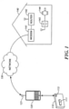
FIG. 1 , an example system comprising components and apparatuses for operating a movable barrier is shown. The system shown inFIG. 1 includes anauxiliary device 110, ahost device 120, anetwork 130, a modem 141, and amovable barrier operator 143. - The
auxiliary device 110 is a short range transmitter device configured for mounting in a vehicle. For example, theauxiliary device 110 may be a dedicated remote control including having a button 111 and a status indicator 113. In some embodiments, theauxiliary device 110 may be similar in appearance to a conventional radio frequency (RF) garage door opener. In some embodiments, the auxiliary device may be part of a built-in vehicle electronics system. Theauxiliary device 110 includes wireless communication interface configured to send short range wireless communication signals to thehost device 120. The short-range signal may be, for example, Bluetooth, infrared, Wi-Fi, and the like. In some embodiments, short-range communication signals are signals limited to 25-100mW effective radiated power (ERP) or less so that the communication range is approximately limited to being within a given vehicle. Additional details of an auxiliary device are described with reference toFIG. 2 below. - The
host device 120 is a network-enabled electronic device such as a Smartphone, a mobile communication device, a tablet computer, a wearable computer, an infotainment system, a telematics system, a personal computer, a dash computer, a dedicated computer platform, a navigation system, and an intelligent transportation system. In some embodiments, thehost device 120 is a multi-functional device such as a Smartphone configured to run one or more applications, such as mapping application, email application, music player application, internet browser application, and the like. Thehost device 120 includes movable barrier controller software that is configured to send a command to themovable barrier operator 143 in response to receiving a signal from theauxiliary device 110. For example, the software may be a downloaded movable barrier controller application installed on a Smartphone. In some embodiments, the movable barrier controller software also provides a user interface on thehost device 120 that allows the user to control and/or monitor one or more movable barriers through the display and input devices of thehost device 120. The host device also includes anetwork interface 121 for communicating with thenetwork 130. Additional details of a host device are described with reference toFIG. 2 below. - The
network 130 is a data communication network which may be, for example, the Internet. While not shown, it is understood that thenetwork 130 may include various components such as routers, transmission towers, servers, and the like for relaying the communication between the home network modem 141 and thehost device 120. Thenetwork 130 may further include a barrier operator server (not shown), which processes the data received from the host device prior to sending the data to the movable barrier operator. For example, in some embodiments, the host device sends a message to the barrier operator server with only an identification number of a movable barrier operator and/or the user, and the server routes the message to the movable barrier with the information relating to that movable barrier operator stored on the server. In some embodiments, the message may be stored on the server until the movable barrier operator queries the server for messages. In some embodiments, a dedicated barrier operator server is not needed and the message may be sent through other types of communication server. For example, thehost device 120 may send a text message to a phone number or an email to an email address monitored by the movable barrier operator using the text message and email servers respectively. - A local network is represented by a house 140 in
FIG. 1 ; however, it is understood that the components shown as being in the house 140 need not be physically located in a residence. The modem 141 is connected to thenetwork 130 to receive messages from thehost device 120 through thenetwork 130. The message may be a command to operate themovable barrier operator 143 or a query for the status of the movable barrier (not shown). The message is routed through thelocal network router 142 to the network enabledmovable barrier operator 143. - The
movable barrier operator 143 may be a garage door operator, a gate operator, a commercial door operator, an arm barrier operator and the like.FIG. 1 also shows the movable barrier operator being coupled to amotor 144 for actuating a movable barrier. WhileFIG. 1 shows that therouter 142 and themovable barrier operator 143 communicating wirelessly, it is understood that the connection may also be wired. Additionally, in some embodiments, themovable barrier operator 143 may directly communicate with the network without the modem 141 androuter 142. For example, themovable barrier operator 143 may be a network enabled device configured to directly access the cellular, mobile data, or other types of wireless network. - While
FIG. 1 illustrates thehost device 120 and theauxiliary device 110 as being outside of the house 140, it should be understood that the system is also configured to operate with thehost device 120 and theauxiliary device 110 near or inside the house 140. Thehost device 120 is located in a vehicle and theauxiliary device 110 is configured for mounting in a vehicle.movable barrier operator 143 is configured to receive signal directly from theauxiliary device 110 in case thehost device 120 is not available. For example, the auxiliary device may be equipped with both a Bluetooth transceiver (2400-2483.5 MHz) and a 200MHz to 400MHz transmitter, a frequency compatible with conventional garage door openers (GDO). In some embodiments, theauxiliary device 110 may transmit both a Bluetooth signal to thehost device 120 and a RF signal directly receivable by themovable barrier operator 143 when the user pushes the button 111. A user can selectively configure theauxiliary device 110 to transmit one or both of a Bluetooth signal and a GDO signal. Theauxiliary device 110 includes a switch for enabling and disabling GDO signal transmission. In some embodiments, the user can also configure theauxiliary device 110 with a Bluetooth transmitter to only transmit a GDO signal, thus functioning essentially as a conventional GDO. In some embodiments, the information required to transmit the GDO signal is stored on a local memory of theauxiliary device 110. In some embodiments, theauxiliary device 110 is configured to obtain and/or update the information required to transmit a GDO signal from thehost device 120. - The
movable barrier operator 143 is configured to respond to status change requests received through the network and through a 200MHz to 400 MHz RF receiver. In some embodiments, themovable barrier operator 143 may be configured by a user to respond only to status change requests from the network or from the RF receiver. For example, if a GDO remote is misplaced, a user can disable the movable barrier operator's GDO receiver with either a networked device or a switch on themovable barrier operator 143, and still operate the movable barrier with an authorized networked device. - While only one
host device 120, oneauxiliary device 110, and onemovable barrier operator 143 are shown inFIG. 1 , in some embodiments each auxiliary device may be configured to communicate with multiple host devices, each host device may be configured to communicate with multiple auxiliary devices, and each movable barrier operator may be configured to receive message from multiple host devices. - The system shown in
FIG. 1 allows theauxiliary device 110 to operate themovable barrier operator 143 at any location that thehost device 120 can directly or indirectly access over thenetwork 130. Theauxiliary device 110 also removes the need for a user to navigate through various menus and options of thehost device 120 to access the interface that allows the user to remotely control a movable barrier operator. For example, theauxiliary device 110 may be clipped to a vehicle visor and a driver can reach for and press the button 111 on theauxiliary device 110 without taking his eyes off the road. A driver can also quickly glance over to the auxiliary device to check the status of the movable barrier operator displayed on the status indicator 113 to make sure the garage door is closed. - Next referring to
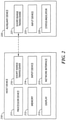
FIG. 2 , a paired set ofhost device 210 andauxiliary device 220 is shown. Thehost device 210 includes aprocessor device 211, amemory 212, adisplay 213,input device 214, anetwork interface 215, and a short-range transceiver 216. Thehost device 210 is a network-enabled electronic device such as a Smartphone, a tablet computer, a wearable computer, an infotainment system, a telematics system, a personal computer, a dash computer, a dedicated computer platform, a navigation system, and an intelligent transportation system. - The
memory 212 may include one or more of a hard disk, solid state drive, RAM, and other types of non-transitory storage memory. For example, thememory 212 may include one or more of the built-in mass storage, on-board RAM, inserted SD memory card, and SIM card memory of a Smartphone device. Thememory 212 may store a number of software programs or apps executable by theprocessor device 211, including a movable barrier operator controller program. The movable barrier controller program is configured to communicate with one or more movable barrier operators to operate the movable barrier and/or to receive status indication. The movable barrier operator controller program may include its own user interface to allow a user to operate a movable barrier operator with the host device. The movable barrier controller program may further include a user interface to allow a user to configure various settings associated with the operation of movable barrier. For example, the user interface may allow the user to associate thehost device 210 with one or moreauxiliary devices 220 and/or one or more movable barrier operators. In some embodiments, the user setting is also stored on thememory 212; in other embodiments, the user setting is stored on a movable barrier operator server in the data cloud. In some embodiments, the movable barrier program includes a background process that monitors for signals from theauxiliary device 220, a movable barrier operator, and/or a server. In some embodiments, thememory 212 also stores an operating system, such as Windows®, iOS®, Android™, BlackBerry® - OS, and the like. The
memory 212 may also store authentication information of auxiliary device(s) that had been paired with thehost device 210. The memory may further store information of associated movable barrier operator(s) needed to send messages and commands to the movable barrier operator(s). - The
display 213 may be any type of known displays, such as liquid crystal display (LCD), light emitting diode (LED) display, organic light emitting diode (OLED) display, E-Paper, and the like. Thedisplay 213 may be build-in screen incorporated with a vehicle's telematic system. Thedisplay 213 is configured to display the user interface of the various operating system and/or program executed by theprocessor device 211, - The
input device 214 may be any type of known user input devices including a touch screen, a touch pad, a keypad, a keyboard, one or more buttons, a microphone, a camera, a joystick, and the like. Theinput device 214 allows the user to interface with various programs executed by theprocessor device 211. In some embodiments, thedisplay 213 and theinput device 214 are integrated in the form of a touch screen device. - The
network interface 215 is a communication interface that allows the host device 21 to connect to a network. Thenetwork interface 215 may include one or more of a cellular network transceiver, a Wi-Fi modem, a wireless broadband modem, a mobile data network modem and the like. Thenetwork interface 215 may be configured to connect to the internet and/or a private network to communicate with a movable barrier operator and/or a server. - The short-
range transceiver 216 is a short-range radio frequency communication interface. For example, the short-range transceiver may include a low-power transmitter with less than 100 mW effective radiated power (ERP), depending on the frequency band, which limits their useful range to few hundred meters, and do not require a license from its user. For example, in some embodiments, the short-range transceiver 216 may be a Bluetooth® transceiver which operates in the range of 2400-2483.5MHz. Thehost device 210 may communicate with one or more devices through the short-range transceiver 216. - The
host device 210 may further include a location determination function such as a global positioning system (GPS) receiver (not shown) and/or other types of sensors such as motion sensor, accelerometer, microphone, camera, and the like. In some embodiments, one host device may be associated with multiple movable barrier operators. The movable barrier operator controller software on thehost device 210 may select a movable barrier operator to control based on the proximity of the host device to the movable barrier operators using the host device's location determination function, such as receipt of a GPS signal, receipt of a WiFi signal, triangulation via communication with multiple other antennas, and the like. For example, the software may determine the host device's location and compare that information with stored information regarding the locations of certain movable barrier operators as may be programmed by a user. In this manner, the host device can determine which movable barrier operator is the closest to the current location of the host device, and sends the message to the closest movable barrier operator. - The
auxiliary device 220 includes a short-range transceiver 221, aninput device 223, and astatus indicator 225. Theauxiliary device 220 may be a short-range transmitter and may be a dedicated movable barrier operator controller device. In some embodiments, the auxiliary device may be similar in dimensions and appearance to a conventional garage door remote control. In other embodiments, the auxiliary device may be integrated with other devices, such as a vehicle on-board electronics system. - The short-
range transceiver 221 of theauxiliary device 220 may be similar to the short-range transceiver 216 of thehost device 210. The short-range transceiver 221 provides a way for theauxiliary device 220 to communicate with thehost device 210. Theinput device 223 may be any type of common input means including a the user input device comprises at least one of a button, a capacitance input, a touch screen, a switch, a microphone, and a motion sensor. Theinput device 223 allows a user to cause theauxiliary device 220 to send a signal to thehost device 210 to request a status change on the movable barrier. For example, a user may press a button on theauxiliary device 220 to open or close a garage door through thehost device 210. In some embodiments, theinput device 223 may allow the user to specify whether the desired status is open or closed. In some embodiments, theauxiliary device 220 may include multiple buttons, each pre-programmed for a different movable barrier operator. The signal from theauxiliary device 220 to thehost device 210 may then include information associated with which button is pushed. - The
status indicator 225 may be any type of display that can indicate at least two statuses (e.g. open or close). For example, the status indicator may be an LED bulb(s), an LED array, an LCD display, a bistable display, and the like. The status indicator may also include one or more of a light producing device, a light emitting diode, a video display, a liquid crystal display, a touch screen display, and a sound producing device. Theauxiliary device 220 may be configured to receive movable barrier status information from thehost device 210 and display the status of the movable barrier (e.g., open or closed) through thestatus indicator 225. The movable barrier status information may be information related to the position and/or movement of a movable barrier such as open, close, moving, opening, closing, locked, unlocked, connected, disconnected, and the like. In some embodiments, the status indicator may be configured to display the status of multiple movable barriers. For example, in an embodiment of theauxiliary device 220 having multiple inputs associated with multiple movable barriers, a status indicator may be associated with each of the multiple inputs. In some embodiments, the status indicator constantly displays the status of movable barrier(s). In other embodiments, a user can use aninput device 223 to trigger the display of status on the status indicator. In some embodiments, thestatus indicator 225 is only turned on in specific statuses and is off in other statuses. For example, a LED light may only be lit when a garage door is open, and is turned off when the garage door is closed. - While the
auxiliary device 220 is shown with three components inFIG. 2 , it is understood that the auxiliary device may include additional components. For example, theauxiliary device 220 may include a housing enclosing theshort range transceiver 221, theinput device 223, and thestatus indicator 225. The auxiliary device may further include means for attaching theauxiliary device 220 to another structure. The attachment means may be a clip, a clap, a hook and loop strip, a suction cup, and the like. The auxiliary 220 device may also include an independent power source such as a battery. Theauxiliary device 220 may further include a memory for storing authentication information of the host device(s) with which it had previously authenticated. - In other embodiments, an
auxiliary device 220 may not include astatus indicator 225. Thetransceivers 221 may be a transmitters instead. That is, theauxiliary device 220 may only be configured to send status change requests but does not receive the movable barrier status information. - The
auxiliary device 220 includes a short-range transmitter, such as a GDO transmitter, in addition to the short-range transceiver 221. When a user actuates theinput device 223, the auxiliary device may transmit a GDO signal through the GDO transmitter in addition to transmitting the short-range signal through the short-range transceiver 221. The auxiliary device further includes one or more switches for enabling and disabling the GDO transmitter and/or the short-range transceiver 221. For example, a user may place the switch in one position to transmit both a GDO signal and a Bluetooth signal, and move the switch to a second position to transmit only a Bluetooth signal. In some embodiments, the transmitter/transceiver may be configured through thehost device 210. For example, movable operator controller application on thehost device 210 may allow the user to enable and disable the GDO transmitter on theauxiliary device 220. In some embodiments, the movable operator controller allows the user to configure whether to send a GDO transmitter and/or a Bluetooth signal based on the movable barrier operator being operated by the signal. In some embodiments, the short-range transceiver 221 and the GDO transmitter may respond to different user inputs. For example, different buttons may be associated with the short-range transceiver 221 and the GDO transmitter. The buttons may be configured to operate the same or different movable barrier operators. -
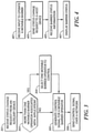
FIG. 3 shows a flow diagram of an example method for remotely operating a movable barrier as implemented on a host device. Atstep 301, the host device receives a status change request from an auxiliary device. The signal from the auxiliary device may be a simple trigger signal or it may specify whether the desired movable barrier status should be opened or closed. The signal may also indicate which of a plurality of movable barriers should receive the command to change status. In some embodiments, the status change request is a short-range radio frequency signal such as a Bluetooth® signal. Atstep 301, the host device may additionally verify the authentication status of the auxiliary device. For example, the host device may determine whether the auxiliary device sending the signal has permission to control the movable barrier operator. Step 301 may be a function of movable barrier operator application software, the operating system, and/or a background monitoring process running on the host device. - At
step 303, the host device determines whether more than one movable barrier operator are associated with the application running on the host device. In some embodiments, one host device may have stored in its memory information relating to multiple movable barrier operators that it can communicate with and control. For example, one host device may be configured to control an office parking garage gate, a community gate, and a residential garage gate. If there are multiple movable barrier operators associated with the host device, the process moves to step 304. If only one movable barrier operator is associated with the application, the process may proceed directly to step 305. In some embodiments, the movable barrier controller application is only configured to communicate with one movable barrier operator, and bothsteps - At
step 304, the application selects one movable barrier operator to control. The selection may be based on one or more factors. In some embodiments, the user may select a default movable barrier operator for the host device. The default movable barrier operator may further be configured to automatically change based on time of day, date of week, location of the host device, etc. In some embodiments, the host device uses a GPS signal or other location determination to determine which movable barrier operator is the closest to the host device to select a movable barrier operator to control. In some embodiments, the signal from an auxiliary device causes the host display to display options and/or status for the multiple movable barrier operators on its display screen for the user to select. In some embodiments, one movable barrier operator is selected based the input received on the auxiliary device. For example, the auxiliary device may have separate buttons for the community gate and the residential garage door, and a different signal is sent to the host device based on which button is pressed. In some embodiments, the movable barrier operator is selected based on the identity of the auxiliary device sending the signal. For example, one auxiliary device may be configured to only control a first gate, and a second auxiliary may be configured to control a second gate. The host device may be configured to allow a user to select and edit one or more of the above configurations with a user interface of the movable barrier controller application, and determine a movable barrier operator based on the stored user configuration. - At
step 305, the host device generates a control signal for a movable barrier operator. The control signal may be a status change request which opens the movable barrier if it is currently closed, and closes the movable barrier if it is currently open. In some embodiments, the control signal may specify whether the desired status is opened or closed such that the operator then determines whether to operate based on the received control signal and the current state of the barrier. In some embodiments, the control signal may include information necessary to establish that the host device has permission to change the status of the movable barrier operator. For example, the control signal may be encrypted with a passcode or include other encryption such as rolling code encryption. - At
step 306, the control signal is sent over a network to the movable barrier operator. The control signal may be sent via a network interface of the host device such as a Wi-Fi module, a cellular data antenna, and the like. In some embodiments, the control signal may be sent in the form of a data packet, a text message, a voice call, or an email. In some embodiments, afterstep 306, the host device may receive a confirmation signal from the movable barrier operator through the network to confirm that the requested status change has been completed. In some embodiments, the confirmation signal may be barrier status information. In some embodiment, the control signal and/or the confirmation signal is routed through a server such as a dedicated movable barrier controller server. - In some embodiments, prior to step 301 of the method shown in
FIG. 3 , the host device may first be required to authenticate with one or more auxiliary devices. For example, a user may enter a pass code or device code associated with the auxiliary device on the host device for the host device to accept status change request signals from the auxiliary device in the future. Also prior to step 301, the host device may also authenticate with a movable barrier operator. For example, the user may be required to enter a pass code or the device code associated with the movable barrier operator for the host device to send control commands to the movable barrier operators. In some embodiments, the pass code or the device code may be encrypted into the control signal each time a message is sent between the various devices to ensure that only host devices with permission to operate the movable barrier operator can cause the movable barrier to move. In some embodiments, authentication may include the user logging into a movable operator server to access a user profile that may be associated with one or more movable barrier operator. - Additionally, prior to, during, and/or after the method shown in
FIG. 3 , the host device may further periodically query for movable barrier status from the movable barrier operator. In some embodiments, the movable barrier operator updates the information stored on a server when the status of the movable barrier changes, and the host device periodically retrieves the status information form the server. -
FIG. 4 shows a flow diagram of a method for remotely operating a movable barrier as implemented on an auxiliary device. Atstep 401, the auxiliary device receives a user input to operate a moveable barrier. The user input may be a user operating an input device such as a button, a keypad, a touchpad, a switch, and the like on the auxiliary device. In some embodiments, the user input may also be a voice command, a gesture command, and the like. - At
step 403, the auxiliary device sends a status change request to a host device. Step 403 occurs in response to step 401. The status change request may be sent through a previously established communication link with a host device. The communication link is a short-range radio frequency communication channel. In some embodiments, the status change request is broadcasted to all nearby devices. The status change request may be a trigger that requests a change from the current barrier status, whether the current status is opened or closed. In other embodiments, the status change request may specify whether the desired status is opened or closed. In some embodiments, the status change request may specify which movable barrier operator to control based on the user input instep 401. For example, the status change request may be based on which button the user pushes on the auxiliary device. - At
step 405, the auxiliary device receives the barrier status information from the host device. Step 405 may occur after each time a status change request is sent to a host device instep 403. In some embodiments, the barrier status information also functions as a confirmation of the receipt of the status change request. Alternatively, prior to step 405, the host device may send a separate confirmation signal. In some embodiments,step 405 occurs periodically with or withoutsteps step 405 includes storing the received barrier status information on a memory on the auxiliary device. In some embodiments, the stored status memory may be used to determine whether the desired status is open or close when a user input is received instep 401. In another approach, no barrier status information is received at all by the auxiliary device, such information being available instead only from the host device. - At
step 407, the barrier status is displayed on a status indicator of the auxiliary device. The status indicator may be LED bulb(s), a LED array, a LCD display, a bistable display, and the like. In some embodiments, the status indicator may display the status of multiple movable barriers. For example, in an embodiment of the auxiliary device having multiple inputs associated with multiple movable barriers, a status indicator may be associated with each of the multiple inputs. In some embodiments, the status indicator constantly displays the status of movable barrier(s). In other embodiments, a user can use an input device to trigger the display of status on the status indicator. The display of barrier status may be changed based on the barrier status information received instep 405. - The above approach combines the accessibility with a conventional remote control and the versatility of a networked movable barrier controller application. A driver can simply reach for the remote control device and press a button to operate the garage door without having the take his eyes off the road. This system also allows for various user configurable settings that can be tailored to each user's individual needs and usage pattern. The system also provides an added layer of security in case the remote control is misplaced or stolen. In such a case, the remote control will not be able to open a movable barrier on its own. The user can also revoke the authentication of the host and/or auxiliary device if one or both is lost through another networked device for added security.
- Accordingly, the embodiments described above provide security to the owner of a garage door opener by removing the ability for a transmitter to function when it is distant from a vehicle in which it is normally used. By adding a secondary transmitter within the vehicle and requiring the primary transmitter to receive an identification signal from the secondary transmitter, the primary transmitter would have knowledge that it is close enough to the vehicle in order to activate the garage door opener to perform various functions.
- Those skilled in the art will recognize that a wide variety of modifications, alterations, and combinations can be made with respect to the above described embodiments without departing from the scope of the invention, as defined by the appended claims. For example, any of the signals or commands sent or received by the host device, auxiliary device, and movable barrier operator may be encrypted according to various methods.
Claims (14)
- A system for commanding a movable barrier operator (143), the system comprising:a network-enabled electronic host device (120, 210) located in a vehicle and configured to run a movable barrier controller application and to generate and send, using the movable barrier controller application, a control signal to a movable barrier operator (143); andan auxiliary device (110, 220) configured for mounting in the vehicle, the auxiliary device (110, 220) comprising:a short-range radio frequency communication interface (221) configured to communicate with the network-enabled electronic host device (110, 220) running the movable barrier controller application;a user input device (111, 223) configured to receive a user input and, in response to receiving the user input, cause the communication interface (221) to send a status change request to the network-enabled electronic host device (120, 210); anda short-range transmitter adapted to send a radio frequency 'RF' signal to the movable barrier operator (143);wherein the status change request is configured to cause the movable barrier controller application to generate the control signal that will cause the moveable barrier operator (143) to move a moveable barrier and cause the network-enabled electronic host device (120, 210) to send the control signal to the movable barrier operator (143) over a network (130);characterized in that the auxiliary device (110, 220) comprises a switch for enabling and disabling at least one of the short-range transmitter and the short-range radio frequency communication interface (221) and in that the auxiliary device (110, 220) is adapted based on the switch to selectively send, upon actuation of the user input device (111, 223), one or both of: the status change request to the network-enabled electronic host device (120, 210) and a radio frequency RF signal directly to the movable barrier operator (143).
- The system of claim 1, wherein the switch includes:a position to enable the short-range transmitter for sending the RF signal, and to enable the communication interface (221) for sending the status change request; andanother position to disable one of the short-range transmitter and the communication interface (221).
- The system of claim 1 or 2, wherein the switch is also adapted to be configured through the movable barrier controller application on the network-enabled electronic host device (110, 220).
- The system of any one of the preceding claims, wherein the auxiliary device (110, 210) further comprises:a barrier status indicator (113, 225),wherein the communication interface (221) is further configured to receive barrier status information from the network-enabled electronic host device (120, 210) and wherein the barrier status indicator (113, 225) displays the barrier status information.
- The system of any one of the preceding claims, further comprising: a storage memory (212) for storing authentication information, wherein the auxiliary device (110, 210) is configured to authenticate with the network-enabled electronic host device (120, 210) prior to sending the status change request, and optionally wherein the network-enabled electronic host device (120, 210) is adapted to determine whether the auxiliary device (110, 220), from which the status change request originated, has permission to control the movable barrier operator (143) based on the authentication information.
- The system of any one of the preceding claims, wherein the network-enabled electronic host device (120, 210) is associated with a plurality of movable barrier operators, and optionally wherein the network-enabled electronic host device (120, 210) is further configured to select one of the movable barrier operators based on one or more factors including: a default, a time of day, a day of week, and a location of the network-enabled electronic host device (120, 210), and further optionally wherein the network-enabled electronic host device (120, 210) is further configured to determine a location of the network-enabled electronic host device (120, 210), to compare the location of the network-enabled electronic host device (120, 210) to a location of a movable barrier operator (143), and to generate the control signal based in part on the location of the network-enabled electronic host device (120, 210) and the location of a closest movable barrier operator (143) of the plurality of movable barrier operators.
- The system of any one of claims 1-3, wherein the auxiliary device (110, 220) is configured to pair with the network-enabled electronic host device (120, 210), and optionally wherein the communication interface (221) and the short range transmitter comprise Bluetooth transceivers for pairing.
- The system of any one of the preceding claims, wherein the network-enabled electronic host device (120, 220) is configured in the vehicle as an infotainment system, a telematics system, a dash computer, a navigation system, or an intelligent transportation system.
- A method for commanding a movable barrier operator (143) with a system according to any one of claims 1-8, a network-enabled electronic host device (120, 210) being located in a vehicle for commanding a movable barrier operator (143), the method comprising:receiving an input to operate a movable barrier at an auxiliary device (110, 220) configured for mounting in the vehicle;sending, via a short-range radio frequency communication interface (221) of the auxiliary device (110, 220), a status change request to the network-enabled electronic host device (120, 210), the network-enabled electronic host device (120, 210) running a movable barrier controller application;wherein the status change request is configured to cause the movable barrier controller application to generate a control signal and cause the network-enabled electronic host device (120, 210) to send the control signal to the movable barrier operator (143) over a network (130); andcharacterized in that the auxiliary device (110, 220) further comprises: a short range transmitter adapted to send a radio frequency 'RF' signal to the movable barrier operator (143); and a switch for enabling and disabling at least one of the short range transmitter and the short range radio frequency communication interface (221); wherein the auxiliary device (110, 220) is adapted to selectively send, upon actuation of the user input device (111, 223), one or both of: the status change request to the network-enabled electronic host device (120, 210) and a radio frequency RF signal directly to the movable barrier operator (143).
- The method of claim 9, wherein the network-enabled electronic host device (120, 210) comprises a short range transmitter, and optionally wherein the short-range radio frequency communication interface and the short range transmitter comprise Bluetooth transceivers for pairing.
- The method of claim 9 or 10, further comprising:receiving barrier status information from the network-enabled electronic host device (120, 210) through the communication interface (221); anddisplaying barrier status information on a barrier status indicator (113, 225).
- The method of claim 9, further comprising:
storing authentication information on a storage memory (212) and authenticating with the network-enabled electronic host device (120, 210) prior to sending the status change request, and optionally wherein the network-enabled electronic host device (120, 210) is adapted to determine whether the auxiliary device (110, 220), from which the status change request originated, has permission to control the movable barrier operator (143) based on the authentication information. - The method of any one of claims 9 to 12, wherein the network-enabled electronic host device (120, 220) is configured in the vehicle as an infotainment system, a telematics system, a dash computer, a navigation system, or an intelligent transportation system.
- An auxiliary device (110, 220) adapted for use with a network-enabled electronic host device (120, 210) located in a vehicle, the network-enabled electronic host device configured to run a movable barrier controller application and to generate and send, using the movable barrier controller application, a control signal to a movable barrier operator for commanding the movable barrier operator (143), wherein the auxiliary device (110, 220) is configured for mounting in a vehicle, the auxiliary device (110, 220) comprising:a short-range radio frequency communication interface (221) configured to communicate with the network-enabled electronic host device (110, 220) running the movable barrier controller application;a user input device (111, 223) configured to receive a user input and, in response to receiving the user input, cause the communication interface (221) to send a status change request to the network-enabled electronic host device (120, 210);a short-range transmitter adapted to send a radio frequency 'RF' signal to the movable barrier operator (143); andwherein the status change request is configured to cause the movable barrier controller application to generate the control signal that will cause the moveable barrier operator (143) to move a moveable barrier and cause the network-enabled electronic host device (120, 210) to send the control signal to the movable barrier operator (143) over a network (130);characterized in that the auxiliary device (110, 220) comprises a switch for enabling and disabling at least one of the short-range transmitter and the short-range radio frequency communication interface (221) and in that the auxiliary device (110, 220) is adapted based on the switch to selectively send, upon actuation of the user input device (111, 223), one or both of: the status change request to the network-enabled electronic host device (120, 210) and a radio frequency RF signal directly to the movable barrier operator (143).
Applications Claiming Priority (2)
| Application Number | Priority Date | Filing Date | Title |
|---|---|---|---|
| US14/087,741 US10126737B2 (en) | 2013-11-22 | 2013-11-22 | Remotely operating a movable barrier operator with auxiliary device |
| PCT/US2014/066132 WO2015077222A1 (en) | 2013-11-22 | 2014-11-18 | Remotely operating a movable barrier operator with auxiliary device |
Publications (3)
| Publication Number | Publication Date |
|---|---|
| EP3072016A1 EP3072016A1 (en) | 2016-09-28 |
| EP3072016A4 EP3072016A4 (en) | 2017-07-19 |
| EP3072016B1 true EP3072016B1 (en) | 2022-03-16 |
Family
ID=53180069
Family Applications (1)
| Application Number | Title | Priority Date | Filing Date |
|---|---|---|---|
| EP14864870.2A Active EP3072016B1 (en) | 2013-11-22 | 2014-11-18 | Remotely operating a movable barrier operator with auxiliary device |
Country Status (5)
| Country | Link |
|---|---|
| US (2) | US10126737B2 (en) |
| EP (1) | EP3072016B1 (en) |
| AU (1) | AU2014353222B2 (en) |
| CA (1) | CA2930825C (en) |
| WO (1) | WO2015077222A1 (en) |
Families Citing this family (21)
| Publication number | Priority date | Publication date | Assignee | Title |
|---|---|---|---|---|
| US8866583B2 (en) | 2012-06-12 | 2014-10-21 | Jeffrey Ordaz | Garage door system and method |
| US10096187B2 (en) * | 2015-04-09 | 2018-10-09 | Overhead Door Corporation | Automatic transmission of a barrier status and change of status over a network |
| WO2017180290A1 (en) | 2016-04-11 | 2017-10-19 | Tti (Macao Commercial Offshore) Limited | Modular garage door opener |
| CA2961090A1 (en) | 2016-04-11 | 2017-10-11 | Tti (Macao Commercial Offshore) Limited | Modular garage door opener |
| DE202016002975U1 (en) * | 2016-05-06 | 2017-08-09 | Marantec Antriebs- Und Steuerungstechnik Gmbh & Co. Kg | Control unit for a door drive |
| WO2018053416A1 (en) * | 2016-09-19 | 2018-03-22 | The Chamberlain Group, Inc. | Location aware barrier operation |
| EP3312819A1 (en) * | 2016-10-20 | 2018-04-25 | TTI (Macao Commercial Offshore) Limited | Systems and methods for diagnostics to support operation of a garage door opener using asynchronous reporting of logged data |
| CA2987080A1 (en) * | 2016-12-02 | 2018-06-02 | Parke Pleasants | Adapter |
| CA2987088A1 (en) * | 2016-12-02 | 2018-06-02 | Mark Huggins | Garage door opener system having an intelligent automated assistant and method of controlling the same |
| US10443295B2 (en) | 2016-12-02 | 2019-10-15 | Tti (Macao Commercial Offshore) Limited | Garage door opener system having an intelligent automated assistant and method of controlling the same |
| IT201700011800A1 (en) * | 2017-02-03 | 2018-08-03 | Carlo Vignati | OPEN GATE GPS |
| DE102017002543A1 (en) * | 2017-03-15 | 2018-09-20 | Marantec Antriebs- Und Steuerungstechnik Gmbh & Co. Kg | Gate control |
| US10270493B2 (en) | 2017-07-14 | 2019-04-23 | The Chamberlain Group, Inc. | Portable rechargeable transmitter |
| US10557299B2 (en) | 2017-08-08 | 2020-02-11 | Honda Motor Co., Ltd. | System and method for automatically controlling movement of a barrier |
| US10246930B2 (en) | 2017-08-08 | 2019-04-02 | Honda Motor Co., Ltd. | System and method for remotely controlling and determining a status of a barrier |
| US10490007B2 (en) | 2017-08-08 | 2019-11-26 | Honda Motor Co., Ltd. | System and method for automatically controlling movement of a barrier |
| EP3899178A1 (en) | 2018-12-19 | 2021-10-27 | ASSA ABLOY Entrance Systems AB | Automatic door operator and method of operating automatic door operator |
| US11313168B2 (en) | 2018-12-31 | 2022-04-26 | William Kyle Virgin | Universal add-on devices for feature enhancement of openers for movable barriers |
| US11402812B1 (en) | 2019-03-22 | 2022-08-02 | The Chamberlain Group Llc | Apparatus and method for controlling a device |
| WO2020242822A1 (en) | 2019-05-30 | 2020-12-03 | D. H. Pace Company, Inc. | Systems and methods for door and dock equipment servicing |
| JP7289741B2 (en) | 2019-07-01 | 2023-06-12 | 文化シヤッター株式会社 | Opening/closing control system, opening/closing control method, application for remote control device, and mobile communication terminal device |
Citations (1)
| Publication number | Priority date | Publication date | Assignee | Title |
|---|---|---|---|---|
| WO2015073810A1 (en) * | 2013-11-15 | 2015-05-21 | Gentex Corporation | Internet-connected garage door control system |
Family Cites Families (29)
| Publication number | Priority date | Publication date | Assignee | Title |
|---|---|---|---|---|
| EP1194903B1 (en) | 1999-05-26 | 2013-11-13 | Johnson Controls Technology Company | Wireless communications system and method |
| US7346374B2 (en) | 1999-05-26 | 2008-03-18 | Johnson Controls Technology Company | Wireless communications system and method |
| EP1216899A1 (en) | 2000-12-22 | 2002-06-26 | Ford Global Technologies, Inc. | Communication system for use with a vehicle |
| US20020183008A1 (en) | 2001-05-29 | 2002-12-05 | Menard Raymond J. | Power door control and sensor module for a wireless system |
| US7167076B2 (en) | 2001-12-19 | 2007-01-23 | Lear Corporation | Universal garage door operating system and method |
| US6998977B2 (en) | 2003-04-28 | 2006-02-14 | The Chamberlain Group, Inc. | Method and apparatus for monitoring a movable barrier over a network |
| US7197278B2 (en) | 2004-01-30 | 2007-03-27 | Lear Corporation | Method and system for communicating information between a vehicular hands-free telephone system and an external device using a garage door opener as a communications gateway |
| US7124943B2 (en) | 2004-09-24 | 2006-10-24 | Assa Abloy Identification Technology Group Ab | RFID system having a field reprogrammable RFID reader |
| US20060103503A1 (en) | 2004-11-12 | 2006-05-18 | Yan Rodriguez | Networked movable barrier operator system |
| US7956718B2 (en) * | 2004-12-16 | 2011-06-07 | Overhead Door Corporation | Remote control and monitoring of barrier operators with radio frequency transceivers |
| US7532709B2 (en) | 2005-02-04 | 2009-05-12 | Styers Justin R | Remote garage door monitoring system |
| US20070046428A1 (en) | 2005-08-24 | 2007-03-01 | Wayne-Dalton Corporation | System and methods for automatically moving access barriers initiated by mobile transmitter devices |
| US7701331B2 (en) | 2006-06-12 | 2010-04-20 | Tran Bao Q | Mesh network door lock |
| US20080061926A1 (en) | 2006-07-31 | 2008-03-13 | The Chamberlain Group, Inc. | Method and apparatus for utilizing a transmitter having a range limitation to control a movable barrier operator |
| US20080169899A1 (en) * | 2007-01-12 | 2008-07-17 | Lear Corporation | Voice programmable and voice activated vehicle-based appliance remote control |
| US8761712B1 (en) * | 2007-01-23 | 2014-06-24 | Control4 Corporation | Location based remote controller for controlling different electronic devices located in different locations |
| US8330572B2 (en) * | 2007-03-16 | 2012-12-11 | Homerun Holdings Corporation | Multiple barrier control system |
| US8841988B2 (en) * | 2007-05-22 | 2014-09-23 | Lear Corporation | System having key fob operable to remotely control a garage door via remote keyless entry receiver and garage door opener transmitter interconnected by vehicle bus |
| US8791790B2 (en) | 2009-02-10 | 2014-07-29 | Yikes Llc | System and method for accessing a structure using a mobile device |
| US8581696B2 (en) | 2010-01-14 | 2013-11-12 | Lear Corporation | Universal garage door opener and appliance control system |
| WO2011159921A1 (en) | 2010-06-16 | 2011-12-22 | Delphian Systems, LLC | Wireless device enabled locking system |
| TW201234886A (en) * | 2011-01-07 | 2012-08-16 | Delphian Systems Llc | System and method for access control via mobile device |
| US8994496B2 (en) * | 2011-04-01 | 2015-03-31 | The Chamberlain Group, Inc. | Encrypted communications for a moveable barrier environment |
| EP2721871B1 (en) * | 2011-06-17 | 2020-08-12 | Yikes, LLC | System and method for accessing a structure using directional antennas and a wireless token |
| CA2890612A1 (en) | 2011-11-07 | 2013-05-16 | Kortek Industries Pty Ltd | Adaptable wireless power, light and automation system |
| US9479498B2 (en) * | 2012-09-28 | 2016-10-25 | Intel Corporation | Providing limited access to a service device via an intermediary |
| US9122302B2 (en) * | 2012-12-18 | 2015-09-01 | Yue Huang | Automatic garage door automatic monitoring and controlling system based on the internet of things concept and near field communication (NFC) technology |
| US9169684B2 (en) * | 2013-04-26 | 2015-10-27 | GM Global Technology Operations LLC | Methods, program products, and systems relating to vehicular garage door control systems |
| US10062223B2 (en) * | 2013-08-30 | 2018-08-28 | Bayerische Motoren Werke Akttiengesellschaft | Intermediary access device for communication with a vehicle |
-
2013
- 2013-11-22 US US14/087,741 patent/US10126737B2/en active Active
-
2014
- 2014-11-18 EP EP14864870.2A patent/EP3072016B1/en active Active
- 2014-11-18 WO PCT/US2014/066132 patent/WO2015077222A1/en active Application Filing
- 2014-11-18 CA CA2930825A patent/CA2930825C/en active Active
- 2014-11-18 AU AU2014353222A patent/AU2014353222B2/en active Active
-
2018
- 2018-10-30 US US16/174,695 patent/US10739762B2/en active Active
Patent Citations (1)
| Publication number | Priority date | Publication date | Assignee | Title |
|---|---|---|---|---|
| WO2015073810A1 (en) * | 2013-11-15 | 2015-05-21 | Gentex Corporation | Internet-connected garage door control system |
Also Published As
| Publication number | Publication date |
|---|---|
| AU2014353222B2 (en) | 2019-03-28 |
| EP3072016A4 (en) | 2017-07-19 |
| EP3072016A1 (en) | 2016-09-28 |
| US10126737B2 (en) | 2018-11-13 |
| CA2930825C (en) | 2023-09-05 |
| WO2015077222A1 (en) | 2015-05-28 |
| US10739762B2 (en) | 2020-08-11 |
| US20190064783A1 (en) | 2019-02-28 |
| CA2930825A1 (en) | 2015-05-28 |
| US20150148983A1 (en) | 2015-05-28 |
| AU2014353222A1 (en) | 2016-06-02 |
Similar Documents
| Publication | Publication Date | Title |
|---|---|---|
| US10739762B2 (en) | Remotely operating a movable barrier operator with auxiliary device | |
| US10730481B2 (en) | Remote control of vehicle functionalities by means of a mobile terminal | |
| US10339734B2 (en) | Internet-connected garage door control system | |
| US10529226B1 (en) | Vehicle integration with security and/or automation systems | |
| CN107054294B (en) | System and method for on-demand disabling of passive entry | |
| CN105376293B (en) | Method and system for remote vehicle access enabled key fob base station | |
| US9875649B2 (en) | Remote control systems for vehicles | |
| US11851939B2 (en) | Movable barrier operator having updatable security protocol | |
| US20170120864A1 (en) | Methods and Systems for Enabling a Vehicle Drive-Away | |
| CN109695383B (en) | Key unit, control system, control method, and non-transitory computer-readable storage medium having program stored therein | |
| US11220856B2 (en) | Movable barrier operator enhancement device and method | |
| US20220180679A1 (en) | Vehicle control system | |
| KR20170013571A (en) | Terminal connected with vehicle, vehicle, system having the same and method for conncetion to vehicle | |
| KR101602341B1 (en) | Method and system for prevent loss of smart phone in vehicle using AVN device | |
| US10290163B2 (en) | Connected vehicle communication port integrated universal garage door opener | |
| US20170064486A1 (en) | Application Software for Movable Barrier Operation | |
| KR102504469B1 (en) | Vehicle, hub apparatus and communication system comprising the same | |
| WO2023168512A1 (en) | Multiuser authenticating system and method for keyless entry and starting a vehicle |
Legal Events
| Date | Code | Title | Description |
|---|---|---|---|
| PUAI | Public reference made under article 153(3) epc to a published international application that has entered the european phase |
Free format text: ORIGINAL CODE: 0009012 |
|
| 17P | Request for examination filed |
Effective date: 20160607 |
|
| AK | Designated contracting states |
Kind code of ref document: A1 Designated state(s): AL AT BE BG CH CY CZ DE DK EE ES FI FR GB GR HR HU IE IS IT LI LT LU LV MC MK MT NL NO PL PT RO RS SE SI SK SM TR |
|
| AX | Request for extension of the european patent |
Extension state: BA ME |
|
| DAX | Request for extension of the european patent (deleted) | ||
| A4 | Supplementary search report drawn up and despatched |
Effective date: 20170616 |
|
| RIC1 | Information provided on ipc code assigned before grant |
Ipc: G05B 11/01 20060101AFI20170609BHEP |
|
| STAA | Information on the status of an ep patent application or granted ep patent |
Free format text: STATUS: EXAMINATION IS IN PROGRESS |
|
| 17Q | First examination report despatched |
Effective date: 20180620 |
|
| GRAP | Despatch of communication of intention to grant a patent |
Free format text: ORIGINAL CODE: EPIDOSNIGR1 |
|
| STAA | Information on the status of an ep patent application or granted ep patent |
Free format text: STATUS: GRANT OF PATENT IS INTENDED |
|
| INTG | Intention to grant announced |
Effective date: 20201027 |
|
| GRAJ | Information related to disapproval of communication of intention to grant by the applicant or resumption of examination proceedings by the epo deleted |
Free format text: ORIGINAL CODE: EPIDOSDIGR1 |
|
| STAA | Information on the status of an ep patent application or granted ep patent |
Free format text: STATUS: EXAMINATION IS IN PROGRESS |
|
| RAP1 | Party data changed (applicant data changed or rights of an application transferred) |
Owner name: THE CHAMBERLAIN GROUP, INC. |
|
| STAA | Information on the status of an ep patent application or granted ep patent |
Free format text: STATUS: EXAMINATION IS IN PROGRESS |
|
| INTC | Intention to grant announced (deleted) | ||
| GRAP | Despatch of communication of intention to grant a patent |
Free format text: ORIGINAL CODE: EPIDOSNIGR1 |
|
| STAA | Information on the status of an ep patent application or granted ep patent |
Free format text: STATUS: GRANT OF PATENT IS INTENDED |
|
| INTG | Intention to grant announced |
Effective date: 20211021 |
|
| GRAS | Grant fee paid |
Free format text: ORIGINAL CODE: EPIDOSNIGR3 |
|
| RAP3 | Party data changed (applicant data changed or rights of an application transferred) |
Owner name: THE CHAMBERLAIN GROUP LLC |
|
| GRAA | (expected) grant |
Free format text: ORIGINAL CODE: 0009210 |
|
| STAA | Information on the status of an ep patent application or granted ep patent |
Free format text: STATUS: THE PATENT HAS BEEN GRANTED |
|
| AK | Designated contracting states |
Kind code of ref document: B1 Designated state(s): AL AT BE BG CH CY CZ DE DK EE ES FI FR GB GR HR HU IE IS IT LI LT LU LV MC MK MT NL NO PL PT RO RS SE SI SK SM TR |
|
| REG | Reference to a national code |
Ref country code: GB Ref legal event code: FG4D |
|
| REG | Reference to a national code |
Ref country code: CH Ref legal event code: EP Ref country code: DE Ref legal event code: R096 Ref document number: 602014082882 Country of ref document: DE |
|
| REG | Reference to a national code |
Ref country code: IE Ref legal event code: FG4D |
|
| REG | Reference to a national code |
Ref country code: AT Ref legal event code: REF Ref document number: 1476333 Country of ref document: AT Kind code of ref document: T Effective date: 20220415 |
|
| REG | Reference to a national code |
Ref country code: SE Ref legal event code: TRGR |
|
| REG | Reference to a national code |
Ref country code: LT Ref legal event code: MG9D |
|
| REG | Reference to a national code |
Ref country code: NL Ref legal event code: MP Effective date: 20220316 |
|
| PG25 | Lapsed in a contracting state [announced via postgrant information from national office to epo] |
Ref country code: RS Free format text: LAPSE BECAUSE OF FAILURE TO SUBMIT A TRANSLATION OF THE DESCRIPTION OR TO PAY THE FEE WITHIN THE PRESCRIBED TIME-LIMIT Effective date: 20220316 Ref country code: NO Free format text: LAPSE BECAUSE OF FAILURE TO SUBMIT A TRANSLATION OF THE DESCRIPTION OR TO PAY THE FEE WITHIN THE PRESCRIBED TIME-LIMIT Effective date: 20220616 Ref country code: LT Free format text: LAPSE BECAUSE OF FAILURE TO SUBMIT A TRANSLATION OF THE DESCRIPTION OR TO PAY THE FEE WITHIN THE PRESCRIBED TIME-LIMIT Effective date: 20220316 Ref country code: HR Free format text: LAPSE BECAUSE OF FAILURE TO SUBMIT A TRANSLATION OF THE DESCRIPTION OR TO PAY THE FEE WITHIN THE PRESCRIBED TIME-LIMIT Effective date: 20220316 Ref country code: BG Free format text: LAPSE BECAUSE OF FAILURE TO SUBMIT A TRANSLATION OF THE DESCRIPTION OR TO PAY THE FEE WITHIN THE PRESCRIBED TIME-LIMIT Effective date: 20220616 |
|
| REG | Reference to a national code |
Ref country code: AT Ref legal event code: MK05 Ref document number: 1476333 Country of ref document: AT Kind code of ref document: T Effective date: 20220316 |
|
| PG25 | Lapsed in a contracting state [announced via postgrant information from national office to epo] |
Ref country code: LV Free format text: LAPSE BECAUSE OF FAILURE TO SUBMIT A TRANSLATION OF THE DESCRIPTION OR TO PAY THE FEE WITHIN THE PRESCRIBED TIME-LIMIT Effective date: 20220316 Ref country code: GR Free format text: LAPSE BECAUSE OF FAILURE TO SUBMIT A TRANSLATION OF THE DESCRIPTION OR TO PAY THE FEE WITHIN THE PRESCRIBED TIME-LIMIT Effective date: 20220617 Ref country code: FI Free format text: LAPSE BECAUSE OF FAILURE TO SUBMIT A TRANSLATION OF THE DESCRIPTION OR TO PAY THE FEE WITHIN THE PRESCRIBED TIME-LIMIT Effective date: 20220316 |
|
| PG25 | Lapsed in a contracting state [announced via postgrant information from national office to epo] |
Ref country code: NL Free format text: LAPSE BECAUSE OF FAILURE TO SUBMIT A TRANSLATION OF THE DESCRIPTION OR TO PAY THE FEE WITHIN THE PRESCRIBED TIME-LIMIT Effective date: 20220316 |
|
| PG25 | Lapsed in a contracting state [announced via postgrant information from national office to epo] |
Ref country code: SM Free format text: LAPSE BECAUSE OF FAILURE TO SUBMIT A TRANSLATION OF THE DESCRIPTION OR TO PAY THE FEE WITHIN THE PRESCRIBED TIME-LIMIT Effective date: 20220316 Ref country code: SK Free format text: LAPSE BECAUSE OF FAILURE TO SUBMIT A TRANSLATION OF THE DESCRIPTION OR TO PAY THE FEE WITHIN THE PRESCRIBED TIME-LIMIT Effective date: 20220316 Ref country code: RO Free format text: LAPSE BECAUSE OF FAILURE TO SUBMIT A TRANSLATION OF THE DESCRIPTION OR TO PAY THE FEE WITHIN THE PRESCRIBED TIME-LIMIT Effective date: 20220316 Ref country code: PT Free format text: LAPSE BECAUSE OF FAILURE TO SUBMIT A TRANSLATION OF THE DESCRIPTION OR TO PAY THE FEE WITHIN THE PRESCRIBED TIME-LIMIT Effective date: 20220718 Ref country code: ES Free format text: LAPSE BECAUSE OF FAILURE TO SUBMIT A TRANSLATION OF THE DESCRIPTION OR TO PAY THE FEE WITHIN THE PRESCRIBED TIME-LIMIT Effective date: 20220316 Ref country code: EE Free format text: LAPSE BECAUSE OF FAILURE TO SUBMIT A TRANSLATION OF THE DESCRIPTION OR TO PAY THE FEE WITHIN THE PRESCRIBED TIME-LIMIT Effective date: 20220316 Ref country code: CZ Free format text: LAPSE BECAUSE OF FAILURE TO SUBMIT A TRANSLATION OF THE DESCRIPTION OR TO PAY THE FEE WITHIN THE PRESCRIBED TIME-LIMIT Effective date: 20220316 Ref country code: AT Free format text: LAPSE BECAUSE OF FAILURE TO SUBMIT A TRANSLATION OF THE DESCRIPTION OR TO PAY THE FEE WITHIN THE PRESCRIBED TIME-LIMIT Effective date: 20220316 |
|
| PG25 | Lapsed in a contracting state [announced via postgrant information from national office to epo] |
Ref country code: PL Free format text: LAPSE BECAUSE OF FAILURE TO SUBMIT A TRANSLATION OF THE DESCRIPTION OR TO PAY THE FEE WITHIN THE PRESCRIBED TIME-LIMIT Effective date: 20220316 Ref country code: IS Free format text: LAPSE BECAUSE OF FAILURE TO SUBMIT A TRANSLATION OF THE DESCRIPTION OR TO PAY THE FEE WITHIN THE PRESCRIBED TIME-LIMIT Effective date: 20220716 Ref country code: AL Free format text: LAPSE BECAUSE OF FAILURE TO SUBMIT A TRANSLATION OF THE DESCRIPTION OR TO PAY THE FEE WITHIN THE PRESCRIBED TIME-LIMIT Effective date: 20220316 |
|
| REG | Reference to a national code |
Ref country code: DE Ref legal event code: R097 Ref document number: 602014082882 Country of ref document: DE |
|
| PLBE | No opposition filed within time limit |
Free format text: ORIGINAL CODE: 0009261 |
|
| STAA | Information on the status of an ep patent application or granted ep patent |
Free format text: STATUS: NO OPPOSITION FILED WITHIN TIME LIMIT |
|
| PG25 | Lapsed in a contracting state [announced via postgrant information from national office to epo] |
Ref country code: DK Free format text: LAPSE BECAUSE OF FAILURE TO SUBMIT A TRANSLATION OF THE DESCRIPTION OR TO PAY THE FEE WITHIN THE PRESCRIBED TIME-LIMIT Effective date: 20220316 |
|
| 26N | No opposition filed |
Effective date: 20221219 |
|
| PG25 | Lapsed in a contracting state [announced via postgrant information from national office to epo] |
Ref country code: SI Free format text: LAPSE BECAUSE OF FAILURE TO SUBMIT A TRANSLATION OF THE DESCRIPTION OR TO PAY THE FEE WITHIN THE PRESCRIBED TIME-LIMIT Effective date: 20220316 |
|
| PG25 | Lapsed in a contracting state [announced via postgrant information from national office to epo] |
Ref country code: MC Free format text: LAPSE BECAUSE OF FAILURE TO SUBMIT A TRANSLATION OF THE DESCRIPTION OR TO PAY THE FEE WITHIN THE PRESCRIBED TIME-LIMIT Effective date: 20220316 |
|
| REG | Reference to a national code |
Ref country code: CH Ref legal event code: PL |
|
| REG | Reference to a national code |
Ref country code: BE Ref legal event code: MM Effective date: 20221130 |
|
| PG25 | Lapsed in a contracting state [announced via postgrant information from national office to epo] |
Ref country code: LI Free format text: LAPSE BECAUSE OF NON-PAYMENT OF DUE FEES Effective date: 20221130 Ref country code: CH Free format text: LAPSE BECAUSE OF NON-PAYMENT OF DUE FEES Effective date: 20221130 |
|
| PG25 | Lapsed in a contracting state [announced via postgrant information from national office to epo] |
Ref country code: LU Free format text: LAPSE BECAUSE OF NON-PAYMENT OF DUE FEES Effective date: 20221118 |
|
| PG25 | Lapsed in a contracting state [announced via postgrant information from national office to epo] |
Ref country code: IE Free format text: LAPSE BECAUSE OF NON-PAYMENT OF DUE FEES Effective date: 20221118 |
|
| PGFP | Annual fee paid to national office [announced via postgrant information from national office to epo] |
Ref country code: GB Payment date: 20230928 Year of fee payment: 10 |
|
| PG25 | Lapsed in a contracting state [announced via postgrant information from national office to epo] |
Ref country code: BE Free format text: LAPSE BECAUSE OF NON-PAYMENT OF DUE FEES Effective date: 20221130 |
|
| PGFP | Annual fee paid to national office [announced via postgrant information from national office to epo] |
Ref country code: SE Payment date: 20230912 Year of fee payment: 10 Ref country code: FR Payment date: 20230911 Year of fee payment: 10 |
|
| PGFP | Annual fee paid to national office [announced via postgrant information from national office to epo] |
Ref country code: IT Payment date: 20231010 Year of fee payment: 10 Ref country code: DE Payment date: 20230926 Year of fee payment: 10 |
|
| PG25 | Lapsed in a contracting state [announced via postgrant information from national office to epo] |
Ref country code: HU Free format text: LAPSE BECAUSE OF FAILURE TO SUBMIT A TRANSLATION OF THE DESCRIPTION OR TO PAY THE FEE WITHIN THE PRESCRIBED TIME-LIMIT; INVALID AB INITIO Effective date: 20141118 |